introduction to traffic signals adam kirk. identify 1 part of the traffic signal
TRANSCRIPT

Introduction to Traffic Signals
Adam Kirk
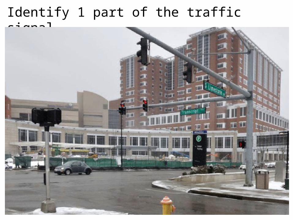
Identify 1 part of the traffic signal

• Why do we have traffic signals?
• How many traffic signals are in Kentucky

Terminology
• Indication-The illumination of one or more signal lenses indicating an allowed or prohibited movement.
• Interval-A period of time during which all signal indications remain the same for all approaches.
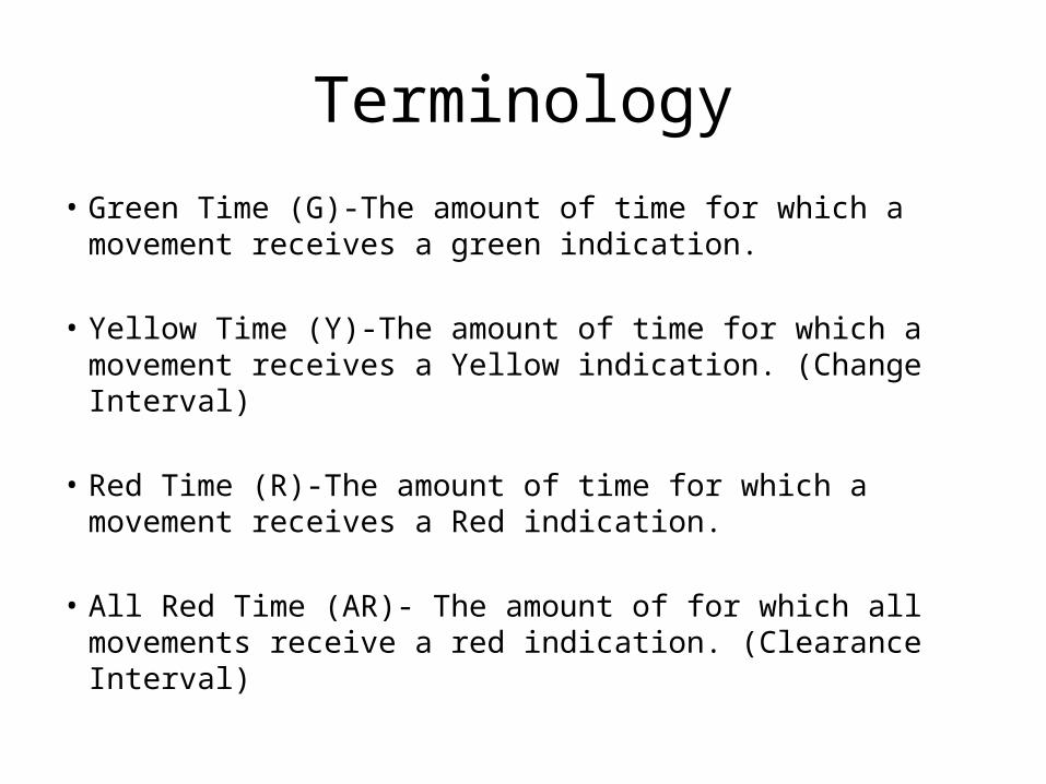
Terminology
• Green Time (G)-The amount of time for which a movement receives a green indication.
• Yellow Time (Y)-The amount of time for which a movement receives a Yellow indication. (Change Interval)
• Red Time (R)-The amount of time for which a movement receives a Red indication.
• All Red Time (AR)- The amount of for which all movements receive a red indication. (Clearance Interval)

Terminology
• Phase- The green time, yellow change, and red clearance intervals in a cycle that are assigned to an independent traffic movement or combination of traffic movements.

Terminology
• Phase Diagram

Terminology
• Cycle -One completed sequence of all phases.
• Cycle Length (C)-The total time for the signal to complete one cycle.

Types of Movements
• Protected Movement-A movement that has the right of way and does not yield to conflicting movements
• Permitted Movement-A movement that must yield to opposing traffic flow.

Types of Movements
• Protected or Permitted Left Turn?• Protected or Permitted Right Turn?• Protected or Permitted Through Movement?

Types of Movements
• Protected or Permitted Left Turn?

Types of Movements
• Protected or Permitted Left Turn?

Types of Movements
• Protected or Permitted Left Turn?

Types of Movements
• Protected or Permitted Left Turn?
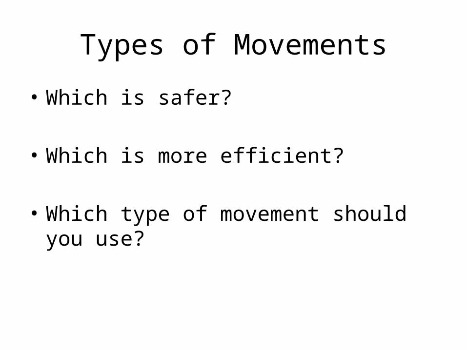
Types of Movements
• Which is safer?
• Which is more efficient?
• Which type of movement should you use?
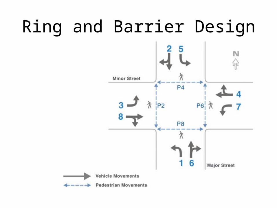
Ring and Barrier Design

Ring and Barrier Design

Types of Traffic Signals
• Pre-timed-A signal whose timing (and phasing) is fixed.
• Actuated-A signal whose timing (and phasing) is influenced by traffic volumes at the intersections.
• Semi-Actuated-a signal whose timing (and phasing) is influenced by traffic on some, but not all, approaches.
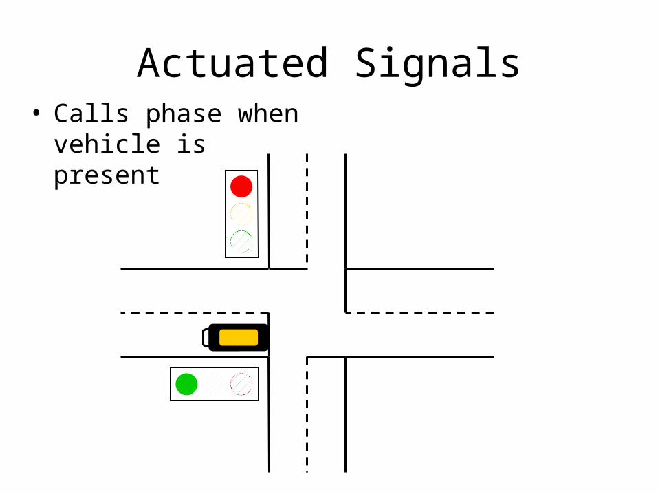
Actuated Signals• Calls phase when
vehicle is present

Actuated Signal Timing
• Extends green time to match demand

Actuated Signal Timing
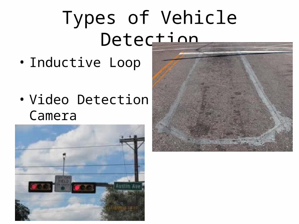
Types of Vehicle Detection
• Inductive Loop
• Video Detection Camera

Inductive Loops – How They Work

Inductive Loops – How They Work
When a vehicle enters or crosses the loop, the body and frame provide a conductive path for the magnetic field. This produces a loading effect, which in turn causes the loop inductance to decrease.

Inductive Loops – How They Work
The decreased inductance causes the resonant frequency to increase from its nominal value. If the frequency change exceeds the threshold set by the sensitivity setting, the detector module will output a detect signal to the controller.

Vehicle Detection
• Video Detection Camera