introduction to wind energy...
TRANSCRIPT

International School on Energy, 17-23 July 2014, Varenna, Lake Como
Introduction to Wind Energy Systems
Hermann-Josef Wagner
Institute for Energy Systems and Energy Economy
Ruhr-University Bochum, Germany
Structure of my presentation
• Present status of wind energy use
• Physical and meteorological basics
• Techniques of wind converters
• Off shore windparks
• Wind use in Europe

Electricity from wind energy
Source: DEWI Magazin, No. 44; Feb. 2014,p.36
Status of installed wind power
Rated Capacity
End of 2013 [GW]
Share
worldwide [%]
China 91 29
USA 61 19
Germany 35 11
Spain 23 7
India 20 6
UK 11 3
Italy 9 3
France 8 3
Canada 8 2
Denmark 5 2
Remaining
countries 48 15
Total 319 100

Shares of the suppliers in the world market
New erected capacity 2012:
44.700 MW
Source: http://de.statista.com/statistik/daten/studie/169595/umfrage/marktanteile-der-groessten-windturbinen-produzenten-weltweit/

Structure of my presentation
• Present status of wind energy use
• Physical and meteorological basics
• Techniques of wind converters
• Off shore windparks
• Wind use in Europe

Energy and power density of wind
Derivative of the equation with steady velocity of wind v
Kinetic energy E of a mass element Δ m
Efficiency
V = volume
ρL = density of air
= 1,2 kg/m³

Velocity triangle at the rotor blade
Bird‘s eye view of horizontally positioned rotor blades
Bird‘s eye view of vertically positioned rotor blades
rotor plane
roto
r axis
rotor plane
rotor axis
profile chord
for the pitch angle applies:
A should be optimal,
besides use b as a set variable in accordance to
v0 and u (revolution)
A = f (, v0, u) = arctan (v0/u) – b
aA = angle of attack (angle between profile chord and
relative approach velocity )
b = pitch angle
g = angle between wind velocity and approach velocity
u = circumferential velocity
v0 = wind velocity in the rotor axis
w = relative approach velocity (Es gilt: )

The velocities and forces acting on a blade

Load distribution – Measurement 250 MW program
Percent of total capacity (28 MW)
Percent of total capacity (28 MW)
July – September 1997
January - March 1997
Source: 250 MW-Auswertebericht: zitiert nach M. Kleemann, FZ Jülich, Vortrag Dehli Januar 2002

Structure of my presentation
• Present status of wind energy use
• Physical and meteorological basics
• Techniques of wind converters
• Off shore windparks
• Wind use in Europe

Different types of wind energy converters
Solar chimney
power plant

Dimensioning of wind energy conversion systems
Definition of the rotor power
P = 0,5 · cp · r · A · v3
Dependence of the power coefficient cp
cp interdepends with three factors:
1. Blade design, i.e. ratio of buoyancy factor to friction factor =
glide ratio.
The glide ratio affects the tip speed ratio strongly.
2. Ratio blade tip velocity to wind velocity = tip speed ratio l
Dutchmen windmills: l = 2 -4
Modern 3-blade conversion systems: l = 3 -12
Limitation of the tip speed ratio in practice due to sound
emissions (blade tip velocity contributes to sound
emissions with the power of six)
3. Ratio of the sum of all blade areas to the rotor
circular area A = solidity ratio.
which is simplified the number of rotor blades.
v = wind velocity
A = rotor circular area = p l 2 with l = rotor length
r = air density
cp = power coefficient
„Cooking recipes“
for dimensioning of wind energy conversion systems
1. High glide ratios lead to high tip speed ratios and
therefore to a large power coefficient cp
Modern converters with good aerodynamic
profiles rotate quickly.
2. Simple profiles with a smaller glide ratio have smaller
tip speed ratios. Therefore is a large solidity ratio
required to achieve an increase of the power
coefficient.
Slow rotating converters have poor aerodynamic
profiles and a high number of blades
3. Glide ratio and tip speed ratio have a larger influence
on the power coefficient than the solidity ratio.
Number of blades for fast rotating converters has
a secondary relevance (in practice mostly 2-3).

Constructional type of a WECS with „classical“ power train

Source: Nordex AG
Assembling of a wind converter by Nordex AG

Constructional type of the WEC Enercon-66

Source: ENERCON GmbH
Wind energy converter without gear box

Installation of the generator by a wind mill without gears

Curve family of a fast rotating rotor
Adjusting of the revolutions and the line
frequency with:
• controllable gearing or
• changeable number of pole pairs (electrical
gearing) or
• asynchronous generator with extended slip
or
• intermediate direct currency link
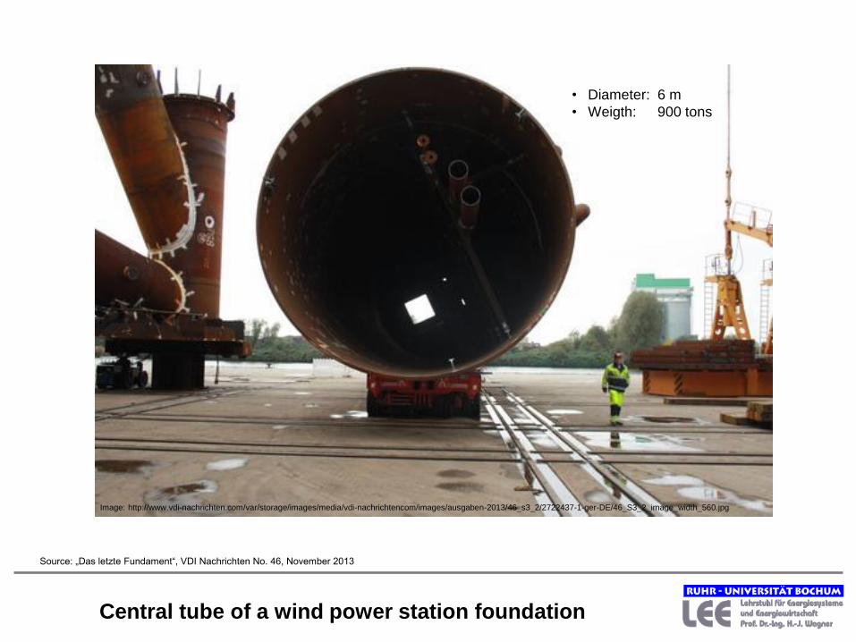
Central tube of a wind power station foundation
• Diameter: 6 m
• Weigth: 900 tons
Image: http://www.vdi-nachrichten.com/var/storage/images/media/vdi-nachrichtencom/images/ausgaben-2013/46_s3_2/2722437-1-ger-DE/46_S3_2_image_width_560.jpg
Source: „Das letzte Fundament“, VDI Nachrichten No. 46, November 2013

New devices need testing: Problems with gear boxes

Burned off wind power station in Lahr/Schwarzwald, Germany
Image: http://ais.badische-zeitung.de/piece/04/81/34/f7/75576567.jpg

Structure of my presentation
• Present status of wind energy use
• Physical and meteorological basics
• Techniques of wind converters
• Off shore windparks
• Wind use in Europe

Offshore wind projects in the German part of north and east sea
© Sonne, Wind & Wärme, 10/12

Source: Sonne, Wind und Wärme 10/2012
Offshore-wind projects in Great Britain, Ireland, France and
Netherlands

Offshore wind farm alpha-ventus: Panorama
© Doti 2009

Offshore windfarm in Denmark (Malmo-Copenhagen region)

Possible foundations of offshore wind converters
Monopile until 20 m deep of
water
Steel- or concrete
construction
Gravity foundation
until 10 m deep of
water
Steel- or concrete
construction
Tripod, Jacket
more than 20 m deep
of water
Steel construction

Repair of corrosion protection
Photo: Helmut
Müller; Sonne,
Wind und Wärme
4/2012

Fundaments for windmills for the windward Alpha Ventus
Foto: Große Boeckmann, August 2008

Jackets

Source: http://www.siemens.com/press/pool/de/pressebilder/2013/photonews/300dpi/PN201308/PN201308-
04_300dpi.jpg
Source: http://www.siemens.com/press/pool/de/pressebilder/2013/photonews/300dpi/PN201308/PN201308-
05_300dpi.jpg
Offshore windpark, transformer station

Montage of a rotor blade
Bild: http://ais.badische-zeitung.de/piece/04/81/ef/43/75624259.jpg Source: http://www.siemens.com/press/pool/de/pressebilder/2012/photonews/300dpi/PN201209/PN201209-01_300dpi.jpg

Source: http://www.siemens.com/press/pool/de/pressebilder/2012/photonews/300dpi/PN201204/PN201204-06e_300dpi.jpg
Size of rotor blades

Electricity transport from offshore to land
Source: „Germanys´s Troubled Offshore Wind Offensive“; Spiegel Online; http://cdn3.spiegel.de/images/image-395626-galleryV9-ynkq.jpg

Structure of my presentation
• Present status of wind energy use
• Physical and meteorological basics
• Techniques of wind converters
• Off shore windparks
• Wind use in Europe

Costs of a 2 MW onshore wind power station
Source: Deutsche WindGuard GmbH; Kostensituation der Windenergie an Land in Deutschland, Stand 2013
Investment plan Costs
[€/kW]
Hub height < 120 m > 120 m
Wind power station, transport,
installation 1150 1340
Foundation 70
Grid connection 70
Site development (lanes) 40
Planning, environmental
measures, concession, others 190
Total 1520 1710
Operating costs: 5,1 ct/kWh (Average over 20 years operating time)
Service, reparation, others 50 %
Rent 20 %
Management (technical and
business) 20 %
Reserve for unforeseen events 5 %
Insurance 5 %

Germany
Spain
France
Finland Sweden
Portugal
Ireland Great Britain
Latvia
Estonia
Lithuania
Poland
Romania
Bulgaria
Greece
Italy
Denmark
Netherlands
Austria
Belgium Czechia
Hungary
Slovakia
Different conveying systems for electricity (renewable energies) in the EU
Quota system
Feed in compensation
Feed in premiums
Combination of feed in compensation
and quota system
Combination of feed in
compensation and premiums
Source: Fraunhofer IST et al. ; 02/2012

Objective power station capacities in Germany 2024
(Nuclear power: 0,0%)
Photovoltaics
19%
2012 2024
Statistical value (175 GW) Objective of government (225 GW)
(Scenario B)

Renewables and liberalisation require the grid extension
europeanwide

Thank you for your attention
www.lee.rub.de