introduction - ww2.energy.ca.gov€¦ · web viewthe inverter shall consume reactive power in...
TRANSCRIPT

CEC/CPUCCEC/CPUC
Candidate DER Capabilities: Recommendations forCandidate DER Capabilities: Recommendations for Updating Technical Requirements in Rule 21Updating Technical Requirements in Rule 21
Version 1Version 199 88 , , JulyJuly AugustAugust , 2013, 2013

Contents1. Introduction.............................................................................................................................1
1.1 Scope of the Rule 21 Technical Update Project.................................................................11.2 Purpose of this Working Paper...........................................................................................11.3 Purpose and Procedures of the Smart Inverter Working Group (SIWG)............................21.4 Background........................................................................................................................ 31.5 IEEE 1547 Update Status and Relationship to This Effort...................................................51.6 Summary of DER Functions Recommendations.................................................................5
1.6.1 Phase 1a Autonomous DER Functions..................................................................61.6.2 Phase 1b Autonomous DER Functions.................................................................61.6.3 Phase 2a Communications Technologies for DER Functions...............................61.6.4 Phase 2b DER Functions Requiring Communications..........................................7
2. DER Functions to Support Grid Operations..............................................................................82.1 Hierarchical Management of DER Systems........................................................................82.2 Autonomous DER Functions and the Role of Information and Communications
Technologies (ICT)............................................................................................................102.3 Approach to Rule 21 Recommendations..........................................................................13
3. Mandated, Recommended, and Optional DER Functions......................................................153.1 Phase 1a: Key Autonomous DER Functions......................................................................153.2 Phase 1b: Additional Autonomous DER Functions...........................................................173.3 Phase 2a: Communications Technologies for DER Functions...........................................203.4 Phase 2b: DER Functions Requiring Communications......................................................213.5 Optional DER Functions....................................................................................................23
4. DER Default Setting Ranges for Phase 1a Functions...............................................................254.1 Default Voltage Ride-Through Settings............................................................................254.2 Default Frequency Ride-Through Settings........................................................................274.3 Default Volt-Var Curve Settings........................................................................................284.4 Inverter Disconnect and Reconnect Ramping and/or Timing Randomization..................30
5. Default Settings for Phases 1b, 2a, and 2b.............................................................................325.1 Default Frequency-Real Power Output............................................................................325.2 Default Dynamic Current Support Settings......................................................................33
6. Testing Plan............................................................................................................................356.1 Sources of Testing Requirements.....................................................................................356.2 Types of Tests...................................................................................................................35
Attachment A – Testing Plan for Smart Distributed Energy Resources (DER) Systems Interconnecting with Electric Power Systems........................................................................36
Candidate DER Inverter Functions Page i
Candidate DER Inverter Functions Page ii

1. Introduction
1.1 Scope of the Rule 21 Technical Update ProjectThe scope and focus of the Rule 21 Technical Update project is on developing the technical recommendations to the CPUC for capabilities of DER systems . Although the primary focus is on autonomous functions for inverter-based DER systems, some capabilities may require communications and may also apply to synchronous or induction generating units and to electric vehicle charging systems . It is understood that some DER functions may be applicable only to certain types of DER systems (e.g. frequency management requires the ability to reduce or raise real power output which may require storage capability), while others may only be cost-effective for the larger DER systems or higher penetrations of smaller DER systems.
To avoid the possible necessity to retrofit DER systems over their lifetimes, utilities may specify certain capabilities for DER systems that interconnect to their power grid, but they might not enable them or install the communication infrastructure until they become needed. For instance, basic communication capabilities may be specified but not enabled while the installation of the communication circuit is deferred until a future time. The purpose is to permit DER systems to be used for supporting utility requirements, but not to mandate that the utility actually use all DER systems all the time for those functions.
Coordination with other utility equipment and methods will be necessary; it will be a question of economics, tariffs, power engineering strategies, etc., as to which equipment and what methods are used by utilities under what conditions to ensure power system reliability, resilience, and efficiency.
1.2 Purpose of this Effort Working PaperThe purpose of this effort working paper is to develop recommendations identify for updating Rule 21: to permit certain the Distributed Energy Resources (DER) functions that must ultimately (phased in) be available for different classes of DER systems interconnected to the California distribution networks under Rule 21. Classes of DER systems may , for instance, be defined by :
T ype (e.g. inverter-based, synchronous, or induction generators, storage systems, electric vehicle chargers)
Size (e.g. <300 W, >10 MW)
Configuration (e.g. located at the PCC, aggregated behind the PCC, impacting the network at the PCC)
not currently permitted for inverter-interfaced technology and to recommend additional DER capabilities for these interconnected renewable distributed generation and energy storage systems.
The reason for these updated requirements in Rule 21 is because California Governor Brown has called for the implementation of 12,000 MW of “localized electricity generation”, namely DER, which can help the State reach its goal to acquire 33 percent of its energy from eligible renewable energy resources by 2020. High penetrations of these DER systems, located within distribution
Candidate DER Inverter Functions Page 1
grids which were designed only for handling customer loads, could adversely affect California utility operations. European experience has shown that the implementation of some DER functions can cost-effectively improve the reliability and efficiency of the power grid. The additional capabilities could include autonomous DER functions, basic communications capabilities, and emergency DER management. The European experience has also shown that waiting to implement these functions, and/or providing overly prescriptive requirements for low penetration scenarios and not anticipating higher penetration scenarios, may lead to costly upgrades and replacements. Therefore, it is critical to determine which DER functions to permit and/or recommend in a timely manner.
The recommendations, if included in the update new DER functions in of Rule 21, will allow utilities to select the DER capabilities that they require for each DER interconnection to ensure the long-term safety, reliability, and efficiency of the power grid.
1.3[1.2] Purpose and Procedures of the Smart Inverter Working Group (SIWG)In response to concerns about the current restrictions in Rule 21 on DER functionality , the Smart Inverter Working Group (SIWG) was formed in early 2013 as a joint effort between the California Energy Commission (CEC) and the California Public Utilities Commission (CPUC). The purpose of the SIWG is to explore the smart DER functionalities (primarily, but not exclusively inverter-based DER systems) which would facilitate large penetrations of distributed generation and storage into California’s grid in order to meet these renewable generation goals while maintaining high levels of system security and efficiency. This group is open to all interested parties, including utilities, DER manufacturers, integrators, and all other stakeholders. It holds calls either bi-weekly or weekly on Thursdays at 1 pm PT, depending upon the specific needs of the group. A CEC-sponsored web site ( http://www.energy.ca.gov/electricity_analysis/rule21/index.html ) provides access to documents relevant to the effort as well as the updated drafts of the documents developed by the group.
The development of this document by the SIWG was the first product of the group and recommends the new technical DER functions which should be included in Rule 21. The DER functions themselves are described in more detail in other documents, particularly in the Advanced Functions for DER Systems Modeled in IEC 61850-90-7 1 : this document only identifies which functions are recommended along with default parameters for some of the functions .
The initial draft document (version 15) was submitted to the record in June of 2013, and later discussed during the June 21, 2013 workshop to provid e a robust record for the proceeding. Comments to the document of record are to be provided by July 31, 2013 . Responses to those comments will be discussed and incorporated into new versions of this document as appropriate.
A second document, the DER Testing Plan, is also being developed by the Smart Inverter Working Group for submission to the CPUC to provide a roadmap for safety and for compliance testing of the new DER functionalities in manufacturer products. The Testing Plan identifies staggered testing schedules for different groups of functions and DER sizes, since some of the more complex
1 See “ Advanced Functions for DER Systems Modeled in IEC 61850-90-7 ” at http://collaborate.nist.gov/twiki- sggrid/bin/view/SmartGrid/IEC61850-7-420_Overview . The actual IEC 61850-90-7 Technical Report is available for purchase through the IEC.
Candidate DER Inverter Functions Page 2

inverter functions may be more difficult for some manufacturers to implement in their DER systems. Therefore, the initial implementations focus on the more critical autonomous functions for near-term implementation. The Smart Inverter Working Group has developed consensus on these autonomous functions, identified in this document as Phase 1a functions. The Testing Plan specifies these Phase 1a functions for a subset of system sizes as Group A.
The Smart Inverter Working Group is also working with testing groups , with the IEEE 1547.1a group, and with people interested in updating the UL 1741 testing and certification for California-specific requirements. The results are expected to be a set of California Smart Inverter Test Procedures that can be used for testing and certifying the manufacturer products. These California Smart Inverter Test Procedures are expected to be submitted as input to the standards organizations.
In addition, the Smart Inverter Working Group is working with communication protocol experts to define the appropriate communication requirements . This effort will also develop California Communication Test Procedures .
The results from the Smart Inverter Working Group are expected to include the following:
Recommendations for Rule 21 for additional DER technical functions, along with default settings
Testing Plan that provides a schedule with milestones for different groups of tests
Testing procedures that are coordinated with the IEEE 1547.1a efforts
UL California-specific amendment to UL 1741 for the additional functions
Communication specifications and testing procedures for the Phase 2 requirements
1.4 Scope of this EffortThe scope and focus of this effort is on autonomous capabilities of inverter-based DER systems, although some capabilities may require communications and may also apply to synchronous generating units and electric vehicle charging. It is understood that some DER functions may be applicable only to certain types of DER systems (e.g. frequency management requires the ability to reduce or raise real power output which may require storage capability), while others may only be cost-effective for the larger DER systems or higher penetrations of smaller DER systems. To avoid the possible necessity to retrofit DER systems over their lifetimes, utilities may specify certain capabilities, but not enable them or install a communication infrastructure, until they become needed. For instance, basic communication capabilities may be specified but not enabled while the installation of the communication circuit is deferred until a future time.
[1.3] BackgroundThe advent of distributed electric power production is a reality in the majority of the power systems of the world. The integration of these alternate energy sources is driven by the need for renewable energy to reduce the heavy reliance on non-renewable fossil fuels, by the increased demand for electrical energy, by the development of new technologies of small power
Candidate DER Inverter Functions Page 3

production, by the deregulation of energy markets, by the legislative incentives, and by increasing environmental constraints.
These pressures have greatly increased the demand for DER systems, leading to high penetrations of these uncoordinated sources of power. This paradigm shift in management of power systems can be characterized by the following issues:
The numbers of interconnected DER systems are increasing rapidly. The advent of decentralized electric power production is driven by many factors:
The need for new sources of energy to mitigate the heavy reliance on externally-produced fossil fuels.
The requirements in many countries and US states for renewable portfolios that have spurred the movement toward renewable energy sources such as solar and wind, including tax breaks and other incentives for utilities and their customers.
The development of new technologies of small power production that have made, and are continuing to improve, the cost-effectiveness of small energy devices.
The trend in deregulation down to the retail level, thus incentivizing energy service providers to combine load management with generation and energy storage management.
The increased demand for electrical energy, particularly in developing countries, but also in developed countries for new requirements such as Electric Vehicles (EVs).
The constraints on building new transmission facilities and increasing environmental concerns that make urban-based generation more attractive.
DER systems challenge traditional power system management. These increasing numbers of DER systems are also leading to pockets of high penetrations of these variable and uncoordinated sources of power that impact the stability, reliability, and efficiency of the power grid. DER systems must be considered as significant sources of power in system planning and operations. Their unplanned locations, their variable sizes and capabilities, and their fluctuating responses to both environmental and power situations make them difficult to coordinate, particularly as greater efficiency and reliability of the power system is being demanded.
At the same time, DER systems may be very powerful tools in managing the power system for reliability and efficiency. Local generators have been used for decades to improve the reliability of industrial facilities that have critical loads, and are often deployed in addition to local utility service. The majority of current DER systems use inverters to convert their primary form of electrical energy (often direct current (dc) or non-standard frequency) to the utility power grid standard electrical operational requirements of 60Hz or 50Hz and alternating current (ac). These inverters are controlled by software applications and therefore many of their electrical characteristics can be modified through software settings and commands. These software applications can cause the inverters to change the real power output, voltage levels, power factor, and other electrical characteristics, and can be used to improve the power system efficiency, so long as they operate within the capabilities of the DER system that they are managing and within the standard requirements for interconnecting the DER to the power system.
Candidate DER Inverter Functions Page 4

Many DER systems are becoming quite “smart” and can perform “autonomously” most of the time according to pre-established software settings. If communications capabilities are provided, they can respond to occasional commands to override or modify their autonomous actions by utilities and/or retail energy providers (REPs). In some cases, DER systems, just like bulk power generation, may be directly monitored and controlled by utilities. DER systems can be designed to include sensors that monitor local conditions of voltage levels, frequency deviations, and temperature, and can receive emergency commands and pricing signals, which allow them to modify their power and reactive power output. With the addition of communications capabilities, these autonomous settings may be updated as needed. To better coordinate these DER autonomous capabilities while minimizing the need for constant communications, utilities and REPs may also send schedules of modes and commands for the DER systems to follow on daily, weekly, and/or seasonal timeframes.
Information and Communications Technology (ICT) can provide improved coordination of DER systems. ICT is a term widely used in Europe and implies not only the communication media and protocols, but also the design and standardization of the “data objects” (data formats) and the types of information exchanges among the various utility, REP, facility systems, and DER systems. ICT capabilities, where their implementation is warranted, can provide the means to coordinate DER systems more broadly than is possible with just local autonomous control. For instance, these ICT capabilities may support the direct or indirect monitoring and control of DER systems, the issuing of emergency commands, the updating of software settings, the provision of demand response pricing signals, the establishment of schedules for energy and ancillary services, the near- real-time management of active and reactive power, and other types of utility-DER interactions. The ICT infrastructure could include private utility or REP networks, cellphone networks, utility WANs, AMI backhauls, or, for some types of information exchanges, the Internet. Cyber security is a major aspect of ICT, needed to protect the utility power system from cyber attacks, while providing privacy and confidentiality to the DER owners/operators.
1.5[1.4] IEEE 1547 Update Status and Relationship to This EffortIEEE 1547a is the update to the base IEEE 1547 of 2003. Its main purpose is to permit the DER system to actively regulate voltage at the PCC, so long as the Area EPS operator approves and this active voltage regulation does not compromise the unintentional islanding detection and disconnect function. It will also permit the high and low frequency limits of both voltage and frequency to be extended for specific time periods so that voltage and frequency ride-through by DER systems can occur.
IEEE 1547.1a on testing will also be updated to reflect the testing requirements for IEEE 1547a. Updates to UL1741 will also be undertaken. A separate document describes the recommended testing for California, based on IEEE 1547.1 but updated to reflect the new additional DER functions.
IEEE 1547.8 on high penetrations of DER is still in progress, but is expected to extend the permissive capabilities in IEEE 1547a with cover the specific recommendations for DER functions and settings in high penetration scenarios.
The IEEE standardization process necessarily takes a long time to ensure the recommendations are both appropriately constrained and yet flexible enough for utilities with very varied
Candidate DER Inverter Functions Page 5

requirements, such as the Hawaiian Islands and the congested East Coast. However, California feels it cannot wait for the completion of these standards. Therefore, it was decided that California could work in parallel with the IEEE efforts to determine the California-specific requirements.
The additional DER functions that are being recommended for inclusion in Rule 21 (see Section 3) will build on the permitted actions in IEEE 1547a and the proposed functionalities of IEEE 1547.8 by specifying the mandated and recommended functions along with ranges of settings that are appropriate for California.
1.6[1.5] Summary of DER Functions RecommendationsDetails of the DER functions are provided in Section 3.
[1.5.1] Mandatory Phase 1a Autonomous DER FunctionsIt is recommended that the following autonomous DER functions should be mandatory in Rule 21 for California as Phase 1a :
1. Support anti-islanding to trip off under extended anomalous conditions2. Provide ride-through of low/high voltage excursions beyond normal limits 3. Provide ride-through of low/high frequency excursions beyond normal limits 4. Provide volt/var control through dynamic reactive power injection through autonomous
responses to local voltage measurements5. Define default and emergency ramp rates as well as high and low limits6.[5.] Provide reactive power by a fixed power factor[6.] Reconnect by “soft-start” methods ramping and/or randomly within a preset time window
after grid power is restored
1.6.1[1.5.2] Phase 1b Autonomous DER FunctionsIt is recommended that the following autonomous DER functions should be mandatory or recommended in Rule 21 for California as Phase 1b:
1. Counteract frequency excursions beyond normal limits by decreasing or increasing real power
2.[7.] Counteract voltage excursions beyond normal limits by providing dynamic current support
[8.] Reconnect by ramping and/or randomly within a preset time window after grid power is restored
3.[9.] Limit maximum real power output at the PCC to a preset value4.[10.] Modify real power output autonomously in response to local voltage variations [11.] Provide reactive power by a fixed power factor5.[12.] Set actual real power output at the PCC6.[13.] Schedule actual or maximum real power output at specific times
Candidate DER Inverter Functions Page 6

7.[14.] Smooth minor frequency deviations by rapidly modifying real power output to these deviations
8.[15.] Follow schedules for energy and ancillary service outputs 9.[16.] Set or schedule the storage of energy for later delivery, indicating time to start
charging, charging rate and/or “charge-by” time
[1.5.3] Mandatory Phase 2a DER Functions Requiring Communications Technologies for DER FunctionsIt is recommended that the following DER functions requiring communications technologies should be mandatory for California as Phase 2a :
1. Provide capability for adding communication modules for media interfaces 2. Provide the TCP/IP internet protocols 3. Use the IEC 61850 information model for defining data exchanges 4. Support the mapping of the IEC 61850 information model to communication protocols5. Provide cyber security at the transport layer6. Provide cyber security for user and device authentication
1.6.2[1.5.4] Phase 2b DER Functions Requiring Communications It is recommended that the following communications technologies should be mandatory or recommended in Rule 21 for California as Phase 2 b :
1. Provide emergency alarms and information2.[7.] Provide status and measurements on current energy and ancillary services3.[8.] Limit maximum real power output at the PCC upon a direct command from the utility
[1.5.5] Recommended Autonomous DER FunctionsIt is recommended that the following autonomous DER functions should be included as “recommended” for California:
[1.] Smooth minor frequency deviations by rapidly modifying real power output to these deviations
[2.] Follow schedules for energy and ancillary service outputs [3.] Set or schedule the storage of energy for later delivery, indicating time to start charging,
charging rate and/or “charge-by” time
[1.5.6] Recommended DER Functions Requiring CommunicationsIt is recommended that the following DER functions requiring communications should be included as “recommended” for California:
[4.] Support direct command to disconnect or reconnect 4.[5.] Provide operational characteristics at initial interconnection and upon changes5.[6.] Test DER software patching and updates
Candidate DER Inverter Functions Page 7
[2.] DER Functions to Support Grid Operations
1.7[2.1] Hierarchical Management of DER SystemsDirect control by utilities is not feasible at this time for the thousands if not millions of DER systems “in the field”, so a hierarchical approach is necessary for utilities to interact with these widely dispersed DER systems. Most of these DER systems will be small, such as rooftop PV systems, but some may be greater than a few megawatts.
At the local level, both large and small DER systems are expected to manage their own generation and storage activities autonomously, based on local conditions, pre-established settings, and DER owner preferences. However, those DER systems that are active participants in grid operations must be coordinated with other DER systems and distribution grid devices, and thus could require communications capabilities. For simple facilities, such as a residential home, the DER controllers would provide these communications capabilities. Larger or more sophisticated customer sites would include Facilities DER energy management systems (FDEMS) that could modify these autonomous settings and issue direct commands. The distribution utilities could interact with these DER systems, through the FDEMS if it is available, to occasionally update settings, to broadcast operational or pricing signals, and/or to issue commands.
In addition, the distribution utilities must interact with regional transmission organizations (RTOs) and/or independent system operators (ISOs) for reliability and market purposes. In some regions, retail energy providers (REPs) are responsible for managing groups of DER systems.
Although in general DER systems will be part of a hierarchy, different scenarios will consist of different hierarchical levels and variations even within the same hierarchical level. For instance, small residential PV systems may not include any FDEMS or only simple FDEMS, while large industrial and commercial sites could include multiple FDEMS and even multiple levels of FDEMS. Some DER systems will be managed by Retail Energy Providers through demand response programs, while others may be managed (although not necessarily directly controlled) by utilities through financial and operational contracts or tariffs with DER owners. Some of the larger, more strategically placed DER systems, such as storage systems located in substations or large numbers of DER systems in a power plant, may be continuously controlled in real-time by the utility. For most DER installations, autonomous operations may be superseded by an external signal issued by distribution system operator, generally for emergency situations.
This hierarchical approach can be described as combinations of five levels, as illustrated in Figure12 and described briefly below.
2 Diagrams of these 5 levels have been discussed in the SGIP DRGS DEWG and the IEC TC57 WG17. They utilize the European Smart Grid Architecture Model (SGAM) structure. A White Paper can be found at https://collaborate.nist.gov/twiki-sggrid/pub/SmartGrid/DRGS/DRGS_Subgroup_B_White_Paper_-_Categorizing_Hierarchical_DER_Systems_v2.docx
Candidate DER Inverter Functions Page 8

Market
Enterprise
Operation
Station
Field
Process
Transmission Energy Market Clearinghouse
ISO/RTO/TSO Balancing Authority
Hierarchical DER System Five-Level Architecture, in SGAM Format
Level 4: Distribution Utility Operational Analysis and Control for Grid Operations
DER Management System (DERMS)
Distribution Management
System (DMS)
Outage Management
System (OMS)
System to Manage Demand Response
(DR) Pricing Signals
Transmission Bus Load
Model (TBLM)
“DER SCADA” System for Control &
Monitoring
Utility Grid
Facilities Site Loads
Circuit breaker
Meter and PCC
Level 2: Facilities DER Energy Management System (FDEMS)
Level 1: Autonomous cyber-physical DER systems
Level 5: Transmission and Market Interactions
Facilities DER Energy Management Systems
(FDEMS)
Facilities Site WAN/LAN
Utility WAN/LAN
Facilities DER Energy Management Systems
(FDEMS)
Facilities DER and LoadEnergy Management
System
PV Equipment
Electric Vehicle
PV Controller Electric Vehicle Supply Equipment
Battery Storage
Controller
Battery Diesel Generator
Diesel Controller
Distributed Energy Resources (DER) Customer PremisesTransmission Distribution
ECP ECPECPECP
Geographic Information
System (GIS)
Energy Management System (EMS)
Level 3: Utility and REP Information & Communications (ICT)
Retail Energy Provider (REP) and/or DER Aggregator
Demand Response
(DR) System
REP DER & Load Management
System
Facilities Load Management
Distribution Energy Market Clearinghouse
Retail Energy Market Clearinghouse
Figure 1: 5-Level Hierarchical DER System Architecture
1. Level 1 DER Systems (green in the Figure) is the lowest level and includes the actual cyber-physical (software plus hardware) DER systems themselves. These DER systems will be interconnected to local grids at Electrical Connection Points (ECPs)3 and to the utility grid through the Point of Common Coupling (PCC). These DER systems will usually be operated autonomously. In other words, these DER systems will be running based on local conditions, such as photovoltaic systems operating when the sun is shining, wind turbines operating when the wind is blowing, electric vehicles charging when plugged in by the owner, and diesel generators operating when started up by the customer. This autonomous operation is controlled by pre-set software values that are established at deployment, although these values may be modified locally by DER owner preferences with the concurrence of the EPS operator.
3 ECP is the point of electrical connection between the DER source of energy (generation or storage) and any electric power system (EPS). Each DER (generation or storage) unit has an ECP connecting it to its local power system; groups of DER units have an ECP where they interconnect to the power system at a specific site or plant; and a group of DER units plus local loads have an ECP where they are interconnected to the utility power system. For those ECPs between a utility EPS and a plant or site EPS, this point is identical to the point of common coupling (PCC) in the IEEE 1547, Standard for Interconnecting Distributed Resources with Electric Power Systems
Candidate DER Inverter Functions Page 9

2. Level 2 Facilities DER Management (blue in the Figure) is the next higher level in which a facility DER management system (FDEMS) manages the operation of the Level 1 DER systems. For simple facilities, such as a residential home, the FDEMS may be combined with the DER controllers, basically providing communications capabilities to the Level 1 DER systems. If a separate system, the FDEMS may be managing one or two DER systems in a residential home (e.g. a PV system and an electric vehicle). Larger FDEMS will be managing multiple DER systems in commercial and industrial sites, such as university campuses and shopping malls. Utilities may also use a FDEMS to handle DER systems located at utility sites such as substations or power plant sites.
3. Level 3 Information and Communications Technology (ICT) Infrastructure (red in the Figure) provided the information exchanges beyond the local site to allow utilities and market-based aggregators and retail energy providers (REP) to request or even command DER systems (typically through a FDEMS) to take specific actions, such as turning on or off, setting or limiting output, providing ancillary services (e.g. volt-var control), and other grid management functions. REP/aggregator requests would likely be price-based focused on greater power system efficiency, while utility commands would also include safety and reliability purposes. The combination of this level and level 2 may have varying scenarios, while still fundamentally providing the same services, including cyber security.
4. Level 4 Distribution Utility Operational Analysis (yellow in the Figure) applies to utility applications that are needed to determine what requests or commands should be issued to which DER systems. Utilities must monitor the power system and assess if efficiency or reliability of the power system can be improved by having DER systems modify their operation. This utility assessment involves many utility control center systems, including, but not limited to, Distribution Management Systems, Geographical Information Systems, Load Management Systems, Outage Management Systems, Demand Response systems, as well as DER database and management systems. Once the utility has determined that modified requests or commands should be issued, it will send these out as per Level 3.
5. Level 5 Transmission and Market Operations (purple in the Figure) is the highest level, and involves the larger utility and market environment where regional transmission operators (RTOs) or independent system operators (ISOs) may need information about DER capabilities or operations and/or may provide efficiency or reliability requests to the utility that is managing the DER systems within its domain. This may also involve the bulk power market systems, as well as market functions of retail energy providers.
1.8[2.2] Autonomous DER Functions and the Role of Information and Communications Technologies (ICT)DER systems are capable of providing many functions that support power system operations. Many of these inverter-based functions are described in the Advanced Functions for DER Systems Modeled in IEC 61850-90-74. Most DER systems can or must operate autonomously in order to
4 See “Advanced Functions for DER Systems Modeled in IEC 61850-90-7” at http://collaborate.nist.gov/twiki-sggrid/bin/view/SmartGrid/IEC61850-7-420_Overview . The actual IEC 61850-90-7 Technical Report is available
Candidate DER Inverter Functions Page 10

meet power system safety, reliability, and efficiency criteria, but communications can provide additional functionality.
In the five-level hierarchical DER architecture, at least three types of ICT architectures are envisioned:
Autonomous DER behaviour responding to local conditions with controllers focused on direct and rapid monitoring and control of the DER systems: This autonomous behaviour would use pre-set parameters and/or schedules to direct their actions, thus not needing remote communications except occasionally to update the parameters or schedules.
– Autonomous DER systems would respond “instantaneously” to locally sensed conditions. These conditions can include local measurement of voltage, frequency, and/or temperature. These pre-settings may be updated as needed (not in real-time), possibly through the Internet or through other communication methods.
– Autonomous DER systems could also be scheduled for different actions at different times of the day or week.
– Time windows can be established for different DER systems to respond randomly within that window to changing conditions, including tripping and reconnection. This prevents sudden shifts by multiple DER systems to changing conditions or schedule times.
– Both “ride-through” and anti-islanding tripping would be autonomous emergency actions.
– The DER controller would monitor and respond to local conditions, with millisecond to second reactions.
Facility DER management system (FDEMS) interactions with one or more DER systems. The FDEMS receives software application settings, utility commands, and demand-response pricing signals, and then updates DER settings to reflect that information.
– Generally, the FDEMS updates autonomous settings for each DER system. – The FDEMS may also issue direct commands to DER systems.– On start-up, the FDEMS may provide various possible autonomous settings to each of
the DER systems, and then over time modify which of these autonomous settings are active, possibly in response to utility requests or pricing signals.
– Common scenarios include a campus FDEMS coordinating many DER systems on different buildings or an energy service provider managing disparate DER systems within a community.
– Additional scenarios include an ISO/RTO managing a large storage device through Automatic Generation Control (AGC) or requesting a specific power factor at the PCC of a wind farm.
– A microgrid scenario would include a FDEMS managing the intentional islanding of the microgrid and then coordinating the generation, storage, and load elements to maintain microgrid stability through the combination of setting autonomous settings for some DER systems and issuing direct commands to other DER systems.
– Interaction frequency may be seconds to minutes, hours, or even weeks.
through the IEC.
Candidate DER Inverter Functions Page 11
Utility broadcast/multicast notifications to FDEMS or to DER systems. These notifications could be emergency commands, pricing signals, or requests for modifying DER autonomous settings.
– Generally, no direct responses from individual DER systems would be expected. If there were power system changes expected (e.g. reduced generation), these would be monitored elsewhere, such as on the feeder or in a substation. If there were financial implications to the broadcast/multicast request, the DER system responses would be determined during the smart metering, billing, and settlements process.
– Optionally, some FDEMS could aggregate DER information for use by utilities, including current and forecast energy and ancillary services capabilities.
– Critical FDEMS that manage the larger DER power plants (including virtual power plants (VPP)) and substation DER systems would interact more directly with utilities.
– One issue is uncertainly. Since broadcast/multicast can be used to request actions without necessarily knowing which DER systems can or will respond, the expectation could be that the response will need to be modelled as stochastic.
– Broadcast/multicast frequency may be hourly, weekly, or even seasonally. Emergency commands would be on an as-needed basis.
The first four (4) levels of the 5-Level hierarchical DER system architecture is shown in Figure 2 with examples of the information models (e.g. IEC 61850 and CIM) and the protocols for transporting the data defined by the models (e.g. DNP3, ModBus, and SEP 2) are shown as yellow arrows.
Candidate DER Inverter Functions Page 12

Level 4: Distribution Utility Operational Analysis and Control for Grid Operations
DER Management System (DERMS)
Distribution Management
System (DMS)
Outage Management
System (OMS)
System to Manage Demand Response
(DR) Pricing Signals
Transmission Bus Load
Model (TBLM)
“DER SCADA” System for Control &
Monitoring
Utility Grid
Facilities Site Loads
Circuit breaker
Meter and PCC
Level 2: Facilities DER Energy Management System (FDEMS)
Level 1: Autonomous cyber-physical DER systems
Facilities DER Energy Management Systems
(FDEMS)
Facilities Site WAN/LAN
Utility WAN/LAN
Facilities DER Energy Management Systems
(FDEMS)
Facilities DER and LoadEnergy Management
System
PV Equipment
Electric Vehicle
PV Controller Electric Vehicle Supply Equipment
Battery Storage
Controller
Battery Diesel Generator
Diesel Controller
ECP ECPECPECP
Geographic Information
System (GIS)
Level 3: Utility and REP Information & Communications (ICT)
Retail Energy Provider (REP) and/or DER Aggregator
REP DER & Load Management
System
Facilities Load Management
IEC 61850 over ModBus or SEP 2
Market information in OpenADR
Market information
IEC 61850 over ModBus
CIM
IEC 61850 over DNP3
Figure 2: First 4 Levels of the Hierarchical DER System Architecture Showing Communication Protocols
1.9[2.3] Approach to Rule 21 RecommendationsRegulatory requirements can take the form of mandates, recommendations, and/or permissions for the functions or actions that utilities perform. The current version of Rule 21 follows the IEEE 1547 approach of limiting the functions that DER systems can perform. However, that standard is being updated, initially to permit some functions, and eventually to provide recommendations on how those functions should be designed and executed. From the long discussions with many stakeholders on these issues, including the European examples and solutions, the draft IEEE 1547.8, and the CEC/CPUC inverter group, it has become clear that the integration requirements for DER systems is still evolving.
Given these uncertainties, a phased approach is preferred. This phased approach would permit utilities to determine the real benefits and costs of different functions, including which functions would be best applied to which DER sizes and which DER “electrical” locations. This phased approach is illustrated in Figure 3.
Candidate DER Inverter Functions Page 13

Phased Approach for Reaching the Ultimate Integration of DER Systems with Utility Operations
Autonomous DER operations Expanded
Monitoring & Control
Combined Field and Virtual Modeling and
AnalysisPartial
Integrated Operations
Ultimate fully integrated operations
Phase 1 Phase 3Phase 2 Integration
Phases: 1) Start with autonomous DER systems which provide volt/var management, low/high voltage ride-through, responses to frequency anomalies, etc. Use interconnection agreements to ensure appropriate autonomous settings.2) Expand to situational awareness with hierarchical communication networks, monitoring aggregated smaller DER and direct monitoring of larger DER. Issue broadcast requests (pricing signal and/or tariff-based) and/or direct commands3) Combine field and virtual modeling through power flow-based analysis, state estimation, contingency analysis, and other analysis applications to assess economics and reliability.4) Ultimately integrate DER management with distribution automation, load management, and demand response for optimal power system management.
Figure 3: Phased approach to integrating DER systems with utility operations
For these reasons, utilities would like to require that DER systems be capable of key functions but that not all of these functions would necessarily be activated. The utilities could then test and assess the impact of different DER functions on the reliability and efficiency of the grid, probably with different DER sizes and at different “electrical” locations.
The same philosophy would apply to communications; DER systems would be capable of information exchanges with some basic communication interface technologies included, but not all DER systems would need to communicate initially. Utilities would activate communications when their information exchange requirements are defined and when their communications network infrastructure is available. Until that time, default preset values for the activated functions would be installed at deployment, and the DER system would autonomously respond to those settings. For instance, most of the smaller DER systems could be pre-set with default values that may not need to change for many years. However, if the settings need to be updated, or new functions should be activated, or other communication capabilities are necessary, the utilities would not have to replace DER systems (as has occurred in Germany).
For this reason, the preferred approach to Rule 21 is that key DER functions, default settings for those functions, and basic communications technologies would be mandated but not necessarily activated.
Candidate DER Inverter Functions Page 14
2.[3.] Mandated, Recommended, and Optional DER Functions
DER functions that can be provided by interconnected DER systems to support grid operations are listed in the following subsections.
Phase 1 includes all the mandatory and recommended autonomous functions. Phase 1a includes the key autonomous functions, while Phase 1b includes additional autonomous functions.
Phase 2 includes the mandatory and recommended capabilities and functions that require information and communications technologies (ICT). Phase 2a covers the standards-based communication technologies required, while Phase 2b includes the DER functions that rely on communications.
The DER Functions column provides a brief description of the function.
The Description column provides additional information on the purpose and likely use of the function. This information is strictly technical; it does not address financial, regulatory, or legal issues. DER systems will only be expected to meet the requirements within their capabilities. Minimum capabilities will need to be established for specific situations.
The Communications Requirements column indicates whether the function is essentially autonomous (not requiring communications), or local (requiring some local communications such as monitoring voltage), or ICT (requiring ICT facilities with the utility or other entity for direct commands, updating settings, establishing schedules, and other information exchanges).
The M/R/O column indicates whether the DER function should be identified as mandated (M) or, recommended (R), or optional (O) in Rule 21. Mandated functions must be able to operate at least autonomously, although some functions may also require ICT capabilities. If a function is mandated, all new DER systems would be required to provide that function or capability, although the function may not be activated initially.
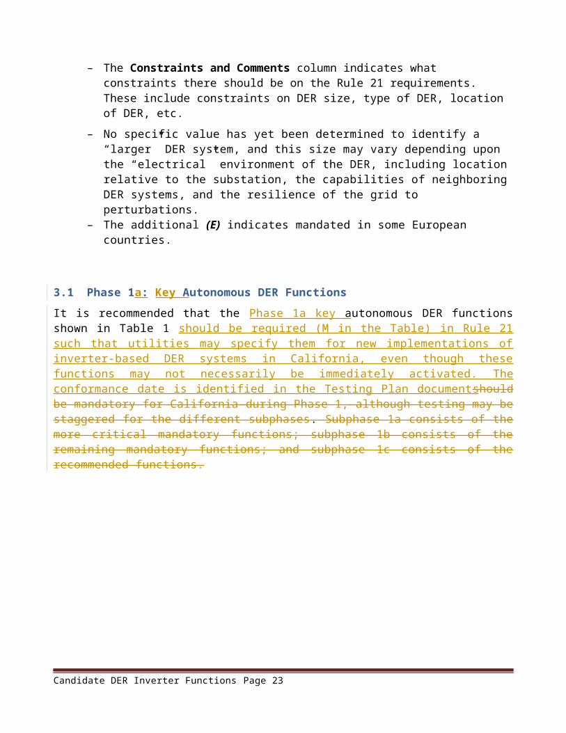
The Constraints and Comments column indicates what constraints there should be on the Rule 21 requirements. These include constraints on DER size, type of DER, location of DER, etc.
– No specific value has yet been determined to identify a “larger” DER system, and this size may vary depending upon the “electrical” environment of the DER, including location relative to the substation, the capabilities of neighboring DER systems, and the resilience of the grid to perturbations.
– The additional (E) indicates mandated in some European countries.
2.1[3.1] Phase 1a : Key Autonomous DER FunctionsIt is recommended that the Phase 1a key autonomous DER functions shown in Table 1 should be required (M in the Table) in Rule 21 such that utilities may specify them for new implementations of inverter-based DER systems in California, even though these functions may not necessarily be
Candidate DER Inverter Functions Page 15
immediately activated. The conformance date is identified in the Testing Plan document should be mandatory for California during Phase 1, although testing may be staggered for the different subphases . Subphase 1a consists of the more critical mandatory functions; subphase 1b consists of the remaining mandatory functions; and subphase 1c consists of the recommended functions.Table 1: Phase 1a Key Autonomous DER functions
Phs DER Functions Description Communication Requirements
M/R/O
Constraints & Comments
1a Support anti-islanding to trip off under extended anomalous conditions
The DER system trips off if voltage or frequency limits are exceeded over specified time periods.Although default trip-off limits settings would be implemented initially, these settings could be modifiable through agreement between the Area EPS and the DER operator.
AutonomousLocal: Monitor voltageLocal: Monitor frequency
M All DER systems(E)
1a Provide ride-through of low/high voltage excursions beyond normal limits
The DER system remains connected during voltage excursions beyond normal limits, based on extended voltage limits during specified time windows. The DER system would disconnect only when the ride-through window has expired.Although default ride-through settings would be implemented initially, these settings could be modifiable through agreement between the Area EPS and the DER operator, based on the technical capabilities of the DER system and used to possibly mitigate abrupt losses of generation.
AutonomousLocal: Monitor voltage
M All DER systems(E)
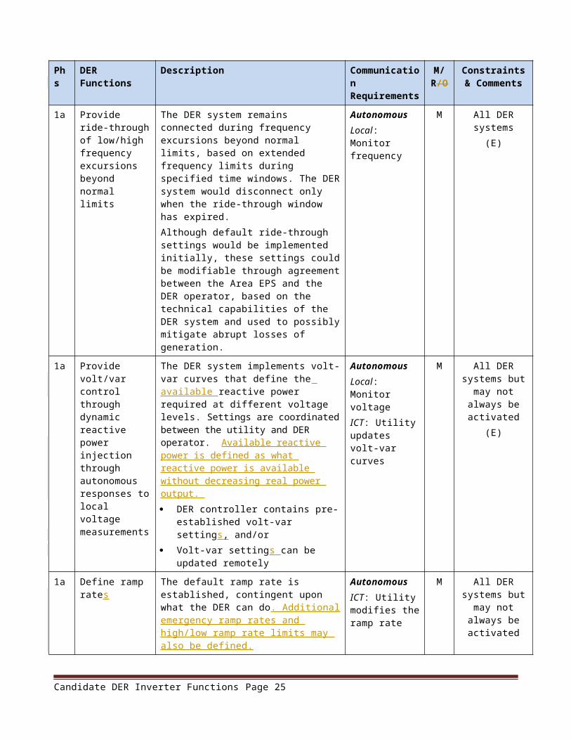
1a Provide ride-through of low/high frequency excursions beyond normal limits
The DER system remains connected during frequency excursions beyond normal limits, based on extended frequency limits during specified time windows. The DER system would disconnect only when the ride-through window has expired.Although default ride-through settings would be implemented initially, these settings could be modifiable through agreement between the Area EPS and the DER operator, based on the technical capabilities of the DER system and used to possibly mitigate abrupt losses of generation.
AutonomousLocal: Monitor frequency
M All DER systems(E)
Candidate DER Inverter Functions Page 16

Phs DER Functions Description Communication Requirements
M/R/O
Constraints & Comments
1a Provide volt/var control through dynamic reactive power injection through autonomous responses to local voltage measurements
The DER system implements volt-var curves that define the available reactive power required at different voltage levels. Settings are coordinated between the utility and DER operator. Available reactive power is defined as what reactive power is available without decreasing real power output. DER controller contains pre-established
volt-var settings , and/or Volt-var settings can be updated
remotely
AutonomousLocal: Monitor voltageICT: Utility updates volt-var curves
M All DER systems but may not
always be activated
(E)
1a Define ramp rates
The default ramp rate is established, contingent upon what the DER can do. Additional emergency ramp rates and high/low ramp rate limits may also be defined .
AutonomousICT: Utility modifies the ramp rate
M All DER systems but may not
always be activated
1a Provide reactive power by a fixed power factor
The DER system sets the inverter to the specified power factor setting: DER controller contains pre-established
power factor setting, and/or Power factor setting can be updated
remotely
AutonomousICT: Utility modifies the power factor
M All DER systems(E)
1a Reconnect after grid power is restored
The DER system reconnects to the grid after power is restored using soft-start methods such as ramping up and/or randomly turning on within a time window after grid power is restored , to avoid abrupt increases in generation. . The delay time between power restoration and the start of reconnection is preset, as are the ramping rate and the time window. , with possible ramping up and/or randomized within a time window to avoid abrupt increases in generation.
AutonomousLocal: Monitor voltageLocal: Monitor frequency
M All DER systems but may not
always be activated
(E)
2.2[3.2] Phase 1b: Additional Autonomous DER FunctionsIt is recommended that the Phase 1b additional autonomous DER functions shown in Table 2 should be required (M in the Table) or recommended (R in the Table) in Rule 21 such that utilities may specify them for new implementations of inverter-based DER systems in California, even though these functions may not necessarily be immediately activated. The required compliance date may possibly be later than the compliance date for the Phase 1a functions .
Candidate DER Inverter Functions Page 17

Table 2 : Phase 1b Additional Autonomous DER functions
Phs DER Functions Description Communication Requirements
M/R Constraints & Comments
1b Counteract frequency excursions beyond normal limits by decreasing or increasing real power
The DER system reduces real power to counteract frequency excursions beyond normal limits (and vice versa if additional generation or storage is available), particularly for microgrids. Hysteresis can be used as the frequency returns within the normal range to avoid abrupt changes by groups of DER systems.
AutonomousLocal: Monitor voltage anomaliesICT: Utility updates frequency response settings
M All DER systems but may not
always be activated
(E)
1b Counteract voltage excursions beyond normal limits by providing dynamic current support
The DER system counteracts voltage anomalies (spikes or sags) through “dynamic current support”. The DER system supports the grid during short periods of abnormally high or low voltage levels by feeding reactive current to the grid until the voltage either returns within its normal range, or the DER system ramps down, or the DER system is required to disconnect.
AutonomousLocal: Monitor voltage anomaliesICT: Utility updates dynamic current settings
M All DER systems but may not
always be activated
1b Limit maximum real power output at the PCC to a preset value
DER systems are interconnected to the grid with a preset limit of real power output to be measured at the PCC. The reason might be that the DER system is sized to handle most of the local load behind the PCC, but occasionally that load decreases below a critical level and the increased real power at the PCC may cause backflow at the substation and be a reliability concern for the utility.Most likely for larger DER systems.
AutonomousLocal: Monitor real power output at PCCICT: Utility modifies the PCC limit
M Larger DERs(E)
1b Modify real power output autonomously in response to local voltage variations
The DER system monitors the local (or feeder) voltage and modifies real power output in order to damp voltage deviations. Settings are coordinated between the utility and DER operator. Hysteresis and delayed responses could be used to ensure overreactions or hunting do not occur.
AutonomousLocal: Monitor voltageICT: Utility modifies the real power output settings
M All DER systems but may not
always be activated
Candidate DER Inverter Functions Page 18

Phs DER Functions Description Communication Requirements
M/R Constraints & Comments
1b Set actual real power output at the PCC
The utility either presets or issues a direct command to set the actual real power output at the ECP or PCC (constant export/import if load changes; constant watts if no load). The reason might be to establish a base or known generation level without the need for constant monitoring. This is the approach often used today with synchronous generators. This function is feasible only if the ICT infrastructure is available. Meter reads could provide 15-minute energy by the end of the day could provide production information for operational planning.
AutonomousLocal: Monitor real power output at PCC.ICT: utility issues a command to modify the real power output at the ECP or PCC including for charging or discharging storage systems
M Larger DERs
1b Schedule actual or maximum real power output at specific times
The utility establishes (or pre-establishes) a schedule (e.g. on-peak & off-peak) of actual or maximum real power output levels at the ECP or PCC, possibly combining generation, storage, and load management. The reason might be to minimize output during low load conditions while allowing or requiring higher output during peak load time periods.
AutonomousLocal: Monitor real power output at ECP or PCC.ICT: Utility updates the schedule of actual or maximum real power values
M Larger DERs or multiple DERs
within a facility
1b c Smooth minor frequency deviations by rapidly modifying real power output to these deviations
The DER system modifies real power output rapidly to counter minor frequency deviations. The frequency-watt settings define the percentage of real-power output to modify for different degrees of frequency deviations on a second or even sub-second basis
AutonomousLocal: Monitor frequencyICT: Utility updates the frequency-watt settings
R Recommended for all DER
systems but may not always be
activated
1b c Follow schedules for energy and ancillary service outputs
The DER system receives and follows schedules for real power settings, reactive settings, limits, modes (such as autonomous volt-var, frequency-watt), and other operational settings.
AutonomousICT: Utility, REP, or FDEMS issues schedules to DER system
R Recommended for all DER
systems but may not always be
activated
Candidate DER Inverter Functions Page 19

Phs DER Functions Description Communication Requirements
M/R Constraints & Comments
1b c Set or schedule the storage of energy for later delivery, indicating time to start charging, charging rate and/or “charge-by” time
For a DER system that has storage capabilities, such as battery storage or a combined PV + storage system or a fleet of electric vehicles. Preset time-of-charge values can be established. Settings are coordinated between the utility and DER operator. Different scenarios could include: Low load conditions at night are causing
some renewable energy to be wasted, so charging energy storage DER systems at that time makes power system operations more efficient.
DER controller charges at the specified rate (less than or equal to the maximum charging rate) until the state-of-charge (SOC) reaches a specified level.
DER controller charges at the necessary rate in order to reach the specified SOC within the “charge-by” time.
AutonomousICT: Utility updates the storage settings and/or schedule
R Recommended for DER systems
with storage capabilities
[3.3] Phase 2a : DER Functions Requiring Communications Technologies for DER FunctionsIt is recommended that the standards-based communications technologies necessary for supporting information exchanges between utilities and DER facilities and based on the requirements shown in Table 3 , should be mandatory for use by all new implementations of DER systems requiring communications in California. DER functions requiring communications shown in Table 3 Details of these communication requirements are in a separate document. The compliance date may be later than for autonomous DER functions. should be mandatory for California for Phase 2, although testing and implementations may be staggered for the different subphases. Subphase 2a consists of the communications infrastructure that is necessary for supporting information exchanges between utilities and DER facilities . Subphase 2b includes the mandatory DER functions requiring communications, while subphase 2c includes the recommended DER functions requiring communications.
Candidate DER Inverter Functions Page 20
Table 3: DER Functions requiring Standards-based communications technologies requirements
Phs DER Functions Description Communication Requirements
M/R/O
Constraints & Comments
2a Provide capability for adding communication modules for media interfaces
Standard interfaces can connect to different wired and/or wireless media. These media could include utility wireless systems, cellphone GPRS, customer WiFi network, and the Internet.Utilities would specify which communication interface modules are required for specific implementations.
ICT: Provide communications between the DER system and the utility (possibly through the customer’s FDEMS)
M The ability to communicate is mandatory, but
no specific media is mandated
2a Provide the TCP/IP internet protocols
Basic Internet transport layer standards of TCP/IP, in particular an IP address.
ICT: Use common transport layer protocols
M IP address is required.
Possibly IPv6 address?
2a Use the IEC 61850 information model for defining data exchanges
Abstract information models for DER systems should use the IEC 61850-7-420 and IEC 61850-90-7 for DER systems.
ICT: Use interoperable data models, even if mapped to different protocols
M Require international standards for information
models
2a Support the mapping of the IEC 61850 information model to communication protocols
DER systems should support the ability to map the abstract IEC 61850 information model to standard protocols, such as ModBus, DNP3 (IEEE 1815), IEC 61850 (MMS), SEP 2.0, etc.The default protocol that must be supported for communications with a utility is secure DNP3 (IEEE 1815:2012). This protocol may be used between a facility gateway and the utility. The communications between the facility gateway and the DER systems may use other protocols. This gateway may be provided by the DER owner or by the utility for a fee, reflecting the most economical arrangement.
ICT: Permit different protocol mappings
M The ability to map from the IEC
61850 information
model to protocols is
required. Secure DNP3 (IEEE
1815:2012) is mandated for
communications with the utilities, possibly through a facility gateway
2a Provide cyber security at the transport layer
Cyber security at the transport layer should be provided, such as Transport Layer Security (TLS) or IEEE 802.11i.
ICT: Provide transport layer cybersecurity
M TLS provides easily
implemented standard
cybersecurity
Candidate DER Inverter Functions Page 21
Phs DER Functions Description Communication Requirements
M/R/O
Constraints & Comments
2a Provide cyber security for user and device authentication
Cyber security for user and device identification and authentication should be provided, based on user passwords, device security certificates, and role-based access control. Confidentiality is optional. Public Key Infrastructure (PKI) could be used for key management.Reference external documents on DER cyber security (ISA .99, NISTIR 7628, DER cyber security in SGIP DRGS DEWG)
ICT: Require user and device authentication
M All access to DER systems should
include authenticationReference an
external document on
DER cyber security
2.3[3.4] Phase 2b: DER Functions Requiring CommunicationsIt is recommended that the Phase 2 b DER functions requiring communication shown in Table 4 should be required (M in the Table) or recommended (R in the Table) in Rule 21 such that utilities may specify them for new implementations of inverter-based DER systems in California, even though these functions may not necessarily be immediately activated. The required compliance date may possibly be later than the compliance date for the Phase 1a functions.Table 4 : DER functions requiring communications
Phs DER Functions Description Communication Requirements
M/R Constraints & Comments
2b Provide emergency alarms and information
The DER system (and aggregations of DER systems, such as virtual power plants) provides alarms and supporting emergency information via the FDEMS to the utility. This function is feasible only if the ICT infrastructure is available.
ICT: DER system provides alarms and emergency information to utility and/or REP
M Larger DERs or multiple DERs
within a facility
2b Provide status and measurements on current energy and ancillary services
The DER system (and aggregations of DER systems, such as virtual power plants) provides current status, power system measurements, and other real-time data (possibly aggregated via the FDEMS) to the utility, in order to support real-time and short-term analysis applications. This function is feasible only if the ICT infrastructure is available. (Revenue metering data is provided via alternate means.)
ICT: DER system provides status and measurement values to utility and/or REP
M Larger DERs or multiple DERs
within a facility
Candidate DER Inverter Functions Page 22
Phs DER Functions Description Communication Requirements
M/R Constraints & Comments
2b Limit maximum real power output at the PCC upon a direct command from the utility
The utility issues a direct command to limit the maximum real power output at the ECP or PCC. The reason might be that unusual or emergency conditions are causing reverse flow into the feeder’s substation or because the total DER real power output on the feeder is greater than some percentage of total load. The command might be an absolute watt value or might be a percentage of DER output. This function is feasible only if the ICT infrastructure is available. It might also be used to ensure fairness across many DER systems.
ICT: Utility issues a command to limit the real power output at the ECP or PCC
M Larger DERs or large groups of DERs where ICT capabilities are
available
2b c Support direct command to disconnect or reconnect
The DER system performs a disconnect or reconnect at the ECP or PCC. Time windows are established for different DER systems to respond randomly within that window to the disconnect and reconnect commands. This function is feasible only if the ICT infrastructure is available.
ICT: Utility or FDEMS issues disconnect or reconnect command
R Recommended for all DER
systems but may not always be activated and would require ICT capabilities
2b c Provide operational characteristics at initial interconnection and upon changes
The DER system provides operational characteristics after its “discovery” and whenever changes are made to its operational status.
Off-line or ICT: (may be prior to installation) Provide DER characteristics information to utility
R Recommended for DER systems.
Since communications
capability is mandatory, can be added later
2b c Test DER software patching and updates
Initial DER software installations and later updates are tested before deployment for functionality and for meeting regulatory and utility requirements, including safety. After deployment, testing validates the DER systems are operating correctly, safely, and securely.
Off-line, local, or ICT: (may be prior to installation or handled locally) Test DER software
R Recommended for all DER
systems, using appropriate
types of testing
2.4[3.5] Optional DER Functions The following DER functions shown in Table 5 should be optional for California. No explicit testing plan is therefore identified for these functions.
Candidate DER Inverter Functions Page 23
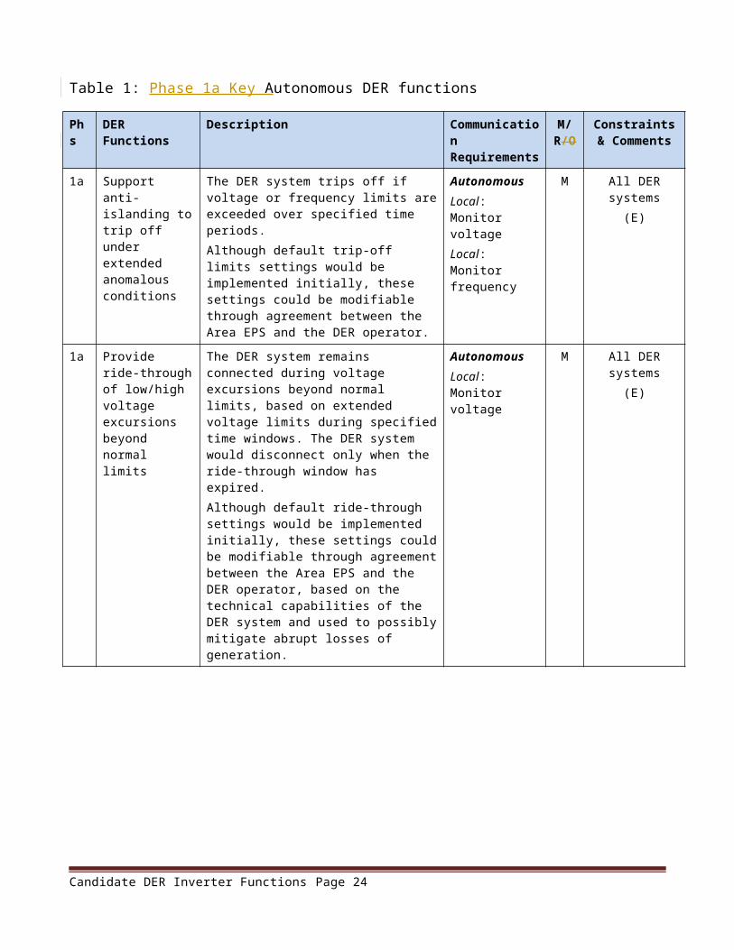
Table 5: Optional DER Functions
DER Functions Description Communication Requirements
M/R/O
Constraints & Comments
Provide backup power after disconnecting from grid
The DER system, including energy storage and electric vehicles, has the ability to provide real power when the site is disconnected from grid power. The reason is for providing backup power to the facility and possibly black start capabilities.
AutonomousLocal: Monitor voltage, frequency, and connected load
O Decision by the DER owner/manager
Provide reactive power through autonomous responses to weather, current, or time-of-day
The DER system implements temperature-var curves that define the reactive power for different ambient temperatures, similar to use of feeder capacitors for improving the voltage profile. Curves could also be defined for current-var and for time-of-day-var.
AutonomousLocal: Monitor weather conditionsICT: Utility updates xx-var curves
O Utilities may optionally identify some DER systems that could provide this functionality,
with agreement by DER owner/manager
Create microgrid (pre-designed)
After grid power is lost or disconnected, or upon command, the DER system enters into microgrid “mode” as either “leading” or “following” the microgrid frequency and voltage, while acting either as base generation or as load-matching, depending upon preset parameters.
AutonomousICT: Utility or FDEMS issues “microgrid mode” command
O Optional decision by DER owners/
managers if the DER systems have been
designed to support microgrid
operations
Provide low cost energy
Utility, REP, or FDEMS determines which DER systems are to generate how much energy over what time period in order to minimize energy costs. Some DER systems, such as PV systems, would provide low cost energy autonomously, while storage systems would need to be managed.
Autonomous for renewablesICT: Utility or REP issues real power output requirement to other DER systems
O Optional, market driven, and based on capabilities of the DER systems
Provide low emissions energy
Utility, REP, or FDEMS determines which non-renewable DER systems are to generate how much energy in order to minimize emissions. Renewable DER systems would operate autonomously.
Autonomous for renewablesICT: Utility or REP issues real power output level to other DER systems
O Optional, market driven, and based on capabilities of the DER systems
Provide renewable energy
Utility, REP, or FDEMS selects which non-renewable DER systems are to generate how much energy in order to maximize the use of renewable energy. Renewable DER systems would operate autonomously.
Autonomous for renewablesICT: Utility or REP issues real power output level to other DER systems
O Optional, market driven, and based on capabilities of the DER systems
Candidate DER Inverter Functions Page 24
DER Functions Description Communication Requirements
M/R/O
Constraints & Comments
Scheduled, planned, or forecast of available energy and ancillary services
The FDEMS provides scheduled, planned, and/or forecast information for available energy and ancillary services over the next hours, days, weeks, etc., for input into planning applications. Separate DER generation from load behind the PCC. This function is feasible only if the ICT infrastructure is available.
ICT: FDEMS provides information to utility and/or REP
O Optional, market driven, and based on capabilities of the DER systems
Issue generation and storage schedules
The DER system provides schedules of expected generation and storage reflecting customer requirements, maintenance, local weather forecasts, etc. This function is feasible only if the ICT infrastructure is available.
ICT: Provide scheduling information to Utility, REP, or FDEMS
O Optional, and may not always be
activated
Provide black start capabilities
The DER system operates as a microgrid (possibly just itself) and supports additional loads being added, so long as they are within its generation capabilities. This function is feasible only if the ICT infrastructure is available.
ICT: Utility issues “black start mode” command
O Optional, market driven, and based on capabilities of the DER systems
Support frequency regulation by direct automatic generation control (AGC) commands
The DER system (or aggregations of DER systems) implements modification of real-power output based on AGC signals on a multi-second basis. This function is feasible only if the ICT infrastructure is available.
ICT: Utility issues AGC commands to modify real power output
O Utilities may optionally identify some DER systems that could provide this functionality,
with agreement by DER owner/manager
Provide “spinning” or operational reserve as bid into market
The DER system provides emergency real power upon command at short notice (seconds or minutes), either through increasing generation or discharging storage devices. This function would be in response to market bids for providing this reserve. This function is feasible only if the ICT infrastructure is available.
ICT: Utility issues command for emergency reserve
O Optional, market driven, and based on capabilities of the DER systems
Manage real power output based on demand response (DR) pricing signals
The DER system receives a demand response (DR) pricing signal from a utility or retail energy provider (REP) for a time period in the future and determines what real power to output at that time. This function is feasible only if the ICT infrastructure is available.
ICT: Utility or REP issues DR pricing signal
O Optional, market driven, and based on capabilities of the DER systems
Candidate DER Inverter Functions Page 25

DER Functions Description Communication Requirements
M/R/O
Constraints & Comments
Manage selected ancillary services based on demand response (DR) pricing signals
The DER system receives a DR pricing signal from a utility or retail energy provider (REP) for a time period in the future and determines what ancillary services to provide at that time. This function is feasible only if the ICT infrastructure is available.
ICT: Utility or REP issues DR pricing signal
O Optional, market driven, and based on capabilities of the DER systems
Initiate automated “discovery” of DER systems
The DER system supports its automated “discovery” as interconnected to a location on the power system and initiates the integration process.This function is feasible only if the ICT infrastructure is available. Otherwise, manual methods must be used.
Off-line or ICT: Utility, REP, or FDEMS “discovers” a new or moved DER system
O Optional for DER systems. Since
communications capability is
mandatory, can be added later
3.[4.] DER Default Setting Ranges for Phase 1 a Functions
3.1[4.1] Default Voltage Ride-Through SettingsThe limits shown in Table 6 and illustrated in Figure 4 define both time-voltage areas in which the DER must disconnect (as it does now) and an area within which it must not disconnect (for disturbance ride-through). The goal of defining these areas should be that most DERs would ride through most transmission faults and disconnect for most nearby distribution faults. The voltage level is indicated as the percentage above or below nominal voltage, which is defined as 1.00. The limits (Lim) are noted in the figure.
Different set points should be permitted with agreement of the generator and the EPS operator, but the default values proposed should work in most cases.
Earlier disconnection should be permitted if necessary for generator protection. These step-like curves could be replaced with straight lines or other curve shapes.
Requirement: Inverters shall stay connected to the electric grid, and shall disconnect from the electric grid during a high or low voltage event, in compliance with the parameters shown in Table 6.
Table 6: Default voltage ride-through settings
Lim Voltage Level Stay Connected Until Lim Voltage level Disconnect by
c >1.17 0.1 sec d >1.2 0.16
c 1.07-1.17 12 sec. d 1.1 - 1.2 13 sec
0.92-1.07 Indefinite 0.88 – 1.1 Do not disconnect
b 0.7 – 0.92 20 sec a 0.6 – 0.88 21 sec
Candidate DER Inverter Functions Page 26

b 0.5 – 0.7 10 sec a 0.45 – 0.6 11 sec
b 0 – 0.5 0.1 sec (2??) a 0 – 0.45 0.16 sec (2.5??)
0%
10%
20%
30%
40%
50%
60%
70%
80%
90%
100%
110%
120%
130%
140%
Volta
ge
Time (1 sec/div.)
EXISTING AND RECOMMENDED VOLTAGE RIDE THROUGH
EXISTING IEEE-1547
LIMIT d
LIMIT c
EXISTING IEEE-1547
LIMIT a
LIMIT b
Figure 4: Graph of default voltage ride-through settings (black curves are existing limits, green curves are “stay connected”, and red curves are disconnect)
3.2[4.2] Default Frequency Ride-Through SettingsThere is no system benefit for having a distributed generating resource disconnect during under frequency conditions before 57 Hz when most conventional resources will have disconnected. (For an island system like Hawaii or Catalina, even this may be reduced to 56 Hz.) For over frequency conditions, it is believed that system stability would be enhanced by ramping DER output from maximum near 60 Hz to zero near 61 Hz (and back up again as frequency decreases).Care should be taken that in attempting to facilitate disturbance ride-through, frequency based anti-islanding features are not compromised.Faults will cause temporary phase shifts and changes to zero crossing times which may be misinterpreted as frequency change. DER control and protection systems should be designed to discriminate between these events and act appropriately.
Requirement: Inverters shall accommodate, at a minimum, underfrequency and overfrequency operation in compliance with the WECC Off-Nominal Frequency Load Shedding Plan, as provided in Table 7. In general the inverter would not trip off line at any frequency greater than 57 Hz or less than 60.3 Hz.
Candidate DER Inverter Functions Page 27

Table 7: WECC Off Nominal Frequency Load Shedding Limits
Underfrequency Limit Overfrequency Limit Minimum Time*>59.4 Hz < 60.6 Hz N/A (continuous operation)≤59.4 Hz ≥60.6 Hz 3 minutes≤58.4 Hz ≥61.6 Hz 30 seconds≤57.8 Hz 7.5 seconds≤57.3 Hz 45 cycles≤57.0 Hz ≥61.7 Hz Instantaneous trip
* Minimum Time is the time the inverter should stay interconnected with the PV generator power being supplied to the grid.
Alternative: Alternative values to the WECC load shedding limits are shown in Table 8 and Figure5. These values provide default interconnection system response to abnormal frequencies as proposed for IEEE 1547a. The frequency trip points are optionally adjustable by authorized personnel for DER systems below 300W and required for DER systems above that size. Microgrids may need different default frequency settings, using the setting group concept.
Table 8: Default interconnection system response to abnormal frequencies (IEEE 1547a)
System frequency Default frequency settings (Hz)
Range of adjustability (Hz)
Default clearing time (s)
Range of adjustability (s)
f < 57.0 57 53 - 59 0.16 0 - 257.0 < f < 60.0 58.5 53 - 60 2 0 – 300 (or 600
for islands)60.0 < f < 61.5 60.5 60 - 62 2 0 - 30060.2 < f < 61.5 DER power reduction permitted
f > 61.5 62 60 - 66 2 0 - 300
Candidate DER Inverter Functions Page 28

Figure 5: Proposed frequency parameters in IEEE 1547a
3.3[4.3] Default Volt-Var Curve SettingsRequirement: The inverter shall be capable of operating in the following reactive power modes:
Dynamic power factor: Inverter shall be capable of operating dynamically within a power factor range of +/- .1 PF. The figure below illustrates this power factor range. Inverter will more typically be operating within a power factor range of +/-.8 PF.
Figure 6: P-Q capability curve
Dynamic VAR output or input:
Candidate DER Inverter Functions Page 29
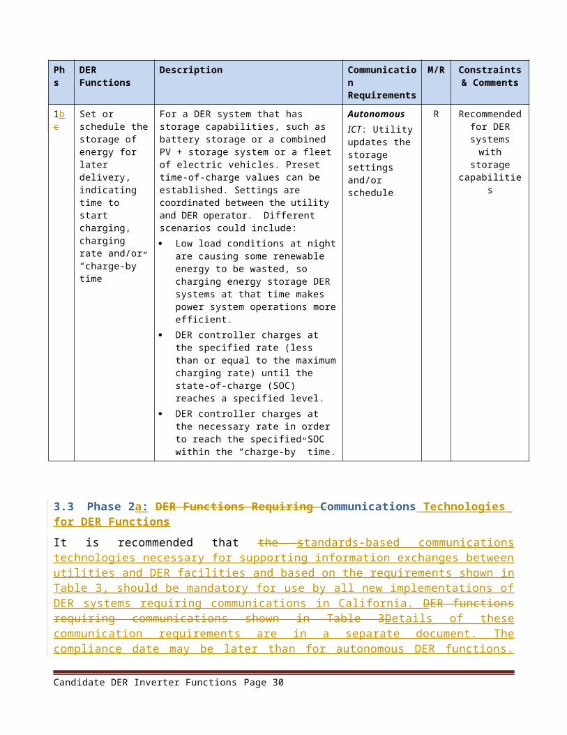
– Inverter shall autonomously prevent line voltage changes from exceeding 2% at the point of common coupling (PCC) due to a loss of generation, or due to an increase in generation output. Inverter output shall not cause the line voltage at the point of common coupling to go outside the requirements of the latest version of ANSI C84.1, Range A.
– Dynamic VAR output/input function shall not operate within a total deadband of 2% (i.e. a range of +/-1%) of line voltage at the PCC.
Autonomous operations described above may be superseded by an external signal issued by distribution system operator.
Requirement: The reactive power output of the inverter shall be dynamic and adjustable. The default time responses shall be multi-second to avoid problems with anti-islanding mechanisms although shorter time responses could be mutually agreed to . Hysteresis may also be included to avoid hunting or rapid direction changes. It shall be possible to provide the prescribed reactive power compensation within the following time constraints:
Within 10 seconds if reactive power setting is prescribed by autonomous control
Within 5 seconds if reactive power setting is prescribed by external signal which will supersede autonomous settings.
No change in reactive compensation shall occur unless the voltage changes outside the deadband range of 2% (+/-1%)
Requirement: The inverter shall consume reactive power in response to an increase in line voltage, and generate reactive power in response to a decrease in line voltage. In general, a curve shall be established that correlates changes in line voltage to reactive power output. In Figure 7, the volt-var curve indicates the percentage of available reactive power for the measured percentage of the reference voltage.
VA
Rs
Gen
erat
ed
System Voltage
Voltage-Rising/FallingP1 (V = 97%VRef, Q = 50%VArAval)
P2 (V = 99%VRef, Q = 0%VArAval)
P3 (V = 101%VRef, Q = 0%VArAval)
P4 (V = 103%VRef, Q = -50%VArAval)
Example settings for providing % of available vars
Inductive/Underexcited
Capacitive/Overexcited
Figure 7: Volt-var mode – available vars mode
Candidate DER Inverter Functions Page 30

Requirement: Although different values may be selected, the default volt-var settings are shown in Table 9.
Table 9: Default Volt-Var Settings
Voltage Array (% VRef)
VAr Array (% VArAval)
V1 97 Q1 50
V2 99 Q2 0
V3 101 Q3 0
V4 103 Q4 50
Settings Default Values
VAr Ramp Rate Limit – fastest allowed decrease in VAR output in response to either power or voltage changes
50 [%VArAval/s]
VAr Ramp Rate Limit – fastest allowed increase in VAR output in response to either power or voltage changes
50 [%VArAval/s]
The time of the PT1 in seconds (time to accomplish a change of 95 %).
10 s
Randomization Interval – time window over which mode or setting changes are to be made effective
60 s
3.4[4.4] Inverter Disconnect and Reconnect Ramping and/or Timing RandomizationRequirement: If voltage limits are exceeded and inverter disconnection is imminent, disconnection shall employ timing randomization so that multiple inverters do not disconnect simultaneously for the same system voltage disturbance. And after such disconnection, inverters shall reconnect using ramping or timing randomization to avoid multiple inverters connecting simultaneously after a system disturbance.
Default ramping values may be preset based on the inverter capabilities and mutually agreed rates.
The randomization of timing for disconnection and reconnection scenarios shall be:
Disconnection: If voltage limits are exceeded, inverters shall disconnect at a random time during a window of an additional 0 to 10% beyond the elapsed time from initial fault.
Reconnection: After an inverter has disconnected due to a system disturbance, it will reconnect at a random time during a window of an additional 0 to 10 seconds beyond the earliest allowable reconnection time.
Candidate DER Inverter Functions Page 31

4. Default Setting s for Phase s 1b , 2a, and 2b
These sections will require additional content, review , and update before the se functions are implemented .
4.1 Default Frequency-Real Power OutputTable 10 and Figure 8 are extracted from “Advanced Functions for DER Systems Modeled in IEC 61850-90-7”) and illustrate possible default settings for real power output decreases for high frequency levels. Figure 9 illustrates the use of hysteresis to minimize hunting and over-responses by multiple DER systems.
Table 10: Default frequency-watt curve settings
Name Description Default settings
WGra The slope of the reduction in the maximum allowed watts output as a function of frequency
40 % PM/Hz
HzStr The frequency deviation from nominal frequency (ECPNomHz) at which a snapshot of the instantaneous power output is taken to act as the “capped” power level (PM) and above which reduction in power output occurs
0.2 Hz
HzStop The frequency deviation from nominal frequency (ECPNomHz) at which curtailed power output may return to normal and the cap on the power level value is removed.
0.05 Hz
HysEna A boolean indicating whether or not hysteresis is enabled
On
HzStopWGra The maximum time-based rate of change at which power output returns to normal after having been capped by an over frequency event.
10 % WMax/minute
Candidate DER Inverter Functions Page 32

Figure 8: Frequency-based active power reduction
(% o
f WR
ef)
Figure 9: Example array settings with hysteresis
4.2[4.5] Default Dynamic Current Support SettingsFor counteracting voltage excursions beyond normal limits, dynamic current support can be provided. Figure 10 (extracted from “Advanced Functions for DER Systems Modeled in IEC 61850-90-7”) indicates the types of settings that would need to be defined. The triggering of this function also requires settings – more details can be found in the same document.
Candidate DER Inverter Functions Page 33

Figure 10: Basic concepts of the dynamic reactive current support function
[4.6] Randomization of Inverter Disconnect and Reconnect Requirement: If voltage limits are exceeded and inverter disconnection is imminent, disconnection shall employ timing randomization so that multiple inverters do not disconnect simultaneously for the same system voltage disturbance. And after such disconnection, inverters shall reconnect using timing randomization to avoid multiple inverters connecting simultaneously after a system disturbance.The randomization of timing for disconnection and reconnection scenarios shall be:
Disconnection: If voltage limits are exceeded, inverters shall disconnect at a random time during a window of an additional 0 to 10% beyond the elapsed time from initial fault.
Reconnection: After an inverter has disconnected due to a system disturbance, it will reconnect at a random time during a window of an additional 0 to 10 seconds beyond the earliest allowable reconnection time.
[4.7] Default Frequency Smoothing SettingsTBD
[4.8] Security for CommunicationsRequirement: The DER systems shall have communications capabilities and security control mechanism that comply with all applicable System Requirements (SRs) of standard ISA 99.03.03 for Security for Industrial Automation and Control Systems: System Security Requirements and
Candidate DER Inverter Functions Page 34

Security Assurance Levels, Draft 2, Edit 30, published September 2010. It is also desirable (but not required) that the inverter and its associated computing components shall be ISA-099 certified/accredited.
In general, DER systems shall be hardened to prohibit unnecessary functions, ports, protocols and/or services. DER systems shall be securely provided with security certificates from authorized Certificate Authorities which can be used to authenticate the device. These security certificates shall be provided initially by the manufacturer and subsequently whenever the DER systems’ role changes. All information exchanges shall ensure the authenticity of both the sender and the receiver. Communications integrity, including tamper detection, replay prevention, and reasonability checking, shall be ensured for all information exchanges. Confidentiality of selected information exchanges shall be supported. Role-based access control shall be used to define the rights and privileges of all users accessing the DER systems. User passwords shall be securely stored and transmitted. All events, including security-related events, shall be logged with an accurate timestamp. This audit log shall also be secured against unauthorized modification and shall be available to authorized users. On loss of communications for an extended period, DER systems shall enter a predefined default state.
Candidate DER Inverter Functions Page 35

5. Testing Plan
Testing is critical to ensure the safety and reliability of the grid. A separate document called “Testing Plan for Smart Distributed Energy Resources (DER) Systems Interconnecting with Electric Power Systems” covers the detailed testing plan and will become Attachment A to this document. The following sections provide a summary of testing sources and types of tests.
5.1 Sources of Testing Requirements Tests should cover all mandatory and recommended DER functions that are specified in Rule
21, including any mandatory information and communications technologies
IEEE 1547.1 should be used as a source for updating California testing requirements for the specified functions, but cannot wait for 1547.1a. However, coordination with that update process will be critical.
UL 1741 should be used as source for safety testing requirements. California could potentially work with UL to update these safety requirements to cover the specified functions.
5.2 Types of Tests Vendor factory software tests for product functionality, performance, and basic
communications before the products are released for external product testing.
External product testing would provide independent assessment of product capabilities and conformance to specifications. This testing could be done by NREL, SunSpec Alliance, TÜV Rhineland, DOE SunShot, Sandia, or other testing facility. Combinations of these testing facilities could be used, depending upon the purposes of the testing, funding levels, etc.
Internal utility bench testing can be used to ensure products meet utility-specific requirements.
Site tests can cover proper operation in the field once the DER systems are installed. These may include on-going testing and experimenting with different settings for the functions.
Vendor interoperability tests may come later when the complete suite of information and communications technologies (ICT) are specified.
Candidate DER Inverter Functions Page 36
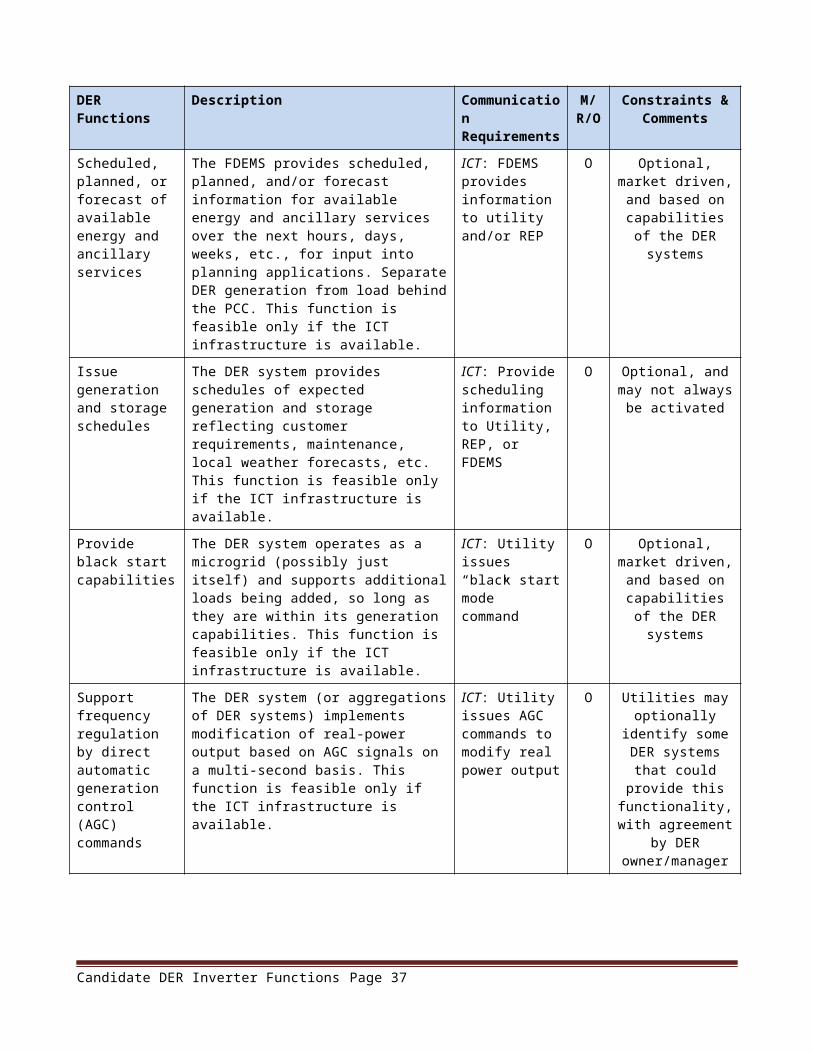
Attachment A – Attachment A – Testing Plan for Smart Distributed EnergyTesting Plan for Smart Distributed Energy Resources (DER) Systems Interconnecting with Electric PowerResources (DER) Systems Interconnecting with Electric Power
SystemsSystems{See separate document}
Candidate DER Inverter Functions Page 37