introduction - youth4work
TRANSCRIPT

MULTI-PURPOSE OPERATION MACHINE
TIT ADVANCE 1
INTRODUCTION

MULTI-PURPOSE OPERATION MACHINE
TIT ADVANCE 2
Introduction Manufacturing industries are basically meant for production of useful goods and services at low
cost. All the tasks in everyday lives have been made quicker due to technological advancements.
However, this advancement also demands huge investments and expenditure. In view of this, every
industry desires to achieve a high productivity rate while maintaining the quality and standard of
the product at a low cost. The idea behind this project is to develop a conceptual machine tool
which would be capable of performing different operations simultaneously while also being
economically efficient. Machining is one of the processes of manufacturing in which the specified shape to any work piece
is imparted by removing the surplus material. Conventionally, this surplus material from the
workpiece is removed in the form of chips by interfacing the workpiece with an appropriate tool.
The process of chip formation during metal cutting is affected by relative rotatory or translator
motion between a tool and the workpiece achieved with the aid of a device called machine tool. A machine tool is a machine for shaping or machining metal or other materials, usually by cutting,
boring, grinding, shearing, or other forms of deformation. Machine tools usually employ some
types of tools that do the cutting or shaping. All machine tools have a means of constraining the
workpiece and as well as providing a guided movement of the different parts of the machine. Thus,
the relative movement between the workpiece and the cutting tool which is called the tool-path is
controlled or constrained by the machine to at least some extent, rather than being entirely offhand
or freehand. The proposed synchronous machine tool will have different work-stations which will be capable of
carrying out a series of machining operations on the same machine which would otherwise require
several machines in order to perform the same machining operations the purpose of this paper is to
design and construct a low capital synchronous operation machine tool for the machine shop of the
college of engineering at Jazan University, Kingdom of Saudi Arabia. The idea behind this project
is to teach designing and other analytical skills in order to train individuals or students to find
solutions to difficulties they may encounter during real engineering problems. This project also
offers the future scope to make more complex variations of the machine tool for different
engineering requirements.

MULTI-PURPOSE OPERATION MACHINE
TIT ADVANCE 3
LITERATURE
REVIEW
MULTI-PURPOSE OPERATION MACHINE
TIT ADVANCE 4
Literature Review
Before starting our work, we have undergone through many research papers which indicates that for a production based industries machine installation is a tricky task as many factor
being associated with it such as power consumption (electricity bill per machine), maintenance cost, no of units produced per machine i.e. capacity of machine, time consumption and many
more…. Some research papers which have led us to approach to the idea of a machine which may
give solution to all these factors are as follows: Heinrich Arnold1 November 2001[1]: Rather long re-investment cycles of about 15 years have
created the notion that innovation in the machine tool industry happens incrementally. But looking
at its recent history, the integration of digital controls technology and computers into machine tools
have hit the industry in three waves of technology shocks. Most companies underestimated the
impact of this new technology. This article gives an overview of the history of the machine tool
industry since numerical controls were invented and introduced and analyzes the disruptive
character of this new technology on the market. About 100 interviews were conducted with
decision-makers and industry experts who witnessed the development of the industry over the last
forty years. The study establishes a connection between radical technological change, industry
structure, and competitive environment. It reveals a number of important occurrences and
interrelations that have so far gone unnoticed.
Dr. Toshimichi Moriwaki (2006) [2] Ref.: Recent trends in the machine tool technologies are surveyed from the viewpoints of high speed and high performance machine tools, combined
multifunctional machine tools, ultra-precision machine tools and advanced and intelligent control technologies. Frankfurt-am Main, 10 January 2011: The crisis is over, but selling machinery remains a tough
business. Machine tools nowadays have to be veritable “jack of all trades”, able to handle all kinds of materials, to manage without any process materials as far as possible, and be capable of adapting to new job profiles with maximized flexibility. Two highly respected experts on machining and forming from Dortmund and Chemnitz report on what‟s in store for machine tool manufacturers and users.
Multi-purpose machines are the declarations of independence. The trend towards the kind
of multi-purpose machining centers that are able to cost efficiently handle a broad portfolio of products with small batch sizes accelerated significantly during the crisis. “With a multi-purpose machine, you‟re less dependent on particular products and sectors”, explains Biermann
MULTI-PURPOSE OPERATION MACHINE
TIT ADVANCE 5
I. Proposed Methodology In this project, we will generally give the power supply to the shaft on which a bevel gear is
mounted on it, and a second bevel gear at a right angle to it has been mounted on a drill shaft to
which a drill bit is being attached. At one end of the shaft is connected to power supply, other end
is being joined to a circular disc, through this circular disc scotch yoke mechanism is being
performed (rotator y motion is converted to reciprocating motion). Also in between these two, a
helical gear is mounted which transfer its motion to other helical gear which is mounted on a shaft
consist of grinding wheel
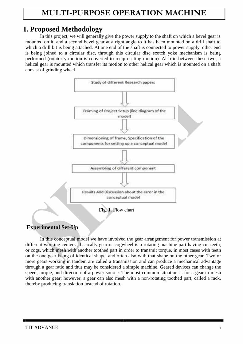
Fig. 1. Flow chart
Experimental Set-Up
In this conceptual model we have involved the gear arrangement for power transmission at
different working centers , basically gear or cogwheel is a rotating machine part having cut teeth,
or cogs, which mesh with another toothed part in order to transmit torque, in most cases with teeth
on the one gear being of identical shape, and often also with that shape on the other gear. Two or
more gears working in tandem are called a transmission and can produce a mechanical advantage
through a gear ratio and thus may be considered a simple machine. Geared devices can change the
speed, torque, and direction of a power source. The most common situation is for a gear to mesh
with another gear; however, a gear can also mesh with a non-rotating toothed part, called a rack,
thereby producing translation instead of rotation.

MULTI-PURPOSE OPERATION MACHINE
TIT ADVANCE 6
II. Functional Descriptions
The functional description of the project work is explained in brief here. For better understanding,
the total project work is divided into various blocks and each block explanation is provided here.
The following is the description of overall function of the module.
In this project, generally the power is applied to the shaft on which a bevel gear is mounted on it
and a second bevel gear at a right angle to it has been mounted on a drill shaft to which a drill bit
is being attached. At one end of the shaft, power is applied by a motor and other end is being
joined to a circular disc, through this circular disc scotch yoke mechanism is being performed
(rotator y motion is converted to reciprocating motion). Also in between these two, a helical gear
is mounted which transfer its motion to other helical gear which is mounted on a shaft consist of
shaper.
III. Working Principal There are only two major principles on which this proposed model generally works. They are: 1) Scotch-Yoke mechanism and 2) Power transmission through gears.
Bevel gears
Scotch Yoke Mechanism: The Scotch yoke is a mechanism for converting the linear motion of a slider into rotational motion
or vice-versa. The piston or other reciprocating part is directly coupled to a sliding yoke with a
slot that engages a pin on the rotating part. The shape of the motion of the piston is a pure sine
wave over time given a constant rotational speed.
Fig.2 Front view of Scotch Yoke Fig.3 Line diagram of Scotch Yoke Mechanism. Mechanism.

MULTI-PURPOSE OPERATION MACHINE
TIT ADVANCE 7
The scotch yoke mechanism is constructed with iron bars. Here the crank is made of wood in some
length and the yoke is made of iron. It is noted that the minimum length of the yoke should be
double the length of the crank. The crank and yoke is connected with a pin. Iron bars are welded to
both sides of the yoke to get the reciprocating motion. The yoke with the iron bars is fixed on the
display board with the help of square pipe that is a bit bigger than that of the iron bars. Now the
crank is connected through a screw mechanism to the end of the shaft of the bevel gear mechanism.
Now the pin on the crank is connected to the yoke. The pin used to connect yoke and crank is a
bolt.
Bevel gears are gears where the axes of the two shafts intersect and the tooth-bearing faces of the
gears themselves are conically shaped. Bevel gears are most often mounted on shafts that are 90
degrees apart, but can be designed to work at other angles as well. The pitch surface of a gear is the
imaginary toothless surface that you would have by averaging out the peaks and valleys of the
individual teeth. The pitch surface of an ordinary gear is the shape of a cylinder. The pitch angle of
a gear is the angle between the face of the pitch surface and the axis. More description about gears
and their drive mechanisms is provided in the further chapters.
The working medium adopted is Mechanical power.
The machine work without the help of electricity.
The Rotary motion of drilling operation performed is also used for performing other tasks
like cutting and grinding simultaneously.
The work pieces are to be clamped on the work table using suitable clamping device like
vice for the three operations.
After machining the work pieces are to be removed and cleaned.

MULTI-PURPOSE OPERATION MACHINE
TIT ADVANCE 8
IV. Components of The Machine 1) Frame 2) Scotch Yoke mechanism 3) Bevel gear 4) Bearing (Ball)
5) Motor 6) Rocker arm 7) Hacksaw blade 8) Tool post 9) Drilling chuck 10) Drill tool 11) Single cutting tool 12) Nut and Bolt 13) Other components
Frame The frame will support the whole assembly of the multi-operational machine. The frame structure
is hard enough to withstand the machine structure. The pedal powered hacksaw set up, has a simple
mechanism operate with chain and sprocket arrangement. The chain is placed on the teeth of the
wheel and pinion. Pedal and connecting rod are interconnected to each other with the help of bolts.
Bearing is provided between the centre of the wheel or pedal and to delivers a smooth running of
the hacksaw in to and fro motion during pedaling. The hacksaw is connected to the end of a rod.
We use 3mm thickness cast iron. Frame of the model: length=112cm, width=75cm, height=75cm.
Fig.4 Frame
MULTI-PURPOSE OPERATION MACHINE
TIT ADVANCE 9
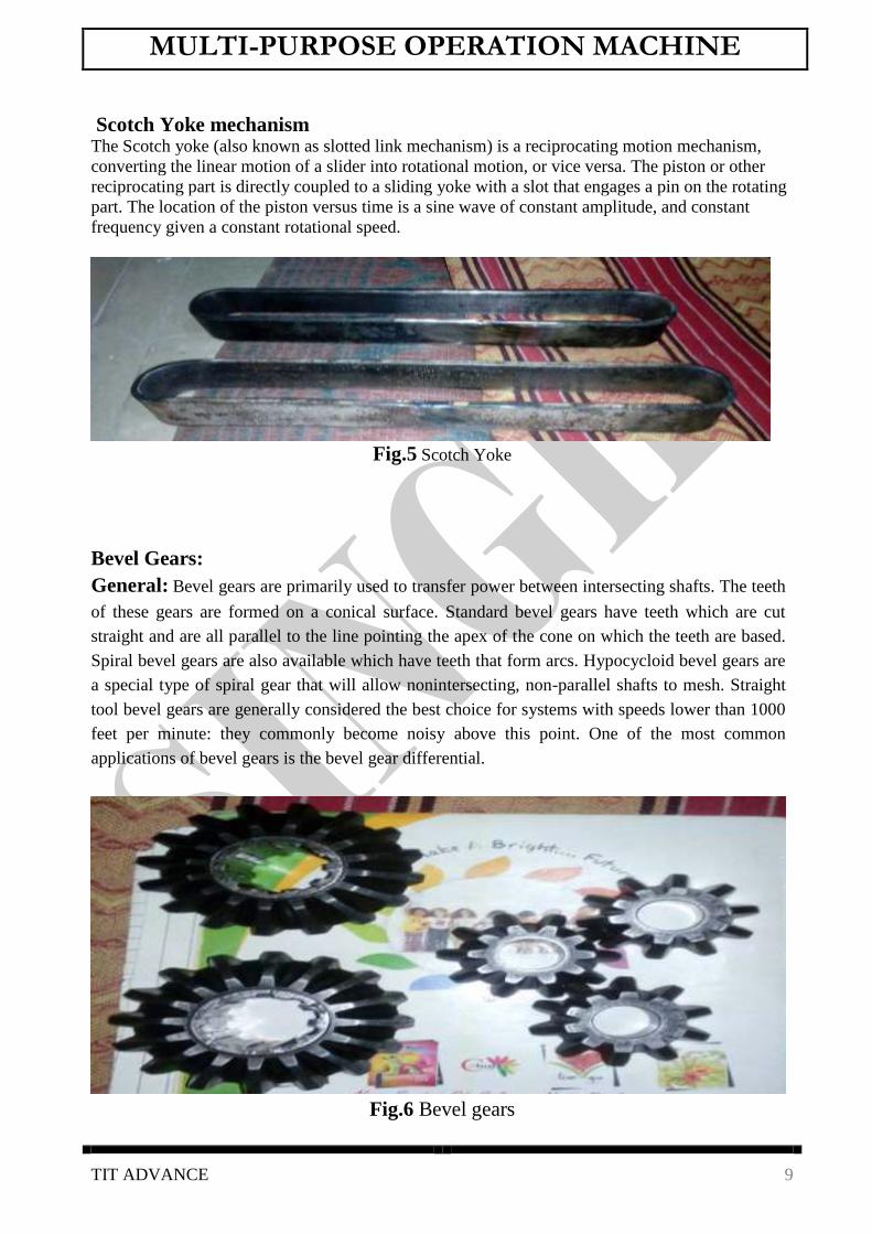
Scotch Yoke mechanism The Scotch yoke (also known as slotted link mechanism) is a reciprocating motion mechanism,
converting the linear motion of a slider into rotational motion, or vice versa. The piston or other
reciprocating part is directly coupled to a sliding yoke with a slot that engages a pin on the rotating
part. The location of the piston versus time is a sine wave of constant amplitude, and constant
frequency given a constant rotational speed.
Fig.5 Scotch Yoke
Bevel Gears: General: Bevel gears are primarily used to transfer power between intersecting shafts. The teeth
of these gears are formed on a conical surface. Standard bevel gears have teeth which are cut
straight and are all parallel to the line pointing the apex of the cone on which the teeth are based.
Spiral bevel gears are also available which have teeth that form arcs. Hypocycloid bevel gears are
a special type of spiral gear that will allow nonintersecting, non-parallel shafts to mesh. Straight
tool bevel gears are generally considered the best choice for systems with speeds lower than 1000
feet per minute: they commonly become noisy above this point. One of the most common
applications of bevel gears is the bevel gear differential.
Fig.6 Bevel gears
MULTI-PURPOSE OPERATION MACHINE
TIT ADVANCE 10
Limitations:
Limited availability cannot be used for parallel shafts, can become noisy at high speeds.
Advantages:
Excellent choice for intersecting shaft systems.
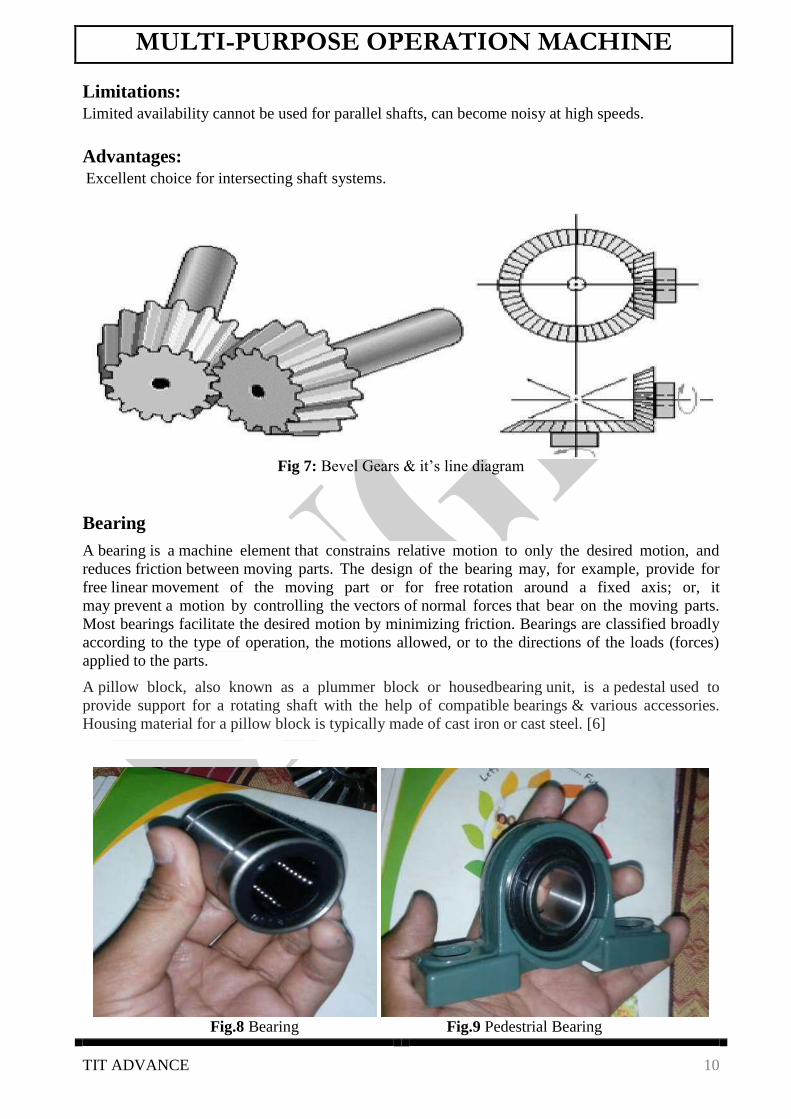
Fig 7: Bevel Gears & it‟s line diagram
Bearing
A bearing is a machine element that constrains relative motion to only the desired motion, and
reduces friction between moving parts. The design of the bearing may, for example, provide for
free linear movement of the moving part or for free rotation around a fixed axis; or, it
may prevent a motion by controlling the vectors of normal forces that bear on the moving parts.
Most bearings facilitate the desired motion by minimizing friction. Bearings are classified broadly
according to the type of operation, the motions allowed, or to the directions of the loads (forces)
applied to the parts.
A pillow block, also known as a plummer block or housedbearing unit, is a pedestal used to
provide support for a rotating shaft with the help of compatible bearings & various accessories.
Housing material for a pillow block is typically made of cast iron or cast steel. [6]
Fig.8 Bearing Fig.9 Pedestrial Bearing

MULTI-PURPOSE OPERATION MACHINE
TIT ADVANCE 11
Motor
A pump is a device that moves fluids (liquids or gases), or sometimes slurries, by mechanical
action. Pumps can be classified into three major groups according to the method they use to move
the fluid: direct lift, displacement, and gravity pumps.
Mechanical pumps serve in a wide range of applications such as pumping water from
wells, aquarium filtering, pond filtering and aeration, in the car industry for water-cooling and fuel
injection, in the energy industry for pumping oil and natural gas or for operating cooling towers. In
the medical industry, pumps are used for biochemical processes in developing and manufacturing
medicine, and as artificial replacements for body parts, in particular the artificial heart and penile
prosthesis.[6]
Fig. 10: 1/5HP Motor (2800RPM)
Drilling chuck
A chuck is a specialized type of clamp. It is used to hold an object with radial symmetry, especially
a cylinder. In drills and mills it holds the rotating tool whereas in lathes it holds the rotating
workpiece. On a lathe the chuck is mounted on the spindle which rotates within the headstock. For
some purposes (such as drilling) an additional chuck may be mounted on the non-rotating tailstock.
We use 0.5mm diameter drill chuck. [6]
Fig.11: Drill chuck

MULTI-PURPOSE OPERATION MACHINE
TIT ADVANCE 12
Single Point Cutting Tool
In the context of machining, a cutting tool or cutter is any tool that is used to remove material from
the workpiece by means of shear deformation. Cutting may be accomplished by single-point or
multipoint tools. Single-point tools are used in turning, shaping, planing and similar operations, and
remove material by means of one cutting edge. Milling and drilling tools are often multipoint tools.
Grinding tools are also multipoint tools. Each grain of abrasive functions as a microscopic single-
point cutting edge (although of high negative rake angle), and shears a tiny chip. [6]
Fig.12: HSS Single Point Cutting Tool
Lock Nut A locknut, also known as a lock nut, locking nut, prevailing torque nut, stiff nut
[1] or elastic stop
nut, is a nut that resists loosening under vibrations and torque. Elastic stop nuts and prevailing
torque nuts are of the particular type where some portion of the nut deforms elastically to provide a
locking action. The first type used fiber instead of nylon and was invented in 1931.[6]
Fig.13 Lock Nut

MULTI-PURPOSE OPERATION MACHINE
TIT ADVANCE 13
V. Operation Performed by The Machine 1) Drilling 2) Cutting 3) Shaping
Drilling: Drilling machine can be defined as an instrument which is used to drill holes. Drilling machine
plays an important role in mechanical workshops. The purpose of this project work is to get hold of
complete information pertaining to drilling machines. A drilling machine comes in many shapes
and sizes, from small hand-held power drills to bench mounted and finally floor-mounted models.
Today the Industrial growth is purely depending up on latest machines; therefore, the subject of
drilling machines is extended too widely, because today wide varieties of drilling machines are
designed for various applications. The most advanced version-drilling machine is CNC (Computer
Numeric Control); it is used for drilling the PCB‟s (Printed).[6]
Cutting: A hacksaw is a fine-tooth hand saw with a blade held under tension in a frame, used for cutting
materials such as metal or plastics. Hand-held hacksaws consist of a metal arch with a handle,
usually a pistol grip, with pins for attaching a narrow disposable blade. A screw or other mechanism is used to put the thin blade under tension. The blade can be mounted
with the teeth facing toward or away from the handle, resulting in cutting action on either the push
or pull stroke. On the push stroke, the arch will flex slightly, decreasing the tension on the blade,
often resulting in an increased tendency of the blade to buckle and crack. Cutting on the pull stroke
increases the blade tension and will result in greater control of the cut and longer blade life.[6]
Shaping: The shaping machine is used to grind flat metal surfaces especially where a large amount of metal
has to be removed. Other machines such as milling machines are much more expensive and are
more suited to removing smaller amounts of metal, very accurately. A shaper is a type of machine
tool that uses linear relative motion between the work piece and a single-point cutting tool to
machine a linear tool path. Its cut is analogous to that of a lathe, except that it is (archetypal) linear
instead of helical. (Adding axes of motion can yield helical tool paths, as also done in helical
planning.) A shaper is analogous to a plane, but smaller, and with the cutter riding a ram that
moves above a stationary work piece, rather than the entire work piece moving beneath the cutter.
The ram is moved back and forth typically by a crank inside the column; hydraulically actuated
shapers also exist. [6]

MULTI-PURPOSE OPERATION MACHINE
TIT ADVANCE 14
VI. Brief Description About Bevel Gear and Drive
Mechanisms.
Gear:
A gear or cogwheel is a rotating machine part having cut teeth, or cogs, which mesh with another
toothed part in order to transmit torque, in most cases with teeth on the one gear being of identical
shape, and often also with that shape on the other gear. Two or more gears working in tandem are
called a transmission and can produce a mechanical advantage through a gear ratio and thus may
be considered a simple machine. Geared devices can change the speed, torque, and direction of a
power source. The most common situation is for a gear to mesh with another gear; however, a gear
can also mesh with a non-rotating toothed part, called a rack, thereby producing translation instead
of rotation.
Comparison with Drive Mechanisms: The definite velocity ratio which results from having teeth gives gears an advantage over other
drives (such as traction drives and V-belts) in precision machines such as watches that depend
upon an exact velocity ratio. In cases where driver and follower are proximal,
gears also have an advantage over other drives in the reduced number of parts required; the
downside is that gears are more expensive to manufacture and their lubrication requirements may
impose a higher operating cost. [6]
Spur Gears General: Spur gears are the most commonly used gear type. They are characterized by teeth
which are perpendicular to the face of the gear. Spur gears are by far the most commonly available,
and are generally the least expensive. [8]
Limitations:
Spur gears generally cannot be used when a direction change between the two shafts is required.
Advantages:
Spur gears are easy to find, inexpensive, and efficient.
Fig. 14: Spur Gear (front and isometric view)

MULTI-PURPOSE OPERATION MACHINE
TIT ADVANCE 15
Helical Gears: General: Helical gears are similar to the spur gear except that the teeth are at an angle to the
shaft, rather than parallel to it as in a spur gear. The resulting teeth are longer than the teeth on a
spur gear of equivalent pitch diameter. The longer teeth cause helical gears to have the following
differences from spur gears of the same size. [9]
Limitations:
Helical gears have the major disadvantage that they are expensive and much more difficult to find.
Helical gears are also slightly less efficient than a spur gear of the same size
Advantages:
Helical gears can be used on non-parallel and even perpendicular shafts, and can carry higher loads
than can spur gears.
Fig 15: Helical Gear (top view, side view & isometric view)
Bevel Gears: General: Bevel gears are primarily used to transfer power between intersecting shafts. The teeth
of these gears are formed on a conical surface. Standard bevel gears have teeth which are cut
straight and are all parallel to the line pointing the apex of the cone on which the teeth are based.
Spiral bevel gears are also available which have teeth that form arcs. Hypocycloid bevel gears are
a special type of spiral gear that will allow nonintersecting, non-parallel shafts to mesh. Straight
tool bevel gears are generally considered the best choice for systems with speeds lower than 1000
feet per minute: they commonly become noisy above this point. One of the most common
applications of bevel gears is the bevel gear differential. [10]
Limitations:
Limited availability cannot be used for parallel shafts, can become noisy at high speeds.

MULTI-PURPOSE OPERATION MACHINE
TIT ADVANCE 16
Advantages:
Excellent choice for intersecting shaft systems.
Fig 16: Bevel Gears & it‟s line diagram
Worm Gears General: Worm gears are special gears that resemble screws, and can be used to drive spur gears
or helical gears. Worm gears, like helical gears, allow two non-intersecting 'skew' shafts to mesh.
Normally, the two shafts are at right angles to each other.
A worm gear is equivalent to a V-type screw thread. Another way of looking at a worm gear is that
it is a helical gear with a very high helix angle. Worm gears are normally used when a high gear
ratio is desired, or again when the shafts are perpendicular to each other. One very important
feature of worm gear meshes that is often of use is their irreversibility: when a worm gear is turned,
the meshing spur gear will turn, but turning the spur gear will not turn the worm gear. The resulting
mesh is 'self-locking', and is useful in ratcheting mechanisms. [11]
Fig 17: Worm Gear
Limitations:
Low efficiency. The worm drives the drive gear primarily with slipping motion, thus there are high
friction losses.

MULTI-PURPOSE OPERATION MACHINE
TIT ADVANCE 17
Advantages:
Will tolerate large loads and high speed ratios. Meshes are self-locking
(which can be either an advantage or a disadvantage).
Racks (straight gears) General: Racks are straight gears that are used to convert rotational motion to translational
motion by means of a gear mesh. (They are in theory a gear with an infinite pitch diameter). In
theory, the torque and angular velocity of the pinion gear are related to the Force and the velocity
of the rack by the radius of the pinion gear, as is shown below: Perhaps the most well-known
application of a rack is the rack and pinion steering system used on many cars in the past. [12]
Limitations:
Limited usefulness, difficult to find.
Advantages:
The only gearing component that converts rotational motion to translational motion. Efficiently
transmits power. Generally, offers better precision than other conversion method.
VII. Maintenance and Lubrication. Many bearings require periodic maintenance to prevent premature failure, although some such as
fluid or magnetic bearings may require little maintenance. Most bearings in high cycle operations
need periodic lubrication and cleaning, and may require adjustment to minimize the effects of
wear. Bearing life is often much better when the bearing is kept clean and well-lubricated.
However, many applications make good maintenance difficult. For example, bearings in the
conveyor of a rock crusher are exposed continually to hard abrasive particles. Cleaning is of little
use because cleaning is expensive, yet the bearing is contaminated again as soon as the conveyor
resumes operation. Thus, a good maintenance program might lubricate the bearings frequently but
never clean them.
Packing: Some bearings use thick grease for lubrication, which is pushed into the gaps between the bearing
surfaces, also known as packing. The grease is held in place by a plastic, leather, or rubber gasket
(also called a gland) that covers the inside and outside edges of the bearing race to keep the grease
from escaping. Bearings may also be packed with other materials. Historically, the wheels on
railroad cars used sleeve bearings packed with waste or loose scraps cotton or wool fiber soaked in
oil, then later used solid pads of cotton.

MULTI-PURPOSE OPERATION MACHINE
TIT ADVANCE 18
VIII. Brief Description About Bevel Gears.
Bevel gears are used to transmit power between two non-parallel shafts. The shafts may be
intersecting or non-intersecting. Bevel gears can be described as conical gears as they are cut on
conical blanks (tapered). They are not interchangeable and always designed in pairs. The
commonly used bevel gears are: straight, spiral and hypoid based on the geometry as given below:
Straight Bevel Gears: The straight bevel gears are the simplest types of bevel gears. They are the important gears to
transmit power between intersecting shafts. Straight bevel gears are shown in Figure below. The
teeth are cut straight, have a taper, and if extended inward, would intersect each other on the axis of
shaft. The meshing gears have line contact. Hence, they are not smooth in operation; generate more
vibrations and noise at high-speed. They produce thrust load on shaft bearings. Straight bevel gears
are used for speed ratio 1:1. Their precision is as good as parallel helical gears, but higher than
crossed helical gears, spiral bevel gears, hypoid bevel gears and worm gears. [13]
Fig 18: Straight level Gears Mounted on shafts Fig 19: Left-on loom; Right-on Carding Machine.

MULTI-PURPOSE OPERATION MACHINE
TIT ADVANCE 19
Fig 20: Thrust load on Bevel gears
Fig.21: Gear Terminology
Spiral Bevel Gears: These gears are mounted on shaft whose axes are intersecting. The pitch surface is conical as
shown in Figure below. Spiral bevel gears have curved oblique teeth (spiral), which allow contact
to develop gradually and smoothly. They have more contact length and area and less power
transmission efficiency compared to straight bevel gears. They are useful for high-speed
applications and others requiring less noise and vibration. They are difficult to design and costly to
manufacture, as they require specialized and sophisticated machinery for their manufacture. They
produce more thrust load on shaft bearings than straight bevel gears. [13]
Fig 22: Spiral bevel gears

MULTI-PURPOSE OPERATION MACHINE
TIT ADVANCE 20
Their advantages compared with straight bevel gears at high speeds are: (a) smoothness and
quietness of operation; (b) strength; and (c) durability due to the followings:
Longer contact length and larger contact ratio compared to straight bevel gears of same
size.
Teeth engage gradually, the contact beginning at one end and gradually working over other
end; whereas in the straight bevel gear the contact takes place along the entire face of the
tooth at the same instant.
Hypoid Bevel Gears: Hypoid bevel gears are used to connect shafts whose axes do not intersect. They are very similar
to spiral gears. However, their pitch surfaces are hyperboloids rather than cones. As a result, their
pitch axes do not intersect. They permit certain amount of sliding action along the direction of
tooth element, which requires good lubrication. Their power transmission efficiency is poor
compared to other straight and spiral bevel gears. In general, hypoid gears are most desirable for
those applications requiring large speed reduction ratios, nonintersecting shafts, and also great
smoothness and quietness of operation. [14]
Fig 23: Hypoid bevel gears
Miter and Angular Bevel Gears: In majority of bevel gear drives, the shafts of the meshing gears are 90º to each other. If the angles
between the shafts are 90°, and the two gears of a pair are having the same number of teeth, then it
is called as “Miter Gear”. A pair of spiral miter gears is shown in Figure. In some bevel-gear
drives, the angles between the shafts may not be 90°, but either more or less than 90°. These gears
are called „Angular bevel gears‟. A pair of angular bevel gears is shown in Figure below.[6]
Fig 24: Spiral miter gears Fig 25: Angular bevel gears

MULTI-PURPOSE OPERATION MACHINE
TIT ADVANCE 21
Applications of Bevel Gears: Straight bevel gears are used primarily for low speed application with pitch line velocities up to
300 m/min. They are widely used in textile machines. Few of applications are listed below:
drive to bobbin rail on roving machine
drive between the doffer and feed roller on low speed carding machines
drive from calendar roller to coiler rollers, top coiler to bottom coiler plates in card, comber
and drawing machine
drive between calendar roll and lap stop mechanism-lever in lap former of conventional
blow room. [6]
IX. Fabrication of The Machine.
There are few types of fabrication methods that are done on the machine. They are: Arc cutting.
Drilling.
Grinding.
Turning.
Further Operation: Cleaning. Assembling.
Further Operations: Cleaning: It is the operation to clean the all machined parts without burrs, dust and chip formals. By
meaning the parts they are brightened and good looking.
Machining Operations: In this paper, it is used to cut the raw material such as plates, rod. This is done by arc cutting
machine.
Drilling: Drilling is used to produce holes in objects. In this project, the square type pipe required the holes
for making rake assembly. These holes are done by vertical type drilling machine.
Fine Grinding: It is nothing but a grinding process, which is done as smooth with fine grains. It is done by
convention grinding machine.
Turning: It is used in this project to make the groove on the both sides of top cover plate. This is done by
conventional lathe.

MULTI-PURPOSE OPERATION MACHINE
TIT ADVANCE 22
X. Working of The Model. In the conceptual model of “Multi-Functional operating machine” we are giving supply to
the main shaft (refer fig.13), as we move along the axis of shaft we have mounted a pair of bevel
gears, through the pinion shaft we are giving drive to drill shaft through belt-pulley arrangement, we have installed the stepped pulley in the arrangement therefore we can have made the speed
variation. Now again as we move along the axis of main-shaft further we have again used the bevel
gear arrangement to give the drive to grinding center. As we can see that the scotch yoke mechanism is directly fabricated to the main shaft and
have same angular velocity as that of main-shaft. It is the operation, its deals with the assembling of various parts produced by above operations.
Fig.26: Over view
Fig.27: Turning process Fig.28: Group work

MULTI-PURPOSE OPERATION MACHINE
TIT ADVANCE 23
Fig.29: Welding process
Fig.30: Group work
MULTI-PURPOSE OPERATION MACHINE
TIT ADVANCE 24
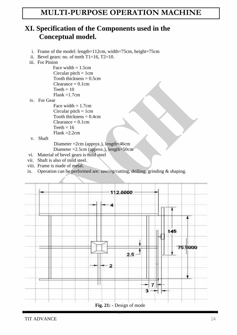
XI. Specification of the Components used in the
Conceptual model.
i. Frame of the model: length=112cm, width=75cm, height=75cm ii. Bevel gears: no. of teeth T1=16, T2=10.
iii. For Pinion Face width = 1.5cm
Circular pitch = 1cm Tooth thickness = 0.5cm
Clearance = 0.1cm
Teeth = 10 Flank =1.7cm
iv. For Gear
Face width = 1.7cm Circular pitch = 1cm
Tooth thickness = 0.4cm Clearance = 0.1cm
Teeth = 16 Flank =2.2cm
v. Shaft
Diameter =2cm (approx.), length=46cm
Diameter =2.5cm (approx.), length=50cm vi. Material of bevel gears is mild steel
vii. Shaft is also of mild steel. viii. Frame is made of metal.
ix. Operation can be performed are: sawing/cutting, drilling, grinding & shaping.
Fig. 21: - Design of mode

MULTI-PURPOSE OPERATION MACHINE
TIT ADVANCE 25
XII. RESULT
The scotch yoke mechanism is made and its advantage and disadvantage are discussed. Its
motion characteristics are studies. It is concluded that this mechanism is a good choice to convert rotating motion into reciprocating motion because of fewer moving parts and smoother operation.
The Scotch yoke is a mechanism for converting the linear motion of a slider into rotational motion
or vice-versa. The piston or other reciprocating part is directly coupled to a sliding yoke with a slot that engages a pin on the rotating part. The shape of the motion of the piston is a pure sine wave
over time given a constant rotational speed. The presented result can help to help the machining of work piece with expected tolerance.
The following major conclusion may be drawn from the study.
Multipurpose machine is derived from turning lathe which has been a well-established industrial process offering attractive capabilities for handling work piece of various length
to be use at micro level.
We have presented the development of multipurpose machine in various mode by which it can be actively adopted.
We have explained the various part and component of multipurpose machine using scotch yoke mechanism.

MULTI-PURPOSE OPERATION MACHINE
TIT ADVANCE 26
XIII. COSTING OF PROJECT
S.NO. PARTICULANS TOTAL
QUANTITY
COST
Rs/unit
TOTAL
COST
1. Motor 2800RPM 1 800 800
2 Bearing(Ball) 8 150 1200
3 Bearing (Roller) 4 120 480
4 Gear and Pinion 5 200 1000
5 Circular Disk 2 80 160
6 Shaft (M.S.) 4 90 360
7 Iron Angle(thickness-3mm) 10Kg 45 450
8 Drill Chuck 1 110 110
9 Drill Tool 1 40 40
10 Hacksaw Tool 2 60 120
11 Shaping Tool 2 250 500
12 Scotch and Yoke 2 250 500
13 Nut and Bolt 18 10 180
14 Holder (shaping) 2 90 180
15 Cable and Regulator 2 30 60
16 Transportation and other Expensive - 200 200
Rs6490

MULTI-PURPOSE OPERATION MACHINE
TIT ADVANCE 27
XIV. Conclusion The scotch yoke mechanism is made and its advantages and disadvantages are discussed. Its
motion characteristics are studied. It is concluded that this mechanism is a good choice to convert
rotating motion into reciprocating motion because of fewer moving parts and smoother operation.
It can be used in direct injection engines like diesel engines, hot air engines. In this project report
we provide an overview of the issues concerning different aspects of multipurpose machine using
scotch yoke mechanism. The paper focused on the principle of scotch yoke mechanism, type of
tooling and machining parameters and process performance measure, which include cutting speed,
depth of cut, material removal rate with different type of equipment which can be run
simultaneously and fabricate the work piece in multipurpose machine has been presented. The
presented results can help to plan the machining of work piece with expected tolerance. The
following major conclusions may be drawn from the study.
Multipurpose machine is derived from turning lathe which has been a well-established
industrial process offering attractive capabilities for handling work piece of various length
to be used at micro level.
We have presented the development of multipurpose machine in various modes by which it
can be actively adopted.
We have explained the various parts and components of multipurpose machine using scotch
yoke mechanism.
Different types of attachments and tools which can be implemented on multi-purpose
machine have been discussed.
MULTI-PURPOSE OPERATION MACHINE
TIT ADVANCE 28
XIV. Scope for Further Work
In this research, an integrated manufacturing application framework to link design stage to the
other stages in the manufacturing systems has been developed. An IPPPIS (Integrated Payroll and
Personnel Information System) has been developed to have a computer-based method for the
concurrent design of the part design, the tool design and the process design. Some directions for
further work are given below. Only the limited aspects of fixture issues were considered here.
However, fixture planning and fixture design is indispensable in setup planning which requires
more attention. Multi-spindle machine tools are widely used in mass production. They can execute
multiple processes at the same time, which can greatly increase productivity and reduce cycle time.
The machine tool capability model can be extended to multiple spindle machine tools in future
studies. In the part coding area, coding was restricted to 19-digit code in the design and process area. This
is to reduce the time for coding and overall prototype model development. This can be further
extended to more number of digits to enhance the accuracy of the retrieval. Some of the attributes
such as tolerance, tools, fixtures, etc., can be elaborated further in this context, according to the
requirement of the industry on which it is to apply.
In this research domain, knowledge in the setup planning and fixture design area is restricted with
more focus being given on process and design. This can be further elaborated with details of
fixtures design and setup planning depending upon the type of machine tools that are being used,
which can be linked with the framework.
Future research work can be planned for the improvement of the proposed framework, for creation
of a model for evaluation of productivity improvements, in order to quantify time and cost
reduction. Enhancement of the model through a workflow perspective, using the object-oriented
approach used here, will help extending the use of the model for the entire production system.

MULTI-PURPOSE OPERATION MACHINE
TIT ADVANCE 29
References
[1]. Heinrich Arnold the recent history of the machine tool industry and the effects of
technological change “University of Munich,
Institute for Innovation Research and Technology Management, November 2001. [2]. Dr. Toshimichi Moriwaki “Trends in Recent Machine Tool Technologies”
Professor Department of Mechanical Engineering Kobe University, NTN Technical Review
No.74(2006). [3]. T. Moriwaki “Multi-functional machine tool”, Department of Industrial and Systems
Engineering, Setsunan University, Neyagawa, Japan CIRP Annals - Manufacturing Technology DOI: 10.1016/j.cirp.2008.09.004 .
[4]. Frankfurt am Main “Multi-purpose machines ensure enhanced “, 1 January 11.
[5]. “Selecting and Planning the Process of Manufacture: Dr.Pulak M.Pandey. http://paniit.iitd.ac.in/~pmpandey
[6]. “Scotch Yoke Mechanisam ” from Wikipedia by google
“https://en.wikipedia.org/wiki/scotchyokemechanisam”
[7]. “Drilling” from Wikipedia by google “https://en.wikipedia.org/wiki/Drilling(engineering)”
[8]. “Spur Gear” from S.S.RATAN book, chapter 10 & page no.372
[9]. “Helical Gear” from S.S.RATAN book, chapter 10 & page no.372
[10]. “Bevel Gear” from S.S.RATAN book, chapter 10 & page no.373
[11]. “Worm Gear” from S.S.RATAN book, chapter 10 & page no.412
[12]. “Racks” from S.S.RATAN book, chapter 10 & page no. 420
[13]. “Straight Bevel Gear” from Wikipedia by google
“https://en.wikipedia.org/wiki/straightbevelgear”
[14]. “Hypoid Bevel Gear” from Wikipedia by google
“https://en.wikipedia.org/wiki/hypoidbevelgear”
[15]. Fadooengineers.com.
[16]. www.Scribd.com.