introductory text laboratory of the future 1900
TRANSCRIPT

Introductory text
Elementa 2
Laboratory of the future 1900 How does electricity get to the wall outlet? Why do airplanes fly? How do waves propagate? How does a pneumatic tube work? How is heat generated from movement and movement from heat? How can human effort be measured?
You can find the answers to these questions here and in these experiments. The principles behind these answers were discovered in the 19th century, at the dawning of industrialization.
The experiments not only try to answer the question “How does it work?”, but also to provide historical context by pondering the question “Why, what, wherefore?“ They also look at industrial applications and usefulness in our daily lives – up to the present day.
Introductory text Electrical Engineering
As physicists and engineers explored electricity and its many useful properties, they created a whole new area of technology with a fascinating universality: electrical engineering. The new technology made it possible to send messages all over the world in a flash and to supply every form of energy imaginable: motion, heat, and light.
Even in the “Age of Electricity,” conventional sources of energy were relied upon. Electricity was produced far away from the consumer in hydroelectric or steam power plants, and was transported with little loss to the point of consumption.
Electricity changed the way that cities worked, and everyday lives at home and at work. The time of day and the seasons lost their importance: electricity to power heating, refrigeration or lighting was available everywhere and at any time.

A closer look
The Van de Graaff generator is like a conveyor belt that transports electrical charges. Where the positive and nega-tive charges accumulate depends on the distribution of the residual charges from the last time the generator was used. As soon as the generator starts up and charge separation begins, the initial polarization is increased.
The wide rubber belt rolls over two rollers. Friction at the upper roller charges the rubber belt. The charge is transpor-ted on the belt downward and dissipates via a metal comb to a ball bar.
On the opposite side of the belt – the side moving upward – electric induction creates a charge of the opposite polarity. This charge is transported upward to the sphere and flows onto the sphere.
The sphere collects a steadily increasing amount of charge. With the right design, it is possible to generate several milli-on volts.
This Van de Graaff generator can generate about 150,000 volts running idle. But the biggest current that it can pro-duce is minute: about 6 millionths of an ampere.
Hair-raising electricity!
Warning: This experiment is conducted by one of our TECHNOscouts. Please follow their directions!
Touch the big metal sphere.
As soon as the Van de Graaff generator starts running, you’ll feel a prickling of your skin and the hair on your head may start to stand up.
What's happening here?
Electrical charges can be generated by rubbing plastic. In this case, the rubber band is rubbed against the plastic roller that drives it, and so gets electrically charged: up to about 20,000 volts.
This electrical charge is transferred onto the large metal sphere. When you touch the metal sphere, the charges flow onto your insulated body and charge it up.
Because charges of the same type repel each other, light-weight objects, in particular your hair, move away from your body, so your hairs stands on end.
Although the voltage is very high, this experiment is comple-tely safe because only extremely small currents flow.
ElectricalEngineering
31
2
Van
de
Gra
aff
gen
erat
or

01.0
6.2
013
TEC
HN
OSE
UM
Van
de
Gra
aff
gen
erat
orWhy, what, wherefore?
The Van de Graaff generator is a development of the earlier electrostatic generators – the early elec-trifying machines used in the physics laboratories of the early 18th century to study electrostatic pheno-mena.
Electrostatic generators were also very popular with the court society. They were used as entertaining demonstrations: from the dancing paper snippets to the “electric kiss”.
The American physicist Robert Jemison Van de Graaff (1901 – 1967) developed an electricity ge-nerator in 1929 based on a rubber belt conveyor – the Van de Graaff generator. At the Massachusetts Institute of Technology in 1933, he designed a 10 meter high generator that could generate 7 million volts, as an energy source for a particle accelerator in nuclear research.
From 1937, Van de Graaff generators were also used in radiography and in cancer treatment. Other high voltage sources are now used for these purposes.
4
ElectricalEngineering

What's happening here?
The small compass needles are magnetic, so they line up with the stronger fields of the larger mag-nets. The north poles of the larger magnets attract the south poles of the compass needles and vice versa.
The transparent cylinder contains oil and fine iron filings. The filings align themselves with the field of the large magnets. Now you can observe a mag-netic field in 3D.
What kind of forces are at work here?Put the magnets on the array of small compass needles.
Or trying putting the rod-shaped magnets into the transparent cylinder – shake the cylinder well first!
A closer look
The field of the larger magnets magnetizes the iron filings, which now act like the compass needles.
Did you know that besides iron, there are only two other metals that react to magnets: nickel and cobalt?
21
3Mag
net
ic fi
eld
s
ElectricalEngineering

01.0
6.2
013
TEC
HN
OSE
UM
Mag
net
ic fi
eld
sWhy, what, wherefore?
A flow of electrical current creates a magnetic field (see the experiment “Magnetic coil”). Without these fields, electric motors and generators could not work. (See the experiments “Electric Motor” and “Motor Generator”.)
4
ElectricalEngineering

What's happening here?When an electrical current flows through a coil, it creates a magnetic field that is the same shape as the one formed by the large, rod-shaped magnets.
The small compass needles are permanent magnets; that is, they are inherently magnetic. Therefore they line up with the magnetic field of the coil. Their north poles are attracted by the south pole of the magnetic field of the coil and vice versa.
When the current stops, the coil immediately becomes non-magnetic and the needles arrange themselves randomly.
How can you switch a magnet on and off?When the green light on the button lights up, push the button briefly to make a current flow through the coil. Watch what happens to the small compass needles.
A closer lookEvery cable carrying a current is surrounded by a magnetic field. The magnetic field lines run in circles around the cable. The direction of the field lines always points to the magnetic south pole.
When you wind the cable into a coil, the circular fields rear-range to a larger longitudinal field that has the same shape and effect as the field of the rod-shaped magnet.
After a short time, the power shuts off again; the light on the button is now red. What happens to the compass needles?
21
3
Mag
net
ic c
oil
ElectricalEngeneering
ElectricalEngineering

01.0
6.2
013
TEC
HN
OSE
UM
Mag
net
ic c
oilWhy, what, wherefore?
Electromagnets that can be turned on and off are very useful:
• At the junk yard, they can lift up and drop car bodies.
• When pulsed at the right frequency, electromag- nets can cause other magnets to rotate. This is how electric motors work. Try it yourself in the experiment “Electric motor”.
• In a relay, electromagnets can operate a switch by attracting a piece of metal.
• In sync with the rhythm of music, electromag- nets can repel themselves from a permanent magnet. This is how a loudspeaker works.
Can you think of other everyday examples of electromagnets?
4
ElectricalEngeneering
ElectricalEngineering

What‘s happening here?
When a conductor is moved near a magnet, an electrical voltage is created inside the conductor.
The faster you move the conductor within the magnetic field, the higher the voltage and the larger the reading on the voltmeter.
When you coil the conductor into loops and move it as a coil over and around the magnet, the voltmeter shows an even higher reading.
Electricity from a Magnet?
Take the copper wire and run it along the side of the rod-shaped magnet in front of you. Look at the voltmeter as you do it.
A closer look
This process is called electromagnetic induction, which is the generation of an electrical potential in a conductor (wire) when it “cuts” through the magnetic field. This happens when the conductor is moved through a magnetic field.
The longer the wire and the faster it moves across the field lines, the higher the potential that is induced. This is why in electrical generators the wire is wound into coils and moved across the magnetic field as fast as possible.
21
3
Ind
uct
ion
ElectricalEngeneering
ElectricalEngineering

01.0
6.2
013
TEC
HN
OSE
UM
Ind
uct
ionWhy, what, wherefore?
In an effort to reverse the effect of an electromag-net, an Englishman named Michael Faraday disco-vered electromagnetic induction in 1831.
In 1866, Werner von Siemens improved upon this principle significantly, and was able to generate large amounts of electricity with his dynamo.
The principle of induction is used on a large scale in generators for generating electricity and for trans-formers. But microphones also use induction on a much smaller scale to convert sound waves into electrical oscillations.
4
ElectricalEngeneering
ElectricalEngineering

A closer look
This experiment shows how a synchronous motor works. When you turn the coils on and off in the right sequence, you create a rotating magnetic field. The magnet at the center rotates at the same frequency as the magnetic field.
Actual synchronous motors are driven by alterna-ting current. With a supply frequency of 50 hertz, a synchronous motor runs at 3000 revolutions per minute.
Why is the magnet turning?
Push the three green buttons one after the other. If you get the timing right, the magnet in the middle will rotate. It works even better with two or three people. Try to make the magnet spin really fast.
What's happening here?
For as long as you hold a button down, a current flows through the corresponding coil. This coil becomes magnetic.
The magnet in the middle spins because one of its two poles is attracted by the coil and its other pole is repelled.
You can learn why passing a current through a coil creates a magnetic field in the experiment “Magnetic coil.”
31
2
Elec
tric
mo
tor
ElectricalEngeneering
ElectricalEngineering

01.0
6.2
013
TEC
HN
OSE
UM
Elec
tric
mo
torWhy, what, wherefore?
Synchronous motors stop running if they are not actuated or if they are slowed down too much under a load. What is more, they always run at the same speed (revolutions per minute). However, they are still suitable for powering electric clocks, which require a constant drive speed under a constant load.
More common are three-phase asynchronous motors. They are built differently, in that the rotation speed is always below the frequency of the magnetic field. Increasing the load on an asynchronous motor reduces its speed, but its driving force is increased.
4
ElectricalEngeneering
ElectricalEngineering

A closer look
The meter in the middle indicates how much cur-rent flows between the generator and the motor. The current increases when you add a load to the motor, by slowing it down or turning it in the opposite direction.
The generator then has to generate extra current, and it becomes harder to turn the generator. This is why a load on the motor is directly transferred to the generator.
What kind of load transmission is this?
Turn one of the crank handles and watch what happens to the other.Try turning both crank handles at the same time, either in the same direction or in opposite direc-tions. Watch the meter needle in the middle.
What‘s happening here?
When you turn the crank handle, you power a generator through the gear box. You can see how fast it turns by looking at the black and white disk.
The current from the generator powers the motor on the other side.
The sides are interchangeable because a generator can be used as a motor and vice versa.
31
2
Mo
tor-
Gen
erat
or
ElectricalEngeneering
ElectricalEngineering

01.0
6.2
013
TEC
HN
OSE
UM
Mo
tor-
Gen
erat
orWhy, what, wherefore?
In this experiment, you experience on a small scale a major problem of energy supply: power plants must generate electricity the moment it is needed. A single power plant, however, cannot react quickly enough to the varying demands for electricity.
Power companies form large grids to minimize the problem. The companies can buy electricity from each other to even out fluctuations in demand.
Some power companies also use pumped storage stations. In times of low demand, electricity is used to pump water into a lake at a higher elevation. When electricity demand increases, the pumped water is allowed to run downhill through a turbine, to generate electricity.
4
ElectricalEngeneering
ElectricalEngineering

A closer look
This demonstration is simply a transformer, in which the stationary copper coil functions as the primary coil and the moveable aluminum ring functions as the secondary coil.
An alternating current flows through the copper coil, which, just as in the case of an electromagnet, creates a magnetic field that constantly reverses its polarity.
Because of the constantly changing polarity, an alternating voltage is induced in the aluminum ring, which causes an alternating current to flow. This current always flows in a direction opposite to the current in the coil. As a result, the current in the ring creates an alternating magnetic field that is always the reverse of the magnetic field of the coil.
The magnetic poles of the coil and the ring change 50 times per second, but are always opposite to each other. This is why the magnetic fields repel each other and the ring jumps up.
If you listen carefully, you can hear a humming noise, which is created by the constant reversal of polarity.
The aluminum ring is a secondary coil with only a single loop. This results in an extreme transformer ratio and an immense current. If the ring was fixed, it would melt imme-diately.
Jumping Ring!
When the green light comes on, push the green button.
What's happening here?
The aluminum ring lies on a coil of wire with an iron core. When you press the button, the ring flies up and falls back down.
31
2
Jum
pin
g R
ing
ElectricalEngeneering
ElectricalEngineering

01.0
6.2
013
TEC
HN
OSE
UM
Jum
pin
g R
ingWhy, what, wherefore?
The principle of induction playfully demonstrated in this experiment is used in real life, for example, in li-near motors. These motors are not used to produce a rotating motion, but to produce a linear motion, such as pushing a magnetic levitation train.
4
ElectricalEngeneering
ElectricalEngineering

What's happening here?Two coils wrapped around a loop-shaped iron core form a transformer. The fixed coil on the left is called the primary coil because it is directly connected to an alternating current source. The coil on the right, which is exchangeable, is called the secondary coil and is the source of a transformed alterna-ting current.
The current has a frequency of 50 hertz, which means it changes its polarity 100 times per second. The transformer vibrates mechanically in time with the frequency of the current and creates the characteristic humming sound.
Can you hear the hum?Lift the upper iron core using the green handle and insert one of the three tethered coils over the right iron core. Then, connect the right coil with the two red plugs, push the green start button, and swing the upper iron core down again. Now, watch the light bulb and the meters.
A closer lookThe primary coil produces a magnetic field, as described in the experiment “Magnetic coil.” This magnetic field changes polarity 100 times per second. The closed-loop iron core transfers the alternating magnetic field to the secondary coil, where it induces an alternating voltage (see experiment “In-duction”). The larger the number of turns in the secondary coil, the higher the induced voltage becomes.
On both sides of the transformer (primary and secondary si-des), the voltage (volts) und current (amperes) are displayed. The electric power is the product of these two quantities. Ideally, if the transformer worked with no energy losses, the electric power would be the same on both sides. The ratio of the voltages corresponds to the ratio of the number of turns of the coils.
21
3
Tran
sfo
rmer
ElectricalEngeneering
ElectricalEngineering

01.0
6.2
013
TEC
HN
OSE
UM
Tran
sfo
rmerWhy, what, wherefore?
The greatest advantage of alternating current is that it can be transformed from one voltage to another. In order to transport electricity over vast distances, utility companies use the highest voltages and the lowest currents possible. This dramatically reduces energy losses, as demonstrated in the experiment “Power Transmission Line.”
However, using low voltages can also be very use-ful. For halogen track lighting, which was particu-larly popular in the 1990’s, the voltage is transfor-med to a safe value of about 12 volts. You could touch the tracks without getting an electric shock. The current was correspondingly larger.
Low voltages and high currents are also needed for arc welding. The high current causes the metals to melt at the weld.
4
ElectricalEngeneering
ElectricalEngineering

A closer look
You can learn more about how an alternating current transformer is constructed, how it works, and how voltage and current are interrelated in the experiment “Transformer”.
To transport electricity over vast distances using power transmission lines, the voltage is stepped up on the power station side prior to transmission. On the consumer side, the voltage is stepped back down. This type of transmission can only be done with alternating current, because of the need to use transformers.
Why are transmission lines operated at high voltage?
Using the green buttons, you can turn on the corres-ponding light bulbs.
Watch the models of the power transmission lines and the brightness of the lamps as you press the buttons.
What's happening here?
The electrical power, which is needed by a consumer, is the product of voltage and current.
In this experiment, the transmission line without a transformer carries electricity with low voltage and high current. The high current heats up the wires and much of the energy is lost.
The transmission line with transformers carries elec-tricity with high voltage and low current. The wires don’t get as hot and less energy is lost. This is why power transmission lines are operated with high voltages.
31
2
Pow
er T
ran
smis
sio
n L
ines
ElectricalEngeneering
ElectricalEngineering

01.0
6.2
013
TEC
HN
OSE
UM
Pow
er T
ran
smis
sio
n L
inesWhy, what, wherefore?
The Internationale Elektrotechnische Ausstellung (International Fair for Electrical Engineering) in Frankfurt am Main in 1891 impressed the experts and the general public alike by demonstrating elec-tric power transmission. High-voltage rotary current (that is, three-phase alternating current, with a voltage of 15,000 volts) was transported with little loss from the hydroelectric power plant at Lauffen am Neckar over a distance of 175 km to Frankfurt. The question as to whether direct or alternating current should be used for the power networks was then decided in favor of alternating current.
The use of high voltages reduces the loss of energy in power transmission lines. This is why electricity grids use power transmission lines operating at up to 400,000 volts.
On the other hand, these power transmission lines have their disadvantages. Because of the high voltage, the wires need to be widely spaced so that sparks cannot jump between them. The great dis-tance between the wires means that the magnetic fields produced by the wires cannot cancel each other out (see experiment “Magnetic Coil”). As a result, strong alternating magnetic fields are created near power lines with an impact on humans and nature that is still highly contested.
4
ElectricalEngeneering
ElectricalEngineering

What's happening here?For the lamp to be lit, the circuit has to be complete. Only then can the current flow from one pole of the voltage source through the lamp to the other pole. But this only works if the current can also flow through the switch.
If you use an electrical insulator as a switch, the current cannot flow and the lamp doesn’t light up.
What conducts the current?In the left-hand circuit, you can use the switch to turn the lamp on and off.
A closer lookMaterials that can conduct electrical current contain freely movable charges. These are particles with an electrical charge that can move in the material. In metals, the particles are electrons. In salt solutions, positively charged ions move in addition to negati-vely charged ions.
The more freely the electrons can move about, the better a conductor the material is. Copper, for example, conducts electricity 7 times better than iron.
There is a gap in the right-hand circuit into which you can place rods made from various materials and test them as switches. Watch the lamp as you do it.
21
3
Co
nd
uct
ors
an
d In
sula
tors
ElectricalEngeneering
ElectricalEngineering

01.0
6.2
013
TEC
HN
OSE
UM
Co
nd
uct
ors
an
d In
sula
torsWhy, what, wherefore?
Technology finds uses for both conductors and insulators. Take a simple electrical cable as an example. Inside, a good conductor, such as copper, must be used. On the outside is a non-conductive material, an insulator, which makes sure that the current only flows inside the cable and does not flow through another conductor – such as the human body.
4
ElectricalEngeneering
ElectricalEngineering

A closer look
A simple circuit with a power source, a switch, and a lamp:
Two lamps on one power source – how can that be?
Try out the green rotary switches in both circuits. Keep an eye on the meters and on the brightness of the lamps.
What's happening here?
The blue elements are electricity sources. The meters display the voltage in volts (V) and the current in amperes (A).
If you think of electrical current as like water flowing in a pipe, the electrical voltage corresponds to the water pressure.
On the left side you have a parallel circuit: both lamps receive the same voltage. The currents th-rough both lamps add to give the total current provided by the power source.
On the right side you have a series circuit: the current, whose magnitude is displayed, flows through both lamps. The lamps share the entire voltage of the power source. This means that only half the voltage is applied to each lamp, which-results in less brightness than in the parallel circuit or in the simple circuit.
Parallel circuit with a power source, two switches, and two lamps to which the same voltage is applied:
In the parallel circuit, the same voltage is applied to both lamps and the same current flows through both lamps. That is why the individual lamps glow just as brightly as in a simple circuit.
Series connection with a power source, a switch and two lamps through which the same current flows:
In a series connection of two lamps, only half the voltage is applied to each lamp. That is why each lamp glows less brightly than in the parallel circuit or in the simple circuit.
31
2
Co
nnec
tio
ns
– in
ser
ies
and
par
alle
l
ElectricalEngeneering
ElectricalEngineering

01.0
6.2
013
TEC
HN
OSE
UM Co
nnec
tio
ns
– in
ser
ies
and
par
alle
lWhy, what, wherefore?
Several lamps in a parallel circuit are just as bright as a single lamp. But this circuit has even more advantages.
If one of the parallel lamps burns out, the other lamps continue to glow. In a series circuit, all the lamps go out because the circuit would be interrupted. It is also more difficult to figure out which lamp has burned out.
The voltage in the parallel circuit is the same for each lamp or any other electrical device. This is useful because most electrical appliances are designed for a certain voltage.
4
ElectricalEngeneering
ElectricalEngineering

A closer look
The skin on your hands always contains moisture and salt. When you touch the metal rods, the salt solution attacks the metal rods.
The metal rods are connected by your body, and a voltage (potential difference) is created between them.
The meter displays the voltage. How high the vol-tage is depends on the kind of metals - more preci-sely, on their position in the electrochemical series.
The greater the distance between the positions of the two metals in this series, the higher the voltage produced by holding the metal rods becomes.
When you put the six built-in metal rods in order of the electrochemical series, you get this line-up: stainless steel, copper, iron, brass, aluminum, and zinc. This is why the voltage is the highest between stainless steel and zinc.
Hand-made Electricity?
Insert the plugs from two different metal rods into the sockets. Now hold the two metal rods, one in each hand.
What's happening here?
You can read off the voltage from the meter.
Now try to figure out which two metals produce the highest voltage.
31
2
Han
d b
atte
ry
ElectricalEngeneering
ElectricalEngineering

01.0
6.2
013
TEC
HN
OSE
UM
Han
d b
atte
ryWhy, what, wherefore?
An Italian doctor, Luigi Galvani, discovered this effect in the 1780's when he touched a dissected frog's leg with two different metals and the frog's leg started to twitch.
Galvani had discovered what was later named in his honor: the galvanic element. It is a combination of two different metals that are connected through an electrolyte. A voltage is produced between the two metals.
Alessandro Volta improved upon Galvani's discovery in 1800 by connecting several galvanic elements in series to form a battery.
For years, it's been hard to imagine life without batteries: be it the zinc-carbon cell (Leclanché cell) in a flashlight, a nickel-cadmium battery in a mobile phone, or the lead-acid battery in a car. Newer developments include alkaline batteries and the nickel metal hydride battery.
4
ElectricalEngeneering
ElectricalEngineering

Introductory text Communication
New means of transport and communication accelerated the exchange of news. Electrical telegraph lines, initially installed for the operation of railways, spanned the entire globe by the end of the 19th century as a communication network for everyone.
Telegraphs send messages in the form of short and long signals called “dots” and “dashes”. Direct conversations only became possible after the turn of the 20th century thanks to the telephone. Physical messages were sent at this time in major cities such as London or Berlin by pneumatic tube conveyor systems.
A means of communication that fascinated the masses starting in the 20th century also had its roots in the 19th century: motion pictures. With simple equipment, people marvelled at the early moving pictures.
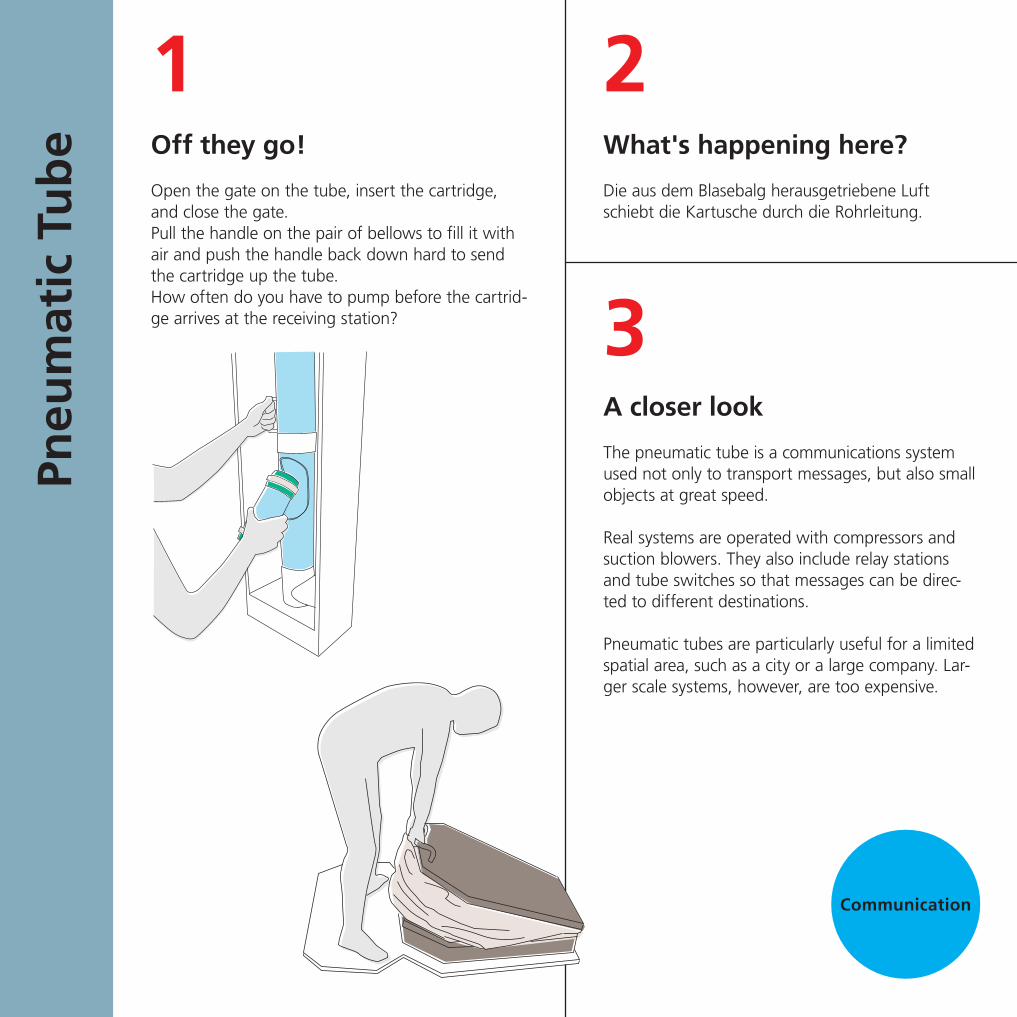
What's happening here?
Die aus dem Blasebalg herausgetriebene Luft schiebt die Kartusche durch die Rohrleitung.
Off they go!
Open the gate on the tube, insert the cartridge, and close the gate.Pull the handle on the pair of bellows to fill it with air and push the handle back down hard to send the cartridge up the tube.How often do you have to pump before the cartrid-ge arrives at the receiving station?
A closer look
The pneumatic tube is a communications system used not only to transport messages, but also small objects at great speed.
Real systems are operated with compressors and suction blowers. They also include relay stations and tube switches so that messages can be direc-ted to different destinations.
Pneumatic tubes are particularly useful for a limited spatial area, such as a city or a large company. Lar-ger scale systems, however, are too expensive.
21
3
Pneu
mat
ic T
ub
e
Communication

01.0
6.2
013
TEC
HN
OSE
UM
Pneu
mat
ic T
ub
eWhy, what, wherefore?
The first pneumatic tube systems were developed in London shortly after 1850. Between 1875 and 1945, they were widely used.
Pneumatic tubes have been pushed into the background by the competition of telephone, telex, and electronic media. But in the past few years pneumatic tubes have experienced a revival, transporting drugs and laboratory samples within hospitals, for example.
4
Communication

A closer look
You probably found that it's harder than you thought. But try to imagine – a trained operator can send or receive up to 300 letters per minute!
Do you know how to use Morse code?
Whether you do or not, give it a try! Find a partner and take your seats, one of you on each side of the table.
When you push the black button, a diode on your partner’s side lights up. Using long and short button-presses, you can form letters and words from the Morse alphabet shown on the plate.
You can note down what your partner “morses” back to you with chalk either in the Morse alphabet or immediately decoded into ordinary letters.
What's happening here?
As the sender, you encode (translate) our letter-based writing into a form that is easier to transmit as an electrical signal.
As the receiver, you must decode (translate back) these signals.
31
2
Mo
rse
Tab
le
Communication

01.0
6.2
013
TEC
HN
OSE
UM
Mo
rse
Tab
leWhy, what, wherefore?
When the network of railroads was being built in the 1830's, it became clear that for the safe opera-tion of this large-scale technology, it was necessary to communicate quickly across long distances. The emerging field of electrical engineering provided better options than the optical telegraphs, which had been used since ancient times.
An American named Samuel Morse developed a printing telegraph and introduced a code in the 1830's that would later be named in his honor. In 1865, this code became standardized.
Despite the rapid progress in communication tech-nology, Morse code is still in use and still being developed. For example, in the year 2004, a signal sequence for @, the “at“ sign in internet addresses, was introduced into Morse code.
4
Communication


A closer look
Every time a slit passes by the observer’s eye, the picture on the opposite side becomes visible for a brief moment.
The pictures show consecutive phases of the motion. The pictures are perceived in such a rapid sequence that the eye cannot distinguish the individual pictures from each other.
This process creates the illusion of a continuous uninterrupted movement, like in the movies.
When pictures learned to move
Turn the cylinder in the marked direction. Look through the slits at the pictures on the opposite side of the drum.
What's happening here?
The pictures combine to give the impression of continuous motion. The individual phases of the hammering process turn into a single working cycle.
31
2
Zoet
rop
e
Communication

01.0
6.2
013
TEC
HN
OSE
UM
Zoet
rop
eWhy, what, wherefore?
The 19th century saw the development of many devices that deceived the eye, making observers believe they were seeing continuous motion. Individual images on drums or plates were looked at using viewing equipment such as slits, mirrors or lighting with a flash.
One of the earliest devices of this kind was the zoetrope (Greek for “Wheel of Life”) of 1834. In the second half of the 19th century, film recordings and projection techniques were developed.
4
Communication

Introductory text Perception
We use our senses to perceive our surroundings and to understand them. But how reliable are our senses? Our senses get it wrong quite often when we try to estimate distances, heights, areas, weights or temperatures.
Sensory illusions cannot be completely avoided. They are based on the underlying processes of perception, which are not easily influenced by our conscious thought processes.
Still, we are able to objectify our perceptions by comparing, experimenting, and measuring. These are fundamental methods of the natural sciences and technology. We use measuring instruments in research, development and industrial production, that is, everywhere that our immediate senses are insufficient or our perception is not sensitive enough.

A closer look
From experience, we know that two objects com-bined are heavier than either object individually. And if two objects appear to be similar to each other, like our blocks, then they are usually made from the same material and have the same weight. Each block contributes half of the total weight.
Our experiences, which are quite reasonable and have served us well, influence our expectations when we lift the upper block. We expect it to be half as heavy as both blocks combined.
Since the upper block is made from a much heavier material than the lower block, we are surprised by the weight of the upper block, which appears to us to be even heavier than it actually is. We may even think that the upper block is heavier than both blocks combined.
Our mind tells us that this is impossible. But our senses are influenced by our experiences and expectations to such an extent that it’s hard to avoid the illusion.
How well can you estimate weights?
Stack the blocks and lift both of them with one hand.
Then, lift only the upper block. Are you surprised?
What's happening here?
The upper block seems to be surprisingly heavy. It may even feel heavier than both blocks combined. Why is that? Any idea?
31
2
”Mag
ic“
Blo
cks
Perception

01.0
6.2
013
TEC
HN
OSE
UM
”Mag
ic“
Blo
cksWhy, what, wherefore?
Sensory illusions are unavoidable. They have an im-mediate effect because the illusion is based on our learned experiences and on the underlying proces-ses of our perception, which can be influenced only slightly by conscious thought processes.
But we can objectify our sensory perceptions by comparing, experimenting, and measuring. These are the fundamental methods of the natural sciences and technology.
Measurement instruments, such as balances for measuring weights, help us whenever our imme-diate sensory impression deceives us or when our perception is not sensitive enough.
4
Perception
Which table is bigger? First, look at the tabletops and guess which is bigger. Then use the template to check. You will be surprised.
The template proves it: the tabletops are the same shape. Despite this proof, we will be fooled by this illusion again and again because it is based on important functions of our perception.
We overestimate the length of vertical distances, i.e., the edges of the table running from top to bottom. And we interpret perspective views spatially: the tables also extend backwards into space.

What's happening here?
The temperature indicator shows that the left button is at about 45 °C, the one on the right is at about 15 °C, and the one in the back is at room temperature.
But the room temperature button feels much colder to your left hand, which was placed on the warm button, than it does to your right hand, which was on the cold button.
Test your sense of temperature!
First, put one hand on each of the buttons at the front.Wait for about 30 seconds to let the different temperatures have an effect on you.Now, put both hands on the bigger button at the back.What do you feel?
A closer look
Our perception of temperature is subjective. How hot something feels depends on whether we come from warmer or colder surroundings.
This is demonstrated in this experiment: the hands are brought from opposite directions to the level of room temperature.
21
3
Feel
ing
tem
per
atu
res
Perception

01.0
6.2
013
TEC
HN
OSE
UM
Feel
ing
tem
per
atu
resWhy, what, wherefore?
Sensory illusions are unavoidable. They have an immediate effect because the illusion is based on our learned experiences and on the underlying processes of our perception, which can only be influenced by conscious thought processes to a limited extent.
But we can objectify our sensory perceptions by comparing, experimenting, and measuring.
These are the fundamental methods of the natural sciences and technology. Measurement instruments, like the thermometer used in our experiment for measuring temperatures, help us whenever the immediate sensory impression deceives us or when our perception is not sensitive enough.
4
Perception

A closer look
A drop of 20 cm corresponds to about 0.2 seconds of free fall time.
This is the time it takes an adult paying attention and in good shape to register the drop and react to it. Children usually take significantly longer to react.
Differences in the time it takes to catch a rod between both hands show that our hands are not trained in the same way and that their dexterity is different.
Test your reaction time!
Hang both rods in the magnetic holders at the top of the box.
The rods will be released after a random delay of a few seconds.
Try to catch the rods.
What's happening here?
Before you can catch the rods they will have fallen 20 cm or more.
Typically, one hand is faster than the other, and it is generally always the same hand.
31
2
Cat
chin
g R
od
s
Perception

01.0
6.2
013
TEC
HN
OSE
UM
Cat
chin
g R
od
sWhy, what, wherefore?
Reaction time is important if you’re working at a machine and in dangerous situations. This is why reaction times became the subject of testing toward the end of the 19th century.
The apparatus with the falling rods was developed by applied psychologists in the 1920s to test reaction times.
4
Perception

A closer look
Our indicating calipers, using the principle of leverage, indicate deviations of the order of 1 to 2 millimeters.
The calipers are enlarged tenfold compared to the originals da-ting from the year 1900.
The originals were accordingly smaller and could detect small deviations between a tenth and a hundredth of a millimeter.
Simple indicating calipers typically have a gear ratio of about 1:10 to 1:20, at most 1:50. Our model uses a ratio of about 1:15.
For double indicating calipers, the gear ratios multiply. One can easily reach 1:50, or even 1:100 or more(our calipers have a ratio of 1:60).
How can you measure a length that can hardly be seen?
Turn the aluminum cylinder with the serrated knob.Watch the changes in shape of the cylinder and the movement of the pointer.
What's happening here?
The back part of the cylinder is slightly off-center. This deviation from the cylinder form is marked in red.
In the simple indicating caliper, the deviation from the cylinder form moves the short end of the lever, causing a larger movement of the long end of the lever, which can be seen easily on the scale.
In the double indicating caliper, the movement acts on two coupled lever arms one behind the other, producing an amplified motion on the scale.
3
1
2Ind
icat
ing
cal
iper
s
Perception

01.0
6.2
013
TEC
HN
OSE
UM
Ind
icat
ing
cal
iper
sWhy, what, wherefore?
The need for geometrical accuracy in technology is increasing. Before 1800, differences of several millimeters to over one centimeter were often tolerated in machine parts.
As of 1850, it was necessary in mechanical engineering to work accurately to one tenth or even one hundredth of a millimeter; and around 1900 it became necessary to be accurate within one thousandth of a millimeter.
Such fine differences could no longer be detected by the naked eye or simple scales. Mechanical precision gauges were the tools that made it possible to detect such fine differences. Today's optical and optoelectronic devices can even measure much smaller differences.
Perception
4

Introductory text Aerodynamics
The first flying machines from the time before 1800 – hot air and gas balloons – were lighter than air. Barely maneuverable, they would drift in the wind. Powered airships from 1900 onwards were maneuverable but were unwieldy and slow.
Otto Lilienthal made the first flight with a craft that was heavier than air in 1891. With his glider, he imitated the flight of birds, which he had been studying for years. In 1903, the Wright brothers succeeded in performing the first powered flight with their biplane. Based on these early flying machines, and accelerated by world war and civil competition, the modern high performance airplane was developed by 1940.
A new branch of engineering made a major contribution to the development of the technology of flight: aerodynamics. It is used to study and optimize airflow and lifting forces on airfoil profiles.

A closer look
Smooth flow fields are called “laminar”, and swir-led ones are described as “turbulent”. Turbulent flow causes great resistance and large energy losses during the movement of the object. Laminar flow indicates the opposite: the profile of the object is streamlined or “aerodynamic”.
Flying requires streamlined airfoils such as the oran-ge one. But even for this airfoil, the flow has to stay close to the upper surface and must be laminar to produce the necessary low pressure for creating a pressure difference, which is required to create the lift needed to allow an object to fly.
Which profiles are aerodynamically efficient?
Use the magnet to pull various objects through the liquid.What kinds of turbulent swirls can you generate? Can you do it without turbulence?
What's happening here?
The liquid flows around the moving object, which pushes the liquid to the side. Behind the object, the liquid comes back together.
The flow field at the front of the object remains smooth, but turns into swirls at the rear, i.e., in the wake. The overall shape of the flow field depends on the form, the position, and the speed of the object.
31
2
Flo
w W
all
Aerodynamics

01.0
6.2
013
TEC
HN
OSE
UM
Flo
w W
allWhy, what, wherefore?
Finding streamlined forms is an important task in the development of vehicles, aircraft, and ships, but also for the design of piping systems for water or other liquids, such as oil.
To perform this task, the research fields of aerodynamics and hydrodynamics developed a multitude of mathe-matical and experimental methods, including the use of the enormous computing capacities of modern data processing installations.
4
Aerodynamics

A closer look
Smooth flow is called “laminar”, whereas swirling flow is described as “turbulent”.
To keep a heavy airplane in the air, a sufficient pressure difference between the top and bottom of the wing is needed.
The pressure difference is produced by the high pressure generated on the lower surface of the wing, where air is pushed downward, and by the low pressure produced on top of the wing. The low pressure is the greatest when the flow is mostly attached to the surface of the wing and remains largely laminar.
If the angle of attack is increased until the flow above the wing detaches completely, the airplane loses its lift and drops.
How does the flow change with the profile?
Push the green start button.
Vary the wind speed using the knob and the angle of attack of the profile using the handle.
Watch how the flow changes as you do this and how it creates smooth and swirled sections.
What's happening here?
Below the airfoil, the flow is always close to the wing surface. On the upper side, the flow is smooth at small angles of attack and low speeds. At larger ones, an area with swirls is created towards the back.
At an angle of about 15°, the flow completely detaches from the upper surface, and forms one large vortex in which the air flows back.
31
2
Stre
amlin
es
Aerodynamics

01.0
6.2
013
TEC
HN
OSE
UM
Stre
amlin
esWhy, what, wherefore?
Only when the flow field over an airfoil was made visible could engineers understand what a given airfoil geometry could accomplish.
For pilots, it became possible to interpret the behavior of an airplane at various velocities and attitudes of flight.
4
Aerodynamics

What's happening here?
At first, you feel the pressure of the air jet pushing the disk down.
But when the disk is very close to the plate, the disk is lifted up and floats freely.
What does the disk do in the flow of air?
Turn the blower on using the green button. Raise the disk slowly up to the plate with the air outlet.
A closer look
The effect is surprising – you'd expect the airflow to push down on the disk. Instead, the disk is sucked towards the plate.
Bernoulli’s principle is at work here. The principle sta-tes that a lower pressure exists in a fast-moving flow than in a slow-moving flow.
The airstream hits the center of the disk and is diver-ted in all directions toward the edge. As you raise the disk closer to the plate, the airflow increases in speed and creates low pressure that lifts the disk upward.
21
3
Glu
e-a
ir
Aerodynamics

01.0
6.2
013
TEC
HN
OSE
UM
Glu
e-a
irWhy, what, wherefore?
Daniel Bernoulli (1700 – 1782) was a member of a Swiss family that produced several mathematicians and physicists. They made important contributions to fluid mechanics and engineering mechanics in the 17th and 18th centuries.
Bernoulli’s principle describes mathematically the effect that makes it possible for objects heavier than air to fly: the pressure difference between the upper and lower surfaces of an airfoil in an airstream.
4
Aerodynamics

A closer look
The airfoil is positioned at an inclination to the airflow, that is with an “angle of attack” of about 5 – 10°.
The elevator influences this angle: if the angle is increased, the airplane climbs faster. As the angle is decreased, the airplane goes into level flight and then into descent.
The elevator does its job because of an effect that cannot be seen here, but which is explained by the “Streamline” experiment:
As the angle of attack changes, the flow field over the airfoil changes and, as a result, so does the pressure difference between top and bottom, which allows the airplane climb or descend.
But the airflow is also affected by the airplane’s speed. This is why it is possible to take off and land without using the elevator.
Are you ready for take-off?
Push the green start button. “Accelerate” by turning the green knob and steer with the joystick.Try several starts and landings. Watch how the airplane reacts to the wind velocity and the use of the joystick.
What's happening here?
The airplane is mounted on a balance that you can see below the table. Fans blow air toward the airpla-ne. At higher airspeeds, the airplane takes off and climbs as far as the balance allows. The rudder is used to change the direction of the airplane to the left or to the right.The elevator allows you to climb, transition into level flight, or descend.
31
2
Air
pla
ne
Aerodynamics

01.0
6.2
013
TEC
HN
OSE
UM
Air
pla
neWhy, what, wherefore?
Flying can be done with aircraft that are lighter than air, such as hot air or gas balloons. But it’s also possible to fly with aircraft that are heavier than air if they have a shape that the lifting forces of an airflow can act upon.
Albrecht Ludwig Berblinger conducted glider expe-riments in Ulm at the beginning of the 19th century – in the end without any convincing success. Otto Lilienthal made the most compelling breakt-hrough in Berlin in 1891. With his flying machines, he imitated the gliding flight of the birds that he had been studying for years.
Integrating power into a flying machine was achie-ved by the Wright brothers in the United States. In 1903, their biplane took off for the first powered flight. This was the beginning of a development that culminated in the modern high performance airplane.
An important contribution to the development of heavier than air flying machines was a new science that emerged with flight engineering: aerodyna-mics, which studies and optimizes flow fields and lift forces on airfoils.
4
Aerodynamics

Introductory text Thermodynamics
Thermodynamics is a branch of natural science concerned with heat and its relation to energy and mechanical work. Thermodynamics was fundamental to the improvement and development of heat engines, i.e., machines that transform heat into propulsive power. Heat engines became important motors of industrialization.
Steamboats and locomotives revolutionized the transportation system in the 19th century. In areas without enough water power, stationary steam engines were able to produce mechanical energy. A smaller and above all mobile heat engine, the internal combustion engine, provided for an even more widespread distribution of energy.
Even after the “Century of Steam” came to an end and the “Century of Electricity” dawned, steam power remained important – in the generation of electricity.

A closer look
When you compress air or another gas, you perform compression work. This work is converted into heat. Mechanical energy and heat, according to the first law of thermodynamics, are equivalent. In other words, both are forms of energy that can be converted back and forth, from one to the other.
When you compress the gas quickly enough or when the pump is well insulated, no heat can escape into the surroundings and the temperature of the compressed gas rises. This is called an adiabatic temperature rise.
What happens when air is compressed?
Pump hard several times and watch the temperature indicator.
What's happening here?
When you pump, you do the same thing as when inflating a bicycle tire: you compress air. When you inflate the tire, you notice that the pump warms up.
In this experiment, you can follow on the tempera-ture scale how the air warms up as you pump.
31
2Ad
iab
atic
Tem
per
atu
re R
ise
Thermodynamics

01.0
6.2
013
TEC
HN
OSE
UM
Ad
iab
atic
Tem
per
atu
re R
iseWhy, what, wherefore?
Thermodynamics is concerned with the relations-hip between pressure, temperature, and volume. It developed in the 19th century from the scientific study of steam engines. It explored the foundations of all kinds of heat engines, which are machines that convert heat into mechanical propulsive power.
The first law of thermodynamics is the law of conservation of energy. The law states that mechanical energy and heat energy are equivalent. The constant of proportionality between these two forms of energy, the so-called mechanical equivalent of heat, was proposed by Julius Robert Mayer in 1842.
4
Thermodynamics

A closer look
The model visualizes the kinetic theory of gases. This theory interprets heat as movement of gas particles.
The warmer the gas gets, the faster the particles move about. They hit the container walls harder, which can be measured in the form of an increase in pressure and temperature. In addition, the gas par-ticles take up more space (if the container walls can be moved) which we can measure as an increase in volume.
How do gas particles move?
Push the green start button and watch what happens.
Turn the black knob to the left and to the right, What changes?
What's happening here?
Imagine you had some gas in a glass cylinder and that you could enlarge it with a magnifying glass to a gigantic scale.
You would see roughly the same process that you see here with the jumping beads: gas particles flying about everywhere.
If you were to increase or decrease the tempera-ture, you would see the gas particles move about faster or more slowly and occupy more or less spa-ce – just like the beads in the glass cylinder when you turn the “temperature” knob.
31
2
Gas
kin
etic
s
Thermodynamics

01.0
6.2
013
TEC
HN
OSE
UM
Gas
kin
etic
sWhy, what, wherefore?
Thermodynamics is concerned with the relationship of pressure, temperature, and volume. Thermodynamics was developed in the 19th century from the scientific study of steam engines and studied the basic principles of all types of heat engines – machines that convert heat into propulsive power.
The first law of thermodynamics is the law of conservati-on of energy. This law states that mechanical energy and heat energy are equivalent. The proportionality constant between these two forms of energy, the so-called mechanical equivalent of heat, was proposed by Julius Robert Mayer in 1842.
The kinetic theory of gases was developed in the 1850's by August Karl Krönig and Rudolf Clausius. They interpreted heat as movement of particles and thereby traced the first law of thermodynamics back to the long-established principle of the conservation of mechanical energy.
4
Thermodynamics

A closer look
The rotational movement of the crank handle is transferred from the lower plate to the upper plate only by friction.
When you turn the crank fast enough, the centrifu-gal governor with its two flywheel masses lifts the upper plate high enough that the frictional forces are no longer enough to accelerate it any more.
The upper plate has reached its maximum rotational speed. It won’t go any faster even if you turn the crank handle faster.
You can follow the experiment by watching the two rev counters; the display in the small numbers shows revolutions per minute.
The upper counter shows how the maximum rotatio-nal speed is gradually reached but not exceeded. The lower counter shows how fast the lower plate spins, meaning how fast you are actually turning the crank handle.
Can you spin the upper plate as fast as you want?
Try it yourself. Start by turning the crank handle slowly and then increase the speed. What happens to the upper plate?
What's happening here?
You cannot spin the upper plate as fast as you want. The centrifugal governor limits the rotation speed.
31
2
Cen
trif
ug
al g
ove
rno
r
Thermodynamics

01.0
6.2
013
TEC
HN
OSE
UM
Cen
trif
ug
al g
ove
rno
rWhy, what, wherefore?
Centrifugal governors regulate speed of rotation. For example, if a machine is under varying load and runs faster or slower than it is supposed to, the centrifugal governor steps in and returns the machine automatically to the target speed.
In our experiment, it is more accurate to refer to a rev or speed limiter, instead of a centrifugal gover-nor, because the device only controls the maximum speed of the machine. Below this rotational speed, the device has no effect.
Centrifugal governors were the most important group of speed controllers in the era of industrializ-ation. They were used in steam engines, as well as in gramophones, which need a constant playback speed even though they were powered by a clock-work mechanism, whose force decreased during playback.
4
Thermodynamics
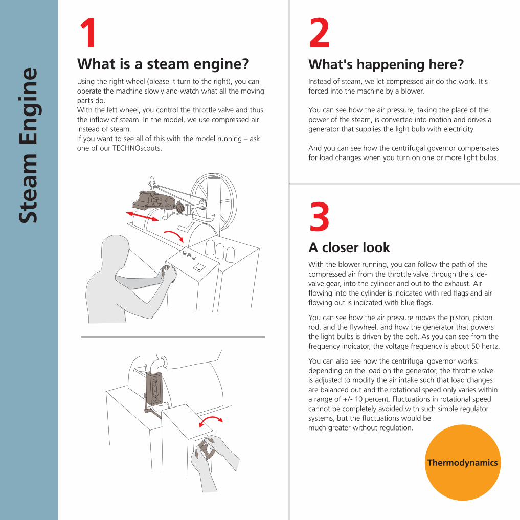
What's happening here?Instead of steam, we let compressed air do the work. It's forced into the machine by a blower.
You can see how the air pressure, taking the place of the power of the steam, is converted into motion and drives a generator that supplies the light bulb with electricity.
And you can see how the centrifugal governor compensates for load changes when you turn on one or more light bulbs.
What is a steam engine?Using the right wheel (please it turn to the right), you can operate the machine slowly and watch what all the moving parts do. With the left wheel, you control the throttle valve and thus the inflow of steam. In the model, we use compressed air instead of steam.If you want to see all of this with the model running – ask one of our TECHNOscouts.
A closer lookWith the blower running, you can follow the path of the compressed air from the throttle valve through the slide-valve gear, into the cylinder and out to the exhaust. Air flowing into the cylinder is indicated with red flags and air flowing out is indicated with blue flags.
You can see how the air pressure moves the piston, piston rod, and the flywheel, and how the generator that powers the light bulbs is driven by the belt. As you can see from the frequency indicator, the voltage frequency is about 50 hertz.
You can also see how the centrifugal governor works: depending on the load on the generator, the throttle valve is adjusted to modify the air intake such that load changes are balanced out and the rotational speed only varies within a range of +/- 10 percent. Fluctuations in rotational speed cannot be completely avoided with such simple regulator systems, but the fluctuations would be much greater without regulation.
21
3Stea
m E
ng
ine
Thermodynamics

01.0
6.2
013
TEC
HN
OSE
UM
Stea
m E
ng
ineWhy, what, wherefore?
Steam power was the most important source of power for the industrial age. In a eulogy for James Watt it was said that with a few pounds of coal, mankind will conquer the elements, and calms, headwinds, and storms will be laughed at.
James Watt (1736 – 1819) did not, in fact, invent the steam engine. Its invention can be traced back to the work of John Smeaton, Thomas Newcomen, Thomas Savery, Denis Papin, and Christiaan Huygens. As early as the middle of the 17th century, Otto von Guericke demonstrated the ability of atmospheric air pressure to perform work.
But Watt succeeded in improving upon Newco-men's atmospheric steam engine and produced a machine with much higher efficiency. Important improvements of the steam engine’s design and operation were, for example, the use of the positive steam pressure to drive the piston, and the conversion of the up and down movement of the piston into rotary motion.
Steam boats and locomotives revolutionized the transportation system in the 19th century. In areas without enough water power, stationary steam engines were able to generate mechanical energy.
Centrifugal governors regulate rotational speed. Despite their previous use in mills, the grand era of centrifugal governors began with the development of rotating steam engines in the late 18th century.
In 1788, James Watt introduced the centrifugal pendulum with balance weights to regulate the rotational speed of a steam engine for the first time. Subsequently, almost all rotating steam engines were equipped with a centrifugal governor well into the 20th century. Those regulators, which were more sophisticated than the model here, could automatically keep the rotational speed constant even under varying loads.
4
Thermodynamics

A closer look
In the Guericke crane in Elementa 1, the outside air pressure does work by pushing the piston into a cylinder that has been evacuated with a pump to produce a negative pressure. The piston movement can only be repeated after the intermediate container has been evacuated again.
In the case of this motor experiment, the high pressure injected air does work. It can push the piston in both directions (“double action”) by being rerouted. In principle, the pressure from steam or from hot combustion gases can also be used in this way.
In addition, the crank mechanism converts the back and forth movement of the piston into steady rotation – a movement that is technically very useful and which is used in most machines.
Here we have the basic form of a piston engine, which is used as the power unit in steam engines, water-column en-gines or combustion engines. It can work the other way: if you turn the flywheel, the piston can be used as a pump for water or air and other gases.
It is very important to control these machines precisely. You controlled the air flow by hand, but in real piston engines, it is controlled by automatic valves, such as in the experiment “Steam Engine.”
What turns the fly wheel?
Hold the black button down!
With your other hand, move the blower hose back and forth between the openings below the button.
Try to keep the flywheel rotating at a constant speed by skilfully switching between the openings!
What's happening here?
When you inject air into the cylinder on the left or the right of the piston, high pressure is produced on that side.
The high pressure acts on the piston and sets it moving. The piston pushes the wheel via the piston rod and connecting rod, and the wheel starts to turn.
You can make the wheel turn steadily if you move the blower hose to the other opening each time the piston changes direction.
31
2
The
firs
t m
oto
r
Thermodynamics

01.0
6.2
013
TEC
HN
OSE
UM
The
firs
t m
oto
rWhy, what, wherefore?
Otto von Guericke, Christiaan Huygens, and Denis Papin experimented in the 17th century with air pumps, gunpowder gases, and steam to create a vacuum in a cylinder and to let the atmospheric air pressure perform work on a piston.
Based on this principle, Thomas Newcomen built the first operational steam engine in England in 1710. It only produced a back-and-forth movement and was, therefore, limited to operating pumps in mines.
In 1760, James Watt made a crucial improvement to steam engines. Instead of atmospheric air, he used steam as a working medium and introduced “double action”, with the steam pressure driving the piston in both directions. In the 1780's, he also introduced machines that produced rotational mo-vements.
After Watt's patents expired, many successors beg-an, around 1800, to increase the pressure in order to improve the performance of steam engines. Steam engines became the most important motor behind industrialization in the 19th century. And the horizontal arrangement of the cylinders became the standard for factory engines.
After the internal combustion engine was invented around 1870, and used as a vehicle engine since the 1880's, piston engines were used widely in the 20th century.
4
Thermodynamics

A closer lookTwo factors are critical for running on the track: the diame-ters of the roller where it touches the rails, and the roller’s position relative to the track at the start.
For a cylinder, the diameters at the contact points are always the same, and the cylinder always rolls in a straight line per-pendicular to its position at the start, regardless of the route of the track.
Unless the double cone is placed straight and centered, its diameters at the contact points are always different in size. They form an imaginary cone. The rolling body moves around the tip of the imaginary cone on a circular path that leads away from the course of the track. In the process, the radius of the circular path changes constantly because the contact points (and hence the diameters) of the double cone move.
A double cone with small center diameter is unstable – the more off-course it is, the more it steers further off-course.
A double cone with a large center diameter is stable – the more off-course it is, the greater the tendency for it to re-turn to the center of the track.
The wheels mounted on an axle are also stable, but not because of the flanges. Instead, the running surfaces of the wheels are part of a double cone with large center diameter, i.e., the wheels are conically tapered outwards.
Which roller will stay on track safely?
Place the rollers straight and centered on the track and let them roll.
Now try it starting with the rollers off-center or not straight.
What's happening here?The cylinder stays on the track until it reaches the curve, but then it falls off the track.
The double cone with the small center diameter falls off the track even faster.
The double cone with the larger center diameter runs along the entire track even if it’s not perfectly straight to start off with.
The wheels on an axle stay on the track, but they slow down. They roll until the flange touches the rail and then stop.
Stay on Track
31
2Stay
on
Tra
ck
Thermodynamics

Wooden strap rails and wheels with flanges, around 1730(Troitzsch, Weber: Die Technik. Von den Anfängen bis zur Gegen-wart. [Technology. From the beginnings to the present] 1982)
Locomotive wheels with conical running surfaces and flange (Armengaud d. Ä., Carl Armengaud: Das Eisenbahnwesen [Railroad Industry]. 1841)
01.0
6.2
013
TEC
HN
OSE
UM
Stay
on
Tra
ckWhy, what, wherefore?
Railway vehicles use the effect of the stable rolling double cone – the vehicle’s wheels have conical running surfaces. The flanges are only an additional safety measure against derailing in curves and for the safe passage over railroad switch points.
A few flange-guided railway vehicles existed prior to 1800. With the spread of the railway after 1830, they gained an enormous importance.
It was probably discovered by experiment that conical running surfaces stabilize the running of the vehicle. Around 1840, this was basic knowledge and widespread railroad technology.
The advantage is lower wear. When travelling straight, the running surfaces alone keep the wheels on the track; the flanges rub against the rails only when travelling through a curve.
4
Thermodynamics

Introductory text Spinning Top
Rotating bodies attempt to maintain the orientation of their rotational axis. Any attempt to change the orientation is counteracted by “gyroscopic forces” that trigger a compensating motion.
In 1758, this effect was described numerically by Leonhard Euler. Before that, gunsmiths were already using the effect. They made firearms with rifled barrels to make the projectile spin, which stabilized the projectile in flight.
In mechanical engineering, it only became necessary to take into account gyroscopic forces once industrial machines had fast-spinning parts. Gyroscopic forces can also be used elsewhere: the gyroscopic compass was introduced around 1900 as a means of navigation that is independent of the magnetic field of the Earth. Also, the bicycle only works because of the stabilizing gyroscopic effects of its wheels.

What's happening here?
When you turn the rotational axis of the spinning wheel away from its initial position, you have to exert a force. The spinning wheel, together with the pole, platform and you, turns around the vertical axis of the platform.
In which direction will the spinning wheel turn?
Hold the wheel fork by gripping one of the handles and set the yellow wheel spinning quickly. Stand on the inner platform at the base of the pole, and hold onto both handles. Now, try to tilt the spinning wheel.
A closer look
Rotating bodies attempt to maintain the orientation of their rotational axis.
When trying to change the orientation, the rotating bodies react with “gyroscopic forces,” which cause a compensating motion.
21
3
Spin
nin
g W
hee
l
Spinning Top

01.0
6.2
013
TEC
HN
OSE
UM
Spin
nin
g W
hee
lWhy, what, wherefore?
Rapidly-spinning parts in industrial machines forced engineers to take into account gyroscopic forces.
At the same time, other opportunities to use this principle emerged: the gyroscopic compass was introduced around 1900 as a means of navigation that is independent of the magnetic field of the Earth.
And the bicycle, that experienced its first boom at around the same time, does not tip over thanks to the stabilizing gyroscopic effect of its wheels.
4
Spinning Top

A closer look
The suitcase contains a heavy, quickly-spinning wheel that resists any attempt to change the orientation of its rotational axis.
If you try to change the rotational axis from its current orientation, the spinning wheel in the suitcase reacts with a movement perpendicular to the axis.
In the Spinning Wheel exhibit nearby, you can see and experiment with the effect that here happens out of sight.
What is going on with the suitcase?
Lift the suitcase out of the holder. Move it around and turn it.
What's happening here?
When you move the suitcase in a straight line, nothing unusual happens. But when you try to turn the suitcase, you have to exert a great deal of effort.
The suitcase makes strange movements and twists upwards.
31
2
Wild
Su
itca
se
Spinning Top

01.0
6.2
013
TEC
HN
OSE
UM
Wild
Su
itca
seSpinning Top

Introductory text Oscillations
Oscillations and waves are periodic changes in state. In nature, they occur in a variety of forms, such as waves on water, vibrations of solid bodies, sound waves in the air, or as light.
In technology, vibrations are particularly useful: the oscillations of a pendulum, the balance wheel or quartz crystal in clocks and watches, the vibrations of metal or wood in musical instruments, or electromagnetic waves in telecommunications.
Oscillations, however, can also become a nuisance or even dangerous – as noise, as irritating vibrations in vehicles, or when a bridge starts to swing or vibrate so much that it is destroyed. That is why natural scientists and engineers study oscillations in great detail.

Genauer betrachtetWhat is light? Does it consist of oscillating waves or of fast-moving particles? Both interpretations go back to the 17th century. At the start of the 20th century, it was recognized that light, like all electromagnetic radiation, is in principle both a wave and a particle. Some phenomena, such as the photoelectric effect, can be explained better with the particle theory, while others, such as diffraction or polarization, are better understood by thinking of light as a wave.
ReflectionThe straight wave front, which is generated in our experi-ment by the straight wavemaker, corresponds to a bundle of parallel light beams. The barriers of different shapes act like mirrors reflecting light. The parabolic barrier focuses the waves into a focal point.
Doppler EffectAnother effect that occurs with propagating oscillations can be demonstrated graphically in the wave tank. When you move the single-point wavemaker, the circular waves are displaced off-center. In front of the point source, the waves move closer to each other and the frequency is increased. Behind the point source, the distance becomes greater and the frequency decreases.
This is the famous Doppler Effect, named after physicist Christian Doppler (1803 – 1853). This effect can occur with all kinds of oscillations. In our everyday lives, we most often perceive the effect acoustically, for example when a police car passes by with the siren on. We then hear the charac-teristic “iiiiiiiiiiiieeeeaaoouuuuuuu.” Ahead of the car, the sound waves are spaced more closely, and the siren appears to have a higher pitch. Behind the car, the sound waves are spread apart - the siren appears to have a lower pitch as the car drives away from us.
What patterns do waves make?
Ask a tutor for help.
Choose one of the three wave generators, push the start button, and adjust the closeness of the waves (the frequency) by turning the knob.
Put one of the barriers or a glass lens in the path of the waves.
Watch the tank and the white projection screen below to see how the waves move and cross each other.
What's happening here?
The straight wavemaker behind the glass wall generates wave fronts that are reflected at barriers and refracted at their edges and slits.
When they pass the convex lens (fatter in the middle), the waves converge. When they pass the concave lens (narrower in the middle) the waves spread out.
When the waves pass through a slit, concentric circular waves are generated. If there are two adjacent slits, the two wave patterns cross each other and make a characteristic pattern.
31
2
Wav
e Ta
nk
Oscillations

01.0
6.2
013
TEC
HN
OSE
UM
Wav
e Ta
nkWhy, what, wherefore?
Being able to watch water waves and how they are affected by obstacles allows us to learn important principles about the behavior of light waves and other electromagnetic waves, and sound waves too.
Those principles are useful whenever oscillations occur and spread, for example in mechanical engineering, telecommunications, optics, or acoustics. Sometimes we deliberately generate waves, as in the case of musical instruments, and sometimes we want to control how waves spread, for example when designing the acoustics of a concert hall.
But it can also be important to stop the formation and spreading of unwanted oscillations – for example, irritating noises or annoying vibrations. In particular, noise protec-tion in workplaces, acoustic shielding in residential areas, and noise reduction in buildings have gained importance in recent decades.
A conventional method of passive acoustic shielding is insulation. New methods for actively reducing noise make use of the effect that you observed with the overlapping concentric circular waves – when peaks and troughs cancel each other out, then there is silence. This is called “Active Noise Cancellation” (ANC).
The unwanted sound (noise) has an electroacoustically generated “anti-sound” of equal audio power added to it. The “anti-sound” is generated such that its peaks always coincide with the troughs of the noise sound waves, and vice versa. The noise and the “anti-sound” cancel each other out. Complete cancellation is rarely possible, but a significant noise reduction is achieved.
RefractionThe refraction of light with a lens can also be demonstrated in the wave tank. In the water above the lens, the waves are slowed down; that is, the waves move more slowly than in the surrounding deeper water. This is why the waves are bent towards the thicker parts of the lens. The result: the convex (fat in the middle) lens causes the waves to come together, and the concave lens causes them to diverge.
Light waves behave the same way – they move more slowly in a denser medium, such as glass, than in a vacuum. This is why convex lenses are used as converging lenses and concave lenses as diverging lenses.
Superposition (Interference)If the barriers have slits, the slits act like a series of point light sources, producing concentric circular waves. Those waves superpose to form a pattern of rough and smooth regions on the water. After a certain distance, the wave patterns recombine into a wave front.
The pattern can be studied in more detail with the barrier that has only two slits. You can see what happens when light passes through two closely-spaced slits – the diffraction of light in the so-called double slit experiment. A fan-shaped pattern of areas with strong waves and areas of complete calm is formed.
In the rough areas, peaks coincide with peaks and troughs coincide with troughs, so that very strong waves are created. In the case of light waves, you’d see bright light. In the calm areas, the peaks of the waves from one slit coincide with the troughs of the waves from the other slit: the waves cancel each other out and so the water is calm. In the case of light waves, this would mean darkness.
You can see the same effect with the double point wa-vemaker. You can adjust the distance between the two “light sources”, which in turn changes the fan-shaped wave pattern.
4
Oscillations

A closer look
If a spring is allowed to oscillate freely, it oscillates at its resonance frequency, which depends on the thickness of the wire, the diameter and length of the spring, and the elasticity of the material. The wave propagation speed also depends on these factors.
If the spring is actuated with a frequency near its resonance frequency, oscillations continuously build up in size. In extreme cases this can lead to the destruction of the spring.
Let it swing!
Use the rod to set both springs moving. Try changing the frequency, i.e., the time between two pushes.
Compare the shape and speed of the resulting oscillations.
What's happening here?
The spring on the left oscillates perpendicular to its axis. This is called a “transverse wave”. The spring on the right oscillates along its axis. This is called a “longitudinal wave”.
Both wave move at the same speed, but the closeness of the waves depends upon how rapidly you move the rod back and forth (the frequency).
For each spring, there is one frequency at which the oscillation is particularly strong. This is called the resonance frequency or eigenfrequency.
3
1
2
Big
Sp
rin
gs
Oscillations

01.0
6.2
013
TEC
HN
OSE
UM
Big
Sp
rin
gsWhy, what, wherefore?
All real mechanical systems have some elasticity and can oscillate. Machine parts, however, are usually very compact, which results in a high resonance frequency.
But since the end of the 19th century, the rotational speeds of machines have increased greatly, making it more likely that the resonance frequencies of some of the parts will be reached.
As a result, the analysis of oscillations has become increasingly important.
4
Oscillations