intruder alarm system engineering information · intruder alarm system engineering information the...
TRANSCRIPT

Intruder alarm system
Engineering Information
The above intruder systems are designed tocomply with the installation requirements ofBS 4737 1986/87.
This manual provides information on Installationdesign, panel fixing, wiring , power up andprogramming of the intruder panels.
Power 0 1 2 3
5 6 7 8
Chime Omit Reset
4
9
SetProg
PA
8EP 395 Optima G3 panelwith built-in keypad
8EP 396 Optima compact G3 panelwith built-in keypad
Attack
Tamper
Day
1 2 3 4 5 6 7 8
Power
Accenta�� ����
0 1 2 3
5 6 7 8
Chime Omit Reset
4
9
SetProg
PA
Attack
Tamper
Day
1 2 3 4 5 6 7 8
Power
Accenta�� ����
Power
0 1 2 3
5 6 7 8
Chime Omit Reset
4
9
SetProg
ZONE 1
ZONE 2
ZONE 3
ZONE 4
ZONE 5
ZONE 6
ZONE 7
ZONE 8
Tamper
Attack
Day Power
PA
Accenta
0 1 2 3
5 6 7 8
Chime Omit Reset
4
9
SetProg
ZONE 1
ZONE 2
ZONE 3
ZONE 4
ZONE 5
ZONE 6
ZONE 7
ZONE 8
Tamper
Attack
Day Power
PA
Accenta
8SP 401 Accenta G3 panelwith remote LED keypad
8SP 400 Accenta mini G3 panelwith remote LED keypad

Features
� 8 zones, all programmable for Security,Fire, 24H Fire, PTS or keyswitchapplications
� PA input
� Tamper input
� Outputs for Bell and Strobe
� 4 Access level Codes, User 1, User 2,Engineer and Duress, all programmable
� 3 fully selectable part set programs
� Chime on any zone
� 8 event memory
� Programmable timers including bell cut off
� Walk Test facilities
� Quick set feature
� Remote keypad with on board PA andilluminated keys standard for Accentapanels and Optional for Optima panels
� Option for connection of Lightingcontrollers
� Options to connect up to four remotekeypads / Lighting controllers
� NVM for protection of engineer programme
� 6 digital outputs for a wire-in digitalcommunicator, Red Care STU or dialler(Not applicable for Optima compact G3
panel)
� Service warning indicator, programmablebetween 100 and 800 set and unset events
� Battery capacity of up to :2.1Ah in Accenta/Optima G3 mini enclosure7Ah in Accenta/Optima G3 enclosure
� Optima G3 and Optima G3 mini are suppliedwith built in keypad
2 4PI175 issue 1_6/01
Engineering information Accenta/Optima G3 Intruder system
Featu
res
ContentsFeatures - - - - - - - - - - - - - - - - - - - 2
Installation Design - - - - - - - - - - - - - - 3
Fixing - - - - - - - - - - - - - - - - - - - - 3
Wiring the system - - - - - - - - - - - - - - 5
Tamper network - - - - - - - - - - - - - - - 5
Connect Remote Keypads / Lighting controllers 5
Security zones - - - - - - - - - - - - - - - - 5
Push to set zone - - - - - - - - - - - - - - - 6
Remote keyswitch zone - - - - - - - - - - - 6
Fire zone - - - - - - - - - - - - - - - - - - 6
PA circuit - - - - - - - - - - - - - - - - - - 6
Extension speaker - - - - - - - - - - - - - - 7
Bell Output (External sounder) - - - - - - - - 7
13V Supply output - - - - - - - - - - - - - - 8
Set - - - - - - - - - - - - - - - - - - - - - 8
Remote signalling Input and Outputs - - - - - 8Filtering of Intruder alarms - - - - - - - - - - - 9
Factory set condition - - - - - - - - - - - - - 10
First Power up - - - - - - - - - - - - - - - - 11
Mains Connection - - - - - - - - - - - - - - 11
Testing the system - - - - - - - - - - - - - - 12
Engineer program mode - - - - - - - - - - - 12To exit - - - - - - - - - - - - - - - - - - - - - 12
System indications - - - - - - - - - - - - - - 12
To enter Engineer program mode - - - - - - - 12
To Exit Engineer program mode - - - - - - - 12
To reset panel to Factory set conditions - - - - 12
Access Codes - - - - - - - - - - - - - - - - 13
Programs - - - - - - - - - - - - - - - - - - 14
Zone Function per Program- - - - - - - - - - 14
Exit Modes program - - - - - - - - - - - - - 14
Programs 1,2 and 3- - - - - - - - - - - - - - 15
Alarm and Walk tests - - - - - - - - - - - - 16
Communicator tests - - - - - - - - - - - - - 17
‘Flag A’ Options - - - - - - - - - - - - - - - 17
‘Flag B’ options - - - - - - - - - - - - - - - 18
Viewing the event log - - - - - - - - - - - - 18
Zone Type - - - - - - - - - - - - - - - - - - 19
Zone Attributes - - - - - - - - - - - - - - - 20
Bell and Service Timers - - - - - - - - - - - 21
Re-arm and Anticode reset code - - - - - - - 22
Lighting controller - - - - - - - - - - - - - - 23
Faults - - - - - - - - - - - - - - - - - - - - 24
Specification- - - - - - - - - - - - - - - - - 25
Servicing organisation Details - - - - - - - - 27
Parts - - - - - - - - - - - - - - - - - - - - 27
Quick Reference - - - - - - - - - - - - - - - 28
8z
RKP
4
PART
SET
MEM
8OUTPUT
6REMOTE
SET
5 0 9

Installation Design
The purchase of this alarm system represents amajor step forward in the protection of theproperty and its occupants. It is important to planthe installation before proceeding and the followthe procedures and advice contained in thismanual.
Plan the position of each part ofthe alarm system and the cableruns. Detectors should be sitedwith particular regard to thedegree of coverage required
and the function of each of the zones.
All of the system wiring isconnected directly to the panel.The Accenta panel may beconcealed inside a cupboard orloft space, but it must beinstalled within the protected
premises and in a position which is convenientfor a mains supply. The Optima panel may beinstalled near an entry/exit point.
The Remote keypads (RKPs)should be mounted in positionswhich allows ease of operationfor the system users, typicallywithin the entry/exit route close
to the final door and the master bedroom.
Additional internal sound
speakers are recommended,these will provide high volumealarm tones and low volumeentry/exit tones. Speakers should
be positioned to provide good sound distributionthroughout the building and so that the exit toneis audible outside the main entry / exit door.This will enable the system operator to checkthat the system is setting correctly.
Finally note that the total
current output of thiscontrol system (in alarmcondition) is 1Amp whensupported by a fully chargedbattery. Calculate the total
current consumption of every part of the systemincluding the panel, remote keypads,
bell/sounders, strobes and detectors to ensurethat this rating is not exceeded.
Depending on which areayou live, you may berequired, by law to notifythe Local Authority andPolice of the new securityalarm installation. The
local authority requirements may differ fromarea to area, therefore, it is advisable to contactlocal environmental officer to obtain full detailsof your area requirements.
Fixing
Caution: When positioning the controlpanel ensure that it is located in a dryplace away from damp areas.
The Accenta mini G3 enclosure is illustratedhere, however the procedures for the otherpanels are similar.
a. Remove the front cover(s) from thepanel.
Disconnect the transformer wires fromthe transformer marked AC terminalson the board. Carefully remove thePCB by gently pushing down theholding clips on the bottom edge of thePCB and withdraw it from the base.
4PI175 issue 1_6/01 3
Accenta/Optima G3 intruder system Engineering information
Insta
llati
on
Desig
n
ITOTAL
LA
�
�
�
Power
Accenta�� ����
0 1 2 3
5 6 7 8
Chime Omit Reset
4
9
SetProg
ZONE 1
ZONE 2
ZONE 3
ZONE 4
ZONE 5
ZONE 6
ZONE 7
ZONE 8
Tamper
Attack
Day Power
PA
Accenta

Note: When replacing the PCB align iton the round support pillars to thebottom and allow it to click down pastthe clips at the top of the case. Refit thetransformer wires into the terminal.
b. Fit the panel to the wall with suitablefixings. Ensure the wall surface is flat toprevent base distortion. There arecable entry holes provided in the rearof the base and around the outsideedges through the thinned out plasticsections which may be cut away asrequired.
c. The hole provided adjacent to themains transformer is a dedicated mainscable entry point.
Board
There are four fuses mounted on the circuitboard, all are 20mm quick blow.
F1 1.6A - to protect the +ve line of 12V battery
F2 1A - to protect the RKP 13V supply
F3 1A - to protect the Speaker 13V supply
F5 1A - to protect the Bell and Strobe supply
As supplied, wire links are fitted across the PAand Tamper terminals to represent a closedcircuit.
4 4PI175 issue 1_6/01
Engineering information Accenta/Optima G3 Intruder system
Fix
ing
J2
PA+
TAMP-
+13V 0V -STROBE
J6
+ - ACTAMP + T A
SCB
D BBELL
+ -
SET
1A 1A 1.6A
BE
LL
/ST
RO
BE
13
V/
SP
EA
KE
R
BA
TT
ER
Y
BATT
J4
F1F3F5
J5
0V
TAMP
+13V
COMMS
SOUND
VR1
VOLUME
21 43 65 87
1A
RKP FUSE
F2
ABORT
J3
+13VL/FAIL 0V FIRE PA INT SET CONF
Factory fitted links
0 1 2 3
5 6 7 8
CHIME OMIT RESET
4
9
SETPROG
Communicator is not fittedto Optima compact G3 panel
Keypad and LEDs (except Power LED) are notfitted to Accenta G3 and Accenta mini G3 panels
D1 D2 D3 D4 D5 D6 D7 D8 D9
D10
D22
D18
Mounting holes
Mounting holes
Cable entryholes
�
� �

Wiring the system
Caution: Always power-down the panelwhen wiring external circuits, to preventdamage to the panel electronics.
Systematically wire and test each circuits.:
� Zone, Tamper circuit and PA circuits
� Finish by wiring any additional extensionspeaker sounders, external bell/sounder,strobe and the 13V supply.
Tamper network
The Tamper circuit is used to protect all cablesand detectors in the system from unauthorisedaccess including the panel and RKP covers.
The zone and PA tampers should be series wiredand connected to the TAMP terminals.Terminals T & A are for the external bell /sounder tamper. The TAMP terminals at thebottom left of the PCB are for the RKP tampers.
Tamper alarms that occur in the Day modeoperate internal sounders only. Tamper alarms inSet cause a full alarm condition. Tamper isindicated on the control panel and RKPs by theTamper indicator.
Connect Remote Keypads /Lighting controllers
Note: Where an Accenta G3 or Accentamini G3 panel is being installed ensurethere is at least one remote keypad wiredto the panel before first power up.
A combination of up to four remote keypads andlighting controller can be connected to the panel.
Security zones
Note: The G3 range of panels are not
supplied with wire links for unusedzones. All unused zones must beprogrammed out by setting them todisabled using the Zone Type functionsee page 19.
It is recommended that no more than 10magnetic contacts are connected to the samezone.
4PI175 issue 1_6/01 5
Accenta/Optima G3 intruder system Engineering information
Wir
ing
the
syste
m
J5
0V
TAMP
+13V
COMMS
SOUND
1A
RKP FUSE
F2
Panel
BoardSO
UN
D
TA
MP
CO
MM
S
13
V
0V
Keypad
Board
CO
MM
S
12V
SO
UN
D
LD
R
Maximum of up to 4 Remote Keypad /OPTI-CAM Lighting Controllercombination allowed
Board
SO
UN
D
TA
MP
CO
MM
S
13
V
0V
Keypad
Board
GN
D
OPTI-CAM LightingController
(See also the instructions suppliedwith the OPTI CAM lighting controller)
If only one Remote keypadis being used then connect TAMP
back to the panel
J2
21 43 65 87
Panel
Alarm
+ -
PA+ -
TAMP +13V 0V
PIR
Unused zones mustbe programmed asUnused.
Board
PIR
DoorContact
DoorContact
Terminal blockis not supplied
Tamp

Push to set zone
Any zone can be wired and configured as a Pushto Set input. This can be a standard door bellpush located outside the premises After startingthe exit timer the building is vacated. As theswitch is then momentaraily closed, a chimetone is produced and the system Sets.Sometimes referred to as ‘Terminate Set’ thisfacility is mandatory for communicatingsystems installed to NACOSS guidelines
Remote keyswitch zone
Any zone can be wired and programmed as akeyswitch input and used with a remotekeyswitch or lock switch. For security reasons itis recommended that a tamper proof switch isused and that the switch wiring is not accessiblefrom outside the premises.
The keyswitch may be used to Set (opencontacts) or Unset (closed contacts)independently of RKPs. However in thissituation the keyswitch may have to ‘catch up’with the system. For example if the system is Setvia an RKP and Unset with the keyswitch, it
would have to be momentarily turned to its Setposition then returned to its Unset position.
The keyswitch will always Set program 1. It willalso Unset the system or switch off an alarmactivation. To Reset after an alarm and return toDay mode, the Reset key on the RKP will haveto be pressed.
Fire zone
Any zone may be programmed as a fire zone.This will automatically exclude the availabilityof the zone from programs and normal securityapplications.
There are two types of fire zone, Standard and24 hour type. The Standard fire zone detectsfires only when the system is Set, where as the24 hour fire zone detects fires all the time andwill operate whether the system is Set or Unset.A fire will cause a distinctive internal soundertone. The external sounders will pulse on and offat 2 second intervals and all RKP indicators willflash the affected zone.
PA circuit
Any quantity of normally closed type personalattack button may be wired in series and thenconnected to the PA circuit.
Operational in Day and Set, the PA circuit willcause a full alarm condition when activated. PAis indicated on the control panel or RKP asAttack.
6 4PI175 issue 1_6/01
Engineering information Accenta/Optima G3 Intruder system
Pu
sh
toset
zo
ne
J2
21 43 65 87
Panel
PA+ -
TAMP +13V 0V
Board
Keyswitch
Note: A keyswitch can beconnected to any zone.The zone must be programmedfor keyswitch application.
J2
21 43 65 87
Panel
PA+ -
TAMP +13V 0V
Board
Fire detector
Note: Fire detector withrelay base for outputto intruder system.
J2
21 43 65 87
Panel
PA+ -
TAMP +13V 0V
Board
Press to Set Switch
Note: The push to set switchcan be connected to any zone.The zone must be programmedfor PTS application.

PA buttons may be fitted near the front door, orin a bedroom.
Extension speaker
Extension speaker may be connected to theloudspeaker terminals to produce high volumealarm tones and low volume entry / exit faulttones.
Up to two 16 ohm extension speakers may alsobe wired across the speaker terminals. Mountedin convenient positions within the installationthe extension speakers will reproduce all of thealarm tones generated by the control panel.
A control marked VOLUME in the centre of thePCB may be used to adjust the low volumeentry/exit tones to suit environmental conditions.To adjust this control, partially lift up the topcover.
Bell Output (External sounder)
The bell is usually installed in a high positionfrom where the bell could be seen and heard.
Terminal T A D B are for connection to theexternal bell or sounder. These terminalsprovide a power/hold-off supply, soundertrigger and tamper circuit to protect the externalsounder housing.
The terminals are summarised as follows:
T - -Ve tamper return
A - -Ve supply (0V)
D - +Ve supply (12V)
B- -Ve Sounder trigger
For ease of installation, ADE sounders andmodules use the same markings.
Where a discrete bell sounder is used, it shouldbe connected to terminals D & B. Terminals T &
4PI175 issue 1_6/01 7
Accenta/Optima G3 intruder system Engineering information
Exte
nsio
nsp
eaker
J2
21 43 65 87
Panel
PA+ -
TAMP +13V 0V
Board
PanicButton
PanicButton
-STROBE
J6
+ T ASCB
D BBELL
+ -
SET
1A
BE
LL
/ST
RO
BE
F5
Panel
Board
1A
13
VS
PE
AK
ER
F3
16 � Extension Speaker
16 � Extension Speaker
VR1
VOLUME
-STROBE
J6
+ T ASCB
D BBELL
+ -
SET
1A
BE
LL
/ST
RO
BE
F5
Sonade
Panel
Board
+ - T E A D BSTROBE

A are then used for tamper protection for thesounder housing.
Where self contained / powered sounders areused, carefully follow the manufacturersinstructions, match each of the terminals tothose above.
13V Supply output
The 13V output is to power detectors whichrequire a voltage supply (PIR detectors etc). Thesupply is present at all times and may be used tosupply a total load of 350mA.
Set
The output , marked SET is used with latchingdetectors. The output becomes positive oncorrect Set of the system and is removed at thecommencement of entry time or entry of thevalid user code.
Remote signalling Input andOutputs
These outputs are not applicable to the
Optima compact G3 panel.
These terminals have been provided forconnection to remote signalling equipment suchas a digital communicator, Red Care STU orspeech dialler.
Note: The operating polarity of theCommunicator output terminals areprogrammable.
L/FAIL This is a telephone line fail input whichis held at approximately 6V by the panelcircuitry. The input is activated when pulled to0V by the telephone line fault output of thecommunicator. This is usually a voltage freerelay or open collector transistor.
When a telephone line fault occurs in the Daymode the panel provides an audible double beepevery 10 minutes. This indication isautomatically cleared when the fault is removed.
A telephone line fault which occurs while thesystem is Set will not cause an alarm conditionbut any bell delay which is programmed will becancelled and any intruder alarm which istriggered will operate instant sounders.
13V 0V These terminals provide a 13V supplyfor the communicator up to a total load of200mA. The output is protected by a 250mAthermal fuse. If this fuse operates it may be resetby removing the load and allowing a fewseconds for it to recover.
OUTPUT PORT By default these outputs areprogrammed as active low output. They are heldat 13V and fall to 0V when active, it can sourceor sink 10mA. The output polarity can beprogrammed.
8 4PI175 issue 1_6/01
Engineering information Accenta/Optima G3 Intruder system
13V
Su
pp
lyo
utp
ut
# Terminal blockis not supplied
-STROBE
J6
+ T ASCB
D BBELL
+ -
SET
1A
BE
LL/S
TR
OB
E
F5
Sonade
Panel
Board
+ - T E A D BSTROBE
#
Sonade
+ - T E A D BSTROBE

These outputs would normally be connecteddirectly to the input channels of wire in typecommunicators and STUs.
Alternatively each output can be used to drive a
relay(coil resistance > 1200 � ) connectedbetween the output terminal and the 13V supplyterminal. The relay will energise when theoutput port operates. It is recommended that aback EMF protection diode is used in parallelwith the relay coil.
FIRE The fire output operates when the firezone is triggered.
PA The PA output operates when a PA alarm istriggered or a duress code is used.
INT The intruder output is operated when anintruder condition is triggered whilst the systemis set.
SET The Set output operates whenever thesystem becomes set and is used to indicateopening and closing.
ABORT Operates when an intruder alarmcondition is switched off.
CONF The confirmed alarm output operateswhen 2 independent zones are activated duringthe same alarm condition.
Important Notes
a. Each output has been configured asactive low and will normally require theEPROM or NVM for the communicatoror STU to be programmed as activelow or positive removed. Howeverthere may be differences betweensome pieces of equipment and someAlarm Receiving Centres (ARCs).
b. Where the communicator is poweredfrom an external source, not the paneland the outputs are being used withoutrelays, the panel and external powersupply will require a commonednegative supply rail.
c. If the communicator is not fitted insidethe panel and abort is being used, careshould be taken to ensure that theabort connection cannot be damagedor severed as this could cause theARC to incorrectly filter an alarmsignal.
d. It is very important that communicatingsystems are fully tested and that allsignals are correctly received at theARC when the system is installed andserviced.
Filtering of Intruder alarmsA condition of most police Force Policies andunder the guidance of NACOSS NACP 14(Code of Practice for intruder Alarm SystemsSignalling to Alarm Receiving Centres) is thatall intruder alarm signals received by an AlarmReceiving Centre (ARC) must be filtered toestablish their validity before passing to thepolice.
The exact method of filtering should be decidedaccording to the regional Police Force Policyand ARC procedures.
In general, the panels offer the followingmethods which could be used to filter an alarm.
Set/Unset A Set or Unset signal which isreceived by the ARC at around the same time asan intruder signal can be used to filter the alarm.
Abort Output The abort output operateswhenever a user code is entered or a keyswitchis used to switch off an intruder alarm condition.When an abort signal is received by ARC at oraround the same time as an intruder signal, thealarm can be filtered.
Restore of the Intruder Output The intruderalarm output is restored to 12V whenever a usercode is entered or a keyswitch is used to switchoff an intruder alarm condition. Where anintruder alarm is shortly followed by a restore atthe ARC, this can be used to filter the alarm.
4PI175 issue 1_6/01 9
Accenta/Optima G3 intruder system Engineering information
Rem
ote
sig
nallin
gIn
pu
tan
dO
utp
uts

Factory set condition
User code 1 - - - - - - - - 0123
User code 2 - - - - - - - - Not programmed
Duress Code - - - - - - - - Not programmed
Engineer Code - - - - - - 9999
Bell Duration - - - - - - - 20 minutes
Bell Delay - - - - - - - - No delay
Program 1
Zone 1- - - - - - - - - Timed
Zone 2- - - - - - - - - Time Inhibited
Zones 3…8 - - - - - - Immediate
Exit time- - - - - - - - 30seconds
Entry - - - - - - - - - 30seconds
Exit mode - - - - - - - timed
Program 2
Zone1 - - - - - - - - - Timed
Zone 2- - - - - - - - - Time inhibited
Zone 3…8 - - - - - - - Immediate
Exit time- - - - - - - - 30seconds
Entry time - - - - - - - 30seconds
Exit mode - - - - - - - Disabled
Program 3
Zone 1- - - - - - - - - Timed
Zone 2- - - - - - - - - Time Inhibited
Zone3…8 - - - - - - - Immediate
Exit time- - - - - - - - 30seconds
Entry time - - - - - - - 30seconds
Exit mode - - - - - - - Disabled
Security Zones - - - - - - - Zones 1…8
Standard Fire zones - - - - None programmed
24 hour Fire zones - - - - - None programmed
Push to set zones - - - - - - None programmed
Keyswitch zones - - - - - - None programmed
Double Knock zones - - - - None programmed
Omit prevent zones- - - - - None programmed
Zone debounce period - - - 300mS ALL zones
Flag A
Silent PA - - - - - - - - - No
RKP PA Enable - - - - - - Yes
Engineer Reset- - - - - - - No
Anti Code Reset - - - - - - No
Door bell on push to set - - No
Single key setting - - - - - No
Strobe on setting - - - - - - No
External bell on Fire - - - - No
Flag B
Note: The entries marked # are notapplicable for Optima compact G3 panel.
#Communicator Outputactive high - - - - - - - - - - No (active low)
#Line Failactive high - - - - - - - - - - No (active low)
User Reset PA - - - - - - - - No
User Reset Fire - - - - - - - - No
#Program 1 to report - - - - - Yes
#Program 2 to report - - - - - Yes
#Program 3 to report - - - - - Yes
Rearm counter - - - - - - - - 3 (re-arms)
Service counter - - - - - - - - Off
Site Code - - - - - - - - - - - 00
Light Controller
Light Threshold - - - - - - 50%
Light Hold Time - - - - - - 30 seconds
Light Channel 1 - - - - - - No zones assigned
Light Channel 2 - - - - - - No zones assigned
Light Channel 3 - - - - - - No zones assigned
Light Channel 4 - - - - - - No zones assigned
Light Channel 5 - - - - - - No zones assigned
Light Channel 6 - - - - - - No zones assigned
Light Channel 7 - - - - - - No zones assigned
Light Channel 8 - - - - - - No zones assigned
10 4PI175 issue 1_6/01
Engineering information Accenta/Optima G3 Intruder system
Facto
ryset
co
nd
itio
n

First Power up
Before power up for Optima compact only - fitthe top cover on to the base and connect thespeaker wires. Leave the cover in positionthroughout the reset of the installation.
a. Check that the factory fitted links areconnected to terminals PA, TAMP andT-A.
b. Fit the battery wires to the BATTterminals on the PCB, Red to + andBlack to -.
c. On connecting the battery the systemwill now go into alarm condition andTamper is indicated
and there is an audible
indication. .
d. Fit the cover to hold down the tamperspring at the bottom centre of the PCB.
e. Enter the user code:
(factory set at0123). The alarm condition will ceaseand the system will go to Day mode
.
f. Immediately enter the engineer code
.
The system is now in Engineerprogram mode and can beprogrammed. Note the
Tamper indicator is lit.
Note: The G3 range of panels are not
supplied with wire links for unusedzones. All unused zones must beprogrammed out by setting them todisabled using the Zone Type functionsee page 19.
Mains Connection
The mains power should be connected using a
3 core cable of not less than 0.75mm sq. from afused spur to the mains connector inside thecontrol panel. The 2 Amp fused spur must belocated close to the control panel.
Note: The mains supply must beconnected by a technically competentperson and according to current IEEregulations.
CAUTION: To avoid the risk ofelectrical shock you must always totallyisolate the mains supply before openingthe control panel cover(s).
� Mains Input Fuse rating: 125mA, 250V typeT (anti surge) and of a type approved to IEC127 part 2 sheet III.
On connecting the mains supply to the panel thepower indicator is lit.
4PI175 issue 1_6/01 11
Accenta/Optima G3 intruder system Engineering information
Fir
st
Po
wer
up
N
LE
Transformer
125mA Fuse
Panel
+ - AC1.6A
BA
TT
ER
Y
BATT
J4
F1 Board
(red)+
Black -
12V battery
Tamper
Alarm
0 1 2 3
Day
Prog 9 9 9 9
Tamper
N
LE
Transformer
125mA Fuse
Panel
+ - AC1.6A
BA
TT
ER
Y
BATT
J4
F1 Board
(red)+
Black -
12V battery
2A Fused Spur unit
Dedicated mains supplyfrom consumer unit.
Power
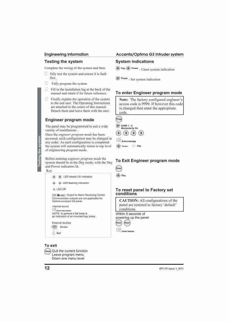
Testing the system
Complete the wiring of the system and then:
� fully test the system and ensure it is faultfree.
� Fully program the system
� Fill in the installation log at the back of themanual and retain if for future reference.
� Finally explain the operation of the systemto the end user. The Operating Instructionsare attached to the centre of this manual.Detach them and leave them with the user.
Engineer program mode
The panel may be programmed to suit a widevariety of installations. .
Once the engineer program mode has beenaccessed, each configuration may be changed inany order. As each configuration is completedthe system will automatically return to top levelof engineering program mode.
Before entering engineer program mode thesystem should be in the Day mode, with the Dayand Power indicators lit.
Key
To exit
System indications
- Unset system indication
- Set system indication
To enter Engineer program mode
Note: The factory configured engineer’saccess code is 9999. If however this codeis changed then enter the appropriatecode.
To Exit Engineer program mode
To reset panel to Factory setconditions
CAUTION: All configurations of thepanel are restored to factory ‘default’conditions.
12 4PI175 issue 1_6/01
Engineering information Accenta/Optima G3 Intruder system
Testi
ng
the
syste
m
Reset
Day
Prog
9 9 9 9
Tamper Day
ZONE 1 - 8Momentarily On
Acknowledge
Power
Day Power
Reset Quit the current functionLeave program menuDown one menu level
LED steady On indication
LED Off
Strobe
Bell
NOTE: In general a flat beep isan indication of an incorrect key press.
Sound description
Internal sound
External devices
ARCo/p Output to Alarm Receiving Centre
Communicator outputs are not applicable forOptima compact G3 panel
LED flashing indication
reset beeps
Within 5 seconds ofpowering up the panel
Reset Reset

Access Codes
There are four codes used in the system, all are 4digit and can be set to any number from 0000 to9999. The access codes ensure that onlyauthorised users can operate the system.
User 1 and 2 codes
The user 1 and user 2 codes have the sameoperation for testing, Setting and Unsetting, butuser 1 code which is usually considered to be theManagers code has the authority to add, changeor delete the user 2 code and duress code.
Duress code
Should be used in a hold up situation wherethere is pressure to Set or Unset the system.Entry of the code will allow the system to worknormally but also generate a silent PA typealarm by operating the PA communicator output.
Engineer code
Accesses the Engineer Program mode to allowthe system to be programmed. The engineercode will not set or unset the system.
If configured the Engineers access code can beused to reset the system after an alarm.
Note: Entering an invalid user code willoperate the code tamper. After nineteenincorrect key pushes a full alarmcondition will be generated.
4PI175 issue 1_6/01 13
Accenta/Optima G3 intruder system Engineering information
Access
Co
des
Reset
Reset
Codes
Change User code 1
Change User code 2
Change Duress code
Change Engineer code
2
3
9
1
8
ZONE 1-4
n n n n New code
ZONE 1-4
Rising beeps
Attack
Exit codes
Leave engineer mode
Day Tamper
Attack
Acknowledge
Day
Day
NOTE - The sounder will producea flat beep if the code is rejected. The Codeis rejected if it is already in use.
Enter Engineer program mode
Example: To change User 1 code to 3457Press:
9Prog 9 9 9
4 Reset Reset
8 1
3 5 7

Programs
The panel uses 3 Part Set routines known asPrograms. In each Program the exit mode can bechanged and the zone may be set up to have adifferent function.
The examples below show how 3 typicalPrograms could be used in a house.
� Program 1 : To arm all of the zones andbecome Set as the user leaves the propertyand closes the final door.
� Program 2 : To protect the perimeter of theproperty in the evening and become Setafter say 20 seconds.
� Program 3 ; To protect the downstairsareas of the house at night and become Setinstantly and silently.
Note: The above are purely examples.The installer must program the panel toconfigure all the circuits to thecustomer’s exact requirements.
Zone Function per Program
Timed : This function would be used to protectthe main entry/exit door of the entry route.
Time inhibited : This is a zone which, onsetting the panel, allows access to the Entry /Exit zone. However, if the panel is set and antime inhibited zone is triggered before an Entry/Exit zone then an alarm will be generatedimmediately.
Immediate: This is a zone which will, whenentered, go into alarm when the panel is set.
Unused : A zone that is programmed as anUnused zone by the Engineer, then is ignored bythe panel. Primarily used for Part set options.
Exit Modes program
Timed A timed Program will become Set as theExit timer expires.
Terminated Set
This sets an infinite time out, which will onlyset once the PTS input is operated.
Final Door A final door program will be Set 5seconds after a timed zone has opened andclosed.
Silent Set This operates exactly the same as‘Timed’ but completely silent without theinternal sounder signal.
Note: If a program is not selected whenthe user Sets the system, Program 1 willautomatically Set. Therefore Program 1is usually considered as the Full SetProgram containing all of the zones.
14 4PI175 issue 1_6/01
Engineering information Accenta/Optima G3 Intruder system
Pro
gra
ms

Programs 1,2 and 3
4PI175 issue 1_6/01 15
Accenta/Optima G3 intruder system Engineering information
Pro
gra
ms
1,2
an
d3
Reset
Reset
ProgSet upprogram
Program 1
2
3
1
Program 2
Program 3
Used Zones
Timed Zones
Time inhibitzones
Exit time
Exit mode
5
6
2
3
4
1
Disabled
Terminated set
Final Door Set
Silent set(use exit time)
2
3
4
0
Attack
Zone 1
Zone 2
Zone 3
Pre
ss
nu
mb
er
bu
tto
nto
se
lec
tP
rog
ram
tob
ec
on
fig
ure
d
All Zones
Zone 2
Zone 1
Zone 2
Entry time
Day
Factory default
Zone 4
Zone 3
Zone 2
Pre
ss
an
um
be
rb
utt
on
tos
ele
ct
the
ap
pro
pri
ate
Ex
itm
od
e
Day
Zone 1 Day
Day
Day
Input Entry/Exit timerespectively
0 1
0 2
0 3
20 seconds duration
Acknowledge
10 seconds duration
30 seconds duration(factory default)
Zone nselected
Zone ndeselected
5
6
7
2
3
4
1
8
Zone 1
Zone 2
Zone 3
Zone 4
Zone 5
Zone 6
Zone 7
Zone 8
AppropriateZone indicatoris lit to showselectedzones
Pre
ss
nu
mb
er
bu
tto
nto
se
lec
t/
de
se
lec
tzo
ne
0 Deselect all zones
Factory defaults
Leave engineer mode
Day Tamper
Attack
Acknowledge
Exit to Setup program
Exit Set up program
Exit to Program andcomplete used zone set up
Day
Day
Zones 1,2 and 3
Enter Engineer program mode
Timed1 Zone 1 forProgram 1
For Programs2 and 3
Reset
Reset
Example: To configure Program 1 Exit mode to Final door set, Press:
Prog 1Prog 9 9 9 9 3 Reset Reset ResetReset6

Alarm and Walk tests
The alarm test function allows you to test theStrobe, Bell, Low and high volume sounders ofthe system.
The walk test function allows each detector to bechecked in order to verify that they arefunctioning correctly.
16 4PI175 issue 1_6/01
Engineering information Accenta/Optima G3 Intruder system
Ala
rman
dW
alk
tests
Alarm test1
Attack
x1 for zone 1x2 for zone 2
|x4 for zone 4flat x1 for zone 5flat x2 for zone 6
|flat x4 for zone 8
Rapid for PA
Rapid for Tamper
Zones
Strobe
Strobe test2
Bell test3
Low volumesounder
High volumesounder
4
5
Walk test6
Strobe On
Bell on
internal lowvolume sound
internal highvolume sound
Strobe On
Day
Day
Day
Day
Day
OFF0 Day
Exit current level
Leave engineer mode
Day Tamper
Attack
Acknowledge
Appropriate zone lightsare lit(latched)
Attack
Tamper
Press zero to turn offoptions 2,3,4 and 5before selecting a new one
Enter Engineer program mode
Reset
Reset
Example: To start bell test and thereafter to stop bell test.
3Prog 9 9 9 9 0 Reset1 Reset

Communicator tests
Note: These tests are not applicable toOptima compact G3 panel.
The Zone 8 LED is lit to show there is acommunicator line fault.
‘Flag A’ Options
4PI175 issue 1_6/01 17
Accenta/Optima G3 intruder system Engineering information
Co
mm
un
icato
rte
sts
CommunicatorTests
Fire Output
2 PA Output
3IntruderOutput
Open /CloseOutput
4
5 Abort Output
ConfirmedOutput
6
1
2
Attack
Zone 1
Zone 2
Zone 3
Zone 4
Zone 5
Zone 6
0 Stop the tests
Pre
ss
nu
mb
er
bu
tto
nto
sele
ct
/d
esele
ct
test
AppropriateZone indicatoris lit to show aselected output
Factory defaults
Exit current level
Leave engineer mode
Day Tamper
Attack
Acknowledge
Zone 8Communicator fault
Enter Engineer program mode
Reset
Reset
Example: To test intruder outputand thereafter stop the test.
3Prog 9 9 9 9
0 Reset
2
Reset
Flag A descriptions:
Silent PA : When this flag is set and onoperating PA will cause a Silent PA alarm.
RKP PA Enable: When this flag is set thekeypad PA buttons are enabled.
Engineer Reset: When this flag is set anEngineer code must be entered to reset thesystem after a full alarm. When the flag is clearthe system can be reset by the user.
Anti-code Reset: When this flag is set it enablesthe anti code reset function.
Enable Door bell on PTS: When this flag is setit allows a zone circuit programmed as PTS tooperate as a door bell.
Enable single key setting:When this flag is setit allows the panel to be set by pressing the SETbutton (ie code entry is not needed), however a 4digit code is needed to Unset the panel.
Enable strobe on setting: When this flag is setthe external strobe will flash for 3 seconds oncethe panel has successfully set.
Enable external Fire bell: When this flag is setthe system bell will sound 3 seconds On / 3seconds Off during a fire alarm.
Zone 1
Zone 2
Zone 3
Zone 4
Zone 5
Zone 6
Zone 7
Zone 8
Flags A
Silent PA
RKP PA enable
Engineer reset
Anti-code reset
Enable Door bellon PTS
5
Enable singlekey setting
6
Enable strobeon setting
7
2
3
4
1
Enable Bellin Fire
8
3
Attack
Factory defaults
AppropriateZone indicatoris lit to showflag setting
Exit current level
Leave engineer mode
Day Tamper
Attack
Acknowledge
Zones 1-8Momentarily On
Pre
ss
nu
mb
er
bu
tto
nto
sele
ct
/d
esele
ct
flag
sett
ing
Enter Engineer program mode
Reset
Reset
Example: To set the panel forengineer reset, Press:
3Prog 9 9 9 9
Reset
3
Reset

‘Flag B’ options
Note: The following settings:Communicator output, Line Fail,Program 1, 2 and 3 to report are notapplicable to Optima compact G3 panel.
Viewing the event log
18 4PI175 issue 1_6/01
Engineering information Accenta/Optima G3 Intruder system
‘Fla
gB
’o
pti
on
s
Flags B
Communicatoroutput active high
Line fail activehigh
User Reset PA
User Reset Fire
Program 1to report
Program 2to report
Program 3to report
5
6
7
2
3
4
1
4
Factory defaults
Zone 1
Zone 2
Zone 3
Zone 4
Zone 5
Zone 6
Zone 7
Attack
AppropriateZone indicatoris lit to showflag setting
Exit current level
Leave engineer mode
Day Tamper
Attack
Acknowledge
Zones 1-8Momentarily On
Entry deviate8 Zone 8
Pre
ss
nu
mb
er
bu
tto
nto
sele
ct
/d
esele
ct
fun
cti
on
Enter Engineering program mode
Reset
Reset
Example: To set the panel foruser to reset PA, Press:
3Prog 9 9 9 9
Reset
4
Reset
Flag B descriptions:
Communicator output active high: When thisflag is set it configures the polarity ofcommunicator outputs to active high, that isoutput is held at 0V rising to 12V in alarm.
Line fail active high: When this flag is set itconfigures the polarity of line fail input.
User Reset PA: When this flag is set it permitsthe user code to reset the system after a PAalarm, even if Engineer reset flag is set.
User Reset Fire: When this flag is set it permitsthe user code to reset the system after a Firealarm, even if Engineer reset flag is set.
Program n to Report: When this flag is set itallows program n to activate the intruder andconfirmed outputs. (Main use is to prevent anight time program from communicating).
Entry deviate: When this flag is set it permitsan immediate zone to be activated during theentry period without causing a full alarm.
Reset
View the event logChime
5
6
7
2
3
4
1
8
View event 1(oldest event)
View event 2
View event 3
View event 4
View event 5
View event 6
View event 7
View event 8(Newest event)
Automatic event scrollStarting from event 1 to 8
To manually scroll
Resumeautomatic scroll
Zone, PA andTamper indicatorswill be lit toshow zone inalarm.Flashing indicatesthe first zone inalarm.Day indicatesstatus of panelat the time of alarm
Leave engineer mode
Stop event scroll / view
Tamper
Day TamperAcknowledge
Tamper
Enter Engineer program mode
Chime
Example: To view up to8 previous events and thereafterto stop the event scroll, Press:
ChimeProg 9 9 9 9
Reset

Zone Type
The G3 range of panels are not supplied with
wire links to terminate unused zones. Thereforeall unused zones must be programmed out bysetting them to disabled using the Zone Type
function.
4PI175 issue 1_6/01 19
Accenta/Optima G3 intruder system Engineering information
Zo
ne
Typ
e
ZoneConfiguration
Zone 1 type
Zone 2 type
Zone 3 type
Zone 4 type
Zone 5 type
Zone 6 type
Zone 8 type
5
6
8
2
3
4
1
5
Attack
All Zones
Pre
ss
an
um
be
rb
utt
on
tos
ele
ct
Zo
ne
tob
ec
on
fig
ure
d
Pre
ss
an
um
be
rb
utt
on
tos
ele
ct
zo
ne
typ
e
Day
Exit to zone type
Exit zone configuration
Leave engineer mode
Tamper
Attack
Acknowledge
Day
Disabled
Security
Fire
24h Fire
PTS
Keyswitch
4
5
1
2
3
0
Zone 5
Zone 3
Zone 2
Zone 1
Zone 4
Factory default
AppropriateZone indicatoris lit to showZone type
Acknowledge
Day
Enter Engineer program mode
Reset
Reset
Reset
Zone 7 type7
Example: To disable an unused zone 8, Press:
5Prog 9 9 9 9 0 Reset Reset Reset8

Zone Attributes
Zone attribute descriptions
Double knock: The panel will require 2activations of the same detector before causingan alarm condition. This setting is used as a falsealarm measure.
Note: Double knock must not be used onzones having magnetic door/windowcontacts.
Omit Prevent: The panel will prevent the zonefrom being omitted by the user when setting thesystem.
Zone Delay: The panel programs a zone delayto 800mS to give extra immunity to false alarms.
20 4PI175 issue 1_6/01
Engineering information Accenta/Optima G3 Intruder system
Zo
ne
Att
rib
ute
s
ZoneAttributes
Double Knock
Omit Prevent
Zone Delay
2
3
1
6
Attack
Zone nselected
Zone ndeselected
5
6
7
2
3
4
1
8
Zone 1
Zone 2
Zone 3
Zone 4
Zone 5
Zone 6
Zone 7
Zone 8
Pre
ss
nu
mb
er
bu
tto
nto
se
lec
t/
de
se
lec
tzo
ne
de
lay,
Om
itzo
ne
or
Do
ub
lek
no
ck
0 Deselect all zones
ZONE 1 - 8Momentarily On
AppropriateZone indicatoris lit to showzone having800mS delay,Omit preventor double knock.
Factory defaults:
All zones havedelay of 300mS
No Zones areset as omit prevent
No zones arein double knock
Day
Enter Engineer program mode
Exit to zone type
Exit zone attributes
Leave program mode
Tamper
Attack
Acknowledge
Day
Day
Reset
Reset
Reset
Example: To configure zones 4 and 5 for ‘Double knock’ operation, Press:
6Prog 9 9 9 9 5 Reset Reset Reset1 4

Bell and Service Timers
4PI175 issue 1_6/01 21
Accenta/Optima G3 intruder system Engineering information
Bell
an
dS
erv
ice
Tim
ers
Reset
Reset
Reset
Anti-codereset site code
Zone 1
Zone 2
0 0
0 1
0 2
0 3
2 0
Continous operation
1 minute bell duration
3 minute bell duration
20 minute bell duration(factory default)
9 9 99 minute bell duration
2 minute bell duration
Zone 1
Zone 2
0 0
0 1
0 2
0 3
2 0
No delay(Factory default)
1 minute bell duration
3 minute bell duration
20 minute bell duration
9 9 99 minute bell duration
2 minute bell duration
Acknowledge
100 Set/Unset1 Zone 1
Pre
ss
an
um
be
rb
utt
on
tos
ele
ct
Se
rvic
eti
me
r 300 Set/Unset3 Zone 3
200 Set/Unset2 Zone 2
500 Set/Unset5 Zone 5
400 Set/Unset4 Zone 4
600 Set/Unset6 Zone 6
800 Set/Unset8 Zone 8
700 Set/Unset7 Zone 7
Service timer disabled(Factory default)
0
Lit when selected
Timers andCounters
Bell timer
Bell delay timer
Service timer
Re-arm counter(00 to 99)
2
3
4
1
5
7
Attack
Leave engineer mode
Exit Timer and counters
ZONE 1 - 8Momentarily On
AppropriateSet / Unsetvalues LED islit
Exit
Day
Day
Day
Attack
Day TamperAcknowledge
Day
Enter Engineer program mode
Example: To set bell timer for 10 minutes duration, Press:
7Prog 9 9 9 9 0 Reset Reset1 1

Re-arm and Anticode reset code
Re-arm
After an alarm the panel will automatically resetitself when the bell timer has expired. Any zoneswhich still remain open at that time will beomitted automatically.
Note: By default there are 3 automaticre-arms before the panel is shut down.
Anti code reset (Engineer reset)
If the system has been programmed to beengineer reset, after an alarm it will lock out andthe RKP will continually display the cause of thealarm. The engineer would then be required toattend the site and use the engineer code to resetthe system.
Where anti-code reset has also been enabled, theRKP will still show the alarm cause and alsodisplay a 4 digit 'quote code' by sequentiallyflashing zone indicators 1-8.
At this point the end user would contact theengineer. After determining the cause of thealarm and deciding that a engineer call was notnecessary, a 6 digit anti-code would be given tothe user which would reset the system.
This anti-code is generated from a smallcomputer program which is installed at most UKAlarm receiving Centres, or alternatively can berun on a PC by the engineer.
Security of the anti-code reset system ismaintained by a 2 digit site code which is set upin the anti-code generator programme. The same2 digit site must also be set up in the controlpanel during installation.
22 4PI175 issue 1_6/01
Engineering information Accenta/Optima G3 Intruder system
Re-a
rman
dA
nti
co
de
reset
co
de
Reset
Reset
Anti-code reset site code
Zone 1
Zone 2
Acknowledge
0 0
0 1
2 0
factorydefaultcode
01
20
9 9 99
Timers andCounters
Bell timer
Bell delay timer
Service timer
Re-arm counter(00 to 99)
2
3
4
1
5
7
Attack
Day
0 0
0 1
0 3
No re-arm
1 re-arms
3 re-arms(factory default)
9 9 99 re-arms
Leave program mode
Attack
Day TamperAcknowledge
Day
Zone 1
Zone 2
Day
Enter Engineer program mode
Exit to Timer and counters
Example: To set panel re-arms to10 times before panel is shut down, Press:
7Prog 9 9 9 9 0 Reset Reset4 1

Lighting controller
4PI175 issue 1_6/01 23
Accenta/Optima G3 intruder system Engineering information
Lig
hti
ng
co
ntr
oller
Prog
Reset
Reset
Reset
Reset
Reset
LightingController
Channel 1assigned zones
5
6
7
2
3
4
1
Channel 2assigned zones
Channel 3assigned zones
Channel 4assigned zones
Channel 5assigned zones
Channel 6assigned zones
Channel 7assigned zones
Channel 8assigned zones
8
Set the light thresholdlevel (0 - 99%)
Hold time(20 seconds factory default)
(0-99 seconds)
9
9
Pre
ss
an
um
ber
bu
tto
nto
sele
ct
the
ap
pro
pri
ate
lig
ht
ch
an
nel
All Zones
5
6
7
2
3
4
1
8
To assign zones to channelpress to select andagain to deselect zone(Factory default: No zonesare selected)
Zone nassigned to the channel
Zone nnot assigned to the channel
AppropriateZone indicatoris lit to identifyits assignment tochannel
Exit Lighting controller
Exit current level
Leave program mode
Day Tamper
Attack
Acknowledge
Day
Attack
Zone 1
Zone 2
Day
0 0
0 1
2 0
0% threshold or0 second hold time acknowledge
20% threshold or20 seconds hold time
1% threshold or1 second hold time
Day
Exit Lighting controller
Leave program mode
Day
Tamper
Attack
Acknowledge
Enter Engineer program mode
Example: To assign zones 1 and 2 to lighting controller channel 1, Press:
9Prog 9 9 9 9 2 Reset Reset Reset1 1
Faults
Fault conditions are often the result of minorinstallation errors or misinterpretation of theequipment being installed. The following pointsoutline the most common installation andcommissioning faults.
a. As supplied the user code is 0123 andthe engineer code is 9999. Both codeswill revert back to these default settingson clearing the NVM.
b. The Engineer Program is accesseddirectly from Day mode via theengineer code.
c. If a tamper, PA or 24Hr fire fault ispresent on the system, it will go to alock out condition (showing theappropriate indication). The keypad willnot produce any audible responsesand the system will not operate untilthe fault has been found and rectified.
d. The most common cause of a zone notresponding to detection is incorrectwiring. Normally closed detectors mustbe wired together in a series loopbefore connecting into the appropriateZONE terminals. Tampers are serieswired in the same manner.
e. Where a permanent zone fault isshowing and the loop resistance isfound to be in order, the most probablecause is a short circuit between thezone wiring and the tamper wiring.When measured with a multimeter theseries resistance between the zoneand tamper wiring should be infinitelyhigh.
f. If totally lost as to the cause of a fault,remove ALL wiring from the PCB. Refitthe 4-links and test the system. Neverfit links to any positions other thanthose marked on the PCB.
g. Before testing or replacing any fuses,ALL power must be removed. Fuseswhich fail continually are almostcertainly the result of a short circuit orlow resistance across the 13V supplyor external bell supply (terminal D).
h. Whenever working close to the mainssupply or connector, you shouldexercise extreme caution.Always isolate the mains supply beforeremoving the control panel covers.
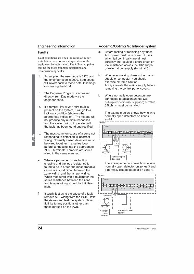
i. Where normally open detectors areconnected to adjacent zones twopull-up resistors (not supplied) of value33kohms must be installed.
The example below shows how to wirenormally open detectors on zones 3and 4.
The example below shows how to wirenormally open detector on zones 3 anda normally closed detector on zone 4.
24 4PI175 issue 1_6/01
Engineering information Accenta/Optima G3 Intruder system
Fau
lts
J2
21 43 65 87
Panel
PA+ -
TAMP +13V 0V
Board
Normally opendetectors
33Kohms
J2
21 43 65 87
Panel
PA+ -
TAMP +13V 0V
Board
Normallyopen
detector
Normally closeddetector
33Kohms

j. Where Pressure mats are being usedthese must be connected to a zone inthe manner shown. The example belowshows pressure mats connected tozones 3.
Specification
Indicators onControl panel orRKPs
Zone 1-8, Power, Attack,Tamper and Day
8 Zones+ve loop, programmablefunction in each program
Tamper-ve loop, internalsounders in Day – Fullalarm in Set
PA +ve loop, always active
Bell Output12V, adjustable timer(1-99 mins) orcontinuous
Strobe Output 12V latching
Extension Speaker16 ohms (2 maximum)130mA each
Exit/Entry timersseconds
Programmable (10-990seconds)
Zone Input Delay 300 or 800mS
Set +ve Output0V in Day (sinking40mA)
CurrentConsumptionControl panel
Standby 80mA
Alarm 250mA
Currentconsumption RKP
Standby 40mA
Alarm 70mA
Low voltageoutput
13.8V dc stabilised (+/-5%) up to 350mA
RechargeableBattery
Accenta/Optima G3mini/compact - 12V, 1.2or 2.1Ah
Accenta/Optima G3- 12V, up to 7Ah
Charge Voltage 13.8V dc (+/-5%)
PCB Fuses1.6A & 1A 20mm quickblow
Mains Input fuse
125mA, 250V type T(anti-surge) typeapproved to IEC 127,part 2 sheet III
Total CurrentOutput
1Amp when supportedby a fully chargedbattery
Mains SupplyVoltage
230V (+/-10%) 50Hzmax load 0.2A
Total CurrentOutput
1Amp when supportedby a fully chargedbattery
Mains SupplyVoltage
230V (+/-10%) 50Hzmax load 0.2A
AmbientOperatingtemperature
0 –40degC
Enclosureconstruction
3mm Polycarbonate
Dimensions
Accenta/Optima G3mini/compactH 200mm W 253mmD 55mm
Accenta/Optima G3H 230mm W 290mmD 80mm
RKP H 85mm W122mm D 28mm
4PI175 issue 1_6/01 25
Accenta/Optima G3 intruder system Engineering information
Sp
ecif
icati
on
J2
21 43 65 87
Panel
PA+ -
TAMP +13V 0V
Board
Pressure Mats
33Kohms

26 4PI175 issue 1_6/01
Engineering information Accenta/Optima G3 Intruder system
Sp
ecif
icati
on
Index
!13V Supply . . . 8
24 hour fire zone . 2,6,10,19
3 Part Set . . . . 14
AAC terminals . . . 3
Access Codes. . . 13
Alarm test . . . . 16
Anti Code Reset . 10,17,22
ARC . . . . . . . 9
BBattery . . . . . . 11,25
Bell Delay . . . . 10
Bell Duration . . 10
Bell in fire . . . . 17
Bell Output . . . . 7,25
Bell timer. . . . . 21
Board . . . . . . . 4
BS 4737 1986/87 . 1
CCharge Voltage. . 25
Chime . . . . . . 2
Codes . . . . . . . 2
Communicator . . 17
Communicator Outputs8,10
Current Consumption25
DDay mode . . . . 11
Detectors . . . . . 3
Dimensions. . . . 25
Door bell . . . . . 10,17
Double knock . . 10,20
Duress Code . . . 10,13
EEngineer Code . . 10,13
Engineer program mode12,24
Engineer Reset . . 10,17
Entry deviate . . . 18
Entry time . . . . 10,15
Event log . . . . . 18
Exit Mode . . . . 10,14,15
Exit time . . . . . 10,15
Exit/Entry timers . 25
Extension speakers 7
External bell on Fire10
FFactory set conditions10,12
Faults . . . . . . . 24
Final door set . . . 14,15
Fire zone . . . . . 6,19
Flag A . . . . . . 17
Flag B . . . . . . 18
Full Set . . . . . . 14
Fuses . . . . . . . 4,24
HHold time. . . . . 23
IImmediate zone . 14
KKeyswitch zone . 10,19
Llight channel . . . 23
Light Hold Time . 10
Light threshold . . 10,23
Lighting controller 2,10,23
Line Fail . . . . . 10
Local Authorit . . 3
MMains . . . . . . . 11,25
Managers code . . 13
NNACOSS . . . . . 6,9
NACP 14 . . . . . 9
Normally closed detectors24
Normally open detector24
NVM . . . . . . . 2,9
OOmit prevent . . . 10,20
Operating temperature25
PPA . . . . . . . . 2,6,25
PA fault. . . . . . 24
PCB Fuses . . . . 25
Pressure mats . . . 25
Program 1 . . . . 10,14
Program 1 to report10,18
Program 2 . . . . 10,14
Program 2 to report10,18
Program 3 . . . . 10,14
Program 3 to report10,18
Programs 1,2 and 315
PTS zone . . . . . 2,19
Push to Set . . . . 6,10
QQuick set . . . . . 2
quote code . . . . 22
RRe-arm . . . . . . 22
Rearm counter . . 10
Red Care STU . . 2,8
Remote keypad . . 2,5
Remote keyswitch 6
RKP . . . . . . . 3,10,25
RKP PA enable. . 17
SSecurity Zones . . 5,10,19
Service counter . . 10
Service timer . . . 21
Set . . . . . . . . 8
Set system . . . . 12
Silent PA . . . . . 10,17
Silent Set . . . . . 14,15
Single key setting 10,17
Site Code . . . . . 10
Speakers . . . . . 3
Specification . . . 25,26
Standard Fire zone 6,10
Strobe on setting . 10,17
TT A D B . . . . . 7
Tamper . . . . . . 25
Tamper fault . . . 24
Tamper network . 6
Terminated Set . . 6,14,15
Time inhibited zone14,15
Timed. . . . . . . 14
Timed exit . . . . 15
Timed zones . . . 15
Total current . . . 3
UUnset system . . . 12
Unused zone . . . 14,15
User code 1 . . . 10
User 1 . . . . . . 2
User 1 and 2 codes 13
User 2 . . . . . . 2
User code 2. . . . 10
User reset fire . . 10,18
User reset PA. . . 10,18
VVolume . . . . . . 7
WWalk Test . . . . 2,16
wire links . . . . . 4
ZZone Attributes. . 20
Zone debounce . . 10
zone delay . . . . 20
Zone Input Delay. 25
Zone Type . . . . 19

Servicing organisation Details
Servicing organisation name:
_______________________________________
Telephone number:
______________________________________
Date of installation:
______________________________________
Account Number:
_____________________________________
Parts
Below is a list of approved parts and accessories.
8SP 401 Accenta G3 panel
8SP 400 Accenta mini G3 panel
8EP 395 Optima G3
8EP 396 Optima compact G3 panel
8EP 219 Accenta LED RKP
8EP 332 Accenta LCD RKP
8EP 336 Accenta Speech Dialler
8EP 276 Informa
8EP 289 Extension Speaker
8EP 372 Opti-Cam Lighting Controller
A range of detectors are also available, for moreinformation contact your supplier.
4PI175 issue 1_6/01 27
Accenta/Optima G3 intruder system Engineering information
Serv
icin
go
rgan
isati
on
Deta
ils
Resistance Area protection and equipment used (eg PIR, Contacts..)
Zone 1
Zone 2
Zone 3
Zone 4
Zone 5
Zone 6
Zone 7
Zone 8

Quick Reference
28 4PI175 issue 1_6/01
Engineering information Accenta/Optima G3 Intruder system
Qu
ick
Refe
ren
ce
The panels conform tothe requirements of theEuropean EMC andLow Voltage directives,and carries the CE mark
Re
se
tS
etup
pro
gra
m(s
ee
page
15)
Pro
gra
m1
2 31
Pro
gra
m2
Pro
gra
m3
Used
Zones
Tim
ed
Zones
Tim
ein
hib
itzones
Exit
tim
e
Exit
mode
5 62 3 41
Entr
ytim
e
Vie
wth
eeventlo
g(s
ee
page
18)
Com
munic
ato
rTests
(see
page
17)
Fire
Outp
ut
2P
AO
utp
ut
3In
truder
Outp
ut
Open
/Clo
se
Outp
ut
4 5A
bort
Outp
ut
Confirm
ed
Outp
ut
61
2A
larm
test
(see
page
16)
1F
lags
A(s
ee
page
17)
Sile
ntP
A
RK
PP
Aenable
Engin
eer
reset
Anti-c
ode
reset
Enable
Door
bell
on
PT
S5
Enable
sin
gle
key
settin
g6
Enable
str
obe
on
settin
g72 3 41
Enable
Bell
inF
ire
8
3F
lags
B(s
ee
page
18)
Com
munic
ato
routp
ut
active
hig
h
Lin
efa
ilactive
hig
h
User
ResetP
A
User
ResetF
ire
Pro
gra
m1
tore
port
Pro
gra
m2
tore
port
Pro
gra
m3
tore
port
5 6 72 3 41
4Z
one
Attribute
s(s
ee
page
20)
Double
Knock
Om
itP
revent
Zone
Dela
y
2 31
6
Str
obe
test
2
Bell
test
3
Low
volu
me
sounder
Hig
hvolu
me
sounder
4 5 6
99
99
En
gin
ee
rP
rog
ram
Mo
de
Pro
gTo
exit
en
gin
ee
rp
rog
ram
mo
de
Re
se
t
Zo
ne
Typ
e(s
ee
pa
ge
19
)
Zo
ne
1ty
pe
Zo
ne
2ty
pe
Zo
ne
4ty
pe
Zo
ne
5ty
pe
Zo
ne
6ty
pe
Zo
ne
7ty
pe
Zo
ne
8ty
pe
5 6 72 3 41
5
Dis
ab
led
Se
cu
rity
Fire
24
hF
ire
PT
S
Ke
ysw
itch
4 51 2 30
Entr
ydevia
te8
Co
de
s(s
ee
pa
ge
13
)
Ch
an
ge
Use
rco
de
1
Ch
an
ge
Use
rco
de
2
Ch
an
ge
Du
ress
co
de
Ch
an
ge
En
gin
ee
r’s
co
de
2 3 91
8
An
ti-c
od
ere
se
tsite
co
de
Tim
ers
an
dC
ou
nte
rs(s
ee
pa
ge
21
&2
2)
Be
lltim
er
Be
lld
ela
ytim
er
Se
rvic
etim
er
Re
-arm
co
un
ter
(00
to9
9)
2 3 41 5
7
Lig
hting
Contr
olle
r(s
ee
page
23)
Channel1
assig
ned
zones
5 6 72 3 41
Channel2
assig
ned
zones
Channel3
assig
ned
zones
Channel4
assig
ned
zones
Channel5
assig
ned
zones
Channel6
assig
ned
zones
Channel7
assig
ned
zones
Channel9
Hold
tim
e(0
-99s)
8
Pro
gS
etth
elig
htth
reshold
level(0
-99%
)
9
9
Dis
ab
led
Te
rmin
ate
dse
t
Fin
alD
oo
rS
et
Sile
nt
se
t(u
se
exit
tim
e)
2 3 40
Tim
ed
1
Channel8
assig
ned
zones
Pro
gC
him
e
Walk
test
For Technical Support
� : 0151 549 1550

Intruder alarm system
Operating Instructions
Key
These operatinginstructions cover thefollowing intrudersystem:
� 8SP 401 Accenta G3panel with remoteLED keypad
� 8SP 400 Accentamini G3 panel withremote LED keypad
� 8EP 395 Optima G3panel with built inkeypad
� 8EP 396 Optimacompact G3 panelwith built in keypad
For Clarity, theinformation given onsetting the system,assume that all Programsuse a timed or final doorsetting routine.
Unset system indications
An unset system will have both Day and Powerindicators lit. This is a normalindication when the system is
disarmed.
Note: If the Power indicator goes off atany time then there is a mains supplyfailure at the security panel, consult yourservicing organisation.
Set System indication
An active ‘Set’ system will have only the Powerindicator lit. This is an armedsystem indication.
4PI175 issue 1_6/01 1
Un
set
syste
min
dic
ati
on
s
0 1 2 3
5 6 7 8
Chime Omit Reset
4
9
SetProg
ZONE 1
ZONE 2
ZONE 3
ZONE 4
ZONE 5
ZONE 6
ZONE 7
ZONE 8
Tamper
Attack
Day Power
PA
Accenta
0 1 2 3
5 6 7 8
Chime Omit Reset
4
9
SetProg
ZONE 1
ZONE 2
ZONE 3
ZONE 4
ZONE 5
ZONE 6
ZONE 7
ZONE 8
Tamper
Attack
Day Power
PA
Accenta
Power 0 1 2 3
5 6 7 8
Chime Omit Reset
4
9
SetProg
PA
Attack
Tamper
Day
1 2 3 4 5 6 7 8
8EP 396 Optima compact G3 panelwith built-in keypad
Power
Accenta�� ����
0 1 2 3
5 6 7 8
Chime Omit Reset
4
9
SetProg
PA
Attack
Tamper
Day
1 2 3 4 5 6 7 8
Remote LED keypad
LED steady On indication
LED Off
Strobe
Bell
NOTE: In general a flat beep isan indication of an incorrect key press.
Sound description
Internal sound
External devices
ARCo/p Output to Alarm Receiving Centre
Communicator outputs are not applicable forOptima compact G3 panel
LED flashing indicationDay Power
Power

Access codes
There are two User codes used in the system, allare 4 digit and can be set to any number from0000 to 9999, signified by:
The user 1 and 2 codes have the same operationfor testing, Setting and Unsetting, but user 1code which is usually considered to be theManagers code has the authority to add, changeor delete the user 2 code and Duress code.
� User 1 code - 0123 factory set
� User 2 code - not programmed.
How to operate Personal Attack
Personal Attack buttons on the keypad are usedto activate the alarm, irrespective of whether thesystem is armed or not.
Press Simultaneously:
How to unset system in alarm
Enter your code. Entering the code will turn thealarm off and the cause of the alarm will bedisplayed. After investigation press Reset toclear the indication.
Note: If the alarm indication does notclear, then the system may need to bereset by the installation engineer, contactyou installer for further information.
Programs 1, 2 and 3
The panel uses 3 Part Set routines known asPrograms. In each Program the exit mode can bechanged and the zone may be set up to have adifferent function.
The examples below show how 3 typicalPrograms could be used in a house.
Program 1 To arm all of the zones and becomeSet as the user leaves the property and closes thefinal door.
Program 2 To protect the perimeter of theproperty in the evening and become Set after say20 seconds.
Program 3 To protect the downstairs areas ofthe house at night and become Set silently.
The above are purely examples. The installer hasthe ability at the programming stage to configureall the circuits to the customer’s exactrequirements.
2 4PI175 issue 1_6/01
Operating instructions Accenta/Optima G3 Intruder system
Access
co
des
ContentsUnset system indications - - - - - - - - - - - 1
Set System indication - - - - - - - - - - - - 1
Access codes - - - - - - - - - - - - - - - - 2
How to operate Personal Attack - - - - - - 2
How to unset system in alarm - - - - - - - 2
Programs 1, 2 and 3 - - - - - - - - - - - - - 2
How to set the system (on program 1) - - - 3
Push to Set Switch - - - - - - - - - - - - - - 3
Keyswitch Set - - - - - - - - - - - - - - - - 3
Faults during setting - - - - - - - - - - - - - 3
How to unset the system (turn off) - - - - - 3
How to set program1,2 or 3- - - - - - - - - 3
How to Quick set - - - - - - - - - - - - - - 4
How to Omit zone(s) on setting system - - - 4
Fire Alarm - - - - - - - - - - - - - - - - - 4
How to set Chime zone - - - - - - - - - - - 4
Operator’s Program mode - - - - - - - - - - 5
To exit operation at any time - - - - - - - - - 5
How to enter Operator’s program mode - - 5
How to view the event log - - - - - - - - - - 5
How to create/omit User 2 code - - - - - - - 6
How to change current user code - - - - - - 6
How to create/change/omit the Duress code - 6
How to carry out Alarm and Walk tests- - - 7
Servicing organisation details - - - - - - - - - 7
Quick Reference - - - - - - - - - - - - - - - 8
4 9
n n n n
Reset
n n n n
Bell
Alarm
FIRST ZONE IN ALARM
OTHER ZONES IN ALARM
Investigate the Alarm
Strobe Off
ALL ZONE
Day

How to set the system (onprogram 1)
The green Day indicator should be showing.Enter your codenumber and checkthat the system isclear (none of thezone indicatorsare showing). Thesounder will nowproduce an exitbeep tone and youshould leave bythe approved
route. The system will Set as the beep tone stops.
Push to Set Switch
In some systems a Push to Set switch may befitted outside the premises near to the main exitdoor. This should be used to complete the settingprocedure once the building has been vacated.As the switch is operated, the exit beep tone willstop and a chime tone will be produced toacknowledge setting.
Keyswitch Set
Your system may have been fitted with a remotekeyswitch. This can be used as an alternative toarming the system with a code and will setProgram 1.
Where a keyswitch is used it may be necessaryon occasions to allow it to catch up with thesystem. For example if the alarm was set with acode, to Unset with the keyswitch, it would haveto be momentarily turned to Set then returned toUnset.
Faults during setting
If the system is not clear when you try to Set it,the sounder will produce an open zone tone andthe fault will be displayed. Either re-enter yourcode to turn off and investigate or omit the faultyzone(s) from the system.
How to unset the system (turnoff)
On entering the premises an entry beep tonecomes on. Enter your code, the green Dayindicator is lit. The system is unset anddisarmed.
How to set program1,2 or 3
The green Day indicator should be showing.Enter your codenumber and theexit beep tonewill start. Pressthe Prog key andthe exit tone willstop. Press 1, 2or 3 for therequiredprogram, thesounder willbeep toacknowledge theprogram number.
The exit beep tone will start and you shouldleave by the approved route. The system will Setas the beep tone stops.
It is important that you follow the correctprocedure when setting the system. After leavingthe protected area it is absolutely essential thatyou wait until the exit tone stops, beforeassuming the system has set.
4PI175 issue 1_6/01 3
Accenta/Optima G3 intruder system Operating instructions
Ho
wto
set
the
syste
m(o
np
rog
ram
1)n n n n
Day
Day
Acknowledge
ARCo/p
Unset output
Entry beep
n n n
Day
Day
10secondsinsistent beeps
Exit beep
n
ARCo/p
Set output
Prog
n n n n
Day
321 Or
Day
Exit beep
Exit beep 10 secondsinsistent beeps
ZONE 1-3 Exit beep
ARCo/p
Set output

How to Quick set
During the exit period (on entering User code)the system may be Setquickly by pressing Set.This removes the exit timeperiod.
If you omit zones andrequire Quick Set, you willneed to press Set twice.
How to Omit zone(s) on settingsystem
During the exit period after entering User codeand selecting aprogram pressOMIT, the exit tonewill stop and zonesthat are about to bearmed will bedisplayed. Key inthe zone number(s)to be omitted whichwill flash to confirmselection. Zoneindicators whichshow steady are stillabout to be armed.When the selectionis complete pressSet and the exit tonewill start.
If a zone refuses to be omitted, it may bebecause the engineer has programmed the panelto prevent you from turning off the zone. If indoubt ask your installer for advice.
Fire Alarm
The fire zone will operate on detection of a fire,whether the system is Set or Unset, whenconfigured as a 24 hour zone, and cause adistinctive internal sounder tone. The externalsounders will pulse on and off at 2 secondintervals and all keypad indicators will flash toattract attention.
How to set Chime Zones
Chime is a low security monitoring system foruse when the system is Unset. When a zone thatis set to chime is operated, the internal sounderwill produce a low volume two stage warningtone and the Zone indicator will show. Theindicator may be cancelled by pressing Reset.
Chime is particularly useful in a shop to warn ofa customer presence or in a house to warn that adoor or particular area has been accessed.
Any zone may set to be on or off chime bypressing the CHIME key and then keying in therequired zone number(s). Key 0 to cancel allzones from chime. After a few seconds thesystem will automatically return to the Daymode.
4 4PI175 issue 1_6/01
Operating instructions Accenta/Optima G3 Intruder system
Ho
wto
Qu
ick
set
Set
Set the system orSet a Program
Day
Day
5 secondsinsistent beeps
ARCo/p
Set output
Set
Omit
Day
Set the system orSet a Program and while thesystem is setting:
ZONE(S) TO BE ARMED
nPress the zone(s)to be omitted
ZONE(S) TO BE OMITTED
Exit beep
Exit beep 10 secondsinsistent beeps
Day
ARCo/p
Set output
Chime
Reset
Day
Day
Timeout after 5 seconds ifno selection is made
Chime
5
6
7
2
3
4
1
8
Pre
ss
nu
mb
er
bu
tto
nto
se
lec
t/
de
se
lec
tZ
on
eC
him
e
0Deselect all zones(Factory default - no chime)
Zone nChime selected
Zone nChime deselected
Zone 1
Zone 2
Zone 3
Zone 4
Zone 5
Zone 6
Zone 7
Zone 8
AppropriateZone indicatoris lit to showchime zone(s)
Leave chime mode
Day
Example: To set zone 3 and 4 tochime, Press:
Chime 3 4 Reset

Operator’s Program mode
The information below shows the programmableoptions available and how to change them.
Once the programming mode has been accessed,each section may be changed in any order. Aseach operation is completed the system willautomatically return to top level of programmode.
Note: When programming the systemshould be in the Day mode, with the Dayand Power indicators lit.
To exit operation at any time
On pressing the Reset key you will quit thecurrent level of operation.
How to enter Operator’s programmode
To enter the Operator’s program mode thesystem should be in Daymode with the Day andPower indicator lit.
How to view the event log
The panel can hold up to 8 previous eventswhich can be scrolled automatically or manually.The automatic scroll starts with the newest event( number 8) to the oldest one ( number 1).
4PI175 issue 1_6/01 5
Accenta/Optima G3 intruder system Operating instructions
Op
era
tor’
sP
rog
ram
mo
de
Reset Quit the current functionLeave Engineering menuDown one menu level
Prog
0 1 2 3
Tamper Day
ZONE 1 - 8Momentarily On
Acknowledge
Reset
View the event logChime
5
6
7
2
3
4
1
8
View event 1(oldest event)
View event 2
View event 3
View event 4
View event 5
View event 6
View event 7
View event 8(Newest event)
Automatic event scrollStarting from event 1 to 8
To manually scroll
Resumeautomatic scroll
Zone, PA andTamper indicatorswill be lit toshow zone inalarm.Flashing indicatesthe first zone inalarm.Day indicatesstatus of panelat the time of alarm
Leave program mode
Stop event scroll / view
Tamper
Day TamperAcknowledge
Tamper
Enter Operator’s program mode
Chime
Example: To view up to8 previous events and thereafterto stop the event scroll, Press:
ChimeProg 0 1 2 3
Reset

How to create/omit User 2 code
User 1 code which is usually considered to bethe Managerscode has theauthority to add,change or deletethe user 2 code.
How to change current user code
You can change the current user 1 or user 2code for securityreason.
How to create/change/omit theDuress code
The Duress code is used in a hold up situationwhere there is pressure to Set or Unset thesystem. Entry of the code will allow the systemto work normally but also generate a silent PAtype alarm by operating the PA communicatoroutput. The duress code in not preprogrammedand can be created.
6 4PI175 issue 1_6/01
Operating instructions Accenta/Optima G3 Intruder system
Ho
wto
cre
ate
/om
itU
ser
2co
de
Reset
Change / omit User code 2(By user 1 only)
7
ZONE 1-4
n n n n New code
Or
Omit To omit the user 2 code
ZONE 1-4
Rising beeps
Attack
Leave program mode
Day Tamper
Attack
Acknowledge
NOTE - The sounder will producea flat beep if code is rejected.
Enter Operator’sprogram mode
Example: To create user 2code 4567, Press:
Prog 0 1 2 7
Reset
3
4 5 6 7
Reset
Change the code of Currentuser (either User 1 or User 2)
8
ZONE 1-4
n n n n
Current user new code
ZONE 1-4
Rising beeps
Attack
NOTE - Factory default code forUser 2 is not programmed
Leave program mode
Day Tamper
Attack
Acknowledge
NOTE - The sounder will producea flat beep if code is rejected.
Enter Operator’s program mode
Example: To change user 1code from 0123 to 7777, Press:
Prog 0 1 2 8
Reset
3
7 7 7 7
Reset
Change / Omit the DuressCode (By user 1 only)
9
ZONE 1-4
n n n n
New duress code
ZONE 1-4
Rising beeps
Attack
Leave program mode
Day Tamper
Attack
Acknowledge
Enter Operator’sprogram mode
Example: To createduress5555, Press:
Prog 0 1 2 9
Reset
3
5 5 5 5

How to carry out Alarm and Walktests
The alarm test functionallows you to test theStrobe, Bell, Low andhigh volume soundersof the system.
The walk test functionallows each detector tobe checked in order toverify that they arefunctioning correctly.
Servicingorganisation details
Servicing organisation name:
______________________________________
Telephone number:
______________________________________
Date of installation:
______________________________________
Account Number:
______________________________________
Installation Date:
______________________________________
Bell Time:_____________________________
Bell delay______________________________
Areaprotected
Program1
Program2
Program3
Zone 1
Zone 2
Zone 3
Zone 4
Zone 5
Zone 6
Zone 7
Zone 8
T = Timed (Entry/Exit - Zone)
TI = Time Inhibited (Access zone to keypad)
I = Immediate (All zones armed to give fullalarm)
4PI175 issue 1_6/01 7
Accenta/Optima G3 intruder system Operating instructions
Ho
wto
carr
yo
ut
Ala
rman
dW
alk
tests
Reset
Reset
Alarm test0
Attack
x1 for zone 1x2 for zone 2
|x4 for zone 4flat x1 for zone 5flat x2 for zone 6
|flat x4 for zone 8
Rapid for PA
Rapid for Tamper
Zones
Strobe
Strobe test2
Bell test3
Low volumesounder
High volumesounder
4
5
Walk test6
Strobe On
Bell on
internal lowvolume sound
internal highvolume sound
Strobe On
Day
Day
Day
Day
Day
OFF0 Day
Exit current level
Leave program mode
Day Tamper
Attack
Acknowledge
Appropriate zone lightsare lit(latched)
Attack
Tamper
Press zero to turn offoptions 2,3,4 and 5before selecting a new one
Enter Operator’s program mode
Example: To start bell test and thereafter to stop bell test.
3Prog 0 1 2 3 0 Reset0 Reset

Quick Reference
8 4PI175 issue 1_6/01
Operating instructions Accenta/Optima G3 Intruder system
Qu
ick
Refe
ren
ce
The panels conform to therequirements of theEuropean EMC and LowVoltage directives, andcarries the CE mark
Reset
Reset
Leave
pro
gra
mm
ode
Reset
No
rma
lin
dic
ati
on
so
fa
nU
ns
et
sy
ste
m
Da
yP
ow
er
Reset
To
Re
se
tA
larm
sta
te
nn
nn
Be
ll
Ala
rm
FIR
ST
ZO
NE
INA
LA
RM
OT
HE
RZ
ON
ES
INA
LA
RM
Inve
stig
ate
the
Ala
rm
Str
ob
eO
ff
AL
LZ
ON
E
Da
y
nn
n
Da
y
Da
y
10
se
co
nd
sin
sis
ten
tb
ee
ps
To
Se
tth
esyste
m(P
rog
ram
1)
Ex
itb
ee
p
n
AR
Co
/p
Se
to
utp
ut
Pro
g
To
Se
ta
Pro
gra
m
nn
nn
Da
y
32
1O
r
Da
y
Ex
itb
ee
p
Ex
itb
ee
p1
0s
ec
on
ds
ins
iste
nt
be
ep
s
ZO
NE
1-3
Ex
itb
ee
p
AR
Co
/p
Se
to
utp
ut
Set
To
Qu
ick
Se
tth
esyste
m
Se
tth
esyste
mo
rS
et
aP
rog
ram
Da
y
Da
y
5s
ec
on
ds
ins
iste
nt
be
ep
s
AR
Co
/p
Se
to
utp
ut
To
Un
-se
tth
esyste
m
nn
nn
Da
y
Da
y
Ac
kn
ow
led
ge
AR
Co
/p
Un
se
to
utp
ut
En
try
be
ep
Ala
rmin
dic
ati
on
s
Be
llO
nS
tro
be
Set
Om
itDa
y
To
Om
itzo
ne
so
nS
ett
ing
syste
m
Se
tth
esyste
mo
rS
et
aP
rog
ram
an
dw
hile
the
syste
mis
se
ttin
g:
ZO
NE
(S)
TO
BE
AR
ME
D
nP
ress
the
zo
ne
(s)
tob
eo
mitte
d
ZO
NE
(S)
TO
BE
OM
ITT
ED
Ex
itb
ee
p
Ex
itb
ee
p
10
se
co
nd
sin
sis
ten
tb
ee
ps
Da
y
AR
Co
/p
Se
to
utp
ut
To
exit
Opera
tor’
spro
gra
mm
ode
Reset
Change
/om
itU
ser
code
2(B
yuser
1only
)
7C
hange
the
code
of
Curr
entuser
(either
User
1or
User
2)
8
nn
nn
New
code
Om
itTo
om
itth
euser
2code
nn
nn
Pro
gn
nn
nO
pera
tor’
sP
rogam
Mode
Change
/O
mit
the
Dure
ss
Code
(By
user
1only
)
9
Quit
the
curr
entfu
nction
Leave
pro
gra
mm
enu
Dow
none
menu
level
nn
nn
Vie
wth
eeventlo
gC
him
e
81V
iew
event1
(old
estevent)
Vie
wevent8
(New
estevent)
Auto
matic
eventscro
llS
tart
ing
from
event1
to8
Ch
ime
Resum
eauto
matic
scro
ll
For
manualscro
ll
Sto
peventscro
ll/vie
wE
xit
curr
entle
vel
0
Ala
rmte
st
0
Str
obe
test
2
Bell
test
3
Low
volu
me
sounder
Hig
hvolu
me
sounder
4 5
Walk
test
6
Pre
ss
zero
totu
rnoff
options
2,3
,4and
5befo
resele
cting
anew
one
Op
era
tor’
sp
rog
ram
mo
de
me
nu
ma
p
Ala
rm
Leave
pro
gra
mm
ode
Reset
Leave
pro
gra
mm
ode
Reset
Leave
pro
gra
mm
ode
Reset
Leave
pro
gra
mm
ode
Reset
Reset
Ch
ime
Ch
ime
To
se
tC
him
ezo
ne
81
Zone
tochim
e
Reset