inverse analyses in fracture mechanics.pdf
TRANSCRIPT

DOI 10.1007/s10704-006-7153-7International Journal of Fracture (2006) 138:47–73
© Springer 2006
Inverse analyses in fracture mechanics
G. MAIER∗, M. BOCCIARELLI, G. BOLZON and R. FEDELEDepartment of Structural Engineering, Technical University (Politecnico) of Milan, Milan, Italy∗Author for correspondence. (E-mail: [email protected])
Received 1 March 2005; accepted 1 December 2005
Abstract. The present purpose is a survey of some engineering-oriented research results which may berepresentative of the main issues in the title subject. Some recent or current developments are pointedout in the growing area of fracture mechanics centered on the calibration of cohesive fracture mod-els for quasi-brittle materials, by approaches which combine experimentation, experiment simulationand minimisation of the discrepancy between measured and computed quantities. Specifically, referenceis made herein to the following topics in calibration of fracture constitutive models: (a) determinis-tic characterisation of concrete-like materials by traditional three-point-bending tests (TPBTs), supple-mented by optical measurements; (b) wedge-splitting tests (WST) and extended Kalman filter (EKF)for the stochastic estimation of fracture parameters; (c) in situ parameter identification for the localdiagnosis of possibly deteriorated concrete dams on the basis of flat-jack tests; (d) fracture proper-ties of ceramic materials and coating-substrate interfaces identified through indentation tests, imprintmapping and inverse analysis in micro-technologies.
Key words: Inverse analysis, in situ experiments, interface models, non-destructive testing, parameteridentification.
1. Introduction
The quantitative assessment of constitutive parameters by inverse analysis exhib-its at present growing scientific interest and practical usefulness, as material modelsbecome more realistic and complex, and computational tools more and more pow-erful. Inverse analysis for the calibration of materials or structural models consistsof: data collection from experimental tests in laboratory or in situ; computer simula-tion of the tests by employing the model to calibrate; minimisation, with respect tothe sought parameters, of a suitable norm which quantifies the discrepancy betweenexperimental data and the corresponding values provided by the simulation. Severalaspects of the inverse problem theory and its applications are treated systematicallyin the recent literature, see e.g., Bui (1994); Stavroulakis (2000); Stavroulakis et al.(2003); Mroz and Stavroulakis (2005). A noteworthy by-product of the experimentaltest simulation is the sensitivity analysis of measurable quantities with respect to theparameters to identify: in fact, sensitivity matrices may corroborate the identifiabilityof the sought parameters and orient the optimisation of the experiment design, seeKleiber et al. (1997).
In fracture mechanics, like in other fields, inverse analysis exhibits peculiar fea-tures and represents an intersection of diverse disciplines which provide the follow-ing contributions: mathematical minimisation of generally non-convex, sometimes

48 G. Maier et al.
non-smooth discrepancy functions, with possible ill-posedness requiring special pro-visions, such as Tikhonov regularisation; sophisticated experimental mechanics foraccurate measurements; statistical methods for processing measurement and modelerrors in order to assess consequent uncertainties on the estimates; large-scale sim-ulations and computations; recourse to soft-computing, such as neural networks, inview of routine industrial use.
This paper is intended to provide a critical survey of the title subject throughbrief discussions of particular but representative practical problems in structural engi-neering and micro-technologies, recently tackled by the authors’ team with referenceto fracture properties of quasi-brittle materials described by traditional constitutivemodels, like those dealt with, e.g., by Karihaloo (1995) and Bazant and Planas(1998). More specifically, the present paper will address timely issues of model cal-ibration concerning primarily concrete dams and coated materials at the micro-scale.The case histories referred to herein are intended to evidence that also in engineeringapplications of fracture mechanics, progress may be fostered by synergistic combina-tions of experiments and their simulations for inverse analyses.
Many existing structures, particularly concrete dams built decades ago, are dete-riorated by physico-chemical ageing processes (primarily by alkali–silica reaction),and/or by past extreme loading, such as earthquakes. In order to assess presentmechanical properties crucial for structural integrity, two kinds of methodologies arecurrently adopted in engineering practice: (a) global (static or dynamic) diagnosticanalyses, intended to identify possibly deteriorated elastic moduli as damage indices(see, e.g., Ardito et al., 2004; Maier et al., 2004); (b) local diagnosis based either onin situ ‘non-destructive’ tests or on specimen extraction and laboratory tests.
Techniques of the latter local kind are considered herein (Sections 2 and 3) forthe characterisation of concrete from a fracture mechanics standpoint. In Section 2,two conventional laboratory procedures for the identification of quasi-brittle fractureparameters are referred to, namely: three-point bending test (TPBT), supplementedby electronic-speckle pattern interferometry (ESPI), combined with batch, determin-istic inverse analysis (fairly detailed descriptions available in: Bolzon et al., 1997b;Bolzon and Maier, 1998); wedge-splitting test (WST) associated to sequential, sto-chastic extended Kalman filters (EKF) (Bolzon et al., 2002). In both cases, a mode Icohesive crack model with a bilinear softening branch is adopted with four fractureparameters to identify, in accordance with CEB-FIP Model Code (1993); see also:Alvaredo and Torrent (1987); Bruhwiler and Wittmann (1990); Guinea et al. (1994).
The cohesive models and, hence, the experiments are analytically described aslinear complementarity problems (LCPs) and, therefore, the discrepancy minimisa-tion exhibits the format of ‘mathematical programming with equilibrium constraints’(MPEC), at present a recurrent mathematical construct in econometry and manage-ment and numerically solvable by new ad hoc algorithms, e.g., see Nash (1951), Cottleet al. (1992), Luo et al. (1996). However, for the fracture parameter identificationbased on TPBT, traditional numerical procedures are employed, such as first-order(gradient) algorithms and direct-search genetic algorithms.
As for WST data, extended Kalman-Bucy filter is adopted herein for stochas-tic, sequential parameter identification, leading both to parameter estimates and to aquantification (through a covariance matrix) of the estimate uncertainties due to ran-dom noises in the experimental measurements (see: Bittanti et al., 1984; Bui, 1994).

Inverse analyses in fracture mechanics 49
The peculiar LCP description is exploited in order to make cost-effective the repeatedcomputations of sensitivity matrices required by the filtering process (Bolzon et al.,2002).
In the context of local structural diagnosis by in situ tests, Section 3, two novelprocedures for fracture parameter identification are currently being investigated withreference to concrete dams. Both techniques are emerging from the combination oftraditional in situ tests with inverse analyses, and are centred on: pressurisation anddilatometric measurements of in-depth drilled holes; flat-jacks employed as usual onthe surface of the construction, but in a new fashion with respect to the present prac-tice. The latter technique is outlined in this paper, whereas the former is dealt with inFedele et al. (2005) as for elastic moduli, and in Maier et al. (2004) as for fractureproperties. The numerical study of these innovative methodologies entails compara-tive assessments of gradient-based algorithms and artificial neural networks (ANNs).From the engineering practice standpoint, it is advantageous to perform once-for-alllarge-scale computations by algorithms of the former kind, in order to ‘train’ theimplemented ANNs to be employed later, repeatedly and routinely, in situ (see e.g.,Waszczyszyn, 1999).
Surface engineering is an emerging discipline that is becoming more and moreimportant in technologies leading to products such as electronic packages, magneticrecording media, optical devices and tribological protection of mechanical compo-nents. Typical representative applications of coatings on bulk materials are as follows:thin layers deposited on silicon substrates in micro-electro-mechanical systems (MEMS)to improve their electric performance; hard surface coatings (ceramics, diamond-like-carbon materials) deposited on cutting tools in order to improve wear and corrosionresistance; metal substrates coated by ceramic layers or metal/ceramics functionally-graded materials (FGM), to enhance thermal barrier properties at high temperaturein turbine blades, diesel and jet engines, nuclear fusion equipment, rockets and spaceshuttles; see, e.g.,: Spearing (2000); Cetinel et al. (2003); Zhi-He et al. (2003). The fruit-ful use of thin coatings in advanced technologies, and the increase of their performanceand life-time, require an accurate characterisation of their mechanical properties afterthe deposition on the substrate, since this process can alter their characteristics withrespect to the original bulk state. Properties like elastic modulus, yield strength, frac-ture energy and interfacial adhesion, and also residual stresses, play a crucial role onthe correct functioning and long-term performance of coatings, avoiding cracking ordelamination from the substrate. However, most existing techniques intended to assess,e.g., adhesion, are qualitative only (Ohring, 1991; Volinsky et al., 2002).
A spreading methodology for material characterisation at the micro and nano-scales is based on indentation tests. Fracture induced in brittle materials by indenterswith sharp corners, and delamination between film and substrate caused by inden-tation tests, have been investigated by several researchers, see e.g.,: Xiaodong et al.(1997); Abdul-Baqi and Van der Giessen (2001, 2002); Carpinteri et al. (2001); Li andSiegmund (2004).
The model calibration methodology proposed in Bolzon et al. (2004) and Bocciarelliet al. (2005), is based on indentation test, imprint mapping and inverse analysis.This method is applied herein in Section 4 to the identification of material para-meters both for the fracture characterisation of ceramic materials at the micro-scaleand for delamination in film-substrate systems. A pyramidal indenter is considered

50 G. Maier et al.
in the former case, so that the development of cracks starting from the pyramidedges turns out to be one of the dominant irreversible phenomena during indenta-tion. The novelty is represented by the subsequent mapping of the residual imprintthrough an atomic force microscope (AFM), and by the use of these deformationmeasures, besides the traditional indentation curves, for the parameter estimationthrough discrepancy minimisation. The inverse analysis technique in fracture mechan-ics via micro-indentation and imprint mapping combined, is shown to provide frac-ture characterisation of both bulk materials and thin film coatings.
In Section 5, some limitations, open problems and future prospects are briefly pre-sented of the research issues surveyed in this paper as typical and representative ofthe broad and growing title subject.
2. Calibration of cohesive crack models by laboratory tests on cementitious materials
2.1. Piecewise-linear cohesive crack models
Fracture propagation in quasi-brittle materials like ceramics, concrete and rocks, isusually simulated to structural engineering purposes by cohesive crack models: spe-cifically, it is assumed that the process is concentrated in a displacement-discontinuitylocus (‘process zone’) while the surrounding material is still undamaged and elastic,see e.g.: Wittmann and Hu (1991); Karihaloo (1995); Bazant and Planas (1998). Suchan assumption (Barenblatt, 1962; Hillerborg, 1991) is conceptually and mathemati-cally similar to modelling of inelastic behaviour of beams and frames by the soft-ening plastic hinge notion (Maier, 1968; Bolzon and Corigliano, 1997a; Jirasek andBazant, 2001; Cocchetti and Maier, 2003).
For overall analyses focusing on fracture of concrete dams, mode I often turnsout to be reasonable even in the absence of clear motivations such as symmetry.In fact, in homogeneous media, crack advancement direction tends to re-establishmode I; on the other hand, mixed mode modelling is still rather controversial and,in the absence of a reliable quantification, modes II and III can often be interpretedby the rough idealisation of no sliding displacements due to aggregate asperity; see,e.g., Bolzon et al. (1994a). However, the parameter identification methods consid-ered in what follows with reference to opening mode crack alone are quite general.In particular, if the complementarity construct is preserved in passing from mode Ito mixed mode (e.g., by piece-wise linearisation, see Figures 1a and 1b), then onlychanges in the number of variables and in the computational effort intervene, not inconceptual and mathematical terms; similar unified framework is provided by piece-wise linear material models also to direct elasto-plastic analyses in rates, in finitesteps and under the assumption of holonomic path-independent behaviour; see: Ma-ier and Comi (2000); Tin-Loi and Xia (2001b); Cocchetti et al. (2002); Bolzon andCocchetti (2003).
The relationship of tensile traction p vs opening displacement w depicted inFigure 1a exhibits a bilinear softening (sloping down) branch, governed by fourparameters (like pc,pb, k, h, indicated there). This bilinear model turns out to be flex-ible enough to match experimental results satisfactorily to many practical purposes(see e.g.: Alvaredo and Torrent, 1987; CEB-FIP Model Code, 1990; Guinea et al.,1994).

Inverse analyses in fracture mechanics 51
Figure 1. Piecewise-linear cohesive crack models: (a) mode I with four parameters to identify; (b) mixedmode (original yield locus in solid lines; dotted lines for residual strength locus after fracture).
The above cohesive crack model in its ‘holonomic’ interpretation (reversible, path-independent) can be analytically described by a now popular mathematical construct,namely as a LCP. This description reduces the computational burden of direct andinverse analyses, especially when a ‘sifting’ of the potentially active yielding modes iscarried out in order to reduce the number of variables (Cocchetti and Maier, 2003).
The analytical description of the local behaviour depicted in Figure 1a can be castinto the following LCP format relating normal traction p to opening displacement w:
ϕ=−pcv1 +pbv2 + [km1 +hm2]λ+pn ≤0, λ≥0, ϕT λ=0 (1)
where: pc and pb denote tensile strength (‘critical traction’) and ‘break-point trac-tion’, respectively; k and h govern the slopes of the two linear softening branches;ϕ={ϕ1,ϕ2,ϕ3}T and λ={λ1, λ2,w}T are vectors which collect the yield functions ϕi
and, respectively, opening displacement w and auxiliary variables λ1 and λ2; n, v1, v2,m1, m2 are vectors and matrices of non-dimensional constant entries (precisely: 0, 1or −1); for details, see: Maier (1970); Bolzon et al. (1994b, 2002); Maier and Comi(2002); Tin-Loi and Que (2001a).
For any given traction p, the LCP in Equation (1), endowed with a non-symmetric indefinite matrix, provides its solution in terms of displacements w inaccordance with Figure 1a, namely: w = 0 for p < 0; an unbounded continuous setfor p =0; two solutions for 0<p <pc; one for p =pc; no solution for p >pc.
The four parameters pc,pb, k and h (henceforth gathered in vector x), visualisedin Figure 1a, are to be identified. Clearly, any alternative set of 4 parameters in one-to-one correspondence with the above mentioned ones is eligible for identification(e.g., the fracture energy, i.e., the area enclosed by the plot and the displacement axis,might replace the traction at the break point), but the selected ones have the advan-tage of entering linearly in the formulation. The elastic moduli concerning the bulkmaterial (Young’s E and Poisson’s ν) are supposed to be a priori known from con-ventional uniaxial tests.
2.2. Fracture tests
Three-point bending tests under displacement control are routinely and economi-cally performed in industrial environments, primarily to evaluate the fracture energy,see e.g., RILEM (1985), though with some controversial result (Guinea et al., 1992;

52 G. Maier et al.
Figure 2. Three-point bending test: (a) specimen and monitored points; (b) horizontal relativedisplacements u measured by laser interferometry.
Figure 3. Wedge-Splitting Test: (a) equipment (from Denarie et al., 2001); (b) specimen and measuredquantities (schematically).
Planas et al., 1992; Elices et al., 1992). The identification through TPBTs of the fourparameters in the above cohesive crack model for concrete-like materials turned outto be little robust if based only on the measurement of the reaction force F vs theimposed vertical displacement (Figure 2a), see Bolzon et al. (1997b). Additional inputdata for the inverse problem in point consist of a set of displacements measured onthe specimen surface and acquired by ESPI (Figure 2b). This technique uses laserto produce fringe patterns which are recorded by a video-camera and transformedinto digitalised images. The relative displacements of symmetric point couples areobtained from the spacing between fringes. Sensitivity analysis provides orientationto the choice of the spacing between the points to be monitored on the specimen sur-face, see Bolzon and Maier (1998).
Wedge-splitting test, schematically represented in Figure 3 with a prismatic speci-men, is alternative to more traditional tests like the TPBT, and turns out to be espe-cially suitable to determine fracture properties of concrete with large-size aggregates,like dam concrete.
The main potentially advantageous features of WST are as follows: usual mechan-ical testing machines can be employed; the experiment can be performed on prismatic

Inverse analyses in fracture mechanics 53
or cylindrical specimens cast in place, or on cores taken from existing structures; theinfluence of self-weight may be regarded as negligible for usual sizes; additional pro-visions for multiaxial tests, dynamic loading and hydraulic fracture can be integratedin relatively easy ways into the basic WST set-up. This kind of tests turns out tobe extensively used since about 15 years, with specimen size ranging from 5 cm upto 3.2 m, on concrete, mortars, advanced cementitious materials and rocks (see e.g.:Bruhwiler and Wittmann, 1990; Denarie et al., 2001).
A typical WST set-up between the actuator and the specimen consists of a beamwith wedges, plates equipped with roll bearings and a rounded support. A notch iscast or cut into the specimen, in order to force a straight path of crack propagationalong the symmetry plane � (Figure 3b). The descending wedge causes a controlled,stable crack growth in the specimen. The available experimental data consist of theimposed relative displacement (IRD) between points a and a′ and of the consequenthorizontal splitting force F , see Figure 3b. Embedded optical fibres endowed withBragg grating might provide additional experimental data in terms of strains (seeDenarie et al., 2001), but are not considered herein.
2.3. Test simulations
The computer simulations adopted here for both the above mentioned TPBT andWST are based on a two-dimensional, plane-strain interpretation of the specimenand on a discrete cohesive crack idealisation with the bilinear tensile softening shownin Figure 1a. All the dissipative phenomena are supposed to be concentrated onthe locus � of possible displacement discontinuities, along the symmetry axis of thespecimen.
In both experimental techniques, the design of specimen and equipment, and themonotonic growth in time of the imposed displacement (proportional to a monoton-ically increasing factor t) guarantee regularly progressive fracture processes. Regularprogression means here: without manifestations of irreversibility in terms of crackclosure (see Bolzon et al., 1995); stability, in the sense of no snap-back occurrence(see, e.g.: Carpinteri, 1989; Cen and Maier, 1992); uniqueness of incremental solu-tions (Bolzon et al., 1997c). Therefore, the cohesive crack model can be regarded,to the present calibration purposes, as path-independent (or holonomic), and can bedescribed as a LCP, Equation (1).
The space discretisation is conveniently performed by means of mixed finite ele-ments (FE) and generalised variables (in Prager’s sense). This kind of mixed FE mod-elling preserves the energy meaning of the dot product of work-conjugate variables,and the essential features of the involved operators in passing from the continuumto the discrete formulation, see, e.g.: Comi et al. (1992); Bolzon (1996); Bolzon andCorigliano (1997a). An alternative, cost-effective approach to the computer simula-tion of systems with localised nonlinearities like the two present ones, is provided byboundary element methods (BEMs), in particular by the symmetric Galerkin BEM,like in Maier et al. (1993), Frangi and Maier (2002).
Also the overall FE or BE holonomic analysis of the TPB and WS tests can beformulated as a LCP, as follows (details in Bolzon et al., 1997b, 2002):
Φ=−pcV1 +pbV2 + [kM1 +hM2 +Z′]Λ+ t PE ≤0, Λ≥0, ΦT Λ=0 (2)

54 G. Maier et al.
where: V1,V2,M1,M2 and ΛT = {ΛT
1 ΛT2 WT
}are the overall counterparts, in the
discrete model of the whole system, of vectors and matrices denoted by the rele-vant lower-case symbols in Equation (1) and concerning local quantities; matrix Z′ =diag
[0 0 Z
]contains as diagonal block the (symmetric, negative semi-definite) influ-
ence matrix Z which relates, in linear elasticity, vector W governing the relative dis-placements along � to the vector P governing the consequent tractions across thefracture itinerary surface �; vector PE describes the tractions on � due to the ref-erence, for t =1, external action) on the undamaged specimen (namely: imposed ver-tical displacement in TPBT; imposed horizontal relative displacement in WST). Thedimension of the LCP Equation (2) is equal to 3nd , nd being the number of thespace-discretisation nodes on �d .
In view of the linear background of the modelled system outside �d , measurablequantities in the cracked specimen can be computed as follows:
Ycomp = tYE +GW(t;x) (3)
where: vector YE gathers the measurable quantities in the computed elastic responseof the sound specimen to unitary external action; vector W contains nodal displace-ments obtainable as a solution of LCP Equation (2) and, hence, depends on thefour sought parameters collected in vector x; matrix G consists of elastic influencecoefficients.
Ad hoc mathematical programming techniques (e.g.: Dirkse and Ferris, 1995;Facchinei and Pang, 2003) can be employed to solve LCP as forward operator,namely the direct fracture problem Equation (2), in order to compute the specimenresponse in terms of the measurable response quantities (horizontal splitting force F
in WST; vertical force F and relative horizontal displacements u measured by ESPIin TPBT, Figure 2).
The LCP mathematical construct which describes both experiments according toEquations (2) and (3) can be exploited to obtain in a computationally convenientway the derivatives of the measurable quantities Y with respect to the parameters toidentify, gathered in the so-called ‘sensitivity matrix’ L, see Bolzon et al. (2002).
2.4. Deterministic, batch parameter identification
In the deterministic framework of the traditional least-square methodology (see e.g.:Bui, 1994; Stavroulakis et al., 2003), all the data are compared simultaneously to thecomputed ones, in a ‘batch’ fashion. The inverse problem of identifying the modelparameters x consists of minimising the discrepancy between the quantities (gatheredin vector Yexp
i ) measured experimentally at different instants ti , i =1. . .nt , during thetest, and the corresponding computed quantities, say Ycomp
i . This discrepancy, say ω,is quantified as follows:
ω(x)=nt∑
i=1
(Yexp
i −Ycompi (x)
)T D−1i
(Yexp
i −Ycompi (x)
)+ (x −x0)T D−1
0 (x −x0) (4)
Matrices Di and D0 are suitably chosen weights, also with the role of makingnon-dimensional and hence comparable the relevant quadratic forms, but primarilyintended to confer more weight to less uncertain data, and, hence, usually represented

Inverse analyses in fracture mechanics 55
by the covariance matrix Ci of the i-th supply of data. In Equation (4) vector x0
denotes an initialisation vector of a priori parameter estimates (often arising from thejudgement of a hypothetical ‘expert’). The last term in Equation (4) plays a regulari-sation role for the possible ill-posedness of the optimisation problem, in the spirit ofTikhonov ‘convexification’, see e.g., Bui (1994).
In view of Equations (2)–(4), the parameter identification problem can be formu-lated as follows:
minx,Λi
{ω(x,Λi)} , subject to Φi(x,Λi)≤0, Λi ≥0, ΦTi Λi =0, (i =1. . .n) (5)
Noteworthy is the peculiar circumstance that the constraints are represented bya complementarity relationship, in particular here a LCP (but elsewhere a nonlin-ear complementarity problem, NLCP, when the adopted discrete crack model is non-linear). As a consequence, the optimisation problem Equation (5) exhibits specialmathematical and computational features. Clearly, complementarity constraints implynon-convexity and non-smoothness. Such kind of problems belongs to the class ofMPEC (e.g., Facchinei and Pang, 2003), and turns out to be remotely rooted in thetheory of non-cooperative games in econometrics (Nash, 1951).
Traditional penalty approaches, such as sequential unconstrained minimisationtechniques (SUMT) (see e.g., Fiacco and McCormick, 1968), might turn out to becost-effective for the numerical solution of MPEC, Equations (4) and (5). Recently,smoothing techniques have been proposed for other mechanical problems formulatedas MPECs, apparently with remarkable computational benefits, by Pang and Tin-Loi(2001) and by Tin-Loi and Que (2002b).
In the field of inverse analysis, a MPEC was solved first in plasticity by an ad hoctwo-phase method by Maier et al. (1982). The first phase consists of the minimisa-tion of a non-convex quadratic function under linear inequality constraints only, bya standard algorithm; the second phase is a decomposition procedure which impliesa sequence of quadratic programs leading to the global minimum in a finite numberof operations.
For the quasi-brittle fracture parameter identification by TPBT mentioned in Sub-section 2.2, problem (5) was numerically solved in Bolzon et al. (1997b), Bolzon andMaier (1998), by sequential quadratic programming (SQP algorithm) and by a con-ventional genetic algorithm. As well known, genetic algorithms consist of a largenumber of direct solutions (based on parameters generated at each step, starting froma random population of points in the parameter space) and, thus, they circumventany mathematical difficulties, including the occurrence of local minimum points (seee.g., Tin-Loi and Que, 2002a). However, they turned out to increase dramatically thecomputational effort.
2.5. Stochastic, sequential parameter identification
The EKF procedure basically consists of a time-stepping sequence of estimations,which starts from an priori estimates (Bayesian approach) and exploits a flow ofexperimental measurements, accompanied by statistical data on their uncertainties.Restarting from the final results, the whole sequence can be repeated until conver-gence is achieved (‘global iterations’). At each step, the estimates obtained at the

56 G. Maier et al.
previous instant are updated (and generally improved) by using the new supply ofexperimental data, and the relevant uncertainties are processed in order to updatethose of the resulting estimates. Kalman filter is, therefore, a sequential stochasticalgorithm (see e.g.: Bittanti et al., 1984; Bui, 1994), at difference from the batchdeterministic parameter identification techniques mentioned in Subsection 2.4.
Reference is made here again to the PWL cohesive crack model specified in Sub-section 2.1, Equation (1), and to the identification of its four parameters, Figure 1a,through experimental data by WST (Subsection 2.2, and Figure 3). The whole pro-cedure proposed for quasi-brittle fracture behaviour characterisation and expoundedin Bolzon et al. (2002) can concisely be outlined as follows. Some fundamentalsand pertinent operative details on Kalman filter applications to the present kind ofinverse mechanical problems are available there and in Bittanti et al. (1984).
The initialisation consists of a vector x0 gathering a priori estimates of the soughtparameters and a covariance matrix C0 which quantifies their degree of uncertainty(C0 is diagonal in the frequent absence of correlations). At the measurement instantti , i =1. . .nt , i.e., under the IRD at the i-th stage of the WST, the updating equationsof the EKF can be formulated as follows:
{xi = xi−1 +Ki(Y
expi −Ycomp
i (xi−1))
Ci = Ci−1 −KiLi−1Ci−1(6)
Ki = Ci−1LTi−1(Li−1Ci−1LT
i−1 + Cexpi )−1, Li−1 = ∂Ycomp
i
∂xT
∣∣∣∣x=xi−1
(7)
In these formulae, capped symbols xi−1 and Ci−1 indicate the mean value vector andthe covariance matrix of the estimates at the previous instant; Li−1 denotes the ‘sen-sitivity matrix’, i.e., the matrix of the derivatives of the forward operator with respectto the parameters to identify; Ki is the so-called ‘gain matrix’; Yexp
i and Cexpi rep-
resent the experimental data supplied by the equipment at instant ti and their covari-ance matrix, which quantifies the measurement ‘noise’, respectively. The final estimationnow includes mean values and covariance matrix of the sought parameters: the capac-ity of processing experimental uncertainties and quantifying the resulting uncertaintiesof the identified parameters represents an advantageous peculiar feature of the EKFmethodology.
The repeated computation of the sensitivity matrix Li−1, for i =1. . .nt , generally rep-resents a significant burden for large-size problems usually arising in practical engineer-ing situations. Such burden can be drastically reduced in the present fracture mechanicsproblem, due to LCP formulation conferred to the forward operator, Equations (2) and(3), as demonstrated in Bolzon et al. (2002): in fact, closed-form analytical formula-tions of the derivatives can be found instead of costly finite-difference approximations.In general, every entry of any sensitivity matrix quantifies the influence of a soughtparameter, here xj (j = 1. . .4), on a measurable quantity (here Yi, i = 1. . .n): thereforeit can usefully orient the design of the experiment, since, obviously, information of aquantity practically uninfluenced by a parameter cannot contribute to its estimation.Matrices Li−1, as key ingredient of the filtering method, reflect the linearisation overthe step ti−1 → ti of the forward operator. At present, the numerical consequences ofthis linearisation can be mitigated by the so-called ‘unscented’ version of the Kalmanfilter, see e.g., Norgaard et al. (2000).

Inverse analyses in fracture mechanics 57
Figure 4. Kalman filter estimation of parameter h, on the basis of pseudo-experimental data (correctvalue h = 13 MPa/mm): (a) mean values (marked by o) and 99% confidence limits (marked by �)vs measurement instant index i, with noisy data; thick line visualises mean values in the absence ofnoise; (b) experimental reaction force F vs imposed relative displacement IRD plot, compared to thesimulated response computed by the identified model.
(a) (b) (c) (d) (e)
Figure 5. Steps in Phase A of the innovative flat-jack inverse-analysis procedure.
Every identification procedure is preliminarily assessed by means of pseudo-experimental (i.e., computer generated) data. As an example of such validation exer-cises, presented in Bolzon et al. (2002), Figure 4a visualises the convergence of theestimated mean value of parameter h to the correct value assumed for generatingthe pseudo-experimental data. The confidence range (99% with Gaussian distributionof probability density) shrinks progressively as new data are processed, until conver-gence is achieved. The experimental plot of force F vs conjugate displacement inputand its counterpart computed by using the calibrated cohesive crack model, are com-paratively shown in Figure 4b.
3. In situ assessment of stresses and concrete properties in large dams
Flat-jack tests are frequently employed in civil engineering to estimate stress statesand elastic Young moduli, especially in monumental masonry buildings and largeconcrete structures like dams. The technique consists of the following stages (see e.g.,Goodman, 1980, with reference to rock mechanics): a slot is cut on the structure sur-face, and consequent relative displacements of couples of points across the slot are
58 G. Maier et al.
measured; a flat-jack is put inside the slot and is pressurized until the deformationdue to the cut generation is recovered; the pre-existing stress normal to the cut isassumed equal to the product of the fluid pressure inside the jack and of a correctiveconstant established in laboratory for each jack; a second slot, parallel to the first,is cut; both slots are pressurized by flat-jacks and this gives rise approximately to auniaxial compression test; relative displacements of points between the two slots aremeasured at different pressure levels, and elastic stiffness is assessed from the stress-strain curve thus obtained.
This traditional technique exhibits severe limitations, namely: it provides a singlecomponent of the elasticity tensor (and often also one component of the stress ten-sor); the region between the two flat-jacks is dealt with like a laboratory specimenunder uniaxial compression, neglecting the links with the structure; fracture proper-ties are not considered.
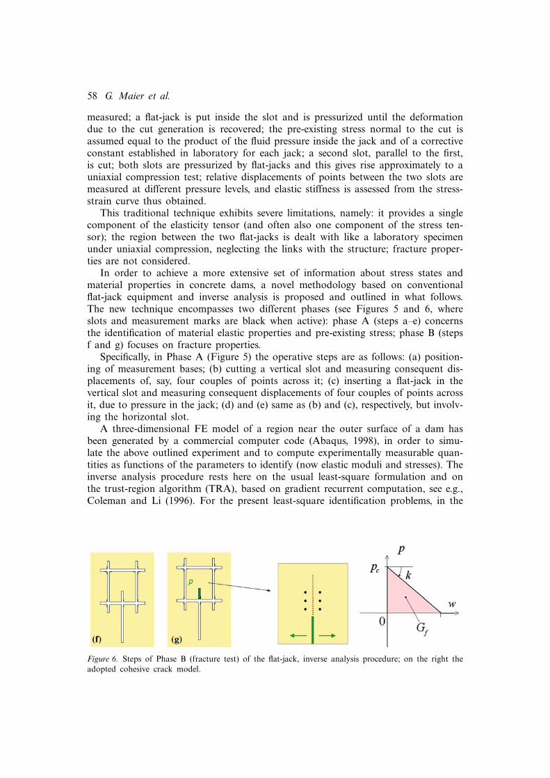
In order to achieve a more extensive set of information about stress states andmaterial properties in concrete dams, a novel methodology based on conventionalflat-jack equipment and inverse analysis is proposed and outlined in what follows.The new technique encompasses two different phases (see Figures 5 and 6, whereslots and measurement marks are black when active): phase A (steps a–e) concernsthe identification of material elastic properties and pre-existing stress; phase B (stepsf and g) focuses on fracture properties.
Specifically, in Phase A (Figure 5) the operative steps are as follows: (a) position-ing of measurement bases; (b) cutting a vertical slot and measuring consequent dis-placements of, say, four couples of points across it; (c) inserting a flat-jack in thevertical slot and measuring consequent displacements of four couples of points acrossit, due to pressure in the jack; (d) and (e) same as (b) and (c), respectively, but involv-ing the horizontal slot.
A three-dimensional FE model of a region near the outer surface of a dam hasbeen generated by a commercial computer code (Abaqus, 1998), in order to simu-late the above outlined experiment and to compute experimentally measurable quan-tities as functions of the parameters to identify (now elastic moduli and stresses). Theinverse analysis procedure rests here on the usual least-square formulation and onthe trust-region algorithm (TRA), based on gradient recurrent computation, see e.g.,Coleman and Li (1996). For the present least-square identification problems, in the
Figure 6. Steps of Phase B (fracture test) of the flat-jack, inverse analysis procedure; on the right theadopted cohesive crack model.

Inverse analyses in fracture mechanics 59
Authors’ experience, TRA turns out to be computationally preferable with respect toother first order and direct search (zero order) algorithms.
The diagnostic procedure in point leads first to the identification of Young moduliEV and EH in vertical (subscript V ) and horizontal (subscript H ) directions. In viewof the casting and compacting processes, concrete in a dam should be consideredas an orthotropic and transversally (horizontally) isotropic material, hence endowedwith five independent elastic moduli. However, in the present preliminary illustrativeexercise, only the two Young moduli are regarded as parameters to identify, by usingmeasurements in steps (c) and (e) as input for the inverse analysis. Clearly, thesemeasures are independent from the pre-existing stress state as long as the pressureis limited and the system behaves linearly; this circumstance allows to identify EV
and EH without knowing the stress. The so assessed elastic properties of the mate-rial are exploited together with the experimental data achieved from steps (b) and (d),in order to estimate the normal stresses σH and σV , pre-existing in the dam (possi-bly due to unknown expansive pathological ageing processes, such as alcali-aggregatereaction, AAR). Tangential stress τHV can be identified as well by measuring also rel-ative displacements almost tangentially to the slot, i.e., between basis marks in diag-onal directions. Clearly, plane stress hypothesis is realistic near the free surface of thedam.
An alternative set of quantities to be used as input for the inverse analysis consistsof local deformations measured by strain-gages placed near the slots. This alternativeturns out to be practically advantageous because electric signals from strain-gagescan be automatically (rather than manually) gathered, interpreted and saved on site.In both cases, i.e., measuring either relative displacements or local strains or both,numerical tests on the inverse analysis based on the TRA led so far to encouragingresults, even when random noise affects (pseudo-) experimental input data.
Phase B is based on the pressurization leading to fracture of a sort of specimengenerated by additional cuts, and on the measurement of relative displacements nearthe mouth of the crack propagation path, see Figure 6. This phase can be subdi-vided in two steps (Figure 6): (f) additional cuts are made so that a region of mate-rial becomes almost isolated from the rest of the dam and free of stresses except forthe rear zone; (g) a special flat-jack is inserted in the notch which is part of the previ-ous last vertical slot, and opening displacements are measured by a set of instrumentsalong the crack path, at different increasing pressure levels. The jack employed in thelast step (g) should be small and possibly ad hoc designed, but all the other instru-ments may be those used traditionally.
A three-dimensional FE model has been built up (see Figure 7), in order to sim-ulate the fracture process, and to compute the measurable relative displacements asfunctions of the two parameters in the adopted popular cohesive crack model shownin Figure 6. The quasi-brittle fracture model is simplified with respect to the onedealt with in Section 2, in view of the peculiar features of dam engineering situa-tions now considered. The suitability of the geometry designed for the fracture test(and visualized, together with the FE mesh, in Figure 7) has been validated by non-linear analyses resting on a continuum elastic-plastic-softening constitutive model forconcrete (Fenves model, in the computer code Abaqus, 1998): such preliminary anal-yses pointed out that only negligible plastic strains arise outside the envisaged crackpropagation plane.

60 G. Maier et al.
Figure 7. Finite element model of the proposed flat-jack test for fracture parameters identification.The zoomed picture visualizes the semicircular notch.
The identification procedure by inverse analysis exploits the measurable dataobtained in step (g), i.e., a set of opening IRD at different pressure levels. The cho-sen cohesive crack model (Figure 6) is defined by two independent parameters out ofthree (tensile strength pc, fracture energy Gf and slope k of the post-peak segment).Comparative inverse analyses have been performed for the identification first of pc
and Gf , second of pc and k, starting from the same set of input data, generated byadding to the computed pseudo-experimental data a random noise uniformly distrib-uted on a suitable range.
As a typical numerical test on the new technique, with noise in the range ±5%,identification of pc and Gf led to −2.30% error on pc and +3.80% error on Gf , theidentification of pc and k to almost the same error (−2.30%) on pc and −8.05% erroron k estimate. Such kind of results corroborates the identifiability of fracture param-eters by the proposed method (contractivity of uncertainties is observed in passingfrom input data to output estimates) and evidences the importance of a proper choiceof the parameters to identify. Figure 8a visualizes the convergence of the TRA alongthe itinerary of steps shown in Figure 8b (parameters are normalized with respect totheir ‘exact’ values). The contour plot in Figure 8b of the objective function ω on the(pc,Gf ) plane evidences that this discrepancy function turns out to be nonconvex.
In dam engineering practice the characterization of possibly deteriorated con-crete sometimes must be performed repeatedly on the same large dams. For futureroutine applications it would be desirable to mitigate the computational burden ofinverse analysis based on a large FE model, like the present one shown in Figure 7(with 138,000 degrees of freedom). Soft-computing by ANNs (see e.g.: Haykin, 1999;Waszczyszyn, 1999) may satisfy this requirement and might eventually lead to localdiagnoses carried out in situ routinely and economically.
A preliminary orientative employment of ANNs has been investigated for Phase B(fracture test) of the flat-jack technique proposed herein. The task is to estimate thetensile strength pc and the fracture energy Gf on the basis of a set of 16 experimen-tal data, namely from the relative displacements of three couples of points measuredby conventional instruments at five pressure levels.

Inverse analyses in fracture mechanics 61
Figure 8. (a) Convergence of the Trust Region algorithm for the identification of the fracture param-eters pc and Gf (solid line) and of pc and k (in dashed lines); (b) map of the discrepancy functionand iteration path to its absolute minimum.
To the above specified purpose, an ‘architecture’ 16-4-2 (16 input neurons, one hid-den layer with 4 neurons and 2 output neurons) was selected by a trial-and-errorapproach for the feed-forward, back-propagation network. The neurons in the hiddenlayer are assigned an hyperbolic tangent sigmoid as ‘transfer function’, the neuronsin the output layer a linear ‘transfer function’. In order to calibrate the 72 weightsand 6 biases of the network, the implemented ANN has been trained by 363 pat-terns (i.e., pairs of input and output vectors), generated once-for-all by direct anal-yses through the FE model in Figure 7 on the basis of equally spaced points in aselected region of the space (pc,Gf ,E). In all the training inputs perturbations havebeen added randomly extracted from a range of ±10% of the current value for theopening displacements and ±5% for the elastic modulus, with uniform probabilitydensity distribution. The training process (i.e., the minimization of the non-dimen-sional mean-square error by means of a back-propagation algorithm) was stoppedafter 600 iterations (or ‘epochs’, in the ANN jargon).
The trained network has been tested by 72 patterns generated by values of ran-domly chosen pc,Gf and E, and by the relevant measurable displacements againaffected by ±10% (±5% for E) uniformly distributed random noise. The relativeerrors of the two fracture parameters in the ANN learning and testing processes areshown in Figure 9: the neural network turns out to approximate fairly satisfacto-rily the present complex relationship, originally materialized by the large FE model(Figure 7), between the two variable vectors of the fracture parameters (and Young’smodulus E) and the relevant measurable displacements. In this illustrative example ofcomputerized in situ flat-jack fracture experiment, pre-existing stresses are assumed tobe a priori known.
A rather extensive investigation of the potentialities of ANNs in local diagnosticanalyses of concrete dams can be found in Fedele et al. (2005) with reference to dila-tometric tests in parallel deep holes drilled in the dam. This novel technique com-bines inverse analysis with experiments which are traditional in rock mechanics (seee.g., Goodman, 1980). The dilatometric test is complementary, clearly not alternative,

62 G. Maier et al.
Figure 9. Relative errors of two fracture parameters identified by a neural network, with 363 learningand 72 testing patterns.
to the flat-jack procedure discussed in what precedes. Such dilatometric diagnosticmethod was partly anticipated by the ‘pressure tunnel’ studied in Gioda and Maier(1980) and has recently been extended to fracture mechanics, Maier et al. (2004).
4. Indentation, imprint mapping and inverse analysis combined in micro-technologies
A spreading methodology for mechanical characterisation of materials at the micro-and nano-scales is based on indentation tests. Fracture processes in quasi-brittlematerials and delamination in film-substrate systems are easily induced in a non-destructive manner by, e.g., pyramidal (Vickers) or conical (Rockwell) indenters, andcan effectively be simulated using interface and cohesive crack models to parameteridentification purposes.
4.1. Fracture models and test
The cohesive model adopted in what follows was originally proposed for mode Ifracture by Rose et al. (1981) for metals and for bimetallic interfaces, then it wasextended to two- and three-dimensional mixed-mode fracture by Xu and Needleman(1994), Camacho and Ortiz (1996), Ortiz and Pandolfi (1999). Its formulation is cen-tred on the following ‘potential function’:
φ (δ)= epcδc
(1−
(1+ δ
δc
)exp
(− δ
δc
))(8a)
where: δ =√
β2(w2
t1 +w2t2
)+w2n (8b)
In the above formulae, e is Neper number (basis of natural logarithms), pc indi-cates the maximum cohesive normal traction and δc represents a characteristic open-ing displacement. It can be easily shown that the quantity which, in this model,plays the role of mode I fracture energy is GF =epcδc. Equation (8b) defines δ as aneffective displacement discontinuity across the interface, β being a parameter whichquantifies different weights for sliding (wt1 and wt2) with respect to opening (wn)displacements. The non-holonomic behaviour in this interface model is governed bythe maximum attained effective displacement jump δmax, which represents the only

Inverse analyses in fracture mechanics 63
Figure 10. Interface model for mode I (a) and mode II (b) fracture, the latter for β =0.8.
internal variable in the model. The relationship which describes the evolution of thisvariable reads:
δmax ={
δ if δ = δmax and δ ≥00 otherwise
(9)
Cohesive tractions under progressive fracture (i.e., for increasing δmax) or along alinear path back to the origin in case of unloading, are defined as follows:
{pn
pti
}={
∂φ/∂wn
∂φ/∂wti
}
= epc
δc
exp(
− δ
δc
){wn
β2wti
}if δ = δmax and δ ≥0
(i =1,2){pn
pti
}= e
pc
δc
exp(
−δmax
δc
){wn
β2wti
}if δ = δmax or δ <0
(10)
In mode I fracture, see Figure 10a, under progressive opening (δ = wn > 0; δ =wn > 0), the response of the interface is characterised by a tensile stress which firstincreases up to its maximum value pc and then decreases asymptotically to zero in asoftening regime. Non-holonomic behaviour and damage are exhibited when unload-ing occurs (wn <0) starting from wn = δmax. Figure 10b visualises the modelled inter-face behaviour in the case of mode II fracture.
The parameters to identify in the interface model, Equations (8)–(10), are pc, δc
and β. In the FE discretisation adopted for the present illustrative examples (seeFigure 11) the above interface model is employed where fracture is expected, namelyeither along the surface between film and substrate (see Figure 11a) or over theplanes which are orthogonal to the upper face of the specimen through the diago-nals of the pyramidal (Vickers) indenter (Figure 11b).
Like in previous simulations of indentation tests (Bhattacharya and Nix, 1998;Jayaraman et al., 1998; Cheng and Cheng, 1999), the commercial code Abaqus(1998) is employed with its large plastic strain capability. The contact interfacebetween the indenter and the specimen is characterised by Coulomb friction withoutdilatancy, i.e., by a non-associative rigid-plastic model.
Boundary conditions are consistent with geometrical and physical symmetries:two-dimensional axial-symmetry for conical indentations of isotropic solids; symme-tries in Vickers indentation of isotropic materials allow to reduce the domain, e.g.,

64 G. Maier et al.
Figure 11. Finite element meshes adopted for simulation of: (a) Rockwell indentation of isotropiccoating and substrate; (b) Vickers indentation of brittle bulk specimen.
Figure 12. Experimental results on Zirconia specimen: (a) indentation curve; (b) imprint mapping byatomic force microscope and (c) crack visualization by optical microscopy.
to one quarter (Figure 11). The computing effort is further considerably reduced bypreliminarily performing the condensation of the degrees-of-freedom belonging to thespecimen portion exterior to the domain where all inelastic phenomena are a priorireasonably expected to be confined.
In both examples (a) and (b) in Figure 11, the indentation process is subdividedinto M steps, run by index i =1. . .M, and at each step the imposed force Fmi and thecorresponding penetration depth of the indenter ucur
mi are recorded, see the indenta-tion curves in Figure 12a. Imprint displacement u
imp
mj normal to the indented surface(see Figure 12b) are measured in N selected points, run by index j . Typical instru-ments suitable to these measurements are AFMs at the micro-scale, laser profilome-ters at the macro-scale. In the case of Vickers indentation of brittle materials, Figures11b and 12c, the crack length lcram as well can be measured on the specimen surface.
The discrepancy function to be minimised encompasses, in the more general case,three kinds of contributions, namely:
ω (x)= 1M
M∑
i=1
(ucur
ci (x)−ucurmi
ucurmax
)2
+ 1N
N∑
j=1
(u
imp
cj (x)−uimp
mj
uimpmax
)2
+(
lcrac (x)− lcram
lcramax
)2
(11)
where vector x collects the parameters pc, δc and β to identify; subscript m
marks experimentally measured quantities; subscript c indicates computed measurable

Inverse analyses in fracture mechanics 65
quantities. Displacements are normalised by the relevant maximum values (i.e., byucur
max, uimpmax and dcra
max, respectively).Equal ‘weights’ for all the contributions to the discrepancy norm (11) are assumed
in the present illustrative exercises, carried out using computer-generated pseudo-experimental data; weights related to the measurement errors should be introducedwhen real experimental data are employed.
The dependence of the computed quantities on the material parameters is implicitin the FE model. Due to both geometrical (finite strains) and material nonlineari-ties allowed for, the objective function ω is non-explicit and expected to be generallynon-convex. Like in Section 2, a conventional deterministic, batch (non-sequential)approach is adopted here for parameter identification, and the Trust Region algo-rithm (TRA) is employed once again as a tool for minimum search.
4.2. Inverse analysis of brittle materials fracture
Fracture processes induced by Vickers indentation in brittle materials are being stud-ied, both from an experimental and numerical point of view, on Zirconia specimens.Micro indentation tests up to 1N load (see Figures 12a and b) and macro indenta-tion tests up to 1kN load (see Figure 12c) have been performed. Figures 12b and cvisualise typical images of the imprint after indentation; in the latter cracks are seento develop in correspondence of the four corners of the Vickers indenter. Cracks turnout to open during the unloading indentation phase.
The test simulation has been carried out by employing associative Drucker–Pragermodel with linear isotropic hardening, and the above specified interface model.
Figure 13a shows the contour map of the computed displacements, orthogonal tothe plane along which interface elements have been inserted, i.e., it visualises a ‘half-penny crack’ shape, which resembles that obtained experimentally.
Preliminary inverse analysis exercises, based on indentation of brittle materials,have been carried out by exploiting pseudo-experimental information in terms ofindentation curve, imprint geometry and crack length, in order to identify the fol-lowing material parameters: Young modulus E, compressive yield stress pcc, hard-ening modulus Hpl (relating linearly the instantaneous elastic limit to the equivalent
Figure 13. Half-penny shape crack in the computed imprint due to Vickers indentation: (a) contourmap of displacements orthogonal to the plane along which interface elements have been inserted; (b)deformed mesh.
66 G. Maier et al.
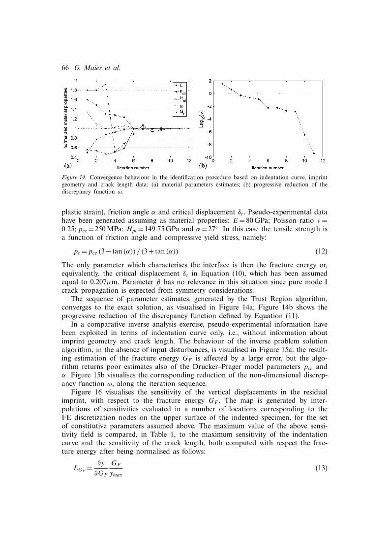
Figure 14. Convergence behaviour in the identification procedure based on indentation curve, imprintgeometry and crack length data: (a) material parameters estimates; (b) progressive reduction of thediscrepancy function ω.
plastic strain), friction angle α and critical displacement δc. Pseudo-experimental datahave been generated assuming as material properties: E = 80 GPa; Poisson ratio ν =0.25;pcc =250 MPa; Hpl =149.75 GPa and α =27◦. In this case the tensile strength isa function of friction angle and compressive yield stress, namely:
pc =pcc (3− tan (α)) / (3+ tan (α)) (12)
The only parameter which characterises the interface is then the fracture energy or,equivalently, the critical displacement δc in Equation (10), which has been assumedequal to 0.207µm. Parameter β has no relevance in this situation since pure mode Icrack propagation is expected from symmetry considerations.
The sequence of parameter estimates, generated by the Trust Region algorithm,converges to the exact solution, as visualised in Figure 14a; Figure 14b shows theprogressive reduction of the discrepancy function defined by Equation (11).
In a comparative inverse analysis exercise, pseudo-experimental information havebeen exploited in terms of indentation curve only, i.e., without information aboutimprint geometry and crack length. The behaviour of the inverse problem solutionalgorithm, in the absence of input disturbances, is visualised in Figure 15a: the result-ing estimation of the fracture energy GF is affected by a large error, but the algo-rithm returns poor estimates also of the Drucker–Prager model parameters pcc andα. Figure 15b visualises the corresponding reduction of the non-dimensional discrep-ancy function ω, along the iteration sequence.
Figure 16 visualises the sensitivity of the vertical displacements in the residualimprint, with respect to the fracture energy GF . The map is generated by inter-polations of sensitivities evaluated in a number of locations corresponding to theFE discretization nodes on the upper surface of the indented specimen, for the setof constitutive parameters assumed above. The maximum value of the above sensi-tivity field is compared, in Table 1, to the maximum sensitivity of the indentationcurve and the sensitivity of the crack length, both computed with respect the frac-ture energy after being normalised as follows:
LGF= ∂y
∂GF
GF
ymax
(13)

Inverse analyses in fracture mechanics 67
Figure 15. Convergence behaviour in the identification procedure based on indentation curve only: (a)material parameters estimates; (b) progressive reduction of the discrepancy function ω.
Figure 16. Sensitivity of the imprint geometry with respect to the fracture energy parameter GF .
Table 1. Comparison among the maximum sensitivities ofindentation curve, imprint geometry and crack length, respec-tively, with respect to fracture energy parameter GF .
y max[LGF
]
ucurcj 0.0019
uimp
cj 0.0054lcrac 0.025
The derivatives with respect to GF are evaluated taking as their argument the‘exact’ parameters, originally adopted for computing the pseudo-experimental data.In the numerical computations, derivatives have been approximated by 1st-order for-ward finite-differences with 0.01% increment. Among the three kinds of availableexperimental data, namely indentation curve, imprint geometry and crack length, thelargest sensitivity with respect to the fracture energy parameter (account taken of the

68 G. Maier et al.
different scales for the three variables) is exhibited by the crack length. Therefore, asqualitatively expected, crack length represents a crucial experimental information tobe exploited in order to identify the material parameter GF .
The above results on sensitivities are consistent with the already observed con-vergence difficulties in the identification process of the fracture energy and of otherparameters, see Figure 15, when the only experimental data inserted into the inverseanalysis procedure is the indentation curve. The main conclusion arising from thenumerical tests on sensitivity, outlined in what precedes, is a confirmation that mea-surements on the residual deformed configuration of the specimen (namely imprintgeometry and crack length) are generally bound to enhance the identification ofmaterial parameters through indentation tests.
4.3. Inverse analysis of coating-substrate delamination
When Rockwell indention is performed on a film-substrate system, two differentdelamination mechanisms are expected, depending on the ratio between the yieldstrengths of coating and substrate (see, e.g.: Abdul-Baqi and Van der Giessen, 2001;Li and Siegmund, 2004). In the case of ductile film on elastic substrate (e.g., goldon silicium), delamination phenomena are observed during the loading phase ofthe indentation process. Such phenomena materialise as mode II dominant fracture,caused by plastic flow in the film: the coating material spreads in horizontal direc-tion due to the elastic substrate, see Figure 17a. The main effect on the indentationcurves is a decrease of the applied force at equal penetration depth. As for a hardfilm on a ductile substrate, delamination usually occurs in mode I during unloading,due to the different recovery of elastic deformations between the hard film and theductile substrate, see Figure 17b.
The inverse analysis exercise outlined below concerns a ductile film, modelled aselastic perfectly-plastic Huber-Mises material, on an elastic substrate. The parame-ters to identify in the adopted interface model, Equations (8)–(10), are pc, δc andβ. Pseudo-experimental information are exploited, generated through direct analy-sis by assuming the following parameter set (subscript f and s indicate film and
Figure 17. Delamination displacement fields due to indentation: (a) horizontal displacements in a caseof ductile film on elastic substrate; (b) vertical displacements in a case of hard film on ductilesubstrate.

Inverse analyses in fracture mechanics 69
Figure 18. Convergence of Trust Region algorithm in the identification procedure based on bothindentation curves and imprint geometry data: (a) normalised estimates of the parameters govern-ing the delamination of a ductile film from a substrate; (b) progressive reduction of the discrepancyfunction ω.
substrate, respectively): Ef = 80 GPa, νf = 0.4, σyf = 200 MPa, Es = 200 GPa, νs =0.3;pc =100 MPa, δc =0.002µm, β =0.8.
The solution process of the inverse problem implies once again the minimisa-tion of the discrepancy function ω(x) according to Equation (11), but without thelast addend. The Trust region algorithm converges toward the optimal estimates asshown in Figure 18a. In the absence of input disturbances, the maximum error inthe identification of δc amounts to 19% difference with respect to the exact value.The progressive reduction of the non-dimensional discrepancy function ω along theiteration sequence and its stabilisation around a minimum value is visualised in Fig-ure 18b. Significant residual errors in the parameter estimates are noticed as expected,since the vertical displacements of material points are little affected by the delamina-tion process, i.e., are not quite sensitive to the sought parameters. If the input of theinverse analysis procedure could include horizontal residual displacements, the soughtparameters (and those in the interface model among them) would probably becomeeasily and efficiently identifiable by the methodology presented in this paper. But sucha prospect requires future developments of the experimental mechanics implicationsof the present methodology.
5. Conclusions
In what precedes inverse analyses in fracture mechanics have been reviewed andbriefly discussed with reference to specific but representative topics investigated bythe authors’ team, and with the following further limitations: quasi-brittle fractureof cementitious materials and delamination along coating-substrate interfaces; quasi-static (not dynamic) external actions; emphasis on recent or current methodologicaldevelopments and their motivation and potential usefulness, even if not all corrobo-rated by practical applications; mainly deterministic batch identification techniques.
In general terms, it can be said nowadays that the EKF methodology and its recentdevelopments, if combined with a suitable mathematical model of the experimentaltests, represent powerful and reliable tools in different application fields, which notonly identify meaningful material parameters but also provide quantitative assessment

70 G. Maier et al.
of their uncertainties to structural analyses purposes in engineering practice, see e.g.,Bittanti et al. (1984), Bolzon et al. (2002), Nakamura et al. (2003), Corigliano andMariani (2004). However, even traditional least-square deterministic approaches to cal-ibration of simple cohesive crack models lead to still challenging mathematical andnumerical problems such as MPEC, briefly considered in what precedes.
The specific issues considered in this paper require and deserve further interdis-ciplinary investigations from various standpoints, particularly as for computationalproblems and experimental equipment. The consequences of systematic (non stochas-tic) modeling errors in test simulations on the resulting estimates of material parame-ters, should attract more and more attention in future researches. Desirable are futureextensions of the inverse analysis methodology to mixed-mode fracture models and torecently developed methods of modeling smooth transitions from diffused damage tostrain localization and to crack as displacement discontinuity. Of course, other areasof fracture mechanics, in primis ductile and dynamic fracture, give rise to interestinginverse analysis problems.
Despite the above limitations, even a small sample of engineering-motivated recentresearch results of fracture parameter identifications can evidence the remarkablepotentialities of inverse analysis of fracture processes, combined with experimenta-tion, in diverse mechanical technologies.
Acknowledgements
The research results referred to in this paper have been achieved in two projects (onconcrete dams and on inverse analyses) co-financed by the Italian University Minis-try (MIUR). Thanks are expressed to former student M. Lettieri for his contributionto Section 3.
References
ABAQUS/Standard (1998). Theory and User’s Manuals. Release 6.2-1, Pawtucket, RI (USA).Abdul-Baqi, A. and Van der Giessen, E. (2001). Indentation-induced interface delamination of a strong
film on a ductile substrate. Thin Solid Films 381, 143–154.Abdul-Baqi, A. and Van der Giessen, E. (2002). Numerical analysis of indentation-induced cracking of
brittle coatings on ductile substrates. International Journal of Solids and Structures 39, 1427–1442.Alvaredo, A.M. and Torrent, R.J. (1987). The effect of the shape of the strain-softening diagram on the
bearing capacity of concrete beams. Materials and Structures 20, 448–454.Ardito, R., Bartolotta, L., Ceriani, L. and Maier, G. (2004). Diagnostic inverse analysis of concrete dams
with static excitation. Journal of the Mechanical Behavior of Materials 15(6), 381–389.Barenblatt, G.I. (1962). The mathematical theory of equilibrium cracks in brittle fracture. Advances in
Applied Mechanics 7, 55–129.Bazant, Z.P. and Planas, J. (1998). Fracture and Size Effect in Concrete and Other Quasi-brittle Materials,
CRC Press: Boca Raton, FL (USA).Bhattacharya, A.K. and Nix W.D. (1998). Finite element simulation of indentation experiments. Inter-
national Journal of Solids and Structures 24, 881–891.Bittanti, S., Maier, G. and Nappi, A. (1984). Inverse problems in structural elasto-plasticity: a Kalman
filter approach. In: A. Sawczuck and G. Bianchi (eds.) Plasticity Today Elsevier Applied Science,London, pp. 311–329.
Bocciarelli, M., Bolzon, G. and Maier, G. (2005). Parameter identification in anisotropic elastoplasticityby indentation and imprint mapping. Mechanics of Materials 37, 855–868.

Inverse analyses in fracture mechanics 71
Bolzon, G. and Cocchetti, G. (2003). Direct assessment of structural resistance against pressurized frac-ture. International Journal for Numerical and Analytical Methods in Geomechanics 27, 353–378.
Bolzon, G., Cocchetti, G., Maier, G., Novati, G. and Giuseppetti, G. (1994a). Boundary element and finiteelement fracture analysis of dams by the cohesive crack model: a comparative study. In: E. Bourdarot,J. Mazars and V. Sauma (eds.) Dam Fracture and Damage Balkema, Rotterdam, pp. 69–78.
Bolzon, G. and Corigliano, A. (1997a). A discrete formulation for elastic solids with damaging interfaces.Computer Methods in Applied Mechanics and Engineering 140, 329–359.
Bolzon, G., Fedele, R. and Maier, G. (2002). Identification of cohesive crack models by Kalman filter.Computer Methods in Applied Mechanics and Engineering 191, 2847–2871.
Bolzon, G., Ghilotti, D. and Maier, G. (1997b). Parameter identification of the cohesive crack model,In: H. Sol and C.W.J. Oomens (eds.) Material Identification Using Mixed Numerical ExperimentalMethods Kluwer Academic Publisher, Dordrecht, pp. 213–222.
Bolzon, G. (1996). Hybrid finite element approach to quasi-brittle fracture. Computer and Structures 60,733–741.
Bolzon, G. and Maier, G. (1998). Identification of cohesive crack models for concrete by three-pointbending tests, In: R. de Borst, N. Bicanic, H. Mang and G. Meschke (eds.) Computational Model-ling of Concrete Structures Balkema Publishers, Rotterdam, pp. 301–310.
Bolzon, G., Maier, G. and Novati, G. (1994b). Some aspects of quasi-brittle fracture analysis as a linearcomplementarity problem, In: Z.P. Bazant, Z. Bittnar, M. Jirasek and J. Mazars (eds.) Fracture andDamage in Quasi-brittle Structures E and FN Spon, London, pp. 159–174.
Bolzon, G., Maier, G. and Panico, M. (2004). Material model calibration by indentation, imprint map-ping and inverse analysis. International Journal of Solids and Structures 41, 2957–2975.
Bolzon, G., Maier, G. and Tin-Loi, F. (1995). Holonomic and non-holonomic simulations of quasi-brittlefracture:a comparative study of mathematical programming approaches, In: F.H. Wittman (ed.) Frac-ture Mechanics of Concrete Structures Aedificatio Publishers, Freiburg, pp. 885–898.
Bolzon, G., Maier, G. and Tin-Loi, F. (1997c). On multiplicity of solutions in quasi-brittle fracture com-putations. Computational Mechanics 19, 511–516.
Bruhwiler, E. and Wittmann, F.H. (1990). Wedge-splitting test, a new method of performing stable frac-ture mechanics tests. Engineering Fracture Mechanics 35, 117–125.
Bui, H.D. (1994). Inverse Problems in the Mechanics of Materials: an Introduction, CRC Press, BocaRaton, FL (USA).
Camacho, G.T. and Ortiz, M. (1996). Computational modelling of impact damage in brittle materials.International Journal of Solids and Structures 33, 2899–2938.
Carpinteri, A. (1989). Softening and snap-back instability of cohesive solids. International Journal forNumerical Methods in Engineering 29, 1521–1538.
Carpinteri, A., Chiaia, B. and Invernizzi, S. (2001). Numerical analysis of indentation fracture in quasi-brittle materials. Engineering Fracture Mechanics 71, 567–577.
CEB-FIP Model Code 1990 (1993). Design Code, Thomas Telford Ltd., London.Cen, Z. and Maier, G. (1992). Bifurcations and instabilities in fracture of cohesive-softening structures: a
boundary element analysis. Fatigue and Fracture of Engineering Materials and Structures 15, 911–928.Cetinel, H., Uyulgan, B., Tekmen, C., Ozdemir, I. and Celik, E. (2003). Wear properties of functionally
gradient layers on stainless steel substrates for high temperature applications. Surface and CoatingsEngineering 174–175, 1089–1094.
Cheng, Y.T. and Cheng, C.M. (1999). Scaling relationships in conical indentation of elastic perfectly-plastic solids. International Journal of Solids and Structures 36, 1231–1243.
Cocchetti, G. and Maier, G. (2003). Elastic-plastic and limit-state analyses of frames with softening plas-tic-hinge models by mathematical programming. International Journal of Solids and Structures 40,7219–7244.
Cocchetti, G., Maier, G. and Shen, X. (2002). Piecewise-linear models for interfaces and mixed modecohesive cracks. Computer Methods in Engineering and Science 3, 279–298.
Coleman, T.F. and Li, Y. (1996). An interior trust region approach for nonlinear minimisation subjectto bounds. SIAM Journal on Optimization 6, 418–445.
Comi, C., Maier, G. and Perego, U. (1992). Generalized variable finite element modeling and extremumtheorems in stepwise holonomic elastoplasticity with internal variables. Computer Methods in AppliedMechanics and Engineering 96, 213–237.

72 G. Maier et al.
Corigliano, A. and Mariani, S. (2004). Parameter identification in explicit structural dynamics: perfor-mance of the extended Kalman filter. Computer Methods in Applied Mechanics and Engineering 193,3807–3835.
Cottle, R.W., Pang, J.S. and Stone, R.E. (1992). The Linear Complementarity Problem, Academic Press,Boston.
Denarie, E., Saouma, V., Iocco, A. and Varelas, D. (2001). Concrete fracture process zone characteriza-tion with fiber optics. ASCE Journal of Engineering Mechanics 127, 494–502.
Dirkse, S.P. and Ferris, M.C. (1995). The PATH solver: a non-monotone stabilization scheme for mixedcomplementarity problems. Optimization Methods and Software 5, 123–156.
Elices, M., Guinea, G.V. and Planas, J. (1992). Measurement of the fracture energy using three-pointbend tests: Part 3 – Influence of cutting the P-δ tail. Materials and Structures 25, 327–334.
Facchinei, F. and Pang, J.S. (2003). Finite-Dimensional Variational Inequalities and Complementarity Prob-lems, Vol. II, Springer Series in Operations Research and Financial Engineering, Berlin.
Fedele, R., Maier, G. and Miller, B. (2005). Identification of elastic stiffness and local stresses in concretedams by in situ tests and neural networks. Structure and Infrastructure Engineering 1(3), 165–180.
Fiacco, A.V., McCormick and G.P. (1968). Nonlinear Programming: Sequential Unconstrained Minimiza-tion Techniques, Wiley, New York (reprinted by SIAM Publications, Philadelphia, 1990).
Frangi, A. and Maier, G. (2002). The symmetric Galerkin boundary element method in linear and non-linear fracture mechanics, In: D. Beskos and G. Maier (eds.) Boundary Element Advances in SolidMechanics CISM Lecture Notes, Vol. 440, Springer Verlag, Wien.
Gioda, G. and Maier, G. (1980). Direct search solution of an inverse problem in elastoplasticity: iden-tification of cohesion, friction angle and in situ stress by pressure tunnel tests. International Journalfor Numerical Methods in Engineering 15, 1823–1848.
Goodman, R.E. (1980). Introduction to Rock Mechanics, John Wiley and Sons, New York.Guinea, G.V., Planas, J. and Elices, M. (1992). Measurement of the fracture energy using three-point
bend tests: Part 1 – Influence of experimental procedures. Materials and Structures 25, 212–218.Guinea, G.V., Planas, J. and Elices, M. (1994). A general bilinear fit for the softening curve of concrete.
Materials and Structures 27, 99–105.Haykin, S. (1999). Neural Networks. A Comprehensive Foundation, 2nd Edition, Prentice Hall, Upper
Saddle River, NJ (USA).Hillerborg, A. (1991). Application of the fictitious crack model to different types of materials. Interna-
tional Journal of Fracture 51, 95–102.Jayaraman, S., Hahn, G.T., Oliver, W.C., Rubin, C.A. and Bastias, P.C. (1998). Determination of mono-
tonic stress-strain curve of hard materials from ultra-low-load indentation tests. International Journalof Solids and Structures 35, 365–381.
Jirasek, M. and Bazant, Z.P. (2001). Inelastic Analysis of Structures, John Wiley and Sons, New York.Karihaloo, B. (1995). Fracture Mechanics and Structural Concrete, Longman Scientific and Technical,
Burnt Mill, Harlow.Kleiber, M., Antunez, H., Hien, T.D. and Kowalczyk, P. (1997). Parameter Sensitivity in Nonlinear
Mechanics. Theory and Finite Element Computations, John Wiley and Sons, New York.Li, W. and Siegmund, T. (2004). An analysis of the indentation test to determine the interface toughness
in a weakly bonded thin film coating-substrate system. Acta Materialia 52, 2989–2999.Luo, Z.Q., Pang, J.S. and Ralph, D. (1996). Mathematical Programs with Equilibrium Constraints,
Cambridge University Press, Cambridge (UK).Maier, G. (1968). On softening flexural behaviour of beams in elasto-plasticity. Rendiconti dell’Istituto
Lombardo di Scienze e Lettere 102, 648–677, (in Italian).Maier, G. (1970). A matrix structural theory of piecewise-linear plasticity with interacting yield planes.
Meccanica 5, 55–66.Maier, G., Ardito, R. and Fedele, R. (2004). Inverse analysis problems in structural engineering of con-
crete dams. In: Z.H. Yao, M.W. Yuan e and W.X. Zhong (eds.) Computational Mechanics TsinghuaUniversity Press & Springer-Verlag, Beijing, pp. 97–107.
Maier, G. and Comi, C. (2000). Energy properties of solutions to quasi-brittle fracture mechanics prob-lems with piecewise linear cohesive crack models, In: A. Benallal (ed.) Continuous Damage and Frac-ture Elsevier, Amsterdam, pp. 197–205.

Inverse analyses in fracture mechanics 73
Maier, G., Giannessi, F. and Nappi, A. (1982). Identification of yield limits by mathematical program-ming. Engineering Structures 4, 86–98.
Maier, G., Novati, G. and Cen, Z. (1993). Symmetric Galerkin boundary element method for quasi-brittle fracture and frictional contact problems. Computational Mechanics 13, 74–89.
Mroz, Z. and Stavroulakis, G.E. (eds.) (2005). Identification of Materials and Structures, CISM LectureNotes, Vol. 469, Springer-Verlag, Wien.
Nakamura, T., Yu, G., Prchlik, L., Sampath, S. and Wallace, J. (2003). Micro-indentation and inverseanalysis to characterize elastic-plastic graded materials. Materials Science and Engineering A 345,223–233.
Nash, J.F. (1951). Non-cooperative games. Annals of Mathematics 54, 286–295.Norgaard, M., Pulsen, N. and Ravn, O. (2000). New developments in state estimation for nonlinear sys-
tems. Automatica 36, 1627–1638.Ohring, M. (1991). The Materials Science of Thin Films, Academic Press, New York.Ortiz, M. and Pandolfi, A. (1999). Finite-deformation irreversible cohesive elements for three-dimensional
crack-propagation analysis. International Journal for Numerical Methods in Engineering 44, 1267–1282.
Pang, J.S. and Tin-Loi, F. (2001). A penalty interior point algorithm for a parameter identification prob-lem in elasto-plasticity. Mechanics of Structures and Machines 29, 85–99.
Planas, J., Elices, M. and Guinea, G.V. (1992). Measurement of the fracture energy using three-pointbend tests: Part 2-Influence of bulk energy dissipation. Materials and Structures 25, 305–312.
RILEM Draft Recommendation (1985). Determination of the fracture energy of mortar and concreteby means of three-point bend tests on notched beams. Materials and Structures 18, 285–290.
Rose, J.H., Ferrante, J. and Smith, J.R. (1981). Universal binding energy curves for metals and bimetallicinterfaces. Physical Review 9, 675–678.
Spearing, S.M. (2000). Materials issues in microelectromechanical systems (MEMS). Acta Materialia 48,179–196.
Stavroulakis, G.E. (2000). Inverse and Crack Identification Problems in Engineering Mechanics, KluwerAcademic Publishers, Durtrecht.
Stavroulakis, G.E., Bolzon, G., Waszczyszyn, Z. and Ziemanski, L. (2003). Inverse Analysis, In:B. Karihaloo, R.O. Ritchie and I. Milne (eds.) Comprehensive Structural Integrity Vol. 3, ElsevierScience, Oxford.
Tin-Loi, F. and Que, N.S. (2001a). Parameter identification of quasi-brittle materials as a mathematicalprogram with equilibrium constraints. Computer Methods in Applied Mechanics and Engineering 190,5819–5836.
Tin-Loi, F. and Que, N.S. (2002a). Identification of cohesive crack fracture parameters by evolutionarysearch. Computer Methods in Applied Mechanics and Engineering 191, 5741–5760.
Tin-Loi, F. and Que, N.S. (2002b). Nonlinear programming approaches for an inverse problem in quasi-brittle fracture. International Journal of Mechanical Sciences 44, 843–858.
Tin-Loi, F. and Xia, S.H. (2001b). Non-holonomic elastoplastic analysis involving unilateral frictionlesscontact as a mixed complementarity problem. Computer Methods in Applied Mechanics and Engineer-ing 190, 4551–4568.
Volinsky, A.A., Moody N.R. and Gerberich, W.W. (2002). Interfacial toughness measurement for thinfilm on substrates. Acta Materialia 50, 441–466.
Waszczyszyn, Z. (ed.) (1999). Neural Networks in the Analysis and Design of Structures, CISM LecturesNotes, Vol. 404, Springer Verlag, Wien.
Wittmann, F.H. and Hu, X. (1991). Fracture process zone in cementitious materials. International Journalof Fracture 51, 3–18.
Xiaodong, L., Dongfeng, D. and Bhushan, B. (1997). Fracture mechanisms of thin amorphous carbonfilms in nano-indentation. Acta Materialia 45, 4453–4461.
Xu, X.P. and Needleman, A. (1994). Numerical simulation of fast crack growth in brittle solids. Journalof the Mechanics and Physics of Solids 42, 1397–1434.
Zhi-He, J., Glaucio, H., Paulino, R.H. and Dodds, J. (2003). Cohesive fracture modeling of elastic–plasticcrack growth in functionally graded materials. Engineering Fracture Mechanics 70, 1885–1912.