inverter generator… · 2016-09-21 · dc socket 17. dc circuit breaker reset 18. engine switch...
TRANSCRIPT

KNOW YOUR PRODUCT
WARNING: Read all safety warnings and all instructions. Failure to follow the warnings and instructions may result in electric shock, fire and/or serious injury. Save all warnings and instructions for future reference.
1215
INVERTERGENERATOR•2200WMAX.POWER•KEYSTARTWITHREMOTE•2X240V15APOWEROUTLETS•USBPORT•SMARTTHROTTLETECHNOLOGY
INSTRUCTIONMANUAL

2
ENGINE
Motor Type: 4-stroke, OHV, 1-cylinder
Displacement: 125cc
Engine Speed: 5000/min-1(ECON switch
is off)
Ignition System: T.D.I
Oil Capacity: 450ml
Fuel Tank Capacity: 7 litres
Fuel Type: 91 RON Unleaded Petrol
Spark Plug: Torch A7RTC
Fuse: 20 Amp
Battery Type: Sealed Lead Acid (SLA)
12 Volt, 6Ah
Battery Part No.: MFQ-6L or equivalent
Noise Level Rating (7m): 65dB
SPECIFICATIONS - MODEL NO. FBT-3100
KNOW YOUR PRODUCT
1. Fuel cap2. Fuel cap lever3. Spark plug socket4. Control panel5. Recoil starter6. Fuel valve 7. Rear maintenance cover8. Top maintenance cover 9. AC sockets10. Oil Fill bottle11. Overload indicator LED12. Power indicator LED13. Oil alert indicator LED14. Battery power LED15. Econ throttle switch16. DC socket
17. DC circuit breaker reset18. Engine switch19. Emergency stop button20. USB port21. Keys and remote22. Convertible screwdriver23. Charging cable and clamp set24. Oil drain tube25. Fuse (spare)26. Retractable handle27. Wheels28. Primer bulb29. Battery charging socket30. Grounding terminal31. Battery access cover32. Remote switch
GENERATOR
AC Output: 240V
50Hz
15Amp
2000W
2200W Max.
DC output: 12V, 8.3Amp
USB output: 5V, 5W, 1Amp
L x W x H: 545 x 290 x 500mm
Weight: 28kg

REMOTE CONTROL
12V DC 8.3A
12 V APPLIANCE OUTLET 8.3A
5V DC USB
BATTERY POWER
OVERLOAD RUN LOW OIL
STOP
ECONOMYON
ONOFF
240V
OFF
STOP
START
ONDC OVERLOAD
RESET
REMOTE CONTROL
12V DC 8.3A
12 V APPLIANCE OUTLET 8.3A
5V DC USB
BATTERY POWER
OVERLOAD RUN LOW OIL
STOP
ECONOMYON
ONOFF
240V
OFF
STOP
START
ONDC OVERLOAD
RESET
REMOTE CONTROL
12V DC 8.3A
12 V APPLIANCE OUTLET 8.3A
5V DC USB
BATTERY POWER
OVERLOAD RUN LOW OIL
STOP
ECONOMYON
ONOFF
240V
OFF
STOP
START
ONDC OVERLOAD
RESET
4
3
KNOW YOUR PRODUCT (cont.)
10
182917
1126
21
22 23 27
24
12 13 20 14 15 1916
1
3 56 2528 7
1 2
8
9
Rear Front
31
32
30

4
TABLE OF CONTENTS
SPECIFICATIONS....................................................... Page 02
KNOW YOUR PRODUCT........................................... Page 02
INTRODUCTION........................................................ Page 05
SAFETY INSTRUCTIONS........................................... Page 05
EXPLANATION OF RISKS ......................................... Page 08
PRE-OPERATION CHECK.......................................... Page 12
OPERATION............................................................... Page 15
MAINTENANCE......................................................... Page 24
TRANSPORTING & STORAGE .................................. Page 29
TROUBLE SHOOTING .............................................. Page 30
DESCRIPTION OF SYMBOLS..................................... Page 31
CONTENTS................................................................ Page 32
WARRANTY................................................................ Page 34

5
Congratulations on purchasing a Full Boar Digital Inverter Generator. Your Full Boar Digital Inverter Generator FBT-3100 has been designed to give regulated electricity for a continuous, uninterrupted power supply. Inverter technology provides a suitable power source for camping applications, outdoor lights, sound systems, televisions, microwaves and power tools.Read and understand the Instruction Manual before operating the generator. Failure to do so could result in personal injury or equipment damage.
INTRODUCTION
WARNING! When using this equipment, basic safety precautions, including the following, should always be followed to reduce risk of fire, electric shock, personal injury and material damage.
SAFETY INSTRUCTIONS
ELECTRICAL SAFETY
Read and understand the manual prior to operating this tool.
Save these instructions and other documents supplied with this tool for future reference.
The petrol generator has been designed to output 240V only. Always check that the power supply corresponds to the voltage on the rating plate.
Note: The supply of 230V and 240V on Full Boar tools are interchangeable for Australia and New Zealand.
Using an Extension Lead
Always use an approved extension lead suitable for the power output from this generator. Before use, inspect the extension lead for signs of damage, wear and ageing. Replace the extension lead if damaged or defective. When using an extension lead on a reel, always unwind the lead completely. Use of an extension lead not suitable for the power input of the tool or which is damaged or defective may result in a risk of fire and electric shock.

6
• The generator is designed to give safe and dependable service if operated according to instructions.
• Read and understand the Owner’s Manual before operating the generator. Failure to do so could result in personal injury or equipment damage.
• Gasoline is extremely flammable and explosive under certain conditions. Refuel in a well ventilated area with the engine stopped.
• Keep away from cigarette, smoke and sparks when re-fuelling the generator. Always refuel in a well ventilated location.
• Prevent the spilling of fuel as this may also ignite with the hot motor. Wipe up spilled gasoline at once. Never refuel whilst the engine running.
• Connections for standby power to a building’s electrical system must be made by a qualified electrician and must comply with all applicable laws and electrical codes. Improper connections can allow electrical current from the generator to back feed into the utility lines. Such back feed may electrocute utility company workers or others who contact the lines during a power outage, and when utility power is restored, the generator may explode, burn, or cause fires in the building’s electrical system.
• Store the generator in a dry area away from inflammable liquids.
• Always make a pre-operation inspection before you start the engine. You may prevent an accident or equipment damage.
• Place the generator at least 1m (3ft) away from buildings or other equipment during operation. ALWAYS operate generator a minimum of 2 meters from any conductive surface eg. metals.
• Persons who are fitted with a heart pacemaker, or similar medical conditions should take care when using this device. Even the extra low voltage of the Battery charging output should not be handled by a person with medical conditions as or similar to the above.
• Operate the generator on a level surface. If the generator is tilted, fuel spillage may result.
• Do not operate in a hazardous location. Such areas include where there is a risk of explosion of petrol fumes, leaking gas or explosive dust.
• Know how to stop the generator quickly and understand operation of all the controls. Never permit anyone to operate the generator without proper instructions.
• Keep children and pets away from the generator when it is in operation.
• Keep away from rotating parts while the generator is running.
• The generator is a potential source of electrical shocks when misused; do not operate with wet hands.
SAFETY WARNINGS FOR GENERATORS
IMPORTANT! When using the equipment, a few safety precautions must be observed to avoid injuries and damage. Please read the complete operating manual with due care. Keep this manual in a safe place so that the information is available at all times. If you give the equipment to any other person, give them these operating instructions as well.
We cannot accept any liability for damage or accidents which arise due to a failure to follow these instructions and the safety information.
7
SAFETY WARNINGS FOR GENERATORS (cont.)
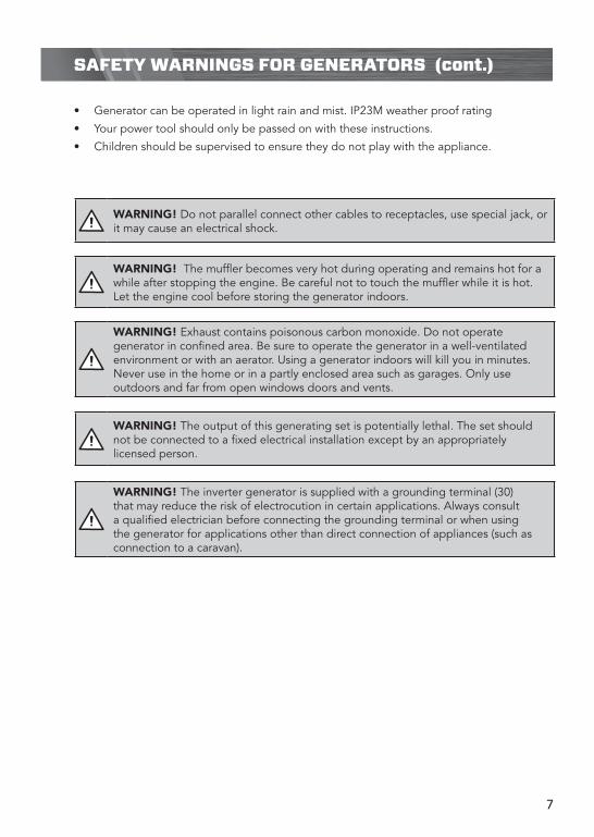
• Generator can be operated in light rain and mist. IP23M weather proof rating
• Your power tool should only be passed on with these instructions.
• Children should be supervised to ensure they do not play with the appliance.
WARNING! Exhaust contains poisonous carbon monoxide. Do not operate generator in confined area. Be sure to operate the generator in a well-ventilated environment or with an aerator. Using a generator indoors will kill you in minutes. Never use in the home or in a partly enclosed area such as garages. Only use outdoors and far from open windows doors and vents.
WARNING! The inverter generator is supplied with a grounding terminal (30) that may reduce the risk of electrocution in certain applications. Always consult a qualified electrician before connecting the grounding terminal or when using the generator for applications other than direct connection of appliances (such as connection to a caravan).
WARNING! The output of this generating set is potentially lethal. The set should not be connected to a fixed electrical installation except by an appropriately licensed person.
WARNING! The muffler becomes very hot during operating and remains hot for a while after stopping the engine. Be careful not to touch the muffler while it is hot. Let the engine cool before storing the generator indoors.
WARNING! Do not parallel connect other cables to receptacles, use special jack, or it may cause an electrical shock.

8
RISK OF ELECTROCUTION AND FIRE
Hazard What could happen How to prevent it
Improper storage of extension cord.
Extension cord can come into contact with hot engine parts resulting in damage. Using a damaged extension cord can result in electrocution or death.
Remove extension cord from the generator and store separately away from generator.
Operation of generator in heavy rain, wet, icy, or flooded conditions.
Water is an excellent conductor of electricity! Water which comes in contact with electrically charged components can transmit electricity to the frame and other surfaces, resulting in electrical shock to anyone contacting them.
Operate generator in a clean, dry, well ventilated area. Make sure hands are dry before touching unit.
Placing generator on or against highly conductive surface, such as a steel walkway or metal roof.
Accidental leakage of electrical current could charge conductive surfaces in contact with the generator.
Place generator on low conductivity surface such as a concrete slab.
ALWAYS operate generator a minimum of 2 meters from any conductive surface.
Operation of unit when damaged, or with guards or panels removed.
Attempting to use the unit when it has been damaged, or when it is not functioning normally could result in fire or electrocution.
Removal of guarding could expose electrically charged components and result in electrocution.
Do not operate generator with mechanical or electrical problem. Have unit repaired by an Authorized Service Centre.
Do not operate generator with protective guarding removed.

9
RISK OF FIRE
Hazard What could happen How to prevent it
Attempting to fill the fuel tank while the engine is running
Fuel and fuel vapours can become ignited by coming in contact with hot components such as the muffler, engine exhaust gases, or from an electrical spark.
Turn engine off and allow it to cool before adding fuel to the tank. Equip area of operation with a fire extinguisher certified to handle fuel fires.
Sparks, fire, hot objects
Cigarettes, sparks, fires, or other hot objects can cause fuel or fuel vapours to ignite.
Add fuel to tank in well ventilated area. Make sure there are no sources of ignition near the generator.
Improper storage of fuel
Improperly stored fuel could lead to accidental ignition. Fuel improperly secured could get into the hands of children or other unqualified persons.
Store fuel in an approved container designed to hold fuel. Store container in secure location to prevent use by others.
Tampering with factory set engine speed settings
Engine speed has been factory set to provide safe operation. Tampering with the engine speed adjustment could result in overheating of attachments and could cause a fire.
Never attempt to “speed-up” the engine to obtain more performance. Both the output voltage and frequency will be thrown out of standard by this practice, endangering attachments and the user.
Inadequate ventilation for generator
Materials placed against or near the generator or operating the generator in areas where the temperature exceeds 40° C. ambient (such as storage rooms or garages) can interfere with its proper ventilation features causing overheating and possible ignition of the materials or buildings.
Operate generator in a clean, dry, well ventilated area.
DO NOT OPERATE UNIT INDOORS OR IN ANY CONFINED AREA.
Overfilling the fuel tank - fuel spillage
Spilled fuel and its vapours can become ignited from hot surfaces or sparks.
Use care in filling the tank to avoid spilling fuel. Make sure fuel cap is secured tightly and check engine for fuel leaks before starting engine. Move generator away from refuelling area or any spillage before starting engine. Allow for fuel expansion. Never refuel with the engine running.

10
Hazard What could happen How to prevent it
Fire, Inhalation, Damage to Vehicle Surfaces
Fuel or oil can leak or spill and could result in fire or breathing hazard, serious injury or death can result. Fuel or oil leaks can damage carpet, paint or other surfaces in vehicles or trailers.
Transport fuel only in an approved fuel container. Always place generator on a protective mat when transporting to protect against damage to vehicle from leaks. Remove generator from vehicle immediately upon arrival at your destination.
RISK OF INJURY AND PROPERTY DAMAGE WHEN TRANSPORTING GENERATOR
Hazard What could happen How to prevent it
Contact with hot engine and generator components
Contact with hot surfaces, such as engines exhaust components, could result in serious burns.
During operation, touch only the control surfaces of the generator. Keep children away from the generator at all times. They may not be able to recognize the hazards of this product.
Hazard What could happen How to prevent it
Lifting a very heavy object
Serious injury can result from attempting to lift too heavy an object.
When lifting, always keep the object you are lifting near the vertical axis of your body. DO NOT use you back to lift heavy loads. Both people should crouch down, grab the underside of unit and use your legs to carry the weight. Keep the object as near the centre of your body’s gravity as possible. Avoid twisting your bodies when carrying the unit; instead, turn your whole body using your feet.
RISK OF HOT SURFACES
RISK FROM LIFTING

11
Hazard What could happen How to prevent it
Gasoline engines produce toxic carbon monoxide exhaust fumes
Breathing exhaust fumes will cause serious injury or death.
Operate generator in clean, dry, well ventilated area. Never operate unit in enclosed areas such as garages, basements, storage, sheds, or in any location occupied by humans or animals. Keep children, pets and others away from area of operating unit.
Hazard What could happen How to prevent it
Operation of generator in careless manner
All sources of energy include the potential for injury. Unsafe operation or maintenance of your generator could lead to serious injury or death to you or others.
Review and understand all of the operating instructions and warnings in this manual.
Become familiar with the operation and controls of the generator. Know how to shut it off quickly.
Equip area of operation with a fire extinguisher certified to handle gasoline or fuel fires.
Keep children or others away from the generator at all times.
Operating generator while suspended
Generator will not operate properly and will cause damage to the generator and could cause serious injury or death to you or others.
Never operate generator while suspended or in an unlevel position. Always operate generate on a flat, level surface.
RISK OF BREATHING - INHALATION HAZARD
RISK OF UNSAFE OPERATION
Hazard What could happen How to prevent it
Contact with moving parts can result in serious injury
The generator contains parts which rotate at high speed during operation. These parts are covered by guarding to prevent injury.
Never operate generator with guarding or cover plates removed. Avoid wearing loose fitting clothing or jewellery which could be caught by moving parts.
RISK OF MOVING PARTS
12
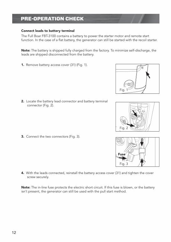
Connect leads to battery terminal
The Full Boar FBT-3100 contains a battery to power the starter motor and remote start function. In the case of a flat battery, the generator can still be started with the recoil starter.
Note: The battery is shipped fully charged from the factory. To minimize self-discharge, the leads are shipped disconnected from the battery.
1. Remove battery access cover (31) (Fig. 1).
2. Locate the battery lead connector and battery terminal connector (Fig. 2).
3. Connect the two connectors (Fig. 3).
4. With the leads connected, reinstall the battery access cover (31) and tighten the cover screw securely.
Note: The in-line fuse protects the electric short circuit. If this fuse is blown, or the battery isn’t present, the generator can still be used with the pull start method.
PRE-OPERATION CHECK
REMOTE CONTROL
12V DC 8.3A
12 V APPLIANCE OUTLET 8.3A
5V DC USB
BATTERY POWER
OVERLOAD RUN LOW OIL
STOP
ECONOMYON
ONOFF
240V
OFF
STOP
START
ONDC OVERLOAD
RESET
Fuse
Fig. 1
Fig. 2
Fig. 3

13
KNOW YOUR PRODUCT
Checking the oil
Note: The generator is shipped without oil and must be filled before starting. Oil tank capacity 450ml. (Use SAE30 or 15W40 oil).
1. Be sure to check that the generator is on a level surface with the engine stopped.
2. To check the oil level, first loosen the 2 cover screws and remove the rear maintenance cover (7) (Fig. 4).
3. Remove the oil filler cap, and wipe the dipstick with a clean rag. Check the oil level by inserting the dipstick in the filler hole without screwing it in and then removing it again (Fig. 5).
4. If the oil level is below the end of the dipstick, refill using oil fill bottle (10) until it registers on the halfway mark of the dipstick (Fig. 6). Use premium quality 4-stroke engine oil. Recommended SAE30 or 15W40 for most climate conditions in Australia.
Note. The Oil Alert System will automatically stop the engine before the oil level falls below the safe limit. However, to avoid the inconvenience of an unexpected shutdown, it is still advisable to visually inspect the oil level regularly.
PRE-OPERATION CHECK (cont.)
CAUTION! Using non-detergent oil or 2-stroke engine oil could shorten the engine’s service life.
REMOTE CONTROL
12V DC 8.3A
12 V APPLIANCE OUTLET 8.3A
5V DC USB
BATTERY POWER
OVERLOAD RUN LOW OIL
STOP
ECONOMYON
ONOFF
240V
OFF
STOP
START
ONDC OVERLOAD
RESET
Upper level allowed
Fig. 4
Fig. 5
Fig. 6
14
KNOW YOUR PRODUCT
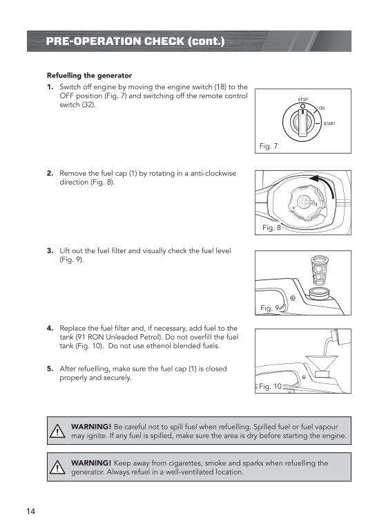
Refuelling the generator
1. Switch off engine by moving the engine switch (18) to the OFF position (Fig. 7) and switching off the remote control switch (32).
2. Remove the fuel cap (1) by rotating in a anti-clockwise direction (Fig. 8).
3. Lift out the fuel filter and visually check the fuel level (Fig. 9).
4. Replace the fuel filter and, if necessary, add fuel to the tank (91 RON Unleaded Petrol). Do not overfill the fuel tank (Fig. 10). Do not use ethenol blended fuels.
5. After refuelling, make sure the fuel cap (1) is closed properly and securely.
ON
STOP
START
ON
STOP
START
ON
STOP
START
REMOTE CONTROL
ON
OFF
REMOTE CONTROL
12V DC 8.3A
12 V APPLIANCE OUTLET 8.3A
5V DC USB
BATTERY POWER
OVERLOAD RUN LOW OIL
STOP
ECONOMYON
ONOFF
240V
OFF
STOP
START
ON
Fig. 9
Fig. 7
Fig. 8
Fig. 10
WARNING! Be careful not to spill fuel when refuelling. Spilled fuel or fuel vapour may ignite. If any fuel is spilled, make sure the area is dry before starting the engine.
WARNING! Keep away from cigarettes, smoke and sparks when refuelling the generator. Always refuel in a well-ventilated location.
PRE-OPERATION CHECK (cont.)

15
KNOW YOUR PRODUCT
Preparing to start
Note. Before starting the engine, disconnect all appliances from the generator.
1. Turn the fuel cap lever fully (2) clockwise to the ON position (Fig. 11).
2. Set the fuel valve (6) to the “ON” position (Fig. 12).
3. If the generator has not been used in a while or has run out of fuel, press the primer bulb (28) (Fig. 13) approx 5-10 times.
4. Put the electric start key (21) into the engine switch (18), and turn it to “ON” position (Fig. 14).
Starting the engine
There are three ways in which the generator can be started: Manual start, Key start and Remote start.
OPERATION
OFF
ON
REMOTE CONTROL
12V DC 8.3A
12 V APPLIANCE OUTLET 8.3A
5V DC USB
BATTERY POWER
OVERLOAD RUN LOW OIL
STOP
ECONOMYON
ONOFF
240V
OFF
STOP
START
ONDC OVERLOAD
RESET
ON
STOP
START
ON
STOP
START
ON
STOP
START
REMOTE CONTROL
ON
OFF
REMOTE CONTROL
12V DC 8.3A
12 V APPLIANCE OUTLET 8.3A
5V DC USB
BATTERY POWER
OVERLOAD RUN LOW OIL
STOP
ECONOMYON
ONOFF
240V
OFF
STOP
START
ON
Fig. 11
Fig. 12
Fig. 13
Fig. 14

16
OPERATION (cont.)
Manual start
1. Follow steps 1 to 4 in the “Preparing to start” section on the previous page.
2. Hold the carrying handle firmly with one hand. With the other hand, pull slightly on the rip cord (5) until you feel resistance and then pull hard and swiftly on the cord (Fig. 15). Do not let the rip cord retract by itself, guide it back by hand.
3. After the engine starts, allow it to run for a short period of time to warm up.
4. When using the manual start method, make sure that you use the key to turn the engine off after operation (Fig. 16), not the remote.
Note: Pressing and holding the emergency stop button (19) will stop the generator from any starting modes.
Key start
1. Follow steps 1 to 4 in the “Preparing to start” section on the previous page.
Note: The Battery power LED (14) illuminates when sufficient battery power is available
for a key start.
2. From the “ON” position turn the engine switch to the “START” position (Fig. 17).
3. After the engine starts, release the key and it will revert to the “ON” position (Fig 18). The engine should continue running.
4. When using the key start method, make sure that you use the key to turn the engine off after operating (Fig. 19), not the remote.
Note: Pressing and holding the emergency stop button (19) will stop the generator from all starting modes.
ON
STOP
START
ON
STOP
START
ON
STOP
START
REMOTE CONTROL
ON
OFF
REMOTE CONTROL
12V DC 8.3A
12 V APPLIANCE OUTLET 8.3A
5V DC USB
BATTERY POWER
OVERLOAD RUN LOW OIL
STOP
ECONOMYON
ONOFF
240V
OFF
STOP
START
ON
ON
STOP
START
ON
STOP
START
ON
STOP
START
REMOTE CONTROL
ON
OFF
REMOTE CONTROL
12V DC 8.3A
12 V APPLIANCE OUTLET 8.3A
5V DC USB
BATTERY POWER
OVERLOAD RUN LOW OIL
STOP
ECONOMYON
ONOFF
240V
OFF
STOP
START
ON
Fig. 15
Fig. 17 Fig. 18
Fig. 16
ON
STOP
START
ON
STOP
START
ON
STOP
START
REMOTE CONTROL
ON
OFF
REMOTE CONTROL
12V DC 8.3A
12 V APPLIANCE OUTLET 8.3A
5V DC USB
BATTERY POWER
OVERLOAD RUN LOW OIL
STOP
ECONOMYON
ONOFF
240V
OFF
STOP
START
ON
ON
STOP
START
ON
STOP
START
ON
STOP
START
REMOTE CONTROL
ON
OFF
REMOTE CONTROL
12V DC 8.3A
12 V APPLIANCE OUTLET 8.3A
5V DC USB
BATTERY POWER
OVERLOAD RUN LOW OIL
STOP
ECONOMYON
ONOFF
240V
OFF
STOP
START
ON
Fig. 19
17
OPERATION (cont.)
WARNING! Keep the generator away from other electric cables or wires such as distribution network.
WARNING! Limit operation requiring maximum power to 30 minutes. For continuous operation, do not exceed the rated power. In either case, the total wattage of all appliances connected must be considered .
WARNING! Do not exceed the current limit specified for any one receptacle.
WARNING! Keep the generator on a level surface when running. If generator is tilted while in operation, it may cause fuel spillage or low oil level warning.
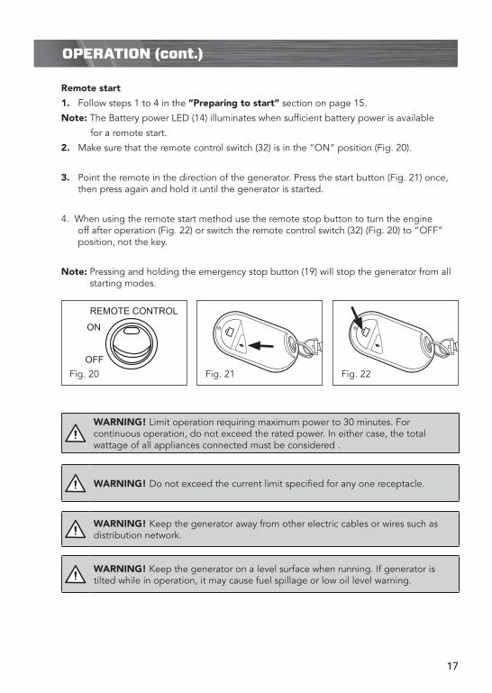
Remote start
1. Follow steps 1 to 4 in the “Preparing to start” section on page 15.
Note: The Battery power LED (14) illuminates when sufficient battery power is available
for a remote start.
2. Make sure that the remote control switch (32) is in the “ON” position (Fig. 20).
3. Point the remote in the direction of the generator. Press the start button (Fig. 21) once, then press again and hold it until the generator is started.
4. When using the remote start method use the remote stop button to turn the engine off after operation (Fig. 22) or switch the remote control switch (32) (Fig. 20) to “OFF” position, not the key.
Note: Pressing and holding the emergency stop button (19) will stop the generator from all starting modes.
ON
STOP
START
ON
STOP
START
ON
STOP
START
REMOTE CONTROL
ON
OFF
REMOTE CONTROL
12V DC 8.3A
12 V APPLIANCE OUTLET 8.3A
5V DC USB
BATTERY POWER
OVERLOAD RUN LOW OIL
STOP
ECONOMYON
ONOFF
240V
OFF
STOP
START
ON
Fig. 20 Fig. 21 Fig. 22

18
KNOW YOUR PRODUCT
ECON Switch (Fig. 23)
When the Econ Switch (15) is turned ON, the engine will automatically enter idle mode after an electrical appliance has been disconnected. It will return to the proper speed required when the appliance is connected. Having the Econ switch ON is recommended, as it minimizes the fuel consumption while in operation.
IMPORTANT!: In DC operation, turn the Econ switch to the OFF position.
WARNING! When an extension cable is required, be sure to use a rubber sheathed flexible cable. Limit length of extension cables: 60m for cables of 1.5mm2 and 100m for cables of 2.5mm2.
WARNING! Keep the generator a distance at least 1 metre from other equipment during operation.
ON
STOP
START
ON
STOP
START
ON
STOP
START
REMOTE CONTROL
ON
OFF
REMOTE CONTROL
12V DC 8.3A
12 V APPLIANCE OUTLET 8.3A
5V DC USB
BATTERY POWER
OVERLOAD RUN LOW OIL
STOP
ECONOMYON
ONOFF
240V
OFF
STOP
START
ON
Fig. 23
CAUTION! When high electrical loads are connected simultaneously, turn the Econ switch to the OFF position to reduce voltage vibration.
OPERATION (cont.)

19
OPERATION (cont.)
Output Indicator.
• The power indicator LED (12) (green) illuminates when power is available to outputs (Fig. 24).
Overload Indicator.
• If the generator is overloaded or if there is a short in the connected appliance the overload indicator LED (11) (red) will go ON and current to the connected appliance will be shut off (Fig. 25). The output indicator LED green will turn off.
• Substantial overloading that continuously lights the overload indicator light (red) may damage the generator. Marginal overloading that temporarily lights the overload indicator LED (11) (red) may shorten the service life of the generator. Stop the engine if the overload indicator light (red) switches ON and investigate the overload source.
• Before connecting an appliance to the generator, check that it is in good & order, and that its electrical rating does not exceed that of the generator.
• Be sure all equipment is turned off before plugging in the power cord.
• When an electric motor is started, both the overload indicator LED (red) (11) and the output indicator light (green) (12) may go on simultaneously. This is normal if the overload indicator LED (red) (11) goes off after about four seconds.
• If the overload indicator LED (red) stays on, contact customer service.
Oil alert indicator
• The oil alert system is designed to prevent engine damage caused by an insufficient amount of oil in the crankcase. Before the oil level in the crankcase falls below a safe limit, the oil alert system will automatically shut down the engine (the engine switch will remain in the ON position).
• If the oil alert system shuts down the engine, the oil alert indicator LED (red) (13) will come on when you operate the starter, and the engine will not run (Fig. 26). If this occurs, add engine oil.
OVERLOAD RUN LOW OIL
240V AC
USB
12V DC 8.3ABATTERY CHARGE
REMOTECONTROL
STOP
ECON
12V APPLIANCE OUTLET 8.3A
ON OFF
ON
ON
START
OFF
ON OFF
5V DC USB
OVERLOAD RUN LOW OIL
240V AC
USB
12V DC 8.3ABATTERY CHARGE
REMOTECONTROL
STOP
ECON
12V APPLIANCE OUTLET 8.3A
ON OFF
ON
ON
START
OFF
ON OFF
5V DC USB
OVERLOAD RUN LOW OIL
240V AC
USB
12V DC 8.3ABATTERY CHARGE
REMOTECONTROL
STOP
ECON
12V APPLIANCE OUTLET 8.3A
ON OFF
ON
ON
START
OFF
ON OFF
5V DC USB
OVERLOAD RUN LOW OIL
240V AC
USB
12V DC 8.3ABATTERY CHARGE
REMOTECONTROL
STOP
ECON
12V APPLIANCE OUTLET 8.3A
ON OFF
ON
ON
START
OFF
ON OFF
5V DC USB
OVERLOAD RUN LOW OIL
240V AC
USB
12V DC 8.3ABATTERY CHARGE
REMOTECONTROL
STOP
ECON
12V APPLIANCE OUTLET 8.3A
ON OFF
ON
ON
START
OFF
ON OFF
5V DC USB
OVERLOAD RUN LOW OIL
240V AC
USB
12V DC 8.3ABATTERY CHARGE
REMOTECONTROL
STOP
ECON
12V APPLIANCE OUTLET 8.3A
ON OFF
ON
ON
START
OFF
ON OFF
5V DC USB
OVERLOAD RUN LOW OIL
240V AC
USB
12V DC 8.3ABATTERY CHARGE
REMOTECONTROL
STOP
ECON
12V APPLIANCE OUTLET 8.3A
ON OFF
ON
ON
START
OFF
ON OFF
5V DC USB
OVERLOAD RUN LOW OIL
240V AC
USB
12V DC 8.3ABATTERY CHARGE
REMOTECONTROL
STOP
ECON
12V APPLIANCE OUTLET 8.3A
ON OFF
ON
ON
START
OFF
ON OFF
5V DC USB
OVERLOAD RUN LOW OIL
240V AC
USB
12V DC 8.3ABATTERY CHARGE
REMOTECONTROL
STOP
ECON
12V APPLIANCE OUTLET 8.3A
ON OFF
ON
ON
START
OFF
ON OFF
5V DC USB
Fig. 24
Fig. 25
Fig. 26
20
OPERATION (cont.)
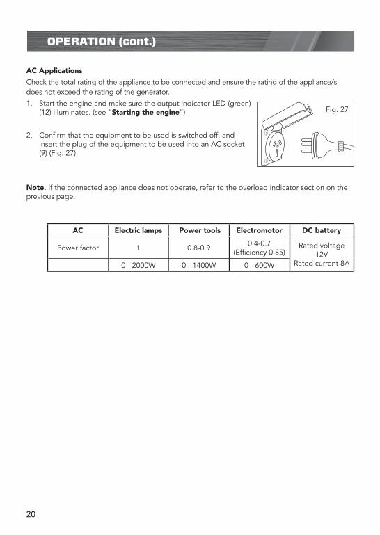
AC Applications
Check the total rating of the appliance to be connected and ensure the rating of the appliance/s does not exceed the rating of the generator.
1. Start the engine and make sure the output indicator LED (green) (12) illuminates. (see “Starting the engine”)
2. Confirm that the equipment to be used is switched off, and insert the plug of the equipment to be used into an AC socket (9) (Fig. 27).
Note. If the connected appliance does not operate, refer to the overload indicator section on the previous page.
Fig. 27
AC Electric lamps Power tools Electromotor DC battery
Power factor 1 0.8-0.9 0.4-0.7 (Efficiency 0.85)
Rated voltage 12V
Rated current 8A 0 - 2000W 0 - 1400W 0 - 600W

21
DC Applications
The DC output on this generator has a rated voltage of 12V with a rated current of 8.3A. When using the DC output (16), turn the Econ switch (15) to the OFF position.
The USB outlet (20) outputs power with a rating of 1A at 5V. It is suitable for charging mobile phones, MP3 players etc. Before plugging the appliance into the USB port, check that its rating does not exceed 1A or 5W. Allow the generator to warm up before connecting the appliance to the USB outlet.
The appliance outlet (16) will run most 12V appliances fitted with the car cigarette lighter type plug (Fig. 29), rated up to 8.3A. It is suitable for running small compressors, blowers, small refrigerators, etc. that can usually be run through the cigarette lighter socket of a car (it is not however, suitable for cigarette lighters).
Before plugging an appliance into the appliance outlet (16) (Fig. 30), check that its rating does not exceed 8.3A or 100W and that it is turned off. Allow the generator to warm up before opening the cover and connecting the appliance to the appliance outlet.
Note. The DC receptacle can be used while the AC power is in use. If you use both at the same time, be sure not to exceed the total power for AC and DC.
An overloaded DC circuit will trip the DC circuit breaker (17). If this happens, disconnect the DC load before pushing in the circuit breaker reset switch (17) to resume operation (Fig. 31).
When reconnecting appliances, reduce the load which previously overloaded the generator.
OPERATION (cont.)
REMOTE CONTROL
12V DC 8.3A
12 V APPLIANCE OUTLET 8.3A
5V DC USB
BATTERY POWER
OVERLOAD RUN LOW OIL
STOP
ECONOMYON
ONOFF
240V
OFF
STOP
START
ON
REMOTE CONTROL
12V DC 8.3A
12 V APPLIANCE OUTLET 8.3A
5V DC USB
BATTERY POWER
OVERLOAD RUN LOW OIL
STOP
ECONOMYON
ONOFF
240V
OFF
STOP
START
ON
REMOTE CONTROL
12V DC 8.3A
12 V APPLIANCE OUTLET 8.3A
5V DC USB
BATTERY POWER
OVERLOAD RUN LOW OIL
STOP
ECONOMYON
ONOFF
240V
OFF
STOP
START
ON
REMOTE CONTROL
12V DC 8.3A
12 V APPLIANCE OUTLET 8.3A
5V DC USB
BATTERY POWER
OVERLOAD RUN LOW OIL
STOP
ECONOMYON
ONOFF
240V
OFF
STOP
START
ON
REMOTE CONTROL
12V DC 8.3A
12 V APPLIANCE OUTLET 8.3A
5V DC USB
BATTERY POWER
OVERLOAD RUN LOW OIL
STOP
ECONOMYON
ONOFF
240V
OFF
STOP
START
ON
REMOTE CONTROL
12V DC 8.3A
12 V APPLIANCE OUTLET 8.3A
5V DC USB
BATTERY POWER
OVERLOAD RUN LOW OIL
STOP
ECONOMYON
ONOFF
240V
OFF
STOP
START
ON
ON
STOP
START
ON
STOP
START
ON
STOP
START
REMOTE CONTROL
ON
OFF
REMOTE CONTROL
12V DC 8.3A
12 V APPLIANCE OUTLET 8.3A
5V DC USB
BATTERY POWER
OVERLOAD RUN LOW OIL
STOP
ECONOMYON
ONOFF
240V
OFF
STOP
START
ON
Fig. 28
Fig. 29
Fig. 30
Fig. 31

22
The 12V battery charging outlet (29) is suitable for charging most lead acid type car batteries.
Before charging, remove the battery from the vehicle. The battery MUST be totally isolated from any other circuitry.
1. Connect the positive (+, RED) charging cord to the positive battery terminal. Connect the negative (-, BLACK) charging cord to the negative battery terminal (Fig. 32). Do not reverse the charging cables, or serious damage to the generator and/or the battery may occur.
2. Start the generator and allow it to warm up (see Starting the generator)
3. Connect the DC cable (23) to battery charging outlet (29) (Fig. 33). The battery will begin charging.
4. When disconnecting, remove the plug from the generator before unclipping the clamps on the battery.
Note: Do not attempt to charge lithium ion, NiCad or NiMH batteries. The charging outlet (29) is only intended for Lead Acid batteries.
OPERATION (cont.)
REMOTE CONTROL
12V DC 8.3A
12 V APPLIANCE OUTLET 8.3A
5V DC USB
BATTERY POWER
OVERLOAD RUN LOW OIL
STOP
ECONOMYON
ONOFF
240V
OFF
STOP
START
ON
REMOTE CONTROL
12V DC 8.3A
12 V APPLIANCE OUTLET 8.3A
5V DC USB
BATTERY POWER
OVERLOAD RUN LOW OIL
STOP
ECONOMYON
ONOFF
240V
OFF
STOP
START
ON
Fig. 32
Fig. 33
WARNING! The battery gives off explosive gases; keep sparks, flames and cigarettes away. Provide adequate ventilation when charging.
WARNING! The battery contains sulphuric acid (electrolyte). Contact with skin or eyes may cause severe burns. Wear protective equipment.
WARNING! Batteries left unattended can potentially explode, resulting in serious injury.

23
Stopping the engine
Emergency stop button
If the situation arises that there is no key or remote control on hand and the generator needs to be urgently stopped, the emergency stop button (19) can be used.
Press and hold down the button until the engine stops.
In normal use:
1. Switch off the connected equipment and pull out the plug.
2. If you have started the generator with the remote control, you should stop it by pressing the stop button on the remote control (Fig. 35).
3. If you have started the generator with the key, or the rip cord, you should stop it by turning the key in the engine switch (18) to the OFF position (Fig. 36)
4. Turn the fuel cap lever (2) fully counter clockwise to the
“OFF” position (Fig. 37).
5. Turn the fuel valve lever (6) to the OFF position (Fig. 38).
OPERATION (cont.)
ON
STOP
START
ON
STOP
START
ON
STOP
START
REMOTE CONTROL
ON
OFF
REMOTE CONTROL
12V DC 8.3A
12 V APPLIANCE OUTLET 8.3A
5V DC USB
BATTERY POWER
OVERLOAD RUN LOW OIL
STOP
ECONOMYON
ONOFF
240V
OFF
STOP
START
ON
Fig. 35
Fig. 36
CAUTION! Be sure both the fuel cap lever (2), the engine switch (18) and remote control switch (19) are in “OFF” position when stopping, transporting and/or storing the generator.
REMOTE CONTROL
12V DC 8.3A
12 V APPLIANCE OUTLET 8.3A
5V DC USB
BATTERY POWER
OVERLOAD RUN LOW OIL
STOP
ECONOMYON
ONOFF
240V
OFF
STOP
START
ONDC OVERLOAD
RESET
Fig. 34
Fig. 37
OFF
ONFig. 38

24
MAINTENANCE
The purpose of the maintenance and adjustment schedule is to keep the generator in the best operating condition.
Inspect or service as scheduled in the table below.
WARNING! Shut off the engine before performing any maintenance. If the engine must be run, make sure the area is well ventilated. The exhaust contains poisonous carbon monoxide gas.
CAUTION! Use authorized parts or their equivalent. The use of replacement parts which are not of equivalent quality may damage the generator.
REGULAR SERVICE PERIOD (1)EACH USE
FIRST MONTH
OR 20HRS
EVERY 3 MONTHS
OR 50 HRS
EVERY 6 MONTHS
OR 100 HRS
EVERY YEAR OR 200 HRS
ITEM. Perform at every indicated month or operating hour interval, whichever comes first.
Engine oilCheck level •Change • •
Air cleanerCheck •Clean • (2)
Spark plug Check - adjust •Spark arrester Clean •Valve clearance Check - adjust • (3)
Fuel tank & filter Clean • (3)
Fuel line Check Every 2 years (Replace if necessary) (3)
NOTE:
(1) Log hours of operation to determine proper maintenance.
(2) Service more frequently when used in dusty areas.
(3) Servicing of this product can be arranged by contacting customer service.
Telephone: 1800 069 486.

25
MAINTENANCE (cont.)
Changing oil
Drain the oil while the engine is still warm to ensure rapid and complete draining.
1. Unscrew the two screws on the left side maintenance cover (7) and remove (Fig. 39).
2. Remove the oil cap and replace it with the oil lead pipe (24) (Fig. 40).
3. Tilt the generator and spill out the oil into a suitable container (Fig. 41).
4. Refill with new oil and check the oil level with the dipstick (Fig. 42).
5. Reinstall the left side maintenance cover (7) and tighten the cover screw securely.
Note. Wash your hands with soap and water after handing used oil.
Note. Please dispose of used motor oil in a manner that is compatible with the environment. Do not throw it in the trash or pour it on the ground.
WARNING! Make sure to turn the engine switch (15), the fuel cap vent lever (2) and remote control switch (19) OFF before draining.
Upper level allowed
Fig. 40
Fig. 39
Fig. 42Fig. 41
REMOTE CONTROL
12V DC 8.3A
12 V APPLIANCE OUTLET 8.3A
5V DC USB
BATTERY POWER
OVERLOAD RUN LOW OIL
STOP
ECONOMYON
ONOFF
240V
OFF
STOP
START
ONDC OVERLOAD
RESET

26
KNOW YOUR PRODUCT
REMOTE CONTROL
12V DC 8.3A
12 V APPLIANCE OUTLET 8.3A
5V DC USB
BATTERY POWER
OVERLOAD RUN LOW OIL
STOP
ECONOMYON
ONOFF
240V
OFF
STOP
START
ONDC OVERLOAD
RESET
Air cleaner serviceA dirty air cleaner will restrict air flow to the carburettor. To prevent carburettor malfunction,service the air cleaner regularly. Service more frequently when operating the generator inextremely dirty areas.
1. Loosen the 2 cover screws and remove the left side maintenance cover (7) (Fig. 43).
2. Remove the three small screws from the air cleaner body, slide out the air cleaner cartridge (Fig. 44).
3. Remove the air filter from the cartridge (Fig. 45). Check to be sure it is clean and in good condition. Brush off any dry particles or dislodge them by tapping the air filter on a hard surface. Replace the filter if necessary.
Note. It is normal for a little oil to appear under the air filter box if the generator is running for a long period of time, or if a lot of oil is in the engine. Wipe up the excess oil after each use and after stopping the generator.
CAUTION! Never run the engine without the air cleaner. Rapid engine wear will result from contaminants such as dust and dirt being drawn through the carburettor, into the engine.
Fig. 43
Fig. 44
Fig. 45
WARNING! Do not use petrol or low flash point solvents for cleaning. They are flammable and explosive under certain conditions.
MAINTENANCE (cont.)

27
Spark plug servicingUse only good quality spark plugs. To ensure proper engine operation, the spark plug must be properly gapped and free of deposits.
1. Remove the screw on the top maintenance cover (8) and slide the cover off (Fig. 46).
2. Take out the spark plug lead and rubber cover (Fig. 47).
3. Remove the spark plug with spark plug socket (3).
4. Visually inspect the spark plug. Discard it if the insulator is cracked or chipped. The gap should be between 0.6 – 0.8mm (Fig 48). Clean spark plug with a wire brush if it is to be reused.
5. Install the spark plug carefully by hand, to avoid cross-threading. Tighten it securely with provided spark plug wrench.
6. Reinstall the ignition coil rubber boot on the spark plug securely.
7. Reinstall the top maintenance cover (8).
WARNING! The spark plug must be securely tightened. An improperly tightened plug can become very hot and possibly damage the generator.
REMOTE CONTROL
12V DC 8.3A
12 V APPLIANCE OUTLET 8.3A
5V DC USB
BATTERY POWER
OVERLOAD RUN LOW OIL
STOP
ECONOMYON
ONOFF
240V
OFF
STOP
START
ONDC OVERLOAD
RESET
Fig. 47
Fig. 48
Fig. 46
0.6 – 0.8mm
MAINTENANCE (cont.)

28
MAINTENANCE (cont.)
Muffler - Fire net
An uncleaned muffler will make a lot of noise and affect the engine’s performance.
Clean the fire net periodically, to ensure normal operation. It is particularly important to maintain the fire net if the generator is being used in dirty/dusty environment.
Remove the two screws on the fire net, then remove the fire net (Fig. 49). Clean or replace it if necessary.
Fuel Filter
A dirty fuel filter will restrict fuel flow to the carburettor. Replace fuel filter if it becomes noticeably discoloured. The fuel filter is located behind the rear maintenance cover (7) (Fig. 50).
WARNING! Before cleaning the fire net of the muffler, make sure the generator is switched off. Make sure that the machine has cooled in order to avoid scalding by the hot muffler.
Fig. 49
Fig. 50

29
TRANSPORTING & STORAGE
To prevent fuel spillage when transporting or during temporary storage, the generator should be secured upright in its normal operating position, with the engine switch OFF.
The fuel cap vent lever (2) and Fuel valve (6) should be turned to the OFF position.
Allow the engine to cool well before turning the fuel cap vent lever to the OFF position.
When transporting generator:
• When transporting a short distance, it is advisable that you use the retractable handle (26). The retractable handle can be extended out from its position at the front base of the generator (Fig 51). Along with the wheels at the rear base of the unit (27), the retractable handle makes transporting easy over short distances.
• Do not overfill the tank (there should be no fuel in the filler neck).
• Do not operate the generator while it is on a vehicle. Take the generator off the vehicle and use it in a well ventilated place.
• Avoid direct sunlight when transporting the generator on a vehicle. If the generator is left in an enclosed vehicle for many hours, high temperatures inside the vehicle could cause fuel to vaporize, resulting in a possible explosion.
• Do not drive on a rough road for an extended period with the generator on board. If you must transport the generator on a rough road, drain the fuel from the generator beforehand.
Before storing the unit for an extended period:
1. Be sure the storage area is free of excessive humidity and dust.
2. Completely drain the fuel from the tank. Open the fuel valve (6), start the engine and operate it in the idle position until all remaining fuel is gone and the engine stops automatically.
4. Discharge oil (see steps 1-3 of “Changing the oil”).
5. Check the fuel tap (6) is turned off (Fig. 52).
6. Check the cap vent (2) is turned to the OFF position (Fig. 53)
WARNING! Gasoline is extremely flammable and explosive under certain conditions. Do not smoke or allow flames or sparks in the area. OFF
ON
Fig. 51
Fig. 52
Fig. 53
30
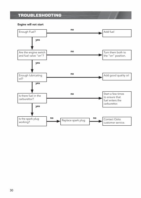
TROUBLESHOOTING
Enough Fuel? Add fuel
Are the engine switch and fuel valve “on”?
Turn them both to the “on” position.
Enough lubricating oil?
Add good quality oil
Is there fuel in the carburettor?
Start a few times to ensure that fuel enters the carburettor.
Is the spark plug working?
Replace spark plug Contact Ozito customer service.
yes
yes
yes
yes
no no
no
no
no
no
Engine will not start

31
DESCRIPTION OF SYMBOLS
Power tools that are no longer usable should not be disposed of with household waste but in an environmentally friendly way. Please recycle where facilities exist. Check with your local council authority for recycling advice.
Recycling packaging reduces the need for landfill and raw materials. Reuse of recycled material decreases pollution in the environment. Please recycle packaging where facilities exist. Check with your local council authority for recycling advice.
Read instruction manual
Extremely hot surface. Do not touch a hot mu�er or exhaust system. You may get burned. These parts get extremely hot from operation and remain hot a short time after the unit is turned o�.
Exhaust contains poisonous carbon monoxide. Do not operate generator in con�ned area.
Do not parallel connect other cables to receptacles, use special jack, or it may cause an electrical shock.
min-1
HOT !
Toxic FumesKeep bystanders away
Unleaded Petrol Four stroke engine oil
Do not smoke
Engine may continue to rotate after machine is switched o�
Ground
Hot surface
CARING FOR THE ENVIRONMENT
32
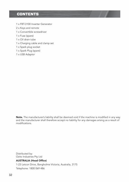
CONTENTS
Distributed by: Ozito Industries Pty Ltd
AUSTRALIA (Head Office)
1-23 Letcon Drive, Bangholme Victoria, Australia, 3175
Telephone: 1800 069 486
Note. The manufacturer’s liability shall be deemed void if the machine is modified in any way and the manufacturer shall therefore accept no liability for any damages arising as a result of modifications.
1 x FBT-3100 Inverter Generator
2 x Keys and remote
1 x Convertible screwdriver
1 x Fuse (spare)1 x Oil drain tube1 x Charging cable and clamp set1 x Spark plug socket1 x Spark Plug (spare)1 x USB Adaptor

33

34
WARRANTY EXCLUSIONS
The following actions will result in the warranty being void.
If the tool has been operated on a supply voltage other than that specified on the tool.• If the tool shows signs of damage or defects caused by or resulting from abuse, accidents • or alterations.Failure to perform maintenance as set out within the instruction manual.• If the tool is disassembled or tampered with in any way.The warranty excludes damage resulting from product misuse or product neglect.
•
•
This warranty is given by Ozito Industries Pty Ltd. ABN: 17 050 731 756Ph.1800 069 486Australia/New Zealand (Head Office)1-23 Letcon Drive, Bangholme, Victoria, Australia 3175
FB1
WARRANTY
TO ENSURE A SPEEDY RESPONSE PLEASE HAVE THE MODEL NUMBER AND DATE OF PURCHASE AVAILABLE. A CUSTOMER SERVICE REPRESENTATIVE WILL TAKE YOUR CALL AND ANSWER ANY QUESTIONS YOU MAY HAVE RELATING TO THE WARRANTY POLICY
OR PROCEDURE.
The benefits provided under this warranty are in addition to other rights and remedies whichare available to you under law. The warranty covers manufacturer defects in materials, workmanship and finish under normal use.
1 YEAR WARRANTYYour product is guaranteed for a period of 12 months from the original date of purchase.If a product is defective it will be repaired in accordance with the terms of this warranty.Warranty excludes consumable parts, for example: wheels, bearings.
Our goods come with guarantees that cannot be excluded under Australian Consumer law & Consumer Guarantees Act 1993 (NZ). You are entitled to a replacement or refund for a major failure and to compensation for other reasonably foreseeable loss or damage. You are also entitled to have the goods repaired and replaced if the goods fail to be of acceptable quality and the failure does not amount to a major failure.
`Australia 1800 069 486New Zealand 0508 069 486
YOUR WARRANTY FORM SHOULD BE RETAINED BY YOU AT ALL TIMES. IN ORDER TO MAKE A CLAIM UNDER THIS WARRANTY YOU MUST RETURN THE PRODUCT TO YOUR NEAREST
BUNNINGS WAREHOUSE (see www.bunnings.com.au or www.bunnings.co.nz for store locations) WITH YOUR BUNNINGS REGISTER RECEIPT. PRIOR TO RETURNING YOUR PRODUCT FOR
WARRANTY PLEASE TELEPHONE OUR CUSTOMER SERVICE HELPLINE: