inverter owner's installation manual kit - carid.com · pdf fileplease note that for the...
TRANSCRIPT

InverterInstallationKit
DC-1000-KITDC-2000-KITDC-2500-KITDC-3500-KIT
Please read this manual before installing your DC Inverter Installation Kit
owner's Manual
2 | SAMLEX AMERICA INC.
Preventing Fire and explosion HazardsWorking with the inverter may produce arcs or sparks. Thus, the inverter should not be used in areas where there are inflammable materials or gases requiring ignition protected equipment.
These areas may include spaces containing gasoline powered machinery, fuel tanks, battery compartments.
Precautions When Working with Batteries
• batteries contain very corrosive diluted Sulphuric Acid as electrolyte. Precautions should be taken to prevent contact with skin, eyes or clothing.
• batteries generate Hydrogen and oxygen during charging resulting in evolution of explosive gas mixture. Care should be taken to ventilate the battery area and follow battery manufacturer’s recommendations.
• Never smoke or allow a spark or flame near the batteries.
• Use caution to reduce risk of dropping a metal tool on the battery. It could spark or short circuit the battery or other electrical parts and could cause an explosion.
• remove metal items like rings, bracelets and watches when working with batteries. batteries can produce short circuit current high enough to weld a ring or the like to metal causing a severe burn.
• If you need to remove a battery, always remove the Negative terminal from the battery first.
Make sure that all the accessories are off so that you do not cause a spark.
installation and wiring compliance Installation and wiring must comply with
the local and National electrical Codes and must be done by a CerTIfIeD eleCTrICIAN.
sectIOn 1 | Important safety Precautions
!

The Inverter Installation Kit consists of two cables and fuse arrangement for connecting the battery to the inverter in a safe manner.
Fuse Protection in the Battery circuitA battery is an unlimited source of current. Under short circuit conditions, a battery can supply thousands of Amperes of current. If there is a short circuit along the length of the cables that connect the battery to the inverter, thousands of Amperes of current can flow from the battery to the point of shorting and that section of the cable will overheat, the insulation will melt and the cable will ultimately break. This interruption of very high current will generate a hazardous, high temperature, high energy arc with accompanying high pressure wave that may cause fire, damage nearby objects and cause injury. To prevent an occurrence of hazardous conditions under short circuit conditions, an appropriate fuse should be used in the battery circuit that has the required current interrupting capacity (Termed AIC – Ampere Interrupting Capacity). for this purpose, a fuse with AIC rating of 10000A at 14V / 5000A at 32V, or higher should be used. The following types of fuses are included in the Kit:
• 400A, 125 VDc, Model JLLn 400 manufactured by Littelfuse - AIC of 20,000A - Ul Class “T” rated, Ul listed as per Ul Standard 248-15
• Marine Rated Battery Fuse (MRBF Series) made by cooper Bussmann - Voltage rating of max 58 VDC - Current ratings of 100A (Mrbf-100), 200A (Mrbf-200) and 300A (Mrbf-300) - AIC of 10000A at 14VDC, 5000A at 32 VDC and 2000A at 58 VDC - Ignition protected as per SAe J1171 - Weather Proof (IP66)
! cAution the fuse should be placed as close to the battery’s PoSitiVe terminal as possible, preferably within 7” of the battery terminal.
Sizing of cables to Reduce Voltage Drop, Heating and Power Lossflow of electric current in a conductor is opposed by the resistance of the conductor. The resistance of the conductor increases linearly as the length of the conductor is increased and decreases as the cross-section (thickness) of the conductor is increased. flow of current through the resistance of the conductor produces voltage drop and power loss due to heating. Voltage drop due to resistance of the conductor increases linearly as the current increases.
Power loss because of heating due to resistance of the conductor increases by the square of the increase in the current - e.g. if the current increases 2 times, the heating / power loss increases 4 times. Thus, it is desirable that thicker and shorter conductors be used to reduce the undesirable effects of voltage drop, heating and power loss.
sectIOn 2 | General

4 | SAMLEX AMERICA INC.
The size (thickness / cross-section) of the conductors is designated by AWG (American Wire Gauge). Please note that a smaller AWG # denotes a thicker size of the conductor up to AWG #1. Wires thicker than AWG #1 are designated AWG #1/0, AWG #2/0, AWG #3/0 and so on. In this case, increasing AWG # X/0 denotes thicker wire. DC input circuit of an inverter is required to handle very large DC currents. Cables and connectors from the battery to the inverter should be properly sized to ensure minimum voltage drop, minimum heating and minimum power loss between the battery and the inverter. Thinner cables and loose connections will result in larger voltage drop, increased loss of power and consequent reduction in efficiency, poor inverter performance and will produce abnormal heating that may lead to risk of insulation melt down and fire. for safety against overheating and consequent deterioration of the insulation and possibility of fire, the National Electrical Code (NEC) specifies the maximum current carrying capacity (Ampacity) of various types of cables for installation in free air. Apart from the consideration of safety as explained above, reducing the voltage drop as a result of longer distance of the cable between the battery and the inverter is also important for improving the efficiency of the DC input side of the inverter system. longer distance between the battery and the cable will require thicker cable. Normally, the thickness of the cable should be such that the voltage drop from the battery terminal to the inverter is as low as possible, preferably less than 5%. Inverters are designed to operate normally within a specified lower and upper input voltage range. The lower operating voltage limit of inverters is normally 10V, 20V and 40V for 12V, 24V and 48V battery systems respectively. When this limiting voltage is seen at the input terminal of the inverter, it will shut down due to low input voltage protection. Thus, if there is excessive voltage drop in the input connection between the battery and the inverter due to thinner cable / longer distance / larger current, the inverter will shut down even if the battery is fully charged.
As the distance between the battery and the inverter may vary depending upon the user requirement, 10 ft length of cable is provided in the Inverter Installation Kits for convenience. The specifications of the Kits include the approximate voltage drops for distances of 3, 6 and 10 ft. between the battery and the inverter.
Please note that for the purposes of the calculation of the voltage drop based on the resistance per unit length, the length of the cable has been taken as twice the distance between the battery and the inverter to include the overall length of the Positive and Negative cables (e.g. if the distance between the battery and the inverter is taken as 3 ft., the length of the cable has been taken as 6 ft. for calculation purposes).
Please ensure that the distance between the battery and the inverter is kept as short as possible to limit the voltage drop to less than 5%. cut off the extra length of cable if the distance between the battery and the inverter is less than 10 ft.
sectIOn 2 | General

characteristics of the cable Provided with the KitsWe have provided the highest quality, industrial / welding grade, flexible cable with the Kits. These cables are designed for use as motor and power leads where flexibility and portability are required. The inherent nature of the design makes the cables suitable for battery cables for automotive and renewable energy applications.
Key features of the cables provided with the Kits are as follows:
• 600V rating
• Very wide operating temperature of -50oC to 105oC
• High strand count, annealed, copper conductors for high flexibility.
• ethylene Propylene rubber (ePr) jacket provides the high 600V insulation and resistance to abrasion, oils, acids and heat.
characteristics of Fuses and Fuse Holders Provided with the KitsDC-1000-KIT, DC-2000-KIT and DC-2500-KIT are provided with 100A, 200A and 300A fuses respectively (fig. 3.3). These fuses are Marine rated battery fuses (Mrbf-XXX Series) made by Cooper bussmann.
The Mrbf fuse provides easy, practical weatherproof and economical circuit protection in tight space constraints. The fuse is installed between the Positive battery Terminal Stud and the Positive battery Cable with the help of a special Clamping fixture. The Clamping fixture consists of the following:
• Clamping fixture bar (CfbAr), fig. 3.4. Has a base plate for connecting to the battery stud (with a hole to accommodate battery stud of up to stud size 3/8” / M10) and a stud (size M-8) for connecting the Mrbf fuse and the battery cable.
• Stainless Steel nut (thread size M8, will require ½” or 13 mm wrench for tightening), flat Washer and Spring Washer, fig. 3.5.
• An Insulating Cap, fig. 3.6. It slides over the base plate of CfbAr and is used to insulate the exposed stud and the nut of the CfbAr.
tools Required
• Wire Cutting Tool and Wire Stripper (for DC-3500-KIT)
• ½” Wrench and 5/16” Allen Key (for Samlex DC-3500-KIT)
• Appropriate screw driver or wrench depending on the DC input terminal of your inverter.
• Crimping tool and heat shrink tubing (if ring terminal for the inverter end is being changed to fit DC input terminals of the inverter).
sectIOn 2 | General

6 | SAMLEX AMERICA INC.
Dc-1000-Kit, Dc-2000-Kit, AnD Dc-2500-Kit inStALLAtion inStRuctionS
Preparing cable termination for inverter end• The cables provided in the kits have copper ring
terminals on both the ends.
• The ring terminal may not fit the DC input terminal on the inverter and may need to be reshaped / replaced with cable lugs provided with the inverter.
• Some inverters require Pin Type of terminal lugs to fit DC input connectors with a cylindrical hole and set screw. As the terminal lug fitted on the cable is made of copper which is malleable, it can be beaten with a hammer to form a pin shape of the required diameter to fit the cylindrical hole.
• It may be necessary to remove the cable lug and crimp the new lug provided with the inverter.
A. Identify the Positive & Negative cables• Positive cable: red color with terminal lugs at
each end as in fig. 3.1.
• negative cable: black color with terminal lugs at each end as in fig. 3.2.
B. Connect one end of the Positive cable to the Positive terminal of the inverter (usually red in color). The terminal lug may need to be shaped/replaced to fit the inverter terminal (see details above).
c. Identify the components of the fuse Assembly. refer to figures 3.3 to 3.6.
D. Place the Mrbf fuse onto the stud provided on the CfbAr. See fig.3.7. e. Next, place the cable lug (crimped to the free end of the Positive cable) onto the CfbAr stud so that it sits over the fuse Mrbf. See fig. 3.8.
F. Next, attach the flat washer, the spring washer and the M-8 nut on to the CfbAr stud and tighten the nut with a ½” wrench. See fig. 3.9. G. Slide the Insulating Cap onto the rectangular strip of the CfbAr and then place the hood portion over the exposed portion of the stud of the CfbAr. See figures 3.10 and 3.11.
fig. 3.2. Negative Cable end
fig. 3.1. Positive Cable end
fig. 3.3. Marine rated battery fuse (Mrbf)
fig. 3.4. Clamping fixture bar (CfbAr)
sectIOn 3 | Installation Instructions

fig. 3.10. Insulating Cap slid over the rectangular portion of CfbAr
fig. 3.11. CfbAr with fitted fuse Mrbf
fig. 3.9. Mrbf fuse and Positive cable fixed to the CfbAr
fig. 3.7. Mrbf fuse inserted onto the stud on CfbAr
fig. 3.6. Insulating cap
fig. 3.5. M-8 Nut, flat Washer and Spring Washer
fig. 3.8.
sectIOn 3 | Installation Instructions
8 | SAMLEX AMERICA INC.
Dc-1000-Kit, Dc-2000-Kit, AnD Dc-2500-Kit inStALLAtion inStRuctionS (continued)
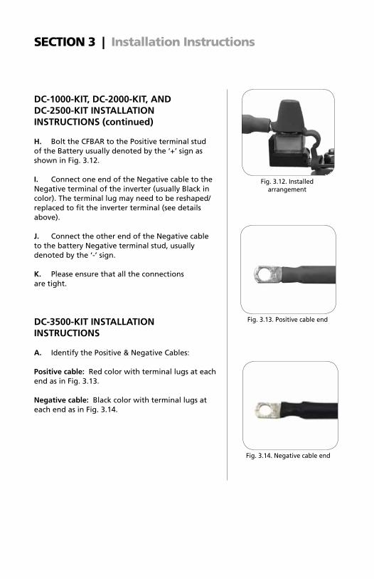
H. bolt the CfbAr to the Positive terminal stud of the battery usually denoted by the ‘+’ sign as shown in fig. 3.12.
i. Connect one end of the Negative cable to the Negative terminal of the inverter (usually black in color). The terminal lug may need to be reshaped/replaced to fit the inverter terminal (see details above).
J. Connect the other end of the Negative cable to the battery Negative terminal stud, usually denoted by the ‘-’ sign.
K. Please ensure that all the connections are tight.
Dc-3500-Kit inStALLAtion inStRuctionS
A. Identify the Positive & Negative Cables: Positive cable: red color with terminal lugs at each end as in fig. 3.13.
negative cable: black color with terminal lugs at each end as in fig. 3.14.
fig. 3.12. Installed arrangement
fig. 3.13. Positive cable end
fig. 3.14. Negative cable end
sectIOn 3 | Installation Instructions

Dc-3500-Kit inStALLAtion inStRuctionS (continued) B. The Class T fuse Assembly (fig. 3.15) consists of the following components assembled as one unit:
Class T Fuse – fig. 3.16: This is rated at 125V, 400A. It is Ul Class “T” rated and Ul listed as per Ul Standard 248-15. It has AIC (Ampere Interrupting Capacity) of 20,000A
Fuse Holder – fig. 3.17: This consists of a fibreglass insulated base with studs / bolts (5/16” diameter, 18 Threads Per Inch) and nuts (requires ½” size wrench) for holding the fuse. The two terminals for cable entry are designed for #4/0 cable (Hole size is 0.6” / 15.5 mm). Hexagonal headed socket screws (requires Allen Key size 5/16”) are used to clamp the cable ends.
Snap on cover : Made of clear polycarbonate and provides touch safety.
c. The fuse should normally be installed within 7 inches of the Positive Terminal of the battery. Cut the Positive cable based on the desired location of the Class “T” fuse Assembly using an appropriate wire cutter. Strip 1.05” of the insulation at the cut ends using a suitable wire stripper. Please ensure that the innermost layer of the tape separator is completely removed. See fig. 3.18.
D. Insert the bare ends of the cable into the hole for the cable entry and tighten the screw down terminals firmly. fix the clear polycarbonate snap on cover for touch safety. See fig. 3.19.
fig. 3.15. Class “T” fuse Assembly
fig. 3.16. Class “T” fuse
fig. 3.17. fuse Holder
sectIOn 3 | Installation Instructions
10 | SAMLEX AMERICA INC.
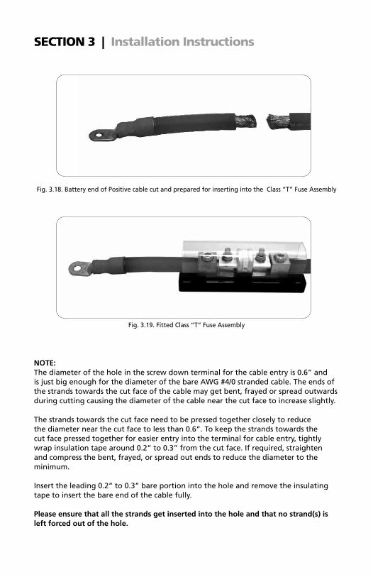
note: The diameter of the hole in the screw down terminal for the cable entry is 0.6” and is just big enough for the diameter of the bare AWG #4/0 stranded cable. The ends of the strands towards the cut face of the cable may get bent, frayed or spread outwards during cutting causing the diameter of the cable near the cut face to increase slightly.
The strands towards the cut face need to be pressed together closely to reduce the diameter near the cut face to less than 0.6”. To keep the strands towards the cut face pressed together for easier entry into the terminal for cable entry, tightly wrap insulation tape around 0.2” to 0.3” from the cut face. If required, straighten and compress the bent, frayed, or spread out ends to reduce the diameter to the minimum.
Insert the leading 0.2” to 0.3” bare portion into the hole and remove the insulating tape to insert the bare end of the cable fully. Please ensure that all the strands get inserted into the hole and that no strand(s) is left forced out of the hole.
fig. 3.18. battery end of Positive cable cut and prepared for inserting into the Class “T” fuse Assembly
fig. 3.19. fitted Class “T” fuse Assembly
sectIOn 3 | Installation Instructions
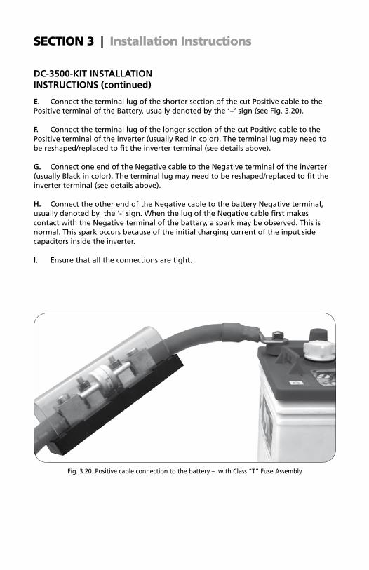
e. Connect the terminal lug of the shorter section of the cut Positive cable to the Positive terminal of the battery, usually denoted by the ‘+’ sign (see fig. 3.20).
F. Connect the terminal lug of the longer section of the cut Positive cable to the Positive terminal of the inverter (usually red in color). The terminal lug may need to be reshaped/replaced to fit the inverter terminal (see details above). G. Connect one end of the Negative cable to the Negative terminal of the inverter (usually black in color). The terminal lug may need to be reshaped/replaced to fit the inverter terminal (see details above). H. Connect the other end of the Negative cable to the battery Negative terminal, usually denoted by the ‘-’ sign. When the lug of the Negative cable first makes contact with the Negative terminal of the battery, a spark may be observed. This is normal. This spark occurs because of the initial charging current of the input side capacitors inside the inverter.
i. ensure that all the connections are tight.
fig. 3.20. Positive cable connection to the battery – with Class “T” fuse Assembly
Dc-3500-Kit inStALLAtion inStRuctionS (continued)
sectIOn 3 | Installation Instructions

12 | SAMLEX AMERICA INC.
sectIOn 4 | specifications
Model DC-1000-KIT DC-2000-KIT DC-2500-KIT DC-3500-KIT
† Cable Size AWG #4 AWG #2 AWG #2/0 AWG #4/0
Battery System Voltage
Length of Cable
RunVoltage Drop Across Cable Run
12V System 3 ft. 1.3 % 1.6 % 1.2 % 1.0 %
6 ft. 2.5 % 3.2 % 2.3 % 2.0 %
10 ft. 4.2 % 5.3 % 3.9 % 3.3 %
24V System 3 ft. 0.6 % 0.8 % 0.6 % 0.5 %
6 ft. 1.3 % 1.6 % 1.2 % 1.0 %
10 ft. 2.1 % 2.7 % 1.9 % 1.7 %
Fuse MRBF-100 100 Amp
MRBF-200 200 Amp
MRBF-300300 Amp
JLNN-400400 Amp
Hardware Included
6 Nos. 11.5” Black Tie Wraps6 Nos. 1/2” Cable clamps6 Nos. #8 x ¾” Pan head screws
6 Nos. 11.5” Black Tie Wraps6 Nos. 1/2” Cable clamps6 Nos. #8 x ¾” Pan head screws
6 Nos. 11.5” Black Tie Wraps6 Nos. 3/4” Cable clamps6 Nos. #8 x ¾” Pan head screws
6 Nos. 11.5” Black Tie Wraps6 Nos. 1” Cable clamps6 Nos. #8 x ¾” Pan head screws
Inverter Power Range
12V600-1000W
24V1200-2000W
12V1000-1700W
24V2000-3400W
12V1700-2500W
24V3400-5000W
12V2500-3500W
24V5000-7000W
note: Specifications are subject to change without notice.
See notes page 14.
† cables: - Positive and Negative Cables, 10 ft. each - Stranded Copper Conductors - Crimped ring Tongue Terminals on both ends - 600V, -50°C to 105°C
noteS• Current in Amperes a conductor can carry continuously under conditions of use
without exceeding its temperature rating is termed Ampacity (Ampere Capacity). Conductor temperature rating of 105°C / 221°f, ambient temperature of 30°C / 86°f and wiring in free air have been considered.
• Cable size is indicated in American Wire Gauge (AWG). AWG of a stranded cable is determined by the total cross-sectional area of the conductors. Because there are also small gaps between the strands, stranded cable with higher number of strands will always have a slightly larger overall diameter than a solid cable / cable with lesser number of strands with the same AWG.
• The Ampacity of the cable is equal to or greater than the DC input current at the rated continuous output power of the recommended power range of typical inverters.
• lengths of cable run of 3 ft. (.91 meters) / 6 ft. (1.83 meters) / 10 ft. (3.05 meters) are the distances between the battery and the inverter. The running length of rout-ing of the cable should be considered if the wiring run is not straight but circuitous.
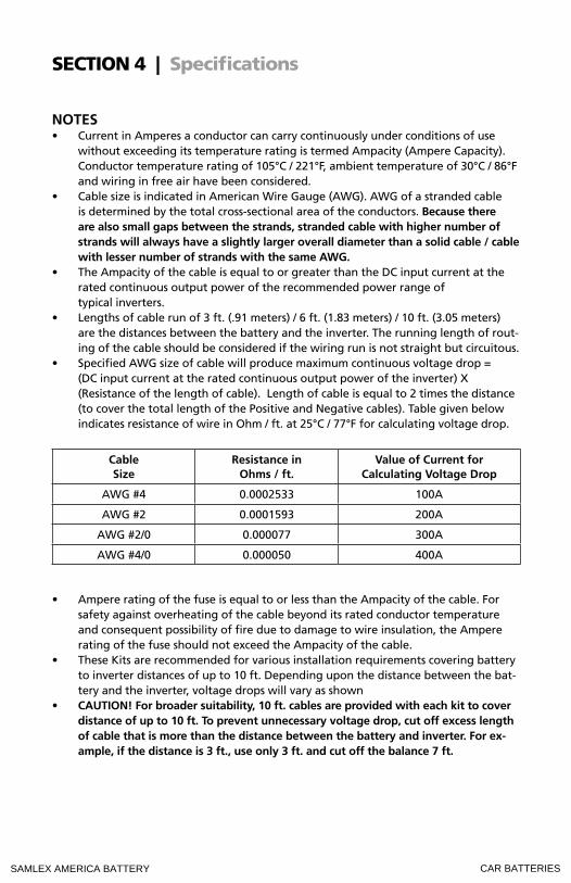
• Specified AWG size of cable will produce maximum continuous voltage drop = (DC input current at the rated continuous output power of the inverter) X (resistance of the length of cable). length of cable is equal to 2 times the distance (to cover the total length of the Positive and Negative cables). Table given below indicates resistance of wire in ohm / ft. at 25°C / 77°f for calculating voltage drop.
cable Size
Resistance in ohms / ft.
Value of current for calculating Voltage Drop
AWG #4 0.0002533 100A
AWG #2 0.0001593 200A
AWG #2/0 0.000077 300A
AWG #4/0 0.000050 400A
• Ampere rating of the fuse is equal to or less than the Ampacity of the cable. for safety against overheating of the cable beyond its rated conductor temperature and consequent possibility of fire due to damage to wire insulation, the Ampere rating of the fuse should not exceed the Ampacity of the cable.
• These Kits are recommended for various installation requirements covering battery to inverter distances of up to 10 ft. Depending upon the distance between the bat-tery and the inverter, voltage drops will vary as shown
• cAution! For broader suitability, 10 ft. cables are provided with each kit to cover distance of up to 10 ft. to prevent unnecessary voltage drop, cut off excess length of cable that is more than the distance between the battery and inverter. For ex-ample, if the distance is 3 ft., use only 3 ft. and cut off the balance 7 ft.
sectIOn 4 | specifications
*
SAMLEX AMERICA BATTERY CAR BATTERIES