investigating a semi-solid processing technique using
TRANSCRIPT

Investigating a Semi-Solid Processing technique using metal powder bed Additive
Manufacturing Processes
P. Voraa, F. Dergutib, K. Mumtaza, I. Toddb, N. Hopkinsona
a Department of Mechanical Engineering, University of Sheffield; b Department of Material Science and Engineering, University of Sheffield.
The work reported investigates in-situ alloying using a semi-solid processing technique with metal
powder bed Additive Manufacturing (AM); in this instance Selective Laser Melting (SLM) and
Electron Beam Melting (EBM) were employed. This technique utilised customised powder blends
that were processed at elevated temperatures. The selection of processing temperature considered
specific alloy solidification ranges. As a result, parts with reduced residual stresses can be produced.
In addition, the use of customised powder blends explored the feasibility of developing alloys specific
to the process/application, thus increasing available material ranges for AM metal powder bed
processes.
1 Introduction Metal powder based Additive Manufacturing (AM) technologies such as Selective Laser Melting
(SLM) also known as Direct Metal Laser Sintering (DMLS™), Electron Beam Melting (EBM) and
Direct Metal Deposition (DMD) are being increasingly adopted with research conducted to enable
processing of different materials. Extensive research and subsequent confidence in these technologies
have resulted in quality parts that are directly used in various sectors such as automotive, aerospace,
medical and other industries. Parts produced by metal AM have properties similar to parts produced
using conventional methods; and are sometimes superior.
Metal powder bed technologies such as SLM and EBM share a similar basic working principle. The
process begins with part design with computer aided design software. This 3D computer designed
model is processed, additional supports are added (if required) and sliced into a number of layers
before it is fed to the AM machine. In the machine a thin layer of metal powder is spread on a process
table (movement constrained in vertical direction only). The high intensity energy source (laser beam
in SLM and electron beam in EBM) scans and liquid phase sinters the desired area of the powder bed
based on the sliced data from the file. On completion of a scan, the process table lowers by single
layer thickness and fresh powder is spread. The beam scans the powder bed and process continues
until a complete part is build. Figure 1 illustrates schematic of SLM and EBM technologies. SLM
operates in an inert atmosphere of argon gas circulating in the processing chamber whereas the EBM
is carried out under vacuum. The build rate in SLM is comparatively slower than EBM; however
surface finish of parts produced in SLM is superior.
Figure 1 Schematic of metal powder bed AM processes; (A) Selective Laser Melting (Wehmoller et al. 2005)
and (B) Electron Beam Melting
454

In SLM/EBM due to rapid heating and cooling of melt pools residual stresses are developed. These
stresses result in consolidated layer(s) warping (bending upwards). To resist warping,
supports/anchors are melted in place; anchoring layers to the substrate plate. The accumulated stress
in the parts occasionally results in cracking or warping post separation from substrate plate. To reduce
residual stress accumulation optimisation of processing parameters and preheating is often employed
(Buchbinder D; et al. 2011a; Kruth et al. 2012). This helps to reduce the number of supports required
however it does not eliminate the need for supports/anchors completely.
Semi-Solid Processing (SSP) is a novel technique developed to reduce the effect of residual stresses in
part produced by metal powder bed AM processes. Researchers at University of Sheffield were able
to produce parts without supports/anchors and providing freedom to produce parts which were not
possible earlier as shown in Figure 2 (Mumtaz et al. 2011). The process began by mixing batches of
custom elemental or pre-alloyed powders such that when melted together under laser or electron
beam(s) would form an in-situ alloy in the powder bed. The alloy formed will have a wide
solidification temperature that is lower than the respective parent materials. The complete SSP
processing in SLM/ EBM was performed at elevated temperature; temperature selection was based on
the solidification range of the respective in-situ alloy formed. Therefore the processed material
remained in liquid-solid mushy state until the complete part was build and allowed to cool down. The
selection of optimum elevated temperature resulted in minimum residual stress being induced during
solidification.
Figure 2 SLM parts produced with SSP (Material: Bi3Zn) (Mumtaz et al. 2011).
Several studies have looked at processing new materials, improving process capabilities and part
properties. Different materials such as Aluminium alloys, titanium alloys, stainless steel, nickel alloys,
and others are used to produce parts (Das 1998; Brinksmeier et al. 2010; Kruth et al. 2012; Sun et al.
2013). The desire to process aluminium and its alloys using metal powder bed AM processes has been
well known (Louvis et al. 2011). Several studies have been published on processing cast and wrought
aluminium alloys systems such as Al-Si, Al-Si-Mg, Al-Cu-Mg and Al-Mg-Zn (Buchbinder D. et al.
2011b; Louvis et al. 2011; Dadbakhsh et al. 2012). Common issues observed in processing aluminium
with SLM were insufficient wetting of melt pool, high reflectively of aluminium powders, aluminium
oxide causing degradation of part properties, etc. (Louvis et al. 2011).
Another high interest metallic alloy has been titanium and its alloys. Ti6Al4V (also known as Ti64)
has been processed using SLM/EBM and widely used in aerospace and medical industry due to better
mechanical properties and bio compatibility of the material (Li et al. 2006; Thijs et al. 2010). Like
other metallic materials, warping in EBM is a common issue. Therefore the semi-solid processing
method was tried using EBM with a custom metal powder mix. Previously attempts made to process
Ti64 using EBM to benchmark unsupported overhanging features capability and unsupported features
warped (Vora et al. 2012). A maximum of 2.7mm of warp height was measured for 5mm long and
2mm thick unsupported overhang geometry. Figure 3 shows warped geometry and corresponding
warp height.
Z
X
Y
455

Figure 3 Benchmarking unsupported overhang capabilities with Ti64 in EBM; 2mm thick overhang geometries.
The metal powders used in AM are commercially pure or occasionally a blend of powders (metallic
and/or non-metallic) whereas most are used in form of pre-alloyed powders. These pre-alloyed
metallic powders were traditionally designed for conventional powder based manufacturing process or
casting. However these powders are occasionally found unfavourable for AM processes due to the
non-equilibrium conditions during processing (rapid solidification phenomena) in metal AM,
therefore affecting part properties and/or leading to in-processing issues in AM. Therefore it is
required to develop optimised alloys in powder form for metal AM processes. Custom powder blends
can be mixed and in-situ alloyed using SLM/EBM. Previous studies undertaken by Bartkowiak et al.
(2011) and Sanz-Guerrero et al. (2008) investigated feasibility of developing in-situ alloying of Al-
Cu / Al-Zn and Ti-Cu powder systems in SLM respectively. Both the studies showed potential in
developing in-situ alloys under laser. In addition to the semi-solid processing, this work investigated
in-situ alloying of elemental powder blends that can be used to design optimised alloys for SLM and
EBM. This would result in faster development of materials that will satisfy industry demands and also
be a cost effective approach allowing simpler supply chains for many material variants.
2 Experimental Setup and Methods
2.1 Powders Processed The purpose of the study was to understand SSP using SLM and EBM. The new developed hardware
for SLM and the EBM characteristic pre-heating themes motivated to compare both processes. A
direct comparison between both the processes using same material would have been ideal. However
due to health and safety issues on SLM for using titanium alloys and limitation on materials allowed
to process on EBM at University of Sheffield, two different material system were selected. Al-Si
eutectic system was processed on SLM and Ti64-Cu system on EBM machine.
Aluminium and Silicon powders were melted to perform in-situ alloying in SLM machine. The pure
aluminium powder was a gas atomised powder with near to spherical morphology. The particle size
distribution was in the range was 20-45µm. Pure silicon powder obtained was not gas atomised and
thus had an irregular morphology. The as purchased powder had a wide particle size distribution;
therefore the range was reduced by sieving (-45µm). Both the powders were mixed in a ratio of 88%
by wt. of aluminium and 12% by wt. of silicon to effectively form a eutectic alloy; AlSi12 after laser
processing. Ti64 and Cu were gas atomised powders with particle size range of 50-110µm. The
powders were blended in a ratio of Ti64-90% by wt. and Cu - 10% by wt.
456
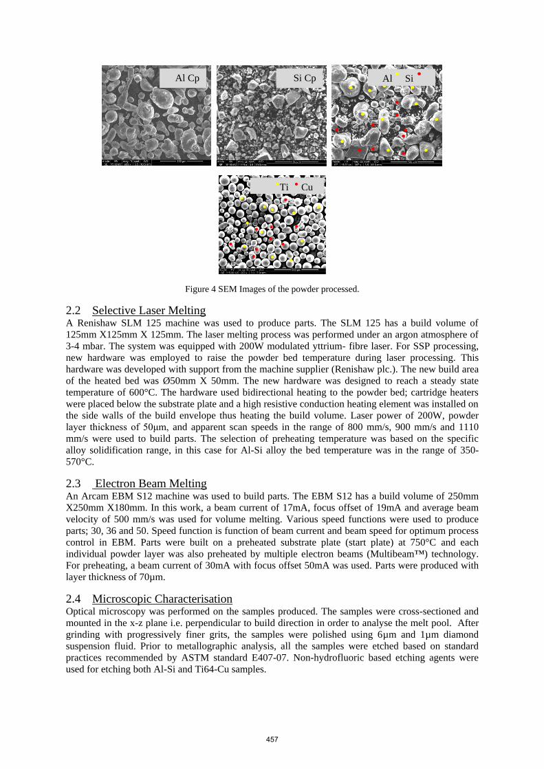
Figure 4 SEM Images of the powder processed.
2.2 Selective Laser Melting A Renishaw SLM 125 machine was used to produce parts. The SLM 125 has a build volume of
125mm X125mm X 125mm. The laser melting process was performed under an argon atmosphere of
3-4 mbar. The system was equipped with 200W modulated yttrium- fibre laser. For SSP processing,
new hardware was employed to raise the powder bed temperature during laser processing. This
hardware was developed with support from the machine supplier (Renishaw plc.). The new build area
of the heated bed was Ø50mm X 50mm. The new hardware was designed to reach a steady state
temperature of 600°C. The hardware used bidirectional heating to the powder bed; cartridge heaters
were placed below the substrate plate and a high resistive conduction heating element was installed on
the side walls of the build envelope thus heating the build volume. Laser power of 200W, powder
layer thickness of 50μm, and apparent scan speeds in the range of 800 mm/s, 900 mm/s and 1110
mm/s were used to build parts. The selection of preheating temperature was based on the specific
alloy solidification range, in this case for Al-Si alloy the bed temperature was in the range of 350-
570°C.
2.3 Electron Beam Melting An Arcam EBM S12 machine was used to build parts. The EBM S12 has a build volume of 250mm
X250mm X180mm. In this work, a beam current of 17mA, focus offset of 19mA and average beam
velocity of 500 mm/s was used for volume melting. Various speed functions were used to produce
parts; 30, 36 and 50. Speed function is function of beam current and beam speed for optimum process
control in EBM. Parts were built on a preheated substrate plate (start plate) at 750°C and each
individual powder layer was also preheated by multiple electron beams (Multibeam™) technology.
For preheating, a beam current of 30mA with focus offset 50mA was used. Parts were produced with
layer thickness of 70µm.
2.4 Microscopic Characterisation Optical microscopy was performed on the samples produced. The samples were cross-sectioned and
mounted in the x-z plane i.e. perpendicular to build direction in order to analyse the melt pool. After
grinding with progressively finer grits, the samples were polished using 6µm and 1µm diamond
suspension fluid. Prior to metallographic analysis, all the samples were etched based on standard
practices recommended by ASTM standard E407-07. Non-hydrofluoric based etching agents were
used for etching both Al-Si and Ti64-Cu samples.
Al Si Al Cp Si Cp
Ti Cu
457

2.5 Part design Figure 5 shows the part geometry produced. ‘T’ geometries were manufactured with overhanging
feature length in the range of 2-5 mm. To compare the effect of residual stresses in ‘T’ geometries,
one side was supported and other was unsupported. Based on the previous benchmarking study (Vora
et al. 2012), a clear visible warping was observed in geometries with 2mm thick overhangs. Therefore
2mm thick overhangs were considered for the purpose of this study.
Figure 5 Supported and unsupported ‘T’ geometry for SSP with SLM and EBM processing.
3 Results and Discussion
3.1 Parts Produced Figure 6 shows parts produced with SSP processing technique using SLM and EBM. This length of
unsupported feature would typically warp without supports causing process failure. Processing with
SSP allowed the production of complete overhanging features with reduced or negligible warp. As
seen in Figure 6 (A and B) flat top surfaces of the parts were obtained.
Figure 6 Parts produced by SLM and EBM- SSP processing
Due to irregular deposition of powder and poor powder flow properties of Al-Si powders, a poor
surface finish was obtained on SLM parts. The irregular morphology of silicon powder further
reduced flow properties of the blended powder. In parts produced by EBM, poor edge retention was
observed on unsupported overhang. Buchbinder D; et al. (2011a) observed similar poor edge retention
in ‘T’ geometries produced with AlSi10Mg in SLM. It was suggested this could be due to shrinkage
of the first layer and then shrinkage progressively reducing over the thickness and resistance from
previously consolidated layers. The higher shrinkage in first layer could be result of freedom of
movement because of the absence of supports. However by employing the SSP technique, the
shrinkage in layer did not cause layer to warp. This could be improved by raising the bed temperature
to further reduce shrinkage and stress formation.
3.2 Metallographic Analysis Figure 7 shows a micrograph of in-situ alloyed AlSi12 processed with SLM. A dendritic structure can
be seen which is typical of aluminium-silicon system. The white structures (dendrites) are aluminium
Supported Unsupported Unsupported
(A) Al-12Si (1100mm/s) (B) Ti6Al4V-10Cu (Speed function 50)
Z
Z Z
2mm
5mm overhang
458

solid solution and the darker regions are Al-Si eutectics or silicon. Due to rapid solidification, SLM
shows finer structures. It can be seen the dendrites in a few areas are coarse, suggesting slow cooing.
However the eutectic structure seems to be reasonably uniform, suggesting successful in-situ alloying
of Al-Si powders.
Figure 7 Microstructure of in-situ alloyed AlSi12 processed with SLM
Figure 8 shows the microstructure of Ti64-10Cu processed with EBM. It is well known that titanium
undergoes allotropic phase transformation when heated up to 882°C. A similar transformed
microstructure of acicular α-Ti (needle like structures) from the grain boundaries of β-Ti can be seen.
A unique spread of red colour microstructure was observed. The colour suggested a Cu rich phase.
Further analysis using Energy Dispersive X-ray spectroscopy (EDX) would help verify the
hypothesis.
Figure 8 Microstructure of in-situ alloyed Ti64-10Cu processed with EBM
3.3 Effect of residual stress (by visual method- warp measurement) Figure 9 shows a plot of warp measurement of in-situ alloyed AlSi12 processed by SSP technique
with SLM. The parts showed no warp on the unsupported edges. The parts were built at an elevated
temperature of ~380°C. The SLM parts produced at scan speed of 1110 mm/s had high part density of
91% compared to other scan speeds.
Defects
459

Figure 9 Warp measurement of in-situ alloyed Al-12Si samples produced by SLM
Figure 10 shows a plot of warp measurement of Ti64 and in-situ alloyed Ti64-10Cu samples produced
by EBM. 2.7mm warp was measured in an unsupported overhang feature (5mm long and 2 mm thick)
produced by Ti64. The SSP processed Ti64-Cu overhangs showed a maximum of warp height of 0.4
for a 5mm long unsupported feature and the minimum of 0.3mm was measured. The minimum warp
height of unsupported feature was observed in part with higher scan speed.
Figure 10 Warp measurement of in-situ alloyed Ti64-10Cu samples produced by EBM
The faster scan speed enabled control of the size of melt pool of the in-situ formed alloy. Compared to
Ti64, the addition of copper increased the freezing range; which was also directly proportional to
copper concentration. Thus the alloy exists in a liquid-solid mushy state over a wide range of
temperature (Dahle et al. 1998) thus acting as a stress reducer and producing parts without
substantially reduced warping.
4 Conclusions and Further Work Al-Si and Ti64-Cu alloy systems were successfully processed and alloyed in-situ using Semi-Solid
Processing technique within the SLM and EBM equipment. Unsupported overhang geometries of
460
5mm were built without warping, which we believe has never been achieved before. This work
demonstrated new capabilities of SLM and EBM processes to build parts without supports using the
blended powder approach. The SLM parts showed no signs of warping. Compared to benchmarking
results with Ti64 on EBM, warp height was found reduced by 88% from 2.7mm to 0.3mm. Further
analysis and optimisation work will be performed on parts produced. Work in areas of parameter
optimisation to obtain optimum density and better surface finish, analysis on mechanical properties of
parts and residual stress analysis will be conducted. This work also demonstrated new capabilities of
SLM system to process material at higher temperature (up to 600°C) using the developed heated bed
hardware. New materials will be designed and processed using SSP technique. In addition multi-layer
parts with blended powders were manufactured. This shows the possibility of in-situ alloying of
powder systems in SLM and EBM, therefore demonstrating a new approach in developing new
materials quicker and optimised for metal powder bed AM processes.
5 References
Bartkowiak, et al. (2011), "New Developments of Laser Processing Aluminium Alloys via
Additive Manufacturing Technique." Lasers in Manufacturing 2011: Proceedings of
the Sixth International Wlt Conference on Lasers in Manufacturing, Vol 12, Pt A, 12,
393-401, Issn: 1875-3892.
Brinksmeier, et al. (2010), "Surface integrity of selective-laser-melted components." Cirp
Annals-Manufacturing Technology, 59(1), 601-606, Issn: 0007-8506.
Buchbinder, et al. (2011a), "Investigation to reduce the delay by preheating in the production
of aluminum parts using SLM." RTejounal- Forum for Rapid technology, Vol 8, Issn:
urn:nbn:de:00009-2-31583.
Buchbinder, et al. (2011b), "High Power Selective Laser Melting (HP SLM) of Aluminum
Parts." Physics Procedia, 12, Part A(0), 271-278, Issn: 1875-3892.
Dadbakhsh, et al. (2012), "Effect of Al alloys on selective laser melting behaviour and
microstructure of in situ formed particle reinforced composites." Journal of Alloys
and Compounds, 541(0), 328-334, Issn: 0925-8388.
Dahle, et al. (1998), "Rheological behaviour of the mushy zone and its effect on the
formation of casting defects during solidification." Acta Materialia, 47(1), 31-41,
Issn: 1359-6454.
Das. (1998), "Direct selective laser sintering of high performance metals: Machine design,
process development and process control", The University of Texas at Austin, The
University of Texas at Austin.
Kruth, et al. (2012), "Assessing and comparing influencing factors of residual stresses in
selective laser melting using a novel analysis method." Proceedings of the Institution
of Mechanical Engineers, Part B: Journal of Engineering Manufacture, Issn.
Li, et al. (2006), "Porous Ti6Al4V scaffold directly fabricating by rapid prototyping:
preparation and in vitro experiment." Biomaterials, 27(8), 1223-1235, Issn: 0142-
9612.
Louvis, et al. (2011), "Selective laser melting of aluminium components." Journal of
Materials Processing Technology, 211(2), 275-284, Issn: 0924-0136.
Mumtaz, et al. (2011), "A method to eliminate anchors/supports from directly laser melted
metal powder bed processes", Presented at Solid Freeform Fabrication, Texas,
University of Texas.
Sanz-Guerrero, et al. (2008), "Effect of total applied energy density on the densification of
copper–titanium slabs produced by a DMLF process." Journal of Materials Processing
Technology, 202(1–3), 339-346, Issn: 0924-0136.
461

Sun, et al. (2013), "Parametric optimization of selective laser melting for forming Ti6Al4V
samples by Taguchi method." Optics & Laser Technology, 49(0), 118-124, Issn:
0030-3992.
Thijs, et al. (2010), "A study of the microstructural evolution during selective laser melting of
Ti–6Al–4V." Acta Materialia, 58(9), 3303-3312, Issn: 1359-6454.
Vora, et al. (2012), "Benchmarking capabilities of SLM and EBM to build overhangs without
supports", Presented at Twenty Third Annual International Solid Freeform
Fabrication Symposium – An Additive Manufacturing Conference Texas,
Wehmoller, et al. (2005), "Implant design and production - a new approach by selective laser
melting." CARS 2005: Computer Assisted Radiology and Surgery, 1281, 690-695,
Issn: 0531-5131.
462