investigation and design - british...
TRANSCRIPT


.1
INVESTIGATION AND DESIGN
OF MINE DUMPS
INTERIM GUIDELINES
Prepared for the:
British Columbia Mine Dump Committee with funding provided from the Provincial Sustainable Environment Fund
Prepared by:
Piteau Associates Engineering Ltd. 215 • 260 West Esplanade North Vancouver, B.C. V7M 3G7
MAY 1991

Canadian cataloguing in Publication Data Main entry under title: Investigation & design of mine dumps
Includes bibliographical references: p. ISBN 0-7718-9118-0
1. Coal mines and m1n1ng - waste disposal - British Columbia. 2. coal mines and mining - waste disposal - Environmental aspects - British Columbia. 3. Mineral industries - waste disposal - British Columbia. 4. Mineral industries - waste disposal Environmental aspects - British Columbia. I. British Columbia Mine Dump Committee. II. Piteau Engineering Ltd. III. British Columbia. Ministry of Energy, Mines and Petroleum Resources.
TD899.M5158 1991 622'.334 C91-092314-0

FOREWORD
Mine waste rock and overburden dumps are massive structures, for example, mountain top coal mines in British Columbia are constructing the largest man-made structures on the face of the earth. These immense waste dumps are often up to 400 meters high, designed to contain in excess of 1 billion cubic meters of material and often form mid-valley fills or rock drains. Instability of the structures has caused increased concern by the mine operators and the government regulators because of impacts on the environment and risk to the safety of personnel, equipment and infrastructure.
In mid 199 0 representatives of industry, CANMET and the ministries of Environment and Energy, Mines and Petroleum Resources formed a committee to foster research work and ensure a common understanding of these waste dumps.
These Interim Guidelines form one of a series of studies undertaken by the committee. Prominent geotechnical consultants and industry representatives have reviewed the guide and many of their suggestions have been incorporated.
I would like to stress that this document is purely for guidance and to assist in developing a standardization of approach in pre-design investigation and also in design analysis.
Over the course of the next year it is the intent of the committee to evaluate and verify the innovative classification system developed by the authors and also to encourage constructive comment from industry, regulatory personnel and consultants. In early 1990 the committee is proposing to sponsor a series of workshops to introduce all of the studies to key industry personnel and capture the practical experience of a year of using the guidelines so that a planned rewrite can incorporate that experience.
The guidelines are being widely distributed by the Ministry of Energy, Mines and Petroleum Resources in the hopes that all concerned with mine dumps will find them useful in establishing dumps that are stable, safe and economically feasible, as well as to solicit your comments.
R.W. McGinn, P.Eng. Chairman, Waste Dump Research Committee May 21, 1991

i.
EXECUTIVE SUMMARY
INTRODUCTION
This report presents the results of a study commissioned by the B.C. Ministry of
Energy, Mines and Petroleum Resources to review the current practice and develop
practical guidelines for geotechnical investigation, analysis and design of mine
dumps in British Columbia. It is recognized that environmental, land use and
related issues must also be addressed in the investigation and design process;
particularly in view of the potential impact that mine dump instability may have
on the environment. However, the primary focus of this study is the
geotechnical stability of mine dumps. Where preliminary investigations indicate
that serious environmental impacts could occur, such as acid rock drainage,
runout of failures into sensitive habitats, impacts to private or public lands
or facilities, etc., detailed, focussed assessments of these aspects will also
be necessary.
Results of this study are presented as an interim working document. Certain
aspects of the study will be subject to review and revision as new conditions or
technology comes to light, or as new legislation is enacted. In particular,
verification and calibration of the mine dump classification scheme proposed in
Section 5 is required before it can be finalized and adopted for widespread use.
A revised document will be prepared in due course, and periodically updated.
As part of the study, a survey of dumps at 31 active mines in the province was
undertaken, and synopses on 83 individual dumps were prepared and are given in
Appendix A. Contributions to the guide were solicited from mine operators,
regulatory agencies, research and industry groups and geotechnical consultants.
Much relevant information has been abstracted from the literature, and an
annotated bibliography is provided in Section 9.
This guide has been developed to meet the needs of a wide range of interests
throughout the mining industry, including those of mine proponents, regulators

ii.
and consultants. Individual sections of the guide address pertinent aspects of
the investigation, analysis and design procedure as described in the following.
PLANNING
Section 2 reviews the current regulatory requirements for mine dump development
in B.C. A recommended investigation, analysis and design procedure which
complements the current Mine Development Review Process (MDRP) is described and
illustrated in a series of flow charts. Factors which must be considered in the
design process are classified into five basic categories: Mining Factors,
Physical Constraints,__Environmental Impacts, Stability and Socio-Political
Considerations.
SITE CHARACTERIZATION AND FIELD STUDIES
Section 3 describes the range of site investigation studies required to define
the physical characteristics of a proposed dump site. Six areas of study are
recognized: Physiography and Geomorphology, Hydrology and Climate, Bedrock
Geology and Tectonics, Surficial Geology and Soils, Hydrology, and Environment
and Culture. For each of these study areas, key characteristics are identified,
and their implication in site selection and design, sources of available
information and field methods for obtaining the relevant data are described.
MATERIAL PROPERTIES AND TESTING
The important physical and geochemical properties of the bedrock and soils in
the dump foundation, and mine rock and overburden materials used to construct
the dump, and their application in the design process are described in Section
4. In situ and laboratory techniques for defining the various properties are
also described. In addition, recommendations for baseline surface water and
groundwater quality sampling and testing are given.

iii.
MINE DUMP CLASSIFICATION
Section 5 reviews the various factors which influence dump stability and
presents a comprehensive stability rating and classification scheme. Dump
Stability Ratings (DSR) and Classes (DSC) provide a semi-quantitative measure of
the complexity and hazard of a given dump configuration. They may be used to
compare alternative dump configurations and sites, and provide an indication of
the relative level of effort which should be applied throughout the
investigation and design process. Recommendations regarding the level of
effort, and two examples illustrating the classification system are given. A
discussion of the various risks associated with dump development is also
included.
STABILITY ANALYSIS
Possible modes of dump failure and key factors which could contribute to each
mode are described in Section 6. In addition, alternative analysis techniques
and their advantages and limitations are described and referenced. Factor of
Safety and Probabilistic approaches to evaluating stability analysis results are
presented. Interim guidelines for minimum design factor of safety are also
given.
CONSTRUCTION
Section 7 reviews various aspects of mine dump construction and development
which should be considered during the design process. Various alternatives for
foundation preparation, control of surface water, snow control, construction
methods, and possible hazard mitigation measures are described. The importance
of considering reclamation objectives in the initial design process, and
updating the design based on documented performance is also discussed.

1
CONTENTS
1. INTRODUCTION
1.1 GENERAL 1 1.1.1 Background ~
1.1.2 Study Objectives 1 1.1.3 Scope of Guidelines 2 1.1.4 Terms of Reference 3
1.2 RELATED STUDIES 3 1.2.1 Operation and Monitoring of Mine Dumps
- Interim Guidelines 4 1.2.2 Major Mine Dump Failures 4 1.2.3 Runout Analysis 4 1.2.4 Mine Dump Monitoring 4
1.3 MINE DUMP SURVEY 5 1.4 CONSULTATIONS WITH INDUSTRY AND REGULATORS 5 1.5 LITERATURE REVIEW 6 1.6 PROJECT PERSONNEL 7
2. PLANNING 8
2.1 MINE DEVELOPMENT REVIEW PROCESS 8 2.2 RECOMMENDED DESIGN SEQUENCE 10
2.2.1 Exploration 10 2.2.2 Prefeasibility 10 2.2.3 Feasibility and Preliminary Design 14 2.2.4 Detailed Geotechnical Studies 16
2.3 BASIC DESIGN CONSIDERATIONS 17 2.3.1 Mining Factors 17 2.3.2 Physical Constraints 17 2.3.3 Environmental Impact 18 2.3.4 Short and Long Term Stability 18 2.3.5 Social/Political Considerations 18
3. SITE CHARACTERIZATION AND FIELD STUDIES 19
3.1 GENERAL 19 3.2 PHYSIOGRAPHY AND GEOMORPHOLOGY 21 3.3 HYDROLOGY AND CLIMATE 22 3.4 BEDROCK GEOLOGY AND TECTONICS 23 3.5 SURFICIAL GEOLOGY AND SOILS 24 3.6 HYDROGEOLOGY 25 3.7 ENVIRONMENT AND CULTURE 27

CONTENTS (cont'd.)
4. MATERIAL PROPERTIES AND TESTING 29
4.1. GENERAL 29 4.2 FOUNDATION SOILS 29
4.2.1 Description 31 4.2.2 Index Properties and Classification 31 4.2.3 Hydraulic Conductivity 33 4.2.4 Consolidation 34 4.2.5 Strength 35 4.2.6 Mineralogy and Soil Chemistry 36 4.2.7 In Situ Density 37 4.2.8 Compaction 37
4.3 FOUNDATION BEDROCK 37 4.3.1 Description 38 4.3.2 Strength 38 4.3.3 Mineralogy and Petrography 40 4.3.4 Durability 40 4.3.5 Hydraulic Conductivity 41
4.4 MINE ROCK 41 4.4.1 Description 43 4.4.2 Bulk Gradation 44 4.4.3 Plasticity of Fines 46 4.4.4 Intact Strength 46 4.4.5 Shear Strength 46 4.4.6 Mineralogy and Petrography 49 4.4.7 Durability 49 4.4.8 Hydraulic Conductivity 50 4.4.9 Consolidation and Settlement 50 4.4.10 Geochemistry 51
4 . 5 OVERBURDEN 51 4.5.1 Description, Index Properties and Classification 52 4.5.2 Hydraulic Conductivity 52 4.5.3 Strength 54 4.5.4 Density 54 4.5.5 Mineralogy and Soil Chemistry 54
4.6 WATER QUALITY 55
5. MINE DUMP CLASSIFICATION 57
5.1 MINE DUMP DESCRIPTION 57 5.1.1 Valley Fills 59 5.1.2 Cross-Valley Fills 59 5.1.3 Sidehill Fills 60 5.1.4 Ridge Crest Fills 60 5.1.5 Heaped Fills 60 5.1.6 Other Fills 60

CONTENTS (cont'd.)
5.2 FACTORS AFFECTING DUMP STABILITY 61 5.2.1 Dump Configuration 61 5.2.2 Foundation Slope and Degree of Confinement 62 5.2.3 Foundation Conditions 62 5.2.4 Dump Material Properties 63 5.2.5 Method of Construction 63 5.2.6 Piezometric and Climatic Conditions 64 5.2.7 Dumping Rate 65 5.2.8 Seismicity and Dynamic Stability 66
5.3 CLASSIFICATION SCHEME 66 5.3.1 Dump Stability Rating 66 5.3.2 Dump Stability Class 69 5.3.3 Application to the Design Process 69 5.3.4 Examples 71
5.4 ASSESSMENT OF RISK 73 5.4.1 Safety of Personnel and Equipment 74 5.4.2 Risk to Facilities 75 5.4.3 Environmental Risk 75
6. STABILITY ANALYSIS 77
6.1 FAILURE MODES 77 6.2 EMBANKMENT FAILURES 77
6.2.1 Edge Slumping 77 6.2.2 Plane Failure 80 6.2.3 Rotational Failure 81 6.2.4 Flows 81
6.3 BASE FAILURES 82 6.3.1 Rotational Failure 82 6.3.2 Non-Circular Rotational Failure 82 6.3.3 Wedge Failure 83 6.3.4 Base Translation 83 6.3.5 Liquefaction 83 6.3.6 Toe Failure 84
6.4 ANALYSIS METHODS 84 6.4.1 Total Stress vs. Effective Stress 89 6.4.2 Stability Charts 90 6.4.3 Infinite Slope Analysis 90 6.4.4 Plane Failure Analysis 91 6.4.5 Wedge Failure Analysis 91 6.4.6 Slip Circle Analysis 92 6.4.7 Methods of Slices 93 6.4.8 Y=O Method 95 6.4.9 Numerical Methods 95 6.4.10 Liquefaction Analysis 96 6.4.11 Dynamic Stability Analysis 96

CONTENTS (cont'd.)
6.5 INTERPRETATION OF STABILITY ANALYSIS RESULTS 6.5.1 Factor of Safety 6.5.2 Probability of Failure
6.6 SETTLEMENT 6.7 FAILURE RUNOUT
7. CONSTRUCTION
7.1 FOUNDATION PREPARATION 7.1.1 Clearing 7.1. 2 Stripping 7.1.3 Underdrainage 7.1.4 Prelifts
7.2 SURFACE WATER AND SNOW CONTROL 7.2.1 Diversions and Runoff Control 7.2.2 Flow-Through Rock Drains 7.2.3 Snow Control
7.3 CONSTRUCTION METHODS 7.3.1 Platforms and Lifts 7.3.2 Ascending vs. Descending Construction 7.3.3 Material Distribution and Crest Advancement 7.3.4 Topographic Factors 7.3.5 Terraces and Wrap-Arounds 7.3.6 Buttresses and Impact Berms 7.3.7 Control of Material Quality 7.3.8 Winter Construction 7.3.9 Restricted Operation 7.3.10 Trial Dumping
7.4 DESIGNING FOR RECLAMATION 7.5 UPDATING DESIGN BASED ON PERFORMANCE
8. ACKNOWLEDGEMENTS
9. ANNOTATED BIBLIOGRAPHY
APPENDIX A BRITISH COLUMBIA MINE DUMP SURVEY
98 98 99
101 101
102
102 102 103 103 104
104 104 105 107
108 108 108 110 111 111 113 114 116 116 116
117 118
119
120
SECTION I:
SECTION II:
SECTION III:
SECTION IV:
SECTION V:
General Information and Characteristics of Dump Materials
Dump Configuration
Foundation Conditions and Design
Development and Operation
Monitoring and Stability History

FIGURES
Fig. Page
2.1 Mine Development Review Process 9
2.2 Recommended Mine Dump Investigation and Design Sequence - Exploration and Pre feasibility 11
2.3 Recommended Mine Dump Investigation and Design Sequence - Feasibility/Preliminary Design (Stage I) 12
2.4 Recommended Mine Dump Investigation and Design Sequence - Detailed Studies/Permitting
5.1 Basic Mine Dump Types
7.1 Ascending vs Descending Construction
7.2 Recommended Sequence for Advancement of Dumps Steep Terrain
7.3 Toe Buttress and Impact Berms
13
58
109
Over 112
115

TABLES
TABLE Page
3.1 Site Characterization and Field Methods 20
4.1 Material Properties and Testing for Foundation Soils 30
4.2 Material Properties and Testing for Foundation Bedrock 39
4.3 Material Properties and Testing for Mine Rock 42
4.4 Material Properties and Testing for Overburden 53
4.5 Baseline Surface Water and Groundwater Quality Testing 56
5.1 Dump Stability Rating Scheme 67
5.2 Dump Stability Classes and Recommended Level of Effort 70
5.3 Examples of Mine Dump Classification 72
6.1 Modes of Mine Dump Instability - Embankment Failures 78
6.2 Modes of Mine Dump Instability - Base and Foundation Failures 79
6.3 Dunp Stability Analysis Method 85
6.4 Interim Guidelines for Minimum Design Factor of Safety 100

1.
1. INTRODUCTION
1.1 GENERAL
1.1.1 Background
Disposal of mine rock and overburden is a very important, and sometimes
critical, aspect of mine development in British Columbia. Rock and
overburden dumps at some open pit mines in B.C. are amongst the largest
man-made structures on earth. Costs associated with mine rock and
overburden disposal can account for a substantial portion of a mine's
development, operation and reclamation expenditures. Equally important
are the immediate and long-term effects that mine dumps may have on the
physical environment.
Since the early 1970's, development of large surface coal mines has
resulted in a significant increase in the number and size of mine dumps in
British Columbia. Golder Associates (1987) has reported a corresponding
increase in the incidence of mine dump instability. This trend towards
more frequent and larger dump failures, and a general increase in
environmental awareness, has given rise to concerns about the safety and
environmental consequences of mine dumps, both during mining and following
mine closure.
1.1.2 Study Objectives
Current legislation in B.C. (Mines Act, S.B.C. 1989, C.56) requires that
plans and designs for proposed mine dumps (or for significant
modifications to existing or approved dumps) be submitted to the B.C.
Ministry of Energy Mines and Petroleum Resources (MEMPR) for approval
prior to issuance of a permit and commencement of mining. While
geotechnical design is a component of most new major dump plans, no
standardized approach to investigation and design currently exists. Also,

2.
the expectations of regulators regarding the level of effort and content
of submissions have not been well defined.
The purpose of this study is to review and summarize the state-of-the-art
and current practice, and develop practical guidelines for geotechnical
investigation, analysis and design of mine dumps in B.C. Where
appropriate, reference is made to environmental, land use and related
issues; however, the primary focus on this study is the geotechnical
stability of mine dumps.
It is envisaged that the results of this study will be used by mine
proponents to help them determine the various steps to be taken, and the
appropriate level of effort which should be allocated to geotechnical
investigation and design for proposed mine dumps. Study results will also
assist regulators when reviewing and adjudicating submissions.
Results of this study are presented as an interim working document.
Certain aspects of the study will be subject to review and revision as new
conditions or technology come to light, or as new legislation is enacted.
In particular, verification and calibration of the dump classification
scheme proposed in Section 5 will be conducted. In addition, it is
envisaged that periodically updated versions of this document will be
produced which incorporate the results of the classification scheme
verification/calibration, as well as results of other ongoing or future
studies.
1.1.3 Scope of Guidelines
It is recognized that each site and proposed dump are unique, and that
specific conditions may dictate a wide range of geotechnical investigation
or design requirements. While the guidelines proposed in this report have
been developed to cover a wide range of conditions, it is impractical to
consider all possible situations. Scenarios may arise in which the
guidelines conflict or are inadequate. This guide is not intended as a

3.
detailed design manual, nor should it be used as a substitute for
experienced engineering judgement.
This guide is intended to cover soft rock, hard rock and overburden dumps
for open pit and underground mines. As virtually all of the active mine
dumps in B.C. are being constructed using haul trucks and bulldozers, the
guidelines proposed herein have been developed primarily for dumps
constructed using this type of equipment. Although many of the
investigation and design principles may be similar, caution is advised
when extending the guidelines to cover other methods of dump construction,
such as dragline or bucket wheel/conveyor spoiling.
It is recognized that environmental and related aspects may influence, and
in some cases control, investigation and design requirements for mine
dumps. Where preliminary investigations indicate that serious
environmental impacts could occur, such as acid rock drainage, runout of
failures into sensitive habitats, impacts to public or private lands or
facilities, etc., detailed, focussed assessments of these aspects will be
necessary, in conjunction with geotechnical evaluations.
1.1.4 Terms of Reference
Terms of reference for the study were outlined in a Request For Proposal
issued in July 1990 by the B.C. Mine Dump Committee (BCMDC), under the
auspices of MEMPR. A contract to conduct the study was awarded to Piteau
Associates Engineering Ltd. in August 1990. A draft report was issued for
review by BCMDC and selected technical reviewers from industry,
consultants and regulators in February 1991. This interim guide was
issued in May 1991. Funding for the study was provided by MEMPR.
1.2 RELATED STUDIES
Several other related studies are currently being conducted.

4.
1.2.1 Operation and Monitoring of Mine Dumps - Interim Guidelines
A technical guide for operation and monitoring of mine dumps in B.C. is
currently being prepared by Klohn Leonoff Ltd., under contract to MEMPR.
Completion of this study and preparation of an interim working document is
also expected by May 1991. The Operation and Monitoring Guidelines are
intended to sere as a companion document for the Investigation and Design
Guidelines. Funding has been provided by MEMPR.
1.2.2 Major Mine Dump Failures
A review of major mine dump failures in B.C. and creation of a data base
is being conducted by Mr. S. Broughton, P.Eng. as part of a Master of
Engineering program in the Department of Mining and Mineral Processing at
the University of British Columbia. Funding for this study is being
partially provided by MEMPR, and results are expected by August 1991.
Results of this study will be incorporated into an updated version of the
Investigation and Design Guidelines.
1.2.3 Runout Analysis
In December 1990, Energy, Mines and Resources Canada (EMRC) requested
proposals for a study of "Runout Characteristics Of Debris From Dump
Failures In Mountainous Terrain". This study was awarded to Golder
Associates, and the anticipated completion date is March 1992.
1.2.4 Mine Dump Monitoring
EMRC also requested proposals for a review of "Monitoring Technology For
Waste Dumps In Mountainous Terrain". This study was awarded to Hardy BBT
Ltd., and was completed in April 1991.

5.
1.3 MINE DUMP SURVEY
As part of the study, a survey of mine dumps at most active mines in British
Columbia was carried out. The main objectives of this survey were to document
the current practice for investigating and designing mine dumps, and establish
the range of dump types and construction strategies in current use in B.C.
Questionnaires regarding the configuration and history of current and previous
mine dumps were sent to 21 active mine operators in B.C., representing 31
different mines. Completed or partially completed questionnaires were received
for 83 separate mine dumps, which represented a wide range of sizes and types.
Synopses of each of the dumps surveyed were prepared and compiled into a
readable spread sheet data base, which is included as Appendix A to this report.
Due to the large number and variability of responses, summarizing the
information on the questionnaires required considerable synthesis and editing
for consistency. In some cases, information in MEMPR files was used to
supplement the data contained in the questionnaires. Preliminary compilations
were forwarded to the participating mines and the District Mines Inspectors for
review prior to finalizing.
The identity of the various mines and dumps has been preserved in Appendix A.
We believe this policy, together with the consultative process by which the
synopses were prepared, adds credibility to the data base and provide useful
precedence for mine dump designers, mine proponents and regulators. This
approach is also designed to encourage dissemination of current and past
experiences throughout the industry.
Updating and refinement of the data base will be conducted in conjunction with
ongoing studies and periodic updates of the Guidelines.
1.4 CONSULTATIONS WITH INDUSTRY AND REGULATORS
Mine operators and other interested parties were also invited to comment on any
aspect of the proposed guide. The following groups/individuals were consulted:

6.
B.C. and selected Alberta Mine Operators
Government/Regulatory Agencies:
MEMPR
B.C. Ministry of Environment (MOE)
Alberta Energy Resources Conservation Board (ERCB)
Energy, Mines and Resources Canada (EMRC)
U.S. Bureau of Mines (USBM)
U.B.C. Department of Mining and Mineral Processing
Mining Association of B.C.
Coal Association of Canada Geotechnical Consultants:
Golder Associates Ltd. Hardy BBT Ltd. Klohn Leonoff Ltd. Mr. Graham Morgan, P.Eng. Piteau Associates Engineering Ltd. Steffen Robertson & Kirsten (B.C.) Ltd. Stewart-EBA Consulting Ltd. Thurber Engineering Ltd.
1.5 LITERATURE REVIEW
As part of the study, a comprehensive literature search was conducted.
Particular emphasis was placed on determining the existence of similar guides or
relevant design manuals. Computer data base searches were conducted through
CANMET in Ottawa and the Alberta Research Council in Devon. In addition,
library facilities at the University of B.C. were utilized, and in-house
resources were reviewed.
Several general references on mine dump investigation and design were
identified, including:
Engineering Design Manual for Disposal of Excess Spoil (OSM, 1989)
Design of Non-Impounding Mine Waste Dumps (SME, 1985)
Development of Systematic Waste Disposal Plans for Metal & Nonmetal Mines
(USBM, 1982)
Pit Slope Manual, Chapter 9 - Waste Embankments (CANMET, 1977)

7.
Engineering and Design Manual for Coal Refuse Disposal Facilities (MESA,
1975)
A full list of publications reviewed is given in the annotated bibliography in
Section 9.
1.6 PROJECT PERSONNEL
This study was conducted by Piteau Associates Engineering Ltd. Mr. P.M. Hawley,
P.Eng. was Project Engineer. The bulk of the assessments and report preparation
were conducted by Messrs. Hawley, F.B. Claridge, P.Eng. and H.W. Newcomen,
P.Eng. Additional assistance and review was provided by Mr. D.C. Martin,
P.Eng., Mr. A.F. Stewart, P.Eng., Mr. J.D. Tod, P.Eng., Mrs. E. Foster and Mr.
M.C. Leir.

8.
2. PLANNING
2.1 MINE DEVELOPMENT REVIEW PROCESS
The Mine Development Review Process of British Columbia (MDRP) is a review
procedure sponsored and administered by the Province of British Columbia for all
new mining projects, or for major expansions or modifications of existing mines
(MEMPR, 1989). The MDRP was initially established as a non-legislative working
policy by the Environment and Land Use Committee (ELUC) of the B.C. Cabinet in
1976, and was subsequently streamlined in 1984. In July 1990, the Minister of
Energy, Mines and Petroleum Resources introduced new legislation to formalize
the process (i.e. Mine Development Assessment Act, S.B.C., 1990, C.59).
Currently, the Cabinet Committee on Sustainable Development (CCSD) has the
ultimate responsibility for granting approval-in-principle of mining projects in
B.C. (MEMPR, 1990b). Following enactment and proclamation of the Mine
Development Assessment Act, approval-in-principle will be replaced by a mine
development certificate issued by the Minister of Energy, Mines and Petroleum
Resources, with the concurrence of the Minister of Environment.
The main objective of the MDRP is to provide a comprehensive, coordinated,
consolidated and consistent review process whereby the environmental and socio
economic implications of new, expanded or modified mining projects can be
rationally assessed prior to allowing them to proceed, or rejecting them. The
process establishes a procedural framework and guidelines for technical
submissions by mine proponents on various aspects of the proposed mine,
including mine dumps, at various stages in the review. Depending on the
complexity or potential implications of a proposed mining project, the level of
design and reporting required may vary, and several alternative review tracks
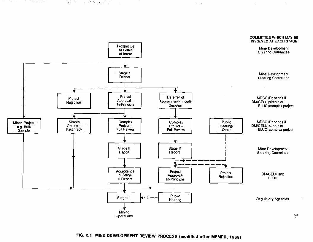
may be applied, as illustrated in Fig. 2.1.
In its current format, the MDRP commences with the filing of a Prospectus or
Letter of Intent with the Mine Development Steering Committee (MDSC). This is a
brief description of the proposed project, and would normally be filed by the
mine proponent following preliminary exploration and prefeasibility studies.
Prospectus or LeUer of Inlent
I +
Stage 1 Report
.------.-1
ProjedProjecl Approval-Rejeclion In-Principle
I ++
Simple Complex Project Project
Fast Track Full Review
~ Slage II Report
! Acceptance
of Siage II Report
I~
• Deferral of
Approval-in-Principle Decision
1 Minor Project-
e.g. Bulk Sample
Complex Project
Full Review
! Stage" Report
t-+.::
• ~
PublicStage III Hearing7-1 I +
Mining Operations
Public Hearing!
Other
I I I
1 , I _____-1
------. Projeci Project
Approval- RejectionIn-Principle
I
COMMITIEE WHICH MAY BE INVOLVED AT EACH STAGE
Mine Development Steering Commillee
Mine Developmenl Steering Commillee
MDSC)Depends if DM/CELUlsimple or
ELUC)complex project
MDSC)Depends jf OM/CELU)simple or
ELUClcomplex project
Mine Development Steering Commillee
DM/CELU and ELUC
Regulatory Agencies
FIG. 2.1 MINE DEVELOPMENT REVIEW PROCESS (modified after MEMPR, 1989)

10.
Except in the case of a very minor project (e.g. bulk sample), the MDSC then
develops terms of reference for a Stage I study, to be carried out by the mine
proponent to address areas of perceived impacts. Following submission and
review of the Stage I report, the MDSC decides if significant unresolved issues
remain, or if more details on specific aspects of the project are required,
before an informed judgement on the project can be made. If required, the MDSC
will then formulate terms of reference for Stage II studies, to be carried out
by the mine proponent to address unresolved issues or details. Approval-in
principle (or a mine development certificate) may be granted, or the project may
be rejected at various stages in the process as indicated in Fig. 2.1.
2.2 RECOMMENDED DESIGN SEQUENCE
Figures 2.2. 2.3 and 2.4 are flow charts which illustrate the recommended steps
in the mine dump design process. These flow charts have been specifically
devised to meet the requirements of the MDRP.
2.2.1 Exploration
Specific investigations and designs for mine rock and overburden disposal
facilities are generally not conducted during the initial exploration
phase of a mining project. However, much of the information which is
collected as a matter of course during exploration, such as topography,
geology, hydrology, climate, etc., may be valuable for subsequent mine
dump assessments. In many cases, if exploration personnel are made aware
of the basic site information which may ultimately be required, it may be
possible to establish an initial data base at relatively little cost
(Stewart and Martin, 1988).
2.2.2 Prefeasibility
Once a project advances beyond the basic exploration stage, it is
necessary to establish the basic mine rock and overburden disposal
requirements. How much and what type of materials must be disposed?
Where will these materials originate? What methods of materials handling

11.
EXPLORATION I PREFEASIBILITY
ESTABLISH POSSIBLE MINE ROCK AND OVERBURDEN CHARACTERISTICS AND QUANTITIES
ASSEMBLE AND REVIEW AVAILABLE SITE INFORMATION
IDENTIFY POSSIBLE DISPOSAL SITES AND POTENTIAL IMPACTS
CONDUCT INITIAL INITIATE BASE LINE SITE RECONNAISSANCE f----------~'4--------______iDATA COLLECTION I
DEVELOP CONCEPTS AND ALTERNATIVES FOR DISPOSAL, POSSIBLE MITIGATIVE MEASURES AND
RECLAMATION
PREPARE PRELIMINARY DUMP CLASSIFICATIONS
IDENTIFY PREFERRED SITES TO BE EVALUATED AND ISSUES TO BE ADDRESSED IN SUBSEQUENT STUDIES
PRELIMINARY DISCLOSURE Prospectus or Application for Mine Development Certificate
FIG. 2.2 RECOMMENDED MINE DUMP INVESTIGATION AND DESIGN SEQUENCEEXPLORATION AND PREFEASIBILITY

12.
FEASIBILITY I PRELIMINARY DESIGN
SITE FOUNDATIONS Field Investigations
Mapping Sampling
Soils Testing
PRELIMINARY STABILITY
~ ASSESSMENTS
~
SITE AND MATERIAL DOCUMENTATION AND CHARACTERIZATION, ENVIRONMENTAL STUDIES DUMP MATERIALS
Surface & Groundwater Sampling I Modelling Material Types & Vegetation, Fish &Wildlife Inventories
I
Quantities Water Quality Testing Sampling
Archaeological, Resources Chemical Analysis & Testing
1
, ESTABLISH BASIC SITE AND MATERIAL
CHARACTERISTICS AND BASELINE ENVIRONMENTAL DATA
PRELIMINARY PRELIMINARY SURFACE AND ...... ASSESSMENT OF
GROUNDWATER ENVIRONMENTAL ASSESSMENTS CONSTRAINTS AND
IMPACTS
DEVELOP PRELIMINARY DUMP PLANS AND IMPACT MITIGATION STRATEGY
ESTABLISH DEVELOP PRELIMINARY DUMP PRELIMINARY
DESIGN RECLAMATION PARAMETERS PLAN
-- '"-....
CONFIRM FEASIBILITY OF PROPOSED DISPOSAL CONCEPT
+ IDENTIFY REQUIREMENTS FOR DETAILED
DESIGN STUDIES
+ PRELIMINARY DESIGN I APPLICATION
FOR MINE DEVELOPMENT CERTIFICATE I
FIG. 2.3 RECOMMENDED MINE DUMP INVESTIGATION AND DESIGN SEQUENCE FEASIBILITY I PRELIMINARY DESIGN

13.
DETAILED GEOTECHNICAL STUDIES
FIELD INVESTIGATIONS e.g. Additional Test Pitting, Trenches.
Drilling, In-Situ Testing. Sampling
, LABORATORY TESTING
Physical Properties of Foundation and Dump Materials
, DETAILED STABILITY ASSESSMENTS
- Parametric Analysis Runout Analysis
, DETAILED GEOTECHNICAL DESIGN
Design Alternatives Design Criteria
COMPREHENSIVE HAZARD/RISK ASSESSMENT
DEVELOP DETAILED DUMP DEVELOPMENT AND RECLAMATION PLANS AND SPECIFICATIONS
PERMITTING (Section 10, Mines Act)
FIG. 2.4 RECOMMENDED MINE DUMP INVESTIGATION AND DESIGN SEQUENCE DETAILED STUDIES / PERMITriNG

14.
and placement will likely be employed? Available site information, such
as the basic geology, topography, vegetation, hydrology, climate,
archaeological information, and any other data available from the
exploration program, other relevant projects or publications (e.g. air
photos, geologic maps, climatic station reports, etc.) is then assembled
and reviewed. Alternative disposal sites and potential environmental and
other impacts are identified for further consideration.
Following this initial review and selection of possible sites, a
preliminary reconnaissance of identified sites would normally be
conducted. Baseline data collection would also be initiated (e.g. stream
flow monitoring, water quality sampling, etc.).
Preliminary evaluations of mine rock and overburden characteristics and
quantities, and site characteristics would be used to develop alternative
conceptual disposal schemes, possible measures to mitigate potential
impacts, and a conceptual reclamation plan. At this stage, preliminary
dump classifications for each of the various alternative sites and dump
development schemes should be prepared, as outlined in Section 5.
Classifications will provide a mechanism for comparing possible
alternatives, and identifying site or dump specific factors which may
ultimately have to be addressed in more detailed studies.
Based on results of prefeasibility studies for mine dumps and other
aspects of the project, a decision would be made by the mine proponent
whether to proceed with a detailed feasibility assessment or not. If a
decision is made to proceed, the proponent would file a Prospectus or
Letter of Intent (or an application for a Mine Development Permit as
described in the pending legislation) outlining the proposed project and
basic approach to development.
2.2.3 Feasibility and Preliminary Design
Feasibility and preliminary design studies would be conducted to advance
project planning and address specific issues raised by the MDSC and

15.
outlined in the Stage I terms of reference. Additional documentation and
characterization of the site and dump materials would be conducted.
Field investigations, such as additional reconnaissance, test pitting,
etc., would be conducted to further assess site conditions and
suitability. Samples of foundation soils would be collected for
classification and laboratory testing. Baseline environmental sampling
and habitat monitoring programs may be initiated or expanded. Estimates
of mine rock and overburden material quantities and composition would be
refined, and samples collected for laboratory testing.
Laboratory studies of foundation and dump materials would be conducted to
establish basic material characteristics, such as shear strength,
durability and chemistry. Surface water and groundwater samples would be
tested to establish baseline water quality. Based on initial laboratory
testing results, sampling and monitoring programs may require adjustment.
A preliminary assessment of the surface and groundwater flow systems, and
a tentative site water balance would be prepared. An initial evaluation
of environmental constraints and potential impacts would be prepared, and
conceptual disposal schemes would be refined and revised accordingly.
Results of all the above studies would be used to develop preliminary dump
plans and an impact mitigation strategy. Preliminary stability
assessments would be conducted to establish appropriate design parameters.
A preliminary reclamation plan would also be developed. Iteration of this
process may be required to establish an economical and environmentally
sound disposal concept. Requirements for subsequent, detailed design
studies would also be identified.
Results of the feasibility and preliminary design studies would be
compiled into a preliminary design (Stage I) report for review by the
MDSC. If no outstanding technical, social or environmental issues are
identified, approval-in-principle would be granted (or a Mine Development
Permit issued). If concerns are identified during review, the project
could be rejected, or approval withheld, pending more detailed studies to

16.
resolve outstanding issues (i.e. Stage II). Detailed design studies may
also be required for permitting (i.e. Stage III).
2.2.4 Detailed Geotechnical Studies
Detailed geotechnical investigation and design studies would be tailored
to the individual project, and the scope of such studies would generally
be determined in consultation with government. As illustrated in Fig.
2.4, detailed studies could consist of additional geotechnical field
investigations to supplement existing information and provide samples for
additional laboratory testing. Additional laboratory testing may be
required to confirm and/or refine geotechnical parameters.
Detailed stability assessments, including parametric or sensitivity and
runout studies, may be required. Detailed assessment of design
alternatives and refinement of design criteria may be necessary, as well
as detailed design of mitigative measures and comprehensive hazard and/or
risk evaluations. Advanced reclamation planning may also be needed. Many
of the factors involved are interrelated; hence, several iterations may be
required to determine the optimum design.
At Stage III (permitting), a comprehensive report summarizing the detailed
studies would be prepared for submission to government. Provided all dump
design issues have been addressed to the satisfaction of the various
regulatory agencies, a permit would be granted under Section 10 of the
Mines Act.

17. /
2.3 BASIC DESIGN CONSIDERATIONS
Basic factors which must be considered in the design of a mine rock and
overburden disposal scheme can be divided into five general categories: Mining
Factors, Physical Constraints, Environmental Impact, Short and Long Term
Stability, and Social/Political Considerations. These factors are interrelated,
and at times conflicts occur. The challenge to the designer is to strike an
acceptable balance between these diverse factors. Conflicts can usually be
resolved, and a balance achieved, through economic analysis, comparative hazard
and/or risk assessments, and engineering judgement.
2.3.1 Mining Factors
Mining factors include those aspects related to materials handling and
mine scheduling. Transportation, for example, commonly accounts for a
large portion of mine rock and overburden disposal costs; hence, it is
usually desirable to locate the dump as close to the source as possible,
with level or downhill hauls to the dump. Scheduling flexibility can also
be an important factor, particularly for large mines where several dumps
may be required or are desirable. Equipment requirements may also vary,
depending on the type and location of the dump.
2.3.2 Physical Constraints
The quantity of dump materials and the basic configuration, location and
capacity of a given dump site may be important physical constraints on
design. Sites may be limited by topographic features such as streams or
excessively steep foundation slopes. Access to some sites may be
impractical or too costly to develop. Depending on the site geometry,
several smaller dumps may be preferable to one major dump. Configuration
and location of the site may also define the optimum construction
technique.

18.
2.3.3 Environmental Impact
Potential environmental impacts influence, and in many cases control, dump
design. Requirements for sedimentation facilities may favour one site
over another. When acid rock drainage is predicted, required mitigative
measures may vary considerably between alternative sites. The potential
impact of waste dump failures may also influence design and must be
evaluated. In addition, reclamation requirements and aesthetics may vary
between sites, and must be considered in the design process.
2.3.4 Short and Long Term Stability
Stability of a mine dump depends on the dump configuration, location,
foundation shape and conditions, foundation and dump material
characteristics and their variation with time, construction methodology
and other factors. Stability considerations may vary depending on the
perceived level of hazard or period of exposure of the dump (i.e. short
term (during construction) vs. long term (abandonment». Hence, the
potential for various types of instability which may impact the safety of
the operation or the environment must be evaluated. Appropriate measures
must then be taken to reduce the risk of instability to an acceptable
level. Overall dump stability, as well as the potential for surface
erosion of reclaimed slopes, must be addressed.
2.3.5 Social/Political Considerations
Resource development projects in British Columbia and elsewhere are being
subjected to increasingly more stringent permitting and regulatory
requirements. Issues such as environmental protection, resource
conservation, native land claims, archaeological significance, aesthetics,
and competing land uses are receiving more attention in the public and
political arenas. Mine proponents must evaluate the public perception and
political acceptability of proposed mine rock and overburden disposal
alternatives early in the design process.

19.
3. SITE CHARACTERIZATION AND FIELD STUDIES
3.1 GENERAL
Rational mine dump site selection and design requires a thorough knowledge of
the physical and biological characteristics of the site and potential dump
materials. Those characteristics which are considered most important are
described in the following and summarized in Table 3.1. For discussion
purposes, key site characteristics have been grouped into six broad categories
or study areas. The primary impacts that each of these study areas has on the
site selection and design process are also described.
The first step in site characterization is to assemble available information
from government publications, maps, basic environmental data and public and
private company reports. Much of the required information may already have been
collected in connection with other aspects of the project or related or adjacent
studies. Some of the available sources of information which may be useful are
described in the following and summarized in Table 3.1.
Field investigations are then planned and executed to define and confirm the key
site characteristics. The scope of field investigations may vary from a
preliminary site reconnaissance, to detailed drilling, geophysical surveys,
sampling and instrumentation programs. The design of field investigation
programs will depend on a wide variety of factors, including site conditions,
the size of the proposed dump and the amount of information already available.
Typical field investigation techniques are described in the following and
summarized in Table 3.1. Some useful references which describe some of the
typical field investigation techniques in greater detail are also given in Table
3.1.
Information requirements commonly change as a more thorough understanding of
site characteristics evolves during the course of the study. Hence, it is
important that field investigation programs be comprehensive yet flexible. A

TABLE 3.1 SITE CHARACTERIZATION AND FIELD METHODS
SITE SELECTION AND AVAILABLE FIELD METHODS STUDY AREAS IMPORTANT CHARACTERiSTICS DESIGN IMPLICATIONS INFORMATION SOURCES PRELIMINARY STUDIES DETAILED STUDIES REFERENCES
-Sile location, size, shape, -Overall site sUitability -Martin (1991): 1,2,5-14, topography -Haul distance. grades -Air photo Interpretation, terrain 17,21,22,24-28,28,32
Physiography -Geologic hazards (eg. lands.lides, -Stabilization or mitigative -Topographic maps analysis (1) -Photogrammetric mapping (21) -Piteau Associates(1990): and debris flows. etc.) works -Air photos -Ground reconnaissance. terrain -Ground surveys (22) 12-15,18,29,30
Geomorphology -Landlorms (eg. terraces, gulleys. -Topographic constraints mapping (2) -OSM (1989): 8-12,28-29 etc.) -Dump type. construction -Environment Canada
-Glacial hislory method (1988): 23 -Diversions and rock drains -CCREM (1987): 18,18,
-Precipitation (ralnlall and snowfall) -Snow accumulation/removal -Topographic maps -Ground reconn, stream 19,35 Hydrology -Temperature -Flooding potentIal -Air photos mapping (3) -Fisheries & Oceans
and -Prevailing winds -Freeze-thaw degradallon -Climatological station -Stream now measurements (eg. -Ground surveys (22) (1987): 18,19,34,35
Climate -Runofflinliltration characteristics potentIal records weirs. staff gauges. current -Establish climatological station (23) -CGS (1985): 1.8-10,21, -Locations 01 streams -Avalanche hazards -Water license records metering) (4) 28-28
-Size 01 catchment basins -Impact on surface water -Environment Canada resources (1983): 18,18
-Air photos, topographic -USBM (1982): 1,2,5-9. -Foundation condilions. maps 11.28,27
Bedrock -Geologic structure stability -Geologic maps or open -Air photo interpretation (1) -Welsh (1981): 1,2,22,28
Geology -Rock competency, durability -Impact on potential minerai file reports -Ground reconn, outcrop -Geotechnical exploration drilling (24) -Freeze & Cherry (1979):
and -Potential minerai resources resources -Regional geology studies. mapping (5) -Additional trenching , test pilling (8) 15-17,29,31-33
Tectonics -Seismicity -Seismic stability theses -Trenching, test pitting (8) -Geotechnical core logging (25) -Naismith & Gerath -Characteristics 01 mine -exploration drill logs. -Exploratlon drilling (7) (1979): 1
rock materials. stability reports -ELUC (1978): 1 -Seismic zoning maps -CANMET (1977): 8,8,12,
-Foundation conditions. -Air photo Interpretation (1) -Additional trenching , test pitting (8) 28,27 -Soli types. distribution, stability -Air photos, topographic -Ground reconn, solis mapping (8) -Geotechnical boreholes (eg. mud/air -Goodman (1978): 1,7,21,
Surllclal stratigraphy -Foundation preparation. maps -Trenches, test pits. grab rotary, Becker, auger, etc.) (28) 24
Geology/Solis -Depth to bedrock or competent remediation -Surliclal geology or solis sampling (8) -Downholelinsitu testing -Keser (1978): 1
soli -Characterlsllcs 01 maps, reports -Soli classification (9) (e.g. SPT. CPT etc.) (27) -Dept. olthe Navy(1975):
-Insitu soli characteristics overburden materials. -Exploration drill logs -Soft soli probing (10) -Split spoon, thin wall, block 6,8-11,16,26-28,31-33 stability -Insitu testing (eg. vane shear, sampling (28) -Linsley et al (1975): 4
pocket penetrometer. etc.) (11) -Geophysics (29) -MESA (1975): 2.3,5-7.11,
-Air photos. topographic -Air photo Interpretation (1) -Geotechnical boreholes with open 16,18,22,28-28,30-32
-Locallon 01 springs. seeps, -Foundallon conditions. maps -Ground raconn, hydrogeologic standpipes and/or sealed -Peck et al (1974): 8-11.
perched water tables, phreallc stability -Geologic maps. reports mapping (12) piezometers (30) 27,28
Hydrogeology surlace -Underdralnage -Exploratlon drilling records -Inflows to trenches. test pits (13) -Geophysics (29) -Compton (1962): 5.22
-Piezometric pressures requirements water level measurements, -Shallow standpipes in test pits (14) -Pump testing (31)
-Groundwater flow system -Impact on groundwater piezometers -Groundwater sampling (15) -Insitu permeability testing (32)
-Existing groundwater useage resources -Well logs -Field testing 01 phys. properties (16) -Inliltrometer testing (33) -Water licenses -Perc tests (17)
-Surlace and groundwater quality -Establish baseline data lor -Surface and groundwater
-Air quality impact assessments -Air photos. topographic sampling (18)
Environment -Fish and wlldllle habitat -Mitigative measures maps -Field testing 01 physical -Wildlile habitat studies (34)
and -Plant, forestry resources -Establish luture land use -Forestry, land use maps properties (16) -Biophysical monitoring (35)
Culture -Present land use objectives -Land registries -Flah, wlldlile and plant -Air quality monitoring (38)
-Aesthetics -Politlcel, legal -Local population, Indian Inventories (19)
-Land ownership. native land clalms considerations bands -Archeological reconnaissance (20)
-Archeological resources . .NOTE. Numbers In parentheses reler to the selected relerences listed on the lar nght which contam detailed descnpllons and/or speclllcations lor the various field tests.
N o

21.
phased investigation usually provides the most cost effective and efficient
method of obtaining the required information. In cases where the project
schedule does not enable a phased approach, delays may occur during later stages
of project development, while critical missing information is collected.
Increased investigation, design and construction costs may also be incurred if
field investigations are compressed or truncated.
3.2 PHYSIOGRAPHY AND GEOMORPHOLOGY
The physiography of the site refers to its location, shape, size and topography.
Location of the site and proximity to the source of the waste directly affects
haulage costs. Other mining activities such as blasting, access development,
layout of mine facilities, etc. may affect site selection, development and dump
stability considerations. Size and shape affect the suitability of the site in
terms of available capacity, type of dump and construction concepts.
Topographic constraints, such as steep slopes, major drainages or divides, may
place additional physical limitations on the site, and may also affect selection
of the type of dump and construction methodology.
The geomorphology of the site refers to the geological origin of various
landforms and active geologic processes. Understanding the geomorphology
provides insight into the nature of site soils. For example, colluvial deposits
might be expected in the lower sections of moderately steep bedrock slopes, or
terrace deposits might be expected on the slopes of large valleys. The
occurrence of landslides, or other geologic hazards such as debris flows, debris
torrents or avalanches, may require stabilization or construction of mitigative
works. Some landforms, such as river or kame terraces and gullies, may have
positive influences on dump stability, and can often be used to advantage during
dump construction, although special seepage control measures may be required.
The main sources of available information on site physiography and geomorphology
consist of topographic maps and air photos. Topographic maps at a scale of
1;50,000 are available for the entire province through the Surveys and Mapping
Branch of EMRC. Air photo coverage at a variety of scales is available through
the B.C. Ministry of Crown Lands - Surveys and Resource Mapping Branch (MAPS

22.
B.C.). In addition, larger scale and specialized maps (e.g. soils maps, terrain
maps, etc.) are also available for some areas from MAPS-B.C., MOE, and the B.C.
Ministry of Forests.
Preliminary field investigations of site physiography and geomorphology would
normally consist of a terrain analysis based on available maps and air photos.
This would be followed by ground reconnaissance and mapping of significant
terrain features. Depending on the detail of available mapping, and complexity
of the site, photogrammetric mapping and/or ground surveys might be required at
later stages of the study to prepare more detailed maps.
3.3 HYDROLOGY AND CLIMATE
The hydrology of a particular dump site may limit its use. Dump sites with
defined drainage courses may require construction of diversions or flow-through
rock drains. Climate patterns, frequency and severity of storm events, snow
packs, temperatures and the size of catchment basins all influence runoff and
stream flows, and may affect dump stability. Areas with high precipitation may
require special construction methods to control runoff and minimize infiltration
into the dump. Heavy snow accumulations may lead to seasonally adverse
conditions within the dump and foundations, and limit operations. On the other
hand, prevailing winds may prevent significant snow accumulations. Mining and
dump construction may also significantly change the amount of infiltration and
distribution of runoff, with a consequent impact on surface water resources.
Topographic maps and air photos provide useful information on drainage patterns
and catchment basins. Hydrologic records may be obtained from MOE or Water
Survey of Canada. Climatological station records are-available for many sites
from Environment Canada. Water license records are also maintained by MOE. In
addition, seasonal precipitation maps are available for some areas through MAPS
B.C.
Preliminary field investigations would normally include basic ground
reconnaissance and stream mapping. A program of periodic measurement of any
perennial streams which may be affected by the proposed dumps, would normally be

23.
initiated early in the investigation. Flow monitoring could be conducted
utilizing staff gauges, weirs or current metering on measured cross sections.
It is generally good practise to establish a climatological station at the mine
site. In addition, detailed ground surveys might be required for design of
diversions and/or flow-through rock drains and contaminated seepage collection
systems.
3.4 BEDROCK GEOLOGY AND TECTONICS
The geological setting of the mine and dump should be considered during site
selection and design. Adversely oriented geologic structures, such as faults,
bedding planes or joints, may affect the stability of the foundation, and could
influence surface drainage patterns and groundwater flow systems. Competency
and durability of the bedrock may limit allowable bearing loads, or influence
dump configuration and construction concepts. A knowledge of the geology of the
dump site will also be required to assess the possibility of economic mineral
.deposits occurring beneath the site.
A knowledge of the geological characteristics of the mine rock materials which
will form the dump is also required. Key parameters such as lithology,
alteration, weathering, geologic structure and rock fabric influence the
strength, gradation, durability and other important characteristics of the dump
materials.
An understanding of regional tectonics is important in evaluating seismic risk.
Proximity to major tectonic faults and earthquake epicentres may influence the
types of stability analyses, factors of safety, and design approaches deemed
appropriate for a given site.
Sources of available information on geology may include published and
unpublished geologic maps, open file reports, regional and local geology
studies, theses and journal articles. This type of information is commonly
available through the Geological Survey of Canada (GSC) , universities and public
libraries. Available exploration reports and drill logs should also be
reviewed. Air photos and topographic maps may provide some insight into the

24.
bedrock geology and structure. Seismic zoning maps and hazard assessments are
available through the GSC.
Preliminary field studies would normally include air photo interpretation,
ground reconnaissance and outcrop mapping, supplemented by trenching or test
pitting, if required. Drilling records and cores would be examined and
geotechnical core logging may be conducted to supplement geologic logging and
assist in characterizing the rock mass. If bedrock exposures are limited, and
exploration drilling coverage is sparse, additional drilling may be required.
3.5 SURFICIAL GEOLOGY AND SOILS
An understanding of the surficial geology of the site is essential to be able to
evaluate foundation conditions and overburden material characteristics for
stability analysis and design, and to determine foundation preparation
requirements. It is necessary to determine the origin, nature, distribution and
stratigraphy of site soils, and the depth to bedrock or competent soil strata.
Particular emphasis must be placed on determining the characteristics and extent
of soft, loose or incompetent soils which may affect foundation stability or
which may be incorporated into the dump.
Sources of information on surficial geology and site soils include published
surficial geology maps and reports, soil survey studies and soils maps, theses
and journal articles. These are commonly available through the GSC, MAPS-B.C.,
and university and public libraries. In addition, geological maps and reports
often make reference to, and describe, surficial soils. Air photos and
topographic maps are also useful sources of information. Exploration reports
and drill logs may include information on the general character and depth of
surficial soils. Water well logs may also be a source of information.
Surficial geology investigations commonly begin with a preliminary
interpretation of black and white and/or colour air photos, followed by ground
reconnaissance and mapping of soil exposures in road cuts, stream channels, etc.
Trenching and test pitting should be employed to further define and classify
soil types and distribution, and to obtain representative samples for laboratory

25.
index testing. Soft soil deposits, such as peat or organic rich soils, should
be probed to determine depth and extent. In situ testing, such as hand-held
vane shear or pocket penetrometer testing should be conducted in test pits and
trenches, where practical, to provide an initial indication of soil strength
properties.
If significant deposits of potential problem soils are identified during the
preliminary investigations, more detailed field studies should be carried out.
Such studies would likely include geotechnical borings using mud or air rotary,
Becker, hollow or solid stem augers, vibracore or other types of drilling rigs.
The choice of the drilling rig would depend on cost, availability, types of soil
deposits to be drilled and sampling objectives. Downhole in situ testing, such
as standard penetration, cone penetrometer or pressuremeter would be used to
assess the distribution, density, strength and stratigraphy of problem soils.
Representative samples would be obtained, consisting of split-spoon or pitcher
samples (i.e. disturbed) for basic stratigraphy and classification, or thin
walled (e.g. Shelby, piston) samples or block samples (i.e. undisturbed samples)
for more sophisticated testing. In cases where a detailed knowledge of the in
situ density, stratigraphy and/or depth to bedrock is required, geophysical
methods, such as seismic refraction, resistivity and shallow radar, would be
employed to supplement information from test pits, trenches or boreholes.
3.6 HYDROGEOLOGY
Foundation conditions, stability and requirements for underdrainage or liners
are directly influenced by the hydrogeology of the site. In addition, mine dump
construction can have a significant impact on the groundwater and surface water
resources. To be able to evaluate the potential impacts, it is first necessary
to develop an understanding of the groundwater flow systems and the basic
hydrogeologic characteristics of the site. Basic information that is required
includes the distribution of discharge and recharge areas, climatic conditions,
geometry and hydrogeologic characteristics of the various soil and bedrock
units, position of the water table and the occurrence of perched water tables,
distribution of piezometric pressures and information on current groundwater
usage.

26.
Sources of information on site hydrogeology are generally scarce, and site
specific studies will be required to develop the necessary data. Regional
hydrogeologic maps or studies are generally not available. However, exploration
drilling records which indicate drilling fluid consumption and returns, standing
water levels in boreholes, and general groundwater conditions or drilling
difficulties are useful sources of information. (Well logs, pumping tests on
domestic or irrigation wells and water license records, all of which are
available through MOE, are also useful.) In addition, topographic maps, air
photos and agricultural or forestry maps and reports can provide useful insight
into groundwater flow systems and usage. Some geologic and surficial geology
maps and reports also make reference to groundwater conditions, the occurrence
of significant aquifers, etc.
The first step in a hydrogeological investigation consists of a preliminary
identification of possible groundwater discharge areas using air photos and
topographic maps. This desk study is then followed by ground reconnaissance and
basic hydrogeologic mapping (i.e. location of springs, seeps and other evidence
of groundwater discharge). Groundwater levels in local wells, and inflows into
trenches and test pits would be documented, and shallow open standpipe
piezometers may be installed. Sampling of wells or drillholes and other sources
of groundwater, and field testing of physical properties (e.g. temperature, pH
and conductance) would also be conducted. Simple percolation tests would be
carried out to gain an initial appreciation for the infiltration characteristics
of the surficial soils.
If significant aquifers are identified beneath the site, or potentially adverse
groundwater conditions are encountered, more detailed hydrogeological
investigations would be required. Open standpipes and/or sealed piezometers
would be installed in existing boreholes or holes drilled specifically for
hydrogeological investigations. In situ permeability testing of sealed
piezometers and pump testing of major aquifers would be conducted. In unusual
cases, where a detailed knowledge of the flow systems is required, flow tracing
with fluorescent dyes or radioisotopes, or geophysical methods (e.g.
resistivity, refraction seismic, etc.) would be used to supplement borehole and

27.
piezometer information. More sophisticated infiltration testing (e.g. double
ring infiltrometer) would also be carried out if evaluation and design of a
contaminated seepage collection system was required.
3.7 ENVIRONMENT AND CULTURE
One of the prime objectives of a mine dump design is to minimize the impact of
the development on the environment. Protection of cultural and other resources
is also a priority. To be able to rationally assess potential impacts and
develop mitigative measures, it is necessary to document environmental
conditions and resources at the outset of the project. The important
environmental characteristics which must be evaluated include surface water
quality, groundwater quality, air quality, fish and wildlife habitat and
productivity, and vegetation. Present land uses must be identified, and
existing and potential forestry and agricultural resources evaluated.
Archaeological and recreational resources must be identified, and the aesthetics
of the site must be considered. Also, questions of land ownership and
acquisition, and the potential for native land claims must be addressed.
Sources of information on environmental, cultural and other resources include
forestry, agricultural and land use maps, which are available for many areas of
the province through MAPS-B.C. Information on local fish and wildlife may be
available through MOE, Fisheries and Oceans Canada, Parks Canada, Environment
Canada and other government agencies. Air photos and topographic maps are also
useful. Land registry offices and local government agents may provide relevant
data. Consultations with the local population at an early stage of the project
are strongly advised.
Baseline environmental investigations should include surface and groundwater
quality sampling and field testing of basic physical properties (e.g. pH,
temperature and conductance). Site reconnaissance, documentation of habitat,
and inventorying of fish, wildlife and vegetation species must also be
conducted. Archaeological reconnaissance should also be conducted.

28.
The above is intended only as a general discussion of the nature and scope of
environmental and cultural studies which might be required. It is essential
that appropriate government agencies (e.g. B.C. Ministry of Environment,
Environment Canada, Fisheries and Oceans Canada, etc.) be contacted at an early
stage of project evaluation to determine the specific requirements for
documentation and baseline monitoring, as well as appropriate field procedures.
It is important to note that comprehensive environmental, cultural and socio
economic studies relating to the overall site and surrounding lands are required
for overall project approval. Detailed, dump specific investigations would be
determined in the context of the overall environmental/cultural impact
assessment.

29.
4. MATERIAL PROPERTIES AND TESTING
4.1 GENERAL
The engineering properties of foundation and dump materials are required for
design. It is equally important to establish baseline surface and groundwater
quality data against which to predict the overall impact of the dump on the
environment, and to provide a benchmark for ongoing monitoring.
Selecting and obtaining representative samples for materials testing,
interpreting results and applying them to design requires a thorough
understanding of the various components of the physical environment outlined in
Section 3 above. The type and amount of testing required will vary, depending
on: the complexity of site conditions; the location, type, size and
configuration of dump; the environmental sensitivity of the site; and other
factors. For large dumps, or dumps located on a complex and environmentally
sensitive site, substantial detailed testing may be required. In cases where a
probabilistic approach to design is adopted, a large testing program may be
required to supply sufficient data for statistical analysis.
Many of the parameters required for analysis and design may be derived from
empirical criteria based on qualitative classifications and descriptions.
However, where testing programs are limited in scope, or critical parameters
cannot be reliably determined using available and practical testing techniques,
conservative assumptions and design approaches must be adopted.
4.2 FOUNDATION SOILS
Important properties of foundation soils, their application in the design
process, and methods for measuring them in the field and laboratory are
described in the following and summarized in Table 4.1. More detailed
descriptions of the various soil properties are given in most introductory soil
mechanics text books, such as Craig (1983), Peck et al (1974) and Terzaghi and
Peck (1967). OSM (1989), USBM (1982) and MESA (1975) all provide good

TABLE 4.1 MATERIAL PROPERTIES AND TESTING FORFOUNDATION SOILS
MATERIAL PROPERTIES APPLICATION IN SITU I FIELD
TESTING LABORATORY
TESTING
REFERENCES
DESCRIPTION
-Colour
-Odour
-Texture
-Fabric, structure
-Sqils mapping, classification, interpretation
. -Identification of problem soils
-Weathering characteristics
-Important structures, fabric
-Various empirical correlations
-Grouping samples for testing
-Field description (1) -Microscopic examination (20) -Martin (1991): 6.11,18
-BCAMD Task Force (1990): 32-34
-oSM (1989): 4,6,10,12,16,18,
19,21-30,32-35
-CGS(1985): 1-6,10,12,16.17
-Craig (1985): 1-6,8,12,14,16,
17,21-30,35
-USBM (1982): 6,10,12,26,27,29.
30,35
-Zavodni et al (1981): 7
-Freeze & Cherry (1979): 6-8.
26.33.34
-Hurlbut & Klein (1977): 20,31 -Kerr (1977): 20
INDEX PROPERTIES
-Gradation
-Plasticity
-MoIsture content
-Unit weight
-Specific gravity
-Classification
-Empirical correlations with permeability,
strength. consolidation
-Volumelweight relationships
-Visual estimation of gradation (2)
-Estimation of plasticity via
dilatancy. toughness. dry strength (3)
-In situ density/moisture testing (4)
-Preliminary classification (5)
-Sieve (21)
-Hydrometer (22)
-Atterberg Limits (23)
-Various direct and indirect
methods of measuring volume/
weight parameters (24) -Lab classification (25)
HYDRAULIC -Estimation of seepage, drainage quantities -Piezometer and borehole testing (6) -Permeameter (26) CONDUCTIVITY -Prediction of piezometric conditions -Infiltration testing (7) -MESA (1975): 2,3,6.21-24,
-Assessment of elfectiveness of solis -Pumping tests (8) 26-29,35 as natural liner -Peck et al (1974): 1-5,10,12.
16.18.21-30.35 -Dept. olthe Navy (1971): 1-3,5,
9.10.12.18.21-27
-Terzaghi & Peck (1967): 1.2.5,8,
CONSOLIDATION -Pore pressure dissipation
-Settlement -Survey monuments. settlement plates and piezometers In conjunction
with test fill (9)
-Consolidation (27)
STRENGTH -Foundation stability -Empirical correlations with -Unconfined compression (28) -Bearing capacity penetration tests (10) -Direct shear (29) 9,10.12.14.16.18,21-30,35 -Strain to failure -Field hardness (11)
-Vane shear (12) -Pocket penetrometer (13)
-Back analysis of natural failures (14)
-Triaxial (30) -Lambe (1951): 21-30,35
MINERALOGY I -Presence of swelling or low friction clay -Acid test for carbonates (15) -X-ray dllfraction. scanning
SOIL CHEMISTRY minerals
-Neutralization. adsorption potential
-Documentation of existing contaminant
levels
electron microscope (31)
-Acid-base accounting (32)
-Adsorption (33)
-Other physical/chemical tests to
to detect specific contaminants (34)
IN SITU DENSITY -Empirical correlation with strength,
settlement, liquefaction potential
-Penetration testing (16)
-Pressuremeter (17)
-Geophysics (seismic. density logging) (18)
-Consolidation (27)
COMPACTION -Design of liners -Design of mitigative or remedial measures
-Volumeter, sand cone. nuclear
densometer on test fills (19)
-Consolidation (27)
-Standard, Modified Proctor (35) w o
NOTE: Numbers In parentheses refer to the selected references listed on the far right which contain detailed descriptions and/or specifications for the various field and laboratory
tests.

31.
discussions on basic soil parameters, and field and laboratory testing methods.
CGS (1985) and Dept. of the Navy (1971) describe in situ testing and sampling
techniques. A comprehensive summary of the most common laboratory tests, ASTM
testing specifications and guidelines for interpreting and correlating test
results is given in Dept. of the Navy (1971). Detailed sample specifications
and testing procedures are described by Lambe (1951), ASTM and BSI (1975).
4.2.1 Description
All significant soils units and weathering horizons occurring within the
site should be described. Descriptions should generally include: colour,
grain size, fabric or structure, odour, texture, etc., and are useful in
identifying an~ classifying basic soil types and weathering
characteristics.
Descriptions also provide a useful means for separating soil samples into
representative groups for subsequent testing. As indicated above, many
soil parameters required for analyses can be derived from empirical
correlations based on descriptions of soil types and preliminary soil
classification.
Preliminary soil descriptions are commonly prepared in the field, in
conjunction with reconnaissance, test pitting and drilling. These
descriptions are based on how the soil looks to the unaided eye or under a
hand lens, and how it feels and smells. Field conditions are commonly not
ideal, and some sampling techniques, such as thin walled piston samples,
do not lend themselves to detailed descriptions in the field. Hence, a
follow-up laboratory description of selected samples, possibly including
microscopic examination, is recommended.
4.2.2 Index Properties and Classification
Index testing should be conducted on each of the major soil groups and
weathering horizons identified during field investigations. Index
properties such as gradation and plasticity are important for soil

32.
classification. Index properties also provide an indication of some of
the key engineering properties, such as shear strength, permeability and
consolidation. Parameters such as natural moisture content, unit weight
and specific gravity, provide information on the volume-weight
relationships of the soil, which are used in a wide variety of
calculations including: consolidation rates, pre-consolidation pressures,
porosity, stability calculations, etc. Natural moisture content also
provides an indication of the in situ state of the soil in relation to its
plastic and liquid limits.
Preliminary visual estimates of gradation are prepared in the field. The
experienced geotechnical engineer can estimate the percentage of cobbles
and boulders, gravel, sand, silt and clay. The consistency or plasticity
of fine soils is qualitatively estimated using simple field tests such as
dilatancy, dry strength or toughness.
Field descriptions and estimates of index properties are used to prepare a
preliminary soil classification. Although numerous classification schemes
are available, the Unified Soil Classification System (USCS) (Wagner,
1957) is the most widely used and accepted, and is applicable to most of
the soil types likely to be encountered. One exception is very coarse
grained soils consisting predominantly of cobbles and large boulders. In
such cases, percentage estimates of boulder sizes, shapes and lithologies
should accompany the USCS classification of the finer (i.e. gravel size
and smaller) fraction of the soil.
Laboratory testing of index properties is conducted to confirm field
estimates and refine preliminary classifications. Laboratory gradation
analysis consists of sieve testing of coarse grained soils and hydrometer
testing of fine grained soils. Combined sieve/hydrometer testing may be
required for mixed grained soils. Atterberg.Limits (e.g. plastic limit,
liquid limit, etc.) and natural moisture content are used to assess the
consistency of the soil. Specific laboratory tests are also available for
measuring such parameters as dry unit weight, specific gravity, porosity,
etc.

33.
4.2.3 Hydraulic Conductivity
A knowledge of the hydraulic conductivities of the various soil units is
necessary for seepage analysis, prediction of piezometric conditions
within the foundation, assessment of the effectiveness of natural and
constructed liners and design of underdrainage measures. For simple, low
hazard dumps, or for preliminary studies, order of magnitude estimates of
hydraulic conductivity based on empirical correlations with index
properties (e.g. grain size) and soil descriptions, and percolation tests
in hand-dug holes, may be sufficient. For more complex dumps, dumps in
sensitive environments or on difficult foundations, or where specific
measures for liners or seepage collection systems are required, more
accurate measurements of hydraulic conductivity. based on specific field
and laboratory testing, will be required.
In situ field measurement is usually the most reliable method for
obtaining hydraulic conductivity data. In the field. materials can be
tested in their natural state with minimal disturbance. Also. such
factors as structure and fabric. which may have a significant influence on
hydraulic conductivity, are difficult or impractical to simulate in the
laboratory.
Double-ring infiltrometer testing would be conducted for detailed
evaluation of the infiltration characteristics of the natural soils, and
to confirm the assumed hydraulic conductivity of constructed liners.
Falling head tests in piezometers or open boreholes would be conducted to
assess in situ hydraulic conductivity of specific soil strata. Where
significant aquifers occur, packer testing and/.or pump testing would be
required to determine aquifer parameters such as storativity and
transmissivity.
Laboratory permeability testing would consist of constant or falling head
permeameter tests on relatively undisturbed samples, such as thin walled
piston or Shelby tube samples. Compaction permeameter testing of
reconstituted samples would conducted to determine hydraulic conductivity
34.
parameters for underdrainage or liner design. Hydraulic conductivity
measurements would also be obtained in conjunction with consolidation
testing of fine grained soils as described below.
4.2.4 Consolidation
Where dumps founded on fine grained soils, an assessment of the
consolidation characteristics of the underlying soils will be required.
This information is necessary to be able to predict foundation settlements
and the potential for generation and dissipation of excess pore pressures
due to dump loading. Excess pore pressures in dump foundations can
significantly reduce overall dump stability during construction;
consequently, s~fe dump advancement rates may be limited by the rate at
which excess pore pressures can be dissipated.
Consolidation settlement of foundation soils may also reduce infiltration
and improve the shear strength characteristics of foundation materials.
Conversely, consolidation of foundation soils will induce strain in the
dump material, with a consequent change in shear strength and behaviour.
If substantial settlements do occur, drainage blankets, finger drains,
lined ditches, etc., may be disrupted, and this must be taken into
consideration in the design of such measures.
Laboratory testing consists of one-dimensional consolidation testing on
undisturbed samples. Alternatively, consolidation and hydraulic
conductivity parameters may be obtained from the consolidation stages of
certain types of triaxial and direct shear tests. Where excess pore
pressure dissipation rates or settlement are critical to design,
confirmation of parameters based on laboratory testing using field
monitoring of test fills is recommended. Monitoring would likely consist
of settlement plates and survey monuments to record displacements, and
piezometers to monitor pore pressures.

35.
4.2.5 Strength
The shear and compressive strength characteristics of the foundation
materials are required for assessment of foundation stability and bearing
capacity. For preliminary assessments, or where dumps are founded on
competent soil strata (e.g. over consolidated, hard glacial till; dense
sand and gravel; dense colluvium, etc.), conservative estimates of shear
strength may be used, based on correlations with soil classifications and
index properties (e.g. Terzaghi and Peck, 1967; Dept. of the Navy, 1971)
and simple in situ strength index testing (e.g. pocket penetrometer, hand
held vane shear, etc.). In addition, natural slope or previous foundation
failures should be back analyzed for effective strength parameters.
Where foundation conditions are complex, or foundation soils are fine
grained, soft or susceptible to consolidation, pore pressure generation or
other adverse effects, more detailed field and laboratory testing would be
required. The number and type of tests to be conducted, and conditions of
testing, depend on the complexity of site conditions, the nature of the
soil to be tested and the loading conditions to which it will be
subjected.
Where fine grained soils are present in the dump foundation, they will
commonly be the weakest strata and merit the closest attention.
Undisturbed samples (e.g. Shelby tube, piston samples, block samples)
obtained from geotechnical boreholes or test pits would be subjected to
unconfined compression, triaxial compression or direct shear. Test
conditions (e.g. pore pressures, strain rate, loading rate,
preconsolidation pressures, confining stress, etc.) would be controlled to
simulate conditions both during dump construction (normally the worst
case), and over the long term. Sufficient tests would be conducted to
reliably establish the stress/strength characteristics of each unique soil
strata.
Undisturbed samples of mixed grained or coarse grained soils are usually
difficult or impractical to obtain. Softened glacial tills may present a

36.
particularly difficult sampling and testing problem, if they contain
appreciable amounts of gravel, cobbles or boulders. If it is not possible
to obtain reasonable undisturbed samples of such materials, pocket
penetrometer or vane shear testing may provide the most reliable strength
information. Laboratory strength testing of mixed or coarse grained soils
is generally limited to triaxial or direct shear testing of reconstituted
samples, which may not be very representative of in situ soil conditions.
Test results are commonly interpreted as lower bound or conservative
assessments of strength, and testing would normally only be conducted
where preliminary assessments based on conservative strength assumptions
indicate that the shear strengths of these materials is critical to
design. One exception would be if unfavourably oriented discontinuities
(e.g. bedding planes, slip planes, etc.) occurred within mixed grained
soils and could be sampled intact. In such cases, direct shear testing
along the discontinuity would be conducted.
In situ testing of complex, sensitive soil conditions would be carried out
in conjunction with geotechnical drilling, and would normally consist of
Standard Penetration or cone penetrometer testing. Empirical correlations
are available which relate penetration resistance with shear strength and
other parameters (e.g. CGS, 1985; Dept. of Navy, 1971; Peck et aI, 1974).
Penetration testing would also be used to correlate results of laboratory
shear strength testing with in situ conditions.
4.2.6 Mineralogy and Soil Chemistry
The presence of swelling or low strength clay minerals can have a
significant impact on the shear strength characteristics and behaviour of
the soil. In addition, soil chemistry and clay mineralogy influence the
ability of the foundation materials to neutralize leachate and adsorb
contaminants released from the dump.
Although some basic soil chemistry parameters can be measured in the
field, the bulk of testing is done in the laboratory. Mineralogical and
contaminant testing, consisting of x-ray diffraction studies or other

37.
chemical or physical tests, would be conducted if problem clays or
contaminants are anticipated, or in cases of very sensitive environments.
Acid-base accounting of foundation soils would be conducted if a potential
exists for acid generation in the waste materials.
4.2.7 In Situ Density
The in situ density of soils directly impacts shear strength, the
potential for settlement of the foundation, and resistance to liquefaction
during construction or in an earthquake. Empirical correlations between
density, liquefaction potential and penetration indices (Standard
Penetration, cone penetration, pressuremeter) are available (e.g. Seed and
de Alba, 1986). As indicated above, penetration testing would normally be
carried out in conjunction with geotechnical drilling. Where foundations
consist of sandy or silty soils, such as on flood plains, in situ density
testing is strongly recommended to assess the potential for liquefaction.
In situ density of fine grained soils would also be determined in the
laboratory in conjunction with other testing (e.g. consolidation, shear
strength, etc.).
4.2.8 Compaction
Assessment of the compaction characteristic of the foundation soils would
be required if foundation remedial or mitigative measures are
contemplated, such as proof rolling or berm or liner construction. Field
measurements are generally restricted to density measurements on test
fills or proof rolled soils using nuclear densometers, sand cones or
volumeters (Dept. of Navy, 1971). Laboratory compaction testing usually
consists of Standard or Modified Proctor density testing (Lambe, 1951).
4.3 FOUNDATION BEDROCK
In addition to the basic geologic characteristics of the foundation bedrock,
which would normally be evaluated during the field investigation phase (see
Section 3.4), other properties of the bedrock which may be important in design

38.
are described in the following and are summarized in Table 4.2. Field and
laboratory methods for characterizing important bedrock parameters are also
given in Table 4.2. In the case of very weak, soil-like rocks, similar
investigation and testing requirements as described above for foundation soils
would be required. More detailed descriptions of the various bedrock properties
are given in most introductory rock mechanics text books, such as Goodman (1980)
Martin (1991), CGS (1985) and Hoek and Bray (1977) describe field data
collection and sampling. Laboratory testing techniques and specifications are
described by Martin (1991), Jaeger and Cook (1970) and ISRM.
4.3.1 Description
Descriptions of each of the major rock units identified during the field
investigations should be prepared, and the rock classified according to
lithology and origin. Basic descriptions and classifications are useful
in assessing the general character of the bedrock. Preliminary,
qualitative estimates of important parameters, such as compressive
strength and durability, may be based on typical values for a particular
rock type (e.g. Goodman, 1980; Hoek and Bray, 1977). In many cases,
further testing of the bedrock may not be required.
Normally, an experienced geologist or geotechnical engineer would be able
to describe the rock types in sufficient detail in the field using the
unaided eye or a hand lens. However, in some cases (e.g. fine grained or
clay-rich rocks), a more thorough investigation of the mineralogy or
petrography of the rock, such as described below, may be required to
adequately describe the rock.
4.3.2 Strength
The intact rock strength and the shear strength of discontinuities may
have an influence on the stability or bearing capacity of the foundation.
Preliminary estimates of compressive strength may be based on empirical

TABLE 4.2 MATERIAL PROPERTIES AND TESTING FOR FOUNDATION BEDROCK
MATERIAL PROPERTIES APPLICATION IN SITU I FIELD
TESTING
LABORATORY
TESTING
REFERENCES
-Martin (1991): 3,4,8,9,13-18,
19-21
-OSM (1989): 1,2,8,14-18,19,20
-eGS(1985): 1,2,3
-Barton & Kjaernsli (1981): 5
-Zavodni et al (1981); 10
-Freeze & Cherry (1979): 9-11,18
-Hurlbut & Klein (1977): 12,17
-Kerr (1977): 12
-Peck et al (1974): 1,2,8,9,11,
14-18,19
DESCRIPTION
-lithology
-Origin, name
-Fabric, micro-structure
-Classification
-Durability, weathering characteristics
-Empirical correlations with intact strength
-S1rength anisotropy, weakness planes
-Field description (1)
-Preliminary classification (2)
-Microscopic examination, thin
sections (12)
-Detailed classification (13)
INTACT STRENGTH -Foundation stability
-Bearing capacity
-Field hardness (3)
-Point load testing (4)
-Unconfined compression (14)
-Triaxial (15)
SHEAR STRENGTH OF
DISCONTINUITIES
-Foundation stability -Tilt tests (5)
-Back analysis of natural failures (8)
-Direct shear (16)
MINERALOGY AND
PETROGRAPHY
-Presence of swelling or low friction clay
minerals
-Durability
-Rock fabric, micro-structure
-Rock classification
-Acid test for carbonates (7) -X-Ray diftraction, scanning electron
microscope (17)
-Thin sections (12)
-Geochemical analyses (18)
-Atterberg limits on disaggregated
rock (19)
DURABILITY -Potential for loss of strength, bearing capacity
over the long-term
- Trafficability
-Potential for reduced hydraulic conductivity
over the long-term
-Weathering of outcrops (8) -Slake Durability (20)
-Sulphate Soundness (21)
HYDRAULIC
CONDUCTIVITY
-Estimation of seepage, potential loss of
leachate
-Prediction of piezometric conditions for
assessment of foundation stability
-Piezometer and borehole testing (9)
-Infiltration testing (10)
-Pump tests on aquifers (11)
-
NOTE: Numbers In parentheses refer to the selected references listed on the far right which contain detailed descriptions and/or specifications for the various field and
laboratory tests.

40.
correlations as described above, or on simple field hardness tests such as
described by Piteau (1970). Where more detailed information on rock
strength is required, Point Load Index testing of typical core samples,
from exploration drilling or hand specimens, would be conducted.
Laboratory testing of intact strength of foundation bedrock would only be
required where the foundation bedrock is very weak. Shear testing of
discontinuities using field tilt testing, laboratory direct shear testing
or back analysis of bedrock failures, would be conducted where failure
along discontinuities in the foundation is possible.
4.3.3 Mineralogy and Petrography
The presence of swelling or low strength clay minerals, micro-cracking and
other rock fabrics can have a significant influence on the durability and
strength of foundation bedrock. A knowledge of the mineralogy and
petrography of the rock may also assist in rock classification and
description. Laboratory methods for studying clay mineralogy and
petrography include x-ray diffraction, scanning electron microscope and
thin sections (Kerr, 1977; Hurlbut and Klein, 1979). Atterberg Limit
determinations on clay seams or disaggregated rock may also be helpful in
identifying clay minerals.
4.3.4 Durability
Durability of the bedrock materials forming the dump foundation may
influence long term foundation stability. Shear strength characteristics
and bearing capacity of the bedrock may diminish with time if the bedrock
degrades. Preliminary qualitative assessments of the susceptibility of
bedrock to degradation should be based on observations of weathering of
outcrops and swelling or degradation of exploration drill core. If
preliminary assessments indicate the bedrock may be susceptible to
weathering and degradation, Slake Durability and Sulphate Soundness
testing should be conducted. Slake durability provides an indication of
the susceptibility of the rock to mechanical breakdown, whereas sulphate

41.
soundness is a measure of the susceptibility of the rock to freeze-thaw
degradation.
4.3.5 Hydraulic Conductivity
As indicated in Section 4.2.3 above, the hydraulic conductivity of the
foundation affects seepage and piezometric conditions, and may determine
the need for liners or underdrainage measures. Where preliminary field
investigations indicate significant aquifers or potentially adverse
groundwater conditions may exist in the foundation, hydraulic conductivity
testing should be conducted. The only practical methods for assessing
bedrock hydraulic conductivity involve in situ measurement techniques,
such as infiltration, piezometer, borehole or pumping tests, as described
in Section 3.6.
4.4 MINE ROCK
Important properties of mine rock which may influence stability and design are
discussed by OSM (1989), Golder Associates (1987), Call (1981) and others, and
are described below in Table 4.3. In contrast to foundation soils and
overburden materials, relatively little work has been carried out to quantify
the important physical characteristics of mine rock. This lack of information
undoubtedly relates to the difficulty and expense of sampling and testing
materials with diverse grain size (i.e. clay to boulders several metres in
dimension) and physical properties.
The common practice in B.C. has been to select mine rock parameters for design
using an observational approach based on existing dumps or precedence from dumps
at other mines constructed with similar rock materials. Alternatively, several
empirical approaches have been proposed (e.g. Barton and Kjaernsli (1981), Hoek
(1983)); however, none has been rigorously tested or calibrated for mine rock
materials common to B.C. Clearly, a more deterministic and reliable approach to
quantifying critical mine rock parameters for design would be desirable, and
merits research and development.

TABLE 4.3 MATERIAL PROPERTIES AND TESTING FOR MINE ROCK
MATERIAL PROPERTIES APPLICATION IN SITU I FIELD
TESTING LABORATORY
TESTING
REFERENCES
DESCRIPTION
-Lithologies
-% Composition
-Fabric, micro-structure
-Particle shape, angularity
-Classification
-Durability
-Empirical correlations with Intact and shear
strength
-Strength anisotropy
-Field description (1)
-Preliminary classification (2)
-Geotechnical Core Logging (3)
-Microscopic examination, thin
sections (18)
-Detailed classification (19)
-Martin (1991): 3,8,9,13,18,
19-27,29-31
-BCAMD Task Force (1990): 34-37
-OSM (1989): 1,2,4,11.18,17,
20-27,29,35
-West (1989): 32
-Golder Assoc. (1987): 4,5,
11,14
-Nichols (1986): 6
-CGS(1985): 1,2,7,8,19,26,27
-Barton & Kjaernsll (1981): 10
-Hurlbut & Klein (1977): 18,28
-Kerr (1977): 18
-MESA (1975); 7,14,20-24,26
-Peck et al (1974): 1,2,7,13,22 -Dept. of the Navy (1971): 2,7,
19-22
BULK GRADATION -Empirical correlations with shear strength,
hydraulic conductivity
-Evaluation of potential segregation
-Visual estimation (4)
-Field screening (5)
-Segregation field trials (8)
-Sieve (20)
-Hydrometer (21)
PLASTICITY OF FINES -Classification -Empirical correlation with shear strength
-Indication of clay mineralogy
-Toughness, dilatency, dry strength (7) -Atterberg limits on fines or
disaggregated rock (22)
INTACT STRENGTH -Durability
-Empirical correlation with shear strength
-Field hardness (8)
-Point load testing (9)
-Unconfined compression (23)
-Triaxial (24)
SHEAR STRENGTH -Failure criteria
-Embankment stablllly
-Field shear box/tilt test (10) -Documentation of repose angle slopes
(natural and existing dumps) (11)
-Large scale direct shear
or triaxial shear (25)
-Small scale direct shear (26) -Small scale triaxial (27)
MINERALOGY AND
PETROGRAPHY
-Presence of swelling or low Irlctlon clay minerals
-Durab1lity
-Rock fabric, micro-structure
-Rock classification
-Acid test for carbonates (12) -X-Ray diffraction (28)
-Thin sections (18)
-Atterberg limits on fines or
disaggregated rock (22)
DURABILITY -Potential for loss of shear strength over
the long-term
- Trafficabillty
-Potential for reduced hydraulic conductivity
over the long-term
-Weathering of outcrops, existing
dumps (13)
-Slake durability (29)
-L.A. Abrasion (30)
-Sulphate Soundness (31)
-Cherchar Test (32)
HYDRAULIC
CONDUCTIVITY
-Estimation of seepage rate, quantities
-Prediction 01piezometric conditions
-Assessment of rock drain requirements
-Empirical correlations based on
gradation (14) -Compaction permeameter
on fines (33)
CONSOLIDATION AND
SETTLEMENT
-Shear strength
-Consolidation and settlement
-Unit weights estimated based on
typical bUlking factors, with some
allowance for consolidation (15)
-
GEOCHEMISTRY -Environmental Impact
-Potential for heavy metals leaching, adsorption
-Potential lor ARD, neutralization
-Seep surveys (16)
-Stream measurements of pH,
conductivity, etc. (17)
-Column leaching (34)
-Acid-base accounting (35)
-Humidity cell (36)
-Assays for specific potential
contaminants (37)
NOTE: Numbers In parentheses refer to the selected references listed on the far right which contain detailed descriptions and/or specifications for the various field and
laboratory tests.

43.
In the absence of a reliable method for evaluating critical dump material
parameters prior to dump construction, conservative assumptions must be made.
Assumptions which are critical to design must be verified during the early
phases of dump construction. Suggested approaches for evaluating the key
physical and geochemical properties are given in the following and summarized in
Table 4.3. In many cases, characterization and laboratory testing techniques
are similar to those given in Sections 4.2 and 4.3 above, and references given
in those sections should be consulted for additional details on testing
procedures and specifications.
4.4.1 Description
A basic description of mine rock materials should include a description of
each major rock type, and an estimate of the percentage of the dump
materials comprised by each type. In this regard, exploration drill
cores, borehole geophysical logs, blasthole sampling, geologic mapping and
other basic exploration techniques will provide useful information. Rock
type descriptions should include factors such as lithology, fabric,
particle angularity and shape. These factors have been demonstrated by
Leps (1970) to have an impact on durability and strength of rock fill. In
the case of potentially acid generating rocks, the type and percentage of
sulphides and basic mineral (e.g. calcite) and their distribution in the
host rock and on joints should be described.
In most cases, an experienced geologist or geotechnical engineer would be
able to describe the rock types in sufficient detail in the field using
the unaided eye or a hand lens. However, in some cases, a more thorough
investigation of mineralogy or petrography of the rock may require
microscopic examination or thin section studies. It is important to note
that the composition of the mine rock may vary, depending on the phase of
dump construction, the area being mined or other mine planning
considerations. Hence, potential variations in the characteristics of the
mine rock materials throughout the construction of the dump must be
considered.

44.
4.4.2 Bulk Gradation
The overall gradation of the mine rock has a direct impact on the shear
strength and permeability characteristics of the dump. In general,
coarser materials, with few fines, has higher strength and hydraulic
conductivity than materials with appreciable fines. Where mine rock
contains less than about 10% fines (i.e. fraction finer ~han No. 200
mesh), the most important factors controlling gradation are hardness and
compressive strength of the rock fragments. Coarse dump materials
generally derive their strength from interparticle contacts, and exhibit
engineering properties similar to rockfill.
The gradation of mine rock depends on a wide variety of factors,
including: lithology, durability, frequency and character of
discontinuities, blasting and excavation technique, handling and
transportation, placement methods, and other factors. Gradation may also
change with time, due to mechanical or chemical breakdown (e.g. freeze
thaw, swelling of clay minerals, oxidation, etc.). In the absence of
existing dumps, only qualitative assessments of gradation are practical,
based on assessment of the parameters described above.
Even where established dumps composed of representative mine rock
materials are present, measurement of dump material gradation is usually
limited to field estimation of the percentage of cobbles and boulders, and
maximum particle size, combined with laboratory gradation analysis of
relatively small samples of the finer fraction. More rigorous methods of
establishing the gradation of the coarser fraction, using specially
constructed field screens, have been employed on rare occasions; however,
such testing is expensive.
Where fine grained materials form a significant percentage of the dump
materials (i.e. greater than about 10% passing No. 200 mesh), the
characteristics of these finer materials may control or strongly influence
overall dump material properties, such as shear strength, hydraulic
conductivity, rate of oxidation and potential acid generation, etc.

45.
Hence, it is important to establish the percentage of fines and gradation
range of the finer fraction of the dump materials. In this regard,
sampling and gradation testing of dump materials with a maximum particle
size of about 15 cm is usually practical and should be conducted.
Periodic sampling and testing throughout dump construction is recommended
to verify assumed gradations and document changes due to variation in
mining area, excavation techniques, etc.
One of the fundamental properties of mine rock materials is the tendency
for the materials to naturally segregate when placed using end-dumping
techniques. The result of natural segregation is to create a zone of
coarse, durable rocks at the base of the dump or lift, which may provide
an effective underdrainage layer for the dump. The amount of segregation
which may be achieved depends on a wide range of factors, including lift
height, durability, initial bulk gradation and placement technique. The
effects of various construction methods on segregation are described by
Nichols (1986), who also describes an approach for evaluating segregation.
Nichols found that more segregation was achieved by end-dumping directly
over the crest vs. dumping short and pushing material over the crest using
a bulldozer. Also the higher the dump or lift, the greater the
segregation. In most cases, however, rigorous testing to establish likely
segregation is impractical, and evaluations are usually limited to
qualitative assessments based on judgement. Such assessments must be
verified by field examination of dumps during construction.
It is important to note that gradation of dump materials may change with
time. Fine grained rocks may slake, and rocks may be crushed under high
normal or shear stresses. Freeze-thaw action, oxidation, weathering or
other chemical alteration may result in breakdown. In addition, in gap
graded materials, fines may wash down through pervious zones, changing the
hydraulic conductivity of the dump materials. The potential for
reductions in grain size of the dump material must be recognized and
possible impacts addressed in the design.

46.
4.4.3 Plasticity of Fines
If a substantial component of silt sized or finer material occurs within
the mine rock, the Atterberg Limits (i.e. plastic limit, liquid limit) of
this material should be determined in the laboratory. Plasticity of the
fines may have an impact on the shear strength characteristics of the
material, and may be indicative of the type of clay minerals contained
within it. Atterberg Limits may also be conducted on mechanically
dis aggregated, fine-grained sedimentary rocks.
4.4.4 Intact Strength
Strength of the_intact rock fragments influences the durability and shear
strength of the dump materials. Empirical methods for estimating shear
strength of rock fills (e.g. Barton and Kjaernsli, 1981) require a
knowledge of the intact material strength. For smaller dumps, where dump
materials will be subject to relatively low levels of stress (i.e. less
than about 25 to 50% of the unconfined compressive strength of the intact
rock), or where rock materials are very strong, and for preliminary
investigations, intact strength may be estimated based on empirical
correlations with rock type (e.g. Goodman, 1980), field hardness tests
(e.g. Piteau, 1970), and Point Load Index testing on drill core or hand
specimens. For large dumps where dump materials will be subjected to
relatively high levels of stress, or where dump materials are weak,
interparticle point stresses may reach or exceed the intact strength of
the rock, resulting in crushing and breakdown of rock particles. In such
cases, more detailed evaluations of intact strength, consisting of
laboratory unconfined compressive testing should be conducted.
4.4.5 Shear Strength
An understanding of the shear strength characteristics of the dump
materials is fundamental to analysis and rational design. The effective
shear strength of dump materials depends on a wide variety of inter
related parameters including: intact particle strength and strength

47.
anisotropy, particle angularity, gradation, basic surface roughness and
frictional properties, lithologic composition, mineralogy, degree of
saturation, and others. As well, shear strength may change with time due
to such factors as consolidation; degradation due to freeze-thaw, swelling
or slaking; oxidation; leaching or other chemical changes; strains induced
by foundation or internal adjustments; or migration of fines.
It is generally accepted that shear strength is also a function of
confining stress, and several shear stress models for rock fill materials
have been proposed (e.g. Marshal, 1973; Barton and Kjaernsli, 1981; Hoek,
1983). Each of these methods predicts non-linear behaviour, with the
effective friction angle decreasing with increasing normal stress.
Marshal (1973) predicts shear strength based on Mohr-Coulomb theory
directly from results of large scale triaxial testing. Barton and
Kjaernsli (1981) predict shear resistance indirectly, based on basic
interparticle friction, compressive strength and particle roughness. Hoek
(1983) relates shear strength to compressive strength and empirical
coefficients which vary depending on the rock type and rock mass quality.
The'common practice in assessing the shear strength of dump materials for
analysis and design has been to assume a linear Mohr-Coulomb type failure
criteria, with no cohesion and a friction angle represented by the natural
repose angle of the materials. Repose angles of mine dumps are easy to
document in the field, and typically range from 35° to 40°. This
relatively simplistic approach to evaluating shear strength is considered
reasonable for relatively small to moderate size dumps where internal
stresses are low in comparison to the intact rock strength, dump materials
contain only limited amounts of fines (i.e. <10% passing No. 200 mesh),
and dump materials are not subject to degradation.
For larger, more complex dumps, where internal stresses are higher,
strains due to consolidation or internal shearing and adjustments are
large, and dump materials contain a significant proportion of fines or are
subject to degradation, a more comprehensive assessment of shear strength
is recommended. In such cases, several approaches are available. An

48.
accepted approach would be to adopt very conservative shear strength
assumptions; however, this may result in overly conservative and
uneconomic dump designs.
Alternatively, empirical techniques such as proposed by Barton and
Kjaernsli (1981) or Hoek (1983) could be employed. In this case,
comparison of results with published data such as Marshal (1973) or Leps
(1970) should be conducted to confirm the reasonableness of the results.
Because of the lack of published data on shear strength testing of mine
rock, and consequent lack of calibration of empirical failure criteria,
reliance of empirical predictions of shear strength parameters alone is
not recommended at this time. Empirical predictions should be
supplemented by at least some testing, using one or more of the approaches
described below.
As described above, development of a reliable empirical method for
predicting shear strength of typical dump materials, or calibration of one
or more of the existing empirical techniques, would be an important
contribution and merits study. Large scale direct shear or triaxial
testing of representative dump materials could be conducted; however, such
tests are difficult and costly, and few if any local testing facilities
are available.
More practically, direct shear or triaxial testing could be conducted on
the fine fraction of the dump material. Maximum gradation for the sample
would depend on the size of the test mould. Tests should be conducted at
a variety of initial densities and normal or confining loads to simulate
the range of stresses and densities likely to occur within the dump.
Shear strain during testing should be sufficient to determine both peak
and residual shear strengths. Testing should also be conducted on
degraded materials, if degradation was considered likely. Testing results
would be evaluated, and conservative strength parameters would be chosen
for both short and long term stability considerations.

49.
4.4.6 Mineralogy and Petrography
The presence of swelling or low strength clay minerals, micro-cracking and
other rock fabrics can influence the durability and strength of the dump
materials. A knowledge of the mineralogy and petrography of the rock may
also assist in rock classification and description. Where preliminary
descriptions indicate that expansive clay minerals or adverse micro
structures may be present, x-ray diffraction, scanning electron microscope
and/or thin section examinations should be conducted. In addition,
Atterberg Limit should be determined for dis aggregated samples of fine
grained sedimentary rocks or other rocks containing clay minerals, to
assist in identifying the types of clay minerals which may be present.
4.4.7 Durability
Durability and the potential for physical or chemical degradation of mine
rock influence the long term shear strength and hydraulic conductivity of
the dump, as well as the short term trafficability and infiltration
characteristics of the travelled dump surface. Slaking characteristics
are very important for long term sulphide exposure and acid generation, as
well as stability of the dump surface in terms of slumping and erosion.
Also, weathering and mechanical breakdown of dump materials may be
accelerated by stress conditions in large, high dumps, and should be taken
into consideration.
Qualitative assessments of durability may be based on observed weathering,
ponding and trafficability of existing dumps, mine rock outcrops and drill
core. If qualitative assessments indicate the mine rock may be
susceptible to weathering and degradation, and for rock materials proposed
for rock drains, laboratory durability and physiochemical tests, such as
Slake Durability, Los Angeles Abrasion, Sulphate Soundness, Cerchar
Abrasion, freeze-thaw. swelling or others should be conducted.

50.
4.4.8 Hydraulic Conductivity
Estimates of the hydraulic conductivity of dump materials may be required
for seepage analysis and assessment of underdrainage requirements. They
may also be required to be able to predict piezometric conditions within
the dump which could lead to instability.
Due primarily to natural segregation of dump materials during
construction, and variability of effective compaction throughout the dump,
a wide range in hydraulic conductivity can be expected, depending on the
location within the dump, and the direction of measurement. Hydraulic
conductivity can also change with time due to migration of fines or
slaking or weathering of dump materials. Hence, in situ or laboratory
testing programs to accurately assess hydraulic conductivity are usually
not worthwhile. Preliminary estimates of hydraulic conductivity have
commonly been based on empirical correlations with gradation (e.g. CANMET,
1977). Where dumps contain substantial components of fine grained
materials, or materials subject to slaking or degradation, lower-bound
estimates of hydraulic conductivity should be based on compaction
permeameter tests conducted on the fine fraction of the mine rock.
4.4.9 Consolidation and Settlement
The relative amount of consolidation and settlement the dump undergoes
during and following construction directly influences the density and
shear strength characteristics of the dump materials. Depending on
construction techniques, different areas within the dump may receive
widely different compactive efforts. Settlement characteristics may vary,
resulting in differential settlement with time and consequential cracking,
which may lead to disruption of surface drainage, covers, etc., and highly
localized infiltration and leaching of dumps.
Due to the coarse nature of most mine rock materials, laboratory
compaction testing is difficult, and results are generally not
representative. Hence, compaction and density/unit weight testing are
51.
usually not conducted. Preliminary estimates of dump material density and
unit weight are commonly based on assumed bulking factors, with some
allowances for consolidation and settlement. Typical bulking factors
range from about 1.2 to 1.5, depending on material types, dump
construction methods, etc.
4.4.10 Geochemistry
The geochemical properties of the mine rock may have a significant
environmental impact. Groundwater and surface water passing through and
over the mine rock may pick up contaminants, such as heavy metals.
Oxidation of sulphide minerals within the mine rock may acidify
groundwater, resulting in acid rock drainage (ARD). Alternatively, the
mine rock may have a net neutralizing or buffering impact on surface water
and groundwater.
Laboratory testing of mine rock chemistry is required as a condition of
permitting. Testing which is commonly required includes Column Leaching
and Acid-Base Accounting. In cases where preliminary testing indicates a
potential for ARD, detailed testing, such as Humidity Cell tests, may be
required. In addition, depending on the mineralogy of the orebody and
host rocks, assaying or testing for specific potential contaminants may
also be required. Detailed discussion of aspects regarding acid rock
drainage prediction, testing, mitigation, etc. are given in the draft Acid
Rock Drainage Technical Guide published by The B.C. Acid Mine Drainage
Task Force (BCAMD Task Force, 1990).
4.5 OVERBURDEN
Overburden includes all surficial soils which must be removed in conjunction
with mine development, and which are permanently incorporated into mine dumps,
or which are used for mine dump reclamation or capping. Where significant
volumes of overburden are incorporated within a mine dump, their influence on
the stability and hydraulic conductivity must be assessed. Where they are used
for capping and reclamation, overburden will affect the infiltration

52.
characteristics and may impact surface stability and erosion. Important
material properties of overburden, their influence on design, and methods for
obtaining them are described in the following and summarized in Table 4.4. Many
of these properties and evaluation methods are similar to those for foundation
soils or mine rock, and only brief descriptions are given below. More detailed
descriptions and references are given under the appropriate subheads in Sections
4.2 and 4.4 above.
4.5.1 Description, Index Properties and Classification
As for foundation soils, basic descriptions, index properties and
classifications are useful for separating soil samples into groups for
testing, compa~Json and contrasting different soil units, and preparing
preliminary estimates of soil properties based on empirical correlations.
Descriptions and classifications should be prepared for all major
overburden soil units and weathering horizons. Gradation analysis and
Atterberg Limits should be conducted on representative samples. Natural
moisture contents should be measured on sufficient samples to gain an
appreciation for the distribution of moisture content throughout the
deposit.
4.5.2 Hydraulic Conductivity
Depending on the quantity and distribution of overburden materials within
the dump, the hydraulic conductivity of the overburden may have an impact
on seepage and development of piezometric pressures or perched water
tables within the dump. However, due to the difficulty in assessing
hydraulic conductivity of waste materials as described above, estimates of
hydraulic conductivity based on empirical correlations with gradation are
usually sufficient. If large quantities of overburden are to be
incorporated within the dump, or used for capping or sealing of the dump,
or lining the foundation, compaction permeameter testing is recommended.

TABLE 4.4 MATERIAL PROPERTIES AND TESTING FOR OVERBURDEN
MATERIAL PROPERTIES APPLICATION IN SITU / FIELD
TESTING
lABORATORY
TESTING
REFERENCES
-BCAMD Task Force (1990): 25-27
-oSM (1989): 4,11,12,15-23,25-27
-Craig (1985): 1-5,15-23
-CGS (1985): 1-5
-USBM (1982): 15-23
-Barton & Kjaernsli (1981): 9
DESCRIPTION
-Colour
-Odour
-Texture
-Fabrlc, slruclure
-Soils mapping, classification
-Identification of problem soils
-Weathering characteristics
-Various empirical correlations
-Grouping samples lor testing
-Field description (1) -Microscopic examination (14)
INDEX PROPERTIES: -Classification -Visual estimation 01gradation (2) -Sieve (15)
-Gradation -Empirical correlations with hydraulic -Estimation 01plasticity via -Hydrometer (16) -Zavodni et al (1981): 7
-Plasticity conductivity. strength, consolidation dilatancy, toughness, dry strength (3) -At1erberg limits (17) -Freeze & Cherry (1979): 20,26,27
-Moisture content -Volumelweight relationships -In situ density/moisture testing (4) -Various direct and indirect -CANMET (1977): 6,8,18
-Unit weight -Preliminary classification (5) methods 01measuring volume/ -Hurlbut & Klein (1977): 14.24
-Specific gravity weight parameters (18) -Kerr (1977): 14
-Lab classification (19) -MESA (1975): 2,3,6,15-18,
20,22,23HYDRAULIC -Estimation 01seepage rate, quantities -Empirical correlation with gradation (6) -Compaction permeameter (20)
CONDUCTIVITY -Prediction of piezometric conditions
-Assessment 01rock drain requirements
-Potential lor use as low hydraulic
conductivity cap or liner
-Infiltration testing on test liII (7) -Triaxial testing (21) -Peck et al (1974): 1-5. 15-23
-Dept. 01the Navy (1971): 1-3,5,
15-23
-Terzaghi & Peck (1967): 1,2,5,15-23
-Lambe (1951): 15-23 STRENGTH -liner shear strength
-Embankment stability
-Empirical correlations based on Index
properties (8)
-In situ shear testing on test liII (9)
-Direct shear testing (22)
-Triaxial testing (21)
DENSITY/ -Shear strength -Unit weights estimated based on -Standard, Modified Proctor (23)
COMPACTION -Consolidation and set1lement
-Design of liners, caps
-Design 01mitigative measures
typical bUlking lactor with allowance
lor some consolidation (10)
-Volumeter, sand cone, nuclear
densometer on test liIIs (11)
MINERALOGY / -Presence of swelling or low Irlctlon clay -Seep surveys (12) -X-ray diffraction (24)
SOIL CHEMISTRY minerals
-Neutralization, adsorption potential
-Documentation of existing contaminant levels
-Reclamation studies
-Acid test for carbonates (13) -Acid-base accounting (25)
-Adsorption (26)
-Other physical and chemical tests
to detect specific contaminants (27) U1 .WNOTE: Numbers in parentheses refer to the selected relerencesllsted on the far right which contain detailed descriptions and/or specifications lor the various field and
laboratory tests.

54.
4.5.3 Strength
If overburden materials comprise a significant proportion of the dump, or
they are placed in the dump in a manner which could create a zone of
weakness, assessment of shear strength may be required. Where soils
contain a high proportion of fines, especially clay minerals, they may
exhibit cohesive strength, and undrained shear strength parameters may be
appropriate for design. Granular soils tend to exhibit predominantly
frictional strength. Preliminary estimates of shear strength may be based
on empirical correlations with index properties as described above. More
detailed and reliable estimates will require laboratory testing,
consisting of direct shear or triaxial testing at various consolidation
pressures and piezometric conditions.
4.5.4 Density
As for mine rock, the placed density of overburden materials has an impact
on shear strength and settlement characteristics of the dump. However,
due to the difficulty in evaluating placed density, and likely variability
throughout the dump, detailed assessments of density and analysis of
settlements are usually not conducted.
If overburden is to be used for liners or caps, compaction testing,
consisting of Standard or Modified Proctor testing, would be required.
4.5.5 Mineralogy and Soil Chemistry
The mineralogy and chemical composition of overburden soils may be
important in terms of environmental impact. The presence of certain clay
minerals may fix some contaminants or slow their release. Overburden
soils may also tend to buffer surface water and groundwater. A knowledge
of the basic soil chemistry may also be required for reclamation studies.
If testing of other dump materials indicates a potential for release of
contaminants or ARD, detailed testing of overburden soils may be required.

55.
Testing could include x-ray diffraction, Acid-Base Accounting, adsorption
testing, and assaying or other chemical tests for specific contaminants.
Details regarding acid rock drainage, testing, etc. are given in BCAMD
Task Force (1990).
4.6 WATER QUALITY
Documentation of surface water and groundwater quality is an essential component
of any mine dump investigation and design program. Baseline water quality
studies provide a means for predicting and monitoring environmental impacts.
Sampling and water quality analyses should be conducted for all major springs,
perennial streams and some major ephemeral streams. Major creeks should be
sampled at regular intervals along their length, in particular upstream and
downstream of potential impact areas. Proposed sampling locations and frequency
should be determined in consultation with appropriate government agencies.
Guidelines for groundwater quality monitoring are given in Piteau Associates
(1990).
Table 4.5 presents a list of parameters which MOE commonly requires to be
measured for baseline water quality documentation. As a reference, recommended
maximum concentrations for drinking water and for protection of freshwater
aquatic life, published by the Canadian Council of Resource and Environment
Ministers (CCREM, 1987), are also given in Table 4.5. Criteria also exist for
other water uses, such as recreation, irrigation and livestock. Provincial
Water Quality Criteria are given in Pommen (1989).

56.TABLE 4.5
BASELINE SURFACE WATER AND GROUNDWATER QUALITY TESTING 1
PARAMETER 2
UNITS 3
AND
DETECTION LIMITS
WATER QUALITY GUIDELlNES 4
CCREM 5 . COWS 6
PHYSICAL
Temperature (field) 1°C
pH (field and lab) 6.5-9
Conductance (field and lab) 1 mho/cm
Total suspended solids 1 mg/l
Total dissolved solids 1 mgll
Turbidity 0.1 NTU
Total Hardness
Fibre content
1 mg/l
ANIONS
Bicarbonate 1 mgll
Sulphate 1 mgll
Chloride 1 mg/l
NUTRIENTS
Nitrate 0.005 mg/l as N
Nitrite 0.002 mg/l as N 0.06
Ammonia 0.005 mg/l as N 1.37
Total phosphorous 0.003 mgll as P
METALS
Aluminum 0.01 mgll 0.1
Antimony 0.002 mgll
Arsenic 0.001 mg/l 0.05 0.05
Barium 0.1 mgll
Cadmium 0.0002 mgll 0.0008 0.005
Cobalt 0.001 mgll
Chromium 0.001 mgll 0.002 0.05
Copper 0.0005 mgll 0.002 1
Iron 0.002 mgll 0.3 0.3
Lead 0/001 mgll 0.002
Manganese 0/001 mg/l 0.05
Mercury (total only) 0.00005 mgll
Molybdenum 0.005 mgll
Nickel 0.002 mg/l 0.065
Selenium 0.001 mg.l 0.001
Silver 0.0002 mgll 0.0001 0.05
Zinc 0.0005 mgll 0.03 5
NOTES:
1. Unless otherwise noted, all testing should be conducted by a certified laboratory.
2. Unless otherwise noted, both total and dissolved metal concentrations should be measured.
3. All testing should be conducted using the most current and accurate techniques and up to date
guidelines.
4. See Pornmen (1989) for B.C. water quality criteria.
5. Recommended guidelines for the protection of freshwater aquatic life published by the Canadia
Council of Resource and Environment Ministers (CCREM), 1987.
6. Canadian Drinking Water Standards (COWS) (CCREM. 1987).

57.
5. MINE DUMP CLASSIFICATION
This section describes the various types of mine dumps and factors which may
influence their physical stability and performance. In addition, a scheme for
classifying dumps according to their potential for instability, based on semi
quantitative ratings for various key parameters which may affect stability, is
proposed. A discussion on risks associated with potential instability is also
included.
No comprehensive classification or hazard assessment using this approach has
been developed previously for mine dumps. Because it is a new concept, it is
recognized that testing, verification and calibration are essential, before it
can be finalized and adopted for widespread use. Discussion and comments on the
proposed scheme are encouraged.
5.1 MINE DUMP DESCRIPTION
Basic descriptions of mine dumps should clearly convey general information
concerning the type and overall configuration of the dump. This type of
information facilitates communication between design professionals and
regulators. In addition, basic descriptions often provide insight into likely
overall dump behaviour, and focus attention on potential problem areas which may
have to be addressed early in the investigation and design process.
Most existing waste dump classification schemes (e.g. OSM, 1989; MESA, 1987;
USBM, 1982; Taylor and Greenwood, 1981; and Wahler, 1979) classify dumps into a
few typical types, on the basis of overall foundation and dump configuration.
Typical dump types based on this approach are briefly described in the following
and illustrated in Fig. 5.1. For more detailed descriptions, the above
references should be consulted.
In addition to the typical dump type, the basic description should also include
some reference to the overall shape and height of the slope, or volume of the

----
--- ..,.......... ...--" ---- "- .... -----.ijlil--1-----~~-~-~) 58.
'------~ ,. ,. -- .......... _-,.
"/ ,."
a) Valley Fill
------- --- /(..-'--:~::::--:;'----
---..... ........... _-----
--------
c) Sidehill Fill
-" .................. __ ...
e) Heaped Fill
FIG. 5.1 BASIC MINE DUMP TYPES
(Modified after Wahler, 1979)

59.
dump. Does the dump consist of a repose angle slope, or is the slope benched or
regraded?
Basic descriptions should be concise, and are intended to complement, not
replace semi-quantitative classification procedures, such as the one discussed
below.
5.1.1 Valley Fills
As illustrated in Fig. 5.1a, Valley fills partially or completely fill the
valley. The surface of the dump is usually graded to prevent impoundment
of water at the head of the valley. Valley fills which do not completely
fill the valley may require construction of culverts, flow-through rock
drains or diversions, depending on the size and characteristics of the
upstream catchment. Valley fills which completely fill the valley are
sometimes referred to as "Head-of-Hollow" fills. Head-of-Hollow fills are
common in the coal fields of the southeastern U.S., and often incorporate
chimney drains for collection and conveyance of seepage and runoff.
In terms of British Columbia experience. 11 of 83 (i.e. 13%) dumps
reported in the survey in Appendix A were classified. at least in part, as
Valley fills.
5.1.2 Cross-Valley Fills
The Cross-Valley fill is a variation of the Valley fill. As illustrated
in Fig. 5.1b, the embankment extends from one side of the valley, across
the drainage. to the other side of the valley. The upstream portion of
the valley is not completely filled. and fill slopes are established in
both the upstream and downstream directions. To avoid impounding water.
Cross-Valley fills usually require specific provisions for conveying water
through or around the fill (e.g. diversions andfor culverts or flow
through rock drains).

60.
Only two of the 83 dumps (i.e. 2%) reported in'the survey in Appendix A
were classified as Cross-Valley fills.
5.1.3 Sidehill Fills
Sidehill fills are constructed on sloping terrain and do not block any
major drainage c'ourse, as illustrated in Fig. 5.1c. Dump slopes are
usually inclined in the same general direction as the foundation. Toes of
Sidehill fills may be located on the slope or on flat terrain in the
valley bottom.
Sidehill fills represent the bulk of B.C. dumps, with 61 of 83 dumps (i.e.
73%) reported in the survey in Appendix A being classified, at least in
part, as Sidehil1 fills.
5.1.4 Ridge Crest Fills
Ridge Crest fills are a special case of Sidehill fills, wherein fill
slopes are formed on both sides of the ridge line or crest. Figure 5.1d
illustrates the Ridge Crest fill type. None of the dumps reported in the
survey in Appendix A were categorized as Ridge Crest fills.
5.1.5 Heaped Fills
Heaped fills, illustrated in Fig. 5.1e, and also referred to as Area,
Stacked or Piled fills, consist of mounds of waste with slopes formed on
all sides. Foundation slopes are generally flat or gently inclined.
Heaped fills accounted for 7 of the 83 (i.e. 8%) dumps reported in the
survey in Appendix A.
5.1.6 Other Fills
Other types of fills or special purpose fills, which cannot be described
using one of the above types, or fills which incorporate more than one
basic type (i.e. combination fills) may also be possible. In such cases,

61.
descriptions such as backfilled pit or in-pit fill, road fill or dual
terms (e.g. Sidehill/Valley fill, Sidehill/Cross-Valley fill) may be most
appropriate. Other fills accounted for 6 cases (i.e. 7%) of those dumps
reported in the survey in Appendix A. Combination fills were reported in
10 cases (i.e. 12%).
5.2 FACTORS AFFECTING DUMP STABILITY
A variety of factors act in combination to control the stability of a mine dump.
The main factors are discussed below.
5.2.1 Dump Configuration
The configuration and size of a mine dump have a direct bearing on its
stability and potential size of failures (Lau et aI, 1986; Taylor and
Greenwood, 1981; Nichols, 1981; and Blight, 1981). The primary geometric
variables are:
a) Height: defined as the vertical distance from the dump crest to
the ground surface at the dump toe. Dump heights
typically range from about 20m to in excess of 400m.
b) Volume: usually expressed in terms of bank cubic metres (i.e.
in-place volume prior to excavation). Small dumps are 3,considered to contain less than about 1 million m
3.while large dumps have more than 50 million m Medium 3sized dumps have volumes in the 1 to 50 million m
range. Based on these ranges, about 20%, 65% and 15% of
the dumps reported in Appendix A would fall into the
small, medium and large categories, respectively.
c) Slope Angle: the overall dump angle measured from the crest of the
uppermost platform to the toe. The normal range of dump
slopes is between 26°, which is a common angle adopted
for reclamation, and 37°, the average repose angle of

62.
free-dumped cohesionless rockfill. Slopes steeper than
37° may also occur if the dump material contains
appreciable fines or cohesive material, or consists of
very large, angular boulders. Initially, steep slope
angles in fine grained materials, or materials which
slake or otherwise degrade, will reduce with time.
5.2.2 Foundation Slope and Degree of Confinement
Both the foundation slope and degree of confinement afforded by the shape
of the foundation affect dump stability (Golder Associates, 1987; Tassie,
1987; Campbell, 1981; Blight, 1981). Steep foundation slopes and/or lack
of confinement were considered contributory factors in several of the
failures reported in Appendix A. The least desirable situation is where
the slope angle increases towards the toe (i.e. a convex slope). If a
slide occurs in this situation, it may gain considerable momentum as it
translates downslope. The most favourable situations are a decreasing
slope towards the toe (i.e. a concave slope), and three-dimensional
confinement within a valley. Where the valley is sinuous, dump material
may actually be restrained by the valley wall in the direction of
movement. However, in the event of a flow slide developing, confinement
in a valley may actually increase the flow distance.
5.2.3 Foundation Conditions
Foundation conditions are generally recognized as a key factor in overall
dump stability (Golder Associates, 1987; Robertson, 1986; Nichols, 1981;
Caldwell and Moss, 1981). Poor foundation conditions are cited as the
most frequent cause of instability in those dumps reported in Appendix A.
Foundation types may be considered to fall into three different general
categories:
a) Competent: highly competent bedrock or soil of equal or greater
strength than the dump materials, and which is
63.
insensitive to pore pressure generation or strength
reduction due to loading.
c) Intermediate: intermediate material which will consolidate and gain
strength with time, but which may be subject to pore
pressure generation and strength loss if loaded and
sheared too rapidly.
b) Weak: weak material which cannot safely be loaded beyond a
limiting level of shear stress, and which does not gain
strength at a significant rate by consolidation. This
is frequently the case where clay layers occur within
the foundation soils. Foundations subject to potential
liquefaction or high pore pressures are also included in
this category.
5.2.4 Dump Material Properties
Properties of dump materials, such as gradation, shear strength,
durability, etc. (see Section 4.4) are also recognized as key factors in
overall dump stability (Singhal, 1988; Golder Associates, 1987; Tassie,
1987; Robertson, 1986; Caldwell and Moss, 1981; Blight, 1981). Several of
the failures reported in Appendix A cite poor dump material quality as a
factor contributing to instability. The most favourable dump materials
will be those composed of hard, durable coarse rock, with little or no
fines. Dump materials of this type are commonly (but not exclusively)
associated with metal mines. The least favourable materials will be
overburden or soft, degradable rocks with significant fines, such as
mudstones or shales, which are commonly associated with coal measures or
heavily weathered or altered rock masses.
5.2.5 Method of Construction
Dump stability and the development of conditions which could lead to
failure are also related to how the dump is constructed (Singhal, 1988;
64.
Golder Associates, 1987; Claridge et aI, 1986; Gold, 1986; Campbell,
1981). Dumps are usually constructed in a series of lifts or platforms in
either a descending or ascending sequence. Upslope (ascending)
construction is advantageous, as the toe of each lift is supported on the
preceding lift. The method of construction selected is based on a
combination of factors including: minimizing haulage distance,
accessibility, available capacity and dump stability (which is usually
critical during and shortly after construction). Stability can be
enhanced by the judicious use of wrap-arounds, terracing, restricting lift
heights to limit shear stresses on the foundations and the length of
potential runout, dumping generally in the direction of valley contours,
rather than downslope, and other techniques. Construction methods and
techniques for _~proving dump stability are described in Section 7.3.
5.2.6 Piezometric and Climatic Conditions
Piezometric conditions in the dump foundation and within the dump can
affect the stability of a mine dump (Singhal, 1988; Golder Associates,
1987; Whiting, 1981; Zavodni, 1981; Caldwell and Moss, 1981). Climatic
conditions, notably precipitation in the form of rainfall and snowfall,
may have a direct influence on the piezometric conditions (Tassie, 1987;
Golder Associates, 1987). A critical condition may develop if a phreatic
surface is generated within the waste, and if it intersects a slope which
is at or near the repose angle of the waste material (Pernichele and
Kahle, 1971). Water may enter a dump either by direct infiltration, by
flowing on surface topography, or as groundwater seepage (Zavodni, 1981).
Potential inflow of water and piezometric conditions within the dump
should be estimated, based on hydrogeological and hydrologic information
obtained during field studies and estimated material properties. Where
preliminary studies indicate that development of a phreatic surface within
the dump may occur, modelling of the groundwater flow system is
recommended.
High pore pressures in foundation soils generated by dumping have been
identified as contributing to instability in many of the failures reported

65.
in Appendix A. The potential for pore pressure generation and dissipation
rates must be evaluated, and results incorporated into analysis and
design. Foundation materials which are particularly susceptible to
adverse pore pressure generation include fine grained soils, softened
tills and, in some cases, dense tills.
Incorporation of ice br snow in dumps may result in formation of perched
water tables and development of instability due to high water pressures.
Some dump failures have been attributed to residual snow and ice
concentrations from the previous winter, in combination with relatively
fine rock sizes (see Appendix A, END-I). Climatic information should be
analyzed and consideration should be given to the extent of potential snow
accumulations on dump surfaces, especially in the leeward aspects of the
dump sites.
5.2.7 Dumping Rate
The influence of dumping rate or crest advancement on stability has been
recognized by several workers (e.g. Golder Associates, 1987; Tassie, 1987;
Campbell and Shaw, 1979). High dumping rates have been considered a
contributing factor in several of the dump failures reported in Appendix
A.
High rates of dumping may result in generation of excess pore pressures as
described above. In such cases, dumping rates may have to be controlled
and pore pressures monitored during construction, to ensure that excess
pore pressures are effectively dissipated and foundation stability
maintained.
In addition, the shear strength of dump materials is influenced by
density. Consequently, where filing or dump advancement is rapid, the
dump material may not have an opportunity to consolidate and develop
adequate shear strength to ensure stability.

66.
5.2.8 Seismicity and Dynamic Stability
The possible effects of earthquakes on the stability of mine dumps is
discussed by Glass (1981) and Caldwell and Moss (1981). The most
significant impact on stability due to earthquakes appears to be potential
liquefaction of susceptible foundation materials; however, saturated fine
grained dump materials may also be subject to ~iquefaction. It is also
conceivable that dynamic ground motions induced by nearby blasting
associated with mining could affect dump stability. The work done by
Stuckert et al (1989), however, suggests that blasting is unlikely to be a
significant factor in dump stability, except possibly in the case of
liquefaction.
Earthquake potential and expected ground velocity and accelerations for a
given site may be predicted based on Seismic Risk Zones (Weichert and
Rogers, 1987). Methods for assessing dynamic stability are discussed in
Section 6.2.10 below.
5.3 CLASSIFICATION SCHEME
5.3.1 Dump Stability Rating
A semi-quantitative scheme for assessing the relative potential for dump
stability, based on individual point ratings for each of the main factors
affecting dump stability, is presented in Table 5.1. Each factor is given
a point rating based on qualitative and/or quantitative descriptions
accounting for the possible range of conditions. An overall Dump
Stability Rating (DSR) is calculated as the sum" of the individual ratings
for each of the various factors. The maximum possible DSR is 1800.
It must be recognized that the behaviour of a mine dump, and the potential
for instability, depends on a wide range of diverse and interrelated
factors, as discussed above. Not all of these factors lend themselves to
easy quantitative assessment. Consequently, any comprehensive stability
rating scheme for mine dumps will be partially subjective. Similarly, no

67. TABLE 5.1
DUMP STABILITY RATING SCHEME
KEY FACTORS AFFECTING POINT I RATING,
DUMP CONFIGURATION
RANGE OF CONDmONS OR DESCRIPTION STABILITY
o I<50m
50m - 100m 50 I 100
> 200m
DUMP HEIGHT 100m - 200m 200 I 0
DUMP VOLUME
< 1 million BCM's Small
50
Large
1 - 50 million BCM's Medium
100
Flat
> 50 million BCM's
0 i DUMP SLOPE
<26°
5026° - 35°Moderate I100
FOUNDATION SLOPE
Steep >35°
0
Moderate
Flat < 10°
50
Steep
10° - 25°
100
Extreme
25° - 32°
200
DEGREE OF CONFINEMENT
>32° -Concave slope in plan or section
-Valley or Cross-Valley fill, toe butressed against
Confined opposite valley wall 0
-Incised gullies which can be used to limit foundation
slope during development
Moderately -Natural benches or terraces on slope
Confined -Even slopes, limited natural topographic diversity 50
-Heaped, Sidehill or broad Valley or Cross-Valley fills
-Convex slope in plan or section
Unconfined -Sidehill or Ridge Crest fill with no toe confinement 100
-No gullies or benches to assist development
FOUNDATION TYPE -Foundatton materials as strong or stronger than dump materials
Competent -Not subject to adverse pore pressures 0
-No adverse geologic structure
-Intermediate between competent and weak
Intermediate -Soils gain strength with consolidation 100
-Adverse pore pressures dissipate if loading rate controlled
-Limited bearing capacity, soft soils
Weak -subject to adverse pore pressure generation upon loading
-Adverse groundwater conditions, springs or seeps 200
-Strength sensitive to shear strain, potentially liquefiable
DUMP MATERIAL QUALITY High -Strong, durable
-Less than about 10°,il fines 0
Moderate -Moderately strong, variable durability
- 10 to 25°,il fines 100
Poor -Predominantly weak rocks of low durability
-Greater than about 25°,il fines, overburden 200
Continuad ..

68. TABLE 5.1 (Continued)
DUMP STABILITY RATING SCHEME
KEY FACTORS AFFECTING POINT
STABILITY RANGE OF CONDmONS OR DESCRIPTION RATING
METHOD OF CONSTRUCTION -Thin lifts «25m thick), wide platforms
Favourable -Dumping along contours 0
-Ascending construction
-Wrap-arounds or terraces
Mixed -Moderately thick lifts (25m - 50m) 100
-Mixed construction methods
-Thick lifts (> 50m), narrow platform (sliver fill)
Unfavourable -Dumping down the fall line of the slope 200
-Descending construction
PIEZOMETRIC AND CLIMATIC -Low piezometric pressures, no seepage in foundation
CONDnlONS Favourable -Development of phreatic surface within dump unlikely 0
-Limited precipitation
-Minimal infiltration into dump
-No snow or ice layers in dump or foundation
-Moderate piezometric pressures, some seeps in foundation
Intermediate -Limited development of phreatic surface in dump possible 100
-Moderate precipitation
-High infiltration into dump
-Discontinuous snow or ice lenses or layers in dump
-High piezometric pressures, springs in foundation
-High precipitation
-Significant potential for development of phreatic surface
Unfavourable or perched water tables in dump 200
-Continuous layers or lenses of snow or ice in dump or
foundation
DUMPING RATE Slow -< 25 BCM's per lineal metre of crest per day 0
-Crest advancement rate < 0.1m per day
Moderate -25 200 BCM's per lineal metre of crest per day 100
-Crest advancement rate 0.1m - 1.0m per day
High -> 200 BCM's per lineal metre of crest per day 200
-Crest advancement> 1.0m per day
SEISMICITY Low Seismic Risk Zones 0 and 1 0
Moderate Seismic Risk Zones 2 and 3 50
High Seismic Risk Zones 4 or higher 100
MAXIMUM POSSIBLE DUMP STABILITY RATING: 1800

69.
rating scheme can hope to realistically evaluate all possible
permutations. The rating scheme presented in Table 5.1 is intended to
strike a reasonable balance between range of applicability and ease of
use. As discussed above, this is a new concept, subject to testing,
verification and calibration.
5.3.2 Dump Stability Class
To simplify the rating scheme for possible practical application (see
Section 5.3.3 below), four categories or Dump Stability Classes have been
defined, based on Dump Stability Ratings. Table 5.2 summarizes the four
classes and ranges of DSR values for each class.
5.3.3 Application to the Design Process
One of the key questions which must be addressed by the mine dump designer
at an early stage in the design process is: What level of effort should be
applied, and resources dedicated to investigation and design? The same
question must also be answered by regulators when adjudicating designs. A
reasonable approach to this issue is to base the decision on the
likelihood of the proposed dump experiencing significant instability or
failure. In this regard, the dump classification scheme (i.e. Dump
Stability Ratings and Classes) outlined above provides a convenient method
for assessing the appropriate level of effort. Dump Stability Ratings and
Classes also provide a convenient and rational way for comparing and
evaluating alternative dump configurations and sites. Possible permitting
requirements, the likely level of operational restrictions and monitoring
requirements may also be reflected by the Dump Stability Rating/Class.
Recommended levels of effort for investigation and design, likely
permitting requirements and assessment of the possible level of
operational restrictions and monitoring are given for each Dump Stability
Class on the right side of Table 5.2. In general, proposed dumps with a
low rating (i.e. Class I) require relatively little effort in terms of
investigation and design, whereas dumps with a high rating (i.e. Class IV)

70. TABLE 5.2
DUMP STABILITY CLASSES AND RECOMMENDED LEVEL OF EFFORT
DUMP
STABILITY
CLASS
FAILURE HAZARD RECOMMENDED LEVEL OF EFFORT
FOR INVESTIGATION, DESIGN AND
CONSTRUCTION
RANGE OF
DUMP RAllNG
(DSR)
I Negligible
-Basic site reconnaissance, baseline documentation
-Minimal lab testing
-Routine check of stability, possibly using charts
-Minimal restrictions on construction
-Visual monitoring only
<300
II Low
-Thorough site investigation
- Test pits, sampling may be required
-Limited lab index testing
-Stability mayor may not influence design
-Basic stability analysis required
-Limited restrictions on construction
-Routine visual and instrument monitoring
300-600
III Moderate
-Detailed, phased site investigation
-Test pits required, drilling or other subsurface
investigations may be required
-Undisturbed samples may be required
-Detailed lab testing, including index properties,
shear strength and durability likely required
-Stability influences and may control design
-Detailed stability analysis, possibly including
parametric studies, required
-Stage II detailed design report may be required for
approval/permitting
-Moderate restrictions on construction (eg. limiting
loading rate, lift thickness, material quality, etc.)
-Detailed instrument monitoring to confirm design,
document behaviour and establish loading limits
600-1200
IV High
-Detailed, phased site investigation
-Test pits, and possibly trenches, required
-Drilling, and possible other subsurface investigations
probably required
-Undisturbed sampling probably required
-Detailed lab testing, inCluding index properties,
shear strength and durability testing probably required
-Stability considerations paramount.
-Detailed stability analyses, probably including
parametric studies and full evaluation of alternatives
probably required
-Stage II detailed design report probably required for
approval/perm itting
-Severe restrictions on construction (eg. limiting
loading rates, lift thickness, material quality, etc.)
-Detailed instrument monitoring to confirm design,
document behaviour and establish loading limits
> 1200

71.
will require in-depth investigation, detailed assessment of design
alternatives, etc. In terms of permitting, Stage II detailed design
studies are more likely to be required in the case of Class III and Class
IV dumps than for Classes I and II. Possible restrictions on dump
operation and monitoring requirements also increase with increasing
rating/class.
5.3.4 Examples
Two examples which illustrate the use of the classification system in
establishing Dump Stability Ratings and Classes are given below, and
summarized in Table 5.3. These examples represent situations at nearly
opposite ends of the design spectrum.
Example 1: A 25m high single lift dump of primarily good quality, coarse
rockfill will be supported on a 10° to 15° slope (10° at toe), underlain
by a thin layer of dense colluvium over flat dipping, competent
sedimentary bedrock. The dump will contain 3 million m3 of material over
a wide crest, resulting in an average placement of about 20 m3/lineal m of
crest per day. The dump is planned within a bowl shaped depression with a
narrow outlet which offers a three-dimensional constraint against
downslope movement. The dump will be formed at the repose angle, but
eventually flattened to 26° in reclamation. The site is located in
Seismic Risk Zone 1.
According to the Dump Stability Rating scheme in Table 5.1, the dump as
planned scores a total of 250 points out of a maximum possible of 1800
points. The dump is ranked as Class I, and may be described as a
relatively straightforward, with negligible risk of significant
instability. This dump would likely require only a very modest
investigation and design effort.
Example 2: A 250m high sidehill dump is planned to be supported on an
even slope averaging 25° to 30°, with softened, saturated till in the
lower portion, including the toe. The dump will be constructed in a

72.
TABLE 5.3 EXAMPLES OF MINE DUMP CLASSIFICATION
FACTOR EXAMPLE 1 DESCRIPTION RATING
EXAMPLE 2 DESCRIPTION RATING
Dump Height 25m 0 250m 200
Dump Volume 3 million BCM's 50 20 million BCM's 50
Dump Slope 37° 100 26° 50
Foundation Slope
10°-15° 50 25° - 30° 100
Degree of Confinement
Confined within small depression with narrow outlet (Confined)
0 Even slope, Sidehill Fill (Moderately Confined)
50
Foundation Type
Dense colluvium over competent bedrock (Competent)
0 Softened till (Weak) 200
Dump Material Quality
Hard, durable, coarse rockfill (High Quality) 0
25% degradeable mudstone (Poor Quality) 200
Method of Construction
Single 25m thick lift (Favourable-Mixed)
50 40m thick lifts with wrap-arounds (Mixed)
100
Piezometric & Climatic Conditions
Good segregation, no watercourses, seeps (Favourable)
0 Saturated toe, springs on slope (Unfavourable)
200
Dumping Rate
20 BCM'slm/day 0 120 BCM's/m/day 100 I
Seismicity Zone 1 0 Zone 3 50
DUMP STABILITY RATING 250 1300
DUMP STABILITY CLASS I IV

73.
series of 40m high lifts which are wrapped around in a descending
sequence. Lifts are designed so that the overall slope will average 26°.
The dump will contain 20 million m3 of material consisting of a range of
rock types, including up to 25% friable, weak, slaking mudstone, which has
low hydraulic conductivity. Because of topographical constraints, it is 3/linealnecessary to place the waste at an average rate of about 120 m m
of crest per day. Several springs emerge in the mid portion of the dump,
coalescing into a small stream near the toe. The site is located in
Seismic Risk Zone 3.
As summarized in Table 5.3, this dump scores a total of 1300 points, which
ranks it as Class IV, which is in the highest category of failure hazard.
Such a dump would likely require intensive site and laboratory
investigations, combined with detailed analysis and design, with thorough
consideration of alternative sites and dump configurations. Detailed
(Stage II) reporting on critical aspects would be required.
5.4 ASSESSMENT OF RISK
Risk may be defined' as the product of hazard and exposure, where hazard may be
measured in terms of the frequency or likelihood of occurrence and magnitude of
an adverse event, and exposure may be measured in terms of proximity to the
hazard, period of exposure and potential impact. For mine dumps, there are two
primary sources of hazard: the physical stability of the dump (i.e. failure
hazard) and the chemical stability (i.e. potential for acid rock drainage). As
indicated earlier, the physical aspects of dump stability are the focus of this
study. For a discussion on chemical stability and ARD, the reader is referred
to BCAMD Task Force (1990).
Although the Dump Stability Rating scheme described above provides a means for
assessing the relative likelihood (and possible magnitude) of instability, it
provides no measure of the likely exposure. Hence, DSR values of themselves are
not an all encompassing measure of risk. For a more complete treatment of risk,
some means of quantifying exposure are needed. It is hoped that current
research being conducted on runout characteristics of dump failures (see Section

74.
1.2.3) will provide some insight on the exposure issue, and will ultimately
permit a more systematic evaluation of risk.
In the meantime, the following general discussion on risk and methods of control
and mitigation is included to provide the reader with some guidance and insight.
For discussion purposes, possible risks have been divided into three general
areas: safety of personnel and equipment; risk to facilities; and environmental
risk.
5.4.1 Safety of Personnel and Equipment
The foremost stability related concern at any dumping operation is for the
safety of its personnel and equipment. A primary objective in the design
and sequencing of construction is to minimize the likelihood of a failure
occurring with little or no warning. Although assurance of safety is
largely an operational matter, sound designs will minimize the hazard,
reduce the exposure, and hence, improve the risk.
Situations which are most prone to relatively sudden failures, and hence,
are inherently hazardous, include:
dumping downslope over steep terrain, particularly slopes over 25°
to 30°;
dumping materials with fine grained constituents which impart a
cohesive component to strength, and which can induce construction
slopes to be steeper than the normal repose angle;
dumping over sensitive foundation materials which may undergo a
large loss of strength if sheared or loaded too rapidly;
placement of fine grained dump materials into a gully containing
enough flow to cause a phreatic surface to form within the dump,
which can cause toe spreading or failure;

75.
rapid filling at a rate which does not allow pore pressure
dissipation and the full development of interparticle strength. If
this situation occurs concurrently with slope oversteepening, a
sudden failure may ensue.
overfilling gullies such that the effects of confinement are lost;
combination of two or more of the above factors.
5.4.2 Risk to Facilities
Mine and public facilities located around the periphery of a dump may be
exposed to damage if a failure occurs. In this regard, as discussed
above, an assessment of the potential size, shape and runout distance of a
failure lobe is necessary to determine the likelihood of failure debris
impacting a facility (e.g. load-out, plant site, settling pond,
interceptor ditch, etc.).
Along with sound designs to minimize the risk of a major failure
occurring, protective measures consist of monitoring, operational
controls, providing adequate separation between the dump and the facility,
and construction of deflection or impact berms.
5.4.3 Environmental Risk
In assessing the potential risk to the environment imposed by a particular
dumping scheme, a range of scenarios for dump performance should be
considered, including evaluation of impacts resulting from a probable
worst case failure. The worst case failure involves assessment of the
maximum potential runout distance and associated impacts on the terrain,
water courses and facilities, if any, in the path of the slide.
If significant environmental impacts are perceived, based on a worst case
scenario, more detailed studies to quantify the hazard, fully evaluate the
potential environmental impacts, and develop effective operational

76.
controls, and monitoring and mitigative measures will be required. If
environmental risks are deemed unacceptable, mitigative measures are
impractical or too costly, or salient factors cannot be reliably assessed
with current technology, it may be necessary to abandon the site in favour
of a less environmentally risky alternative.

77 .
6. STABILITY ANALYSIS'
6.1 FAILURE MODES
A knowledge of the basic modes of mine dump deformation and failure is
fundamental for selecting the appropriate stability analysis technique, as well
as for designing dump monitoring programs. Various failure modes which have
been reported in the literature (e.g. Pernichele and Kahle, 1971; CANMET, 1977;
Caldwell and Moss, 1981; Blight, 1981; and Campbell, 1981) are described in the
following, and are illustrated in Tables 6.1 and 6.2. Failure modes involving
only the dump (i.e. embankment) materials are described in Section 6.2 and
summarized in Table 6.1. Failure modes involving, at least in part, failure of
the foundation or base of the dump, are described in Section 6.3 and summarized
in Table 6.2. Key factors contributing to the various types of instability, and
recommended stability analysis techniques, are also summarized for each failure
mode in Tables 6.1 and 6.2. Slope stability analysis methods are described in
Section 6.4 below.
6.2 EMBANKMENT FAILURES
6.2.1 Edge Slumping
Edge slumping, also known as crest slumping or sliver failure, is probably
the most frequently observed failure mode, and most of the larger mine
dumps in British Columbia experience this type of instability during
operation. Edge slumping involves sliding of a thin wedge of material,
usually originating at or near the crest of the dump, parallel to the dump
face. This type of failure generally results from oversteepening of the
crest area of the dump. Oversteepening may be due to the presence of
fines or cohesive waste materials. In such cases, failure commonly occurs
when heavy precipitation relieves negative pore pressures in the fines,
with resulting loss of apparent cohesion. Edge slumping may also occur
where slaking dump materials create a low permeability layer on the dump
face, permitting development of high pore pressures at a shallow depth

TABLE 6.1 MODES OF MINE DUMP INSTABILITY - EMBANKMENT FAILURES
FAILURE MODE DESCRIPTION ILLUSTRATIONS KEY FACTORS
CONTRIBUTING TO INSTABILITY
STABILITY ANALYSIS I
METHODS
EDGE SLUMPING Shallow failure involving downslope translation of -oversteepenlng of the crest due to presence -Infinite slope analysis
(Crest slumping, material from the crest area, parallel to the dump of fines or metastable steep repose angle of
surface or sliver face. Failure does not extend into the foundation. coarse rock blocks
railure)
~~ -Slaking materials which form low permeability
layers parallel to dump face
-Heavy precipitation
-Rapid rates of crest advancement
-Most likely to occur in dumps constructed by
end-dumpinq in thick lifts, or by dozing
materials over dump crest
PLANE FAILURE Sliding along a single plane of weakness within -Creation of a weakness plane which -Plane failure analysis
(BI-planar failure) the embankment. May also involve shearing
through the toe if the weakness plane does not
daylight on the dump face. Similar to edge
slumping, but failure surface is generally deeper
within the mass and resulte In substantially more
crest breakback.
, "'", .....,-..-: '" " ......
daylights on, or parallels the dump face,
possibly due to a zone of poor quality waste,
overburden, or snow
-High pore pressures within dump
-Also see factors for edge slumping
-Biplanar or slab analysis
-Wedge analysis
ROTATIONAL FAILURE Mass failure along a circular or curved failure -Homogeneous dump consisting of weak. -Slip circle
(Circular arc, creep) surface within the dump material.
Creep failures involve wide spread rotational
slip characterized by bulging at the dump toe. ~~, ............... ' ...... .............. ..:... -...... ...............,- .
fine-gralned materials
-excessive dump height In cohesive materials
-High pore pressures within dump
-Lack of lateral confinement or support (Ie. 3-D
effect)
-Methods of slices
-Y=O method
FLOW FAILURES Shallow failures Involving slumping of ""' -Concentrated surface flows discharging -Infinite slope analysis with
(Debris flow. mud saturated or partially saturated dump materials. over the dump crest inclusion of seepage forcee
flow, flow slides) Slumped material flows down the dump face
in a seml-fluld state. ~~' ' --~ -Heavy precipitation, high Infiltration. and/or
development of a perched water table resulting
In saturation of near surface dump materials
NOTES: 1. See Section 6.4 and Table 6.3 for descriptions of stability analysis methode and references.

---
TABLE 6.2 MODES OF MINE DUMP INSTABILITY - FOUNDATION FAILURES
DESCRIPTION ILLUSTRATIONFAILURE MODE KEY FACTORS STABILITY ANALYSIS 1
CONTRIBUTING TO INSTABILITY METHODS
ROTATIONAL FAILURE Mass failure along a circular or curved -Weak foundation soils -Slip circle
(circular arc) failure surface which extends Into the -High pore pressures in foundation soils -Methods of slices
foundation solis. -Y=O method
-Bearing capacity analysis
Similar to rotational failure except that -Occurrence of a weakness plane at the base -Methods of slices generalized
(base spreading)
NON-GIRCULAR ROTATION
of the dump. or in the foundation soils part of the slip surface occurs along a for non-circular failure ~~.\~ -High pore pressures in foundation soils geometriesweak basal plane. ~_., .......~-~ -Steep foundation slopes -- -- -- .... ~ _-:::.: -'- ......- -y=o method
-Adverse geologic structure
WEDGE FAILURE -Occurrence of a weakness plane at the base -Wedge analysis
(multiple wedge, bl- planar.
Embankment fails as series of Interactive
of the dump, or in the foundation soils -Methods of slices generalized
base spreading, 3-D
blocks or wedges separated by planar
-High pore pressures in foundation soils for non-circular failure
extended wedge)
discontinuities. Part ·of the failure surface
-Steep foundation slopes geometries
-Adverse geologic structure
occurs along a weak basal plane.
-Y=O method
-Overfilled gullies -3-D wedge analysis
BASE TRANSLATION -Occurrence of a weakness plane at the base -Plane failure analysis
(planar sliding)
Sliding of the bulk of the dump as a
of the dump. or in the foundation soils, or
a discontinuity In the bedrock
-High pore pressures in foundation soils
-Steep foundation slopes
-Adverse geologic structure
LIQUEFACTION
rigid block, along a weak basal plane
-Occurrence of liquefaction susceptible -Empirical relationships be
soli stratum results in translation of the dump
Liquefaction of foundation solis or discrete
tween density, seismicity and
en-masse. or progressive failure.
soils or soil stratum in foundation
liquefaction potential -High natural. construction or earthquake ="'--Z. JI ________-! Induced pore pressures in foundation soils
TOE FAILURE -Slip circle
(Toe spreading)
-Locally weak foundation soils Localized slumping of the dump toe due to
-Methods of slices yielding or failure of foundation soils or ~._ ~~. -Locally steep foundation slopes
loss of confinement. May result In progressive ----... __ ----.-. -Locally high pore pressures in foundation -Stability charts
failure of the overall dump. -'-, - • ',_-, soils -Bearing capacity charts .. ... -_..
NOTES: 1. See Section 6.4 and Table 6.3 for descriptions of stability analysis methods and references.

80.
beneath the face of the dump. Heavy precipitation may also trigger
failure in this case. Oversteepening of the dump crest may also occur in
coarse rockfill dumps. Interlock of rock blocks may result in overly
steep repose angle slopes at low confining stress. Creep, dynamic
disturbances or stress changes may result in failure of the interlock, and
edge slumping may occur.
Edge slumping commonly results in loss of the dump crest area; however,
the bulk of the dump and the dump foundation are not involved in the
failure. Edge slumping is most likely to occur in dumps constructed by
end-dumping in thick lifts, or where dump material contains abundant fines
or is degradable. Also, construction using dozers to push dump materials
over the crest, rather than dumping directly over the crest, and rapid
rates of crest advancement, tend to promote oversteepening in the crest
area. Infinite Slope Analysis is the most appropriate stability analysis
method for this type of failure.
6.2.2 Plane Failure
Plane failure of the embankment involves sliding along a single plane of
weakness within the embankment. If the weakness plane does not daylight
on the dump face or at the toe, some shearing through dump material at the
toe of the failure will be required. Weakness planes may be created
during construction if poor quality or fine dump materials, such as
overburden, are dumped over the dump crest and form zones or layers
parallel to the dump face. Weakness planes may also form if material is
dumped over thick accumulations .of snow or ice on the dump face, or if a
zone of susceptible dump materials slake or degrade due to exposure or
shear strain within the dump. High pore pressures within the dump may
also contribute to plane failure. In the case of a weakness plane
parallel to the dump face, plane failure is similar to edge slumping,
except that the failure surface is generally deeper within the dump mass
and failure results in substantially more breakback. Specific analysis
methods for simple plane failure (i.e. rigid block sliding on a plane) are

81.
available. Yhere failure involves shearing through the toe, more complex
analysis methods (i.e. slab or bi-planar or wedge analysis) are required.
6.2.3 Rotational Failure
Rotational failure of the embankment involves mass failure of the dump
along a circular or curvilinear failure surface formed within the
embankment. Creep failure is a special case of rotational failure,
involving widespread rotational shearing through the mass, without
movement being focused along a single failure surface. Creep failure
commonly manifests itself by long term, progressive bulging at the toe of
the dump. Rotational failures are commonly associated with homogeneous
embankments consisting of weak or fine grained dump materials. In
cohesive dump materials (e.g. overburden dumps), they may be precipitated
by constructing the dump or individual lifts too high or too steep.
Rotational failures may also be triggered by high pore water pressures in
the dump. A wide variety of proven methods are available for analyzing
rotational failures, including simple Slip Circle Analysis and various
Methods of Slices.
6.2.4 Flows
Flows consist of debris flows, mud flows and flow slides. These failures
generally involve shallow slumping and subsequent fluidization of
saturated or partially saturated dump materials at the dump crest or on
the dump face. The volume and velocity of the flow may increase downslope
as a result of erosion of the underlying material and increasing momentum.
Flows may develop in response to saturation of the dump due to high
precipitation and infiltration, development of perched water tables,
and/or concentration of surface flows on the dump. In general, the
potential for flow failures is higher for low density, loose fills
composed of fine materials, and lower for very dense, consolidated fills
with few fines. Infinite Slope Analysis with consideration of seepage
forces is the conventional approach for assessment of flow failures.

82.
6.3 BASE FAILURES
6.3.1 Rotational Failure
Rotational foundation failures are similar to rotational embankment
failures except that the failure surface extends into the foundation
soils. Rotational foundation failures may occur where foundation soils
are weak, or high pore pressures exist within the foundation. As
indicated above, a wide variety of proven methods are available for
analyzing rotational failures, including simple Slip Circle Analysis and
various Methods of Slices. Bearing capacity analysis may also be a
convenient method for assessing the potential for rotational foundation
failure.
6.3.2 Non-Circular Rotational Failure
Non-circular rotation, which is sometimes also referred to as a form of
base or foundation spreading (Caldwell and Moss, 1981), is similar to
rotational foundation failure, except that part of the failure surface
occurs along a weakness plane. This plane may occur along the interface
between the dump and the foundation (e.g. base failure), or within the
foundation, and mayor may not daylight on the slope. This type of
failure may occur where the dump is founded on steep slopes with a thin
soil veneer, where a discrete weakness plane occurs within the foundation
soils, where foundation soils are weaker than the embankment waste, or
where adverse geologic structures, such as weak bedding joints, occur in
the bedrock underlying the dump. High pore pressures in the foundation
may trigger non-circular failure. Non-circular rotational failure could
also occur along weak zones within the embankment, although no failures of
this type have been reported in the literature. Non-circular rotational
failure is analyzed using various Methods of Slices for general failure
surfaces.

83.
6.3.3 Wedge Failure
Wedge failure involves mass failure of the embankment as a series of
interactive blocks or wedges separated by planar discontinuities. Part of
the failure usually involves sliding along a weakness plane similar to
non-rotational failure, and this type of failure has also been classified
by Caldwell and Moss (1981) as a form of base spreading. Wedge failure
may occur in several different ways, depending on the number and
configuration of blocks involved (e.g. double wedge, bi-planar, multiple
wedge, etc). Conditions for the development of a wedge failure are
similar to those required for non-rotational failure. Wedge failure may
be analyzed using generalized Methods of Slices as well as specific wedge
analysis techniques.
6.3.4 Base Translation
Base translation is analogous to plane failure and involves mass movement
of the entire dump as a rigid block, sliding along a single weakness plane
at the base of the dump, within the foundation soils or along a
discontinuity in the bedrock. As with most other foundation failure
modes, base translation may be exacerbated by high pore pressures in the
foundation. Base translation is assessed using Plane Failure Analysis.
6.3.5 Liquefaction
If liquefaction of foundation soils or a discrete soil stratum in the
foundation (or within the dump) occurs, the entire dump may be translated
en masse, or progressive failure may occur. Liquefaction susceptible
soils generally consist of loose silts and fine to medium sands, such as
may occur in lacustrine and deltaic deposits; however, denser and coarser
deposits may also be susceptible. Liquefaction occurs when effective
stress on the soil becomes very low due to high pore pressures. High pore
pressures may be induced by dynamic events such as earthquakes, or when
foundation soils are loaded too rapidly for excess piezometric pressures
to dissipate. Evaluation of liquefaction potential due to dynamically

84.
generated pore pressures (i.e. earthquake generated pore pressures) is
usually based on empirical criteria which relate in situ density to
liquefaction potential (e.g. Seed and De Alba, 1986). Liquefaction
potential due to rapid dump loading may be based on assessment of pore
pressure generation and dissipation rates based on laboratory testing and
field monitoring of test fills, trial dumps, etc.
Liquefaction of saturated dump materials may also be possible; however,
this type of failure is most commonly associated with embankments used to
impound tailings or water, or where dumps are subjected to very high
levels of saturation, as may be the case in some leaching operations. No
cases of liquefaction of dump materials in non-impounding dumps or dumps
not associated with leaching operations (neither of which are considered
herein) were noted in the literature.
6.3.6 Toe Failure
Toe failure, also known as toe spreading, involves localized slumping of
the dump toe due to yielding or failure of foundation soils or loss of
confinement. Toe failure may occur where local foundation soils are weak,
foundation slopes are locally steep, or where high pore pressures exist in
the foundation. Where weak foundation soils are particularly susceptible
to strain, toe failure may result in rapid progressive failure of the
overall dump. Toe failure may be recognized by bulging of the toe and
disruption of foundation soils downslope, beyond the toe. Similar methods
to those used for assessing rotational failure are also applied in
analyzing toe failure.
6.4 ANALYSIS METHODS
Various methods for analyzing the different modes of failure are briefly
described in the following and summarized in Table 6.3, together with a
discussion of their advantages and limitations. For more detailed information,
and worked examples, the reader is referred to the references summarized on the
right side of Table 6.3.

TABLE 6.3 DUMP STABILITY ANALYSIS METHODS
ANALYSIS METHOD DESCRIPTION ADVANTAGES LIMITATIONS REFERENCES
STABILITY CHARTS Charted and tabulated solutions for many of -Quick, Inexpensive and easy to use -Approximate solutions only Hoek and Bray (1977)
the simple and more sophisticated methods -May be used for design of small, simple -Cannot model complex failure surfaces Duncan et al (1987)
described below. or low hazard dumps -Not recommended as only analysis method Blight (1981)
-Useful for preliminary estimates of stab- for large, complex or hazardous dumps Vandre (1980)
i1ityor sensitivity, or as check on validity Brauns (1980)
of results from more rigorous methods Morgenstern (1963)
INFINITE SLOPE Assumes failure surface Is planar, shallow -Quick, inexpensive and easy to use -Approximates near surface stability only Duncan et al (1987)
(limit Equilibrium) and parallel to slope face. FOS based on -Ammenable to hand calculations -Generally intended for homogenous slopes OSM (1989)
force equilibrium of a vertical slice of unit width. -Can account for seepage forces only USBM (1982)
but moment equilibrium Is also satisfied Implicitly. -Chart solutions available Craig (1974)
PLANE FAILURE Assumes failure mass Is a rigid block which -Quick, inexpensive and easy to use -Does not account for internal deformations Hoek and Bray (1977)
(limit Equilibrium) slides on a planar surface which daylights -Can account for tension cracks and piezo commonly observed in conjunction with OSM (1989)
on the slope. FOS based on force equilibrium,
but moment equilibrium Is also satisfied
implicitly.
metric pressures
-Ammenable to hand calculations or
computer solutions
mass failure Hawley et al (1986)
WEDGE OR BLOCK Assumes failure mass is divided into two or -Appears to model some types of dump -Moment eqUilibrium may not be satisfied Campbell (1986)
ego -Double Wedge more rigid, Interactive blocks. Bocks behaviour well -Must assume point of application of Goodman (1980)
-Bi-Planar Slab comprising the upper portion are assumed to -Relatively simple, quick and easy resultant force on toe block USBM (1982)
be in limit equilibrium. The block forming -Ammenable to hand calculations as -FOS based on only a relatively small Hawley et al (1986)
the toe supports the other blocks. Forces on
the upper blocks are resolved using the
equations of equilibrium, and a net driving
force on the toe block Is determined. FOS
is based on stability of the toe block.
well as computer solutions
-Useful for paramelric studies
-May be generalized for 3D analysis
-Chart solutions available
portion of the failure surface, not
the overall failure surface as is the
case with most other analysis methods:
hence, must use caution when interpreting
result or comparing with other methods
CANMET (1977)
SLIP CIRCLE
(limit equilibrium)
ego -Swedish Circle
(ie. 1'=0 Method)
-Friction Circle
-Log Spiral
Failure plane assumed to be circular or log spiral,
and failure mass acts as a rigid body which
rotates about the centre of curvature. The
Swedish Circle method assumes 1'=0, and FOS
is based on moment equilibrium. The Friction
Circle method assumes all forces are concen
trated at a single point on the failure circle. and
FOS is based on all three equations of equllib
rium. The Log Spiral method assumes c=O, and
FOS is based on moment equilibrium. All three
methods explicitly or implicitly satisfy all
conditions of static equilibrium.
-Quick, Inexpensive and easy to use
-Amenable to hand calculations or
computer solutions.
-Friction Circle provides lower bound
limit equilibrium assessment of FOS
-Useful for preliminary estimates
of stability, sensitivity
-Normal stress distribution assumed for
Log Spiral more reasonable than concen
trated stress assumed for Friction Circle
-8=0 assumption for Swedish Circle
restricts applicability to total stress
analyses of cohesive slopes or loundations
-May be very conservative
-Restricted to circular or log spiral
failure surfaces and homogeneous slopes
-Not recommended as only analysis method
for large, complex or hazardous dumps
Craig (1973)
Wright (1981)
OSM (1989)
USBM (1982)
_.
co U"1

TABLE 6.3 (Continued) DUMP STABILITY ANALYSIS METHODS
ANALYSIS METHOD DESCRIPTION ADVANTAGES LIMITATIONS REFERENCES
METHODS OF SLICES
(Limit Equilibrium)
Failure mass d~lined by general slip surface
is divided into a finite number of slices.
The equilibrium of each slice Is considered
individually, and FOS is based on the sum of
the shear stresses and available shear
strength on the base of each slice.
-Can simulate a wide variety of failure
surface shapes, embankment shapes and
and non-homogeneous slopes
-Widely used and understood approach to
engineering analysis of slopes
-More rational assessment of normal
stresses along failure surface than slip
circle methods
-Require assumptions regarding forces
acting within the mass
-May be subject to numerical problems
-Tedious or impractical for hand
calculations
Craig (1974)
USBM (1982)
OSM(1989)
CANMET (1977)
Duncan et al (1987)
Wright (1981)
Simplified Methods Simplified methods do not satisfy all -May be used to explain Internal deformations -Do not satisfy all conditions of static
ego -Ordinary Method conditions of static equilibrium. OMS neglects -Relatively quick and easy to use equilibrium Craig (1974)
of Slices (OMS) Inter-slice forces, and a unique FOS is solved -Usually accurate to within +1- 10-150Al of -OMS may be very conservative In cases Duncan et al (1987)
-Bishop's Simplified directly. Bishop's Simplified neglects Inter- more rigorous methods, which may be all of high pore pressures or IIat slopes OSM(1989)
-Force EqUilibrium slice shear forces, Force Equilibrium methods the accruacy that Is required -Convergence problems with Bishop's Lowe and Karafiath (1960)
neglect moments, and both require Iteration -Useful for preliminary estimates of Simplified for steep failure surfaces CANMET (1977)
to solve for FOS. stability, sensitivity -OMS Is suitable for total stress analysis only
-Useful as a check on more rigorous methods
Rigorous Methods Rigorous methods satisfy all conditions of -Satisfy all conditions of static -More complex, costly and difficult to Janbu (1956)
ego -Janbu statlc equilibrium. Variations between the equilibrium use than simplified methods Spencer (1967)
-Spencer different methods are generally related to -More comprehensive, realistic model than -Require detailed understanding of analysis Morgenstern and Price (1965)
-Morgenstern-Price
-Sarma
assumptions regarding the treatment of inter-
slice forces. All of these methods require
iteration to solve for FOS. FOS calculated
by the various methods are usually within
50Al of one another.
simplified methods
-Available computer solutions simplify
application and permit detailed parametric
studies
for proper interpretation of results
-Except for Sarma, restricted to vertical
slices
Sarma (1973)
Y=OMETHOD Method of Slices which analyzes the
distribution of shear stresses along the
selected failure plane to determine which
portions of the failure surface are In a
condition of limiting equilibrium. Can also be
used to predict likely position of tension
cracking in the dump.
-Quick, Inexpensive and easy to use
-Provides insight Into the Internal
deformations of the dump
-Allows evaluation of progressive failure
-Well suited for probability of failure
assessments.
-Useful In design and Interpretation of
monitoring programs.
-Same limitations as for rigorous methods of
slices
Robertson (1986)
Caldwell and Moss (1981)
Continued...
ex> O'l
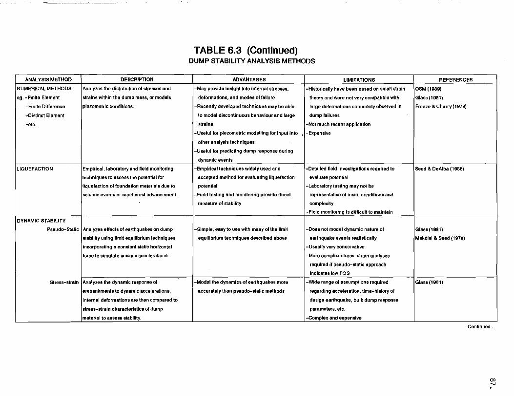
TABLE 6.3 (Continued) DUMP STABILITY ANALYSIS METHODS
ANALYSIS METHOD DESCRIPTION ADVANTAGES LIMITATIONS REFERENCES
NUMERICAL METHODS
ego -Finite Element
-Finite Difference
-Distlnct Element
-etc.
Analyzes the dlstnbutlon of stresses and
strains within the dump mass, or models
piezometric conditions.
-May provide Insight Into Internal stresses,
deformations, and modes of failure
-Recently developed techniques may be able
to model discontinuous behaviour and large
strains
-Useful for piezometric modelling for input Into
other analysis techniques
-Useful for predicting dump response during
dynamic events
, I
-Historically have been based on small strain
theory and were not very compatible with
large deformations commonly observed in
dump failures
-Not much recent application
-Expensive
OSM (1989)
Glass (1981)
Freeze & Charry (1979)
LIQUEFACTION Empirical, laboratory and field monitoring
techniques to assess the potential for
liquefaction of foundation materials due to
seismic events or rapid crest advancement.
-Empirical techniques widely used and
accepted method for evaluating liquefaction
potential
-Field testing and monitoring provide direct
measure of stability
-Detailed field investigations required to
evaluate potential
-Laboratory testing may not be
representative of insitu conditions and
complexity
-Field monitoring Is difficult to maintain
Seed & DeAlba (1986)
DYNAMIC STABILITY
Pseudo-Static Analyzes effects of earthquakes on dump
stability using limit equilibrium techniques
incorporating a constant static horizontal
force to simulate seismic accelerations.
-Simple, easy to use with many of the limit
equilibrium techniques described above
-Does not model dynamic nature of
earthquake events realistically
-Usually very conservative
-More complex stress-strain analyses
required if pseudo-static approach
indicates low FOS
Glass (1981)
Makdisi & Seed (1978)
Stress-strain Analyzes the dynamic response of
embankments to dynamic accelerations.
Internal deformations are then compared to
stress-strain characteristics of dump
material to assess stability.
-Model the dynamics of earthquakes more
accurately than pseudo-static methods
-Wide range of assumptions required
regarding acceleration, time-history of
design earthquake, bulk dump response
parameters, etc.
-Complex and expensive
Glass (1981)
Continued ...

88.
Reliable assessments of foundation conditions and material properties are
fundamental to developing an understanding of potential dump behaviour. Based
on these assessments, and alternative possible dump configurations, a
preliminary evaluation of potential modes of dump instability would be
conducted. Those failure modes identified as being critical to dump stability
would be subject to detailed analysis. Appropriate design criteria would then
be developed based on analysis results, practical mining considerations,
consequences of instability and other factors.
The key step in the analysis stage is the determination of the critical failure
mode (or modes). In many cases, the critical failure mode(s) may be readily
apparent, based on site configuration or material characteristics. However,
where dump configurations or foundations are complex, preliminary analysis of a
variety of failure modes may be necessary to determine which failure mode(s)
controls. Stability charts and other rapid analysis techniques may be
particularly useful for preliminary identification of key failure mechanisms.
Once the key mode of failure has been clearly established, detailed stability
analysis would be carried out using a variety of analytical techniques, as
described below and summarized in Table 6.3. In most cases, the various
analytical techniques appropriate to a given mode of failure yield comparable
results; hence, a variety of equally reliable approaches may be available. For
more complex dumps, comparison of results obtained from different analytical
techniques is recommended, as this approach may provide a more thorough
understanding of dump behaviour, and more confidence in the analysis results.
Where foundation conditions and material properties are complex or poorly
defined, it may be difficult to determine the critical failure mechanism with
confidence. Likewise, some failure mechanisms are less well understood than
others, and available analytical techniques may be very complex and cumbersome,
or may not realistically model the actual failure mode (e.g. complex failures
involving more than one mode of instability, three-dimensional effects,
earthquake induced instability, etc.). In such cases, a conservative approach
to design is necessary, and higher factors of safety, more conservative geometry
and/or strength assumptions than might normally be adopted would be considered

89.
appropriate. In addition, sensitivity analysis or parametric studies of a
variety of possible failure mechanisms often prove helpful in evaluating complex
or poorly understood failure modes, foundation conditions or material
characteristics.
6.4.1 Total Stress vs. Effective Stress
Slope stability analysis can be conducted in two basic ways: Total Stress
Analysis or Effective Stress Analysis. These approaches differ in the way
they deal with internal water forces, and in the way they measure shear
strength. In the total stress approach, only external water forces (i.e.
forces exerted by standing bodies of water, and not pore pressures within
the dump mass) are considered explicitly. Analyses are conducted based on
total unit weights and undrained shear strength parameters. Because a
knowledge of internal pore water pressures is not required for the total
stress approach, it is the only approach applicable in cases where pore
pressures acting on the failure plane are unknown and cannot be reliably
determined. It is also suitable for evaluating short term stability
conditions, where there is insufficient time for induced pore pressures to
dissipate.
Effective stress analyses require a knowledge of the distribution of pore
water pressure along the failure surface, so that the effective stress
(i.e. total stress - pore water pressure) may be calculated. Drained
shear strength parameters are used. The effective stress approach is
generally considered more versatile and more reliable than total stress,
because any total stress condition can be modelled using effective stress,
and effective stress simulates the physical behaviour more closely. The
effective stress approach is particularly suitable in assessing long term
stability, with steady state groundwater conditions.
Most of the analysis techniques described below can be formulated in terms
of either total or effective stresses.

90.
6.4.2 Stability Charts
Stability and bearing capacity charts and tables provide a rapid and
inexpensive method for assessing embankment stability. For small, simple
and low hazard dumps, stability chart solutions may be all that is
required for design. They are also useful for preliminary estimates of
stability or sensitivity, or to check the validity or reasonableness of
results from more complex, rigorous analyses. Charted and tabulated
solutions are available for many of the more sophisticated methods
described below.
It is important to note that stability charts yield approximate solutions
only, and cannot model complex failure modes. Consequently, where
accuracy is important, such as for large or potentially hazardous dumps,
or where complex failure modes occur, stability charts are not recommended
as the only analysis method.
6.4.3 Infinite Slope Analysis
Infinite Slope Analysis is a limit equilibrium analysis which assumes a
planar failure surface at a shallow depth, parallel to the slope face.
The Factor of Safety (FOS) is based on .force equilibrium of a unit width
vertical slice of the failure mass. Moment equilibrium is implicitly
satisfied. Infinite slope analysis is analytically simple, easy to use
and amenable to hand calculations. Seepage forces can be accounted for,
and chart solutions are available.
Infinite Slope Analysis approximates near surface stability only, and is
strictly valid only where the thickness of the failure is negligible in
comparison to the length of the failure plane. Application is normally
restricted to homogeneous slopes.

91.
6.4.4 Plane Failure Analysis
In plane failure analysis, the FOS is based on force equilibrium of the
entire block, which is assumed to be rigid, and moment equilibrium is
implicitly satisfied. The effects of various piezometric surfaces and
tension cracks can also be simulated easily. The analysis is analytically
simple, and amenable to hand calculation or computer solution.
As with other limit equilibrium analyses, this model assumes that the
ratio of available shear strength to shear stress is the same everywhere
along the failure surface. Furthermore, this model provides no
explanation of internal deformations which are commonly observed in
conjunction with overall failure.
6.4.5 Wedge Failure Analysis
For wedge failure analysis, the blocks comprising the upper portion of the
failure mass are considered to be in a state of limiting equilibrium. The
block forming the toe of the slope supports the upper blocks. The
equations of equilibrium are used to resolve the net driving force
imparted to the toe block by the upper active or sliding blocks. FOS is
then based on the resistance of the toe block to sliding along its base.
Some wedge analysis formulations consider both force and moment
equilibrium, while others consider force equilibrium in one or two
directions only.
Wedge failure appears to model some types of dump behaviour very well,
especially the case where dumps are located on steep slopes with a veneer
of relatively weak soils forming the foundation. The models are
analytically relatively simple and amenable to hand calculations or
computer methods. Chart solutions are available for some models, making
parametric studies relatively easy. In addition, the analysis may be
generalized to three dimensions (Golder Associates, 1987).
.i

92.
In common with methods of slices, wedge analyses require some assumptions
regarding inter-block forces to render them statically determinant. Also,
the FOS calculated by these methods is based on a relatively small portion
of the failure surface, unlike most limit equilibrium methods, which base
the FOS on the shearing resistance of the overall failure plane.
Consequently, caution must be used when interpreting results or comparing
them with results from other methods.
6.4.6 Slip Circle Analysis
Slip circle analyses assume the failure plane to be a circle or
logarithmic spiral, and the failure mass to behave as a rigid body which
rotates about the centre of curvature. The Swedish Circle Method, also
referred to as the 0=0 Method, assumes the shear strength to be due to
cohesion alone. FOS is based only on moment equilibrium. The Friction
Circle Method assumes all forces are concentrated at a single point on the
failure surface. FOS is based on all three equations of equilibrium. The
Log Spiral Method assumes no cohesion, and FOS is also based on moment
equilibrium. All three of these methods explicitly or implicitly satisfy
all conditions of static equilibrium.
Slip circle methods are analytically simple, are amenable to hand
calculation or computer analysis and provide a useful tool for preliminary
estimates of stability and sensitivity. The Friction Circle Method
provides a lower bound, conservative assessment of FOS for limit
equilibrium methods. The 0=0 condition for the Swedish Circle Method
restricts its use to total stress analysis of cohesive foundations or
embankments. All three methods are limited to homogeneous slopes, and
provide only approximate solutions. These methods should not be used as
the only analysis technique for large, complex or potentially hazardous
dumps.

93.
6.4.7 Methods of Slices
General
Methods of slices are limit equilibrium techniques whereby the failure
mass, defined by a general slip surface, is divided into a number of
slices. The equilibrium of each slice is considered individually, and a
FOS is generally based on the sum of the shear stresses and available
shear strength on the base of each slice. Methods of slices can simulate
a wide variety of failure surface shapes, embankment configurations and
non-homogeneous slopes. They are a widely used, understood and accepted
approach to engineering analysis of slopes. Methods of slices also
provide a more rational assessment of the normal stresses along the
failure surface than more simplistic methods, such as slip circle
analysis, and provide some explanation of internal deformations within the
failure mass.
Some assumptions regarding internal stress distributions are required to
render the analyses statically determinant. These methods tend to be
analytically complex, and hand calculations are usually tedious or
impractical; however, a variety of easy to use computer programs are
commercially available for many of the more common methods of slices.
Problems with convergence of iterative solutions sometimes limit their
usefulness. For purposes of discussion, methods of slices are divided
into two basic groups: Simplified Methods and Rigorous Methods.
Simplified Methods
Simplified methods, such as the Ordinary Method of Slices (OMS), Bishop's
Simplified Method, and various force equilibrium methods, do not satisfy
all conditions of static equilibrium. OMS neglects inter-slice forces,
which allows direct calculation of a unique FOS. Bishop's Simplified
Method neglects inter-slice shear forces, and requires iteration to solve
for FOS. Force equilibrium methods neglect moments, and also require
iteration to reach a result.

94.
In comparison to more rigorous methods, simplified methods are relatively
quick and easy to use, and can be solved using hand calculations, though
these tend to be tedious and not very efficient. Simplified methods are
commonly accurate to within 10 to 15% of the more rigorous methods, which
in many cases may be all the accuracy that is needed or significant.
Simplified methods are also useful for preliminary assessments of
stability and sensitivity, and as a check on the validity of results from
more detailed calculations.
In some cases, such as with OMS when pore pressures are high or slopes are
flat, results tend to be overly conservative. In addition, OMS is
suitable only for total stress analysis. Also, convergence problems may
be experienced with Bishop's Simplified Method where failure surfaces are
very steep.
Rigorous Methods
Rigorous methods, such as those of Janbu, Spencer, Morgenstern-Price and
Sarma, satisfy all conditions of static equilibrium. Variations between
the methods are generally related to assumptions regarding the treatment
of inter-slice forces. All of these methods require iteration to reach a
solution, and values of FOS calculated by the various methods are usually
within about 5% of one another.
Because they satisfy all conditions of static equilibrium, rigorous
methods provide implicitly more realistic models of the physical mechanics
of failure than simplified methods. Through informed selection of
analysis parameters, a wide variety of internal stress conditions can be
modelled. Although not practical for hand calculations, computer programs
are available for detailed parametric studies.
Rigorous methods are more complex, costly and difficult to use than
simplified methods. Selection of modelling parameters and interpretation
of results require a detailed understanding of the analytical basis and

95.
assumptions each method employs. Except for Sarma, these methods are
restricted to simulating the failure mass using vertical slices.
6.4.8 Y=Q Method
The Y=Q Method is a method of slices analysis technique which can be set
up with the same inter-slice force assumptions made in Bishop's, Janbu's
or Spencer's methods. It analyzes the distribution of shear stresses
along the selected failure surface to determine which portion of the
failure surface is in a condition of limiting equilibrium. It provides
the same results as the other methods of slices, as well as an
understanding of the inter-slice force distribution. The method thus
provides some insight into the likely internal deformations of the failure
mass, and the possible locations of tension cracks or failure scarps.
This technique is relatively simple and useful in the design and
interpretation of monitoring programs. Furthermore, the Y=Q Method is
well suited for probability of failure assessments.
6.4.9 Numerical Methods
Little information is available in the literature regarding the recent
application of numerical methods of analysis, such as Finite Element,
Finite Difference, Distinct Element, and others, to the analysis and
design of mine dumps. Historically, these methods have been based on
small strain theory, which is generally not compatible with the large
strains commonly observed during dump failure. In addition, such methods
require a detailed knowledge of the stress-strain behaviour of the dump
materials, which is generally not available. Finite element and finite
difference techniques have also been successfully utilized to evaluate
dynamic response of embankments to earthquakes (Glass, 1981).
Recent developments in numerical analysis have seen the formulation of
codes which can simulate discontinuous behaviour and large strains, such
as the Universal Distinct Element Code (UDEC). Based on these recent

96.
developments, it is possible that numerical analysis may become a useful
tool for mine dump design in the future.
Another area where numerical methods might be applied indirectly to mine
dumps is in predicting piezometric conditions. Numerical seepage analysis
techniques are available using the finite element or finite difference
approaches (Freeze and Cherry, 1979), and this technology has been used
extensively in analysis of dams and tailings impoundments.
6.4.10 Liquefaction Analysis
As indicated in Section 6.3.5 above, analysis of liquefaction potential
due to earthquakes is commonly carried out using empirical methods based
on in situ density of liquefaction susceptible soils (e.g. Seed and De
Alba, 1986). Assessment of liquefaction potential due to high pore
pressures generated by rapid loading or crest advancement is usually based
on laboratory determination of pore pressure generation and dissipation
rates and field monitoring of test fills or trial dumps.
6.4.11 Dynamic Stability Analysis
Techniques for analyzing the stability of embankments subjected to dynamic
loading (e.g. earthquake) can generally be divided into two types:
pseudostatic techniques and stress-strain techniques. Pseudostatic
analyses are usually conducted using conventional limit equilibrium
analysis techniques, such as those described above, which have been
modified to incorporate a constant horizontal destabilizing force to
represent the effects of the earthquake. The magnitude of this force is
usually determined on the basis of a seismic risk evaluation of the site
(see Section 3), which provides expected earthquake magnitudes and ground
accelerations (i.e. seismic coefficients) for specific return periods
(e.g. 1:50 year event, 1:200 year event, etc.). Pseudostatic analysis
techniques are described in some detail by Glass (1981) and Makdisi and
Seed (1978).

97.
Because earthquakes are dynamic events, with directions and magnitudes of
ground accelerations varying throughout their duration, pseudostatic
analyses do not provide a very good model of the physical conditions.
Where pseudostatic assessments are based on anticipated peak ground
accelerations, they tend to yield very conservative results.
Dynamic stability analyses based on stress-strain techniques generally
provide a more realistic view of the impact of seismic events. However,
these methods tend to be much more complex than simple pseudostatic
approaches, and require a variety of assumptions regarding the
acceleration time-history of the design earthquake event and a variety of
parameters to model foundation and dump response. In general, dynamic
techniques are designed to assess the amount of internal deformation which
can be expected during an event. This deformation is then assessed in
terms of the shear strength characteristics (i.e. peak and residual shear
strength vs. shear strain and shear stress) to determine the likelihood of
overall failure of the embankment. A good discussion of dynamic analysis
techniques is given in Glass (1981).
The common practice for mine dumps in British Columbia has been to first
evaluate static stability using limit equilibrium techniques as discussed
above. This would be followed by pseudostatic analysis to gain an initial
appreciation for the potential for instability due to seismic events. If
the results of pseudostatic analysis indicate low factors of safety
(i.e. less than about 0.9 to 1.0, depending on the assumed seismic
coefficients), more complex (and costly) dynamic analyses will be
required. No guidelines have previously been provided for selecting an
appropriate seismic coefficient for pseudostatic analysis. The
recommended approach is to conduct analyses for a variety of possible
ground accelerations to assess the sensitivity of the design to earthquake
events. To evaluate the need for further dynamic analyses, seismic
coefficients based on current Canadian seismic risk zoning and peak
acceleration predictions (i.e. 10% probability of exceedance in 50 years)
outlined in Weichert and Rogers (1987) are considered appropriate.

98.
6.5 INTERPRETATION OF STABILITY ANALYSIS RESULTS
Two basic approaches are available for assessing the results of stability
analysis: deterministic approaches based on evaluation of the Factor of Safety,
and probabilistic approaches based on assessing the Probability of Failure.
6.5.1 Factor of Safety
The classical approach to evaluating the stability of slopes is to
calculate a Factor of Safety. For most limit equilibrium types of
analysis, the FOS is commonly defined as the ratio of the available shear
strength along the most critical failure surface, to the shear stress
along that surface. Definitions of FOS may vary, depending on the
analysis method (e.g. ratio of driving forces to resisting forces, ratio
of overturning moments to restoring moments, etc.). However, provided
they reflect the fundamental ratio of available shear strength to shear
stress over the whole failure surface, FOS calculated from different
methods can be compared.
In determining the appropriate factor of safety for a given design case,
several factors must be taken into consideration, including:
The degree of uncertainty in the shear strength parameters
The variability of material composition (e.g. proportion of fines)
The variability of foundation conditions and geometry
Short term (i.e. during construction) vs. Long Term (i.e. final
reclamation slopes)
Consequences of failure
The type of analysis technique utilized, its inherent conservatism
and how well the method models the physical conditions
The importance of field control during operation of the dump
Many of these factors are subjective, site specific or cannot be
determined with confidence. Consequently, it is considered unduly
restrictive to establish specific FOS criteria which must be met in all

99.
design cases. Selection of a reasonable design factor of safety should be
based on sound engineering judgement, with careful consideration given to
the ramifications if assumptions prove to be incorrect.
Guidelines for FOS reported in the literature (e.g. Duncan and Buchignani
and DeWet, 1987; MESA, 1986; and USBM, 1982) range from FOS = 1.0 for
transient conditions, such as earthquakes where the consequences of
failure are low, to greater than 2.0 for dumps founded on problem soils or
where consequences of failure are severe. In the case of stability of the
dump face, where frictional materials are at their angle of repose, the
FOS is usually considered to be 1.0 for shallow, near surface failures.
Suggested guidelines for minimum FOS design values for mine dumps in
British Columbia are given in Table 6.4.
6.5.2 Probability of Failure
Probabilistic approaches are based on the premise that critical parameters
in the stability analysis are subject to variability, and that variability
can be modelled using statistical techniques. Uncertainty in the values
of critical parameters can be translated into variations in the FOS, which
can also be modelled statistically. The probability of the FOS being less
than 1.0 is then a statistical measure of the likelihood of slope
instability. Probabilistic analyses of slope stability are described by
Bosscher et al (1988). Caldwell and Moss (1981) illustrate the
application of Probability of Failure analysis to dump design using the
y=o Method described above.
Probabilistic methods require an additional step in the stability
assessment and design process. In most cases, sufficient information on
the variability of key material properties is unavailable. As a result,
probabilistic approaches to dump design have received little attention
from industry to date, and no documented case histories were noted in the
literature. However, statistical approaches such as probabilistic

100.
TABLE 6.4 INTERIM GUIDELINES FOR MINIMUM DESIGN FACTOR OF SAFETY 1
STABILITY CONDITION
STABILITY OF DUMP SURFACE
SUGGESTED MINIMUM DESIGN VALUES FOR FACTOR OF SAFETY
CASE A CASE B
-Short Term (during construction)
-Long Term (reclamation - abandonment)
OVERALL STABILITY (DEEP SEATED STABILITY)
-Short Term (static)
-Long Term (static)
-Pseudo-Static (earthquake) 2
1.0
1.2
1.3 - 1.5
1.5
1.1 - 1.3
1.0
1.1
1.1 - 1.3
1.3
1.0
CASE A: -Low level of confidence in critical analysis parameters -Possibly unconservative interpretation of conditions, assumptions -Severe consequences of failure -Simplified stability analysis method (charts, simplified method of slices) -Stability analysis method poorly simulates physical conditions -Poor understanding of potential failure mechanism(s)
CASE B: -High level of confidence in critical analysis parameters -Conservative interpretation of conditions, assumptions -Minimal consequences of failure -Rigorous stability analysis method -Stability analysis method simulates physical conditions well -High level of confidence in critical failure mechanism(s)
NOTES: 1. A range of suggested minimum design values are given to reflect different levels of confidence in understanding site conditions, material parameters, consequences of instability, and other factors.
2. Where pseudo-static analyses, based on peak ground accelerations which have a 10% probability of exceedance in 50 years, yield F.O.S. < 1.0, dynamic analysis of stress-strain response, and comparison of results with stress-strain characteristics of dump materials is recommended.

101.
analysis are well suited to cost-benefit studies, and it is likely that
more attention will be given to such approaches in the future.
6.6 SETTLEMENT
As a result of the material characteristics and the construction methods
commonly in use, mine dumps are subject to substantially greater settlements
than most other types of engineered embankments. The potential for disruption
of drainage and crack formation due to differential settlement is large and must
be taken into account when designing covers for dumps. For comparison,
settlement of dams constructed using dumped rock fill (reported by Clements,
1984) is of the order of a few percent of the overall height. OSM (1989)
suggests that for planning drainage measures, estimates of settlement based on
1% of the dump height are appropriate.
As a result of potential differential and total settlement of dumps and dump
foundations, few structures which are sensitive to settlement are constructed on
mine dumps. In cases where structures are to be located on waste, specific
construction measures should be undertaken to limit potential settlements (e.g.
compaction, controlled lift thickness, etc.), or construction of the structure
might be delayed until settlements have ceased. In this regard, documentation
of settlements is essential.
6.7 FAILURE RUNOUT
A comprehensive mine dump design must recognize that failures might occur, and
provide for mitigative and/or protective measures to reduce the impact of
failures to an acceptable level. As discussed in Section 5.4, assessment of
risk and rational design of mitigative measures requires an understanding of the
runout characteristics of potential failures. The only methods currently
available for runout analysis involve empirical correlations (e.g. Golder
Associates, 1987). However, as indicated in Section 1, research into runout
prediction is currently being sponsored by EMRC. Results of that study will be
incorporated into an updated version of these guidelines.

102.
7. CONSTRUCTION
7.1 FOUNDATION PREPARATION
Depending on results of field investigatio~s, materials testing and stability
analyses, specific measures may have to be taken to improve marginal or poor
foundations to ensure that in situ conditions meet or exceed analysis and design
assumptions. Foundation preparation measures which may be required include
clearing, stripping or removal of poor or weak soils, installation of specific
underdrainage measures and pre10ading of the site. Each of these measures and
their application are described in the following paragraphs.
In general, where foundation conditions are poor, soils are soft, very wet or
weak, the recommended approach is to choose a more favourable site. Where other
sites are not available or cannot be economically developed, measures to improve
foundations conditions as described below may be the only practical alternative.
7.1.1 Clearing
Logging and/or clearing of the vegetative cover is not normally required.
In many cases, the process of clearing or logging may disturb and weaken
underlying soils; hence, clearing could have a negative impact on overall
dump stability.
Where a site is forested, it may be a requirement to log merchantable
timber. If so, logging of slopes should be performed in as short a time
as possible in advance of dumping so as to minimize the exposure period of
the devegetated ground. Clearing of the site would also be required if
stripping of organic or weak overburden soils is required. On steep,
heavily vegetated slopes, where vegetation could form a continuous weak
mat or zone beneath the dump, partial clearing may also be required.
Portions of the dump foundation which are planned to convey water should
generally be cleared of vegetation and organic overburden to ensure
adequate hydraulic performance.

103.
7.1.2 Stripping
If thick (i.e. >1 to 2m) soft organic soils or muskeg deposits underlie a
dump, particularly where foundation slopes are steep, it may be necessary
to remove them. If stripping is required, special care must be taken to
ensure that the excavated surface is sufficiently dense to support the
dump load. Proof rolling of the excavated surface may be necessary to
achieve this objective. Grading and drainage of the stripped surface may
also be required to prevent accumulation of water and softening of
foundation soils.
Where soft soil deposits are thin, or where it can be reliably
demonstrated that the process of dump advancement will displace or
sufficiently consolidate weak foundation soils, removal or other remedial
measures (e.g. prelifts) may not be required. In such cases, field trials
will be required to confirm the feasibility of leaving soft soils in
place.
7.1.3 Underdiainage
In areas of groundwater discharge, saturated soils may be too soft to
support a fill of significant height. In this situation, excavation of
the soil may be ineffective, and even counterproductive, if equipment
tracking over the wet areas remoulds and weakens the underlying soils. A
better method of foundation preparation may be to construct finger drains
of sand and gravel, typically in a herringbone pattern, to collect water
from a wide area beneath the dump and direct it into a single collector
ditch.
Underdrains may consist of either or both gravel filled trenches and
gravel blankets. Where seepage rates are high, perforated steel pipes may
be installed in trenches to increase the hydraulic capacity. A formal
rock drain may be required at the base of a valley dump where significant

104.
flow occurs through the dump site. Design considerations for rock drains
are discussed in Section 7.2.2.
In all cases where underdrainage measures are proposed, the short and long
term benefits and performance must be evaluated at the outset and
confirmed through monitoring.
7.1.4 Prelifts
Where soil conditions are too soft and wet to support equipment for
stripping or excavating drainage trenches, an alternative means of
foundation preparation and protection is to place a prelift of dump
material to consolidate and/or span or contain weak soils. Prelifts
typically range between 5 and 15m in thickness. The ability to construct
a prelift requires that access be available into the area of concern,
which is frequently in the toe region of the dump. Developing access into
the toe area of many dumps is often difficult and costly; hence, prelifts
tend not to be utilized extensively.
7.2 SURFACE WATER AND SNOW CONTROL
7.2.1 Diversions and Runoff Control
Mine dumps frequently cover a large surface area, and measures are
required to control runoff water to prevent saturation of exposed slopes,
prevent development of phreatic surfaces within the dump, protect against
loss of fines from the dump material by piping, and minimize surface
erosion or development of flow failures on dump surfaces.
Surface water from catchment areas outside the dump and runoff from direct
precipitation on the dump surface should be collected and diverted around
the dump, or conveyed through the dump in a properly engineered and
constructed rock drain. Diversions are often feasible for Sidehill and
Heaped dumps, but are usually difficult to incorporate into Valley or
Cross-Valley fills, unless topography and stream gradients are such that

105.
the majority of stream flow can be intercepted upstream of the dump and
channelized on the valley wall beside the dump. Sidehill diversions are
generally not favoured because of the need for regular maintenance, which
can make them unsuitable for continued use after dump completion.
In large dumps, where there is concern for toe stability if pore pressures
are allowed to buildup within the fill, it is recommended that the dump
surface be sloped away from the crest at a slight gradient (1 to 2%), to
direct runoff into a ditch at the rear of the dump platform. To be
effective, the ditch must discharge into another subcatchment out of the
dump site catchment, or into a rock drain.
7.2.2 Flow-Through Rock Drains
Construction of flow-through rock drains for mine dumps provides dump
designers with a viable, economic alternative to costly and often
difficult to maintain surface water diversions. However, it is important
to note that no long term experience with rock drains is currently
available. Clearly, additional research, field trials and documentation
of long term performance is essential.
The following discussion is not intended as a comprehensive treatment of
rock drain design, and is provided as an overview of the important factors
which must be considered in rock drain design. Because flow-through rock
drain technology is relatively new, and the state-of-the-art is changing
rapidly, rock drain designers are cautioned to refer to the most current
literature.
In the past decade, the practice of conveying surface flows through mine
dumps by means of rock drains has gained general acceptance for flows up 3/s.to about 20 m Applications to construct dumps with rock drains to
convey larger flows, of 30 m3/s or more, are currently being evaluated for
several coal mines in British Columbia and Alberta.

106.
In analyzing flows through a completed rock drain, three conditions are of
primary interest and warrant detailed analysis. These are: the capacity
of the inlet, flow conditions in the outlet, and contingency for overflow
in the event that the extreme flood flow exceeds the capacity of the drain
(Das et aI, 1990).
Inlet Capacity
The capacity of the drain inlet to transmit water is controlled by the
dump slope, valley side slopes, dump height, amount and nature of
sediments accumulating upstream of the inlet, and potential obstructions,
such as may be formed by debris from landslides and organic materials. In
the long term, the possibility that stream alluvium, which would normally
be transported downstream during the freshet and storm events, will
completely fill the headpond above the dump should be examined, and the
impact on long term performance of the dump evaluated.
Outlet Flow
The most vital component of a rock drain design is the drain outlet. The
outlet should be capable of transmitting at least the 200 year flood flow
without compromising the stability of the final dump slope. Where the
consequences of instability of the dump are severe, the maximum probable
flood may be an appropriate design level. Alternatively, appropriately
designed overflow channels could be incorporated into the design.
Design aspects to be considered .are the final geometry of the slope, the
height of the seepage face predicted to occur on the slope during the
flood event, seepage forces which could destabilize the slope, and scour
forces at the outlet which could undermine the toe. In addition,
environmental effects downstream of the dump, including potential scouring
of downstream facilities such as bridges and piers, should be assessed. A
procedure for calculating rock drain capacity, including outlet flow, is
presented by Leps (1973) and applied to an actual rock drain by Claridge,
et al (1986).

107.
Overflow Channel
It may be desirable to provide an overflow channel in the event of extreme
flood flows, future blockage of the inlet to the rock drain, or in
anticipation of voids plugging with fines. The function of an overflow
channel is twofold:
i) it will serve to channelize flow which is not absorbed into the
inlet, in a location where it will then have the opportunity to seep
downwards through the mine dump into the rock drain;
ii) the channel can be designed to function much as a spillway for a
dam, to direct flows in a controlled manner such that the integrity
of the downstream portion of the dump is not compromised during the
flood event.
7.2.3 Snow Control
It has been observed at dumps in operation at coal mines in the Rocky
Mountains that rotational or non-rotational type failures frequently occur
during the late spring and summer. From back analysis of such failures,
it has been concluded that residual snow and ice concentrations from the
previous winter, in combination with relatively fine dump materials, may
have been responsible for some of the failures. The snow and ice may melt
rapidly and, if present in a continuous layer, could form a weak zone.
Also, excess pore pressures may develop, which cannot readily be
dissipated in the fine dump material.
To minimize the effect of snow on dump stability, the following general
guidelines should be followed, where appropriate:
a) Dump materials should not be placed on dumping faces where the depth
of snow is significant (i.e. >lm). The dump surface should be
worked evenly so that there are no large depressions that may infill
with snow.

108.
b) Snow removed from the mine should not be disposed in an active dump.
A separate dumping area should be provided where consequences of
instability, avalanches, etc. are minimal. In this regard, it may
be convenient to designate one dump as a snow-only dump during
winter operations.
c) Snow should not be disposed in drainage courses or gullies which
will be covered by dump materials.
d) Dump development should be planned such that winter dumping is on
windward exposed faces, where accumulations of snow will be the
least.
7.3 CONSTRUCTION METHODS
7.3.1 Platforms and Lifts
Many of the larger mine dumps have been developed in thick lifts via a
series of platforms spaced at vertical intervals of 10m or more (see Fig.
7.1). Platform elevations are set to minimize the vertical haul required.
Dump stability may be enhanced by controlling the width and length of the
platforms and the vertical spacings between them. If space is available,
wide platforms may permit berms to be maintained at the platform
elevations, resulting in a benched slope with a relatively flat overall
slope angle. Closely spaced platforms and thin lifts also reduce the
amount of loading imposed in one increment. This can be an important
factor where the dump is supported on saturated soils which generate pore
pressure when loaded.
7.3.2 Ascending vs. Descending Construction
Ascending and descending construction methods are illustrated in Fig. 7.1.
Ascending or upward construction is preferred, because each successive
lift is supported on a previously constructed lift, the behaviour of which

BERM (TERRACE)
7
REPOSE <J' ANGLE..SLOPE ~---- LIFT SEQUENCE
REPOSE ANGLE SLOPE
109.
a) Ascending Construction with Terracing
INITIAL PLATFORM
SLOPE «REPOSE)
SUBSEQUENT WRAP-AROUND LIFTS
b) Descending Construction with Wrap-arounds
FIG. 7. 1 ASCENDING vs DESCENDING CONSTRUCTION

110.
may be well documented and understood. Any failure surface will have to
develop through the previously constructed lift, which also acts as a bu
ttress for the toe and provides some confinement for foundation soils.
Another advantage of ascending construction is that the toe is always
supported on level ground (i.e. the previous platform).
In most open pi~ mines, the pit is initiated at a relatively high
elevation and mining proceeds downwards. Consequently, economics dictate
a level haul onto a series of platforms which are constructed at
successively lower elevations (descending construction). In this case,
foundation conditions and ground slopes in the toe region frequently
control stability.
7.3.3 Material Distribution and Crest Advancement
In planning a dump, thought should be given to incorporating some
redundancy into the number of dumping sectors which can be activated, as
well as to maximizing the length of dump crest in each area. The benefits
of doing this are twofold. First, if a failure occurs in one dump sector,
or the rate of crest subsidence is excessive, operations in that part of
the dump can be suspended until stable conditions resume. Second, by
dumping over as long a crest length as possible, the rate of advance of
the dump can be minimized. This will reduce the rate of loading on the
foundations and the corresponding generation of pore pressures in the toe
region. Also, a slow rate of filling allows more time for the dump
materials to consolidate and gain frictional strength.
Because of the wide range of factors which influence stability (see
Section 5), dumps tend to exhibit unique behaviour. Hence, it is
difficult to determine limiting placement rate criteria at the design
stage. Initial dumping rates and crest advancement should be
conservative. Monitoring of dump behaviour is critical to be able to
verify the appropriateness of dump advancement rates assumed for design,
and to modify construction criteria as necessary.

111.
7.3.4 Topographic Factors
Variations in ground slopes beneath advancing dumps frequently control
dump stability during construction. Dump development should be planned to
take maximum advantage of topographic diversity. Where dumps must be
advanced over steeply sloping ground, several steps may be taken to
minimize the risk of instability as follows:
initiate a fill over steep slopes by dumping into a gully where
slopes are lower, and three-dimensional confinement improves
stability;
design the toe of the lift to be supported on natural benches or the
flattest available topography;
after the initial fill has been keyed onto flatter topography,
extend the dump in a direction parallel to the contours;
individual gullies crossing a steep slope should be filled in by
dumping along the gully axis. This approach will avoid having to
cross steep gully side slopes, and will also tend to promote natural
segregation of coarse rock in the bottom of the gully, improving
underdrainage.
The recommended sequence for development of mine dumps over steep
topography is illustrated in Fig. 7.2.
7.3.5 Terraces and Wrap-Arounds
~erraces and wrap-arounds provide a sound approach to mine dump design,
and can simplify and expedite reclamation. Terraces are generally
associated with ascending construction, and result when succeeding lifts
do not extend to the crest of the previous platform, thus maintaining a
berm. Berms may be left at all platform elevations or just selected ones.
Figure 7.1a illustrates the concept of terracing.

112.
i) Inili.le dumping in we. of fl.llesl slopes, ulilizing gullies 10 m.ximize confinemenl.
•>
i) Adv.nce dump in • direclion perpendic.... 10 conlours
unlil dump is keyed onlo fl.lter lopogr.phy.
iii) Extend dump ......Iel 10 lhe conlours.
FIG. 7.2 RECOMMENDED SEQUENCE FOR ADVANCEMENT OF DUMPS OVER S"rEEP TERRAIN

113.
Wrap-arounds are generally associated with descending construction, and
are configured to enclose and buttress the lifts which have previously
been dumped at higher levels. Platforms or berms are typically located at
vertical intervals of 20 to 40m, and may be graded downwards, in the
direction of advance. The width of each platform or berm is determined on
the basis of disposal capacity requirements, stability considerations and
slope conditions at the toe of the slope (Section 7.3.4). Figure 7.1b
illustrates the concept of wrap-arounds.
7.3.6 Buttresses and Impact Berms
In cases where potential hazards prohibit or restrict dump construction,
it may be feasible to improve dump stability via the use of buttresses.
Alternatively, establishment of hazard mitigation or protection works may
render the site useable. Mitigative works usually consist of impact or
deflection berms and debris basins or chutes. Design requires careful
consideration of site specific conditions, as well as an assessment of the
size and runout characteristics of potential failures. In some instances,
the optimum solution might be to relocate facilities which may be
endangered by possible instability.
In steeply sloping terrain, where the safety factor against a foundation
failure is low, the potential for a long runout may be high. If potential
damages associated with failure are unacceptable, one protective measure
may be to construct a containment structure or buttress in the form of a
ring at approxi~ately the location of the ultimate toe of the dump. A
buttress is considered to be an integral part of the dump toe. The design
of the buttress is based on increasing the factor of safety to a specified
design value, and is essentially a matter of configuring the toe zone to
incorporate as much mass as possible to counterbalance the driving forces
of the upper portion of the dump.
Impact berms are usually located downslope of the final toe on flatter
topography, where they can best function to intercept both individual

114.
boulders and slides, and to protect facilities or a stream course below
the dump. The design of impact berms is more complex than buttresses, as
they must be of sufficient mass and height to prevent a failure runout of
a specific size from crossing them. Impact berms may be very effective in
mitigating runout problems associated with small slides and flows.
However, constructing impact berms of sufficient mass and height to
significantly mitigate major dump failures is usually impractical. Figure
7.3 illustrates typical configurations for a buttress and impact berms.
7.3.7 Control of Material Quality
One of the most effective means of improving dump stability is to exercise
control over the quality of material placed in critical parts of the dump.
When dumping on steeply sloping terrain, only coarse, durable rockfill
should be placed into gullies or defined water courses. It is also
beneficial to place coarse rockfill directly onto steep slopes (i.e.
slopes exceeding 25° to 30°) to improve the frictional contact between the
fill and the foundation, to provide underdrainage and to mobilize as much
strength as possible near the bottom of the dump.
Low quality, friable, fine grained materials should be placed in the upper
portions of the dump, where the material is not exposed to significant
runoff flows. Highly weathered, decomposed rock and soil should be spread
in lifts on individual dump platforms, rather than down the dump face. If
possible, soil and fine rockfill should be mixed with the coarser waste,
or placed on the top of the final dump for use in reclamation. Fine dump
materials should be placed in thin lifts and compacted with haul trucks to
improve stability and strength. If placement of degradable rockfill
materials onto an active dump is unavoidable, it should be dumped along
with as much good quality coarse rock as possible.
Another approach to dealing with poor quality dump materials is to dispose
of them in cells within the dump. Cells should be incorporated in the
dump in an organized fashion such that they do not form a potential
failure zone.

115.
/ /
/@/
/ /
/
G) ---\--- -_ - - SUP SURFACE -SOFT SOIL
a) Toe Buttress
ORIGINAL GROUND SURFACE
REPOSE
SLOPE '"
IMPACT BERM ~ w \wa: (J
Q w REPOSEtc SLOPE " (J
9 wa:
b) Impact Berm
FIG. 7.3 TOE BUTRESS AND IMPACT BERMS

116.
7.3.8 Winter Construction
Where a dump has only marginal stability, and the risk of a failure with a
long runout is not acceptable, particular attention should be given to the
effect that incorporation of snow and ice into the dump mass may have on
its stability. If a dump site is located in a leeward aspec~, which is
prone to large snow accumulations, it may be best to suspend dumping in
this area during winter. As a general guideline, dumping is not
recommended when there is in excess of 1m of snow on the dump surface.
This guideline may be relaxed if coarse, competent rockfill is dumped onto
the snow, or if it can be demonstrated that the rock displaces the snow
without incorporating snow and ice in distinct layers into the dump.
Further discussion of snow control measures is provided in Section 7.2.3.
7.3.9 Restricted Operation
Dump performance should be monitored both visually and with instruments,
in accordance with procedures outlined in the companion report on
monitoring guidelines (Klohn Leonoff, 1991). Mine wide criteria should be
developed on the basis of the performance history experienced for all
dumps, and should be used to determine when restrictions need to be
imposed on the dumping operation. Restrictions include suspension or a
reduced rate of dumping and the use of select, coarse rock. Reduced
dumping rates are usually imposed when dump deformation rates exceed a
specified amount per hour, or per day.
7.3.10 Trial Dumping
At sites where dump stability is difficult to predict with confidence, the
initial stages of dumping should proceed on a trial basis to permit
verification of the design assumptions. For example, soft foundations may
be susceptible to excess pore pressure generation, thus necessitating that
the rate of dumping be restricted to a prescribed level. An allowable
rate of dumping may be established based on a conservative interpretation
of strength and consolidation data.

117.
Pore pressure generation and dissipation rates are very difficult to
predict accurately on the basis of laboratory testing alone. Hence, pore
pressure sensors should be installed in the foundation of susceptible
dumps to permit preparation of a pore pressure model which reflects actual
measurements. To generate the data required to develop the model, the
trial dump may be constructed in increments, allowing sufficient time
between loading stages for pore pressure trends to be established.
7.4 DESIGNING FOR RECLAMATION
The Mines Act and Health, Safety and Reclamation Code (MEMPR, 1989) requires
that dumps be reclaimed. The primary objectives of dump reclamation are to:
i) maintain long term stability;
ii) maintain long term erosion control;
iii) ensure that water released from the dump to the receiving environment is
of an acceptable quality; and
iv) to ensure that land use and productivity objectives are achieved.
As indicated earlier, short term stability and design considerations may not be
the same as long term, abandonment requirements. However, there may be distinct
advantages to designing the dump with reclamation in mind from the outset. Such
advantages could include lower overall reclamation costs, improved short term
stability and fewer operational problems.
Long term erosion control is a function of the steepness of dump slopes, the
durability of dump materials, and surface runoff collection. Regrading of
angle of repose dump slopes and/or provision of berms and runoff collection
ditches may be necessary to prevent erosion. Limiting the height of repose
angle slopes and providing periodic berms simplifies implementation of erosion
control measures.
Most dump materials tend to be reasonably well graded and self-filtering.
Consequently, seepage flows released from dumps tend to be relatively free of

118.
suspended sediments. The main concerns with seepage water quality are heavy
metal contamination or acid rock drainage. Special provisions for encapsulation
of potential contaminants within other neutralizing materials or low
permeability envelopes may be required. Alternatively, it may be more efficient
to treat seepage flows to reduce effluent contaminants to acceptable levels, and
rely on contaminant levels reducing naturally with time to acceptable levels.
In any event, the long term impact of disposal of potentially reactive dump
materials requires careful consideration and planning during the initial design
phase. Details regarding evaluation and long term mitigation of potentially
reactive dump materials are given in B.C. AMD Task Force (1990).
Land use and productivity objectives need to be clearly identified at the outset
of the project, and realistic plans developed to achieve them. As for long term
stability and erosion control, incorporation of land use planning with dump
design may simplify and reduce the costs of achieving land use objectives.
For additional discussion regarding reclamation requirements, the reader is
referred to MEMPR (1990).
7.5 UPDATING DESIGN BASED ON PERFORMANCE
As discussed in Section 2 above, mine dump design is an iterative process.
Rational implementation requires that designs be initiated, monitored and
revised based on the documented performance. This process is particularly
important because of the wide range of unknowns the mine dump designer must deal
with, and potential impacts if the design assumptions prove to be incorrect.
Mine planners should make specific provisions for monitoring and evaluating dump
performance, and for updating and revising dump plans on a regular basis.

119.
8. ACKNOWLEDGEMENTS
Many individuals and organizations participated in this study, and their
contributions are appreciated. In addition to the various mines responding to
the mine dump questionnaire, who are listed in Appendix A, written contributions
were received from: J.C. Errington, MEMPR; L. Bolt, USBM; J. Purkis, Minnova
Inc.; D.S. Cavers, Hardy BBT Ltd.; D. Fawcett, Smoky River Coal Ltd.; and R.
Jeria, Westar Mining. The authors also express their appreciation to Mr. R.W.
McGinn and Mr. T. Vaughan-Thomas of MEMPR for their assistance with coordinating
the study and for their guidance. Reviews and editorial comments provided by
the B.C. Mine Development Steering Committee and technical reviewers are
acknowledged with thanks.

120.
9. ANNOTATED BIBLIOGRAPHY
American Society for Testing Materials (ASTM). Annual Book of ASTM Standards, Part 19. Testing Specifications
Barton, N. and Kjaernsli, B., 1981. "Shear Strength of Rockfill". J. Geot. Eng. Div. ASCE, Vol. 107. No. GT7, July. Shear Strength of Rockfill
Blight, G., 1981. "Failure Mode". Workshop on Design of Non-Impounding Mine Waste Dumps. SME. November. Wedge Failure, Stability Analysis, Stability Charts
Bosscher, P.J., Edil, T.B. and Mickelson, D.M., 1988. "Evaluation of Risk of Slope Instability Along a Coastal Reach". Proc. 5th Intl. Symp. Landslides, Lausanne. Balkema.· Probabilistic Stability Analysis, Risk
Brams, J., 1980. "Safety Against Slip in Inclined Bases of Slope Toe." J. Geot. Eng. Div., ASCE, Vol. 106, No. GT10, October. Stability Analysis, Stability Charts
British Columbia Acid Mine Drainage Task Force (BCAMD Task Force). 1990. Draft Acid Rock Drainage Technical Guide. Prepared by Steffen Robertson and Kirsten (B.C.) Inc. in association with Norelco Environmental Consultants and Gormely Process Engineering. May. Acid Rock Drainage, Regulatory Guide
British Standards Institution (BSI), 1975. "British Standard 1377: Methods of Test for Soils for Civil Engineering Purposes". BSI, London. Testing Specifications
Caldwell, J.A. and Moss, A.S.E., 1981. "Simplified Stability Analysis." Workshop on Design of Non-Impounding Mine Mine dumps. SME. November. Failure Modes, Shear Strength, Stability Analysis, Stability Charts, Probabilistic Stability Analysis
Call, R.D., 1981. "Evaluation of Material Properties". Workshop on Design of Non-Impounding Mine Waste Dumps, SME, November. Material Properties
Campbell, D.B., 1981. "Construction and Performance in Mountainous Terrain." Workshop on Design of Non-Impounding Mine Waste Dumps. SME. November. Failure Modes, Construction Methods, Monitoring
Campbell, D.B., 1986. "Stability and Performance of Waste Dumps on Steeply Sloping Terrain". Intl. Symp. Geotech. Stab. Sfc. Min., Calgary, November. Stability Analysis, Monitoring

121.
Campbell, D.B. and Shaw, W.H. 1978. "Performance of a Waste Rock Dump on Moderately to Steeply Sloping Foundations". IntI. Symp. Stab. Coal Min., Vancouver, December. Case History, Monitoring, Failure Runout
Canada Centre for Mineral and Energy Technology (CANMET), 1977. Pit Slope Manual - Chapter 9 - Waste Embankments. CANMET Report 77-01. General Reference on Mine Dumps
Canadian Council of ~esource and Environment Ministers (CCREM), 1987. Canadian Water Quality Guidelines. Task Force on Water Quality Guidelines, March. Water Quality
Canadian Geotechnical Society (CGS), 1985. Canadian Foundation Engineering Manual. 2nd Ed., Bitech Publishers, Vancouver. Site Investigation, Foundations
Claridge, F.B., Nichols, R.S. and Stewart, A.F. 1986. liMine Waste Dumps Constructed in Mountain Valleys". CIM Bull., August. Construction Methods, Rock Drains, Material Properties, Design Considerations, Case Histories
Clements, R.P., 1984. "Post-Construction Deformations of Rockfill Dams". J. Geot. Eng. Div. ASCE, Vol. 110, No.7, July. Settlement
Compton, R.R., 1962. Manual of Field Geology. Wiley, NY. Site Investigation, Geology
Craig, R.F., 1983. Soil Mechanics. 3rd Ed. Van Nostrand Reinhold, Berkshire. General Reference on Soil Mechanics
Das, B.M., Claridge, F.B. and Garga, V.K., 1990. "The Use of Rock Drains in Surface Mine Waste Dumps." CIM Bulletin, Vol. 83, No. 942, October. Rock Drains
Department of Energy, Mines and Resources Canada, 197? Tentative Design Guide for Mine Waste Embankments in Canada. Technical Bull. TB 145, Mines Branch Mining Research Centre. General Reference on Mine Dumps
Department of the Navy, 1971. Design Manual - Soil Mechanics. Foundations and Earth Structures (NAVFAC DM-7). Naval Facilities Engineering Command, Alexandria, VA. Site Investigation and Testing, Material Properties
Duncan, J.M., Buchignani. A.L., and DeWet, M., 1985. An Engineering Manual For Slope Stability Studies. Virginia Polytechnic Institute and State University, March. Stability Analysis, Factor of Safety

122.
E.L.U.C. Secretariat, 1978. Terrain Classification System. Resource Analysis Branch, B.C. Ministry of Environment. Terrain Classification
Environment Canada, 1983. Sampling for Water Quality. Water Quality Branch, Inland Waters Directorate, Ottawa. Water Quality
Environment Canada, 1988. Handbook on Climate Data Sources of the Atmospheric Environment Service. Canadian Climate Program, April. Climate
Everett; A.G., Anderson, J.J., Peckham, A.E. and MacMillion, L., 1974. "Engineering Stability in the Future Spoil and Waste Piles of the Western United States". Source publication unknown. Abstract.
Fisheries and Oceans Canada and B.C. Ministry of Environment & Parks, 1987. Stream Survey Field Guide. Fish Habitat Inventory and Information Program, June. Fishery Resources
Freeze, R.A. and Cherry, J.A., 1979. Groundwater. Prentice Hall, New Jersey. General Reference on Hydrogeology
Glass, C.E., 1981. "Influence of Earthquakes". Workshop on Design of NonImpounding Mine Waste Dumps, SME, November. Dynamic Stability
Gold, R.D. 1986. "Performance and Operation of Waste Dumps on Steeply Sloping Terrain - Case at Fording Coal". IntI. Symp. Geotech. Stab. Sfc. Min., Calgary, November. Case History
Golder Associates, 1987. Regional Study of Coal Mine Waste Dumps in British Columbia (Draft). Supply and Services Canada File No. 23440-6-9188/01SQ. June. General Reference on Surface Coal Mine Dumps
Goodman, R.E., 1976. Methods of Geological Engineering. West, New York. General Reference on Rock Mechanics, Field Investigation
Goodman, R.E., 1980. "Introduction to Rock Mechanics." Wiley. General Reference on Rock Mechanics, Rock Properties, 'Stability Analysis
Hoek, E., 1983. "Strength of Jointed Rock Masses". Rankine Lecture, Inst. Min. Met., London. March. Shear Strength
Hoek, E. and Bray, J.Y., 1981. Rock Slope Engineering. 3rd Ed. Int. Min. Met., London. General Reference on Rock Mechanics

123.
Hurlbut, C.S. and Klein, C., 1977. Manual of Mineralogy. 19th Ed. After Dana, J.D., Wiley, NY. General Reference on Mineralogy
International Society for Rock Mechanics (ISRM). Various suggested methods for testing of rock. Prepared by the Commission on Standardization of Laboratory and Field Tests. Rock Mechanics Testing
Jager, J.C. and Cook, N.W.G., 1979. Fundamentals of Rock Mechanics. 3rd Ed., Chapman and Hall, London. General Reference on Rock Mechanics
Janbu, N., Bjerrum, L. and Kjaernsli, B., 1956. "Soil Mechanics Applied to Some Engineering Problems." Norwegian Geot. Inst. Pub. No. 16. Stability Analysis
Kerr, P.F., 1977. Optical Mineralogy. 4th Ed., McGraw-Hill, NY. General Reference on Mineralogy
Keser, N., 1976. Interpretation of Landforms from Aerial Photographs. Research Division. B.C. Forest Service, Victoria. Air Photo Interpretation
Lambe, T.W., 1951. Soil Testing for Engineers. Wiley, NY. Laboratory Testing
Lau, R.K., Perez, A. and Krahn, J. 1986. "Design, Construction and Performance of Sidehill Waste Dumps at Byron Creek Collieries in Corbin, British Columbia. IntI. Symp. Geotech. Stab. Sfc. Min., Calgary, November. (Abstract)
Leps, T.M., 1970. "Review of Shearing Strength of Rockfill". J. Soil Mech. Fndn. Div. ASCE. Vol. 96, No. SM4, July. Shear Strength
Leps, T.M., 1973. "Flow Through Rockfill." Embankment Dam Engineering (Casagrande Volume), J. Wiley & Sons. Rock Drains, Material Properties
Linsley, R.K. Kohler, M.A. and Paulhus, J.L.H., 1975. Hydrology for Engineers. 2nd Ed. McGraw-Hill. General Reference on Hydrology
Lowe, J. and Kar af Lath , 0., 1960. "Stability of Earth Dams Upon Drawdown." Proc. 1st Panamer. Conf. Soil Mech., Vol. 2. Mexico City. Stability Analysis, Stability Charts
McDonald, J.D. and Errington, J.C., 1979. "Reclamation of Lands Disturbed by Coal Mining in British Columbia". Proc. 1st. IntI. Symp. Stab. Coal Min., Vancouver, 1978. Reclamation

124.
Makdisi. F.r. and Seed. H.B.• 1978. "Simplified Procedure for Estimating Dam and Embankment Earthquake-Induced Deformations". J. Soil. Mech. and Fndn. Div .• ASCE. Vol. 14. No. GT7. July. Dynamic Stability
Mallett. C.W .• Dunbavan. M.• Seedsman. R.W. and Ross. D.J .• 1983. Stability of Spoil Piles in Deep Surface Mines. Report for Australia National Energy Research. Development and Demonstration Council. Abstract.
Marshal. J.R .• 1973. "Mechanical Properties of Rockfill". Embankment-Dam Engineering. Hirschfield and Poulos. eds. Wiley. NY. Material Properties
Martin. D.C .• 1991. Geotechnical Data Collection for Exploration Geologists. Geological Association of Canada. Short Course No. 10, 2nd Ed.• February. Field Investigations
Mine Development Assessment Act. 1990. Status of British Columbia. Chapter 59 (yet to be Regulatory
Proclaimed).
Mines Act. 15, 1990)
1989. Statutes of British Columbia. Chapter 54. (Proclaimed July
Regulatory
Mining Enforcement and Safety Administration (MESA). 1975. Engineering and Design Manual - Coal Refuse Disposal Facilities. Report prepared for U.S. Dept. Int. by D'Appolonia Consulting Engineers Inc. General Reference on Coal Refuse Dumps
Ministry of Energy. Mines and Petroleum Resources (MEMPR), 1990a. Health. Safety and Reclamation Code for Mines in British Columbia. Incl. Mines Act. S.B.C. 1989. c.56. June. Regulatory
Ministry of Energy Mines and Petroleum Resources (MEMPR). 1990b. "Bill 59: The Mine Development Assessment Act". Information Circular. July. Regulatory
Ministry of Energy, Mines and Petroleum Resources (MEMPR). 1989. "Mine Development Review Process - An Introduction." Information circular. October. Regulatory
Morgenstern, N.R. and Price. V.E .• 1965. "The Analysis of the Stability of General Slip Surfaces." Geotechnique, Vol. 15. pp. 79-93. Stability Analysis
Nasmith, Hand Gerath. R.F .• 1979. "Application of the E.L.U.C. Terrain Classifiation System to Engineering Projects". The B.C. Professional Engineer. August. Terrain Classification

125.
Nichols, R.S. 1981. "Waste Dump Stability at Fording Coal Limited in B.C. ". Third Intl. Conf. Stab. Sfc. Min., Vancouver, June. Case History, Design Considerations, Construction Methods, Material Characteristics, Site Selection, Monitoring
Nichols, R.S., 1986. "Rock Segregation in Waste Dumps." Proc. Intl. Symp. Flow-Through Rock Drains. Cranbrook. September. Dump Material Gradation
Nichols, R.S. and Rutledge, A.L., 1982. "Water Drainage Through Waste Dumps at Fording Coal Limited". CIM Bull. Vol. 75, No. 843, July. Case History, Material Characteristics, Rock Drains, Segregation
Nguyen, V.U., Nemcik, J.A. and Chowdhury, R.N., 1984. "Some Practical Aspects of Spoil Pile Stability by the Two-Wedge Model". Min. Sci. Tech. Vol. 2, Elsevier. Stability Analysis, Remedial Measures
Office of Surface Mining Reclamation and Enforcement (OSM) , 1989. Engineering Design Manual for Disposal of Excess Spoil. Report (Contract No. J5110084) for U.S. Dept. Int. Prepared by CTL/Thompson Inc., 294 pp., November, 1982. General Reference on Mine Dumps
Peck, R.B., Hanson, W.E. and Thornburn, T.H., 1974. Foundation Engineering. 2nd Ed., Wiley, NY. General Reference on Soil Mechanics, Site Investigation
Pernichele, A.D. and Kahle, M.B., 1971. "Stability of Waste Dumps at Kennecott's Bingham Canyon Mine". SME Trans., Vol. 250, December. Case History, Factors Affecting Stability, Failure Modes
Piteau, D.R., 1970. "Geological Factors Significant to the Stability of Slopes Cut in Rock." Symp. Planning Open Pit Mines. S. Afr. Inst. Min. Met., Johannesburg. Field Measurement of Rock Strength
Piteau Assocaites, 1990. Groundwater Quality Monitoring Manual. B.C. Ministry of Environment, Environmental Protection Division, March. Groundwater Monitoring
Pommen, L.W., 1989. "Approved and Working Criteria for Water Quality". B.C. Ministry of Environment. March. Water Quality
Reeves, G.S. and Claridge, F.B. 1988. "Planning for Survival". Intl. Symp. Mine Planning Equip. Select., Calgary, November. Rock Drains, Case History
Robertson, A. MacG., 198? "Deformation and Monitoring of Waste Dump Slopes". Source publication unknown. Failure Modes, Stability Analysis, Monitoring
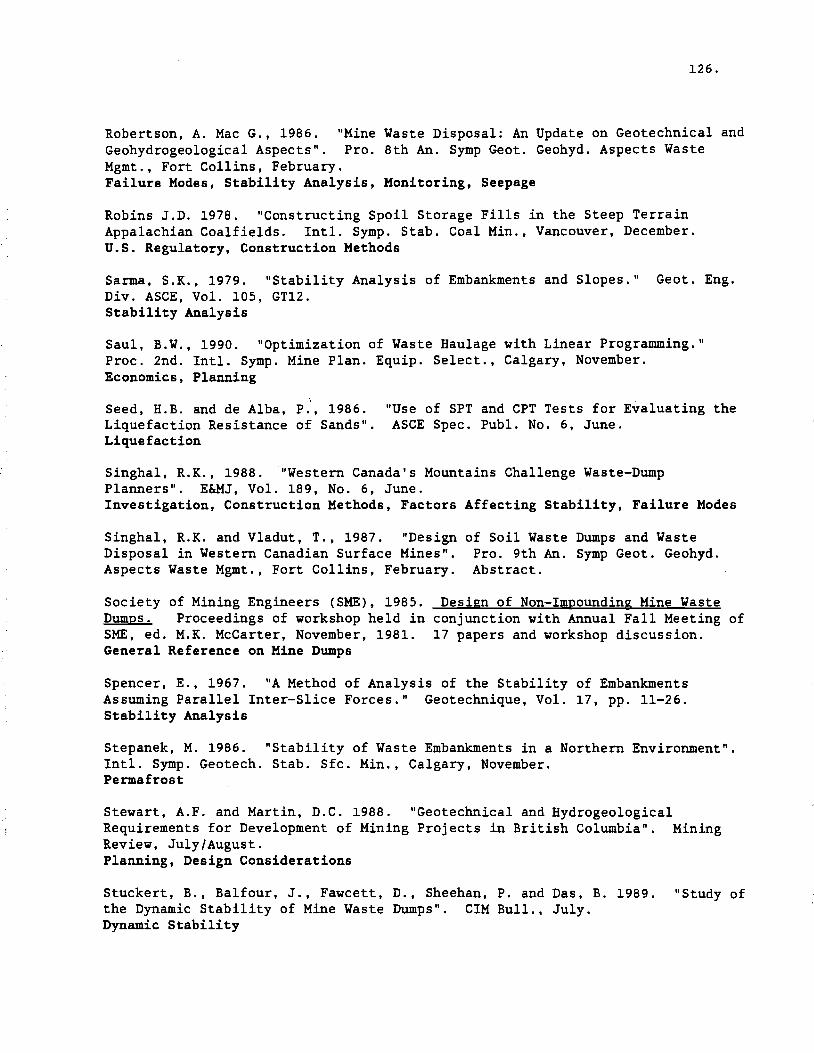
126.
Robertson, A. Mac G., 1986. "Mine Waste Disposal: An Update on Geotechnical and Geohydrogeological Aspects". Pro. 8th An. Symp Geot. Geohyd. Aspects Waste Mgmt., Fort Collins, February. Failure Modes, Stability Analysis, Monitoring, Seepage
Robins J.D. 1978. "Constructing Spoil Storage Fills in the Steep Terrain Appalachian Coalfields. IntI. Symp. Stab. Coal Min., Vancouver, December. U.S. Regulatory, Construction Methods
Sarma, S.K., 1979. "Stability Analysis of Embankments and Slopes." Geot. Eng. Div. ASCE, Vol. 105, GT12. Stability Analysis
Saul, B.W., 1990. "Optimization of Waste Haulage with Linear Programming." Proc. 2nd. IntI. Symp. Mine Plan. Equip. Select., Calgary, November. Economics, Planning
, Seed, H.B. and de Alba, P., 1986. "Use of SPT and CPT Tests for Evaluating the Liquefaction Resistance of Sands". ASCE Spec. Publ. No.6, June. Liquefaction
Singhal, R.K., 1988. "Western Canada's Mountains Challenge Waste-Dump Planners". E&MJ, Vol. 189, No.6, June. Investigation, Construction Methods, Factors Affecting Stability, Failure Modes
Singhal, R.K. and Vladut, T., 1987. "Design of Soil Waste Dumps and Waste Disposal in Western Canadian Surface Mines". Pro. 9th An. Symp Geot. Geohyd. Aspects Waste Mgmt., Fort Collins, February. Abstract.
Society of Mining Engineers (SME) , 1985. Design of Non-Impounding Mine Waste Dumps. Proceedings of workshop held in conjunction with Annual Fall Meeting of SME, ed. M.K. McCarter, November, 1981. 17 papers and workshop discussion. General Reference on Mine Dumps
Spencer, E., 1967. "A Method of Analysis of the Stability of Embankments Assuming Parallel Inter-Slice Forces." Geotechnique, Vol. 17, pp , 11-26. Stability Analysis
Stepanek, M. 1986. "Stability of Waste Embankments in a Northern Environment". IntI. Symp. Geotech. Stab. Sfc. Min., Calgary, November. Permafrost
Stewart, A.F. and Martin, D.C. 1988. "Geotechnical and Hydrogeological Requirements for Development of Mining Projects in British Columbia". Mining Review, July/August. Planning, Design Considerations
Stuckert, B., Balfour, J., Fawcett, D., Sheehan, P. and Das, B. 1989. "Study of the Dynamic Stability of Mine Waste Dumps". CIM Bull., July. Dynamic Stability

127.
Symons, G. ed.19B7. Flow Through Rock Drains - Proceedings of the International Symposium. 15 papers on design and performance of rock drains with particular reference to mine waste dumps. Cranbrook, September. Rock Drains, Laboratory Testing, Material Properties, Segregation
Tassie, W.P. 1987. "Waste Dump Management at Quintette Coal Limited". CIM Dist. 5 AGM, Ft. McMurray, Alta., September. Case History, Factors Affecting Stability, Monitoring, Failure Rehabilitation
Taylor, M.J. and Greenwood, R.J., 1981. "Classification and Surface Water Controls." Workshop on Design of Non-Impounding Mine Waste Dumps. SME. November. Classification, Hydrology
Terzaghi, K. and Peck, R.B., 1967. "Soil Mechanics in Engineering Practice." 2nd Ed. Wiley. General Reference on Soil Mechanics, Soil Properties
Thompson R.W. and Ferguson, D.A. 19B1. "The Impact of the Federal Surface Mining Control and Reclamation Act Upon Stability Designs for Surface Coal Mines". Proc. 3rd. Irrt l . Conf. Stab. Sfc. Min., Vancouver, June. u.S. Regulatory, Reclamation
U.S. Bureau of Mines (USBM), 1982. Development of Systematic Waste Disposal Plans for Metal and Nonmetal Mines. Minerals research contract report (Contract No. J0208033) for U.S. Dept. Int. Prepared by Goodson and Associates, Inc., 614pp., June. General Reference on Mine Dumps
Vandre, B.C., 1980. "Stability of Non-Impounding Mine Waste Embankments." USDA Forestry Service, Ogden, Utah. March. Stability Analysis, Stability Charts
Vandre, B.C., 1986. "Waste Disposal Design Standards: Putting Square Pegs in Round Holes?" Pro. 8th An. Symp Geot. Geohyd. Aspects Waste Mgmt., Fort Collins, February. u.S. Regulatory, Risk
Wagner, A.A., 1957. "The Use of the Unified Soil Classification System by the Bureau of Reclamation." Proc. 4th IntI. Conf. SMFE, London, Vol. 1. Butterworths. Soil Classification
Wahler, W.A., 1979. "A Perspective - Mine Waste Disposal Structures - Mine Dumps, and Mill and Plant Impoundments". Proc. 6th Panamerican Conf. Soil Mech. Fndn. Eng., Vol. III., Lima. Classification, Site Selection, Material Transportation
Weichert, D.H. and Rogers, G.C., 1987. "Seismic Risk in Western Canada." Symp. Earthquake Eng., Van. Geotech. Soc., Vancouver. May. Seismic Zoning

128.
Welsh, J.D., 1981. "Geotechnical Site Investigation". Workshop on Design of Non-Impounding Mine Waste Dumps. SME. November. Site Investigation
West, G., 1989. "Rock Abrasiveness Testing for Tunneling". Technical Note, Int. J. Rock Mech. Min. Sci. & Geomech. Abstr., Vo. 26, No.2. pp. 157-160. Durability
Zavodni, Z.M., Trexler, B.D. and Pi1z, J., 1981. "Foundation Investigation and Treatment". Workshop on Design of Non-Impounding Mine Waste Dumps". SME, November. Site Investigation, Stability

A·
BRITISH COLUMBIA WASTE DUMP SURVEY APPENDIX A
SECTION I
GENERAL INFORMATION AND CHARACTERISITICS OF WASTE MATERIALS
STATUS- Status of the waste dump on the date of the questionnaire response.
survey
DATE- Starting and finishing (anticipated if status dates of utilization of the waste dump.
is active)
MATERIAL- Primary geologic materials of which the waste composed and their approximate percentages.
dump is
Unconfined Compressive Strength of the waste Qualitative descriptions were used where quaninformation was unavailable.
matertitative
ials.
DURABILITY- LA=Los Angeles Abrasion test, SD = Slake Durability test. Qualitative descriptions were used where quantitative information was unavailable.
GRADATION- Percentages> 300 mm and < #200 sieve sizes. In some cases data for alternative sieve sizes have been provided.

WASTE DUMP
NO. AFT-1
NAME OF
MINE
Afton
OPERATOR
Afton Oper. Corporation .
LOCATION
10km W. of Kamloops
TYPE OF
MINE Open Pit Base Metal
WASTE DUMP NAME
#1 Main
STATUS
Finished
DATE Started Anlshed
77 8706
MATERIAL TYPE
DlorltelMagnetlteNolc Tertiary SedNolc/OB
% 75 25
UCS (MPa)
40-140 <10
DURABIlITY
15°Al V. Durablel 850Al V. Poor-Fair
GRADATION
°Al> %< 300mm #200
<15 <1
AFT-2 Ajax 5km S. of Kamloops
Open Pit Base Metal
South Active 9006 96
Diorite 100 40-120 Variable 30 <1
BAL-1 Balmer Westar Mining Ltd.
Sparwood Open Pit Coal
Baldy North 6200/61701 5990
Active 8903 Sandstone Mudstone Siltstone
65 25 10
100 30 55
High Low-Moderate
Moderate
75 40 50
2 15 10
BAL-2
BAL-3
BAL-4
BAL-5
A29E North + South
Erickson
AS1-4500
AS2-5167 to 4550
Active
Active
Finished
Projected
8903 9202
8106 9404
8906 9008
91 01 9806
Sandstone Siltstone Mudstone Sandstone Siltstone Mudstone Sandstone Siltstone Mudstone
73 24 2
48 33 19 60 26 14
BCC-1
BCC-2
Coal Mountain
Byron Creek Collieries
Corbin Open Pit Coal
East
West
Active
Active
88 Sandstone Siltstone Mudstone/shale
20-40 50
10-20
153-213 79-154 33-60
LA.. 25OAl/SD=99°Al lA.. 19%/SD=99°Al LA.. 15OAl/SD=980Al
70 50 30
0
<5 10
BEA-1 Beaverdell Tack Corporation
Beaverdell Undrgrnd Sliver
lass 4 Active 40's Granodiorite 100 High? High? 5 5
BEl-1 Bell Noranda
Minerals Inc.
Granlsle Open Pit
Base Metal
North Dump Active 79 Waste rock Overburden
98 2
20-150
BEl-2 South Dump Currently Inactive
72 89
Waste rock Overburden
95 5
BEl-3 NO.7 Dump Active 79 Waste rock Overburden
85 15
BEl-4 Overburden Dump
Currently
Inactive
70 82
Waste rock Overburden
40 60

WASTE DUMP
NO. BUL-1
BUL-2
NAME OF
MINE Bullmoose
OPERATOR
Bullmoose Operating Corporation
LOCATION
Tumbler Ridge
lYPE OF
MINE Open Pit Coal
WASTE DUMP NAME
West
Upper West
STATUS
Active
Active
DAlE .Started Anlshed
83 95
89
MATERIAL lYPE
Sandstone Mudstone
% 70 30
UCS (MPa)
125 60
DURABILITY
SD=97-98°At SD=83-97°At
GRADATION %> %<
300mm '200 50 2 10 2
BUL-3 East Flnlsheet 83 84
BUL-4 North Flnlsheet 83 89
\
BUL-5 In-Pit Active 83
CAS-1
CAS-2
END-1
END-2
Cassiar
McDame
Endako
Princeton Mining Corporation
Placer Dome
Cassiar
Endako
Open Pit Asbestos
Undrgrnd Asbestos Open Pit Moly.
Cirque
McDame
Burnsville
New
Flnlsheet
Active
Active
Planneet
89
mid 70's
91 94
Argillite Serpentinite
SerpentinIte Argillite Quartz Monzonite
60 40
80 20
100
50 35
35 50 110
Durable Suscep to lrzlthaw
High
50
20
30
10
10
2
EQS-1
EQS-2
EQS-3
FOR-1
FOR-2
Equity Silver
Fording
Equity Sliver Mines LId.
FordIng Coal LId.
Houston
26 km N of Elkford
Open Pit Sliver, copper. gold
Open Pit Coal
Main
Bessomer Ck
Southern Tall Blaine
Brownie
Flnlsheet
Active
Finished
FInIshed
Active
80 86 86 91 84 90
8302 8903
8302
Tuffaceous Volcanics GabbrolMonzonlte Quartz Lallte Dyke
Sandstone Siltstone Mudstone
90 10
25 50 25
50-112 90-115
130 110 55
Meetlum Low-Meetlum
High
LA.. 29°At/SD=99°At LA-34°At/SD=98°At
70 1
FOR-3 Clade Active 9002 93
FOR-4 South Spoil Stage 1
Active 8711
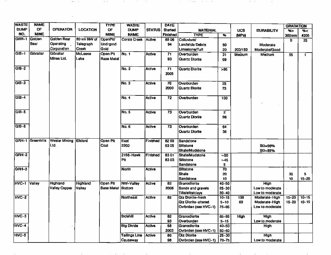
WASTE DUMP
NO. GBR-l
GIB-l
NAME OF
MINE Golden Bear
Gibraltar
OPERATOR
Golden Bear Operating Corporation Gibraltar Mines ltd.
lOCATION
80 km NWof Telegraph Creek Mcleese lake
lYPE OF
MINE OpenPIU Undrgrnd Gold Open Pit Base Metal
WASTE DUMP NAME
Corsls Creek
No.1
STATUS
Active
Active
DAlE Started Finished
8906 94
71 93
MATERIAL lYPE
Colluvluml landslide Debris UmestonefTulf Overburden Quartz Diorite
%
80 20 31 69
UCS (MPa)
200/150 Medium
DURABllnv
Moderate ModeratelGood
Medium
GRADATION %> %<
300mm '200 0 25
55 1
GIB-2 No.2 Active 71 2005
Quartz Diorite >95
GIB-3 NO.3 Active 76 2000
Overburden Quartz Diorite
25 75
G1B-4 No.4 Active 72 Overburden 100
GIB-5 No.5 Active 73 Overburden Quartz Diorite
2 98
GIB-6 NO.6 Active 73 Overburden Quartz Diorite
64 36
GRH-l
GRH-2
GRH-3
HVC-l
HVC-2
Greenhills
Valley
Westar MIning ltd.
Highland Valley Copper
Elk'ord
Highland Valley
Open Pit Coal
Open Pit Base Metal
East 2200
2158-Hawk Pit
North
NW-Valley Boltom
Northeast
Finished
Finished
Active
Active
Active
8209 8305
8301 8303
82 2006
82
Sandstone SlIIstone ShalefMudstone ShalefMudstone SlIIstone Sandstone Siltstone Shale Sandstone Granodiorite Sands and gravels Tills/slits/clays Otz Diorite-fresh Otz Diorite-altered Ovrbrden (see HVC-l)
"'50 ",45
5 70 20 10
40-50 25-30 30-40 10-15 5-10 75-85
138 69
SD-96DA! SD=85DA!
High low to moderate low to moderate Moderate-High Moderate-High low to moderate
30 10
15-20 15-20
5 15-20
10-15 10-15
HVC-3
HVC-4
HVC-5
Sldehlll
Big Divide
Tailings Une Causeway
Active
Active
Active
82 93 88
2003 86 98
Granodiorite Overburden Granodiorite Ovrbrden (see HVC-l) OIz Diorite Ovrbrden (see HVC-l)
85-95 5-15 40-50 50-60 25-30 70-75
High High low to moderate
High
High low to moderate

· .. 2 . . _._-_._~.-~- ._~ ~ ~--.- '-~-~._~'."---'--~---' -
WASTE DUMP
NO. HVC-6
NAME OF
MINE Bethlehem
OPERATOR
Highland Valley COPPQr
LOCATlON
Highland Valley
lYPE OF
MINE Open Pit Base Metal
WASTE DUMP NAME
Bethlehem
STATUS
Finished
DATE Started Anlshed
60 80
MATERIAL lYPE
Qtz Diorite % 100
UCS (MPa) High
DURABILITY
High
GRADATlON %> %<
300mm #200
HVC-7 Hlghmont
HVC-8 Lornex #2
HVC-9 HVC-l0
ICM-l Island Copper
ICM-2
BHP-Utah Mines Ltd.
Port Hardy Open Pit Base Metal
Hlghmont
Lornex N.E.
N.W.5065 N.W.4920
South
North
Dormant
Active
Finished
Finished
Finished
80 84 73
2002
73 97
8605 8705 7104 8508
Qtz Diorite Qtz Porphyry+some OB Otz Diorite Overburden Wei Overburden Granodiorite Overburden Andesite Porphyry Pyrophylllte Till
45-55 45-55 85-90 10-15 100
90-95 5-10
63 37
High
69-207 >103 <103
High
High Low Low High Low
Moderate Moderate
Low
20 2
tCM-3
ICM-4
ICM-5
West
West In-pit
Beach
Finished
Acllve
Active
8603 8609 8910 9209 7108 9512
Rock Till
85 15
LCR-l
LCR-2
Line Creek Crowsnest Resources Ltd.
Sparwood Open Pit Coal
Mine Service
Area West Line Creek
Finished
Active
86
88 8107
91
Sandstone Shale Siltstone Overburden
30-60 25-50 40-60
<5
150 25-50
100 SD~93-98%
60 40 25
0 5 10
LCR-3 Upper West Line Creek
Active 87
LCR-4 Line Creek Valley
Acllve 9009 92
LCR-5 No Name Creek
Finished 86 87

WASTE DUMP
NO. MYR-1
MYR-2
NAME OF
MINE LynxlHW
OPERATOR
Westmln Resources ltd.
LOCATION
Myra Falls
TYPE OF
MINE Open PIU Undrgrnd Base Melal
WASTE DUMP NAME
No.1
No.2
STArnS
Active
Finished
DATE Started Anlshed
66 98
67 72
MATERIAL TYPE
Altered Rhyolite Andesite Massive Pyrite
% 50 50 <5
UCS (MPa)
Low-med. High
DURABILITY
Poor High
GRADATION %> %<
300mm #200 1 1
10 10
NPL-1 Nickel Plate
Corona Corp. Hedley Open Pit Gold
North Active 8803 Skarn Andesite
70 30
69-413 High 75 5
PRE-1
PRE-2
Premier Gold
Westmln Mines Stewart Ltd.
Open Pit Gold
650/585 South
685/665 Upper North
Active
Finished
8909 9012
8805 9008
Andesite extrusive flows and tulls Porphyritic andesite
50
50
22-38
69-94
Moderate
Moderate
25> 25< 1000mm 20mm
PRE-3
PRE-4
615/535 Cooper Creek 585 Wilson Creek
Active
Active
88
8908
aCL-1
aCL-2
aCL-3
Mesa auintette Coal ltd.
Tumbler Ridge
Open Pit Coal
1570 Phase 2
1506 Phase 1
1545 Mesa Early
Active
Active
Active
8710 9205
9008 9106
8803
Sandstone/ Conglomerate Siltstone
Mudstone/Carb. MdsU Coal
50
20
30
>103
83
7-:34
High - V. High
Medium - High
V. Low - Low
75> 100mm
60> 100mm
40> 100mm
5
15
20
aCL-4 Wolverine 1660 North
Active 82 9101
aCL-5
aCL-6 Shlkano
1595 South North
Active
Active
9008 9011 8611 2000
aCL-7 Lower South Currently Inactive
8609
aCL-8 770 Haul Road
Active 9106

WASTE DUMP
NO. QSM-1
NAME OF
MINE Qulnsam
OPERATOR
BrlncoCoal
.
LOCAll0N
Campbell River
lYPE OF
MINE Open Pit Coal
WASTE DUMP NAME
No.1
STA1\JS
Anlshed
DATE Started
FInished 8909 9010
MATERIAL lYPE
Siltstone/Sandstone Till
% 70-BO 20-30
UCS (MPa)
DURABILITY
Poor-slakes easily
GRADATION %> %<
300mm #200 70 <2 10 <35
aSM-2 No.2 Finished B908 9007
QSM-3 No.3 Active BB 08 9105
SAM-1 Samatosum Mlnnova Inc. Barriere Open Pit Sliver
Main A and B
Active 8903 92
Mafic Pyroclastics Sericite
63 25
30-70 12-16
LA..320Al/SO..96°Al Poor
0 0
SIM-1
SIM-2
Simllco Mines ltd.
Prlncelon Mining Corporation
Princeton Open Pit Base Metal
02
03
Inactive
Finished
83 89
83 89
Andesite Diorite Felsite Dykes
65 25 10
High
High
SUL-1
SUL-2
Sullivan Mine
Comlnco Ltd. Kimberley OpenPIU UlG Base Metal
#1 Shaft
Open Pit
Active
Finished
46 92
51 60
Argillite Quartzite
175 High Bulk< 150mm
SUL-3 3900 Finished BO's

BRITISH COLUMBIA WASTE DUMP SURVEY APPENDIX A
SECTION II
DUMP CONFIGURATION
TYPE OF DUMP-Describes i}the general classification category of nonimpounding structures e.g. a}Valley Fill, b}Cross Valley, c}Sidehill, d}Ridge Crest and e}Heaped; and ii}the configuration of the overall slope e.g. benched, unbenched, resloped, etc.
STAGE OR PHASE-Indicates whether the following infor.mation is for the current,the ultimately proposed or already completed dump.
VOLUME- Volume of waste dump in Bank Cubic Meters (BCM' s). Where dump masses were not provided by the mining company it was assumed that the volume units were in BCM. Where only the dump mass was provided, BCM's were calculated assuming a specific gravity of 2.6 for the waste. Where volumes were provided in bulk cubic meters, these were reduced to BCM's using a bulking factor of 1.25.
OVERALL SLOPE-See diagram (on following page).
MAXIMUM HEIGHT-See diagram.
MAXIMUM THICKNESS-See diagram.
BERM WIDTH- See diagram
MAXIMUM WIDTH-See diagram.
LIFT THICKNESS-Maximum thickness of lift placed during construction.
MAXIMUM BENCH HEIGHT-Maximum height between any two consecutive ber.ms on the waste dump slope. In some instances the maxiumum bench height was determined by dividing the maximum height of the dump by the number of benches and therefore the value presented may be a lower bound. Queried where uncertain.
NUMBER OF BENCHES-Number of rises in the bench slope between the toe of the slope, and the dump platform. In some instances this value was interpreted from other infor.mation provided, and is queried where uncertain.
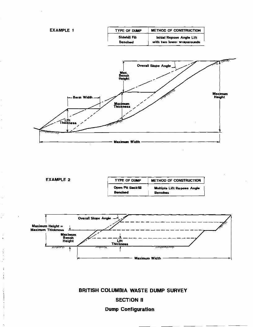
EXAMPLE 1 TYPE OF DUMP METHOD OF CONSTRUCTION
Sidehill Fill Initial Repose Angle Lift Benched with two lower wraparounds
1 Max..
Bench Height
Maximum Height
.---------------- Maximum Width ---------------.
EXAMPLE 2 TYPE OF DUMP METHOD OF CONSTRUCTION
Open Pit Backffll Multiple Lift Repose Angle Benched Benches
y. ,
Maximum Height = C Maximum Thickness ..:f --:......-.'?"-_
M~~~ _~ 1 _ Height Lift
Thickness
+----------- Maximum Width --------------1
BRITISH COLUMBIA WASTE DUMP SURVEY
SECTION II
Dump Configuration

WASTE DUMP
NO.
TYPE OF
DUMP
STAGE OR
PHASE
VOLUME (BCM's xl0E6)
OVERAll SLOPE
(0)
MAXIMUM HEIGHT
(m)
MAXIMUM THICKNES~
(m)
MAXIMUM WIDTH
(m)
CREST lENGTH
(m)
PLAN AREA (ha)
SHAPE IN
PLAN
LIFT THICKNESS
(m)
UAXBENCH
HEIGHT
(m)
NUMBER OF
BENCHES
BERM WIDTH
(m) AFT-l Valley Fill
Benched Ultimate 121 22 90 90 490 1370 100 Arcuate-
lobed 15 15 6 21
AFT-2 Sldehlll Fill Benched
Ultimate 11.5 19-24.5 90 86 600 1700 47 Arcuate 3 15 6 20
BAl-l Open Pit Backfill Ultimately Benched
Current Ultimate
5 28
37 15 91 100 50
90 275
20 linear 100 43
1 4
N/A 100
BAl-2 Sldehlll Fill Ultimately Benched
Current Ultimate
28 41
37 20? 312 100 122 250 100 Convex 100 15?
South-5 North-l0 45?
BAl-3 Sldehlll Fill Unbenched
Current Ultimate
140 210
37 37
274 244 250 610 915 1114 linear 250 244 1 N/A
BAL-4 Sldehlll Fill Unbenched
Ultimate 1 37 46 37 122 244 11 Convex 37 46 1 N/A
BAl-5 Sldehlll Fill Ultimately Benched
Ultimate 25 21 265 100 335 100 65 Convex 100 53+ 5
BCC-l Valley Fill Benched
Current Ultimate
3 20 20?
75 75 600 <600 100 Linear 40 40
40+ 40+?
2 6
BCC-2 Sldehlll Fill Benched
Current Ultimate 25
37 26
200 250
50 100
700 700
linear 60-70 60-70
200? 60-70
1? 3-4
N/A
BEA-l Sldehlll Fill Unbenched
Current Ultimate
0.0085 0.014
45 46 52
21 linear 21 46 52
1 1
N/A N/A
BEL-l Sldehlll Fill Benched
Current Ultimate
6.3 30.8
25 25
40 60
35 50
500 100
400 750
50 150
Convex 10-15 10-15
20? 30?
2? 2-3?
BEl-2 Sldehlll Fill Benched
Current Ultimate
2.8 4.4
20 20
30? 30?
50 50
600 600
550 550
30 40
Linear 25 25
30? 30?
2? 2?
BEL-3 SldehlllNalley Fill Benched
Current Ultimate
4.1 8.1
15 20
42? 45?
35 45
600 600
.850 900
40 40
Linear 25 30
14? 15?
3? 3?
BEl-4 Sldehlll Fill Benched?
Current Ultimate
4 6.8
31 31
40 40
45 45
400 600
1050 1050
20 25
Convex 12 12
14? 14?
3? 3?

WASTE DUMP
NO.
TYPE OF
DUMP
STAGE OR
PHASE
VOLUME (BCM's xl0E6)
OVERALL SLOPE
(0)
MAXIMUM HEIGHT
(m)
MAXIMUM THICKNESS
(m)
MAXIMUM WIDTH
(m)
CREST LENGTH
(m)
PLAN AREA (ha)
SHAPE IN
PLAN
LIFT THICKNESS
(m)
UAXBENCH
HEIOHT
1m)
NUMBER OF
BENCHES
BERM WIDTH
(m) BUL-l Sldehlll Fill
Benched Current Ultimate
20 27
28 28
230 280
110 200
400 400
200 200 79
LInear 50 50
501 501
51 61
30 30
BUL-2 Sldehlll Fill Ultimately Benched
Current Ultimate
0.85 20
36 28
100 300
40 100
150 300
300 400 34
Linear 50 50
501 501
21 61
30 30
BUL-3 Sldehlll Fill Benched
Ultimate 2 27 80 50 100 400 2.0 Linear 50 501 21 30 <
BUL-4 Sldehlll Fill Unbenched1
Ultimate 7 36 50 50 200 700 2.1 LInear 50 501 11 N/A1
BUL-5 Sidehill Fill Benched
Current Ultimate
40 125
28 28
150 350
140 140
1000 1000
1000 1000
187 Linear 50 50
501 501
31 71
30 30
CAS-l SldehlllNalley Fill Benched
UlIlmate 30 15 360 40 350 350 50 Convex 4
CAS-2 Sldehlll Fill Unbenched
Current 55 38 30 20 300 2 Convex 20 30 1 N/A
END-l Sldehlli Fill Benched
Current 37 251 251 90 60 2.2 Linear 12 131 2
END-2 Ultimate 22 37 34 34 305 305 16 Linear 15 171 2
EQS-l Sldehlll Fill Benched
Ultimate 33 20 90 55 550 1000 52 Convex 10 10 9 10
EQS-2 Sldehlll Fill Benched
Ultimate 6.3 20 40 40 300 1000 27 Convex 10 10 4 10
EQS-3 Open Pit Backfill Resloped
Ultimate 8 14 50 501 300 1000 30 Convex 10 10 5 10
FOR-1 Sldehlll Fill Ultimately Benched
Current Ultimate
20 100
37 32
185 295
126 170
250 430
900 1600
23 131 Convex
126 170
185 295
1 1
N/A N/A
FOR-2 Sfdehlll Fill Ultimately Benched
Current Ultimate
80 463
37 32
3601 2401
130 285
250 1600
1400 2000
13.3 400 Linear
130 285
360 240
1 1
N/A N/A
FOR-3 Sidehlll Fill Unbenched
Current Ultimate
19.6 18.6??
37 37
120 140
100 140
60 600
100 1440
1.2 9.6 Triangular
100 140
120 140
1 1
N/A N/A
FOR-4 Sldehlll Fill Ultimately Benched
Current Ultimate
14.9 14.9
35 32
413 435
142 125
180 1401
475 4501
13.1 24 Convex!
Linear
142 125
413 435
1 1
N/A N/A

WASTE DUMP
NO.
TYPE OF
DUMP
STAGE OR
PHASE
VOLUME (BCM's x10E6)
OVERALL SLOPE
(0)
MAXIMUM HEIGHT
(m)
MAXIMUM IrHICKNESS
(m)
MAXIMUM WIDTH
(m)
CREST LENGTH
(m)
PLAN AREA (ha)
SHAPE IN
PLAN
LIFT THICKNESS
(m)
MAX BENCH
HEIGHT
(m)
NUMBER OF
BENCHES
BERM WIDTH
(m) GBR-1 Sldehlll Fill
Ultimately Benched Current Ultimate
0.4 1.0
38 35
150 .250
50 50
20 20
210 210
4.0 6.5
Linear 50 50
150 125+?
1 2?
N/A N/A
GIB-1 Sldehlll Fill Benched
Current Ultimate
12 17
26? 171
76 79
70 70
305 305
1524 1768
42 45
Arcuate 24 25 26
3 3
30 30
GIB-2 Heaped Fill Benched
Current Ultimate
0.7 0.9
17.5? 16?
32 43
24 31
213 244
732 793
7.8 8.4
Linear 11 11
11 11
3 4
30 30
GIB-3 Sldehlll Fill Benched
Current Ultimate
22 23
6 6
73 73
72 72
488 488
2012 2012
28 28
Arcuate 12 12
12 12
6 6
120 120
GIB-4 Sldehlll Fill Benched
Current Ultimate
31 53
14 15
131 171
70 104
1067 1067
1524 1829
111 130
Arcuate 15 15
26+? 34+?
5 5
120 120
GIB-5 Sldehlll Fill Ultimately Buttressed
tst Lift Ultimate
19 24
37 30
110 110
87 87
457 457
610 1219
45 63
Arcuate 87 15
110 80?
1 3
N/A 60
GIB-6 Sldehlll Fill Benched
Current Ultimate
7 31
30 30
70 107
31 46
244 610
1829 2256
34 98
L1nearl Arcuate
18 15
35+? 25+?
2 4
60 60
GRH-1 Sidehill Fill Benched
Ultimate 4 33 168 80 110 400 30 Linear 118? 3
GRH-2 Sldehlll Fill Unbenched
Ultimate .7 38 160 35 450 300 27 Fan 35 160 1 N/A
GRH-3 SldehlllNalley Fill Benched
Current Ultimate
60 100
26 26
363 400
100 100
500 500
200-400 50 85
Linear 200? 200?
325? 3
HVC-1 Valley Fill Benched
Current Ultimate
371 15 90
15 90 ",1000
Linear 2.5 2.5
15 15+?
1 6?
N/A
HVC-2 Sldehlll Fill Benched
Current Varies 90 90 Varies Varies Varies Varies
HVC-3 10-25
HVC-4 5-10
HVC-5 ",20

' ..... . - --- ·.' .' ..~~~.-~~- .." --- ._-----.
\
WASTE DUMP
NO. HVC-6
TYPE OF
DUMP
STAGE OR
PHASE
VOLUME (BCM's x10E6)
OVERALL SLOPE
(0)
MAXIMUM MAXIMUM MAXIMUM HEIGHT rrnICKNE~ WIDTH
(m) (m) (m) 100-200
CREST LENGTH
(m)
PLAN AREA (ha)
SHAPE IN
PLAN
LIFT THICKNESS
(m)
MAXBENCH
H801fT
(m)
NUMBER OF
BENCHES
BERM WIDTH
(m)
HVC-7 70
HVC-8 90
HVC-9 HVC-10
90 120
ICM-1 Sldehlll Fill Unbenched
ICM-2 Sldehlll Fill . Benched
Ultimately Resloped ICM-3 Heaped Fill
Unbenched/Resioped7 ICM-4 Open Pit Backllll
Benched ICM-5 Marlne-Sldehlll Fill
Unbenched
Ultimate
Ultimate
Ultimate
Ultimate
Current Ultimate
3.8
38.9
2.1
6.8
242 282
37
30
30
37
35 35
56
47
20
152
91 91
56
47
20
152
707 707
335
610
201
244
1067 1097
853
4877
884
244
4145 5029
15
141
14.2
6.9
247 328
Rectangular
Linear
Oblong
Inverted Cone
Rectangular
56
12
20
6
70 70
56
12
20
76+7
91 91
1
4
1
27
1 1
N/A
N/A
30
N/A N/A
LCR-1 Sldehll' Fill Unbenched
Ultimate 1 37 60 60 50-100 1000 10 Linear 30-60 30-60 1-2
LCR-2 SldehlllNalley Fill Ultimately Benched
Current Ultimate
90 100
37 240 160 400 2100 125 200
160 240 100
1 137
N/A 50
LCR-3 Current Ultimate
5-10 37 150 80 40 150 2 80 150 1 57
N/A 50
LCR-4 tst Lift Ultimate
1 50
37 28
175 155 35 250
250 500
2 95
155 175 50?
1 4?
N/A 50?
LCR-5 Sldehlll/Cross Valley Benched?
Ultimate 10 26 100 60 30 200 15 Linear <60

WASTE DUMP
NO. MYR-1
TYPE OF
DUMP Sldehlll Fill Unbenched
STAGE OR
PHASE Current Ultimate
VOLUME! OVERALL MAXIMUM MAXIMUM MAXIMUM (BCM's SLOPE HEIGHT ~HICKNES~ WIDTH x10E6) (0) (m) (m) (m)
.54 43? 50 30 500
.85
CREST LENGTH
(m) 500
PLAN AREA (ha)
SHAPE IN
PLAN linear
LIFT THICKNESS
(m) 20
MAX8ENCH
HEIOKT
(m)
50
NUMBER OF
BENCHES 1
BERM WIDTH
(m) N/A
MYR-2 Sldehlll Fill Benched?
Ultimate .69 42? 180 30 300 130 5 Linear 20 90? 2+?
NPL-1 Sidehill Fill Unbenched
Current 2.4 37 98 46 1200 1300 8.8 Triangular 30 98? 1?
PRE-1 Sidehlll Fill Unbenched
1st lift Ultimate
1.5 1.8
37 37
30 65
30 65
40 40
200 300
linear 30 30-65
30 65
1 1
N/A N/A
PRE-2 Sidehill Fill Benched
Ultimate 1.5 20-35 70 70 40 1000 linearl Arcuate
20-50 20-50 2-3 0-30
PRE-3 Sldehlll Fill Unbenched
Current Ultimate
.31 1.9
37 37
100 130
50 130
50 50
400 400
Convex 30-100 30-130
100 130
1 1
N/A N/A
PRE-4 Sldehlll Fill Unbenched
1st lift Ultimate
.8 1.5
37 35
20 125
20 55
75 75
600 825
2.3 3.1
Concave 20 20-125
20 125
1 1
N/A N/A
aCL-1 Sidehill Fill Ultimately Benched
Current Ultimate
"'10 ",22
37 <26
250 265
120 170
110 120
250 250 90
Convex 30 30
250 100
1 5
N/A
aCL-2 Cross Valley FIII?/Road Unbenched
Current Ultimate
37 37
140 140
25 110
100 100
40 200
4 20
Linear 25 110
140 140
1 1
N/A N/A
aCL-3 Sldehlll Fill Ultimately Benched
Current Ultimate 5
37 <26
180 180
80 80
100 150
250 300
18 28
Convex 80 80
180 100
1 2
N/A 100
aCL-4 SidehlllNalley Fill Ultimately Benched
Current Ultimate
15 23
37
<26
250 250
150 150
200 200
500 500
36 56
Convex 130 130
250 90
1 2
N/A 50
aCL-5
aCL-6
Road Ultimately Benched Sidehlll Fill?
Benched
Current Ultimate Current
Ultimate
.92
.98 30 80
37 <26 26 26
120 120 106
260
70 70 60
190
45 45 60
190
40 40
500 300
4.5 6.8 16.5 16.5
linear
Convex
70 70 20 20
120 20 22 22
1 3 3
10
N/A 40
aCL-7 Heaped Fill Benched
Current Ultimate
3.7 14 45 40 500 1100 330
Convex 15 22 3
aCL-8 Road Unbenched
Current Ultimate
.14
.26 37 37
40 40
30 30
40
40
40 1750
20 70
linear 40 40
1 1
N/A N/A

BRITISH COLUMBIA WASTE DUMP SURVEY APPENDIX A
SECTION III
FOUNDATION CONDITIONS AND DESIGN
PHYSIOGRAPHY-Description of foundation configuration and geometry in section and in plan. Perennial drainage is also noted.
SLOPE (ANGLE)-Angle of underlying foundation slope i) in the toe region of the dump, ii)the range of angles observed, and iii)the average slope beneath the dump. Negative angles indicate the foundation slopes in the opposite direction to the dump face.
FOUNDATION MATERIALS AND CONDITIONS-Description of geologic materials encountered or assumed/expected to be at the base of the waste dump. Seepages and springs are also noted.
SHEAR STRENGTH-Parameters used to define the strength of the foundation and waste "materials for input to the stability analyses performed. 0 = friction angle and Su= undrained strength.
FACTOR OF SAFETY-Calculated by the indicated analysis technique under either static or seismic conditions. N/D = analysis not done, NIS = analysis performed but results not specified.

WASTE lYPE STAGE VOLUME OVERALL MAXIMUM MAXIMUM MAXIMUM CREST PLAN SHAPE LIFT MAX BENCH NUMBER BERM DUMP OF OR (BCM's SLOPE HEIGHT THICKNESS WIDTH LENGTH AREA IN THICKNESS HEIGHT OF WIDTH
NO. DUMP PHASE x10E6) (0) (m) (m) (m) (m) (ha) PLAN (m) (m) BENCHES (m) QSM-1 Heaped Fill Current .4 38 20 20 80 ·230 3 Convex 2 20 1 N/A
Ultimately Benched? Ultimate .4 27 20 20 80 230 3 2
QSM-2 Heaped Fill Benched
Ultimate 1 27 30 30 100 200 5.3 Convex 2 2? 15?
QSM-3 Sidehlll Fill Current 1.5 38 20 20 120 550 9.1 Convex 2 1 N/A Ultimately Benched Ultimate 2.3 27 20 20 120 550 9.1 2
SAM-1 Sidehlll Fill Current 2.7 37 75 70 350 250 22 Convex 6 75? 1? N/A Ultimately Benched Ultimate 3.3 27 75 60 350 250 25 6 15+? 5?
SIM-1 Sidehlll/Heaped Fill Current 5 32 101 52 457 351 26 Convex 31 50? 2 15 (min) Benched Ultimate 32 119 73 31 40-50+? 3 15 (min)
SIM-2 Sldehlll Fill Benched
Ultimate 15 27 181 70 518 1646 67 linear 31 36+ 5 15 (min)
SUl-1 Sidehlll Fill 1stlltl 0.7 37 30 30 244 549 13 Concave 30 30 1 N/A Benched Ultimate 0.9 27 30 30 280 549 15 30 14+ 2 8
(resloped)
SUl-2 Sldehlll Fill Unbenched
Ultimate 0.9 35 40 40 213 914 11 Concave 40 40 1 N/A
SUl-3 Valley Fill Ultimate 19.5 linear

WASTE SLOPE FOUNDATION
INVESflllATIONDUMP SITE PHYSIOGRAPHY TOE RANGE AVG
NO. (0) (0) (0)
BUl-1 Moderalely steep sldehlll. 10 Test pits concave In plan and section. to Drillholes
15 BUl-2 Moderalely steep sldehili. 15 15 Test pits
convex In plan, concave In to Drillholes section. 45
8Ul-3 Moderate to steep sidehlll. 30 6 Test pits convex In section. to to Drillholes
40 40 BUl-4 Moderately sloping sldehill, 10 5 Test pits
linear In plan and convex In to to Trench section. 20 35 Drillholes
BUl-5 Footwall of coal,concave in plan 10 Test pits convex In section. to Drillholes
15
CAS-1 Sldehlll progressing downslope Into a V-shaped valley.
CAS-2 Moderately steep sldehlll. Seismic refraction
END-1 Relatively flat. Exploration drilling
END-2 Relatively flat. 2 Exploration drilling
EQS-1 Gentle sidehlll. 10 2to 13
5 Drillholes
EQS-2 Gentle sldehill, convex In plan. ~ Oto 5
3
EQS-3 Mined-out pit
FOR-1 Concave, U-shaped sidehills, 16 16 27 29 test pits linear In plan. to 3 Becker
40 FOR-2 Mod. to steep concave sldehllls, 10 10 33 test pits
Irreg.lllnear In plan. to 60
FOR-3 Existing pit excavation. Visual recon.
FOR-4 Mod. steep sidehll/, concave In 23 31 28 8 test pits plan and section. Expands to 5 Becker Into Kilmarnock valley floor. 33 18 Rotary
FOUNDATION MATERIALS AND CONDIllONS
Blanket (>2m) colluvium/IIII overlies massive sandstone.
Veneer (0.3m) glacial till overlies interbedded sandstone/mudstone.
Veneer colluvlun overlies bedrock. Toe underlain by glacial till.
Veneer colluvium overlies bedrock. II 38°,ij Pl 63°At
Sandstone. Thrust fault dips into slope. Plastic clay layer observed in one drlllhole.
Glacial till.
Swampy.
Silly sand and gravel, trace clay.
0- 30m till.
5 - 30m till.
Bedrock.
Veneer of colluvium overlies dense tills. local weak zones of sal'd surficial clays. Occasionally disturbed. low to medium plastlclly fines. Colluvial solis consisting of reworked Kootenay-Fernie Formation.
Mined out footwalls and hlghwalls.
Veneer of colluvium along sldeslope with till bench at toe and alluvium below till bench.
DESIGNED SHEAR STRENGTH STABILITY
IINAlYSIS
METHOD
MIN.
F.O.S.
STATIC
MIN.
F.O.S.
SEISMIC
WASTE
" (0)
FOUNDAnON
" (0)BY DATE Klohn leonoff
8302 Ssd:42 MUd:3
0/B:36 B/R:42
Morgnslr Price
1.3 N/S
In-house
In-house 9010 36° c=
490kPa
30° c=
290kPa
Horiz. Transltn.
1.33 1.25
Klohn leonoff
8402 37.5 25 1.3 1.1
Golder 8202 8210
27 (22-25)
Basal Sliding
'" 1.0 NID
Golder 8303 37 37-40 Double Wedge
1.53 N/D
Golder 9001 37 Double Wedge
'" 1.0 N/D
Golder 8704 37 Colluv.=38 TII/=32
Double Wedge
1.20

WASTE SLOPE FOUND...T1ON SHEAR smENClTH srABn.JTY IIIN. IIIN.
DUMP SITE PHYSIOGRAPHY TOE RANGE "'YO INVESTI(),\T1ON FOUNDATION MATERIALS AND CONDmONS DESIGNED WASTE FOUND...TION I'NAlYSIS F.O.S. F.O.S.
NO. (0) (0) (0) BY DATE III(0) III(0) IIETHOD sr...TIC~SMI(
AFT-1 Glaciated, rounded ridges and <5 Bedrock or veneerlblanket overconsol. dense glacial In-house swales (NW-SE drumlins). till overlies bedrock. Slit lenses associated with
local glacial depressions.
AFT-2 Moderate 10 lIat sldehlll, rounded 0 0 4 5 test pus Veneer overconsol. dense glacial drift overlies bedrock. In-house 9006 36 Till: 36 Bishop 1.85 1.4 ridge and swale, drumllnold. . 10 3m loose-mod. dense outwash sand/slit/gravel with high (Rev. by Alluv:32 Slmpllld.
24 waler tabla underlies loe. Silly deposits assoc. wllh Klohn SIII:22 local glacial depressions underlie small portion of crest. leonof!)
BAl-1 Mined-out pi\. Dump founded -10 -10 Sedimentary bedrock, bedding dips Into the slope. Golder 8811 38 36 Double 2.3 NID on benched hanging wall, with to Wedge toe bullressed by opposite 54 dIpping foolwall. i
BAl-2 Steep sldehlll, Irreg. In plan, 0 0 25 Colluvium. 8908 38 32 Double 1.0 N/D concave In section. to Wedge
47
BAl-3 Steep sldehlll, Irreg. In plan, 0 0 21 15 test pits Gravelly sand with some slit (Colluvium) and coal bloom 8108 37 33-39 Sarma 1.1 N/D concave In section. Crossed by to underlies slope. Sand and gravel oulwash and line sand Erickson Creek. 40 and sill alluvium underly lower slopes/valley bottom.
BAl-4 Relallvely gentle slope. 11 11 15 Sandy sill (weathered 1111) overlying very dense well 8409 38 40 Bishop 1.25 N/D to graded glacial 1111 overlying Crelaceous sedimentary 18 units dipping 35°-45°.
BAl-5 Relatively gentle slope 10 10 14 4 test plls 9003 38 40 Bishop & 1.1 N/D to 13 drlllhole~ Morg.-23 Price
BCC-1 V-shaped Corbin Ck valley. 22 test pits Till, colluvium and alluvium. Plteau 8403 37 Till: 35 Janbu 1.17 Irreg., concave slopes. 7 drillholes Alluv:32
BCC-2 Moderately steep sldehili. 16 20 22 Till and alluvium, soft, saturated. EBA 87/88 to 30
BEA-1 Dry gully on sldehlll. 25 thin veneer soli overlies bedrock. N/D to 30
BEl-1 Gentle sldehlll, 500.41 of toe but- -4 -4 3 Till. 2 shallow sloughs In valley saddle. NID tressed by opposUe valley slope. 10
7· BEl-2 Gentle sldehlll, 800.41 of dump 1 0 1 Till and lacustrine deposits.
on levellerraln. 10 -2
BEl-3 Predominantly mod. sloping 6 0 10 Till.
sldehlll, concave In section. to Partly toed Inlo rock ridge 15
BEl-4 80% mod. to gently sloping 6 0 7 Till.
sldehili. 20% flat, partly to
toed Into rock ridge. 10

WASTE SLOPE FOUNDATION
INVESTIGATION FOUNDATION MATERIALS AND CONDmONS DESIGNED SHEAf
WASTE
III (0)
STRENGTH
FOUNDATION
III (0)
STABILITY
ANAlYSIS
METllOD
MIN.
EO.S.
STATIC
MIN.
F.O.S.
SEISMIC
DUMP SITE PHYSIOGRAPHY TOE RANGE AVa
NO. (0) (0) (0) BY DATE aSM-1 Level terrain with hardpan
approx 10m thick. 0 0 4 drillholes
2 lest pits Dense, well cemented Impervious clay till.
aSM-2 Level terrain. 0 0 N/D Hard, cemented till.
aSM-3 Mod. steep sldehlll steepened by 36 0 10 Drillholes subcrop mining of coal seam. to Testplls Convex In plan and In section. 36
SAM-1 Mod. steep sldehlll, concave In 22 10 15 9 test pits Glaclallill and colluvium <5m thick. Seepage points Piteau plan, Irregular In seclion. to over full long section of dump. Intermillent springs. 25
SIM-1 Flat to mod. steep, convex In 10 5 9 test pits Outwash material and glaciallill, competent volcanic Golder 37 37 Janbu plan and In section. to bedrock. 2 Wedge
10 Sarma N/S SIM-2 Mod. steep sidehlll, irregular 25 10 18 10 test pits Silty sandy gravels with trace of clay. Compact to very Golder 37 37 Janbu
In plan, convex In seclion. to dense. 2 Wedge 25 Sarma N/S
SUL-1 Gently sloping sldehlll, sllghliy 4 4 6 24 test pits Clay, sand with frequent pebbles and cobbles. convex In plan. to Argillite/quartzite bedrock. No seepage In test pits.
10 SUL-2 Gently sloping sldehlll, concave 3 0 3 Weathered argillite/quartzite bedrock with some
In plan, smooth In section. to shallow, Isolated gravel and clay pockets. 5
SUL-3 V-shaped Mark Creek Valley.

WASTE SLOPE FOUNDATION SHEAF STRENOTH STABILITY MIN. MIN.
DUMP NO.
SITE PHYSIOGRAPHY TOE
e) RANGE
(0) AVO
(0) INVESTIGATlON FOUNDATION MATERIALS AND CONDITIONS DESIGNED
BY DATE WASTE
" (0)
FOUNDATION
" (0)
ANAlYSIS
METHOD
F.O.S. F.O.S.
STATIC SEISMIC
MYR-1 Mod. steep sldehlll, Irreg. In 10 10 30 NID Glacial till (assumed) and top soil. NID plan and section. to
35 MYR-2 Mod. steep sldehlll, Irreg. In NID Glacial till and rock. NID
plan and section. Some seepage.
NPl-1 Mod. steep sldehill bollomlng 12 10 25 Colluvial deposils and minor glacial till, both with high Hardy BS 86 Into steep V-Shaped valley. to percentage of rock fragments. linear In plan, Irreg. In section. 31
PRE-1 Mod. steep to steep sldehlll, 0 0, 25 Recon. Clayey glacial tills and gravels. Plteau 8804 convex In plan, Irreg. In section. to Test pits No perched groundwater tables. Crossed by small V-shaped ck. 30 Exploration
PRE-2 Gentle to steep sldehlll, convex 0 20 drillholes Glacialtlllslclays, some local pockets of organic to concave In plan and Irreg. In to soils, up to 2m thick. 25-30°,i) bedrock. section. 30
PRE-3 Mod. to v. steep sldehlll, cone. 0 0 25 Glacial tlllslclay, gravel and bedrock (200,i). Smooth In-House 8B189 In plan, uniform In section. to to bedrock surface underlies thin till layer. Crossed by Cooper Creek. 15 35
PRE-4 Steep sldehlll, linear In plan 10 -10 30 Predominantly bedrock (60°,i) and glacial till (40°,i). Golder 89 Su= Su= Janbu 1.0 NID and benched In section. to to 1378 50 Crossed by Wilson Creek. -10 50 kPa. kPa.
oct-i Moderately steep sldehill, 10 10 7 test pits Thin veneer granular or organic soils overlies Golder 88 37 33 2 Wedge "'1.2 convex in plan, concave In to 6 Berma weathered bedrock. Janbu section. 40 probes simplifd.
oct-a Steep sldehill and V-shaped 19 0 20 Alrphotos Colluvium on upper reaches, veneer of organic soils In Golder 9007 37 Variable Generally design to valley, concave In plan and In to Recon. lower reaches. In F.O.S. of 1.2, mod-section. 42 general Ity as required during
oct-a Mod. steep sldehlll, concave 10 10 27 Bedrock exposures. Blanket of well-graded colluvium. Golder 8809 construction.
convex In plan, concave In to Seismic F.O.S. not
section. 45 determined.
oct-a Irregular In plan, concave In 15 15 20 Colluvium. Golder 81 section. to
32
oct-s Recent landslide (>100 yrs old) 16 16to 20 Colluvium. Golder 9007 on southernmost limit. 27
oct-s Gently sloped, roiling hillside. 15 0 4 As above a Peat and organic silly colluvium, glacial till, fluvial Piteau 8505 37 Su=100 Janbu 1.3 Convex to linear In plan, Irreg to 5 Test pits sand and gravel deposits. Bedrock. kPa ular In section. 15
aCL-7 Gently sloping floodplain, 3 2 3 Drillholes Fluvial sand and gravel overlies thick lacustrine clay- Golder 9001 37 S+G=30 Sarma 1.3 linear In section. Adjacent to to T.pltslsels slit deposits with some thin sand layers. Colluvium on Silt: SU=
Murray River. 3 mlcfTest fill upper slopes. Water table", 3-1 Ombelow grnd surface. 60-250kPi:
oct-a Mod. steep sldehlll, Irreg. In 0 5 26 Drlllhis. Silty, clayey and organic surficial sediments. Golder 9007 Same as for aCl-2 thru 5. plan, concave-convex, Irregular to to NIS 18 Test pits Seepage In two locations. in section. 10 40
•

WASTE SLOPE FOUNOATION SHEAF STRENGTH STABIUTY MIN. MIN.
DUMP SITE PHYSIOGRAPHY TOE RANGE AVa INVESTIGATION FOUNDATION MATERIALS AND CONDmONS DESIGNED WASTE FOUNOATION ANAlYSIS F.O.S. F.O.S.
NO. (0) (0) (0) BY DATE " (0) " (0) METHOD STATIC SEISMIC
HVC-6 Locally steep. >25 Thin sand/gravel iii I wllh trace 10some sill overlies 30-39, Observe displacement bedrock. c=O for of weak toundanons
most and slumping of dump HVC-7 Moderalely sleep. 1010 Silly sand 1111 overlies shallow bedrock. dumps crests and redesign
20 accordingly. HVC-8 Relalively flat 5to Sandy till «10m) overlies bedrock. Local sand and
10 gravel. HVC-9 Moderately steep. <15 <15 Well graded till. Upper 1m weathered w. some seepage. HVC-10 Flat to moderately steep.
ICM-1 Sldehlll. 0 Oto 22 Located on existing tailings pond. SRK 39
ICM-2 Sldehlll. 5 No testing N/D
fCM-3 Flat 0 0 0 N/D Andesite bedrock. Site rev. bySRK
ICM-4 Steep In-pit slopes. Round In 0 45 Bedrock. plan, benched In section.
ICM-5 Mod. steep, submerged sidehlll 3 3 6 Bathymetry Approx. 15m of soft, fine grained solis overlying Golder/ 74/ 32to 30 Bishop 1.0 (located In Rupert Inlet). to Seismic sand and gravel overlying glacial till and bedrock. Piteau 79 35 rU=.22 Slmpllfd.
9 Sampling LCR-1 <5 <10 Test pits Sand and gravel overlying clay/silt lenses. Plteau 8606 30 Gravel-35 Janbu & 1.0
to Clay-Su= Morg.37 100 kPa Price
LCR-2 U-shaped creek valley, concave 10 0 Recon. Thin veneer overburden overlies variably weathered sed. Golder 7906 37 32 1.1
In section. to to Seismic bedrock. <0.3m colluv. above el. 1600m. Well graded Piteau 8103 30 40 glacial outwash and lacustrine deposits below el. 1600m.
LCR-3 30 20 to 30
LCR-4 0 0 Test pits Sand and gravel, colluvium, till Piteau 8907 to to Drillholes 30 30
LCR-5 U-shaped creek valley, concave 10 0 Piteau 8801
In section. to 10 30 40

WASTE SLOPE FOUNDATION
INVESTIGATION FOUNDAllON MATERIALS AND CONDITIONS DESIGNED SHEAI1
WASTE
I!I (0)
STRENGTH
FOUNDATION
I!I(0)
STABIlITY
ANAlVSIS
METHOD
MIN.
F.O.S.
STATIC
MIN.
F.O.S.
S8SMIC
DUMP SITE PHYSIOGRAPHY TOE RANGE AVG
NO. (0) (0) (0) BY DATE GBR-l Mod. steep to steep sidehill,
convex in secllon. 30 25
to 35
30 Grab sampling
Generally loose colluvium with 25% lines. Seepage In one Isolated area. Entire loundatlon on old landslide debris.
Plteau 8806 37 32-36 Janbu 1.05 N/D
GIB-l Moderately sloping sidehill. 8 5 10 Diamond Compact basal glacial till- hard and durable with low NID to drilling permeability. 12 Trenching
AlrphotoGIB-2 Knoll, convex in plan, linear 2 0 3 In secllon. to Interp.
5 GIB-3 Gentle sidehlll, linear in plan, 1 1 3
convex in secllon to 4
GIB-4 Moderately sloping sldehlll, 3 3 9 convex in plan and section. to
19 GIB-5 Moderately sloping sldehlll, <6 6 11
convex in plan, linear In section. to 13 .
GIB-6 Flat to mod. steep sidehlll, 3 '0 7 circular in plan, S-shaped In to section. 23
GRH-l Smooth, regular In plan and 16 15 17 Soil mantle 01 silly sand and angular gravel sized Golder 81 Sarma 1.0 NID In section. to rock fragments.
20 GRH-2 Steep sldehlll with regular
shape In plan and In section. 28 Granular colluvium, silly sand and angular gravel. Snow
covered. Golder 81 Sarma 1.1 NID
GRH-3 Steep sided V-shaped Brilch 21 21 28 Grab Veneer of topsoil underlain by glacial till, some Plleau 8310 37 32 Janbu 1.2 N/D Creek Valley. to sampling fluvial deposits.
35
HVC-l U-shaped valley,lInear In plan, <30 <10 11 test pits Lacustrine slits, gravel over till and weak lake bottom Golder 8711 30-39, Observe displacement concave In section. 7 test holes slits with trace 01 clay. c=O for 01 weak foundations
most dumps
and slumping of dump crests and redesign accordingly.
HVC-2 Broad hillside with some eskers, parallel to Highmont valley. Convex In plan, locally convex and hummocky in section.
5 to 10
8 5 test pits Sand and gravel eskers, silty tills (avg. thickness <10m) overlies bedrock.
Golder 84 11
HVC-3 Relatively flat. <10 Sand and gravel overlies sandy till and bedrock. Golder 8711
HVC-4 Flat. Old lake bottom. <5 Weak lacustrine sills and sand overlying till. Golder 8711
HVC-5 Flat. 0 Peat, soft sllt,granular esker ridges and drumlins.

BRITISH COLUMBIA WASTE DUMP SURVEY APPENDIX A
SECTION IV
DEVELOPMENT AND OPERATION
FOUNDATION PREPARATION-Any preparation work that was done to the foundation in advance of dumping, e.g. cleared and grubbed, low permeability lining placed, organics removed, etc.
DIVERSIONS/ROCK DRAINS-Major creek diversions and underdrains specifically designed/constructed for the dump. Anticipated reccurrent flow magnitude and frequency, if available.
METHOD OF DUMP CONSTRUCTION-Details on construction method, e.g. single or multiple lift, wrap arounds, construction sp.quence, etc.
DRAINAGE/SNOW CONTROL-Description of any methods used to facilitate water/snow removal and handling.
SPECIAL DEVELOPMENT REQUIREMENTS-Description of any special development requirements utilized in the dump construction, e.g. safety berms, toe dykes, slope flattening, deflection berms, etc.
DUMPING PROCEDURE/GUIDELINES-The predominant dumping method used in the construction of the dump. Brief description of guidelines on dumping method.
CONTROL OF WASTE OUALITY-Description of any special controls on waste quality, e.g. to assist reclamation or to provide coarse materials for rock drains, etc.
TRAINING OF OPERATIONS PERSONNEL-Brief description of any training programs to help personnel identify instabilities, potential problems, etc. during dump development.

FOUNDATIONWASTE DIVERSIONS! DUMP PREPARATION ROCK DRAINS
NO. AFT-1 Cleared and Ephemeral drainage
grubbed -control works not required
Ephemeral drainage Cleared & grubbed.AFT-2 -control works not required
liner to seal outwash
1m compacted till
deposits BAL-1 None
BAL-2
BAL-3
BAL-4 Cleared and grubbed
BAL-5
BCC-1 Cleared. selective stripping
BCC-2 Pre-11ft
BEA-1
BEL-1 Logged
BEL-2 Logged
BEL-3 Logged
BEL-4 Logged
Pit 1I0aded to 25m depth. -control works not required
None
Rock drain for Erickson Creek lormed by natural seg~egatlon.
Rock drain for Milligan Ck. formed by natural segregatlon. 1:200yr flow 0.2m3/s
None
Rock drain constructed for Corbin Creek 200 yr design flow 8.8m3/s.
Coarse rock undsrdraln
None
Minor seepage from tailings dam conveyed through dump toe.
METHOD OF DUMP CONSTRUCTION
Single 11ft repose angle benches
Multiple lilt repose angle benches
Initial repose angle lilt w. later multlple lower wrap-arounds
Single lift repose angle benches
Initial repose angle lilt w. later multiple lower wrap-arounds Multiple lift repose angle benches
Initial repose angle 11ft w. later multiple lower wrap-arounds Single 11ft repose angle? bench
Initial repose angle lift w. later multiple lower wrap-arounds Initial repose angle 11ft w. later multiple lower wrap-arounds Multiple Iill repose angle benches
DRAINAGE! SNOW
CONTROL
Runo" collected and sedlmented
None
Snow loaded out
Platform ditched No snow dumpe over crest
No snow control Ditched to controllnlllUseep No stc. drainage or snow control
SPECIAL DEVELOPMENT REQUIREMENTS
None
Safety berm near to to protect haul road
None
Slope at toe f1attened for stability
Sloughs backfilled. Flat. terraced slope for reclamation First 11ft retained by haulroad
None
DUMPING PROCEEDURE! GUIDELINES
Direct dumping over crest Dump short and doze Free dump on platform
Direct dumping over crest
Direct dumping over crest(75 DAJ Dump short and doze (25DAJ)
Direct dumping over crest
Variable
Depends on available equipment
Muck cars dump over crest Excess dozed over crest
Dump short and doze OCcasionally dump directly over crest
CONTROL OF WASTE QUALITY
No
No
No
Select. coarse rock placement for rock drain
No
Coarsest. most durable waste In rock drain
No
Overburden placed on terraces to assist reclamation Selective
. placement to aid stability
CREST
ADI//lHCE.
(m3lmldayl
TRAINING OF
OPERATIONS
PERSONNel
106
Avg.204 Peak 270
Avg. 207 Peak 358
Avg. 340 Peak 626
No specific training program
Avg. 170 Peak 200
170
Trained to recognize visual sign of Instabillty
Peak 150 Trained to recognize visual sign
Peak 100 oflnstability
Peak 150
Peak 100

BRITISH COLUMBIA WASTE DUMP SURVEY APPENDIX A
SECTION V
MONITORING AND STABILITY HISTORY
TYPE OF MONITORING-Method of dump monitoring, equipment spacing and personnel responsible for detecting instability or high groundwater pressures. MCM = mechanical crest monitors, Piezos = piezometers, etc.
FREOUENCY- Approximate frequency of readings for the various personnel and types of monitoring equipment.
ALLOWABLE MOVEMENT THRESHOLDS-Movement thresholds determining the course of action that must be taken to provide an acceptable level of safety for operations personnel.
MOVEMENT/FAILURE REPORTING-Chain of command involved in reporting signs of dump instability and failure.
SPECIAL INSPECTIONS/REVIEWS-Inspections/reviews by outside consultants or reports to Mines Inspection Branch, and special inhouse reviews.
INCIDENCE OF INSTABILITY-Date and approximate size of the instability, and a brief description.
PERCEIVED CAUSE OF INSTABILITY-Perceived or possible cause of instability. N/A = not applicable (i.e. no failure).
RUNOUT- Approximate runout distance of failure from toe of original dump.
ADDITIONAL COMMENTS-Additional comments that clarify any of the previously given information.

WASTE DUMP
NO.
FOUNDATION PREPARATION
DIVERSIONS! ROCK DRAINS
METHOD OF DUMP CONSTRUCTION
DRAINAGEJ SNOW
CONTROL
SPECIAL DEVELOPMENT REOUIREMENTS
DUMPING PROCEEDUREJ GUIDELINES
CONTROL OF WASTE OUALflY
CREST
ADVANCE
(m3lmlday)
TRAININQOF
OPERATIONS
PERSONNEL
OSM-1 Cleared and grubbed
None Multiple lilt re-contoured benches
Perimeter ditching
Catchment berms Free dump In lilts on platform. Direct dumping halfway through dump life
Mlxlblend to reduce acid generallon
N/A On-site
OSM-2 Cleared and grubbed down to glacial till
N/A Multiple lilt re-contoured benches
Free dump In lilts on platform, dumping and dozing over crest
Use waste to Improve haul truck access
aSM-3 Muiliple 11ft recontoured/resloped
As required I
\
extending length and height by dumping and dozing over crest
SAM-1 Commercfallogging Initial repose angle lilt w. later encompassing benches?
Perimeter ditching
None Dump over crest then doze to required thickness once lilt is completed
Yes, lor AMD control
Exp. personnel
SIM-1 Trees removed None required Single 11ft with later bottom lilt wrap arounds
None required None required Dump directly over crest Yes Inlormal training
SIM-2 Multiple 11ft w. bottom 11ft wrap around
Dump directly over crest
SUL-1 Clearing, stripping and grading.
Dilching to collect runort lor treatment
Initial repose angle 11ft with later lower wrap-around
Grading & snow removal on haul roads as req'd
None Dump short and doze No potentially acid generattng waste
1m/day
SUL-2 Unknown Single repose angle lift
Snowplow to active storage locallons
SUL-3

WASTE lYPE DUMP OF
NO. MONITORING
AFT-1 Visual
AFT-2
BAL-1 MCM@30-75m Visual - Dumpman Visual - Foreman Visual - Geotech
BAL-2
BAl-3
BAL-4
BAl-5
BCC-1 Visual MCM's
BCC-2 Visual-Operator MCM's Plezos@loe
BEA-1 Visual
Visual-Operator Visual-Supervisors Visual-Engineer
BEl-2
BEl-1
BEL-3
BEl-4
MOVEMENTI SPECIAL INCIDENCE FAILURE INSPECTIONSI OFFREQUENCY
Dally
Every 2 hrs Conllnuous Twice/shill Twice/week
Ea. shift
Continuous Weekly
Dally
Continuous Twice/shift Weekly
ALLOWABLE MOVEMENT
THRESHOLDS
>40-50mm/hr -read MCM's hourly >50-75mm/hr -stop dumping
(under review)
Visual signs of Instability read MCM's dally. >400mm/day slop dump.
Visual sign of minor Instability reported and remedial action taken as necessary.
REPORTING REVIEWS
Foremen report Quarterly status each reviews by shllt consultanl. Failures: Annual report Dumpman 10Mines Insp. Foreman-GeotlA.Super-Manager-General Mgr.Mines Insp.
Operator- Annual review Team Leader- by consultanl. Englneerlng-General Mgr. Annual rev. by
consul.& report 10Mines Insp.
Observer-Foreman-General Mgr. Observer-Operations Supervisor
INSTABIUTY None
Minor cracking and selllemeni.
89 06 - 35,000 m3
9007 - 10,000 m3
8206 - 750,000 m3
-stopped short of creek
None
None
9007
90 05 - failure
None
None
N/A
PERCEIVED CAUSE OF
INSTABILITY
RUN
OUT
Iml
N/A
High dump rale;IIne wasle N/A
High dwaste, Heavy
ump rate:IIne,wel
preclp; fine waste.
183
123 975
N/A N/A
N/A N/A
Foundation failure on seam ;>10C of saturated clay.
High dump rate. 75
N/A N/A
N/AN/A
ADDmONAL COMMENTS
Dumps constructed with IIal slope lor stability and to lacllltate reclamallon.
Sianding waler In pll resulled In some movement (bulging?) olloe. Some oversleepenlng 0' crest due 10 fine grained waste maleral. Very active dump. Wrap-arounds reducing elfecllve helghl, hence, slablllty Is expected 10Improve. Stabllily expected 10 Increase with time due 10buttressing agalnsl opposite valley wall.
Moderate dump height, terraced configuration contribute to stability. Limited dump helghl, butlresslng by haulroad and tailings dam, lIat terraced slope contrib. 10 stability. Selective placement of O/B and buttressing with waste rock, toe Into rock ridge conlrlb. to slabllily. Localized slumping In O/B wasle. Overall moderate slopes conirib. , __.. - .... 1&1•••

TYPE DUMP
WASTE OF
NO. MONITORING BUL-l Visual
Prisms@50m Piezos In found'n
BUL-2 Visual Prisms ea. 11ft
Visual 2 prisms
BUL-3
Visual Prisms MCM's
BUL-5
BUL-4
Visual Prisms Plezos in found'n
CAS-l Visual - Picket lines Survey
CAS-2 Visual
END-l Visual
END-2
EQS-1 Visual Prisms @ 50m Int.
EQS-2 Visual Survey
EQS-3
MCM's @ 50-100 Visual
FOR-1
FOR-2
FOR-3
FOR-4
FREQUENCY
Daily
Daily Not yet Installed Monthly Once/year
Weekly Once/year Weekly Daily Not yet Installed
Monthly
Yearly Dally
3xJshifl
Each shift Quarterly Each shift Annually
Every 4 hrs ltd.
Every 2 hrs
Every 2 hrs
2to 4 hrs
ALLOWABLE MOVEMENT
THRESHOLDS
Noticeable subsidence
Major cracking
<1.2m/day-DOC (Dump Over Crest) >1.2m/day-stop <1.2m/day-DOC >1.2m/d-dump short >2.Om/day-stop <600 mm/day-DOC >600 mm/day-stop
<1.Om/day-DOC >1.0m/d-dump short >1.2m/day-stop
MOVEMENTI FAILURE
REPORTING Englneer-Chief Eng.Mine Mgr.
Surveyors-Chief Eng.Mine Mgr.
Pit Shlfler-Mine Super.Engineering
Dumpman-Foreman-Supervlsor-Control Foreman-Mine Super./ Englneerlng-Gen. Mgr.
SPECIAL INSPECllONSI
REVIEWS Annual review by consultant
Annuallnspectlon by Eng-Ineer
Annual review by consultant
None
INCIDENCE OF
INSTABILITY None
None
Minor crest subsidence
None since mid 1982
Several
88 09-8,OOO,OOOm3
Multiple small failures
None
89 11 - 2,500,OOOm3
PERCEIVED CAUSE OF
fNSTABILITY N/A
N/A
Snow mell/dumplng into water/dlffrnllal selllement
Prior to 1982 high dumping rates resulted In generallon of high pore pressures In underlying 1111.
Foundation failures, high pore pressures.
Foundation failure, high pore pressure.
N/A
Failure within colluvium beneath toe wedge.
RUN
OUT
(m)
N/A
N/A
N/A
140
500
N/A
1200
ADDmONAL COMMENTS
Weekly reports on results of visual monitoring of waste dumps.
Subsidence, but no catastrophic failures.
Used for development waste only, <35,000 m3/yr.
10m wide berms and 20°overall slopes Implemented In 1982 has substantially Improved stability and reduced selllements.

WASTE TYPE ALLOWABLE MOVEMENTI SPECIAL INCIDENCE PERCEIVED RUN
DUMP OF FREQUENCY MOVEMENT FAILURE INSPECTIONSI OF CAUSE OF OUT ADDmONAL COMMENTS NO. MONITORING THRESHOLDS REPORTING REVIEWS INSTABILIlY INSTABIUlY (m)
GBR-1 MCM's @ 50-100 2-4x dally Pit Super. Numerous between 20 Oversteepened crest, high 400 Failure mvt. rates gen. 2-3 m/mln. Visual Englneerlng- 80,OOOm] pore pressures In Indn. Small dump built with small equip. Prisms Manager Reactivation otlandslide. High lines content.
GIB-1 MCM's Visual
Dally Settled area flagged 011 until movement ceases
Pit General Foreman & Pit Super. Incidents
None N/A NIA Ongoing settlements are normal. Rate or amount of settlement is a function of height.
GIB-2 entered In Mine Log Book
GIB-3
GIB-4
GIB-5
G1B-6
GRH-1 MCM's@ 100m Every 2 hrs >50mm/hour- Spotter-, Quarterly & 8305 High pore pres. In dump 280 Visual Every 2 hrs increase Irequency Pit Control annual review and foundation. Circular
of MCM readings. Foreman on all dumps failure. GRH-2 Rates Increasing by consultant. 8303 Wet waste, no toe support. 700 Sturzstrom type slide failure.
logarithmically & poss. snow on fndn. Comb. >1m/day- stop cIrcular and basal failure.
GRH-3 dump. 89 11-300,000 to Foundation failure-circular 1000 Numerous small sliver failures 500,000 BCM type. have also occurred.
HVC-1 Visual Each shllt Operations Consultants None currently. On active dumps O/B Is placed on Supervisors contacted as outside faces wherever possible
required. to suit reclam'n requirements.
HVC-2 Minor instabilityl cracking 30-45m from crest.
High dumping rate. weak waste.
Control of pore pressure in waste and foundation through selective dumping & cntrl of dump advance rate are key factors in stability.
HVC-3 'lie. any lilts to the north, west of Valley Pit btwn 1270-1360 elev
HVC-4 Slumping, foundation Weak foundation, Includes any lilts btwn S. end of spreading. saturated overburden. 24 Mile Lake and HH dam.
HVC-5 Displacement of weak fndn soils permitted additional lilt.

WASTE DUMP
NO. HVC-6
TYPE OF
MONITORING FREQUENCY
ALLOWABLE MOVEMENT
THRESHOLDS
MOVEMENTI FAILURE
REPORTING
SPECIAL INCIDENCE INSPECTIONS! OF
REVIEWS INSTABILITY None N/A
PERCEIVED CAUSE OF
INSTABILITY
RUN
OUT
(m) N/A
ADDnlONAL COMMENTS
Last Inspected In 1985.
HVC-7
HVC-8
HVC-9 HVC-10
Operations Supervisors
Consultants contacted as required.
No signs of major Instability None
Small scale during early stages.
N/A
N/A
Saturated O/B
N/A
N/A
Overburden capping for reclamatlon Is planned. Last Inspected 87 09.
Later stages stable
ICM-1 None
ICM-2
ICM-3
MInor seUlements at crest.
None
Dumping over previously dumped. unconsolldaled till N/A
15
N/A
ICM-4 None N/A N/A
ICM-5
LCR-1
LCR-2
LCR-3
Survey (levelling)
Toe stakes
1-2 MCM's/dump Visual
Dally <90mm/day-open Surveyor>90mm/day-closed Gen. Foreman-
Engineering <600mm/day-safe General
Foreman>600mm/day-cautlon Engineering
4-6 hrs. -read MCM's hourly Continuous
>700mm/day-stop
Several crest & Infinite slope Itoe failures since 1974 8806
82 07 - 1966 platform 84 05 - 1894 dump 89 05 - 1762 platform 2182 Platform 2158 Platform
Dump advanced too fast for 46 pore press. to dissipate In underlying clay Failure along clay tense.
Steep fdn, high preclp? 500 Base not toed-In. High fines content.
Immediately upstream of LCR-2.
LCR-4
LCR-5
MCM Toe stakes/Plezos Visual Visual
4-6 hrs.
Conllnuous Continuous
None N/A N/A

i·.
WASTE DUMP
NO.
FOUNDA110N PREPARATION
DIVERSIONS! ROCK DRAINS
METHOD OF DUMP CONSTRUcnON
DRAINAGE! SNOW
CONTROL
SPECIAL DEVELOPMENT
REQUIREMENTS
DUMPING PROCEEDURE! GUIDELINES
CONTROL OF WASTE QUALITY
CREST
N:Nf4HCE
(rn3Irn1day)
TRAJNINGOF
OPERATIONS
PERSONNel
BUL-l Not cleared Rock drain for Y Creek termed by select dumping 0' coarse waste rock.
Multiple 11ft repose angle benches
Dump platforms
sloped 'or drainage
None Dump directly over crest and
'ree dump in lifts on platform Coarse rock
'or rock drain
47 Training program &
manual BUL-2 200 yr design flow 25m3/s. Snow removed Avg. 100
BUL-3 Large trees removed
None
BUL-4 Cleared None
BUL-5 Overburden stripped.
Rock drain 'or Y Creek Runoff collected and diverted away 'rom IInal slopes
Dump directly over crest Coarse rock 'or rock drain
33
CAS-l Cleared None Multiple 11ft repose angle benches
None None Placement In lifts on dump platform
Yes
CAS-2 None Culverts as required Single 11ft repose angle bench
Deflecllon barriers Dump short and doze <1m/day
END-1 Logged None Muillple 11ft repose angle benches
Dump platform sloped at 3°Al away from crest.
Dump directly over crest No Basic orlentatlon
END-2
EQS-l Cleared None
Bessemer Creek diverted
None
Single lift repose angle benches
Dump platforms sloped away fron crest. Perimeter ditching. Deslgnated snow dump.
Dump short and doze Dump directly over crest
Training &
testing 0' operatorsEQS-2 None
EQS-3 N/A
FOR-l Some clearing and grubbing prior to placing toe dyke
N/A Initial repose angle 11ft with later lower wrap around
Plalform graded. No snow put over crest
Toe dyke construeted
Direct dumping over crest. Extensive guidelines developed
P. qual. rock not used drg. road constr'n.
Peak 55.6 Yes. drg production
FOR-2 None None designed-natural Brownie Crk Avg=4.1m3/s
Peak (200 yr)=11.3m 3/s
Initial repose angle 11ft with later lower wrap around
Water clarlflcatlon via collection pond
Direct dumping over crest Dump short and push
Not selective Avg 21.4 Peak 34.3
FOR-3 None Mined out pit
Formed through end dumping
Single 11ft repose angle bench
None Direct dumping over crest P. Qual. rock not placed In spoil
Avg.270 Peak 370
FOR-4 None None Single lift repose angle bench buttressed
None North and south toe dykes
Dependent on crest rates Select lor access road &
rockdralns
Avg.53.7 Peak 94.7

WASTE FOUNDAll0N DIVERSIONS! METHOD OF DUMP DRAINAGEI SPECIAL DUMPING PROCEEDUREI CONTROL CREST TRAlNINOOF
DUMP PREPARAll0N ROCK DRAINS CONSTRUC110N SNOW DEVELOPMENT GUIDELINES OF WASTE AJ1VAHCE OPERATIONS
NO. CONTROL REQUIREMENTS QUALITY (m3lmlday) PERSONNEL
GBR-1 Exploration roads act as shear keys
Ephem. streams w. springs 0.2to 0.4 m3/s. Rock drain formed by natural seg'n.
Initial repose angle 11ft with later lower wrap arounds
No winter operation
5m deflection berm at toe. Creek training
Initially dozed. Presently dump short and push due to previous Instability
57 Yes, crack recognition
GIB-1 Clear cut logged Creek diversion. Single 11ft repose angle benches
Prevailing winds prevent snow accumulations on dump areas
Direct dumping over crest Selective placement for reclamation & stability.
Geotech. engineer trains ooeratlonsGIB-2
Runoff collection Overburden personnel ditches at toe contained by
wasle rock within dump lifts.
GIB-3
GIB-4 Ephemeral creek diversion. Multiple lift repose angle benches
G1B-5 Initial repose angle 11ft w. later benched toe buttress
GIB-6 Top end of gulleys or small Multiple 11ft repose valleys will be filled. angle benches
GRH-1 None None Multiple 11ft repose Ditching of None Direct dumping over crest, Avoid conc'n Yes. MCM angle benches dump platforms dump lifts on platform of HW and FW reading.
rock. GRH-2 None None Single lift repose None Direct dumping over crest Maintain coars 2-3m/da\
angle bench rock w/o coal fines over
GRH-3 None Britch Crk Peak (10 yr) Muiliple lift repose Advance to full Direct dumping over crest, drainage areas. 1 m/day
=1.5 m3/sec. angle benches limit to maintain dump lifts on platform. toe in valley bottom.
HVC-1 Clearing Diversions presently, Multiple lift repose Future ditching Ring dykes enclose Dump short and doze/direct Selective
rock drains In future. angle benches and diversion soft displaced slits dump on platform (alternate) placement on lake bottom.
HVC-2 Creek diversions and rock drains. Hlghmont Stream avg.=2-3000 USGPM peak= 4-5000 USGPM
Ditching Dump short and doze Dump directly over crest Placement In lifts
HVC-3 Future ditching Dump short and doze/direct dump on platform (alternate)
HVC-4 Coarse rock placed Ring dykes enclose
In flrstlifl soft displaced silts on lake bolt om. HVC-5 Drain any lakes-no Impermeable
rocks bottom 11ft

WASTE FOUNDATION DIVERSIONSI METHOD OF DUMP DRAINAGE! SPECIAL DUMPING PROCEEDUREI CONTROL CREST TRAINING OF
DUMP PREPARATION ROCK DRAINS CONSTRUCTION SNOW DEVELOPMENT GUIDELINES OF WASTE AfNANCE OPERATIONS
NO. CONTROL REQUIREMENTS QUALITY (..../m/day) PERSONNEL
HVC-6
HVC-7
HVC-8 Clearing Multiple lilt repose Dump short and doze/direct Selective angle benches dump on platform (alternate) placement
HVC-9 HVC-10 Multiple lilt repose Dump short and doze/direct Selective
angle benches dump on platform (alternate) placement ICM-1 None None Single lilt repose
angle bench None None Dump short and doze 0.6 m/
day Training Manual
ICM-2 Logged Creeks diverted. Multiple lilt re-contoured benches
ICM-3 None Single 11ft re 1.8 m/ contoured benches day
ICM-4 None Multiple lilt repose Safely berms above angle? benches haulroads
ICM-5 Single lilt repose None 15 m/ angle bench year
LCR-1 None Single/multiple 11ft None Roll out berm to Training
repose angle exten protect creek Manual
slon of river terrace LCR-2 Some clearing. Rock drain for West Line Initial repose angle Dump directly over crest No poor
Creek. 200 yr. mean 11ft w. later multiple Dump short and doze quality waste flow =7 m3/sec. lower wrap-arounds rock
LCR-3
LCR-4 Valley floor already Rock drain for Line Contingency for Initially dump across creek. Good quality cleared for settling Creek 200 yr. mean sedimentation pond then along creek axis rock for rock
ponds flow =38 m3/s. drain
LCR-5 Some clearing Rock drain for No Name Single 11ft road fill Sedimentation pond Good quality Creek. construct. both from rock for
above and below underdrainage

WASTE DUMP
FOUNDATION PREPARATION
DIVERSIONS! ROCK DRAINS
METHOD OF DUMP CONSTRUCTION
DRAINAGE! SNOW
SPECIAL DEVELOPMENT
DUMPING PROCEEDUREI GUIDELINES
CONTROL OF WASTE
CREST
ADVANCE
TRAININO OF
OPERATIONS
NO. MYR-1 Clearing Drainage dIverted around
dump. Some seepage, quantities unknown.
Single 11ft repose angle bench
CONTROL None
REQUIREMENTS None Dump short and doze
QUALIlY No
(m3lmlday)
3 PERSONNB.
No
MYR-2 Diversion around perimeter of open pit and dumps
Multiple 11ft? repose angle benches
Direct dumping over crest N/A
(1983). NPL-1 Minor grubbing
and clearing Small diversion ditch for spring runoff.
Initial repose angle 11ft ult. encom-
Reg. grading as required
Direct dumping over crest Till dumped short and dozed
Yes. Fines used for rec-
No
passed by higher 11ft lamatlon PRE-1 None Rock drain for tributary of
Wilson Ck. formed by limit. Initial repose angle 11ft ult. encom-
Minor snow Incorp. during
Direct dumping over crest Dump short and doze
No potentially acid generating
5ml day
Dumps monitored
dumping of crs. waste rock. passed by higher 11ft current phase. waste dumped byexper. PRE-2 Pre-stripping Rock drain for Cooper Ck. Single 11ft repose Future plans to Impact berm to pre- Direct dumping over crest In vicinity of 1-10ml personnel.
formed by some selective angle bench train water Into vent small slumps Dump short and doze rock draIns. day No specific placement of coarse waste rock drain from reaching creek Place 11ft on platform Some selective training
PRE-3 None rock and natural seg- Initial repose angle Water trained Haulroad cut Into DIrect dumping over crest placement of 1-5ml program regation. 11ft wI up to 4 higher towards rock side of dump to Dump short and doze crs waste rock day for other
encompassing lifts drain access lower lifts for rock drains operations PRE-4 Rock drain for Wilson Ck. Initial repose angle None Direct dumping over crest 1-5ml personnel.
formed by limited dumping 11ft ult. encom- Dump short and doze day of crs. waste rock passed by higher lift
QCL-1 None Rock drain for small peren- Multiple repose Snow removal Direct dumping over crest 200-300 Training lal creek formed by natural angle lilts with for all QCL (design) program segregation of dumped wrap arounds dumps. for dump
QCL-2 waste material. Repose angle Ditching on plat- Dump short and doze Initially monitors bench form. on steep terrain then dump
over crest QCL-3 None Repose angle bench Ditching to spa- Direct dumping over crest
with later lower cllic points at wrap around crest.
QCL-4 Stripping of mat'I from wetland area
Ditching of water to dump sides. Diversion to northern
Repose angle bench with later lower
limit of crest. wrap around QCL-5 Multiple 11ft road Waste rock buttress
fill construction at toe QCL-6 Organics> 150mm
thick removed Rock drains formed during dumping Into creek valleys.
Multiple 11ft repose angle benches
Ditching Into natural drainage
Yes,dueto low height
at toe. (lack of QCL-7 Staged multiple lift
repose angle Ring dyke for each 11ft
natural seg'n)
benches QCL-8 Grubbing and
clearing French drains In each drainage.
Single 11ft road liII construction
Ditching Into sedimentation ponds.

WASTE TYPE ALLOWAULE MOVEMENT! SPECIAL INCIDENCE PERCEIVED RUN
DUMP OF FREQUENCY MOVEMENT FAILURE INSPECTIONSI OF CAUSE OF OUT ADDITlONAL COMMENTS
NO. MONITORING THRESHOLDS REPORTING REVIEWS INSTABILITY INSTABILfTY (m) MYR-l Plezo for AMD None N/A N/A Dump orlg. used from 1966-70,
reactivated In 1980. Resloped In 1975 to 30 deg.
MYR-2 None Main sldehill dump. Add'i smaller dumps of similar con fig.
NPL-l Visual Twice/shift Crack-stop, Dumpman- Quarterly rev. None N/A N/A monitor visually Foreman-Mine by consultants Stabilizes-proceed Super.-Mgr.
PRE-l Visual 3-4x1day Dumpman- None N/A N/A Frequent checks by supervisors MCM's- 1-21dump 3-4x1day Mine Shlfter during dumping. Several small
@ 50m Intervals If (when In Mine Super- dump failures with Iitlle warning. PRE-2 operalionaillmlt service) Manager. One small failure on Not properly toed In.
atlons permit Incidents upper 11ft. Rotational failure through recorded In foundation.
PRE-3 dally log book Three small sloughs dur Weak fdn. High p. pressure 50 Some large settlements w/o failure Ing early development. Smooth underlying bedrock to on north end. One snow dump failure. 100
PRE-4 None N/A N/A
QCL-l MCM's @ 40-80m Inactive: >3cm/hr-monltor -notify Consultant and Several failures up to Steep foundation; fine, wet 200 Dumping rate linked to recorded twice/shift hourly foreman lor In-house 100,000 BCM's. Ongoln waste; high dumping rate movement rates. Active: >5cm/hr -shut down & reports on un high crest mvmnts. Several large failures
(>lxl0E6 m3) In Mesa dumps QCL-2 ea. 3 hrs notify GE usual occur- None N/A Vlsual-Geotech 3x1week >2OCm/hr -clear area rences were sustained in 1985-86.
<3cm/hr for 12 hrs -re-open dump
QCL-3 & <1.2m/24 hrs Ongoing crest mvmnts. Lack of lateral support, dump height, water at toe due to adjacent failure.
QCL-4 As for QCL-l As for As for QCL-l 83 05 - WO,OOm 3 350 QCL-l 87 07 - 5,600,OOOm3 Strain induced high pore 2000
press. In toe of dump. QCL-5 None N/A N/A
QCL-6 None at present. Plans for monitoring lncl, survey dump toe and inclinometers.
QCL-7 Piezometers >10 kPal24 hrs- Small 90 03 Foundation liquefaction, 1000 Both failures occurred v. rapidly. closed based on 9005 >l,OOO,OOOm3 weak/sensitive foundation Large failure temporarily blocked review by GE Murray River.
QCL-8 Visual/Prisms Weekly 90 04 single small Weak and saturated 50 5 Plezos 2xJweek >4 kPa-notify GE failure «40000 BCM) foundation.
>10 kPa-shut down

WASTE DUMP
NO.
TYPE OF
MONITORING FREQUENCY
~LLOWABLE
MOVEMENT THRESHOLDS
MOVEMENTI FAILURE
REPORTlNG
SPECIAL INSPECTIONS!
REVIEWS
INCIDENCE OF
INSTABILITY aSM-1 Visual Dally Movements
reported to Mgr.
None
Some exterior slumping of wet c1ayltlll material.
None 'I
None
Selllement.
None
aSM-2
aSM-3
SAM-1 Visual Dally None
SIM-1 Visual >2x dally Any visible movement-stop & review
Foreman-Gen. Foreman-Gen. Super.-Englneerlng-Safety
None
SIM-2
SUL-1 Visual Every shill Any visible movement-stop & review
Shift Boss-Foreman-Engineering
SLlL-2
SUL-3
PERCEIVED CAUSE OF
INSTABILITY N/A
High moisture content of dump materlal.
N/A
N/A
Heavy rain and runoff.
N/A
AUN-
our ADDmONAL COMMENTS (m) N/A
10
~ . N/A Dump Is planned and operated to
ensure potential acid gen. rock Is enclosed by buffered rocks.
N/A Very stable dump. One Incidence or minor seltlement. Final design pending exploration program.
N/A Very stable dump. Remedial dIversion measures succestut ln stopping settlement.
N/A Good drainage of fill material. Current Intermediate 11ft contributes to stability. Dump has been abandoned for ",25 yrs. Very limited dumping has occurred since that lime. Dump active 'rom turn of century until early 1980's. Occasional use presently.