investigation of a l1-optimzed choke ring ground plane for ... · pdf filep1 p2 1 24.-25....
TRANSCRIPT
Investigation of
a L1-optimized Choke Ring Ground Plane
for a Low-Cost GPS Receiver-System
FIG Working Week 2017
TS 08C – GNSS II
Li Zhang, Volker Schwieger
Institute of Engineering Geodesy (IIGS), University of Stuttgart, Germany
1st June 2017, Helsinki, Finland
Presented at th
e FIG W
orking Week 2017,
May 29 - June 2, 2
017 in Helsinki, F
inland

Introduction
No. 2 1 June 2017 Investigation of a L1-optimized Choke Ring Ground Plane for a Low-Cost GPS Receiver-System , Zhang und Schwieger, FIG 2017
Disadvantages of the GNSS receivers : • Cost: the geodetic receiver are expensive (partly > 20 000 €)
• Quality: influenced by multipath effects (dominant error for short baselines)
Low-Cost single-frequency GPS Receiver (e.g. u-blox < 100 €)
Schwieger (2003), Uni Stuttgart
Gamin
Schwieger (2008), Uni Stuttgart
u-blox
Limpach (2009), ETH Zürich
Günther et al. (2008), Uni BW München
u-blox NovAtel • Accuracies of sub-cm can be achieved with Low-Cost GPS receivers, if the carrier
phase measurements are evaluated in relative mode and the length of the baseline is up to several kilometres (influences of baseline-length-dependent errors can be mitigated).
• Typical monitored objects, e.g. dams, bridges, landslides: extension ~several km!
Low Cost GPS receivers are suitable for Monitoring applications!
Monitoring is one of the main tasks of engineering geodesy.
Goal: Improving Quality of Low-Cost-GPS Receiver Data for Monitoring applications!
Motivation
No. 3
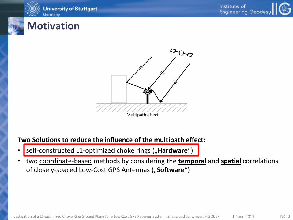
Two Solutions to reduce the influence of the multipath effect:
• self-constructed L1-optimized choke rings („Hardware“)
• two coordinate-based methods by considering the temporal and spatial correlations of closely-spaced Low-Cost GPS Antennas („Software“)
Multipath effect
1 June 2017 Investigation of a L1-optimized Choke Ring Ground Plane for a Low-Cost GPS Receiver-System , Zhang und Schwieger, FIG 2017

Introduction and Motivation
• Optimization of Antenna Shieldings Design of L1-optimized Choke Ring Ground Plane
Antenna Calibration
• Comparison of different Shieldings Test Scenario
Data Processing
Quality Analysis
Frequency Analysis
• Conclusion and Outlook
Structure
No. 4 1 June 2017 Investigation of a L1-optimized Choke Ring Ground Plane for a Low-Cost GPS Receiver-System , Zhang und Schwieger, FIG 2017
Optimization of Antenna Shieldings
No. 5 1 June 2017 Investigation of a L1-optimized Choke Ring Ground Plane for a Low-Cost GPS Receiver-System , Zhang und Schwieger, FIG 2017
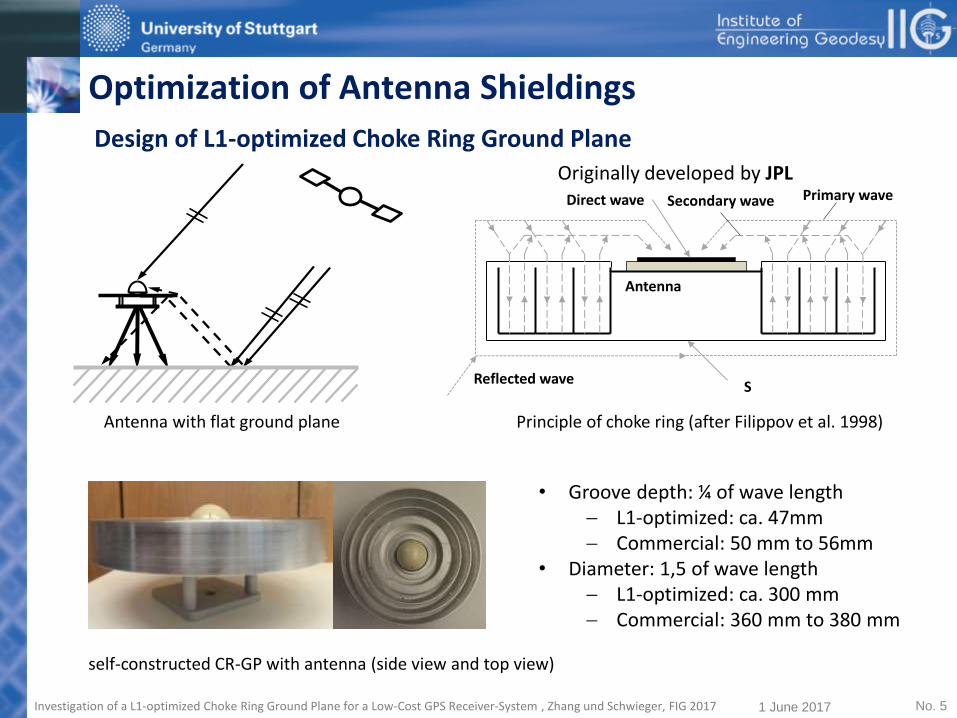
Antenna with flat ground plane
Direct wave
Reflected wave
Primary wave
Antenna
Secondary wave
S
Principle of choke ring (after Filippov et al. 1998)
Design of L1-optimized Choke Ring Ground Plane
self-constructed CR-GP with antenna (side view and top view)
Originally developed by JPL
• Groove depth: ¼ of wave length L1-optimized: ca. 47mm Commercial: 50 mm to 56mm
• Diameter: 1,5 of wave length L1-optimized: ca. 300 mm Commercial: 360 mm to 380 mm

Optimization of Antenna Shieldings
No. 6 1 June 2017 Investigation of a L1-optimized Choke Ring Ground Plane for a Low-Cost GPS Receiver-System , Zhang und Schwieger, FIG 2017
Antenna Calibration
E
60
120
30
150
75
45
15
N
S
Antenna Calibration Trimble 224100575 + Ground Plate
330
210
300
240
W
-10
-8
-6
-4
-2
0
2
4
6
8
10
E
60
120
30
150
75
45
15
N
S
Antenna Calibration Trimble 224100575 + Choke Ring
330
210
300
240
W
-4
-2
0
2
4
6
8
PCV of TBIII antenna
with flat ground plane [mm]
PCV of TBIII antenna
with choke ring ground plane [mm]
[mm][mm]
Calibration of TBIII antenna with flat Ground Plane and Choke Ring Ground Plane
PCV of TBIII antenna with flat Ground Plane and Choke Ring Ground Plane
PCV with Choke Ring Ground Plane: • smaller and more
homogeneous • Difference of the PCV
between antenna: -1,5 mm to 1,5 mm type antenna calibration is sufficient
Comparison of different Shieldings
No. 7 1 June 2017 Investigation of a L1-optimized Choke Ring Ground Plane for a Low-Cost GPS Receiver-System , Zhang und Schwieger, FIG 2017
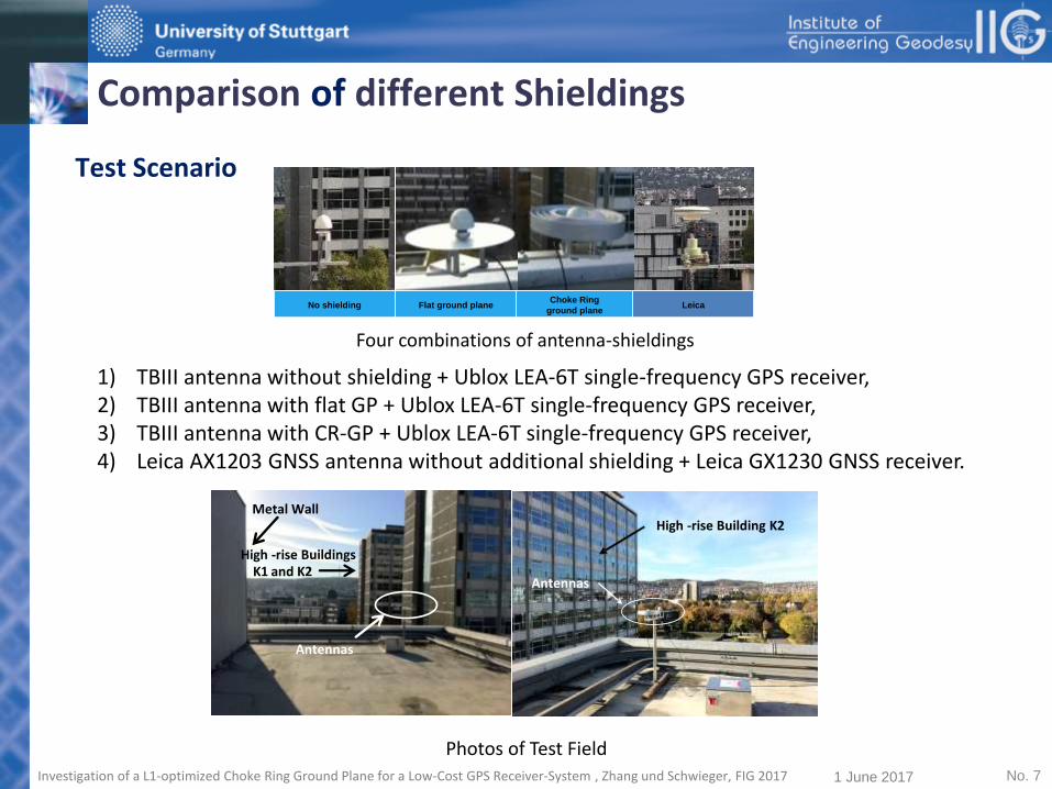
Test Scenario
No shielding Flat ground planeChoke Ring
ground planeLeica
1) TBIII antenna without shielding + Ublox LEA-6T single-frequency GPS receiver, 2) TBIII antenna with flat GP + Ublox LEA-6T single-frequency GPS receiver, 3) TBIII antenna with CR-GP + Ublox LEA-6T single-frequency GPS receiver, 4) Leica AX1203 GNSS antenna without additional shielding + Leica GX1230 GNSS receiver.
Four combinations of antenna-shieldings
Metal Wall
High -rise BuildingsK1 and K2
Antennas
Antennas
High -rise Building K2
Photos of Test Field

Comparison of different Shieldings
No. 8 1 June 2017 Investigation of a L1-optimized Choke Ring Ground Plane for a Low-Cost GPS Receiver-System , Zhang und Schwieger, FIG 2017
Test Scenario
Session Nr. Date Antenna and Shieldings P1 P2 1 24.-25. 10.13 TBIIII+ CR-GP TBIIII+ flat GP 2 27.-28. 10.13 TBIIII+ flat GP TBIIII+ CR-GP 3 26.-27. 04.14 Leica AX1203 TBIII without shielding 4 27.-28. 04.14 TBIII without shielding Leica AX1203
gon
do
la8,8 m4
,6 m
0,5
m
Metal Wall
Antennas
ca. 50mca. 100m
High-rise Building
P2
P1 Box
SSAPOS-Station
N
K2K1

Comparison of different Shieldings
No. 9 1 June 2017 Investigation of a L1-optimized Choke Ring Ground Plane for a Low-Cost GPS Receiver-System , Zhang und Schwieger, FIG 2017
Data Processing
Session Nr. Observation time (GPS-Time) 1 24.10.13 10:30:30 - 25.10.13 06:30:29 2 27.10.13 10:17:18 - 28.10.13 06:17:18 3 26.04.14 21:51:06 - 27.04.14 17:51:05 4 27.04.14 21:47:00 - 28.04.14 17:46:59
• 20 hours are cut from the original observation time for the data processing • averaged satellite period was considered (23 hours 55 minutes 54 seconds)
Results: baseline in UTM-system (East, North, Height)
sampling rate 1 Hz every second

Comparison of different Shieldings
No. 10 1 June 2017 Investigation of a L1-optimized Choke Ring Ground Plane for a Low-Cost GPS Receiver-System , Zhang und Schwieger, FIG 2017
Quality Analysis
Receiver
Ubox LEA-6T GPS-L1-Receiver
Leica GX1230 GNSS-Receiver
Antenna Trimble Bullet III Leica AX1203 Shielding - GP CR-GP - - Frequency GPS-L1 GPS-L1 GPS-L1 GPS-L1 GNSS
Qu
alit
y
Reliability (Percentage of Outliers)
𝑜𝐸 [%] 4.2 2.4 2.1 1.7 1.4 𝑜𝑁 [%] 4.6 3.0 2.6 2.7 1.4 𝑜ℎ [%] 4.0 2.8 2.1 2.3 1.4 𝑜𝑚 [%] 4.2 2.7 2.3 2.2 1.4
Accuracy (Standard
Devation-1σ)
𝑠𝐸 [mm] 6.8 5.6 3.4 3.8 3.5 𝑠𝑁 [mm] 10.1 7.9 4.9 5.5 4.8 𝑠ℎ [mm] 16.7 13.3 8.7 9.8 10.1 𝑠𝑝 [mm] 20.7 16.4 10.5 11.9 11.7
Results of Quality Analysis of antenna-shielding test (mean of P1 and P2)

Comparison of different Shieldings
No. 11 1 June 2017 Investigation of a L1-optimized Choke Ring Ground Plane for a Low-Cost GPS Receiver-System , Zhang und Schwieger, FIG 2017
Quality Analysis
Quality Analysis of antenna-shielding test (mean of P1 and P2)
0,0
5,0
10,0
15,0
20,0
25,0
TBIII TBIII+GP TBIII+CRGP Leica L1 Leica GNSS
Durchschnittlicher Ausreißeranteil [%] Standardabweichung Position [mm]Mean percentage of outliers [%] Standard Deviation Position [mm]
• Improvement of the standard deviation: CR-GP: ca. 50 %, Flat GP: 35 % • TBIII antenna with CR-GP can achieve a standard deviation of ca. 3 mm in east, 5 mm in
north and 9 mm in height in this reflexion intensive environment. • TBIII antenna with CR-GP has shown in this test a result, which is comparable with Leica AX
1203 antenna with GX1230 receiver

Comparison of different Shieldings
No. 12 1 June 2017 Investigation of a L1-optimized Choke Ring Ground Plane for a Low-Cost GPS Receiver-System , Zhang und Schwieger, FIG 2017
Frequency Analysis
𝑓𝛿𝜑(𝑡) =2
𝜆∙ &ℎ ∙ 𝑐𝑜 𝑠 𝐸𝑠 (𝑡) ∙ 𝐸𝑠 (𝑡
&−𝑑 ∙ 𝑠𝑖 𝑛 𝐸𝑠 (𝑡) ∙ 𝐸𝑠 (𝑡
• Frequency of multipath on the carrier phase Horizontal
Vertical
𝜆: wavelength (L1:19 cm) ℎ and 𝑑: vertical and horizontal distances between antenna and reflector 𝐸𝑠 and 𝐸𝑠 : elevation of the satellite and its change over time (velocity)
• Period (of coordinates’ time series) caused by the multipath effects in this test field: by the ground : period >20 minutes or frequency < 0.83 mHz by metal wall: period 5-30 minutes or frequency 0.55-3.3 mHz Generally: frequency which is less than 0.55 mHz is mainly caused by multipath signals from the ground

Comparison of different Shieldings
No. 13 1 June 2017 Investigation of a L1-optimized Choke Ring Ground Plane for a Low-Cost GPS Receiver-System , Zhang und Schwieger, FIG 2017
Frequency Analysis
0 0.5 1 1.5 2 2.5 3 3.5
x 10-3
0
5000
E
Periodogramm TBIII+CR-GP P1
0 0.5 1 1.5 2 2.5 3 3.5
x 10-3
0
1
2x 10
4
N
0 0.5 1 1.5 2 2.5 3 3.5
x 10-3
0
5x 10
4
h
Frequenz [Hz]
0 0.5 1 1.5 2 2.5 3 3.5
x 10-3
0
5000
E
Periodogramm TBIII+GP P1
0 0.5 1 1.5 2 2.5 3 3.5
x 10-3
0
1
2x 10
4
N
0 0.5 1 1.5 2 2.5 3 3.5
x 10-3
0
5x 10
4h
Frequenz [Hz]
0 0.5 1 1.5 2 2.5 3 3.5
x 10-3
0
5000
E
Periodogramm TBIII P1
0 0.5 1 1.5 2 2.5 3 3.5
x 10-3
0
1
2x 10
4
N
0 0.5 1 1.5 2 2.5 3 3.5
x 10-3
0
5x 10
4
h
Frequenz [Hz]
Periodogramm of coordinates’ time series of TBIII antenna: without shielding, with flat GP, with CR-GP on point P1
By applying the shielding, the energy between the 0 and 0.55 mHz is reduced considerably, and CR-GP reduced even more energy than the flat GP. Shieldings reduced mainly the signal from the ground and the CR-GP is more effective than the flat GP.

Conclusion • Description of the Design of a L1-optimized choke ring ground plane (CR-GP)
• Results of antenna calibration: PCV of the TBIII antenna with CR-GP are smaller and more homogenous than with flat GP. No individual antenna calibration of TBIII antenna with CR-GP necessary
• CR-GP is the best shielding, improvement of the standard deviation by using CR-GP is about 50 % and 35 % by using flat GP
• The standard deviation of TBIII antenna with CR-GP is 3 mm in east, 5 mm in north and 9 mm in height in the test filed which has many reflectors. The TBIII antenna with CR-GP shows in the test reliable and accurate results, which is comparable to the Leica AX 1203 GNSS antenna with GX1230 GNSS receiver.
• The frequency analysis shows that the shieldings reduce mainly the multipath signal from the ground and the CR-GP is more effective than the flat GP.
Conclusion and Outlook
No. 14 1 June 2017 Investigation of a L1-optimized Choke Ring Ground Plane for a Low-Cost GPS Receiver-System , Zhang und Schwieger, FIG 2017

Limitation: • CR-GP is not for all the application suitable because of its weight
• single GPS receiver-system has its limitation, if the baseline is long (more than 10 km), and it is also not really suitable for PPP (Precise Point Positioning) up to now, if the accuracy should be in mm or cm level. Because they receive only the L1-freuency, the ionospheric influence cannot be reduced in both cases.
However: • The introduced low-cost GPS receiver-system (costs up to 1000 €), which contains
the Ublox LEA-6T single-frequency GPS receiver and TBIII antenna with self-constructed L1-optimized CR-GP, can already obtain an accuracy in the range of millimetres which meets the requirements of geodetic precise monitoring for such as landslides, bridges and dams and so on.
• The difference of L1-wavelength of GPS, GLONASS, BeiDou, Galileo is not big introduced CR-GP is suitable for multi-GNSS single-frequency receiver!
Conclusion and Outlook
No. 15 1 June 2017 Investigation of a L1-optimized Choke Ring Ground Plane for a Low-Cost GPS Receiver-System , Zhang und Schwieger, FIG 2017

No. 16
Dr.-Ing. Li Zhang/Prof. Dr.-Ing. habil. Volker Schwieger
Institute of Engineering Geodesy, University of Stuttgart Geschwister-Scholl-Str. 24 D 70174 Stuttgart Germany Tel: +49-711-685-84049 / -84040 Fax:+49-711-685-84044 E-mail: [email protected]/[email protected]
CONTACTS
Thank you very much for your attention !
1 June 2017 Investigation of a L1-optimized Choke Ring Ground Plane for a Low-Cost GPS Receiver-System , Zhang und Schwieger, FIG 2017