investigation of air damping of circular and rectangular ... · nasa m *o 00 c d z c technical note...
TRANSCRIPT

N A S A
m *o 00 c
d z c
TECHNICAL NOTE N A S A e. /
__
INVESTIGATION OF AIR DAMPING OF CIRCULAR AND RECTANGULAR PLATES, A CYLINDER, AND A SPHERE
by Duvid G. Stephens and Maurice A. ScuvuZZo
Langley Reseurch Center Langley Station, Humpton, Va.
N A T I O N A L AERONAUTICS A N D SPACE A D M I N I S T R A T I O N WASHINGTON, D. C. A P R I L 1965
https://ntrs.nasa.gov/search.jsp?R=19650010805 2018-07-15T17:10:27+00:00Z

TECH LIBRARY KAFB, NM
I llllllllll1 lllll lllll ulll11111ll1llllll Ill 0354078
INVESTIGATION O F AIR DAMPING
OF CIRCULAR AND RECTANGULAR PLATES,
A CYLINDER, AND A SPHERE
By David G. Stephens and Maurice A. Scavullo
Langley Resea rch Center Langley Station, Hampton, Va.
N A T I O N A L AERONAUT IC$ AND SPACE ADMlN I STRATI ON
For sale by the Off ice of Technical Services, Department of Commerce, Washington, D.C. 20230 -- Price $1.00

INVESTIGATION OF A I R DAMPING
OF CIRCULAR AND RECTANGULAR PLATES,
A CYLINDER, AND A SPHERE
By David G. Stephens and Maurice A. Scavullo Langley Research Center
An investigation w a s conducted t o determine the mechanism of a i r damping exhibited by r ig id bodies of different shapes osc i l la t ing i n a pressure environ- ment. Circular and rectangular plates, as w e l l as a sphere and cylinder, were attached t o cantilever springs and the f r ee decay of an induced osc i l l a t ion was measured at pressure leve ls from atmospheric t o 4 x 10⁻² t o r r . D a t a are pre- sented t o show t h e e f fec t of pressure, vibratory amplitude, frequency, shape, and surface area on the a i r damping of the models. Results indicate tha t the magnitude of the a i r damping may great ly exceed the s t ruc tura l damping of t he system. The a i r damping associated with the plates i s d i r ec t ly proportional t o t h e pressure and amplitude and i s indicative of diss ipat ive loads proportional t o the dynamic pressure. F’urthermore, the p la te damping w a s found t o be inde- pendent of shape and i s a nonlinear function of t he surface area. The sphere and cylinder exhibit viscous damping character is t ics which are i n good agree- ment with available theory.
INTRODUCTION
The vibratory response of a mechanical system i s highly dependent upon the t o t a l damping. I n most s i tuat ions t h i s damping resu l t s from the act ion of several dissimilar d i ss ipa t ive mechanisms, one or more of which may be a func- t i on of t he operating environment. Some of t h e more common sources of energy diss ipat ion include in t e rna l hysteresis ( r e f . l), in te r face or j o in t f r i c t i o n (ref. 2), and external or a i r damping. The air damping i s dependent upon the magnitude of t he pressure environment and, therefore, deserves par t icu lar atten- t i o n i n studying t h e response of systems designed t o operate throughout a wide range of pressure o r density. If, f o r example, t he vibration t e s t s of a space vehicle are conducted under atmospheric pressure conditions, t he damping l eve l and consequently t h e response will be somewhat d i f fe ren t than i n the actual operating environment which involves reduced pressures. Thus the interpreta- t i o n and extrapolation of t he r e su l t s of such tes ts must include t h e e f fec ts of t h e pressure environment.

An object moving i n a f l u i d such as a i r may lose energy t o the surrounding medium as a r e su l t of one or more r e s i s t i ve e f fec ts . from viscous laminar boundary-layer f r ic t ion , sound radiation, and vortex for- mation and shedding. However, the r e l a t ive importance of each of these phenom- ena on the damping of a vibrat ing body i s not known. Results of previous inves- t iga t ions a re l imited t o the e f f ec t s of a s ingle loss phenomenon on the damping of specif ic objects. For example, t heo re t i ca l s tudies of the viscous damping forces experienced by a sphere and cylinder o sc i l l a t ing i n a f l u i d are discussed by Lamb ( r e f . 3 ) and by Stokes ( r e f . 4), respectively. When these objects a r e undergoing re la t ive ly low frequency osci l la t ions, theory predicts t h a t they w i l l experience forces proportional t o the velocity and the square root of the f l u i d density. These predictions were examined experimentally i n reference 5 i n which a cylinder was swung as a pendulum about one end and l imited damping measure- ments taken at several pressure leve ls . For the frequency examined (0.7 cps), good agreement w a s found with the theory. The damping of a "two-dimensional" p l a t e resul t ing from sound radiation i s discussed i n references 6 and 7. r i g id p l a t e o sc i l l a t ing such t h a t the f l u i d cannot pass over the edges i s theore t ica l ly shown t o experience damping forces d i r e c t l y proportional t o the density, velocity, and the square of the area although no experimental v e r i f i - cation i s indicated. A case i n which vortex e f f ec t s may have been predominant i s discussed i n reference 8. The air damping force experienced by a s m a l l cant i lever beam i s shown t o be proportional t o the square of the vibratory velocity.
The diss ipat ion may r e su l t
A
The purpose of t h i s paper i s t o present the r e s u l t s of an investigation of the charac te r i s t ics of t he a i r damping exhibited by r i g i d c i rcu lar and rectan- gular plates, a sphere, and a cylinder o sc i l l a t ing i n a pressure environment varying from atmospheric t o 4 x 10⁻² t o r r . The e f f ec t s of area, shape, vibra- tory amplitude, exci ta t ion frequency, and pressure a re examined.
SYMBOLS
A area of a panel, sq f t
a radius of sphere, cylinder, or disk, f t
2 b veloci ty squared damping coefficient, lb-sec sq ft
lb-sec f t
C viscous damping coefficient,
E energy of o sc i l l a t ing system, lb- f t
aE energy diss ipated per cycle, l b - f t
frequency of osci l la t ion, f cycles sec
2

k
2
m
P
t
U
W
X
Y
2 slope, f t (see f i g . 8)
length of p l a t e or cylinder, f t
vibratory mass, lb- see2 f t
pressure of chamber, t o r r
thickness of material, f t
vibratory velocity, f t / s e c
width of plate, f t
damping force, l b
vibratory amplitude, f t
6 logarithmic decrement, 1 l o g YO - Yn
P lb-secz f l u i d density,
f t 4
kinematic viscosi ty , ft2 - v sec
radians sec cu c i rcu lar frequency of osc i l la t ions ,
Subscripts:
a air
e external
i in t e rna l
3 j o in t
n nth cycle of vibration
0 i n i t i a l cycle of vibration
t beam t i p
3

X extraneous damping
1,2 designates cycle
max maximum
Dots over symbols denote derivatives with respect t o time.
APPARATlTS AND TEST PROCEDURE
Vacuum Equipment
The vacuum system used i n t h i s investigation i s shown schematically i n f igure 1. 30 inches high which was sealed t o a 6-inch s t e e l spacer. The s t e e l spacer provided access ports ( f o r e lectronic leads and vacuum l i n e s ) from the side rather than from the bottom of the chamber as i n a conventional b e l l jar system. The spacer was i n turn mounted on a s t e e l base plate; and the system was anchored t o a massive s t e e l and concrete block t o eliminate the transmission of vibratory energy from the apparatus t o the adjoining s t ructure . A ?-cubic- foot-per-minute mechanical pump was used t o obtain the desired pressure leve ls between the l i m i t s of 1 atmosphere and 4 x 10⁻² t o r r . between the pump and the chamber reduced the transmission of pump vibrations t o the system.
The chamber consisted of a g lass b e l l jar 18 inches i n diameter and
A f lex ib le coupling
Vibration Equipment
The equipment used t o study the damping of the various models within the vacuum chamber i s shown schematically i n f igure 2. frequency, one of two cantilever beams w a s employed t o support the models and
Depending upon the desired
provide the osc i l la t ion .
thicknesses of 1/8 and 3/8 inch and were tuned t o frequencies of 3.8 and
The beams, 19 inches long and 1/2 inch wide, had 4
Flex coupling 1
Figure 1.- Schematic of vacuum system. Figure 2.- Test apparatus and
instrumentation.
4

21.2 cps, respectively, by attaching a s m a l l mass t o the beam t i p . Each beam, machined from a single piece of s ta in less s tee l , had a re la t ive ly large foot f o r mounting the assembly t o the base p la te and a T-section at the t i p f o r attaching the models. mental vibratory mode of the cantilever beam. moved forward and imparted a s t a t i c deflection t o the beam. the slug was quickly retracted by the spring and the f r e e decay of t he model- beam system w a s studied.
A spring-loaded solenoid was used t o exci te the funda- When energized t h e solenoid slug
Upon de-energizing,
3 1 4 2 I n addition t o these beams, an aluminum beam 25- inches x 2 inches x - inch
was used t o study t h e damping charac te r i s t ics of three large p la tes at a f re - quency of 3.8 cps. Since t h i s study w a s conducted under atmospheric pressure conditions, t h e beam was deflected and released manually.
Instrumentation
The damped osc i l la t ions of t he model-beam system were monitored by means The output of t h i s gage of a s t r a i n gage attached near the root of t he beam.
w a s amplified and fed in to an electronic dampometer which measured the f r e - quency and logarithmic decrement of the osc i l la t ion .
A Bourdon gage and an ion gage were used t o measure the pressure i n the b e l l jar. The Bourdon gage w a s used from a pressure of 1 atmosphere t o 1 t o r r and the ion gage was used from 1 t o r r t o the lowest a t ta inable pressure i n the system ( 4 x 10⁻² t o r r ) .
Models
The damping was studied f o r t h e models shown and described i n t ab le I. The p la tes with surface areas of 15, 30, and 45 square inches and the sphere and cylinder, each having a projected surface area of 30 square inches, were used f o r most of the t e s t s . These models were selected t o examine the e f fec ts of shape and area on t h e a i r damping within the vacuum system. p la tes having surface areas between 12 and 39 square inches were used i n l i m - i t e d t e s t s t o b e t t e r define the damping-area relationship. tangular plates, having surface areas of 93.8, 152, and 240 square inches, were studied a t atmospheric conditions t o invest igate the poss ib i l i t y of applying the r e su l t s obtained f o r the s m a l l models t o la rger systems. The materials, from which the models were constructed, a re given i n t ab le I and were chosen t o maintain approximately t h e same weight f o r all models used i n a par t icu lar t e s t . All panels were machined with square edges.
The rectangular
The remaining rec- '
Test Procedure
The damping charac te r i s t ics of the beams alone, tuned t o 3.8 o r 21.2 cps by the addition of concentrated masses t o the t i p , were studied i n i t i a l l y . The selected model w a s then securely attached t o the t i p of the beam and damping of
5

t h e assembled system, tuned i n a similar manner t o a frequency of e i the r 3.8 o r 21.2 cps, was measured. t he vacuum chamber w a s essent ia l ly the same f o r each case. The chamber w a s pumped down t o the desired pressure l eve l and f o r a l l b u t , t h e lowest pressure l e v e l (4 x 10⁻² t o r r ) the pump was stopped while the t e s t points were taken. The beam was deflected by means of the solenoid and released. When the ampli- tude of t he ensuing osc i l l a t ion reached a pre-selected value, the output of the s t r a i n gage t r iggered the dampometer which measured the decay of t he osc i l la - t i o n u n t i l the amplitude reached 7/10 of the value f o r t he i n i t i a l reading. The damping i n terms of the log decrement was then calculated from
The basic procedure f o r measuring t h i s damping within
of the system was found t o be most expedient f o r measuring the damping and i so la t ing the e f f ec t s of t h e variables. The decay of the osc i l l a t ion was ana- lyzed over selected portions of the envelope and specified i n terms of logarith- mic decrement 6. For purposes of t h i s investigation, t he decrement i s physi-
4
1 yo 1 10 6 = - log - = - log - 7 Yn n n
where n was the number of cycles recorded between these amplitude l i m i t s . I n a l l cases the i n i t i a l def lect ion was of suf f ic ien t amplitude t o allow any undesirable t rans ien ts t o decay before a t e s t point was taken.
The decrement was measured a t various posit ions along the envelope t o determine the dependency, i f any, of t he damping on the amplitude. The ampli- tude associated with a t e s t point was determined i n a separate t e s t In which the dynamic def lect ion of the system was measured at the selected output levels . The deflection, at various posit ions along the beam and model, was determined by placing a s tylus a t the desired posit ion and measuring the resul t ing t race . For the amplitude range considered, the normalized mode shape of the tuned beam was found t o be independent of amplitude and the same f o r each assembly at a given frequency.
I n l imited t e s t s conducted t o examine extrapolation techniques, panels of considerably la rger area were examined f o r several amplitudes a t atmospheric pressure only, as s ize precluded in s t a l l a t ion i n the vacuum system. cedure w a s essent ia l ly the same. The damping of t he beam, tuned t o the f r e - quency of t he beam panel assembly (3.8 cps), was studied and then the t o t a l damping of t he beam-panel system was examined.
The pro-
ANALYSIS
a = - AI3 2E
I
I

as i s discussed i n reference 9. Two character is t ics of equation (1) should be noted. F i r s t , t h e relationship i s applicable for analyzing or interpret ing any damped osc i l la t ion regardless of the type of decay (viscous, velocity squared, and so for th) ; t ha t is, no assumption i s m a d e as t o the shape of the envelope. This e f fec t can be seen by considering a hypothetical case i n which an arbi- trary velocity time his tory i s available. Application of equation (1) yields
where AE i s the change i n k ine t i c energy between successive peaks and E represents t h e average of peak energy leve ls of t he system, t h e system, and umax i s the m a x i m velocity. Equation (2) reduces t o
m i s the m a s s of
A?3 2E
= 2 ( 3 )
%ax, 1 %ax, 2
This relationship i s the f i rs t term i n the ser ies expansion of log
A?3 which i s by def in i t ion the log decrement. The e r ror i n assuming t h a t 6 = - 2E i s t h a t involved i n dropping the higher ordered terms of t h e se r i e s which a re usually very s m a l l . various sources of damping. For example, i f t he energy loss i s a t t r ibu ted t o t h e combination of in te rna l dissipation, jo in t losses, and external losses, then the decrement can be wri t ten as
The second point t o be noted i s the additive nature of t he
mi + m . + m e m 2E 2E
6 = - = (4)
where AEi represents the in te rna l losses; mj, the jo in t losses; and m e , t h e external losses. are known, these losses can be subtracted from the t o t a l measured decrement t o y ie ld a value f o r t he remaining energy dissipation.
Thus, i f t h e losses a t t r ibu ted t o one or more sources
For the configurations under study, t he t o t a l decrement w a s measured throughout a wide range of variables. The decrement w a s writ ten as
+ma 6 = 2E ( 5 )
7

where aEX i s the t o t a l of a l l t h e extraneous damping of t he beam system such as t h e in te rna l hysteresis of t he beam, diss ipat ion at t h e beam support in te r - face, and so for th . The value of LIEx w a s accurately determined p r io r t o t e s t ing a par t icu lar configuration by tuning t h e beam alone t o the desired f r e - quency and measuring the decrement. assembled system w a s i solated and a t t r ibu ted t o t h e air resistance of t h e models and can be writ ten as
The additional damping measured f o r t h e
Once the a i r damping of t h e models w a s isolated, examination of t he e f fec ts o f each of the variables (pressure or density, amplitude, frequency, area, and shape) on the decrement o r more spec i f ica l ly the energy loss per cycle remained. diss ipat ive force or
AE I n t h i s case t h e loss per cycle i s equal t o the work done by the
If, f o r example, t h e forces a re viscous o r d i r ec t ly proportional but opposed t o velocity as discussed i n reference 8, the energy loss would be
where c may be a function of the density, area, and so forth, but independent of velocity $. velocity i s assumed t o be
Since t h e motion of t he models i s essent ia l ly harmonic, t he
y = you cos cut ( 9 )
f o r t he case of low damping. Hence
m = S,B” cyo 2 LU 2 cos 2 c u t d t
which when integrated gives
The corresponding t o t a l energy o r E i s simply
8

and hence
where m i s the osc i l la tory m a s s , and cu i s the circular frequency. Thus i n t h e viscous case the decrement i s independent of amplitude but i s a function of frequency .
If the damping i s proportional t o the velocity squared, a s i m i l a r calcu- l a t i o n i n which
w i l l y ie ld a decrement
which i s a l i nea r function of displacement and independent of frequency f o r a par t icu lar system.
When the data were analyzed and presented, the e f fec ts of pressure and amplitude were isolated t o determine, f o r a par t icular system, whether t he damping w a s viscous, velocity squared, or of some intermediate form. The data were then presented i n forms suggested by e i ther equation (13) or (13) t o determine the relationships between pressure, area, shape, frequency, and damping.
I n the case of t he sphere or cylinder, equations a re available f o r com- parison of t he experimental resu l t s with theory. The problem of a sphere per- forming pendulum osc i l la t ions of s m a l l amplitude i n an incompressible i n f i n i t e m a s s of viscous f l u i d has been t rea ted by Lamb and Stokes, references 3 and 4, respectively. The derivation of the resul tant force acting on the spherical surface yields a force component which i s l inear ly proportional t o and i n oppo- s i t i o n t o the velocity as follows:
where
X
P
a
cu
damping force
f lu id density
radius of sphere
c i rcu lar frequency of osc i l la t ions
9

Y kinematic viscosi ty
U veloci ty
U s i n g
where
C damping coefficient
m osc i l la tory m a s s
Hence the logarithmic decrement i s
m
The viscous damping force on a cylinder with a high length-radius r a t i o vibrating r ec t i l i nea r ly normal t o i t s length at s m a l l amplitudes has been cal- culated by Stokes. (See re f . 4 . ) The damping force i s given as
where a and 2 a re the radius and length of the the other symbols a re as previously defined.
Again se t t ing
yields
PRESENTATION AND DISCUSSION OF
The primary objectiva of the t e s t program w a s
(18)
cylinder, respectively, and
RESULTS
the i so la t ion and examina- t i o n of the e f f ec t of density on the air damping of the two- and three- dimensional shapes. This objective w a s accomplished by examining the
10

difference i n magnitude of t h e t o t a l system damping and the beam damping measured over a wide range of pres- sures. A t each pressure level, the damping w a s measured f o r several amplitudes of vibration so the e f fec t of amplitude could a l so be isolated and studied. By comparing the data from each of the systems, t he e f fec ts of frequency, shape, and area become evident. The relation- ships established by these data were compared with the measured damping of panels of much la rger area t o examine the va l id i ty of extrapola- t ion. The data which follow exem- p l i f y these points.
Tip deflection, in. ,0020-
0015L , I I I I 0 200 400 600
Presswe. torr
Figure 3 . - Variation of beam damping pressure. f = 3.8 cps.
- 803
with
Beam Damping
The damping associated w i t h t he fundamental mode of osc i l la t ion of the cantilever beam, tuned t o 3.8 cycles per second, i s presented i n figure 3 . These data served as a t a r e f o r obtaining the a i r damping of t he low-frequency assemblies and s i m i l a r r e su l t s f o r t he beam tuned t o 21.2 cycles per second were used i n the high-frequency cases. The damping factors, i n terms of the loga- rithmic decrement 6, are shown as a function of the pressure f o r several d i f - ferent t i p amplitudes (note suppressed zero). I n t h i s case, as well as those t o follow, the data points represent an average of f ive or more measured values. The t o t a l damping associated with the beam exhibits a near-linear dependency on pressure i n the range between atmospheric pressure and 100 to r r . Below 100 t o r r t he damping factors deviate f r o m t h i s l i nea r pressure relationship and approach values a t 4 x 10⁻² t o r r which a re most probably due t o the in te rna l hysteresis and jo in t f r i c t ion . No attempt w a s made t o i so l a t e these par t icu lar effects as the resu l t s served only as a t a r e . A t a l l pressures the magnitude of the damping i s proportional t o the t i p amplitude. The curve as presented w a s rerun periodically and w a s found t o be highly repeatable.
Total Damping of Beam-Model System
A typ ica l sample of t he data, as 'recorded, i s shown i n f igure 4 t o i l l u s t r a t e the re la t ive magni- tudes of t he beam and t o t a l
recorded f o r t he 30-square-inch rectangle mounted on the t i p of t he low-frequency beam i s pre- sented as a function of pressure
9 2 damping. The t o t a l damping 0 200 400 600 800
Pressure. torr
Figure 4.- Variation of t o t a l damping with pressure. f = 3.8 cps.
11

and amplitude. The amplitudes r e fe r t o t h e average deflection of the center of t he p la te during the damping measurement and correspond t o the beam t i p deflec- t ions shown i n t h e previous figure. increase i n the system damping with the addition of t he p la te . For example, an increase i n damping by a fac tor of approximately f ive i s noted i n the high- pressure region. t o the values measured f o r the beam alone i n t h e low-pressure region. This condition indicates t h a t no extraneous damping is. introduced in to the system with the addition of t he p l a t e and thus the additional damping may be a t t r i b - uted t o the a i r resistance.
It i s in te res t ing t o note the s ignif icant
A s t h e pressure i s decreased, t h e values of damping converge
O I 2 r
Amplitude, in. /
Oo8t
30 inp 0
Pressure, tcfr
( a ) 30-square-inch disk.
Amplitude, in
,006
J
0 200 400 600 800
Pressure. torr
(b ) 30-square-inch rectangle.
Figure 5.- Variation of air damping with pressure. f = 3.8 cps.
12
A separate tes t w a s con- ducted t o determine the effect , i f any, of t he b e l l jar on the damping. A 45-square-inch p la te w a s attached t o the beam (3.8 cps) and the damping recorded of sev- e r a l amplitudes a t atmospheric pressure. The b e l l jar w a s then removed and the t e s t rerun. Since the data obtained with and without the b e l l jar were essen- t i a l l y identical , it was con- cluded t h a t t h e presence of t he b e l l jar per se had no s igni f i - cant e f fec t on the damping of the models.
Damping of Two-Dimensional Models
Effect of pressure.- The dependency of the a i r damping on the pressure, and hence on the density of the t e s t medium, i s presented i n f igure 5. The air damping, obtained by .subtracting the beam damping from the t o t a l damping at corresponding pres- sures and amplitudes, i s shown f o r the 30-square-inch p la tes at 3.8 cps. The damping fac tor exhibits a l i nea r dependency on the pressure throughout the range examined. A strong dependency of t he damping on the amplitude of deflection i s also noted and indicates t he presence of a non- l i nea r damping phenomena. Iden- t i c a l trends were noted i n the

case of t he 15- and 45-square-inch p la tes and these resu l t s a re pre- sented i n a subsequent section on shape i n which a l l t h e data are compared.
EXf ec t of amplitude. - The var ia t ion of damping with amplitude f o r the two 30-square-inch configura- t ions i s presented i n f ig- ure 6. The trends existing i n these cases a re again representative of t he results obtained f o r t he other plates studied at 3.8 cps. amplitude examined, t h e damping i s a near-linear function of p la te deflec-
For the range of
Pressure, torr
I 2 3 4 .5 .6
Amplitude, in.
(a) 30-square-inch disk.
Figure 6.- Variation of air damping with amplitude. f = 3.8 cps.
t ion. Because of t h i s l i nea r dependency, the damping i s apparently of the velocity squared type as previously discussed. Thus, t he resistance force i s
1 proportional t o the dynamic pressure pu2 as would be found i n the case of a
panel immersed i n a steady stream of incompressible f lu id . It should be noted t h a t an extension of the fa i red l i nes w i l l not in te rsec t t he origin. It i s possible t h a t i n the low-amplitude range, the forces become viscous i n nature and therefore the amplitude dependency or slope of t he curve i s reduced.
Effect of frequency.- The e f fec ts of frequency on the damping-pre s sure - amplitude rela- t ionship observed i n the previous cases were examined by employing the beam having a tuned frequency of 21.2 cps. The decrements are presented i n figure 7 as a func- t i o n of pressure and amplitude f o r t he 30-square-inch disk. Except i n the very low pressure region, the damping i s again a l i nea r function of pressure as shown i n f igure 7(a). s t i f fness , amplitudes comparable t o those of t h e low-frequency case could not be obtained with the solenoid. Consequently, t h e e f fec t of amplitude on t h e air damping w a s examined by removing the b e l l jar and displacing t h e beam manually.
Because of the beam
O ' O l Pressure. torr .do
0 I 2 3 4 5
Amplitude, in.
(b) 30-square-inch rectangle.
Figure 6.- Concluded.

In the region of higher amplitudes, t h e damping i s again d i r ec t ly pro- port ional t o displacement as shown i n f igure 7(b). is decreased, however, the damping becomes less dependent upon ampli- tude as w a s found i n the low- frequency case.
A s the amplitude
6- ro
p 2 4-
5 2 2 -
u
m
ETfect of shape.- The e f f ec t s Pressure, ton
of p l a t e shape were examined by com- paring the damping fac tors asso- ciated with the c i rcu lar and rec-
(a) Variation of air damping with pressure. Amplitude 0.44 in.
measured over a wide range of pres- sure and amplitude while attached t o the beam of lower frequency, a r e summarized i n f igure 8. decrement 6 i s presented as a function of the parameter py/m where p i s the density of the a i r within the chamber, y i s the amplitude of the center of the plate,
The log
I
i s a l i nea r function of the param- e t e r py/m which i s indicat ive of veloci ty squared damping. For a
Figure 7.- Variation of air damping with pressure and amplitude. f = 21.2 cps.
given area, 6 = kpy/m where k i s the slope of the curve associated
with tha t par t icu lar area. p la tes are compared the values of k a re highly dependent upon the area.
When the r e su l t s f o r the c i rcu lar and rectangular a re seen t o be independent of shape but
Effect of area.- A detai led examination of the nonlinear dependency of the air damping on p la te area necessitated the use of the additional p la tes of surface areas between 1 2 and 39 square inches. t i o n a re shown i n f igure 9. The measured decrement i s presented as a function of p la te area f o r two par t icu lar amplitudes at each frequency. The functional
dependency was found t o be 6 = A , the exponent 4/3 being determined from the slopes of the four curves. on area i s greater than t h a t experienced by a s i m i l a r p l a t e i n a steady flow f i e l d but l e s s than the relationship discussed i n reference 6 f o r sound radiation damping.
The r e su l t s of t h i s examina-
4/3 It i s in te res t ing t o note t h a t the dependency
A2
These resul ts , obtained at atmospheric pressure, a re compared with a l l As previously the low-frequency da ta previously summarized.
found, the decrement 6 i s a l i n e a r function of py/m f o r a par t icu lar area (See f i g . 8. )
14

but t he slope Gm/py did not vary d i r ec t ly with area. Thus f o r comparison purposes, all the low-frequency data a re presented i n f igure 10 where the param- e t e r Gm/py i s shown as a func- t i o n of area. The atmospheric data of figure 9 a re represented by the c i r c l e s and the data from f igure 8 (s lopes) a re shown by the squares. The r e su l t s indi- cate t h a t the decrement
pyA4'3 for a l l the low- 6 = 22 m frequency data. I n the case of the high-frequency data, the same relat ionship i s adequate f o r predicting the damping f o r amplitudes greater than
~ O X I O - ~
I Freswre. torr "1 0 760
Area, in2
o r / 45
m 12
" - 8 30
B s 4
L .. D
g E
15
0 4 8 12 16 2 0 24 28 3 2 xlO"
PY, 1. m ft*
(a) Disks.
Figure 8.- Variation of air damping with parameter py/m for pla tes .
0.15 inch. amplitude and therefore cannot be represented by the empirical relationship.
Below 0.15 inch, the damping ceases t o be a l i n e a r function of
The application of the relat ionship developed i n the previous section t o p la tes of la rge area was examined. inches (p l a t e area minus area of beam overlay) were selected t o provide an order-of-magnitude var ia t ion i n s ize . pressure f o r th ree amplitudes a re shown i n f igure 11 and are seen t o be i n excellent agreement with the empirical relationship. Thus it appears t h a t the relationship can be applied d i r ec t ly t o obtain the a i r damping of p la tes under conditions similar t o those encountered i n t h i s investigation. In more general cases, it appears t h a t damping measurements under atmospheric conditions can be extrapolated by using the functional relationship found t o ex i s t between the variables.
P la te areas of 71.3, 128, and 220 square
The decrements measured a t atmospheric
Apparent mass effects . - When the e f f ec t s of pressure environ- ment on the vibratory response of a system are considered, fre- m
quency considerations are a l so of in te res t . The vibratory object r
experiences not only forces w h i c h oppose the velocity (damping B L
5
F E
::
a forces ) but also forces propor- t i o n a l t o the acceleration which e f fec t ive ly a l t e r the mass as discussed i n reference 3. To examine the importance of t h i s effect , frequencies were measured f o r the 30-square-inch c i rcu lar plate, while it w a s attached t o both the high- and low-frequency
Preswre. ioTr
0 760 0 572 0 381
0 0.040 Slope k.5.0 A 189
8
4
0 A .8 1.2 1.6 2.0 2.4 2.8 32xIC
(b) Rectangles,
Figure 8. - Conclude&.

Amplitude,
Slopes 413
co
002
(a1 f = 3 8 c p s
,001
Slopes 4/3 (b) f = 21 2 cps
02 05 I 2 5 Area, sq f t
0001 I, Figure 9.- Variation of air damping
with area.
Area, sq fi
Figure 10.- Variation of parameter Gm/py with area.
beams. t ab le I1 as a function of pressure and amplitude. I n the low-frequency case a very s l igh t increase ( l e s s than 0.3 percent) i n frequency was noted as the pressure and hence apparent mass was decreased. No ef fec t of pressure could be detected i n the high-frequency case; thus, within the scope of t h i s study apparent mass ef fec ts are con- sidered t o be negligible.
The frequencies a re shown i n
I
I
Damping of Three-Dimensional Models
Sphere.- The air damping expe- rienced by the sphere with a projected surface area of 30 square inches i s shown i n f igure 12. The decrement, presented as a function of pressure and amplitude, i s essent ia l ly propor- t i o n a l t o the square root of the pres- sure o r density and i s v i r tua l ly inde- pendent of the amplitude. The independence of the air damping with amplitude i s indicat ive of viscous dampihg forces as predicted by Lamb. ( See r e f , 3. ) theore t ica l ly predicted viscous force would y ie ld the var ia t ion of damping with pressure shown by the dashed
The magnitude of the
curve; these resu l t s a re i n very good agree- ment with the experimental data. r e t i c a l decrement
The theo-
m
appears t o be quite adequate f o r the predic- t i o n of the damping.
Cylinder.- Similar r e su l t s obtained f o r the cylinder a re shown i n f igure 13 and a re compared with the theory of Stokes f o r an i n f i n i t e cylinder. Again, the decrement i s proportional t o the square root of the den- s i t y and i s i n excellent agreement with the theory i n the case of low amplitude. A t high amplitudes, however, a discrepancy of
3.6
h

t he damping with amplitude is noted pos- s ib ly because of end e f f ec t s o r p a r t i a l separation of the flow. However, the
I relationship
50r
> ,9
i s probably adequate f o r predicting the
It should be noted t h a t i n the cases of the sphere and cylinder, no var ia t ion of frequency with pressure was noted through-
t damping i n most engineering applications. CQ
l out the pressure range examined.
Experimental Theoretical
Amplitude. in.
Area, sq ft
I
I
I 0 200 400 603 800
I Pressure, torr
Figure 12.- Variation of air damping with pressure for the sphere. f = 3.8 cps. a
g ,g
5 m a
a
Figure 11.- Variation of param- eter Gm/py for large areas.
Experimental Theoreticol
Amplitude, in 0 .46 0 29
0 .I6 a .09
I
0 200 400 600 800 Pressure. torr
Figure 13.- Variation of air damping with pressure for the cylinder. f = 3.8 cps.

CONCLUSIONS
An investigation has been conducted t o determine the a i r damping exhibited by r ig id two- and three-dimensional shapes osc i l la t ing i n a pressure environ- ment ranging from 4 x 10⁻² t o r r t o 760 to r r . considered i n t h i s investigation, the following conclusions are noted:
Within the range of variables
1. For systems having a re la t ive ly large r a t i o of area t o mass, t he magni- tude of t he a i r damping may great ly exceed the damping a t t r ibu ted t o a l l other sources. Values of air damping, an order of magnitude greater than t h e struc- tural damping, were observed i n these t e s t s .
2. The damping factors associated with the two-dimensional p la tes exhibit a l i nea r dependency on pressure and, except f o r re la t ive ly low amplitudes, a near-linear dependency on amplitude. Thus t h e damping forces are apparently proportional t o the dynamic pressure.
3. For t he plates, t he damping i s independent of shape and var ies with the 4/3 power of t h e area.
4. The empirical relationship which best describes the dependency of the air damping of t he plates on the variables, air density p, amplitude y,
, where K i s equal t o 22 i n U.S. cus- pyA4I3 m a rea A, and mass m, i s 6 = K
tomary uni t s . u
5. The damping fac tors associated with the sphere are essent ia l ly propor- t i o n a l t o the square root of the density, independent of t he vibratory ampl i - tude, and i n good agreement with available theory based on viscous damping forces .
6. A t low amplitudes the cylinder exhibits damping factors i n excellent agreement with those predicted by viscous theory. damping exceeds theore t ica l predictions - possibly because of end ef fec ts or flow separation.
A t higher amplitudes the
7. The response frequency i s v i r tua l ly unaffected by changes i n pressure and amplitude; therefore, apparent mass ef fec ts are considered t o be negligible.
Langley Research Center, National Aeronautics and Space Administration,
Langley Station, Hampton, Va., December 9, 1964.
18

REFERENCES
1. Crandall, Stephen H.: On Scaling Laws f o r Material Damping. NASA TN D-1467, 1962.
2. Lazan, B. J.; and Goodman, L. E.: Material and Interface Damping. Data Analysis, Testing, and Methods of Control. Vol. 2 of Shock and Vibration Handbook, C y r i l M. H a r r i s and Charles E. Crede, eds., McGraw-Hill Book Co., Inc., 1961, pp. 36-1 - 36-46.
3. Lamb, Horace: Hydrodynamics. Sixth ed., Dover Pub., 1945.
4. Stokes, G. G.: On the Effect of Internal Fr ic t ion of Fluids on the Motion of Pendulums. Trans. Cambridge Phil . Soc., vol. I X , p t . 11, 1851, pp. 8-106.
5. Stuart, J. T.; and Woodgate, L.: Experimental Determination of the Aero- dynamic Damping on a Vibrating Circular Cylinder. Rept. No. F.M. 1992, B r i t . N.P.L. (Rept. No. 16,375, A.R.C.), Dec. 8, 1953.
6. Hubbard, Harvey H., and Houbolt, John C.: Vibration Induced by Acoustic Waves. Engineering Design and Environmental Conditions. V o l . 3 of Shock and Vibration Handbook, Cyril M. H a r r i s and Charles E. Crede, eds., McGraw-Hill Book Co., Inc., c.1961, pp. 48-1 - 48-57.
7. Rayleigh, (Lord): The Theory of Sound. F i r s t Am. ed., vol. 11, Dover Publ., 1945.
8. Baker, W. E.; and Allen, F. J.: The Damping of Transverse Vibrations of Thin Beams i n Air. Rept. No. 1033, B a l l i s t i c Res. Labs., Aberdeen Proving Ground, Oct. 1957.
9. Thomson, W i l l i a m Tyrrell : Mechanical Vibrations. Second ed., Prentice- H a l l , Inc., c.1953.
10. Keulegan, Garbis H.; and Carpenter, Lloyd H.: Forces on Cylinders and Plates i n an Oscil lating Fluid. Res. Paper 2857, Jour. Res. of N a t . Bur. Standards, vol . 60, no. 5, May 1958, pp. 423-440.
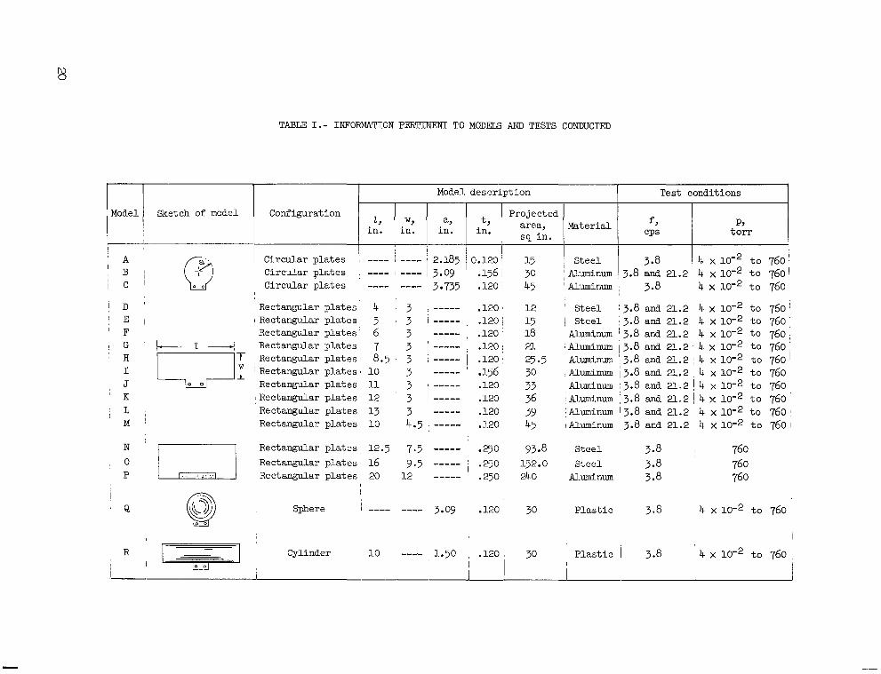
TABLE I.- INFORMATION PERTINEW TO MODELS AND TESTS CONDUCTED
I I I Model description
3 735 Circular plates ---- ---- I
I D ' Rectangular plates 4 3 , ----- E l I Rectangular p la tes ] 5 3 -----
R ~ r t . n n m i l a r n l n t p c . 6 3 ----- v--- r----- - -. - - - I_ , Rectangular p l a t e s , 7 3 ----- Rectangular plates 8.5 3 , -----
' F
' H I J
' K
! G k 2 - 1
, L ~i
i_' N
, o P
Rectangular p l a t e s , Rectangular plates Rectangular plates Rectangular plates Rectangular p l a t e s ,
Rectangular plates Rectangular plates
t, in.
0.120 .156 .120
.120
.120
.120
.120
.120
.156
.120
.120
.120
.120
12.5 7.5 ----- .250 16 9.5 ----- .250
I ..
Cyllnder io ---_ 1.50 , .120 i I
I
Projected
15 1 Steel 30 :Aluminum 45 l~luminum
12 ' Steel 15 1 Steel 18 Aluminum
Test conditions
CPS t o r r
I
4 x io-2 t o 760 \
4 x to 760: 4 x 10⁻² t o 760 4 x t o 760,
3.8 14 x t o 760
4 x t o 7601 3.8 and 21.2
3.8
3.8 and 21.2 3.8 and 21.2 3.8 and 21.2
21 I Ahminun 3.8 and 21.2 25.5 Aluminum 3.8 and 21.2 30 cAh"m 13.8 and 21.2
Muminum 3.8 and 21.~2 36 Aluminum 3.8 and 21.2
Aluminum 13.8 and 21,2 39 45 iAh"num 3.8 and 21.2
33 I
4 x t o 760' 4 x t o 760' 4 x io-2 t o 760 4 x 10⁻² t o 760 4 x t o 760 4 x 10⁻² t o 760 1
4 x 10⁻² t o 760 I
93.8 Steel 3.8 I 760 152.0 Steel 3.8 760 24 0 Aluminum 3.8 760
30 Plas t ic 3.8 4 x t o 760
, I I
30 Plas t ic I 3.8 ~ 4 x t o 760

Configuration 189 torr
30 in. 0 0.04 torr
TABLE 11.- EFFECT OF PRESSURE ON FREQUENCY
3 - 770 3.770
3 770
3.771
Amplitude
3 771
3 771
3 772
3 * 772
0.514
- 323 .181
.io3
21.17
21.28
21.26
21.20
0.024
.014
.010
.008
20 99
21.21
21.15
21.26
Frequencies for pressures of -
3 767
3.763
3.763
3.764
3 767
3.7@
3.768
3.768
21.23
21.23
21.29
21.29
21.20
21. 29
21.22
21.26
NASA-Langley, 1965 L-3806 21

“The aeronautical and space activities of the United States shall be conducted so ar fo contribute . . . to the expansion of human knowl- edge of phenomena in the atmosphere and space. The Administration shall provide for the widest practicable and appropriate dissemination of information concerning its activities and the results thereof.”
-NATIONAL AERONAUTICS AND SPACE ACT OF 1958
NASA SCIENTIFIC AND TECHNICAL PUBLICATIONS
TECHNICAL REPORTS: important, complete, and a lasting contribution to existing knowledge.
TECHNICAL NOTES: of importance as a contribution to existing knowledge.
TECHNICAL MEMORANDUMS: Information receiving limited distri- bution because of preliminary data, security classification, or other reasons.
CONTRACTOR REPORTS: Technical information generated in con- nection with a NASA contract or grant and released under NASA auspices.
TECHNICAL TRANSLATIONS: Information published in a foreign language considered to merit NASA distribution in English.
TECHNICAL REPRINTS: Information derived from NASA activities and initially published in the form of journal articles.
SPECIAL PUBLICATIONS: Information derived from or of value to NASA activities but not necessarily reporting the results .of individual NASA-programmed scientific efforts. Publications include conference proceedings, monographs, data compilations, handbooks, sourcebooks, and special bibliographies.
Scientific and technical information considered
Information less broad in scope but nevertheless
Details on the availability of these publications may be obtained from:
SCIENTIFIC AND TECHNICAL INFORMATION DIVISION
NATIONAL AERONAUTICS AND SPACE ADMINISTRATION
Washington, D.C. PO546