investigation of c-mn-b steel after hot deformation · possibility to compare the hot ductility of...
TRANSCRIPT
119
Volume 28
Issue 2
February 2007
Pages 119-125
International Scientific Journal
published monthly as the organ of
the Committee of Materials Science
of the Polish Academy of Sciences
Archives of Materials Science and Engineering
© Copyright by International OCSCO World Press. All rights reserved. 2007
Investigation of C-Mn-B steel after hot deformation
N. Wolañska*, A.K. Lis, J. LisInstitute of Materials Engineering, Faculty of Materials Processing Technology and Applied Physics, Czestochowa University of Technology, ul. Armi Krajowej 19, 42-200 Czestochowa, Poland* Corresponding author: E-mail address: [email protected]
Received 12.10.2006; accepted in revised form 25.01.2007
ABSTRACT
Purpose: Microstructure investigations after hot deformation carried out on the low carbon-manganese steel with addition of boron was presented in this work. The non-metallic inclusion influence on the microstructure and type of crack mechanism was shown.Design/methodology/approach: The hot ductility investigations were done on tensile test machine. The ductility of the steel was measured by reduction of area during the extension test in the temperature range from 700oC to 1200oC. The test was carried out with two different strain rates 0.01s-1 which is characteristic for the continuous casting process and 6.5s-1 which is characteristic for rolling of heavy plates and billets. The deformation microstructures of investigated steel after the hot extension tests and the chemical composition of non-metallic inclusion were established and characterized by optical microscopy and scanning electron microscopy with EDX.Findings: The established ~30 % ductility minimum of investigated steel with 0.01s-1 strain rate, was located in the temperature range from 900oC to 1000oC. This temperature range correspond with band straightening operation in the continues casting process. For fast strain rate 6.5s-1 the minimum of hot ductility equals ~65% reduction of area value. The structure after air cooling ferrite-bainite and ferrite-pearlite microstructures were observed. The inclusions in deferent size from 0.6 to 4 µm and different shape which are MnS and SiO2 inclusions with some other elements like Al2O3 and MnO were observed.Practical implications: Low carbon steel with addition of boron is produced by continuous casting process where straightening of the strand is taken place close to 900oC. This temperature corresponds with hot ductility minimum for investigated steel.Originality/value: Available literature concerns investigations of low carbon steels but without boron addition, which expect to have strong influence on the position of the hot ductility minimum.Keywords: Ductility; Hot ductility curves; Non-metallic inclusions; Cracks
MATERIALS MANUFACTURING AND PROCESSING
1. Introduction
Nowadays in practical conventional continuous casting of steel is to straighten the strand at the high temperature end of ductility trough (>900oC). All precautions are taken to edge cracking occurs. Dynamic recrystallisation cannot occur during
straightening owning to the low strain (2-4%) because the improvement in ductility is much smaller then indicated by the normal tensile hot ductility curve where strains are much greater, what was presented in the work [1-5]. The hot deformation ability of steel can be observed on ductility curves where reduction of area is in the function of temperature. The minimum in the %RA-T curves (the bottom of the trough) can be used to characterize the
1. Introduction
120 120
N. Wolañska, A.K. Lis, J. Lis
Archives of Materials Science and Engineering
depth and the width of the ductility trough, what gives the possibility to compare the hot ductility of different continuous cast steels slabs, and may be used to predict the steel susceptibility to transverse cracking during continuous casting in practice. Thus, a deeper and wider trough is an signal of a larger probability of transverse cracking during the unbending operation in the continuous casting machine.
Work [2] indicates that the higher bending loads may not be a problem because ferrite and austenite are present together and ferrite is softer then austenite. The temperature needs to be about 30oC below the Ar3 to make sure that ferrite is present before bending [1-5].
2. Experimental The chemical composition of the investigated steel is given in
Table 1. The examined killed low carbon steel has boron addition in amount of 60 ppm and was continuously cast. The cylindrical tensile samples of 10 mm dia. and 120 mm length, were machined with their longitudinal axes parallel to the casting direction, from regions near the slab surface. In this way the tensile strain was applied transverse to the solidification growth direction, thus more closely simulating the actual straightening operation.
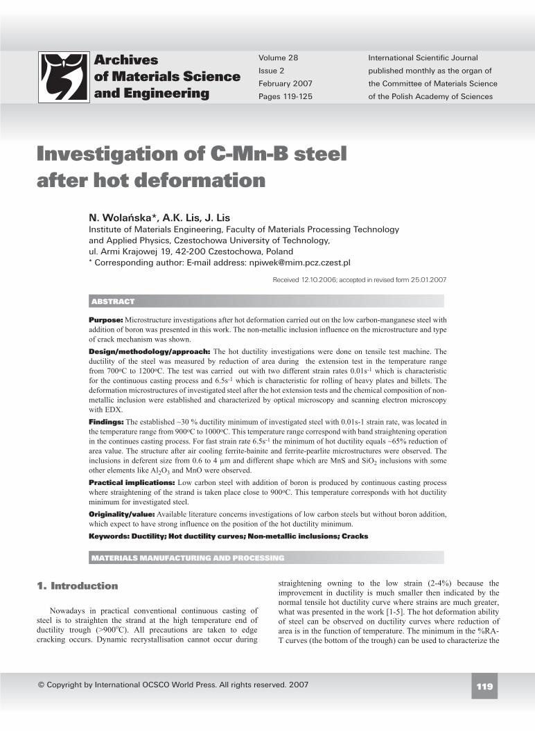
The tensile tests were performed using a Gleeble 3500 machine. The thermomechanical cycle used to simulate the straightening operation is shown schematically in Figure 1. Heating to 1300oC was carried with 20oC/s heating rate and the soaking time at this temperature was 1 minute. Cooling to the test temperature in the range 700-1200oC was performed with a cooling rate of 10oC/s. The temperature was measured and controlled using a thermocouple spot welded to the specimen’s surface. The effect of deformation was investigated at two different strain rates. The first one is used during a continuous casting process = 0.01 s-1 and the second one is characteristic for rolling of heavy plates and billets = 6.5 s-1. Finally, the test specimens were cooled in air. From a thermodynamic point of view, heating to 1300oC should be enough to dissolve most particles in the steel matrix.
The cooled samples were sectioned longitudinally with respect to the rolling direction for metallography of the fracture subsurface region. The deformation microstructures were characterized by optical microscopy and scanning electron microscopy with EDX technique.
3. Results
3.1. Hot ductility curves
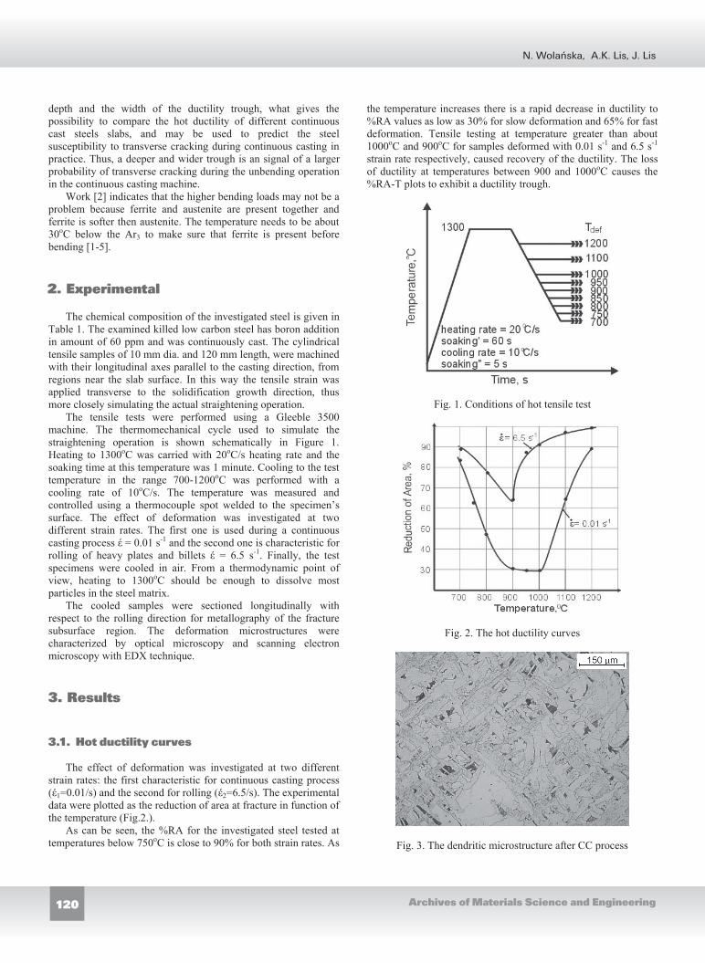
The effect of deformation was investigated at two different strain rates: the first characteristic for continuous casting process ( 1=0.01/s) and the second for rolling ( 2=6.5/s). The experimental data were plotted as the reduction of area at fracture in function of the temperature (Fig.2.).
As can be seen, the %RA for the investigated steel tested at temperatures below 750oC is close to 90% for both strain rates. As
the temperature increases there is a rapid decrease in ductility to %RA values as low as 30% for slow deformation and 65% for fast deformation. Tensile testing at temperature greater than about 1000oC and 900oC for samples deformed with 0.01 s-1 and 6.5 s-1
strain rate respectively, caused recovery of the ductility. The loss of ductility at temperatures between 900 and 1000oC causes the %RA-T plots to exhibit a ductility trough.
Fig. 1. Conditions of hot tensile test
Fig. 2. The hot ductility curves
Fig. 3. The dendritic microstructure after CC process
2. Experimental
3. Results
3.1. Hot ductility curves

121
Investigation of C-Mn-B steel after hot deformation
Volume 28 Issue 2 February 2007
Table 1. The chemical composition of the investigated steel
C Mn Si P S Cr Ni Cu Mo Sn B N20.1 0.47 0.08 0.014 0.023 0.08 0.05 0.17 0.014 0.009 0.006 0.009
Fig. 4. Microstructure of a sample deformed at 750oC with strain rate 0.01s-1
Fig. 5. Microstructure of a sample deformed at 950oC with strain rate 0.01s-1
3.2. Microstructure
The deformation microstructures were characterized by optical microscopy and were taken from the neck of the sample close to the failure. In Figure 3 the dendritic microstructure after continuous casting process, which can be seen before experiment, is shown. Structures after deformation are shown in Figures 4-8. The structure in the Figure 4 consists of ferrite and pearlite grains on the deformed prior austenite grains boundaries. In the space between the ferrite-pearlite structure the bainite grains can be seen. In the Figure 5 the structure consists of Widmanstätten ferrite on the prior austenite grain boundaries and bainite with acicular ferrite. The zig-zag shape cracks with inclusions inside can be observed. Similar structure can be observed in the Figure 6 but without cracks. The microstructures in Figures 4-6 present the samples after deformation with strain rate 0.01s-1. In the Figure 7
Fig. 6. Microstructure of a sample deformed at 1200oC with strain rate 0.01s-1
Fig. 7. Microstructure of a sample deformed at 700oC with strain rate 6.5s-1
Fig. 8. Microstructure of a sample deformed at 950oC with strain rate 6.5s-1
3.2. Microstructure

122 122
N. Wolañska, A.K. Lis, J. Lis
Archives of Materials Science and Engineering
the structure consists of polygonal ferrite and also ferrite with elongated grains. The ferrite structure is recovered and partially recrystalized. In Figure 8 the structure consists of ferrite grains with different shape and little cracks just after the failure surface can be seen.
3.3. Non-metallic inclusions
The chemical composition of non-metallic inclusions was established by EDX analyses of the samples surface with and without etching. The structure was taken from different parts of samples. The Figure 9 present the etched sample. The inclusions which were analyzed are in different sizes from 0.6 to 4 µm and mostly there are: MnS with round shape and SiO2 in different shapes but always with some other elements like Al2O3 and MnO. In Figure 11 the etched surface with long inclusions is shown.
In the Figure 9 MnS inclusion with other elements like Al and Si can be seen (1). Si could form oxides around the MnS phase – light ring around the inclusion – or some parts of the inclusion – black part on the bottom. Inclusion with 4µm in diameter occurs with a not very big void – 8µm in length – but in the neighborhood under the surface there is a bigger microcrack on the grain boundary. There is silicate oxide with diameter 0.65µm inside a ferrite grain (2) and no void around that inclusion. Fe peaks in the EDX spectra (Fig. 10.) originate from the matrix. MnS inclusion with some silicate oxide around with diameter 1.3µm occurs on the grain boundary inside a 4µm long void (3). There was also indicated silicate oxide inside 4µm long void with a diameter of 1.3µm within a ferrite grain. The surface is covered by many microvoids, which occurs inside grains as well as on the grain boundary.
In Figure 11 the whole inclusion is a complex of many elements like Al, Si, Ca, Mn, S which can create oxides and other phases. They formed a very long inclusion ~24µm length. The void around it is not much longer.
Fig. 9. Inclusions in the sample neck (sample deformed at 900Cwith strain rate 6.5s-1), the EDX spectra with 10kV energy is given in Fig. 8
On the sample without etching there were found inclusions like silicate oxide,. MnS phase with some silicate oxide on it and MnS with silicate oxide around. All inclusions are smaller than
2.5µm. The small voids on the surface used to contain inclusions but probably they were removed during polishing.
All analyzed inclusions were bigger than 0.5µm because of the size limitations of the beam in EDX analyses. To determine the chemical composition of inclusions smaller than 0.5µm, TEM microscopy will be used in the future. Inclusions with bigger diameter than 1 µm occur in the structure in different places e.g. inside the grains but also at the grain boundary. In the sample neck they are always inside voids, where the influence of deformation occurred.
Fig. 11. Inclusions in the sample neck (sample deformed at 1200C with strain rate 6.5s-1), the EDX spectra with 10kV energy are given in Fig. 10
4. Discussion The microstructure in the sample neck depends on the test
temperature and the strain rate of deformation. One of the factors, which has a strong influence on the microstructure is the temperature of deformation. The temperature of deformation can be divided into three zones: before, in and after the minimum of hot ductility. The microstructure after deformation depends on what kind of microstructure were present before deformation. In the lower temperature of deformation (700-9000C) there were austenite and ferrite in the structure. Above those temperatures there was only austenite in the sample structure before deformation.
In the temperatures close to 9000C (the minimum of hot ductility) there are a lot of cracks in the sample’s neck. The “zigzag” shape cracks change the direction of fracture in 90o. In this temperature the sample’s necks are much shorter than in others. In the temperatures before the minimum of hot ductility the austenite and ferrite phases are present in the structure before deformation. The volume fraction of ferrite grains increase with the decrease of the temperature and the ductility grows as well. In the hot ductility minimum austenite and nuclei of ferrite grains are present in the structure during deformation at 900oC. Above the Ar3 temperature (over 950oC) only austenite was present.
The microstructure in the sample neck after air cooling changed with the temperature of deformation. For the deformation at 700oC the microstructure is made of the ferrite grains (Fig. 4.). The ferrite recovered during the deformation and partially
3.3. Non-metallic inclusions
4. Discussion

123
Investigation of C-Mn-B steel after hot deformation
Volume 28 Issue 2 February 2007
1 2
3 4
Fig. 10. The EDX spectra of inclusions showed in Fig. 9. taken with 10kV energy
1 2
Fig. 12. The EDX spectra of inclusions showed in Fig.11. taken with 10kV energy
recrystalized but only in the sample deformed with high strain rate. For the samples deformed with lower strain rate, and at the region where both austenite and ferrite phases were present during deformation, the structure is made of polygonal ferrite, which had nucleated on the prior austenite grain, and bainite with acicular ferrite. The volume fraction of acicular structure increases with
the temperature. In the hot ductility minimum zone the microstructure is changed to the Widmanstätten ferrite on the prior austenite grain boundaries and bainite with acicular ferrite [6-9]. In this zone the zig-zag shaped cracks with inclusions inside can be found. In the zone above minimum of hot ductility the microstructure is made of very long needle-shaped ferrite
Si
S

124 124
N. Wolañska, A.K. Lis, J. Lis
Archives of Materials Science and Engineering
grains (it can be Widmanstätten ferrite, bainite or even martensite). The cracks which were observed in the minimum of the hot ductility do not appear at those test temperatures. That is because of dynamic recrystalization of austenite.
Non metallic inclusions occur in steels and for a long time they have been considered as an unwanted fraction which should be removed as completely as possible during the steel making process in order to improve the quality of steel.
The inclusions have been known to be detrimental to the mechanical properties of steel since they act as nucleation sites for microvoids and cracks [6,10-13]. However the role of some fine inclusions as inoculants has attracted much attention and certain inclusions dispersed in steel can provide potential sites for the heterogeneous nucleation of intergranular ferrite during the austenite-ferrite transformation what could provide to possibility of controlling the microstructure and mechanical properties of steel. There have been some non-metallic inclusions reported to be potent for the nucleation of intergranular ferrite such as Ti2O3 (titanium oxide), SiO2, Al2O3, MnO·SiO2 (manganese silicate), MnS, TiN, VN but the potency of some inclusions isn’t clear [14,15]. Shin et al. found that allotriomorphic ferrite was formed along prior austenite grain boundaries and that the austenite-ferrite transformation did not propagate significantly from prior austenite grain boundaries into austenite grains. And a large number of intergranular polygonal ferrite islands are also observed which were indicated by non-metallic inclusions. Inclusions, which were found in the investigated steels, were thermodynamically stable over a range of phase transformation temperature and in lower temperatures.
Fine non-metallic inclusions, in contrast to inclusions with bigger size, affect the properties of steel in a quite different manner by increasing the strength and modifying the grain growth characteristics and recrystallization of steel. A majority of fine inclusions have a diameter below 0.5µm and most fine inclusions have a spherical or close to spherical shape. They could be investigated only with electron microscopy techniques [16].
The most frequent inclusions in the present steel are sulphides. Sulphide creates with iron the precipitation of FeS, which has a melting point of 1190C and can form a liquid phase in the grain boundaries when steel is reheated to the temperature in the range 900÷1200C. This fact may cause cracking during plastic deformation and because of that manganese is added to the chemical composition of steel. MnS has higher melting point (1610C) than FeS and all its eutectics. Therefore failures at high temperatures are avoided. MnS occurs in steel in different forms: from round shape to irregular angular shape and often has varying amount of other elements in solid solution [15-18]. In the investigated steel, manganese sulphide occurs alone but sometimes with other elements surrounding it or inversely (Fig. 9, 11.) what could be called duplex or complex inclusions. The shape and percentage deformation depends not only on the applied force but also of the elements with which MnS creates the duplex inclusions. In complex inclusions with sulphide and silicate, the silicate phase deforms more easily then sulphide, therefore it could be found in elongated form with partly deformed sulphide inside. Inclusion with sulphide and hard corundum phase acts inversely and with aluminates deformed in similar manner [17]. MnS could change its shape by heat-treatment but steel has to be hold for 24h at 1315oC[16]. In our case soaking time equals only 60 seconds at 1300C. However, some authors [17] established that the dissolution temperature for MnS was 1300C but the shape and size of MnS inclusions did not change after the experiment, so we can affirm that during the heating process inclusions were not fully dissolved.
Other inclusions in the investigated steel were observed in systems (there is not one separate inclusion – all of them are in a complex), which can be classified as MnO-SiO2-Al2O3 and CaO-SiO2-Al2O3 systems well discussed in [16]. These inclusions were formed during melting and are thermodynamically stable during reheating experiments up to 1300C. The silicate containing inclusions have much higher plasticity than those without silicate. Silicate creates elongated forms (Fig. 11.) and harder parts are only broken up or stay undeformed. It is possible that the plastic silicate phase has been more or less separated from much harder phase for example corundum phase during the deformation process.
Off course it cannot be forgotten that inclusions cause occurrence of cracks and voids in steels during working (bending, straining, etc.). In many structural steels void nucleation occurs at small strain and failure is controlled by void growth and coalescence. When the tensile specimen are strained, the resulting elongated voids grow until coalescence occurs and then creates a zigzag fracture profile comprised of segments oriented roughly ±45 to the principal stress axis. It is characterized by sheets of microvoids nucleated at a “secondary” population of particles, which are normally fine carbide precipitations, or small sulphide particles [19]. To understand the fracture properties of materials and predict crack growth in the structure the best thing is to know how the void initiation proceeds. Void initiation can appear either by inclusion fracture which depends on the level of stress in an inclusion or by inclusion/matrix interface separation. In the second case for the inclusion with size less then 25nm, decohesion is controlled by the energy criterion that means the elastic strain energy will be equal to energy of new surface, which is created. For inclusions bigger the 25nm the void nucleation occurs when a critical normal stress at the inclusion/matrix interface is reached. Sabirov and Kolednik [20] proved that the local conditions for void initiation by particle/matrix decohesion can be strongly affected by the inclusion size. An increase of the diameter of MnS-inclusion from 2.5 to 7 µm leads to a decrease of the maximum interfacial stress by 50%. So the inclusions with larger diameters are more favourable for void initiation leading to large microcracks formation. Voids nucleate at MnS inclusions or other particles by decohesion of particle/matrix interface when the critical particle/matrix interfacial strength c is reached. c is independent of particle size only when the particle diameter is larger than 1 µm [21-24]. Authors [24] described very clearly the facture process based on SEM observations. First of all, voids form at a small strain at the MnS inclusion because of the very week interface of MnS inclusion/matrix. Then voids are growing at MnS inclusion with increasing strain. At the same time many voids begin to form at carbides and other small inclusions. The number of these voids is large in comparison with the number of voids at MnS inclusions and they start to act like small cracks. The extent of material’s flow decreases and the matrix can not longer bear applied stress so the voids start to coalescence what causes the beginning of ductile failure process. In this work authors established the value of the critical interfacial strength c for some inclusion like: MnS inclusion – 1060 MPa; Ca inclusion – 2200 MPa; carbides – 2100 MPa. As it could be seen the differences between cvalue for MnS inclusion and carbides is almost doubled. Void coalescence is a consequence of the growth and interaction of neighbouring voids and propagates by void-sheet mechanism, which involves large, elongated voids [23]. Those voids are oriented with angle 45 to the maximum applied stress and could formed zig-zag fracture profile (Fig. 5.).

125READING DIRECT: www.archivesmse.org
The initiation sources of voids under both static and dynamic conditions are the same [25]. All occurred voids were with big inclusion (the size of inclusions was mostly larger than 2µm) surrounded by smaller carbides and oxides. Those aggregates were created by coalescence process during deformation of steel.
5. Conclusions The hot ductility minimum of low carbon steel containing boron
for strain rates 0.01 s-1 were found in the temperature range 900oC to 1000oC and for strain rate 6.5 s-1 in the temperature 900oC. The ductility trough of low C-Mn-B steel in the temperature range 700–1200°C becomes deeper and wider as strain rate of deformation is lowered. This hot ductility drop of investigated steel can caused difficulties in hot working during continuous casting processing or in rolling process.
The investigations showed existence of the inclusions like MnS, SiO2, Al2O3, MnO. The size of observed inclusions were from 0.6 to 4 µm. They were found in different shapes like round and elongated.
Existence of inclusions as well as their shape and size have significant influence on the size and position of the hot ductility minimum of steel.
Additional information The presentation connected with the subject matter of the paper
was presented by the authors during the 12th International Scientific Conference on Contemporary Achievements in Mechanics, Manufacturing and Materials Science CAM3S’2006 in Gliwice-Zakopane, Poland on 27th-30th November 2006.
References[1] A. Cowley, R. Abushosha, B. Mintz, Influence of Ar3 and Ae3
temperatures on hot ductility of steel, Materials Science and Technology, 14 (1998) 1145-1153.
[2] B. Mintz, Importance of Ar3 temperature in cintroling ductility and width of hot ductility trough in steels and its relationship to transverse cracking, Materials Science and Technology 12 (1996) 132-138.
[3] B. Mintz, A. Cowley, R. Abushosha, Importance of columnar grains in dictating hot ductility of steels, Materials Science and Technology, 16 (2000) 1-5.
[4] B. Mintz, The influence of composition on the hot ductility of steels and to the problem of transverse cracking, ISIJ International, 39 (1999) 833-855.
[5] C.M. Chimani, K. Morwald, Micromechanical investigation of the hot ductility behavior of steel, ISIJ International, 39 (1999) 1194-1197.
[6] N. Wola ska, A.K. Lis, J. Lis, Microstructure investigation of low carbon steel after hot deformation, Journal of Achievements in Materials and Manufacturing Engineering 20 (2007) 291-294.
[7] M. Carsi, M.T. Larrea, F. Panalba, Characterization of medium carbon microalloyed steels with boron, Proceedings of the 14th
International Scientific Conference Advanced Materials & Technologies, AMT 1995, Zakopane, 1995, 95-100.
[8] R. Nowosielski, P. Sakiewicz, P. Gramatyka, The effect of ductility minimum temperature in CuNi25 alloy, Proceedings of the 13th International Scientific Conference on Achievements in Mechanical and Materials Engineering AMME’2005, Gliwice-Wis a, 2005, 487-492.
[9] H.K.D.H. Bhadeshia, Bainite in steels, The University Press, Cambridge, London, 2001.
[10] S.M. Pytel, Hot ductility of continuous cast structural steels, Proce-edings of the 14th International Scientific Conference Advanced Materials & Technologies, AMT 1995, Zakopane, 1995, 403-411.
[11] R. Nowosielski, P. Sakiewicz, J. Mazurkiewicz, Ductility Minimum Temperature phenomenon in as cast CuNi25 alloy,Journal of Achievements in Materials and Manufacturing Engineering 17 (2006) 193-196.
[12] W. Ozgowicz, The relationship between hot ductility and inter-granular fracture in an CuSn6P alloy at elevated temperatures, Proceedings of the 13th International Scientific Conference on Achievements in Mechanical and Materials Engineering AMME’2005, Gliwice-Wis a, 2005 503-508.
[13] J. Sojka, P. Betakova, L. Hyspecka, L. Cizek, M. Soza ska, A. Hernas, Role of non-metallic inclusion shape in hydrogen embitterment tested Rusing slow strain rate test, Proceedings of the 12th International Scientific Conference on Achievements in Mechanical and Materials Engineering AMME’2003, Gliwice-Wis a, 2003, 821-824.
[14] J. Shim, Y. Oh, J. Suh, Y. Cho, J. Shim, J. Byun, D. Lee, Ferrite nucleation potency of non-metallic inclusions in medium carbon steels, Acta Materialia 49 (2001) 2115-2122.
[15] J.H. Shim, Y.W. Cho, S.H. Chung, J.D. Shim, D.N. Lee, Nucleation of intragranular ferrite at Ti2O3 particle in low carbon steel, Acta Materialia 47 (1999) 2751-2760.
[16] R. Kiessling, N. Lange, Non metallic inclusion in steel. Second edition, The Institute of Materials, London, 1997.
[17] B. Garbarz, J. Marcisz, J. Wojtas, TEM analysis of fine sulphides dissolution and precipitation in steel, Materials Chemistry and Physics 81 (2003) 486-489.
[18] L.A. Dobrza ski, Engineering Materials and Materials Design, Fundamentals of Materials Science and Physical Metallurgy, WNT, Warszawa, 2006 (in Polish).
[19] J.P. Bandstra, D.A. Koss, A. Geltmacher, P. Matic, R.K. Everett, Modeling void coalescence during ductile fractureof a steel, Materials Science and Engineering A366 (2004) 269-281.
[20] I. Sabirov, O. Kolednik, The effect of inclusion size on the localconditions for void nucleation near a crack tip in a mild steel, Scripta Materialia 53 (2005) 1373-1378.
[21] R.K. Everett, K.E. Simmonds, A.B. Geltmacher, Spatial distribution of voids in HY-100 steel by X-Ray tomography, Scripta Materialia 44 (2001) 165-169.
[22] J.P. Bandstra, D.A. Koss, Modeling the ductile fracture process of void coalescence by void-sheet formation, Materials Science and Engineering A319-321 (2001) 490-495.
[23] J.P. Bandstra, D. M. Goto, D.A. Koss, Ductile failure as a result of a void-sheet instability: experiment and compu-tational modeling, Materials Science and Engineering A249 (1998) 46-54.
[24] H. Qiu, M. Enoki, Y. Kawaguchi, T. Kisi, A model for the static fracture toughness of ductile structural steel, Engineering Fracture Mechanics 70 (2003) 599-609.
[25] H. Qiu, M. Enoki, Y. Kawaguchi, T. Kisi, A model for dynamic fracture toughness of ductile structural steel, Engineering Fracture Mechanics 70 (2003) 589-598.
5. Conclusions
References
Additional information