investigation of fiducial marker and techniques - qut eprints · table 2.2 summary of literature...
TRANSCRIPT

Investigation of fiducial marker and
soft‐tissue image guidance techniques
in prostate radiation therapy
Submitted by
Timothy Deegan
BAppSc (Med Rad Tech)
Submitted in fulfilment of the requirements for the degree of
Master of Applied Science (Research)
School of Chemistry, Physics and Mechanical Engineering
Science and Engineering Faculty
Queensland University of Technology
2015


Abstract and key words i
Abstract and key words Abstract
Radiation therapy of the prostate relies on maximising radiation dose delivery to the
tumour to ensure optimal outcomes. Escalation of treatment doses has been shown
to improve tumour control. Unpredictable prostate motion, however, limits the
ability to target the tumour without increasing toxicity. Therefore, strategies are
required to account for the uncertainty in prostate position, such as image-guided
radiation therapy (IGRT). The purpose of this thesis was to compare two of the most
commonly available methods of prostate IGRT: implanted fiducial markers (FMs)
and cone beam computed tomography (CBCT).
Intraprostatic FMs have become the standard for prostate localisation in recent years.
Small markers, implanted in the prostate, are used to correct for displacements at the
time of treatment, using radiographic imaging. While an efficient means of prostate
IGRT, FMs have associated complicating factors, such as the risk of infection. The
financial implications, from supply and implantation, can be prohibitive. Some
patients are unable to undergo the surgical procedure and therefore cannot benefit
from FM-based IGRT. An accurate IGRT solution, independent of FMs, is therefore
highly desirable. Recently, CBCT imaging technology has been integrated into many
radiation treatment units. Soft-tissue imaging with CBCT potentially provides the
opportunity to localise the prostate without the use of FMs.
This thesis explores the use of IGRT strategies for radiation therapy of the prostate,
comparing the use of FMs and soft-tissue localisation. This investigation was
performed in two parts. Daily kilovoltage (kV) planar imaging with localisation to
FMs was performed for six patients in both the online and offline setting for a total
of 225 fractions. The assessment of volumetric imaging included localisation of
FMs and soft-tissue prostate using 185 CBCT images for another six patients.
Registration of the planar and volumetric images was individually performed by
three radiation therapists (RTs) in the offline environment.
Interobserver agreement from each IGRT method was assessed by comparing the
localisation for each observer for each of the IGRT methods: FMs on planar kV

Abstract and key words ii
imaging, FMs on CBCT, and soft-tissue on CBCT. Bland-Altman limits of
agreement (LoA) analysis were performed to compare the localisation from FMs and
soft-tissue on CBCT.
The assessment of planar kV images found interobserver agreement was within
clinically acceptable 95 % limits of agreement (± 2.0 mm). For the CBCT images, a
modified Bland-Altman analysis of interobserver agreement resulted in clinically
acceptable differences: within ± 2.0 mm for FMs and within ± 3.0 mm for soft-tissue
localisation. Soft-tissue alignment was found to have greater interobserver
variability than alignment to FMs,
The comparison of localisation based on FMs or soft-tissue using CBCT resulted in
95 % LoA of -4.9 to 2.6 mm, -1.6 to 2.5 mm, and -4.7 to 1.9 mm in the superior-
inferior, left-right and anterior-posterior planes respectively.
RTs were able to make consistent and reliable judgements when matching FMs on
planar kV imaging or CBCT. The relatively large interobserver variability found for
soft-tissue alignment demonstrates that intraprostatic FMs are able to improve
consistency of prostate localisation. Significant differences were found between
soft-tissue alignment and the predicted FM position. The decreased consistency of
CBCT-based soft-tissue alignment should be considered in PTV margin design when
using this method.
Intraprostatic FMs continue to play an important role in increasing the accuracy of
prostate IGRT, even with the advent of soft-tissue visualisation using CBCT. FMs
are likely to become increasingly important with the introduction of new
technologies such as hydrogel spacers and kV intrafraction monitoring.

Abstract and key words iii
Key Words
Cone beam computed tomography (CBCT);
Fiducial markers;
Image-guided radiation therapy (IGRT);
Interobserver agreement;
Interobserver variability;
Method-comparison;
Prostate;
Radiation therapy


Table of Contents v
Table of contents
Abstract i
Key words iii
Table of contents v
List of tables ix
List of figures xi
Statement of original authorship xiii
Acknowledgements xv
List of abbreviations
xvii
Chapter 1: Introduction 1
1.1. Chapter introduction 1
1.2. Thesis objectives 3
1.2.1. Motivation 3
1.2.2. Research aims 6
1.3. Thesis outline 6
1.4. Publications 7
1.4.1. Journal articles 7
1.4.2. Conference presentations
7
Chapter 2: Background and literature review 9
2.1. Chapter introduction 9
2.2. Prostate anatomy 9
2.3. External beam radiation therapy for prostate cancer 10
2.3.1. Technical advances and dose-escalation in prostate EBRT 11
2.3.2. Prostate radiation therapy-related toxicity 13
2.3.3. The risk of geometric miss in prostate EBRT 14
2.4. Uncertainties in prostate EBRT 15
2.4.1. The nature of systematic and random errors 15
2.4.2. Volumes and associated margins 16
2.4.3. Setup error 18
2.4.4. Interfraction prostate organ motion 18
2.4.5. Intrafraction prostate organ motion 20

Table of Contents vi
2.4.6. Prostate deformation and rotation 20
2.4.7. Strategies to minimise prostate motion 22
2.5. Prostate image-guided radiation therapy (IGRT) 23
2.5.1. Image-guided radiation therapy methods 23
2.5.1.1. Planar IGRT using intraprostatic fiducial markers 24
2.5.1.2. Prostate IGRT using CT 30
2.5.2. Improved outcomes from prostate IGRT 35
2.6. Methodological considerations 37
2.6.1. Primary research question: Comparison of FMs and soft-tissue
(kV CBCT)
37
2.6.1.1. Literature review: method comparison 37
2.6.1.2. Methodological considerations: method comparison 42
2.6.1.3. Statistical considerations: method comparison 44
2.6.2. Secondary research questions: Assessment of interobserver
variability
46
2.6.2.1. Literature review: planar FM interobserver variability 46
2.6.2.2. Literature review: soft-tissue kV CBCT interobserver
variability
49
2.6.2.3. Methodological considerations: Interobserver
variability
51
2.6.2.4. Statistical considerations: Interobserver variability 52
2.7. Patient characteristics 52
2.8. Chapter summary
53
Chapter 3: Interobserver variability of Radiation Therapists aligning to
fiducial markers for prostate radiation therapy
55
3.1 Statement of contribution of co-authors 56
3.2 Abstract 58
3.2.1 Introduction 58
3.2.2 Methods 58
3.2.3 Results 58
3.2.4 Conclusions 58
3.2.5 Key words 58
3.3 Introduction 59

Table of Contents vii
3.4 Methods 59
3.4.1 Patient selection and preparation 59
3.4.2 Simulation and reference image generation 60
3.4.3 Localisation image acquisition 61
3.4.4 Online image assessment 61
3.4.5 Offline image assessment 61
3.4.6 Statistical analysis 61
3.5 Results 62
3.5.1 Comparison of online and offline observers 62
3.5.2 Comparison of offline observers 62
3.6 Discussion 63
3.7 Conclusion 65
3.8 Acknowledgements 66
3.9 Additional material
67
Chapter 4: Assessment of cone beam CT registration for prostate
radiation therapy: fiducial marker and soft-tissue methods
69
4.1 Statement of contribution of co-authors 70
4.2 Abstract 72
4.2.1 Introduction 72
4.2.2 Methods 72
4.2.3 Results 72
4.2.4 Conclusions 72
4.2.5 Key words 72
4.3 Introduction 73
4.4 Methods 74
4.4.1 Patient selection and preparation 74
4.4.2 Simulation and reference image generation 74
4.4.3 Cone beam CT image acquisition method 74
4.4.4 Radiation Therapist Observers 74
4.4.5 Fiducial marker localisation (CBCTFM) 75
4.4.6 Soft-tissue prostate localisation (CBCTST) 75
4.4.7 Statistical analysis 75
4.4.7.1 Interobserver agreement CBCTFM and CBCTST 75

Table of Contents viii
4.4.7.2 Method comparison CBCTST and CBCTFM 76
4.5 Results 76
4.5.1 Interobserver agreement: CBCTFM 76
4.5.2 Interobserver agreement: CBCTST 80
4.5.3 Method Comparison: CBCTST and CBCTFM 80
4.6 Discussion 81
4.7 Conclusion 84
4.8 Acknowledgements
85
Chapter 5: Discussion 87
5.1 Discussion 87
5.1.1 Interobserver variability: FMs 88
5.1.2 Interobserver variability: soft-tissue 90
5.1.3 Comparison of FMs and soft-tissue localisation 95
5.2 Future prostate IGRT directions 99
5.3 Future research directions
101
Chapter 6: Conclusion 103
6.1. Recommendations 103
6.2. Conclusions
104
References
105
Appendices 133
Appendix 1: HREC approval letter 133
Appendix 2: Participant information and consent form 137
Appendix 3: Radiation safety report 145
Appendix 4: Prostate motion 147
Appendix 5: Patient 1-6 DRRs 149
Appendix 6: Patient 7-12 reference CTs 153

Table of Contents ix
List of Tables
Table 2.1 Summary of prostate EBRT dose-escalation RCTs 12
Table 2.2 Summary of literature reporting one standard deviation (SD)
interfraction prostate displacement relative to bony anatomy
19
Table 2.3 Summary of studies comparing FMs and soft-tissue prostate
alignment
42
Table 2.4 Recalculation of 95 % LoA from Barney et al. 46
Table 2.5 Summary of prostate EBRT interobserver variability studies
using planar imaging
48
Table 2.6 Summary of prostate EBRT interobserver variability studies
using kV CBCT
50
Table 2.7 Patient Cohort 1 (Chapter 3) 53
Table 2.8 Patient Cohort 2 (Chapter 4) 53
Table 3.1 Pairwise Bland-Altman analysis of online and offline observers 63
Table 3.2 Pairwise Bland-Altman analysis of offline observers 63
Table 4.1 Description of alignments to fiducial markers on cone beam CT
(CBCTFM). Negative values represent superior, left and
posterior directions.
78
Table 4.2 Description of alignments to soft-tissue on cone beam CT
(CBCTST). Negative values represent superior, left and posterior
directions.
80
Table 4.3 Bland-Altman comparison of alignment of the soft-tissue
prostate (CBCTST) compared with the mean fiducial marker
position from the three observers (AvCBCTFM).
81
Table 5.1 95 % LoAmean for various IGRT methods 89
Table 5.2 95 % LoAmean CBCTST interobserver variability (per-patient
basis)
92


List of Figures xi
List of Figures
Figure 1.1 Photographs of (a) de-commissioned Varian 800c, and (b)
replacement 21iX linear accelerators. The superseded model
had no portal imaging capability while the new model has an
integrated On-Board Imager (OBI) (Varian Medical Systems,
Palo Alto, CA, USA) with planar and volumetric kV imaging
capability.
3
Figure 1.2 Example of megavoltage portal images taken using ion-
chamber EPID, circa 2007.
4
Figure 1.3 Example of anterior and lateral planar kilovoltage images with
three fiducial markers inserted in the prostate.
4
Figure 1.4 Example of kilovoltage cone beam CT image of the male pelvis
(note fiducial markers present).
5
Figure 2.1 Sagittal view of male pelvic anatomy, demonstrating the
position of the prostate within the pelvis and the proximity with
the bladder and rectum.
10
Figure 2.2 Schematic of the relationship between the different volumes used in
radiation therapy under various clinical scenarios.
17
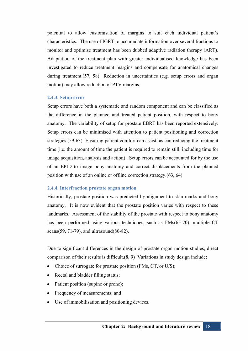
Figure 2.3 Example of fiducial marker used within this thesis (0.9 x 3.0
mm CIVCO Acculoc).
25
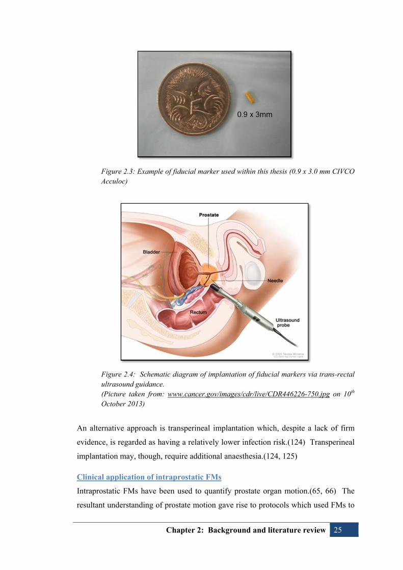
Figure 2.4 Schematic diagram of implantation of fiducial markers via
trans-rectal ultrasound guidance.
25
Figure 2.5 The first linear accelerator modified for kV cone beam
computed tomography.
31
Figure 2.6 Illustration of Varian OBI full-fan and half-fan geometries. 32
Figure 2.7 Example measurements. 44
Figure 3.1 Example of anterior and lateral DRRs used for fiducial marker
(FM) match whereby the field-of-view was defined to enhance
FM visualisation by excluding overlying bony anatomy (arrows
denote FM position).
60
Figure 3.2 Example Bland-Altman plot of interobserver agreement
(observer 1 compared with observer 2) in the (a) superior-
67

List of Figures xii
inferior, (b) left-right, and (c) anterior-posterior directions.
Figure 4.1 Example of a good quality CBCT, demonstrating adequate
visualisation of the soft-tissue anatomy in the (a) transverse; (b)
coronal; and (c) sagittal planes. One of the fiducial markers can
be seen in (a).
77
Figure 4.2 Example of artefacts seen in the CBCTs. Distortion of the soft-
tissue anatomy and FMs is caused by moving gas in the rectum.
The posterior border of the prostate is poorly defined due to the
artefact.
78
Figure 4.3 Modified Bland-Altman plots demonstrating the 95 % limits of
agreement with the mean (LoAMean) for multiple observers
aligning to fiducial markers (CBCTFM) in the SI, LR and AP
planes (a, c, and e respectively). The plots for alignment to
soft-tissue (CBCTST) are shown in the SI, LR and AP planes (b,
d, and f respectively).
79
Figure 5.1 (a) Planar image of FMs; (b) axial slice of CBCT
demonstrating distortion of FM. The FM is distorted in the
CBCT due to motion during the relatively longer image
acquisition with respect to planar imaging.
90
Figure 5.2 Reference CT for Patient 7 – note asymmetric nature of prostate
(red contour), extending posteriorly adjacent to right side of the
rectum (brown contour).
93
Figure 5.3 Reference CT for Patient 10. An axial slice is shown on the left
and sagittal slice on the right. Previous history of TURP can be
seen to negatively impact visualisation of the boundary between
the prostate and bladder.
94

Statement of original authorship xiii
Statement of original authorship
The work contained in this thesis has not been previously submitted to meet
requirements for an award at this or any other higher education institution. To the
best of my knowledge and belief, the thesis contains no material previously
published or written by another person except where due reference is made.
Timothy Deegan
Signature: QUT Verified Signature
Date: 26th February 2015


Acknowledgements xv
Acknowledgements
I would like to thank all those who have supported me throughout this project.
This thesis could not have been completed without the generous assistance of my
supervisors, Dr Andrew Fielding, Dr Rebecca Owen, and Dr Tanya Holt. Each has
been of great help with their insight, support and advice.
The support from my workplace, Radiation Oncology Mater Centre (ROMC), has
also been significant. I cannot imagine completing this project without the dedicated
research time available through the Research Radiation Therapist role at ROMC,
supported by the Princess Alexandra Hospital Trust Fund. I would like to thank my
colleagues for always striving to improve our practice and for their assistance in
collecting the images required for this project. Of particular assistance were my co-
authors Matthew Parfitt, Alicia Coates, Jennifer Biggs and Lisa Roberts. The
support and motivation provided by Cathy Hargrave and Fiona Harden has also been
greatly appreciated.
Financial support from the Medical Radiation Technologists Board of Queensland
(MRTBQ) and the Queensland Health Allied Health Thesis Assistance Scheme
(AHTAS) were also invaluable. Support from these bodies was extremely important
in providing the resources and time necessary for completion of this thesis.
Finally, I owe a tremendous debt of gratitude to my family. The understanding,
generosity, and patience of my wife and daughters has been limitless. I cannot thank
them enough for the support and encouragement they have continued to provide.


List of abbreviations xvii
List of abbreviations
Σ Systematic error
σ Random error
3DCRT Three-dimensional conformal radiation therapy
AAPM American Association of Medical Physicists
AP Anterior-posterior
a-Si Amorphous Silicon
BEV Beams-eye-view
CBCT Cone beam computed tomography
CI Confidence interval
CT Computed tomography
CTV Clinical target volume
DRR Digitally reconstructed radiograph
DVH Dose-volume histogram
EBRT External beam radiation therapy
EORTC European Organisation for Research and Treatment of Cancer
EPID Electronic portal imaging device
FBCT Fan beam computed tomography
FMs Fiducial markers
FoV Field-of-view
GI Gastrointestinal
GTV Gross tumour volume
GU Genitourinary
Gy Gray
ICC Intraclass correlation coefficient
ICRU International Commission on Radiation Units and Measurements
IGRT Image-guided radiation therapy
IMRT Intensity modulated radiation therapy
ITV Internal target volume
kV Kilovoltage
LoA Limits of agreement
LR Left-right

List of abbreviations xviii
MBS Medicare Benefits Schedule
MSAC Medical Services Advisory Council
MLC Multi-leaf collimator
mm Millimetre
MRC Medical Research Council
MRI Magnetic resonance imaging
MV Megavoltage
OARs Organs-at-risk
OBI On-board imager
Obs1 Observer 1
Obs2 Observer 2
Obs3 Observer 3
OnL Online observer
PRV Planning organ-at-risk volume
PSA Prostate-specific antigen
PTV Planning target volume
RCT Randomised controlled trial
ROMC Radiation Oncology Mater Centre
RTOG Radiation Therapy Oncology Group
RTs Radiation therapists
SD Standard deviation
SI Superior-inferior
Sim Simulation
TPS Treatment planning system
TROG Trans-Tasman Radiation Oncology Group
TRUS Trans-rectal ultrasound
TURP Transurethral resection of the prostate
U/S Ultrasound
UTI Urinary tract infection
VOI Volume of interest
XVI X-ray Volume Imaging

Chapter 1: Introduction 1
Chapter 1: Introduction
1.1. Chapter introduction
Over the past few decades, external beam radiation therapy (EBRT) for prostate
cancer has undergone significant advances. Ongoing improvements in EBRT
planning and delivery have allowed treatments to more closely conform to the
targeted prostate and also minimise radiation dose to nearby healthy organs. The
ability to “escalate” radiation dose delivery to the prostate has subsequently resulted
in improved treatment outcomes(1-5), yet also increases the risk of treatment-related
toxicity.(1, 6) Safe, effective EBRT for prostate cancer must balance the competing
interests of achieving maximal tumour dose while also limiting dose to the adjacent
normal tissue, such as the rectum and bladder.
Several new technologies have significantly influenced EBRT practice over the past
few decades. These new technologies have included computed tomography (CT),
three-dimensional planning, multi-leaf collimators (MLCs), electronic portal
imaging devices (EPIDs), and more recently in-room volumetric imaging. They
have resulted in an improved ability to individualise radiation dose delivery by
allowing more accurate shaping of the radiation beam along with the ability to
visualise internal patient anatomy before and during treatment delivery. The use of
these new technologies has given rise to the concepts of intensity-modulated
radiation therapy (IMRT) and image-guided radiation therapy (IGRT).
As with any other therapeutic agent, the greatest challenge for radiation therapy is to
achieve maximum chance of cure with the least morbidity. Therefore, considerable
effort has focussed on utilising new technology to reduce treatment-related toxicity
while achieving higher tumour doses, for example using IMRT. IMRT provides
steep dose gradients and a high degree of conformality around the target which has
improved the ability to avoid normal tissue and has subsequently decreased toxicity
with respect to conventional radiation therapy.(7) The precise nature of IMRT may
increase the potential for underdose of the targeted prostate as steep dose gradients
and tight safety margins increase the risk of geographic miss.

Chapter 1: Introduction 2
Parallel to advances from IMRT, prostate radiation therapy has benefitted from a
greater understanding of organ motion and the integration of IGRT technology with
treatment units. It is well established that the prostate is mobile within the pelvis
relative to bony anatomy and the position of the prostate relative to the rectum and
bladder can also vary.(8, 9) Treatment localisation has subsequently evolved from
simple alignment of bony anatomy to more advanced tracking of the prostate using
surrogates, such as implanted fiducial markers (FMs)(10-12), or direct visualisation
of the gland with volumetric imaging, such as CT(13).
As IGRT has been introduced into clinical practice, the role of radiation therapists
(RTs) has undergone dramatic change.(14) RTs have become increasingly
responsible for autonomous provision of IGRT, often requiring complex decision-
making within a limited time. There have been numerous changes in the frequency,
type, quality, review, and actioning of verification imaging. There has been a
significant shift from infrequent (e.g. weekly) imaging to daily verification.(15) This
has been largely facilitated by the replacement of film-based verification with EPIDs
which allow immediate image review. Electronic imaging has also improved image
quality as tools have become available to manipulate images. Further image quality
improvements have been provided by integration of kilovoltage (kV) systems. The
ability to remotely correct treatment couch position has also streamlined the online
nature of IGRT. Daily pre-treatment verification of prostate position using planar
imaging with implanted FMs is now recommended as standard practice.(16)
More recently, volumetric imaging has emerged as an alternative method of prostate
IGRT.(13) Volumetric imaging is a particularly attractive form of IGRT since the
visualisation of soft-tissue, including the prostate, may offer the opportunity to
forego surrogates such as FMs. The role of soft-tissue alignment with cone beam CT
(CBCT) is, though, largely unproven.(16) In light of the rapid changes in
technology and clinical practice, it is important to evaluate and compare IGRT
methods in order to determine the most appropriate form of guidance and offer an
evidence-based IGRT service.

Chapter 1: Introduction 3
1.2. Thesis objectives
1.2.1 Motivation
The commencement of this study coincided with the acquisition of new linear
accelerators (linacs) with integrated kV imaging at Radiation Oncology Mater Centre
(ROMC). The capabilities of the new hardware provided the impetus to investigate
new IGRT solutions for prostate EBRT. Until that time, ROMC had limited IGRT
capability; the new linacs replaced two units which had no electronic imaging
capability, instead relying on film-based verification (see Figure 1.1). A further two
linacs within the department incorporated ion-chamber EPIDs. These ion-chamber
EPIDs provided limited IGRT capacity due to poor image quality and limited spatial
resolution. An example of anterior and lateral orthogonal images acquired with the
ion-chamber EPIDs for prostate localisation is shown in Figure 1.2.
Figure 1.1 Photographs of (a) de-commissioned Varian 800c, and (b) replacement 21iX linear accelerators. The superseded model had no portal imaging capability while the new model has an integrated On-Board Imager (OBI) (Varian Medical Systems, Palo Alto, CA, USA) with planar and volumetric kV imaging capability.

Chapter 1: Introduction 4
Figure 1.2 Example of megavoltage portal images taken using ion-chamber EPID, circa 2007. Images obtained, with permission, from Radiation Oncology Mater Centre.
The availability of modern, integrated IGRT hardware resulted in the introduction of
FM-based IGRT for prostate EBRT. While new to ROMC, FMs were becoming the
gold-standard for prostate IGRT nationally and internationally. Figure 1.3 represents
an example of anterior and lateral orthogonal planar kV images with FMs implanted
in the prostate.
Figure 1.3 Example of anterior and lateral planar kilovoltage images with three fiducial markers inserted in the prostate.
Several factors can complicate the provision of FM-based IGRT. There are
considerable costs associated with providing the gold markers and the insertion
procedure. In some cases, patients are unwilling to undergo implantation and others

Chapter 1: Introduction 5
are ineligible, for example due to anticoagulant dependence. There is also a risk of
infection from the trans-rectal insertion procedure.(17-19) . Therefore, a cohort of
patients is unable to benefit from FM-based IGRT, and an alternative method of
correcting for prostate motion is required.
The availability of CBCT at ROMC provided the potential for image-guidance based
on visualisation of soft-tissue prostate, without the use of FM surrogates.
Volumetric imaging may also be favoured due to the ability to visualise adjacent
normal tissue such as the rectum and bladder. An example of a CBCT image of the
prostate can be seen in Figure 1.4.
Figure 1.4 Example of kilovoltage cone beam CT image of the male pelvis (note fiducial markers present).
The chief motivation of this research thesis is to compare the planar and volumetric
imaging methods in terms of localisation agreement and also interobserver
variability. This will ultimately inform the appropriate use of prostate IGRT within
our department and ensure the newly acquired hardware is utilised in a safe and
efficient manner. Therefore we have compared localisation of the prostate using two
methods of IGRT: planar kV imaging with FMs; and soft-tissue alignment with kV
CBCT. An important consideration in this comparison is to ensure RTs are able to

Chapter 1: Introduction 6
confidently and consistently perform prostate localisation. Ultimately, the goal of
this investigation is to ensure the IGRT method for prostate EBRT at ROMC is
accurate and reproducible, and provides high-quality treatment for all prostate EBRT
patients, with or without the use of intraprostatic FMs.
1.2.2. Research aims
The aim of this thesis is to investigate whether soft-tissue prostate alignment with
CBCT provides an equivalent means of IGRT compared with the use of planar kV
imaging utilising FMs. In order to effectively compare the planar and volumetric
IGRT methods, two main assessments should be made(20):
a) The repeatability of each of the methods; and
b) Direct comparison of the localisation accuracy from each method.
Therefore, the aims of the research are to:
1. Compare the isocentre localisation results from soft-tissue alignment using
CBCT with the localisation from alignment to FMs (Method comparison);
2. Determine the consistency of RTs aligning to FMs on planar kV imaging
(Interobserver agreement)
3. Determine the consistency of RTs aligning to soft-tissue on volumetric kV
CBCT imaging (Interobserver agreement)
1.3. Thesis outline
This thesis is structured as a Masters by Publication, a presentation of related
published works. Chapter 2 discusses the relevant literature, examining some of the
rapid advances in prostate radiation therapy, and providing a background for prostate
IGRT. Chapter 2 also presents methodological and statistical considerations for the
published articles.
Chapter 3, “Interobserver variability of radiation therapists aligning to fiducial
markers for prostate radiation therapy”, examines the ability of RTs to consistently
align FMs on planar imaging. Chapter 4, “Assessment of cone beam CT registration
for prostate radiation therapy: fiducial marker and soft-tissue methods”, examines
the ability of RTs to consistently align to soft-tissue on CBCT. It also compares the
localisation position obtained from soft-tissue and FMs on CBCT.

Chapter 1: Introduction 7
The published articles which constitute Chapters 3 and 4 have received minor
formatting changes for consistency with the rest of the thesis. The references from
each article have been incorporated into the single reference list at the end of the
thesis. Numbering of headings, tables and figures has been altered to reflect the
thesis presentation. The figures and tables have been incorporated into the text.
Chapter 5 synthesises the main findings which link the manuscripts. It discusses the
critical issues encountered during the preparation of this thesis and looks to the
future directions relevant to this research. Chapter 6 summarises the conclusions
from the investigation.
1.4. Publications
This thesis is presented as a Masters by Publication. There are two peer-reviewed
articles which constitute the body of work. There have also been three relevant
conference presentations from this study: two oral presentations and an electronic
poster.
1.4.1. Journal articles
Deegan T, Owen R, Holt T, Roberts L, Biggs J, McCarthy A, Parfitt M,
Fielding A. Interobserver variability of radiation therapists aligning to
fiducial markers for prostate radiation therapy. J Med Imaging Radiat Oncol
2013; 57(4):519–23.
Deegan T, Owen R, Holt T, Fielding A, Biggs J, Parfitt M, McCarthy A,
Roberts L. Assessment of cone beam CT registration for prostate radiation
therapy: fiducial marker and soft-tissue methods. J Med Imaging Radiat
Oncol, 2015; 59(1):91-98.
1.4.2. Conference presentations
Oral presentation: “Radiation Therapist observer variability in the
assessment of kilovoltage images for prostate radiation therapy”, Annual
Scientific Meeting of Medical Imaging and Radiation Therapy (ASMMIRT),
Adelaide, April 2011;

Chapter 1: Introduction 8
Oral presentation: “Radiation Therapist observer variability in the
assessment of cone beam CTs for prostate radiation therapy”, North
Queensland Multi-Modality Conference, Townsville, August 2011;
Electronic poster: “An assessment of cone beam CT soft-tissue-based
localisation for prostate radiation therapy”, 12th International Conference on
Electronic Patient Imaging (EPI2k12), Sydney, March 2012.

Chapter 2: Background and literature review 9
Chapter 2: Background and literature review 2.1. Chapter introduction
Radiation therapy has been the subject of intense research and development over the
past few decades. Technological advances have resulted in significant
improvements in treatment design, delivery and verification, particularly in the field
of prostate radiation therapy. The complexity of prostate radiation therapy has
increased rapidly as treatments have increasingly aimed to maximise tumour dose
and minimise unwanted dose to normal tissue. Advances in IGRT have been at the
centre of this increasing complexity. In only a few years, IGRT technology has
evolved from poor quality film, to electronic portal-imaging, to high-resolution
volumetric imaging of soft-tissue with CT at the time of treatment.
Numerous IGRT modalities are available for daily localisation of the prostate. This
thesis compares the localisation using two of the most common image-guidance
techniques, planar kV and CBCT using a cohort of prostate cancer patients. The
examination also assesses the RTs’ interobserver variability with each imaging
modality in order to better understand the most appropriate application of IGRT.
2.2. Prostate anatomy
Situated deep within the male pelvis, the healthy prostate is a walnut-sized gland
located adjacent to the urinary bladder and rectum, see Figure 2.1. The prostate
envelops part of the urethra, a narrow tube which carries urine out of the bladder to
the penis. Part of the male reproductive system, the prostate’s main function is to
secrete a milky white fluid that forms a large portion of seminal fluid which carries
sperm. The proximity of the rectum and urinary bladder, as shown Figure 2.1, is
highly relevant to prostate radiation therapy.
The prostate can be divided into four zones: the peripheral, central, transition, and
anterior fibro-muscular zones. The peripheral zone constitutes the posteriolateral
aspect of the prostate, and comprises the majority of prostatic glandular tissue.(21,
22) The zonal boundaries are largely indistinct in young men, but significant

Chapter 2: Background and literature review 10
changes occur as men age and benign prostatic hyperplasia causes the transition zone
to enlarge and dominate the prostate.(23)
Figure 2.1: Sagittal view of male pelvic anatomy, demonstrating the position of the prostate within the pelvis and the proximity with the bladder and rectum. (Picture taken from anatomisty.com/male-anatomy/male-reproductive-organs-2/attachment/male-reproductive-organs-2/ on 10th October 2013)
2.3. External beam radiation therapy for prostate cancer
Prostate cancer accounted for 33 % of newly diagnosed cancers among males in
Australia in 2009.(24) Only non-melanoma skin cancers are more frequently
diagnosed in Australia. In 2010, 19,821 new cases of prostate cancer were
diagnosed in Australia. The incidence of prostate cancer is steadily increasing, with
estimations of 25,310 new prostate cancer cases in 2020 in Australia.(25) The age-
standardised incidence of prostate cancer has increased over time, from 79 new cases
per 100,000 males in 1982 to 194 per 100,000 in 2009.(24) Tremendous advances in
diagnosis and therapy have meant that while prostate cancer incidence has increased,
relative survival has markedly improved from 58.2 % in the period between 1982
and 1987 to 92.0 % in 2006-10.(26)

Chapter 2: Background and literature review 11
Active treatment options for localised prostate cancer include:
Surgery;
Radiation therapy;
o External bean radiation therapy (EBRT);
o Brachytherapy;
Hormonal therapy; and
Active surveillance.
The choice of treatment modality is based on several factors, such as initial prostate-
specific antigen (PSA) level, the clinical stage of disease, and Gleason score.
Consideration is also given to baseline urinary function, comorbidities and patient
age. While brachytherapy and active surveillance have become more prominent
options in recent times, surgery and EBRT remain the most common forms of
treatment.(27) Although not all patients require therapy, active treatment of prostate
cancer has been shown to offer a survival advantage.(28)
Radiation therapy is one of the primary forms of treatment for prostate cancer. The
main principle of radiation therapy is to deliver sufficient dose of radiation to
achieve tumour control while minimising dose to the neighbouring normal tissues, or
organs-at risk (OARs). EBRT is a widely established treatment option for prostate
cancer, particularly for intermediate- and high-risk disease. Considerable effort to
improve outcomes from prostate EBRT has resulted in significant advances over
recent decades. In the 1990s, conventional prostate radiation therapy was associated
with significant rates of local relapse, leading to a high risk of distant metastases and
relatively poor survival.(2, 4, 29) Improvements in prostate EBRT have focussed on
increasing control rates while simultaneously decreasing treatment-related toxicity.
2.3.1. Technical advances and dose-escalation in prostate EBRT
In the 1980s and 1990s, radiation therapy was revolutionised by the introduction of
technological advances including CT scanning(30), MLCs driven by computerised
algorithms(31), as well as new computerised treatment planning systems which
utilised features such as beams-eye-views (BEVs) digitally reconstructed
radiographs (DRRs) and dose-volume histograms (DVHs)(32-34).

Chapter 2: Background and literature review 12
Until such advances, conventional prostate EBRT was limited to two-dimensional
design. Radiation therapy treatment plans typically consisted of few beams arranged
in opposed pairs or four-field boxes. The treatment beams were often unshaped
rectangular treatment portals which inevitably included large volumes of normal
tissue as well as the targeted prostate. Such treatment resulted in significant risk of
late side-effects, such as rectal bleeding, therefore limiting therapeutic doses to 60-
70 Gy.(29, 35) Technological advances in the 1990s saw the introduction of three-
dimensional conformal radiation therapy (3DCRT), which utilised CT-based
planning and conformal shielding.(34, 36) Introduction of 3DCRT resulted in
improved delineation of the prostate using CT, more accurate dose calculations and
increased conformality of dose delivery. These factors combined to improve
avoidance of OARs in treatment design.
Several randomised controlled trials (RCTs)(6, 29, 37) and historical series(2, 38)
have subsequently evaluated dose-escalated prostate EBRT using photons.
Interpretation of many dose-escalation studies is complicated by changes in
diagnosis, staging, and therapy over the period since initial accrual, yet their results
are strongly in favour of the advantage of dose-escalation. The results of three major
randomised dose-escalation trials are summarised in Table 2.1. Increasing the
prescribed dose has been shown to increase biochemical control(1, 39, 40), reduce
distant metastases(2, 4), and improve cause-specific survival(4). No direct evidence
of improved overall survival has, as yet, been obtained from RCTs studies.(40)
Epidemiological data has, though, shown that prostate cancer survival continues to
improve.(26)
Table 2.1: Summary of prostate EBRT dose-escalation RCTs
Trial Conventional
dose (n) Escalated dose (n)
Median FU (months)
Significant improvements
(p ≤ 0.05)
No difference (p > 0.2)
M.D. Anderson (39)
70 Gy (150)
78 Gy (151)
104 BCF CF
OS
MRC RT01 (41)
64 Gy (421)
74 Gy (422)
120 BCF OS
Dutch group (40)
68 Gy (331)
78 Gy (333)
110 BCF LF
CF DM PCD OS
n, number of patients; BCF, biochemical or clinical failure; CF, clinical failure; LF, local failure; OS, overall survival; DM, distant metastasis; PCD, prostate cancer death

Chapter 2: Background and literature review 13
A meta-analysis of dose-escalation RCTs concluded that dose-escalation should be
offered to all patients undergoing definitive prostate EBRT regardless of their
disease risk status in order to reduce the risk of recurrence.(42)
2.3.2. Prostate radiation therapy-related toxicity
While the above studies confirmed that dose-escalation can improve prostate disease
control, they also demonstrated that raising the prescribed dose caused increased
toxicity, especially to the rectum. Dose-escalation has been shown to significantly
increase the likelihood of gastrointestinal (GI) toxicity.(1, 39, 43) Retrospective
analysis indicated that GI toxicity could be reduced by limiting the amount of rectum
irradiated.(37) Conversely, no dose-escalation trial has demonstrated statistically
significant increases in genitourinary (GU) toxicity with increasing dose.(1, 37, 39,
43, 44) The Dutch trial suggested it is likely that GU toxicity is under-reported since
GU symptoms require particularly long-term follow-up.
While it can be generalised that higher prescription dose will by definition equate to
increased toxicity, there are measures to reduce the risk.(40) In order to facilitate
dose-escalation, it has become obvious that limiting the amount of normal tissues
included in the treatment volume is required. IMRT has emerged as a useful means
to this end.
Dose-escalation studies have resulted in a better understanding of the dose-response
of the prostate and OARs. Toxicity data has informed appropriate dose-volume
constraints to minimise side-effects.(45) It is believed that further dose-escalation is
required to achieve continued improvements in control rates, either by prescribing
above 80 Gy(42, 46) or by hypofractionating dose in fewer fractions(47). In order to
continue dose-escalation, techniques which improve rectum sparing, such as IMRT,
have been required.(37)
As its name suggests, IMRT essentially splits the treatment field into numerous
“beamlets” which can each have their own intensity of radiation dose. This allows
the overall treatment field to consist of areas of high and low intensity to better
control the dose delivered. The modulation of dose within treatment fields presents
almost limitless ability to sculpt radiation dose around targets and OARs. The

Chapter 2: Background and literature review 14
widespread introduction of IMRT has resulted in more complex field shaping and
greater conformality of dose delivery to the targeted prostate. Importantly, this has
also led to improved sparing of the OARs.
IMRT enables steep dose-gradients between the target and adjacent OARs. In the
case of prostate IMRT, this is intended to achieve high target doses with improved
sparing of the rectum and bladder. IMRT is often used to achieve higher target doses
and/or reduced OAR dose compared with 3DCRT.(7, 48-50) IMRT is generally
unable to reduce the risk or severity of GU toxicity, most likely because the bladder
neck and inferior portion of the bladder trigone remains in the high-dose portion of
the planning target volume (PTV).(7, 49, 50)
2.3.3. The risk of geographic miss in prostate EBRT
The risk of geographic miss and subsequent systematic underdose of the target has
been increased with the use of IMRT, due to the associated steep dose gradients and,
in many cases, tight PTV margins. Compounding this risk is the uncertainty due to
prostate organ motion secondary to variable filling of the rectum and bladder
(discussed in detail in following section). Even in the pre-IMRT era, the risk of
geographic miss was shown to be high by de Crevoisier et al. and Heemsbergen et
al.(51, 52) A reduction in biochemical control of about 30 % at five years was found
by de Crevoisier et al. when the rectum was distended at simulation compared to the
time of treatment.(51) The results suggest that the rectum was often empty during
treatment due to treatment-related effects, such as diarrhoea. Therefore, a distended
rectum at simulation was not representative of the anatomy over the course of
treatment. Without IGRT, these errors could not be corrected and the prostate was
likely to shift posteriorly, outside the high-dose region. In order to minimise the risk
of geographic miss, it is important to understand treatment-related uncertainties and
perform accurate target localisation prior to treatment delivery, for instance using
IGRT.

Chapter 2: Background and literature review 15
2.4. Uncertainties in prostate EBRT
2.4.1. The nature of systematic and random errors
Inevitably there are several types of errors or uncertainties involved in the planning
and delivery of EBRT. Such errors can generally be categorised into systematic (Σ)
or random (σ) errors. Systematic errors can be broadly regarded as treatment
preparation errors, affecting all fractions. Systematic errors have the effect of
shifting the overall dose distribution. Random errors are those broadly regarded as
treatment execution errors, affecting each fraction individually. The effect of
random errors is different to that of systematic, as they act to blur the dose
distribution.
Types of uncertainty within EBRT include:
Delineation uncertainties: e.g. due to inter- and intra-observer variations, affected
by image quality and modality;
Phantom-transfer errors: systematic uncertainties from the transfer of information
between systems such as from the CT to the planning system, to the record-and-
verify system, to the linac;
Patient setup variability: e.g. due to the variable relationship of external setup
marks (such as tattoos) and internal anatomy;
Interfraction organ motion: e.g. displacement, including translation and rotation,
of the internal organs between fractions;
Intrafraction motion: e.g. organ motion from patient movement, respiratory
motion, cardiac motion or peristalsis;
Anatomic changes: e.g. deformation due, for example, to tumour response
growth or oedema;
Image-guidance errors: e.g. from finite resolution of IGRT system, residual
couch correction errors;
Delivery uncertainties: e.g. dose calculation uncertainties, multi-leaf collimator
(MLC) motion uncertainty.
IGRT aims to reduce, but cannot eliminate, the errors associated with EBRT. IGRT
is most effective in reducing setup and organ motion errors. A level of residual
uncertainty will always remain after attempts to correct known errors. For instance,

Chapter 2: Background and literature review 16
IGRT cannot eliminate delineation errors. Any limitations inherent in the IGRT
method will also produce additional uncertainties (e.g. intra- and interobserver
variation as well as the latency between image acquisition and treatment). The
presence of intrafraction motion or target deformation is difficult to correct with
current technology. Additionally, the process of correcting patient position by
adjustment of the treatment couch will have some level of inaccuracy. Subsequently,
the use of a safety margin is required to account for these errors.
2.4.2. Volumes and associated margins
The International Commission on Radiation Units and Measurements (ICRU)
established standard terminology for the creation of margins over twenty years ago
(53), and continues to refine them as technology advances(54, 55). ICRU definitions
of the volumes used in margin creation can be summarised as:
Gross tumour volume (GTV): the primary tumour volume. Can be defined on a
variety of imaging modalities, including pre-operative series.
Clinical target volume (CTV): includes GTV and possible microscopic disease
(subclinical involvement). The CTV should include a margin for delineation
error in the definition of the GTV.
Internal target volume (ITV): a component of the PTV, this additional margin is
required to account for potential variations in CTV position, shape and/or size.
This includes inter- and intrafraction variation. This internal margin includes an
expansion to account for variations due to organ motion from, for example,
respiration or peristalsis. It should be noted that this volume is not defined
explicitly, but is incorporated in next stage.
Planning target volume (PTV): consists of the above GTV, CTV and ITV. Also
includes the setup margin which is intended to account for geometric errors
between planning and treatment. Essentially, the PTV is a geometric construct
which serves to ensure that an adequate dose will be delivered to all parts of the
CTV (within a clinically acceptable probability).
Planning organ-at-Risk volume (PRV): margin around OARs to account for set-
up uncertainty and changes in their position, shape and size. The proximity of
OARs to the targeted tissue can have an influence on PTV design, whereby target
margins are minimised to avoid overlap with the OAR.
Chapter 2: Background and literature review 17
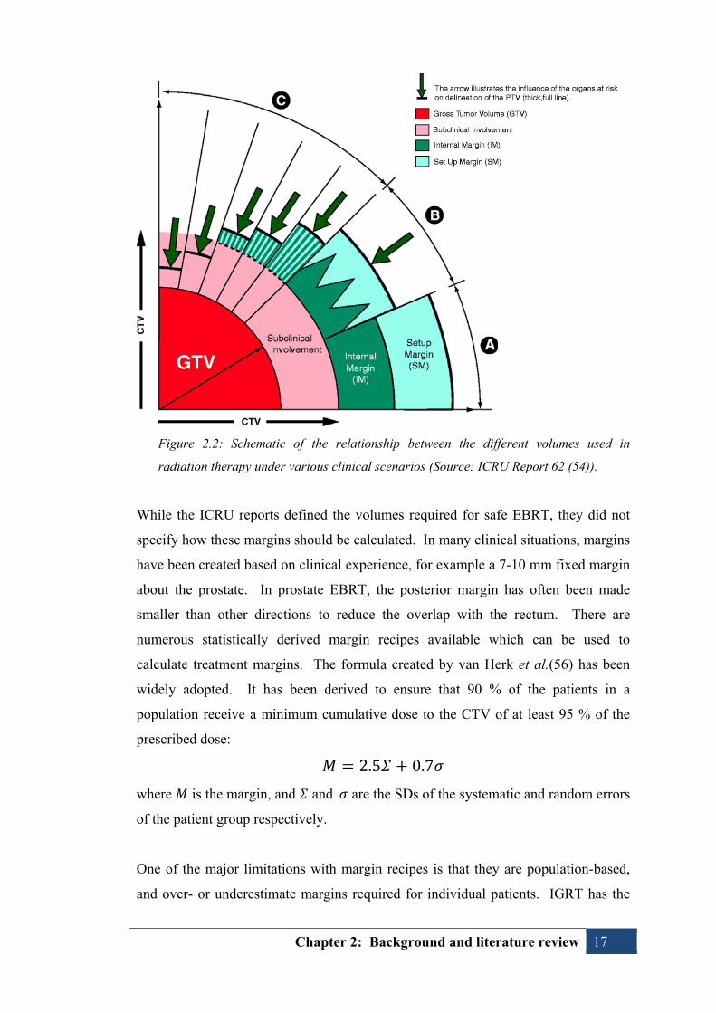
Figure 2.2: Schematic of the relationship between the different volumes used in
radiation therapy under various clinical scenarios (Source: ICRU Report 62 (54)).
While the ICRU reports defined the volumes required for safe EBRT, they did not
specify how these margins should be calculated. In many clinical situations, margins
have been created based on clinical experience, for example a 7-10 mm fixed margin
about the prostate. In prostate EBRT, the posterior margin has often been made
smaller than other directions to reduce the overlap with the rectum. There are
numerous statistically derived margin recipes available which can be used to
calculate treatment margins. The formula created by van Herk et al.(56) has been
widely adopted. It has been derived to ensure that 90 % of the patients in a
population receive a minimum cumulative dose to the CTV of at least 95 % of the
prescribed dose:
2.5 0.7
where is the margin, and and are the SDs of the systematic and random errors
of the patient group respectively.
One of the major limitations with margin recipes is that they are population-based,
and over- or underestimate margins required for individual patients. IGRT has the
Chapter 2: Background and literature review 18
potential to allow customisation of margins to suit each individual patient’s
characteristics. The use of IGRT to accumulate information over several fractions to
monitor and optimise treatment has been dubbed adaptive radiation therapy (ART).
Adaptation of the treatment plan with greater individualised knowledge has been
investigated to reduce treatment margins and compensate for anatomical changes
during treatment.(57, 58) Reduction in uncertainties (e.g. setup errors and organ
motion) may allow reduction of PTV margins.
2.4.3. Setup error
Setup errors have both a systematic and random component and can be classified as
the difference in the planned and treated patient position, with respect to bony
anatomy. The variability of setup for prostate EBRT has been reported extensively.
Setup errors can be minimised with attention to patient positioning and correction
strategies.(59-63) Ensuring patient comfort can assist, as can reducing the treatment
time (i.e. the amount of time the patient is required to remain still, including time for
image acquisition, analysis and action). Setup errors can be accounted for by the use
of an EPID to image bony anatomy and correct displacements from the planned
position with use of an online or offline correction strategy.(63, 64)
2.4.4. Interfraction prostate organ motion
Historically, prostate position was predicted by alignment to skin marks and bony
anatomy. It is now evident that the prostate position varies with respect to these
landmarks. Assessment of the stability of the prostate with respect to bony anatomy
has been performed using various techniques, such as FMs(65-70), multiple CT
scans(59, 71-79), and ultrasound(80-82).
Due to significant differences in the design of prostate organ motion studies, direct
comparison of their results is difficult.(8, 9) Variations in study design include:
Choice of surrogate for prostate position (FMs, CT, or U/S);
Rectal and bladder filling status;
Patient position (supine or prone);
Frequency of measurements; and
Use of immobilisation and positioning devices.

Chapter 2: Background and literature review 19
Many of the prostate motion studies involved interventions at simulation which were
not repeated at subsequent sessions, such as use of enema or introduction of contrast.
Regardless of methods, these studies have clearly demonstrated that skin marks and
bony anatomy are poor surrogates of prostate position. Table 2.2 is a summary of
selected interfraction prostate motion studies.
Table 2.2: Summary of literature reporting one standard deviation (SD) interfraction
prostate displacement relative to bony anatomy
Variability of prostate position between treatment fractions has been shown to be
most pronounced in the anterior-posterior (AP) and superior-inferior (SI) directions,
while the prostate is most stable in the left-right (LR) direction.(67, 75, 77, 83)
Quantification of motion has indicated that variable prostate positioning is highly
correlated with differences in rectal size and, to a lesser extent, bladder filling.(59,
65, 71-75, 77, 84, 85) Several studies of prostate motion have concluded that daily
localisation of the prostate is required to correct for the large, unpredictable prostate
Study Pts Modality Surrogate 1 SD displacement
(mm) SI LR AP
van Herk, 1995(59)
11 Repeat CTs: Simulation
& weeks 2, 4, 6 Contours 2.4 1.3 3.8
Roeske, 1995(72)
10 Weekly CT Contours 3.2 0.7 3.9
Althof, 1996(67)
9 Planar kV (simulator) 125I seeds 1.7 0.8 1.5
Rudat, 1996(74)
28 CT (single 8mm axial
slice) N/A 1.9 3.7
Melian, 1997(75)
13 CT 3.1 1.2 4.0
Vigneault, 1997(68)
11 EPID Single apical FM 3.6 1.9 3.5
Antolak, 1998(76)
17 Repeat CTs: Simulation
& weeks 2, 4, 6 3.6 0.9 4.1
Stroom, 1999(78)
15 Repeat CTs: Simulation
& weeks 2, 4, 6
Contoured CTV on each CT (Chamfer matched to bones)
2.8 0.6 2.8
15 Repeat CTs: Simulation
& weeks 2, 4, 6
Contoured CTV on each CT (Chamfer matched to bones)
1.7 0.5 2.1
Zelefsky, 1999(77)
50 Repeat CTs: Simulation, day 1, week 4, and last
week
Contoured CTV on each CT (Chamfer matched to bones)
3.3 0.8 2.9
Wu, 2001(69)
13 EPID FMs 2.1 N/A 2.3
Frank, 2008(79)
15 Simulation CT & 3/week
CT (CT-on-rails) Contours 2.9 0.9 4.1

Chapter 2: Background and literature review 20
motion using methods such as implanted FMs as a surrogate of prostate position.(65,
66)
2.4.5. Intrafraction prostate organ motion
Prostate motion during the treatment session (intrafraction motion) has been
quantified by various means, including imaging FMs before and after treatment(86-
90), as well as use of cine-MRI(91-93), U/S(94), and electromagnetic
transponders(95-97). While the prostate can be very stable during a treatment
session, there are two main types of motion possible.(95-97) The prostate has been
observed to slowly drift in position, possibly due to relaxation of the pelvic muscles.
Otherwise, transitory motion, associated with peristaltic motion, has been described
where the prostate shifts a large distance (often >10 mm) but returns close to its
original position within a short time period.(97) Similar to interfraction motion,
shifts are most evident in the SI and AP directions. Intrafraction prostate motion has
been shown to be correlated with rectal motion, and can exceed 10 mm.(91, 92)
Less intrafraction motion was found compared with interfraction variations.(93)
It has been generalised that intrafraction motion is inconsequential compared with
interfraction displacement.(92) Yet, as correction for interfraction motion is readily
achieved, the effect of intrafraction prostate motion has become increasingly
relevant. The significance of intrafraction motion varies according to the nature of
the movement. For conventionally fractionated treatments, short transitory motions
are likely to have less dosimetric impact than a persistent drift. The biggest impact
of intrafraction motion is the unlikely event that short, transitory motion coincides
with the timing of pre-treatment imaging. Intrafraction monitoring has highlighted
the benefit of reducing the treatment session time and commencing treatment as soon
as possible after initial positioning.(97, 98) It is important to minimise the time
required for image acquisition and interpretation to reduce the likelihood of prostate
motion away from the imaged position.
2.4.6. Prostate deformation and rotation
As well as shifting within the pelvis, the prostate is known to change size and shape,
and rotate during a course of EBRT. In early investigations of prostate volume
changes, Roeske et al. found that for individual patients, the prostate and seminal
vesicle volume can vary by ±20 % and -50-70 % respectively.(72) Another study by

Chapter 2: Background and literature review 21
Roach et al. found that for individual patients, a 14 % median variation from the
average prostate volume was detected, along with a 28 % average maximum
variation between the largest and smallest prostate volumes.(99) A comparison of
the planning CT and another CT, repeated 2 week later, found the prostate decreased
in volume by 14 % (averaged over all patients). Subsequently, the prostate volume
tended to stabilise.(99)
Deurloo et al. delineated the prostate on multiple repeat CT scans and found that
there were no significant variations in prostate volume during the course of
EBRT.(100) They concluded that deformation was sufficiently small that the
prostate could be considered a solid-organ for the purpose of IGRT. Multiple CTs
were also used by van der Wielen et al. to determine prostate and seminal vesicle
deformation.(101) Variations were measured with respect to intraprostatic FMs.
They found small prostate deformation (SD < 1 mm), similar to the results of
Deurloo et al.(100) The seminal vesicle deformation, though, was considerably
larger (SD ≤ 3 mm). Nichol et al. examined variations in prostate size and shape
relative to FMs using MRI.(102) They found that the prostate exhibited shape and
volume changes during treatment. The prostate volume was observed to enlarge (by
up to 34 %) on MRIs taken in the first half of EBRT. On MRIs taken in the second
half of treatment, the prostate was found to shrink (by up to 24 %) compared with
the planned volume. The distance between FMs also reduced over the treatment
course.
Changes in prostate rotation have also been investigated. Hoogeman et al.
performed several repeat CTs to quantify prostate motion, including rotation.(103)
Large variations in the size of the rectum at planning were found to cause large
systematic errors in prostate rotation about the LR axis (1 SD = 5.1°). An adaptive
approach, using the planning and four repeat CTs, was able to reduce the rotational
error significantly. Boda-Heggemann et al. measured prostate rotation relative to
FMs.(104) Variations in prostate tilt were correlated with AP displacement of the
prostate, while the degree and angle of the tilt depended on the direction and
magnitude of prostate motion.(104) Posterior prostate motion was observed to cause
a systematic tilt of 1°/mm. Owen et al. measured prostate rotations using two
methods: FMs and the prostate-rectum border as observed using CT-on-rails.(105)

Chapter 2: Background and literature review 22
Prostate rotation was found to be a significant source of error, which was more
accurately measured using CT images.
More recently, investigations have been performed to measure prostate rotation
using implanted electromagnetic transponders.(106) Prostate rotations were found to
be much larger than deformation, with the potential to cause target underdose if not
managed. Despite correction for prostate displacement, 16 % of patients included in
the study would have been underdosed when using a 5.0 mm PTV margin. Amro et
al. found that the dosimetric impact of prostate rotation varies on an individual
patient basis.(106)
2.4.7. Strategies to minimise prostate motion
As outlined above, variations in rectal and/or bladder volume have been shown to
alter the prostate position with the pelvis. A common approach to reducing prostate
organ motion, then, has been to reduce the daily variations of rectal and bladder
filling. Wu et al. postulated that instructing patients to control bladder and rectal
filling may have led to smaller prostate motion than had been observed in other
studies.(69)
Roach et al.(107) and Pickett et al.(108) took the approach of acquiring planning
CTs with a full bladder and empty rectum based on the expectation this would
achieve the most posterior prostate position. Subsequently, they applied relatively
tight posterior margins with larger margins anteriorly to account for motion. No
attempt was made to control rectal filling at treatment, but patients were treated with
a full bladder. A follow-up study to validate the variable margin theory
demonstrated posterior prostate motion was still likely, as well as systematic
variation superior to the planned position.(99)
Additional studies have also demonstrated that attempts to limit rectal variations
have limited success in reducing prostate motion. Kupelian et al. have shown that
prostate motion is still evident despite an empty rectum at simulation.(109) There
are indications that controlling diet can decrease the incidence of rectal gas, and
therefore prostate motion.(110) Conversely, other studies have shown that the use of
agents such as milk of magnesia to promote an empty rectum has little effect in

Chapter 2: Background and literature review 23
limiting inter- or intrafraction prostate motion.(111, 112) Mechanical removal of
bowel gas at the time of treatment has, though, been shown to decrease prostate
motion.(113)
An alternative approach has been to attempt to reproduce a distended rectum using
endorectal balloons in order to minimise variation from the simulated rectal
size.(114) This is intended to reduce prostate motion secondary to variations in
rectal size. Additionally, the rectal balloon has the effect of moving a portion of
rectum away from the prostate, allowing the posterior part of the rectum to be
shielded from the high-dose region.(115)
While it is recognised that prostate motion is more correlated with rectal variation
rather than with differential bladder filling, it is also common to attempt to reproduce
a consistent bladder volume. Many clinical protocols prefer the bladder to be
“comfortably” full during prostate EBRT. This state is probably more difficult to
reproduce than an empty bladder, but it has benefit of shifting a portion of the
bladder and small bowel away from the high-dose treatment region. Therefore, it
could be argued that the desire for a full bladder volume is based on minimising
bladder and small bowel toxicity as much as trying to reduce prostate motion.
2.5. Prostate image-guided radiation therapy (IGRT)
Despite attempts to reduce prostate motion, as outlined above, the prostate is highly
mobile and it is important to identify and correct variations in target location at the
time of treatment delivery. This can be performed using various image-guidance
methods.
2.5.1. Image guided radiation therapy methods
There are numerous IGRT modalities with the potential to more accurately guide
treatment delivery for prostate EBRT. The most common IGRT techniques utilise x-
rays either from the megavoltage (MV) treatment beam or a kV “diagnostic” source.
The optimal IGRT solution for prostate EBRT is unclear, yet it should have certain
attributes, such as accuracy and consistency across multiple operators and clinical
situations.(116, 117) Ideally, the IGRT solution would be minimally invasive, with
low imaging dose and high patient tolerability. It should also be efficient in terms of

Chapter 2: Background and literature review 24
additional workload required, including training and ongoing quality assurance. It
would also be desirable to have an IGRT solution which is transferable to other
treatment sites.
This section concentrates on the two modalities investigated in this thesis:
planar kV imaging (utilising FMs); and
kV CBCT.
2.5.1.1. Planar IGRT using intraprostatic fiducial markers
There can be significant prostate motion relative to bony landmarks. The traditional
use of skin marks and portal imaging based on bony anatomy has been shown to lack
the accuracy required to treat the prostate to therapeutic doses while maintaining
appropriate margins to avoid excessive toxicity. Unfortunately, the prostate lacks
sufficient radiographic contrast with adjacent structures to be visible on planar
radiographic imaging. Therefore, implantation of radio-opaque FMs, acting as a
surrogate of prostate position, has become one of the most widely adopted
techniques for prostate localisation.
The most commonly used FMs for prostate EBRT are small gold seeds
(approximately 0.8 to 1.0 mm diameter and 3.0 to 5.0 mm length). The inert, radio-
opaque nature of gold makes it an ideal substance for implantation. Generally, three
FMs are considered to act as surrogate for the positioning of the solid organ
prostate.(118) Some of the earliest documented uses of implanted markers in the
prostate are from Sandler et al.(119) and Shipley(120).
Implantation of FMs
FMs are typically inserted into the prostate using trans-rectal ultrasound (TRUS)
guidance in a manner similar to that of diagnostic biopsy.(18, 121, 122) Patients are
required to cease anticoagulant medication approximately one week prior to
implantation. Generally, patients are provided with antibiotic prophylaxis prior to
and during the procedure. An enema preceding the implantation is recommended to
empty the bowel in order to improve ultrasound visualisation and also reduce the risk
of infection. The use of anaesthetic, such as nerve block, is not universal, but
depends on local protocols. Generally, three sterilised FMs are triangulated within
the prostate: at the prostate base, apex and mid-gland.(12, 123)
Chapter 2: Background and literature review 25
Figure 2.3: Example of fiducial marker used within this thesis (0.9 x 3.0 mm CIVCO Acculoc)
Figure 2.4: Schematic diagram of implantation of fiducial markers via trans-rectal ultrasound guidance. (Picture taken from: www.cancer.gov/images/cdr/live/CDR446226-750.jpg on 10th October 2013)
An alternative approach is transperineal implantation which, despite a lack of firm
evidence, is regarded as having a relatively lower infection risk.(124) Transperineal
implantation may, though, require additional anaesthesia.(124, 125)
Clinical application of intraprostatic FMs
Intraprostatic FMs have been used to quantify prostate organ motion.(65, 66) The
resultant understanding of prostate motion gave rise to protocols which used FMs to

Chapter 2: Background and literature review 26
correct displacement on a daily basis.(10, 11) Technological innovations in EPID
and treatment couch hardware were important in enabling daily IGRT for prostate
EBRT. The advent of high-resolution amorphous silicon (a-Si) EPIDs resulted in the
ability to image fine diameter FMs with the MV treatment beam.(11, 126) The
ability to remotely adjust the treatment couch also facilitated immediate (on-line)
correction of prostate displacements.(127) One of the chief advantages of FM-based
IGRT is the ease of matching markers on planar imaging.(126) Daily, on-line
correction of prostate motion with FMs, in conjunction with MV or kV planar
imaging, has subsequently been widely implemented.(11, 12, 68, 69, 123, 126, 128-
134)
Daily on-line correction for prostate motion based on FMs is able to account for
interfraction organ motion and patient setup uncertainties (i.e., both systematic and
random error components). It is important to note that residual errors remain due to
factors such as delineation uncertainty, phantom transfer errors, finite resolution of
the imaging system, couch correction uncertainty and intrafraction motion errors.
Therefore, even with a daily on-line correction protocol, a PTV margin is required.
FMs: risks and complications
Insertion of FMs under TRUS-guidance is regarded as safe and well tolerated, yet it
is not without risks and complications.(17-19) Langenhuijsen et al. reported
minimal complication rates despite use of relatively large FMs (1.0 x 7 mm).(18)
Follow-up of 209 men undergoing the TRUS implantation procedure found 6.2 %
had moderate complication from pain and fever, which was resolved with oral
medication. Other reported complications included voiding difficulty (1.9 %),
haematuria for > 3 days (3.8 %), haematospermia (18.5 %), and rectal bleeding (9.1
% cases). Shinohara et al. reported only one of 705 patients implanted with gold
FMs developed a urinary tract infection (UTI) requiring antibiotic treatment.(121)
This assessment required patients to report unexpected or severe complications
following the procedure and therefore may be underestimated.
İğdem et al. found that men undergoing TRUS insertion of FMs reported less pain
than was associated with their biopsy procedure.(17) No major toxicities requiring
intervention were reported. Haematuria, rectal bleeding and fever were reported by

Chapter 2: Background and literature review 27
15 %, 4 % and 2 % of patients respectively. Gill et al. surveyed patients who had
previously undergone TRUS-guided insertion of FMs and found that 32 % of
patients experienced at least one symptom, such as urinary frequency, haematuria,
dysuria, rectal bleeding, and haematospermia.(19) Significantly, three patients
required hospital admission for infectious complications, including a case of Grade 4
sepsis with E. coli resistant to both ciprofloxacin and gentamycin. The survey
results indicated that unless specifically sought, complication rates are probably
underreported, as many of the complications identified in the survey had never been
otherwise reported to the department despite the expectation for patients to do
so.(19)
Berglund et al. reported infection risks following insertion of electromagnetic
transponders.(135) An assessment of 50 patients found five developed infectious
complications, and three required antibiotic treatment for UTI. Two patients
developed significant infectious complications, including one who developed a
prostatic abscess with methicillin-resistant bacteria and subsequently died of an
unrelated lower GI bleed.
There is evidence that infectious complications following TRUS biopsy are
increasing in incidence.(136) Of particular concern is the emergence of infections
complicated by multi-drug resistant Escherichia coli. Patients undergoing TRUS
insertion of FMs may be at particular risk since they have previously been exposed
to quinolone antibiotics during their diagnostic biopsy. They are subsequently at
elevated risk of infection from the resistant bacteria. A further complication with
insertion of FMs is the requirement for patients to cease anti-coagulants
approximately one week prior to the procedure. This results in some patients
becoming ineligible for FMs and subsequently unable to undergo FM-based IGRT.
While the risks associated with TRUS insertion of FMs may be generally regarded as
minimal, it has been shown that significant morbidity can result from the procedure.
Therefore, it is worth investigating alternative IGRT methods which could eliminate
the need for FMs.

Chapter 2: Background and literature review 28
FMs as a prostate surrogate
The underlying premise of using FMs as a surrogate of prostate position is that the
markers represent the position of the prostate over the entire course of treatment.
The accuracy of FMs as a surrogate of prostate motion has been questioned with
respect to the potential for seed migration, as well as their ability to demonstrate
prostate rotation and deformation. It is important, then, that the FMs do not move
appreciably within the prostate and the size and shape of the prostate should be
stable throughout the treatment course.
Numerous investigations have focussed on establishing the appropriateness of FMs
as a surrogate of prostate position by measuring the distance between individual FMs
over time. In a small patient series, Shirato et al. demonstrated significant in-
migration of intraprostatic FMs in five out of six patients, consistent with a mean
rate of volume decrease of 9.3 % in ten days.(137) A number of other studies have
also shown variations in intermarker distances.(69, 126, 128, 138, 139) However,
several other studies have shown that the FMs remain relatively stable over a course
of treatment.(129, 131, 140)
In the most comprehensive assessment of intermarker distances, Kupelian et al.
assessed 56 patients with three intraprostatic FMs (2,037 daily alignments).(141)
Very few markers (2/168) were found to undergo a significant change in relative
position, and the variation was attributed to prostate deformation rather than marker
migration.(141) Kupelian et al. recommended the use of the centre-of-mass of the
three FMs to reduce the uncertainty due to variations of individual markers.(141)
They concluded that FMs are a reliable means of prostate localisation, even in the
presence of prostate deformation.
Another study of inter-marker distances during a course of EBRT by van der Heide
et al. indicated an initial small increase in inter-marker distance followed by a
reduction of about 4 % during treatment (average 0.9 mm change).(132) The authors
speculated that such variations between FMs may be due to oedema at the initiation
of EBRT and then gradual prostate shrinkage as treatment progresses. While small
inter-marker distances were identified, it was suggested that the effect of determining

Chapter 2: Background and literature review 29
the centre-of-mass of the FMs was minor (by a factor of 1/√2). Use of more than
two FMs was recommended to further reduce this uncertainty.
Nichol et al. found that during a course of EBRT, the prostate shrank and changed
shape, i.e. deformed. The distance between FMs also reduced over time.(102) Since
patients only underwent one MRI during the treatment course, the study lacked
sufficient data to map the precise timeline of prostate volume changes. The authors
found that, on rare occasions, patients could undergo large variations in prostate size
and shape which daily imaging of FMs could not detect. It was suggested that soft-
tissue imaging, such as with CBCT, was required to detect and correct such prostate
deformations.(102)
Prostate rotations have been assessed by Owen et al. using FMs and soft-tissue-
guidance with CT-on-rails. Volumetric imaging was shown to determine prostate
rotation more accurately than FMs.(105) The ability of FMs to demonstrate prostate
rotation was affected by the position and proximity of implantation.
In summary, the literature suggests FMs are a good surrogate for the position of the
prostate. In the presence of rotation or deformation of the prostate, FMs are less able
to predict the prostate position. CBCT may be better able to monitor and therefore
correct prostate rotations and deformation than FMs. Soft-tissue visualisation with
CBCT has the benefit of allowing assessment of changes in prostate volume as well
as position.
Economic implications of FMs
There are several financial implications when adopting FMs for IGRT, such as the
cost of FMs themselves and the costs associated with the TRUS insertion procedure.
The impact on workload of the IGRT process also has financial implications.
The cost of supplying FMs can be prohibitive, especially due to the large number of
patients requiring prostate EBRT. At least one Australian centre found
commercially available FMs were too expensive and subsequently developed their
own markers.(12) Within the Australian healthcare setting, the cost of FMs is borne
by either departments or patients since the FMs are not currently reimbursed by the

Chapter 2: Background and literature review 30
Medicare Benefits Schedule (MBS), while the insertion procedure is funded under an
interim arrangement. Funding arrangements for FMs and the TRUS insertion are
currently under review by the Medical Services Advisory Council (MSAC), pending
a larger review of IGRT and IMRT.(142)
An assessment of the cost-effectiveness of prostate IGRT has been performed by the
Trans-Tasman Radiation Oncology Group (TROG).(143) It found that IGRT (with
either planar imaging using FMs or volumetric imaging) was more costly than non-
IGRT methods due to the additional expense of supplying FMs and the additional
imaging time required per treatment session. Ultimately, though, the investigation
found these costs would be offset by a reduction in radiation-related toxicity due to
use of IGRT. Cost-effectiveness of IGRT was found to be enhanced by facilitating
the use of IMRT which potentially reduces treatment-related toxicity.
Improvements in IGRT technology have gradually increased the cost-effectiveness
of the procedure. Improvements such as remote-couch and planar kV imaging,
compared with MV EPID, are able to decrease the time required for a treatment
fraction.(144) While the initial cost of advanced IGRT technology is substantial, it
was found to be offset by ongoing savings due to improved efficiency. The cost per
fraction is reduced by use of planar kV imaging compared with traditional MV EPID
imaging.(144)
2.5.1.2. Prostate IGRT using CT
Radiation therapy treatment planning evolved from planar to volumetric imaging
with the advent of 3DCRT in the 1990s. There is currently a similar evolution
occurring in the field of IGRT. The emergence of in-room CT options has presented
a viable alternative to planar techniques. The important point of difference between
planar and volumetric imaging is the ability to directly visualise soft-tissue. While
planar imaging relies on surrogates to define the prostate position, CT offers the
ability to not only directly visualise the prostate, but also the adjacent rectum and
bladder. The natural extension of volumetric IGRT is the monitoring and potentially
adaptation of treatment plans based on changes to the target and OARs over the
extended course of EBRT.

Chapter 2: Background and literature review 31
CT-based IGRT can be divided into four main categories. The first category, based
on beam energy, is divided between MV and kV modalities. The second category,
based on beam collimation, is divided between fan beam CT (FBCT) and CBCT.
Therefore, four main types of CT are available for IGRT:
1. MV FBCT (e.g. Hi-Art TomoTherapy)
2. MV CBCT (e.g. Siemens Artiste)
3. kV FBCT (e.g., CT-on-Rails);
4. kV CBCT (e.g. Varian OBI or Elekta XVI systems)
The integration of kV CBCT into conventional linac is increasingly common. In the
typical on-board CT arrangement, the kV source and detector are mounted on the
linac gantry perpendicular to the MV axis. The first prototype kV CBCT-integrated
linac was developed by Jaffray et al. (see Figure 2.4). (145, 146) Commercially
available systems are produced by Varian (OBI) and Elekta (XVI). An alternative
solution from Siemens (kVision) is designed such that the a-Si flat-panel detector
rotates underneath the MV source and the kV source extends opposite it. The kV
beam is therefore in-line with the MV beam, projecting in the opposite
direction.(147)
Figure 2.5: The first linear accelerator modified for kV cone beam computed tomography (Jaffray et al.(146)).

Chapter 2: Background and literature review 32
CBCT volumetric data is reconstructed from multiple projections obtained by a flat-
panel detector as the gantry rotates slowly about the patient. The speed of image
acquisition is limited by the gantry speed (~1min/rotation). The extent of the
imaging arc required depends on the treatment site. Applications in head-and-neck
imaging, for instance, use a symmetric cone beam (full-fan) to image the entire
patient volume-of-interest (VOI) in each projection over a ~180° arc. Applications
in the thorax and pelvis typically require a larger field-of-view (FoV). To effectively
increase the FoV, the cone beam and detector are offset laterally (half-fan) and a
longer arc (~360°) is required. Approximately two projections are obtained per
degree of rotation.
Figure 2.6: Illustration of Varian OBI full-fan and half-fan geometries.
Clinical applications of kV CBCT
The chief advantage of linac-integrated CBCT systems is that the patient can be
imaged in the treatment position, at the time of treatment. Assessment of the CBCT
images can be performed in integrated software, allowing comparison of the
anatomy from the reference planning CT. The clinical application of CBCT has
been widely published.(148-151) There are concerns, though, over the use of CBCT
for daily treatment localisation due to the increased imaging dose compared with
planar imaging.(152) Therefore, the choice of planar or volumetric imaging for
prostate IGRT varies across institutions.
Full-fan (full bow-tie) Half-fan (half bow-tie)
Chapter 2: Background and literature review 33
Boda-Heggemann et al.(153) performed a review of kV CBCT-based IGRT which
highlighted the potential to obtain additional information with volumetric imaging
which is not easily achieved with planar modalities, such as monitoring the size and
shape of the tumour volume and OARs. CBCT is thereby able to facilitate adaptive
RT and potentially allows hypofractionation of treatment.(153)
kV CBCT image quality
The image quality of kV CBCT has been compared with other in-room CT
modalities, such as MV CBCT, MV FBCT and kV FBCT. Conventional,
diagnostic-quality kV FBCT has been assessed as having the highest image quality,
followed by kV CBCT, MV FBCT then MV CBCT.(154, 155)
The image quality of kV CBCT is inferior to that of kV FBCT for several reasons.
The principal factor is the non-collimated geometry which results in increased scatter
reaching the flat-panel detectors. CBCT images are subject to reduced signal-to-
noise ratio (SNR), artefacts (streaking/cupping), and reduced contrast (especially for
soft-tissue). The relatively slow speed of gantry rotation also limits the image quality
of CBCT as image blur is likely from internal and external patient motion. CBCT
does though, benefit from higher spatial resolution in the SI plane compared with
FBCT due to the volumetric nature of CBCT acquisition. The SI resolution of FBCT
is dependent on slice thickness and pitch.(146)
There are measures which can be taken to improve CBCT image quality, including
the use of bow-tie filters, adoption of optimised image acquisition presets and
reconstruction algorithms (156), and appropriate quality assurance(157). Reducing
the FoV and minimising the effects of moving rectal gas has also been shown to
dramatically improve CBCT images.(158) Improvements in image quality are
ongoing since intense research and development in the area ensure rapid
advancements continue.(159-162)
kV CBCT imaging dose
The principle of “as low as reasonably achievable” (ALARA) should be adhered to
when performing IGRT, therefore it is important to understand and consider the
imaging dose when assessing IGRT solutions. The dose from volumetric imaging,
such as kV CBCT, can be substantially higher than from planar imaging. Issues

Chapter 2: Background and literature review 34
relating to the management of imaging dose are detailed in the AAPM Task Group
75 Report.(152) Image quality is closely related to imaging dose, such that it is
important to ensure image quality is sufficient for appropriate use while the required
dose is not excessive.
While the dose due to a single CBCT is small compared to the overall treatment
dose, the repeated exposures during a course of treatment can amount to a significant
dose.(163, 164) An assessment of CBCT doses by Kan et al.(165) found that
standard-mode of Varian systems resulted in effective doses up to 2-3 times higher
than from diagnostic FBCTs and had overall poorer image quality. They estimated
that a 35-fraction treatment for prostate cancer would result in approximately 1.5 to
2.0 Gy to OARs. Such imaging dose is predicted to have a 4.0 % additional risk of
induced secondary cancer.(165)
The imaging dose varies greatly depending on the IGRT modality used. Several
studies have compared the dose from kV CBCT with that from planar MV and kV
imaging.(163, 166) Islam et al. found the maximal dose from MV EPID was 7 cGy
while the dose from kV planar was 0.25 mGy, and CBCT dose was 2.3 cGy.(163)
Walter et al.(166) found dose from kV imaging (planar or CBCT) was lower than
from orthogonal-pair MV imaging, even after the addition of a factor for
radiobiological equivalence. Planar kV imaging resulted in rectal doses
approximately 99 % lower than for MV portal images (5 MU/exposure) with a
significant improvement in image quality. The rectal dose from a 360° kV CBCT
was approximately 73 % lower than from MV orthogonal-pairs. Walter et al.
declared that the dose from CBCT is reasonable in comparison with traditional
planar MV dose.(166) As well as differences in the magnitude of dose, the nature of
the dose varies. Dose from CBCT is distributed throughout a larger volume
compared with orthogonal-pair planar imaging techniques.(163)
Many assessments of CBCT dose have recommended dose-limitation wherever
possible.(152, 163, 164, 166, 167) Unfortunately, the limited image quality of
CBCT, as discussed above, means it can be difficult to make significant dose
reductions without affecting usefulness. There are, though, several ways to decrease
CBCT imaging dose. One method is to reduce the exposure settings: peak voltage
Chapter 2: Background and literature review 35
(kVp) and/or milliamperes (mA). Alternatively, it is possible to decrease the FoV,
the scan length, or the gantry rotation arc. Reducing the FoV effectively reduces the
gantry rotation as a change from half-fan to full-fan will require fewer projections.
The reduction in scan length has the potential to improve image quality by reducing
amount of scatter received by detector. Innovations in hardware and software
versions have also resulted in dose-reduction.(167, 168) When considering dose
from CBCT, it is important to consider whether planar kV imaging is adequate for
the task since it offers significant dose sparing.(163, 166)
2.5.2. Improved outcomes from prostate IGRT
The principle aim of IGRT is to improve the quality of prostate EBRT by correcting
uncertainties associated with setup error and organ motion (15, 126). Ideally, IGRT
should translate into measurable improvements in tumour control and/or toxicity
reduction. The perceived value of IGRT has meant there is a distinct lack of
evidence from RCTs for its use. This is largely because it is unethical to randomise
patients between IGRT and non-IGRT since image-guidance has become an
important tool that clinicians won’t omit from patients’ treatments.
The importance of quality assurance through IGRT cannot be understated. The
underlying value of IGRT is ensuring dose is delivered with greater accuracy by
reducing geometric variability. A significant aspect of IGRT is the detection of
changes during a treatment course which may require adaptation of the plan, such as
gross setup error, organ motion and deformation (including baseline shifts between
targets and OARs) and weight loss. Subsequently, delivered dose is more closely
correlated with the planned distribution and a better understanding of tumour and
OAR dose-response should be achieved. In turn, it is expected that IGRT results in
more predictable treatment outcome.
An idealised estimation of the potential benefits due to improved precision and
accuracy from image-guided IMRT has been performed by Ghilezan et al.(169).
Simulation of patient treatments was performed with a 1 cm CTV-PTV margin for
conventional IMRT on the simulation CT. Conversely, the simulations of the IGRT
were performed with no CTV-PTV margin, on the daily CTs. Resultant doses for
the bladder and rectum were compared for the two techniques. Theoretically, IGRT

Chapter 2: Background and literature review 36
was able to facilitate an average 13 % dose-escalation to the prostate, although the
effect varied widely between patients (<5 % - 41 %).
Kupelian et al. demonstrated improved clinical outcomes due to the use of daily
IGRT.(109) Since previous studies found that rectal distension at CT simulation led
to inferior tumour control due to geographic miss(51, 52), it was postulated that daily
IGRT could correct errors due to variable rectal filling. At 5 years follow-up, no
difference in outcome was found for patients planned with a distended rectum
compared with those with a non-distended rectum, indirectly demonstrating daily
IGRT was able to correct for variations in rectal distension and improve target
coverage.
Zelefsky et al. provided further evidence for the improved outcomes from IGRT in a
comparison of prostate patients treated with FMs (between 2008 and 2009) and
without FMs (between 2006 and 2007).(170) High-risk patients treated with daily
IGRT had significant improvement in biochemical tumour control at 3-years. There
was also a lower rate of late urinary toxicity associated with the use of IGRT. Such
data suggests IGRT translates into improved clinical outcomes.(170)
A similar comparison of patients treated with or without IGRT was performed by
Kok et al.(171) The 243 patients treated with IGRT, in 2008, each received 78 Gy,
while the 311 non-IGRT patients, treated in 2006, each received 74 Gy. The IGRT
cohort underwent daily planar kV imaging using FMs. The non-IGRT cohort was
imaged with planar MV imaging (daily for the first week, then weekly) with
alignment to bony anatomy. The use of daily FM-based IGRT was found to reduce
the risk of moderate/severe GI toxicity and the duration of moderate/severe late GU
toxicity, despite the increase in overall treatment dose from 74 to 78 Gy.
There is potential for IGRT to further improve prostate EBRT outcomes by
facilitating adaptive techniques, as well as extreme hypofractionation and
stereotactic methods. The use of IGRT to create patient-specific PTV margins, i.e.,
adaptive radiotherapy, has been shown to allow significant dose-escalation without
increasing GU or GI toxicity.(172, 173) Hypofractionated dose schedules(47, 174)

Chapter 2: Background and literature review 37
and boosts to dominant intraprostatic lesions(175) rely on rigorous IGRT techniques
to ensure safe dose-delivery.
Margin size reduction and subsequent dosimetric improvements can be facilitated by
stringent IGRT methods.(95) It is important to note, however, that the PTV margin
size still needs to be large enough to incorporate delineation uncertainties, the effect
of prostate deformation/rotation, and residual errors (such as intrafraction motion
and couch-correction errors). Inappropriate margin reduction can have detrimental
effects when uncertainties are underestimated.(176-178)
2.6. Methodological considerations
The primary aim of this thesis is to compare two IGRT methods, with and without
FMs, i.e., the use of intraprostatic FMs compared with soft-tissue-based IGRT, using
CBCT. The secondary research aims are to assess the interobserver variability of
RTs aligning FMs on planar kV imaging and to assess the interobserver variability of
RTs aligning soft-tissues on kV CBCT.
The primary question is explored in “Chapter 4 - Assessment of cone beam CT
registration for prostate radiation therapy: fiducial marker and soft-tissue methods”.
The secondary questions are explored in both “Chapter 3 - Interobserver variability
of radiation therapists aligning to fiducial markers for prostate radiation therapy”
and “Chapter 4 - Assessment of cone beam CT registration for prostate radiation
therapy: fiducial marker and soft-tissue methods”.
2.6.1. Primary research question: Comparison of FMs and soft-tissue (kV
CBCT)
2.6.1.1. Literature review: method comparison
The primary aim of this thesis is to compare the localisation performance from FMs
and soft-tissue, both using CBCT. At the time of initiating this thesis, there were
only two published comparisons of these IGRT methods using kV CBCT(13, 179)
and one using MV CBCT(180), but several publications have been produced while
this project has been underway(181-184).
Chapter 2: Background and literature review 38
Moseley et al. compared soft-tissue alignment using kV CBCT with alignment to
FMs on CBCT and planar MV imaging.(13) Moseley et al. concluded that
interobserver variability was the dominant source of uncertainty in soft-tissue
alignment compared with FM-based localisation. On the assumption that MV FMs
provide a ground-truth of prostate position, it was found that soft-tissue localisation
of the prostate using kV CBCT (without FMs) has a very small systematic error;
0.95, 0.35 and 0.99 (mm) in the SI, LR, and AP directions, respectively(13). It was
also suggested that CT-guidance provides additional information which is important
in assessing changes in target and OAR volumes. Volumetric imaging was also
indicated as a prerequisite for performing adaptive techniques.
Within an investigation of residual errors from online CBCT-guided prostate EBRT,
Létourneau et al. performed a comparison of soft-tissue and marker-based
localisation. (179) A relatively small sample size (8 patients, 1 image per patient)
was used to measure localisation differences from Visicoil markers (planar kV) and
soft-tissue alignment (kV CBCT).(179) Localisation was based on contours
delineated by a radiation oncologist in the Pinnacle3 treatment planning system
rather than using online IGRT tools. Agreement between the FMs and soft-tissue
was most evident in the LR plane, while significant differences were found in the SI
plane (see Table 2.3). The authors stated that the easy delineation of the lateral
edges of the prostate assisted accurate LR localisation, while AP alignment was
complicated by poor differentiation of the prostate edges adjacent to the bladder.
The poor agreement in the SI planes was attributed to difficulty in distinguishing the
base and apex of the prostate on both CT scans and volume-averaging from the
reference FBCT. The authors claimed accuracy of soft-tissue matching was affected
by poor CBCT image quality subsequent to blur caused by motion during the long
acquisition time.
Langen et al. used MV FBCT from a Tomotherapy unit to compare alignment
methods for prostate IGRT.(180) Online treatment was based on manual alignment
to FMs, while offline alignment was performed based on manual alignment of soft-
tissue anatomy, ignoring the FMs. Alignment using the reference contours was also
conducted. Registrations were performed by RTs and by a Radiation Oncologist.
Registrations were compared with a reference position obtained by extracting the
Chapter 2: Background and literature review 39
FMs and determining their centre-of-mass (CoM). The fiducial-based registrations
had the best “agreement” with the reference position, while the contour-based
alignments agreed the least. It is not surprising that the findings favoured the FM
match since the reference was itself based on the CoM of the three FMs. Contour-
based registration differed from the FMs CoM by ≥3 mm for 52 %, 24 %, and 48 %,
alignments in the SI, LR and AP directions, respectively. This was improved by the
use of anatomy-based registration, with differences ≥ 3 mm for 32 % (SI), 3 % (LR),
and 15 % (AP). It is possible that the presence of the FMs had a significant impact
on improving the anatomy-based alignment compared with the contour method. It is
reasonable to expect similar or improved soft-tissue localisation with kV CBCT in
the present study than found by Langen et al. since other comparisons have
demonstrated similar or worse registration for MV FBCT.(155)
Another comparison of IGRT modalities was performed by Barney et al.(182), who
compared alignment to FMs on planar kV imaging with alignment to soft-tissue on
CBCT. The size and type of FMs used in the study was not described. In the
comparisons of 286 localisations to FMs and soft-tissue found, 28 % differed by
>5.0 mm in at least one direction, which was defined as the threshold for clinical
acceptability. Barney et al. recognised that the ideal IGRT solution will vary for
individual patients and suggested that patients unable to undergo insertion of FMs,
for example due to anticoagulant dependence, would benefit from CBCT-guidance.
Otherwise, patients with FMs may benefit from the reduced imaging dose associated
with planar imaging. Overall, Barney et al. suggest prostate CBCT image quality is
insufficient to allow for consistent, reproducible identification of the borders of the
prostate. The author’s clinic required Radiation Oncologists to perform alignment of
CBCT, which is a very different practice compared with our clinic (and many other
Australian sites) where on-line responsibility is largely delegated to RTs. This
dependence on Radiation Oncologists was an important factor in the decision to use
planar imaging with FMs rather than soft-tissue alignment with CBCT.
In another comparison of IGRT techniques, Shi et al.(183) found that manual
alignment to FMs on CBCT was a more accurate method of IGRT compared with
automatic grey-value alignment of soft-tissue anatomy. Using the XVI software
from an Elekta Synergy S linac, (Elekta, Stockholm, Sweden), six patients

Chapter 2: Background and literature review 40
underwent IGRT using three Visicoil gold markers (0.75 x 10.0 mm, IBA, Santa
Barbara, CA, USA). Another six patients had IGRT without the use of FMs. Shi et
al. used a one-sample t-test used to assess the alignment discrepancy between IGRT
methods (p < 0.05 was considered significant). Similar to other studies, a 5 mm
threshold was established to determine clinical acceptability. The assessment did not
utilise Bland-Altman analysis, but since the mean difference and SD were quoted in
the results, the 95 % LoA can be derived (see Table 2.3). The authors found that the
XVI automatic grey-value alignment method differed significantly from the manual
FM position. In fact, the automatic grey-value (soft-tissue) alignment had high
agreement with the bony anatomy alignment since clip boxes used for alignment
contained bony anatomy that heavily influenced the automatic registration. Shi et al.
found soft-tissue alignment was complicated by low radiographic contrast between
the prostate and adjacent anatomy due to similar CT numbers for prostate, muscles,
rectum, and bladder wall. In the case of obese patients, Shi et al. suggest that FMs
are the only reliable method for prostate localisation since the CBCT image quality
is further degraded by their large body habitus.
Owen et al. compared planar and volumetric imaging for the detection of FMs.(181)
The study compared CT-on-rails with MV EPID, finding that differences between
the isocentres introduced significant errors. The study also separately compared kV
CBCT with planar kV imaging. Patients in the CBCT investigation were localised
with planar kV imaging to FMs and then CBCT images were acquired after couch
correction based on a 0 mm action threshold. CBCTs were subsequently compared
with MV EPIs taken during treatment (with the same couch position as CBCT) and
repeat kV planar imaging taken after completion of treatment. It was estimated that
approximately 5 mins elapsed between CBCT and EPID acquisition. The time from
CBCT to post-treatment kV images was approximately 10 minutes. This compared
with an estimation of 2 minutes between images in the study by Moseley et al.(13)
The kV planar imaging was found to have greater disagreement with FM-localisation
on CBCT than the MV EPID imaging. This was likely due to the extra time between
images, resulting in additional intrafraction motion. Owen et al. attributed some of
the differences in FM localisation to differences in volumetric and planar image
interpretation.(181)

Chapter 2: Background and literature review 41
Logadóttir et al.(185) compared the use of three imaging modalities: kV planar
imaging from BrainLAB ExacTrac and OBI; as well as volumetric imaging from the
OBI CBCT. All the images were acquired after daily treatment, while initial setup
was performed with ExacTrac. The planar imaging relied on three implanted FMs,
while the CBCT utilised soft-tissue alignment (a combination of automated and
manual alignment). Since the initial setup was to FMs on ExacTrac, the results are
potentially biased towards this system as the “ground truth”. There was also the
potential for prostate motion during the treatment session, and between image
acquisitions. Therefore, the results are at risk of bias based on the order of image
acquisition – this was minimised by varying the imaging order during the study.
Agreement between soft-tissue and FMs was best in the LR direction. Due to the
uncertainties in soft-tissue alignment compared with use of FMs, the authors
recommended use of larger margins for soft-tissue localisation.
Fonteyne et al. assessed a variety of different sized FMs in comparison with CBCT
soft-tissue guidance.(186) Automatic fusion based on soft-tissue was found to have
poor agreement with the FM position. The accuracy of automatic fusion improved
as the size of FMs increased, but larger FMs caused increased scatter and image
artefacts, complicating soft-tissue alignment. Manual adjustment of the automatic
registration improved agreement with the FMs, and Fonteyne et al. maintain that
operator evaluation (for example by RTs) is “imperative”.
Mayyas et al.(184) compared several IGRT modalities (three-dimensional
ultrasound, kV planar imaging, kV CBCT, and electromagnetic transponders) within
the same patient group for the purpose of prostate IGRT. The description of the
study did not explicitly define whether the planar kV images were localised using a
bony match or instead used the FMs/Calypso markers. The comparison of planar kV
imaging and CBCT was analysed using Pearson correlation coefficient, and found
high correlation in the LR and AP planes, but low correlation in the SI direction. It
should be noted that the correlation coefficient for the SI direction was quoted as two
different values with the paper: 0.50 in Table II, and 0.65 in Figure 4(b). The
authors suggested the low correlation in the SI plane may be due to poor CBCT
image quality limiting the observer’s ability to define the prostatic base and apex.

Chapter 2: Background and literature review 42
The temporal difference between images was also considered a potential source of
differences.
Table 2.3: Summary of studies comparing FMs and soft-tissue prostate alignment
Study Pt Img Comparison Results
Létourneau 2005 (179)
8 8
kV CBCT: soft-tissue v. Visicoil FMs (0.35 x 40 mm) [Elekta XVI]
Mean differences (mm): -1.1 SI; 0.6 LR; 1.0 AP SD(mm): 2.9 SI; 0.8 LR; 1.5 AP *Calculation of Bland-Altman 95 % LoA (mean diff ± 1.96 SD) SI: -6.8 to 4.6mm LR: -1.0 to 2.2 mm AP: -1.9 to 3.9 mm
Moseley 2007 (13)
15 241
kV CBCT: soft-tissue v. FMs (0.8 x 3 mm) [Elekta XVI]
Pearson correlation coefficient: 0.41 SI; 0.90 LR; 0.55 AP Bland-Altman 95 % LoA: SI: -3.74 to 7.30 mm LR: -2.15 to 1.63 mm AP: -4.56 to 6.31 mm within 3 mm: 64.1 % SI; 90.8 % LR; 63.7 % AP
Barney 2011 (182)
36 286
kV CBCT soft-tissue v. planar kV FMs (0.8 x 3 mm) *ST and FMs from different images [Varian OBI]
Mean differences (mm): 3.1 SI; 1.3 LR; 3.4 AP SD(mm): 2.7 SI; 1.6 LR; 2.6 AP Bland-Altman 95 % LoA: SI: -9.0 to 5.3 mm LR: -4.1 to 3.9 mm AP: -4.0 to 9.3 mm within 5 mm: 72.7 % SI; 97.2 % LR; 72.4 % AP
Shi 2011 (183)
6 252
kV CBCT: auto grey-value v. manual FMs (Visicoil 0.75 x 10 mm) [Elekta XVI]
Difference between grey-value and FMs: Mean (mm): -5.5 SI; 0.2 LR; -3.1AP SD (mm): 4.8 SI; 1.3 LR; 4.3 AP *Calculation of Bland-Altman 95 % LoA (mean diff ± 1.96 SD) SI: -14.9 to 3.9 mm LR: -2.3 to 2.7 mm AP: -11.5 to 5.3 mm
Fonteyne 2012 (186)
22 819
kV CBCT: auto grey-value v. manual soft-tissue [Elekta XVI]
Pearson correlation coefficient: 0.28 SI; 0.33 LR; 0.05 AP (fair to poor) Bland-Altman 95 % LoA: SI: -11.8 to 6.2 mm LR: -12.4 to 10.7 mm AP: -15.0 to 12.1 mm within 2 mm: 51 % SI; 86 % LR; 38 % AP
Mayyas 2013 (184)
27 1100 kV CBCT soft-tissue v. planar kV [Varian OBI]
Pearson correlation coefficient: 0.50 - 0.65 SI; 0.90 LR; 0.80 AP
AP, anterior-posterior; CBCT, cone beam CT; FMs, fiducial markers; Img, Images; kV, kilovoltage; LoA, limits of agreement; LR, left-right; OBI, on-board imager; Pt, Patients; SD, standard deviation; SI, superior-inferior; ST, soft-tissue; XVI, x-ray volumetric imaging
2.6.1.2. Methodological considerations: method comparison
The above comparisons of IGRT methods pose several methodological
considerations for the present study. The first consideration is the choice of images
to compare. The study by Moseley et al. was designed to compare FMs and soft-

Chapter 2: Background and literature review 43
tissue planar MV and kV CBCT. It was recognised that it is important to compare
the localisation of both FMs and soft-tissue match on CBCT in order to reduce
several sources of error. By using the CBCT data, there were no differences in
patient or equipment position which may have led to residual mismatch.
Conversely, Barney et al. compared soft-tissue CBCT alignment with the FMs on
planar imaging.(182) This method potentially includes error from intrafraction
motion in the time between acquisition of the two images (estimated by Moseley et
al. as 2 minutes(13)). Therefore in order to reduce such uncertainties, the present
study will compare the position of FMs and soft-tissue, both obtained from the same
CBCT images.
The potential for intrafraction motion between images can be extrapolated from the
comparison of MV FMs and CBCT FMs by Moseley et al. (13) Despite the use of
FMs on both images, differences >3 mm occurred in 8.7 %, 0.3 %, and 4.5 % cases
in the SI, LR, and AP directions, respectively. The 95 % LoA for MVFM v
CBCTFM were -3.85 to 1.86, -0.22 to 2.50 and -3.57 to 2.43 mm in the SI, LR, and
AP planes respectively).(13) The biggest differences in FM localisation correlated
with the planes most likely to have prostate motion. Some of this difference may
also be due to slight isocentre differences between the kV CBCT and MV EPID
systems.
It is also important to acknowledge that the use of FMs with CBCT does incorporate
its own uncertainty. Clinically, our institution utilises FMs with planar imaging. An
advantage of matching FMs with planar imaging is that all three markers can be
viewed simultaneously, in all planes. Therefore when all three markers do not align
perfectly, any compromise required to “best-fit” the markers is relatively easy. In
designing this study, it is expected that it is more complicated to perform FM
matching with volumetric imaging, since the observer must scroll between slices to
assess each FM and determine the best-fit of the three markers. Therefore, the
interobserver comparisons incorporate FM localisation on both planar and
volumetric imaging to better understand this effect.
One of the features of the investigation by Moseley et al.(13) was the removal of the
FMs from CBCT projection data. This was performed to remove any bias which

Chapter 2: Background and literature review 44
may have resulted from visualising the FMs when performing soft-tissue alignment.
Removal of the FMs was also done to reduce the artefacts in the reconstructed CBCT
which were likely to obscure the prostate boundaries. A similar process was
unavailable for the CBCTs used within this thesis.
Both Moseley(13) and Langen(180) conceded that assessing soft-tissue alignment
against FMs may not be ideal, since the FMs are a surrogate for prostate motion and
may not adequately reflect prostate changes during the course of treatment. It could
be argued, then, that some of the differences between soft-tissue and FM alignment
found by this investigation may be due to the limited ability of FMs to act as a
prostate surrogate. Since prostate deformation is generally small and because there
are few, if any, viable alternatives, it is reasonable to consider FMs as the ground-
truth for prostate position.
2.6.1.3. Statistical considerations: method comparison
The studies outlined above have primarily used two statistical methods to quantify
the agreement between different methods of prostate IGRT: Pearson Correlation
Coefficients; and Bland-Altman analysis of agreement. While correlation
coefficients have been widely used to compare methods of measurement in IGRT
studies., it has been shown that determining correlation is an inappropriate
assessment since it measures linear association rather than agreement.(20, 187) Two
IGRT methods may be highly correlated, but differ greatly, as shown in Figure 2.6.
In this example, the measured data would have a perfect correlation of 1.00, but have
a mean difference of 2.0 mm.
Figure 2.7: Example measurements
0
1
2
3
4
5
6
7
8
1 2 3 4
Displacemen
t (m
m)
Fraction
Measure 1
Measure 2

Chapter 2: Background and literature review 45
Bland and Altman have shown that it is inappropriate to simply compare means, or
use correlation or regression in order to establish the level of agreement between
methods of measurement.(20) They proposed an alternative statistical technique,
which now bears their name, for the comparison of measurement methods.(20, 187)
The Bland-Altman analysis was originally described in terms of comparing
measurements for systolic blood pressure, and has since been widely applied to
evaluation of intra- and interobserver agreement for continuous variables.
The purpose of comparing an established standard measurement (e.g. FMs) against a
new method (e.g. soft-tissue) is to determine whether the new method provides
results which are similar enough to the established method that the techniques can be
considered interchangeable. Ultimately, the comparison of the two methods can be
as much a clinical evaluation as a statistical one. It is important to consider whether
the differences found are likely to have a clinically significant impact. While two
methods will have a degree of measurement difference, other factors can influence
the suitability of the new method, such as reduced cost, improved patient
satisfaction, imaging dose, training requirements, and additional workload.
The Bland-Altman technique is used to calculate the mean difference between
observations, the standard deviation of the differences and estimate the 95 % limits
of agreement (LoA): 95 % LoA = mean of the differences ± 1.96 X SD of the
differences. The 95 % LoA estimate the range that measurements can be expected to
agree within, for most subjects. An appropriate sample size of 100 to 200
measurements is important in Bland-Altman assessment otherwise it can incorrectly
find agreement between the methods.(188)
A visual assessment of Bland-Altman scatter-plot (mean versus the difference of
observations) is important to assess whether there is any relationship between
observation differences with the level of measurement. For instance, measurement
of large displacements may have greater differences between methods than
measurement of small displacement.

Chapter 2: Background and literature review 46
Like Moseley et al.(13), Barney et al.(182) used the Bland-Altman limits of
agreement (LoA) method to assess the agreement between FMs and soft-tissue
alignment. There is some inconsistency in the results from Barney et al., as the
quoted 95 % LoA (-9.0 to 5.3 mm SI; -4.1 to 3.9 mm LR; and -4.0 to 9.3 mm AP) do
not equate with the published mean difference (3.1 mm SI; 1.3 mm LR; 3.4 mm AP)
and SD (2.7 mm SI; 1.6 mm LR; 2.6 mm AP). Either the LoA are calculated
incorrectly or the mean difference and SD are quoted in reverse. For example,
calculation using the quoted mean difference and SD for the SI plane results in 95 %
LoA of -3.1 ± (1.96 x 2.7) = -8.4 to 2.2 mm. The recalculation results from Barney
et al. are listed in Table 2.4.
Table 2.4: Recalculation of 95 % LoA from Barney et al.
Plane Mean
Difference SD Published 95 % LoA Recalculated 95 % LoA
SI 3.1 2.7 -9.0 to 5.3 -8.4 to 2.2 LR 1.3 1.6 -4.1 to 3.9 -4.4 to 1.8 AP 3.4 2.6 -4.0 to 9.3 -1.7 to 8.5
2.6.2. Secondary research questions: Assessment of interobserver variability
2.6.2.1. Literature review: planar FM interobserver variability Ideally, IGRT should achieve consistent, accurate localisation without significant
differences between various operators, i.e. it should have good interobserver
agreement. Interobserver variability is an important factor in understanding IGRT
accuracy. Any variations between observers can introduce systematic and random
errors into the IGRT process. Like other uncertainties, interobserver variability can
shift and/or blur the delivered dose with respect to the target. Large differences in
isocentre alignment between observers can have a significant impact on treatment
accuracy. Since margin design should incorporate all uncertainties, it is important to
evaluate and understand IGRT interobserver variability.
Studies assessing interobserver variability using planar imaging date back to side-by-
side reviews of simulator film against either portal films (189) or EPID images
(190). Both studies demonstrated significant subjectivity between observers. Bissett
et al. expressed surprise at the extent of interobserver variability and stated
“acceptable reliability in radiotherapy portal verification will only be achieved when

Chapter 2: Background and literature review 47
subjective decision making is eliminated” (190). Much of the variability found in
these studies is likely to be due to limitations in the side-by-side nature of the image
review. Image review techniques have improved since these studies. Electronic
imaging has allowed use of software tools which allow manipulation of the image to
enhance anatomical features. It is now possible to overlay the reference and
treatment image. Many systems allow stereoscopic review rather than by individual
projection.
As the use of electronic portal imaging became more widespread, the opportunity to
delegate image review from the ROs to RTs arose.(191) To assess the transfer of
responsibility, a number of interobserver studies comparing localisation by RTs and
ROs were conducted.(192, 193) Suter et al. concluded that localisation by RTs
agreed with ROs such that the RTs became responsible for image verification in their
department.(192) Lewis et al. also found that, with appropriate training, RTs were
able to consistently localise pelvic bony anatomy using MV EPID.(194)
Prostate-specific studies have followed these more generic interobserver variability
investigations. A number of studies have been conducted assessing interobserver
variability for alignment to either bony anatomy (195, 196) or FMs (13, 196, 197)
using MV EPID. Estimates of interobserver variability from these studies are
summarised in Table 2.5.
Berthelet et al. found that trained RTs were able to consistently align to bony
anatomy on MV EPID for prostate EBRT.(195) No significant interobserver
differences were found when registering anterior and lateral MV images.
Interobserver variability was least in the LR direction (SD: 0.7 mm), and most
evident in the SI plane (SD: 1.7 mm).(195)
More recent assessments of prostate IGRT interobserver variability have
concentrated on FMs with MV EPID.(13, 196, 197) Moseley et al. found
interobserver systematic and random errors < 1 mm.(13) Ullman et al. found
similarly consistency amongst the RTs in a small study comprising two patients and
10 image-pairs.(197) Such a small sample size may not accurately estimate
interobserver variability since two patients are unlikely to be representative of the

Chapter 2: Background and literature review 48
greater population. It is possible the inclusion of more patients may have resulted in
greater observer variation. Patient factors, such as the position of FMs, may have
influenced the ease of FM matching.
Table 2.5: Summary of prostate EBRT interobserver variability studies using planar
imaging
Study Obs Pts Image pairs
Surrogate Modality Reported interobserver
variability
Berthelet 2006 (195)
6 RTs 20 200 BA DRR v. MV EPID
Mean within-image SD: Anterior portal image: 1.0 mm (SI); 0.7 mm (LR) Lateral portal image: 1.4 mm (SI); 1.7 mm (AP)
Ullman 2006 (197)
4 RTs 2 10 4 FMs (1.2 x 3 mm)
DRR v. MV EPID
Mean = 0.9 mm; median = 0.6 mm; SD = 0.7 mm
Moseley 2007 (13)
5 RTs 5 5 3 FMs (0.8 x 3 mm)
DRR v. MV EPID
Group Systematic error (M): 0.01 mm SI; 0.03 mm LR; 0.15 mm AP Systematic error (Σ): 0.28 mm SI; 0.09 mm LR; 0.36 mm AP Random error (σ): 0.47 mm SI; 0.26 mm LR; 0.95 mm AP
Kong 2011 (196)
5 RTs 50 150 BA DRR v. MV EPID
ICC: 0.63 (0.63-0.43 SI; 0.90 LR; 0.55 AP)
Kong 2011 (196)
5 RTs 50 150
3 FMs (1.0 x 3 mm) (CoM)
DRR v. MV EPID
ICC: 0.95 (0.94-0.95 SI; 0.96 LR; 0.95 AP)
AP, anterior-posterior; BA, bony anatomy; CoM, centre-of-mass; DRR, digitally reconstructed radiograph; EPID, electronic portal imaging device; FMs, fiducial markers; LR, left-right; ICC, intraclass correlation coefficient; MV, megavoltage; Obs, observers; Pts, Patients; RTs, radiation therapists; SI, superior-inferior; Sim, simulator; SD, standard deviation.
Kong et al. examined various methods of alignment to FMs, as well as alignment to
bony anatomy. They found excellent interobserver agreement for centre-of-mass
alignment of intra-prostatic FMs.(196) The use of FMs was found to reduce
interobserver variability on MV EPID compared with alignment to bony anatomy.
The FMs provide discrete, unambiguous points for image localisation and are
designed to be readily visualised on both DRRS and MV EPID. In comparison,
bony anatomy can be difficult to discern on MV images since there is little
differential attenuation between soft-tissue and bony anatomy at this energy. The use
of small-field treatment portals for localisation has been shown to increase
Chapter 2: Background and literature review 49
interobserver variability due to the limited visibility of anatomical structures in the
FoV.(194)
2.6.2.2. Literature review: soft-tissue kV CBCT interobserver variability
Similar to planar imaging for prostate EBRT, the degree of interobserver variability
found in volumetric imaging has been the topic of numerous studies. One of the
earliest evaluations of interobserver variability of prostate localisation with
volumetric imaging used FBCT. Court et al. used 28 CTs from two patients to
assess the variability of seven observers when aligning the prostate using contours
with and without access to the reference CT.(198) The contour-based alignment
method was found to be an accurate method of prostate localisation while the use of
reference CT data reduced interobserver variability.(198) Further studies have gone
on to assess the variability of prostate alignment using CBCT which has reduced
image quality compared with FBCT.
Morrow et al. assessed prostate localisation using with MV FBCT, MV CBCT, kV
FBCT, and kV CBCT.(155) Image quality was found to be directly related to the
interobserver variability of prostate registration, such that kV FBCT had the highest
image quality and the greatest consistency, followed by kV CBCT, MV FBCT, and
finally, MV CBCT.(155) An assessment of prostate IGRT using MV FBCT by
Langen et al.(180) found that use of FMs reduced interobserver variability compared
with soft-tissue alignment. Since Morrow et al.(155) demonstrated the relatively
poor image quality of MV FBCT, it is possible that soft-tissue localisation is
improved on kV CBCT and the difference between FMs and soft-tissue may be
reduced.
Some evidence for the variability in prostate localisation on CBCT can be inferred
from studies of prostate delineation. In the study by White et al. five expert GU
radiation oncologists had significant interobserver variability when delineating the
prostate boundaries on CBCT.(199) The mean SD for prostate boundary
displacements were 3.6, 1.8 and 2.1 mm in the SI, LR and AP planes respectively.
“Rigorous” education and IGRT protocols were recommended to reduce the
potential for significant misalignments when using soft-tissue guidance. Lütgendorf-
Caucig et al. found that interobserver variability of prostate delineation on CBCT

Chapter 2: Background and literature review 50
was greater than for kV FBCT and MRI.(200) Contouring differences were
particularly apparent in the SI direction. Increased patient diameter was found to
degrade the CBCT image quality due to increased scatter and ring artefacts. The
interobserver variability of prostate delineation increased with the poor CBCT image
quality.(200)
Jereczek-Fossa et al. assessed the interobserver agreement for alignment of the soft-
tissue prostate on kV CBCT, without the use of FMs.(201) Interobserver agreement
was determined by comparing online localisation, performed by a radiation
oncologist (RO), with the offline localisation performed by another RO and 4 RTs.
The evaluation used weighted Cohen’s kappa methodology, with scoring according
to Landis and Koch system (graduated scale light to perfect agreement).
“Substantial” agreement was found (weighted kappa > 0.6) in ten comparisons and
“moderate” agreement (0.41-0.60) in the remaining six cases. Overall, it was
determined that RTs were able to localise the prostate comparably with ROs
Table 2.6: Summary of prostate EBRT interobserver variability studies using kV
CBCT
Study Obs Pt Img Surrogate Reported interobserver variability
Moseley 2007(13)
5 RTs 5 5 CTV contour
Group Systematic error (mm): 1.28 SI; -1.37 LR; -0.40 AP Systematic error (Σ) (mm): 2.21 SI; 0.61 LR; 1.61 AP Random error (σ) (mm): 2.85 SI; 1.50 LR; 2.86 AP
Morrow, 2012(155)
1 1 SD(mm): 2.5 SI; 1.3 LR; 0.6 AP
Jereczek-Fossa, 2013(201)
2 ROs (1 online, 1 offline) 4 RTs
6 152 ST
Differences between online and 4 offline observers (mm): Mean: 0.9 SI; 1.9 LR; -0.7 AP SD: 3.6 SI; 2.7 LR; 3.6 AP
Img, images; Obs, observers; Pt, patients; ROs, radiation oncologists; RTs, radiation therapists
Moseley et al. assessed the interobserver variability of alignment to soft-tissue using
kV CBCT.(13) Five RTs performed image registration on an image set from each of
five patients. The RTs had prior experience with image-registration in the context of
treatment planning, and were otherwise involved in the local IGRT program. Image
registration was performed using the CTV contour, and access to the reference CT
was not permitted. The resultant interobserver variability was higher than for

Chapter 2: Background and literature review 51
alignment to FMs on planar MV imaging. In fact, the authors considered
interobserver variability was the dominant source of error in soft-tissue alignment
with CBCT.(13)
2.6.2.3. Methodological considerations: Interobserver variability
Each of the planar imaging interobserver variability studies utilised MV imaging and
performed independent analysis of the anterior and lateral images. It is possible that
interobserver agreement is improved with the use of kV imaging and stereoscopic
image review – as is the practice at ROMC. Kong et al. suggested that the amount
of interobserver variability is influenced by factors which affect the ability to
identify the FMs, such as variable marker length(196), supporting the motivation to
determine interobserver variability using local practices.
There is evidence that localisation of FMs with kV imaging can differ from results
using MV imaging. Gill et al. compared the historical data obtained from MV and
kV images and differences between the distribution of displacements measured.(202)
Since the kV unit had remote couch corrections, no threshold for couch correction
was applied. All measured shifts were automatically applied prior to treatment.
Since the MV unit required manual adjustment of the couch, a threshold of 3.0mm
applied for isocentre corrections. Gill et al. argued that the MV image quality and
lack of remote couch affected observer decisions.(202) It was postulated that the
RTs were more likely to measure displacements just under the threshold rather than
just over, perhaps because the FMs were difficult to align on MV imaging.
Another factor not included in the interobserver studies is the effect of performing
IGRT in the busy online environment. None of the above studies compared the
actual online localisation with repeat localisations performed offline. It is possible
that the online corrections have greater variability compared with the offline
measurement included in the studies since there is considerable pressure on the
treating RTs to perform online IGRT in a timely manner. Therefore, this
investigation includes comparisons of online and offline evaluation of planar
imaging.

Chapter 2: Background and literature review 52
2.6.2.4. Statistical considerations: Interobserver variability
Use of any IGRT method to align the prostate only provides an estimation of the
actual prostate position. The estimation of position may vary with repeated
measurements by either the same or other observers. Understanding the degree of
variation between multiple observers, the ‘interobserver variability”, gives a greater
understanding of the precision of the localisation performance of the IGRT method.
The studies mentioned above have used a variety of statistical measures to estimate
interobserver variability, as outlined in Table 3.3. Berthelet et al. reported the mean
within-image SD for each of the anterior and lateral portal images (195). Ullmann et
al. described the mean, median and SD of the alignments (197). Kong et al.
calculated the overall intraclass correlation coefficient (ICC) for each alignment
method as well as the ICC for each plane (196). As outlined in the statistical
considerations for comparison of IGRT methods (Section 2.6.1.3), the comparison of
means or the use of correlation and regression is less than ideal for determining the
agreement of measurements.
Interobserver variability is consistent with Barnhart et al.’s definition of
“reproducibility” being the “closeness between observations made under conditions
other than pure replication, e.g. by different observers.”(203) Therefore, the use of
Bland-Altman analysis (as described in Section 2.6.1.3) is more appropriate when
determining the closeness of multiple observers. In simplest use, Bland-Altman
analysis can be used to compare observers in a pairwise fashion. Such comparisons
can become cumbersome since they require multiple calculations and plots (three for
three observers, six for four observers, etc.). Jones et al. proposed a modification to
the Bland-Altman LoA technique, whereby multiple observers can be compared
simultaneously.(204) In the Jones technique, each observer is compared with the
mean of all the observers which is consistent with the definition of agreement from
Barnhart et al. as “assessing precision around the mean of the readings”.(203)
2.7. Patient Characteristics
In the assessment of interobserver variability of RTs aligning FMs on planar kV
imaging, Chapter 3, daily imaging from six patients has been included. The detail of

Chapter 2: Background and literature review 53
this cohort is outlined in Table 2.7. The assessment includes the observations made
in the online environment and by three offline observers
Table 2.7: Patient Cohort 1 (Chapter 3)
Pt TNM Gleason score Age* Dose (fractions) Images
analysed 1 T3aN0M0 4+4 68.5 74 Gy (37) 36 2 T3aN0M0 5+4 64.4 78 Gy (39) 37 3 T4N0M0 4+5 84.8 78 Gy (39) 39 4 T2aN0M0 3+4 67.7 74 Gy (37) 37 5 T2bN0M0 4+5 57.7 78 Gy (39) 39 6 T2bN0M0 NR 72.6 74 Gy (37) 37
Median age: 68.1 Total: 228 fractions 225 *age at first fraction; NR, not recorded.
A separate cohort of six patients was included in the comparison of FMs and soft-
tissue guidance and the assessment of CBCT interobserver variability (Chapter 4).
Details of these six patients are outlined in Table 2.8. Three RTs performed CBCT-
based registration to FMs and soft-tissue in this investigation.
Table 2.8: Patient Cohort 2 (Chapter 4)
2.8. Chapter Summary
Prostate EBRT has undergone significant improvements over recent decades. The
accuracy of treatment localisation has become increasingly important as we seek to
deliver higher tumour dose without increasing treatment-related toxicity. In clinical
practice, numerous uncertainties must be accounted for, particularly motion of the
prostate. IGRT is an important tool in managing such uncertainties. There are
multiple IGRT modalities available in the clinic and it is not immediately clear
which is the most appropriate.
Pt TNM Gleason score Age* Dose (fractions) Images
analysed 7 T2aN0M0 3+3 74.7 74 Gy (37) 31 9 T1cN0M0 3+4 64.1 74 Gy (37) 30
11 T2bN0M0 4+3 70.8 74 Gy (37) 29 13 T2N0M0 4+5 73.9 76 Gy (38) 33 23 T1cN0M0 NR 68.4 78 Gy (39) 29 24 T2aN0M0 4+3 61.2 78 Gy (39) 33
Median age: 68.1 Total: 227 fractions 185 *age at first fraction; NR, not recorded.

Chapter 2: Background and literature review 54
The literature has demonstrated that FMs are a good surrogate for prostate position.
They serve to identify prostate position at the time of treatment using low-dose
imaging techniques. The use of FMs does have inherent risks, though, and not all
patients are able to benefit from their use. While the cost-effectiveness of FMs has
been demonstrated, they do result in additional costs to the patient and/or clinic.
Alternatively, studies have shown that soft-tissue-based prostate localisation may be
a viable alternative to FM-based IGRT. Direct visualisation of the prostate on
volumetric imaging has the potential to reduce the dependence on surrogates such as
FMs.
This investigation is designed to clarify the role of CBCT for prostate localisation by
quantifying the degree of interobserver variability inherent in planar and volumetric
IGRT. It will also quantify the difference in localisation found between each
modality. As a result, this investigation will inform the evidence-based use of IGRT
for prostate EBRT. Chapter 3 will examine the consistency with which RTs align
FMs on planar kV imaging. Chapter 4 investigates the degree of interobserver
variability for registration of FMs and soft-tissue using CBCT. Chapter 4 also
examines the agreement between FM registration and soft-tissue alignment using
CBCT.

Chapter 3: Interobserver variability of radiation therapists aligning to fiducial markers for prostate radiation therapy
55
Chapter 3: Interobserver variability of radiation therapists aligning to fiducial markers for prostate radiation therapy
Authors:
Mr Timothy Deegan, BAppSc (MRT)1, 2
Dr Rebecca Owen, PhD, FIR1, 3
Dr Tanya Holt, MBBS, FRANZCR1, 4
Ms Lisa Roberts, MHlthMan1
Ms Jennifer Biggs, DipAppSc (Ther Rad)1
Ms Alicia McCarthy, BAppSc (MRT)1
Mr Matthew Parfitt, BAppSc (MRT)1
Dr Andrew Fielding, PhD2
1 Radiation Oncology Mater Centre, Princess Alexandra Hospital, South Brisbane,
Australia 2 Science and Engineering Faculty, Queensland University of Technology, Brisbane,
Australia 3 Faculty of Health, Queensland University of Technology, Brisbane, Australia 4 University of Queensland, St Lucia, Australia

Chapter 3: Interobserver variability of radiation therapists aligning to fiducial markers for prostate radiation therapy
56
3.1. Statement of Contribution of Co-Authors
The authors listed below have certified* that:
1. They meet the criteria for authorship in that they have participated in the
conception, execution, or interpretation, of at least that part of the publication in
their field of expertise;
2. They take public responsibility for their part of the publication, except for the
responsible author who accepts overall responsibility for the publication;
3. There are no other authors of the publication according to these criteria;
4. Potential conflicts of interest have been disclosed to (a) granting bodies, (b) the
editor or publisher of journals or other publications, and (c) the head of the
responsible academic unit, and
5. They agree to the use of the publication in the student’s thesis and its publication
on the QUT ePrints database consistent with any limitations set by publisher
requirements.
In the case of this chapter: Interobserver variability of radiation therapists aligning to
fiducial markers for prostate radiation therapy. J Med Imaging Radiat Oncol 2013;
57(4):519–23.
Principal Supervisor Confirmation: I have sighted email or other correspondence
from all co-authors confirming their certifying authorship.
Name: Andrew Fielding
Signature:
Date: 26/2/15

Chapter 3: Interobserver variability of radiation therapists aligning to fiducial markers for prostate radiation therapy
57
Contributor Statement of contribution*
Timothy Deegan wrote the manuscript
experimental design
conducted experiments
data analysis
Signature:
Date: 26th February 2015
Rebecca Owen*
aided experimental design
data analysis
manuscript review
Tanya Holt*
aided experimental design
data analysis
manuscript review
Lisa Roberts* aided experimental design
manuscript review
Jennifer Biggs* aided experimental design
manuscript review
Alicia McCarthy* aided experimental design
conducted experiments
Matthew Parfitt* aided experimental design
conducted experiments
Andrew Fielding*
aided experimental design
data analysis
manuscript review

Chapter 3: Interobserver variability of radiation therapists aligning to fiducial markers for prostate radiation therapy
58
3.2. Abstract:
3.2.1. Introduction
As the use of fiducial markers (FMs) for the localisation of the prostate during
external beam radiation therapy (EBRT) has become part of routine practice,
Radiation Therapists (RTs) have become increasingly responsible for online image
interpretation. The aim of this investigation was to quantify the level of agreement
between RTs when localising to FMs with orthogonal kilovoltage (kV) imaging.
3.2.2. Methods
Six patients receiving prostate EBRT utilising FMs were included in this study.
Treatment localisation was performed using kV imaging prior to each fraction.
Online stereoscopic assessment of FMs, performed by the treating RTs, was
compared with the offline assessment by three RTs. Observer agreement was
determined by pairwise Bland-Altman analysis.
3.2.3. Results
Stereoscopic analysis of 225 image pairs was performed online at the time of
treatment, and offline by three RT observers. Eighteen pairwise Bland-Altman
analyses were completed to assess the level of agreement between observers.
Localisation by RTs was found to be within clinically acceptable 95 % limits of
agreement (LoA).
3.2.4. Conclusions
Small differences between RTs, in both the online and offline setting, were found to
be within clinically acceptable limits. RTs were able to make consistent and reliable
judgements when matching FMs on planar kV imaging.
3.2.5. Key Words
Fiducial Marker; Observer variability; Radiation Therapy

Chapter 3: Interobserver variability of radiation therapists aligning to fiducial markers for prostate radiation therapy
59
3.3. Introduction
The successful delivery of conformal and intensity modulated external beam
radiation therapy (EBRT) relies on the ability to consistently localise the planned
target volume. Combining precise dosimetry and accurate treatment delivery is vital
since there is a risk that factors such as organ motion will result in under dosage of
the tumour due to geographical miss or overdose of organs at risk, such as the rectum
(205). Due to the high likelihood of prostate organ motion relative to bony anatomy
(8, 9, 51, 206), various localisation strategies have been adopted to correct for
prostate displacement. Fiducial markers (FMs) are often implanted into the prostate
as a surrogate of prostate position on radiographic images. They allow the position
of the prostate within the pelvis to be determined at each radiation therapy treatment
fraction, independent of bony anatomy, so that interfraction positioning uncertainty
can be reduced (129).
Localisation with FMs has led to an increased imaging workload and, subsequently,
more frequent online image registration by the treating radiation therapists (RTs).
As a result, an evaluation of the consistency amongst RTs evaluating FM
displacement was undertaken. Other publications have examined the interobserver
variability of RTs localising to FMs (195-197). These studies have examined
localisation based on megavoltage (MV) portal imaging, whereas, our clinic
exclusively uses orthogonal kilovoltage (kV) images for localisation with FMs.
The purpose of this study was to determine the consistency of RTs aligning to FMs
on kV images. The study investigated whether treating RTs (online observers)
match to FMs differently in comparison with offline RTs.
3.4. Methods
3.4.1. Patient selection and preparation
Six patients undergoing radical EBRT for localised prostate cancer between January
and April 2010 were included in this study. The study protocol was reviewed and
approved by the institutional ethics committee and each patient provided informed
consent. Treatment was prescribed as either 74 Gy in 37 fractions or 78 Gy in 39
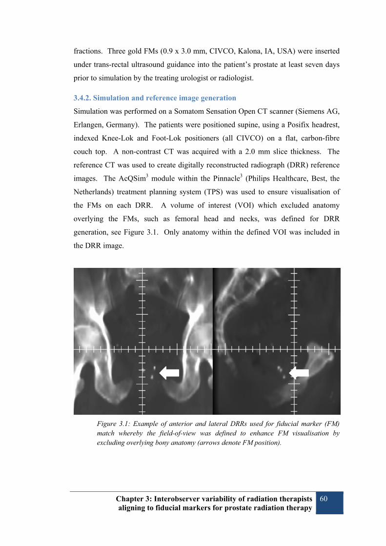
Chapter 3: Interobserver variability of radiation therapists aligning to fiducial markers for prostate radiation therapy
60
fractions. Three gold FMs (0.9 x 3.0 mm, CIVCO, Kalona, IA, USA) were inserted
under trans-rectal ultrasound guidance into the patient’s prostate at least seven days
prior to simulation by the treating urologist or radiologist.
3.4.2. Simulation and reference image generation
Simulation was performed on a Somatom Sensation Open CT scanner (Siemens AG,
Erlangen, Germany). The patients were positioned supine, using a Posifix headrest,
indexed Knee-Lok and Foot-Lok positioners (all CIVCO) on a flat, carbon-fibre
couch top. A non-contrast CT was acquired with a 2.0 mm slice thickness. The
reference CT was used to create digitally reconstructed radiograph (DRR) reference
images. The AcQSim3 module within the Pinnacle3 (Philips Healthcare, Best, the
Netherlands) treatment planning system (TPS) was used to ensure visualisation of
the FMs on each DRR. A volume of interest (VOI) which excluded anatomy
overlying the FMs, such as femoral head and necks, was defined for DRR
generation, see Figure 3.1. Only anatomy within the defined VOI was included in
the DRR image.
Figure 3.1: Example of anterior and lateral DRRs used for fiducial marker (FM) match whereby the field-of-view was defined to enhance FM visualisation by excluding overlying bony anatomy (arrows denote FM position).

Chapter 3: Interobserver variability of radiation therapists aligning to fiducial markers for prostate radiation therapy
61
3.4.3. Localisation image acquisition
All patients were treated on a Varian Clinac iX linear accelerator, incorporating an
On-Board Imager (OBI) kV imaging system (Varian, Palo Alto, CA, USA). Patients
were initially aligned using their external skin marks. Orthogonal kV images
(anterior and right lateral) were obtained to localise the FMs prior to daily treatment.
3.4.4. Online image assessment
Pre-treatment kV images were assessed online using the OBI software prior to each
treatment. Assessment was performed by a treating RT and confirmed by another
treating RT. The registration process consisted of aligning the FMs on the acquired
kV images with the overlaid reference DRRs. Correction for displacement of FMs
was limited to couch translation in the superior-inferior (SI), left-right (LR) and
anterior-posterior (AP) directions. Online localisation to FMs was performed with a
3.0 mm action level. If the isocentre was out of tolerance in any one direction, the
couch shift was performed for all three planes. These online corrections were
performed by applying the couch shift remotely. All online measurements of FM
displacement were recorded in the MOSAIQ electronic medical record (version 1.60,
IMPAC Medical Systems, Sunnyvale, CA, USA), regardless of whether they were
applied.
3.4.5. Offline image assessment
Three RTs (Obs1, Obs2 and Obs3) performed offline FM registration using the
MOSAIQ software. The offline observers had varied experience: 14, 4 and 6 years
of experience as RTs, respectively. Their experience with matching to FMs was less
than one year. Stereoscopic image registration was performed utilising curve
templates drawn around each FM on the reference DRRs.
3.4.6. Statistical analysis
Paired comparisons of observers, in the form of Bland-Altman (187) analysis of
agreement, were performed using Analyse-It® software (Method Evaluation Edition,
Analyse-It Software Ltd, Leeds, UK). This analysis was used to determine the bias,
or mean of the observer differences for the multiple observer pairs. The 95 % limits
of agreement (LoA), defined as the mean of the observer differences ± 1.96 times the
standard deviation (SD) of the differences, were also determined for each observer
pair. Clinically acceptable 95 % LoA were defined as ±2.0 mm. These 95 % LoA

Chapter 3: Interobserver variability of radiation therapists aligning to fiducial markers for prostate radiation therapy
62
were defined to reflect the 3.0 mm action level used in our clinic. The 95 %
confidence intervals (CI) for the mean difference and LoA were also calculated.
3.5. Results
Six patients underwent prostate EBRT utilising daily FM-based localisation between
January and April 2010. Three of the patients received 37 fractions of EBRT while
the other three patients completed 39 fractions. A total of 228 fractions were
delivered. Two fractions were not included in the analysis since the online match
was not recorded. The offline review for one fraction was not possible since the
lateral kV image was unavailable in the MOSAIQ database. Therefore, 225 of the
228 possible treatment fractions were included in the analysis.
3.5.1. Comparison of online and offline observers
The pairwise Bland-Altman analysis of online versus offline observer measurements
is shown in Table 3.1. Typically, the comparison of online and offline observations
were within the predefined ±2.0 mm clinically acceptable 95 % LoA. Interobserver
agreement was best in the LR direction where the 95 % LoA were estimated to be
within ±1.5 mm. For both the SI and AP directions, the 95 % CI of the 95 % LoA
exceeded 2.0 mm, slightly for Obs2 versus OnL and to a greater extent for Obs3
versus OnL. The online and offline observers’ measurements agreed within 2.0mm
or better for 99.1 % fractions in the SI direction; 100.0 % LR; and 99.3 % AP.
3.5.2. Comparison of offline observers
The results of the pairwise Bland-Altman comparison of offline observer
measurements are shown in Table 3.2. All pairwise Bland-Altman analysis of the
offline observers resulted in 95 % LoA within the predefined ±2.0 mm LoA of
clinical acceptability. Interobserver variability between the offline observers was
least evident in the LR direction where agreement was within ±1.5 mm 95 % LoA.
The offline observers’ measurements agreed within 2.0mm or better for 100.0 %
fractions in the SI direction; 100.0 % LR; and 99.7 % AP.

Chapter 3: Interobserver variability of radiation therapists aligning to fiducial markers for prostate radiation therapy
63
Table 3.1: Pairwise Bland-Altman analysis of online and offline observers
Observers Compared
Mean of Difference
(mm)
95 % CI
SD of Difference
Lower 95 % LoA
95 % CI Lower LoA
Upper 95 % LoA
95 % CI
Upper LoA
SI
OnL Obs1 -0.21 -0.32
0.82 -1.82 -2.00
1.40 1.22
-0.10 -1.63 1.59
OnL Obs2 -0.12 -0.24
0.89 -1.86 -2.06
1.62 1.42
0.00 -1.66 1.82
OnL Obs3 -0.26 -0.38
0.88 -1.98 -2.17
1.45 1.26
-0.15 -1.78 1.65
LR
OnL Obs1 0.08 0.00
0.61 -1.11 -1.25
1.27 1.13
0.16 -0.97 1.41
OnL Obs2 0.12 0.04
0.61 -1.08 -1.22
1.32 1.18
0.20 -0.94 1.46
OnL Obs3 0.06 -0.03
0.66 -1.23 -1.37
1.34 1.20
0.14 -1.08 1.49
AP
OnL Obs1 -0.20 -0.29
0.72 -1.60 -1.76
1.21 1.05
-0.10 -1.44 1.37
OnL Obs2 -0.26 -0.37
0.81 -1.85 -2.04
1.33 1.15
-0.16 -1.67 1.51
OnL Obs3 -0.35 -0.47
0.93 -2.17 -2.37
1.47 1.26
-0.21 -1.96 1.68 SI: superior-inferior; LR: left-right; AP: anterior-posterior; OnL: Online; Obs1: offline observer 1; Obs2: offline observer 2; Obs3: offline observer 3; CI: confidence interval; SD: standard deviation; LoA: limit of agreement.
Table 3.2: Pairwise Bland-Altman analysis of offline observers
Observers Compared
Mean of Difference
(mm)
95 % CI
SD of Difference
Lower 95 % LoA
95 % CI
Lower LoA
Upper 95 % LoA
95 % CI Upper LoA
SI
Obs1 Obs2 0.09 0.00
0.68 -1.24 -1.39
1.41 1.26
0.18 -1.08 1.56
Obs1 Obs3 -0.05 -0.14
0.68 -1.38 -1.54
1.28 1.13
0.04 -1.23 1.43
Obs2 Obs3 -0.14 -0.24
0.77 -1.66 -1.83
1.37 1.20
-0.04 -1.48 1.54
LR
Obs1 Obs2 0.04 -0.04
0.58 -1.09 -1.22
1.17 1.04
0.12 -0.96 1.30
Obs1 Obs3 -0.02 -0.11
0.64 -1.27 -1.41
1.23 1.08
0.06 -1.13 1.37
Obs2 Obs3 -0.06 -0.15
0.64 -1.33 -1.47
1.20 1.06
0.02 -1.18 1.35
AP
Obs1 Obs2 -0.07 -0.16
0.74 -1.51 -1.68
1.38 1.21
0.03 -1.35 1.55
Obs1 Obs3 -0.15 -0.25
0.79 -1.69 -1.87
1.39 1.22
-0.05 -1.52 1.57
Obs2 Obs3 -0.08 -0.20
0.86 -1.77 -1.96
1.60 1.41
0.03 -1.58 1.79
SI: superior-inferior; LR: left-right; AP: anterior-posterior; OnL: Online; Obs1: offline observer 1; Obs2: offline observer 2; Obs3: offline observer 3; CI: confidence interval; SD: standard deviation; LoA: limit of agreement.
Chapter 3: Interobserver variability of radiation therapists aligning to fiducial markers for prostate radiation therapy
64
3.6. Discussion
This study examined whether, when using planar kV imaging, RTs were able to
align FMs within clinically acceptable limits. As we have transitioned from bony
alignment to the use of FMs, it is important to examine the accuracy of image
guidance methods. An understanding of interobserver variability is especially
important to inform comparison of planar and volumetric methods as the use of
CBCT and soft-tissue alignment increases. The study has demonstrated that RTs are
able to accurately and consistently align FMs in order to autonomously perform
daily FM-based image-guided prostate EBRT.
Comparisons of the online and offline observers were typically within the predefined
clinically acceptable 2.0 mm 95 % LoA. The mean differences between online and
offline measurements were very small (<0.4 mm) and demonstrate RTs are able to
consistently and accurately localise to FMs, whether in the busy online environment
or offline.
Since this study was performed with a 3.0 mm action level for the online
observations, it was a concern that online observers may have tended to measure
displacements less than the 3.0 mm action level in order to avoid performing a couch
shift. The recent study by Gill et al.(202) outlined situations when treating RTs may
be influenced toward not performing couch shifts. Measurements from a linear
accelerator with automated couch corrections were significantly greater than those
for the unit which required manual couch adjustments. Gill et al.(202) suggested
that the lack of couch automation may have contributed to the likelihood of
measurements under the action threshold. In our study, the RTs utilised the remote
couch to apply any couch shifts, but were required to perform additional verification
imaging after any shift. Therefore the decision to perform a couch shift (measuring
displacement ≥ 3.0 mm) would have added extra time to the treatment session.
To determine whether the small difference between online and offline observers is
clinically meaningful, we examined whether the online matching resulted in fewer
fractions having couch adjustments than were expected from the offline
measurements. Overall, there were 147 fractions (65.3 %) where a displacement ≥

Chapter 3: Interobserver variability of radiation therapists aligning to fiducial markers for prostate radiation therapy
65
3.0mm was measured online. Similarly, there were 144 fractions (64.0 %) where all
three offline observers measured a displacement ≥ 3.0 mm, suggesting the online
observers did not avoid applying couch shifts by aligning below the action level.
Since the conclusion of this study, we have introduced a 0.0 mm action level within
our clinic, whereby all displacements are corrected using the remote couch for all
treatment fractions.
It is possible that the small differences in online and offline measurements were due
to a limitation of the study whereby image registration was performed in two
separate software packages with different alignment methods. All online
assessments were performed using the Varian OBI software whereas offline
registration was performed in MOSAIQ. The online registration consisted of
overlaying the reference and verification images while offline alignment used curves
drawn around the FMs on the reference DRR.
Examination of the offline observers alone removes the influence of the online action
level and any differences in the method of alignment. Differences between the
offline observers were smaller than the differences between the online and offline
observers. The offline observers demonstrated high degree of agreement, well
within the ±2.0 mm level predefined for clinical acceptability. This result further
demonstrates the consistency of alignment to FMs by RTs.
3.7. Conclusion
The results of this study have demonstrated clinically acceptable agreement between
RTs assessing kV images when matching to FMs. It has shown that RTs are able to
accurately and consistently perform prostate IGRT. It will be important to confirm
that similar consistency is achieved with volumetric imaging modalities, such as
cone beam CT. Potential clinical advantages from the online use of CBCT, such as
visualisation of the clinical target volume and organs at risk will need to be
considered in the context of the RTs ability to accurately and consistently interpret
and align these images.

Chapter 3: Interobserver variability of radiation therapists aligning to fiducial markers for prostate radiation therapy
66
3.8. Acknowledgements
This project has been supported by funding from the Princess Alexandra Hospital
Private Practice Trust Fund and the Medical Radiation Technologists Board of
Queensland. Thanks to Melanie Watson from the Statistical Analysis Unit, Health
Statistics Centre, Queensland Health, for her advice in the design and statistical
analysis of this study. Thanks to the staff of Radiation Oncology Mater Centre who
have participated in the treatment of the patients included in this study.

Chapter 3: Interobserver variability of radiation therapists aligning to fiducial markers for prostate radiation therapy
67
3.9. Additional material
An example Bland-Altman plot, not included in published article, is included below:
Figure 3.2: Example Bland-Altman plot of interobserver agreement (observer 1 compared with observer 2) in the (a) superior-inferior, (b) left-right, and (c) anterior-posterior directions.


Chapter 4: Assessment of cone beam CT registration for prostate radiation therapy: fiducial marker and soft-tissue methods
69
Chapter 4: Assessment of cone beam CT registration for prostate radiation therapy: fiducial marker and soft-tissue methods
Authors:
Mr Timothy Deegan, BAppSc (MRT) 1, 2
Dr Rebecca Owen, PhD, FIR 1, 3
Dr Tanya Holt, MBBS, FRANZCR 1, 4
Dr Andrew Fielding, PhD 2
Ms Jennifer Biggs, DipAppSc (Ther Rad) 1
Mr Matthew Parfitt, BAppSc (MRT) 1
Ms Alicia Coates, BAppSc (MRT) 1
Ms Lisa Roberts, MHlthMan 5
1 Radiation Oncology Mater Centre, South Brisbane, Australia
2 Science and Engineering Faculty, Queensland University of Technology, Brisbane,
Australia
3 Faculty of Health, Queensland University of Technology, Brisbane, Australia
4 University of Queensland, St Lucia, Australia
5 Cancer and Blood Disorders, Gold Coast University Hospital, Southport,
Queensland

Chapter 4: Assessment of cone beam CT registration for prostate radiation therapy: fiducial marker and soft-tissue methods
70
4.1. Statement of contribution of co-authors
The authors listed below have certified* that:
6. They meet the criteria for authorship in that they have participated in the
conception, execution, or interpretation, of at least that part of the publication in
their field of expertise;
7. They take public responsibility for their part of the publication, except for the
responsible author who accepts overall responsibility for the publication;
8. There are no other authors of the publication according to these criteria;
9. Potential conflicts of interest have been disclosed to (a) granting bodies, (b) the
editor or publisher of journals or other publications, and (c) the head of the
responsible academic unit, and
10. They agree to the use of the publication in the student’s thesis and its publication
on the QUT ePrints database consistent with any limitations set by publisher
requirements.
In the case of this chapter: Assessment of cone beam CT registration for prostate
radiation therapy: fiducial marker and soft-tissue methods. J Med Imaging Radiat
Oncol 2015; 59(1):91-98.
Principal Supervisor Confirmation: I have sighted email or other correspondence
from all co-authors confirming their certifying authorship.
Name: Andrew Fielding
Signature:
Date: 26/2/15

Chapter 4: Assessment of cone beam CT registration for prostate radiation therapy: fiducial marker and soft-tissue methods
71
Contributor Statement of contribution*
Timothy Deegan wrote the manuscript experimental design conducted experiments data analysis
Signature:
Date: 26th February 2015
Rebecca Owen* aided experimental design data analysis manuscript review
Tanya Holt* aided experimental design data analysis manuscript review
Lisa Roberts* aided experimental design manuscript review
Jennifer Biggs* aided experimental design conducted experiments manuscript review
Alicia McCarthy* aided experimental design conducted experiments
Matthew Parfitt* aided experimental design conducted experiments
Andrew Fielding* aided experimental design data analysis manuscript review

Chapter 4: Assessment of cone beam CT registration for prostate radiation therapy: fiducial marker and soft-tissue methods
72
4.2. Abstract:
4.2.1. Introduction
This investigation aimed to assess the consistency and accuracy of radiation
therapists (RTs) performing cone beam computed tomography (CBCT) alignment to
FMs (CBCTFM) and the soft-tissue prostate (CBCTST).
4.2.2. Methods
Six patients receiving prostate radiation therapy underwent daily CBCTs. Manual
alignment of CBCTFM and CBCTST was performed by three RTs. Interobserver
agreement was assessed using a modified Bland-Altman analysis for each alignment
method. Clinically acceptable 95 % limits of agreement with the mean (LoAmean)
were defined as ±2.0 mm for CBCTFM and ±3.0 mm for CBCTST. CBCTST
alignment was compared with the mean CBCTFM (AvCBCTFM) alignment.
Clinically acceptable 95 % limits of agreement (LoA) were defined as ±3.0 mm for
the comparison of CBCTST and AvCBCTFM.
4.2.3. Results
CBCTFM and CBCTST alignments were performed for 185 images. The CBCTFM 95
% LoAmean were within ±2.0 mm in all planes. CBCTST 95 % LoAmean were within
±3.0 mm in all planes. Comparison of CBCTST with AvCBCTFM resulted in 95 %
LoA of -4.9 to 2.6 mm, -1.6 to 2.5 mm, and -4.7 to 1.9 mm in the superior-inferior,
left-right and anterior-posterior planes respectively.
4.2.4. Conclusions
More interobserver variability was found for soft-tissue alignment than for FMs.
Significant differences were also found between soft-tissue alignment and the
predicted FM position. Consideration needs to be given to margin design when
using soft tissue matching due to increased interobserver variability. This study
highlights that soft-tissue guidance is complex and includes numerous uncertainties.
4.2.5. Key Words
Cone beam computed tomography; Radiotherapy, Image-Guided; Observer
Variation; Prostate

Chapter 4: Assessment of cone beam CT registration for prostate radiation therapy: fiducial marker and soft-tissue methods
73
4.3. Introduction
The importance of ensuring accurate prostate localisation for external beam radiation
therapy (EBRT) has been widely demonstrated.(51, 109, 170) Image-guided
radiation therapy (IGRT) with fiducial markers (FMs) has been shown to provide an
accurate method of correction for internal prostate motion.(129, 131) IGRT has
facilitated dose-escalation by allowing reduced planning target volume (PTV)
margins.(207) The use of FMs is generally well-tolerated(19, 121) and has been
shown to decrease the incidence of acute(208) and late(171) gastrointestinal and
genitourinary toxicity.
While FM-based IGRT is regarded as safe and efficient, there are associated risks
and complications. Trans-rectal implantation of FMs has been shown to cause
patient discomfort, haematuria, rectal bleeding and infection.(18, 19) Recently, there
has been increasing concern regarding risk of multi-drug resistant bacterial infection
following trans-rectal biopsy or FM insertion.(135, 209) Some patients are ineligible
or unwilling to undergo the invasive procedure required, for example due to
anticoagulant dependence. Use of FMs can also place financial burden on the clinic
and patient. Additionally, since FMs act as a surrogate of prostate position, they do
not provide direct information regarding surrounding organs-at-risk (OARs).
An alternative IGRT method is cone beam computed tomography (CBCT) which
provides visualisation of the soft-tissue prostate, seminal vesicles and adjacent
OARs, at the time of treatment.(146, 210) CBCT potentially allows accurate
localisation without the use of FMs.
While it has been shown that RTs consistently align FMs on planar imaging(13,
211), it is not clear how much variability exists with CBCT-based soft-tissue
registration.(13) This study aims to determine whether RTs, who are directly
responsible for the daily IGRT procedure, are able to consistently and accurately
align the prostate using CBCT.

Chapter 4: Assessment of cone beam CT registration for prostate radiation therapy: fiducial marker and soft-tissue methods
74
4.4. Methods
4.4.1. Patient selection and preparation
Six patients undergoing radical EBRT for localised prostate cancer between June and
September 2010 were recruited for this investigation. The study protocol was
approved by the Princess Alexandra Hospital Human Research Ethics Committee
and each patient provided written informed consent.
4.4.2. Simulation and reference image generation
Each patient received three intra-prostatic FMs (0.9 x 3.0 mm, CIVCO, Kalona, IA,
USA), at least 7 days prior to simulation. CT simulation was performed using a
Siemens Sensation Open (Siemens AG, Erlangen, Germany). Reference CTs were
acquired using a 120 kV beam and 3.0 mm slice thickness. Dosimetry was
performed in the Pinnacle3 (Philips Healthcare, Eindhoven, the Netherlands)
radiation treatment planning system.
4.4.3. Cone beam CT image acquisition method
Daily CBCTs were acquired using a Varian Clinac iX linear accelerator
incorporating an On-Board Imager (OBI) (Varian Medical Systems, Palo Alto, CA,
USA). CBCTs were acquired with a source voltage of 125 kVp and a source-to-
detector distance of 150 cm. The CBCT acquisition protocol used a half-fan, half-
bow-tie filter arrangement with a 360 degree gantry rotation. Reconstruction was
performed with a 512 x 512 resolution and 2.0 mm slice thickness. Immediately
following acquisition of the CBCT, orthogonal planar kilovoltage (kV) images were
obtained for FM-based treatment localisation.
4.4.4. Radiation Therapist Observers
The three observers had between 5 and 15 years’ experience as RTs and
approximately two years’ experience with planar FM-based IGRT, but had limited
experience CBCT (<6 months). The RTs were instructed to perform registrations in
a clinically relevant timeframe. In order to approximate the online environment,
offline CBCT registration was performed at the linear accelerator, using the online
Varian OBI 3D/3D match software tools (Varian Medical Systems, Palo Alto, CA,
USA).
Chapter 4: Assessment of cone beam CT registration for prostate radiation therapy: fiducial marker and soft-tissue methods
75
4.4.5. Fiducial marker localisation (CBCTFM)
Three RTs independently performed manual co-registration of the FMs on CBCT
(CBCTFM) with the FMs on the reference CT. Alignment, without use of rotations,
was performed offline and the resultant couch translations were recorded.
4.4.6. Soft-tissue prostate localisation (CBCTST)
Three RTs independently performed manual alignment of the soft-tissue prostate
(CBCTST) using the prostate, seminal vesicles, rectum and bladder contours, as
delineated on the reference CT. The RTs were restricted to contour-based
registration in order to minimise bias due to visualisation of FMs on the reference
CT. The RTs were able to utilise the transverse, sagittal and coronal plane views,
and adjust the window/level at any time. Required couch shifts, without use of
rotations, were recorded for each CBCT.
4.4.7. Statistical analysis
4.4.7.1. Interobserver Agreement: CBCTFM and CBCTST
To assess agreement between the three observers, couch shifts were compared for
each of the CBCTFM and CBCTST methods using the process described by Jones et
al.(204) In this modified Bland-Altman(187) analysis, each observer was compared
with the mean shift of all observers. The modified Bland-Altman analysis
determined the 95 % limits of agreement with the mean (LoAmean), defined as ±1.96
x s, where s = the population standard deviation (SD).(204) Agreement plots
providing a visual assessment of interobserver variability were created.(204) The
mean, SD and range of measurements for each observer were also calculated.
Calculations were performed using Microsoft Excel 2010 (Microsoft, Redmond,
WA, USA). To assess the clinical significance of the interobserver agreement, a
threshold for acceptability was set at 95 % LoAmean ≤ ±2.0 mm for CBCTFM and ≤
±3.0 mm for CBCTST. The ±2.0 mm CBCTFM acceptability threshold was based on
knowledge of alignment of FMs on planar imaging.(211) The ±3.0 mm threshold for
CBCTST was equivalent to the departmental online action level. We report
agreement within ±2.0 mm and ±3.0 mm for each method.

Chapter 4: Assessment of cone beam CT registration for prostate radiation therapy: fiducial marker and soft-tissue methods
76
4.4.7.2. Method Comparison: CBCTST and CBCTFM
To assess accuracy of the soft-tissue localisation method, the CBCTST results were
compared with the established standard of FM alignment using the method described
by Bland and Altman(187) for comparing two methods of measurement. The
baseline FM position was estimated by obtaining the mean of the CBCTFM position
from the three observers for each fraction (AvCBCTFM). Bland-Altman analysis
determined the mean and SD of the method differences. The 95 % limits of
agreement (LoA), defined as the mean of the differences ± 1.96 times the SD of the
differences, were also calculated.(187) Calculations were performed using Analyse-
It® software (Method Evaluation Edition, Analyse-It Software Ltd, Leeds, UK). To
assess whether CBCTFM and CBCTST could be considered interchangeable, a
threshold for clinical acceptability was set at 95 % LoA ≤ ±3.0 mm.
4.5. Results
Six prostate adenocarcinoma (T1c to T2b) patients underwent radical EBRT between
June and September 2010. Their median age was 69.6 years (Range: 61.2 to 74.7
years) and average prostate volume was 36.4 cm3 (Range: 20.5 to 56.7 cm3). A total
of 227 fractions were delivered. CBCTs were not acquired for 16 fractions (7.0 %)
due to hardware issues or workload constraints. An additional 26 CBCTs (11.5 %)
were not saved locally within the OBI system and were unavailable for offline
review. Overall, 185 (81.5 %) of the possible 227 CBCTs were included in the
analysis. Each patient had between 29 and 33 CBCTs included.
4.5.1. Interobserver agreement: CBCTFM
The FMs were easily visualised on all CBCTs, except four fractions where distortion
of FMs due to motion during image acquisition was observed. An example of
adequate visualisation is shown in Figure 4.1 and FM distortion in Figure 4.2. The
mean, SD and range of the CBCTFM alignment for each observer in each plane are
shown in Table 4.1. Modified Bland-Altman agreement plots of CBCTFM are shown
in Figure 4.3. The 95 % LoAmean were within the predetermined clinically
acceptable limit of ±2.0 mm in all planes. Interobserver agreement was best in the
LR direction where the 95 % LoAmean was calculated to be ±0.8 mm. The 95 %
LoAmean in the SI and AP planes were ±1.1 mm and ±1.2 mm respectively. The

Chapter 4: Assessment of cone beam CT registration for prostate radiation therapy: fiducial marker and soft-tissue methods
77
percentage of observer-pair agreement within 2.0 mm was 98.7 %, 100.0 % and 97.7
% in the SI, LR and AP directions respectively. The percentage of observer-pair
agreement within 3.0 mm was 99.8 % (SI), 100.0 % (LR) and 99.3 % (AP).
Figure 4.1: Example of a good quality CBCT, demonstrating adequate visualisation of the soft-tissue anatomy in the (a) transverse; (b) coronal; and (c) sagittal planes. One of the fiducial markers can be seen in (a).
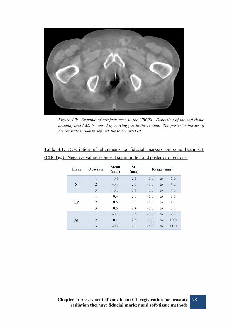
Chapter 4: Assessment of cone beam CT registration for prostate radiation therapy: fiducial marker and soft-tissue methods
78
Figure 4.2: Example of artefacts seen in the CBCTs. Distortion of the soft-tissue anatomy and FMs is caused by moving gas in the rectum. The posterior border of the prostate is poorly defined due to the artefact.
Table 4.1: Description of alignments to fiducial markers on cone beam CT
(CBCTFM). Negative values represent superior, left and posterior directions.
Plane Observer Mean (mm)
SD (mm)
Range (mm)
SI
1 -0.5 2.1 -7.0 to 5.0
2 -0.8 2.3 -8.0 to 4.0
3 -0.5 2.1 -7.0 to 4.0
LR
1 0.4 2.3 -5.0 to 8.0
2 0.5 2.3 -6.0 to 8.0
3 0.5 2.4 -5.0 to 8.0
AP
1 -0.3 2.6 -7.0 to 9.0
2 0.1 2.6 -6.0 to 10.0
3 -0.2 2.7 -8.0 to 11.0

Chapter 4: Assessment of cone beam CT registration for prostate radiation therapy: fiducial marker and soft-tissue methods
79
Figure 4.3: Modified Bland–Altman plots demonstrating the 95% limits of agreement with the mean (LoAMean) for multiple observers aligning to fiducial markers (cone beam computed tomography alignment to fiducial markers) (CBCTFM)) in the superior–inferior (SI), left–right (LR) and anterior–posterior (AP) planes (a, c, and e, respectively). The plots for CBCT alignment to soft tissue prostate (CBCTST) are shown in the SI, LR and AP planes (b, d, and f, respectively X, Observer 1; ●, Observer 2; ▲, Observer 3; ―, 95% LoAMean; - - -, clinically acceptable threshold.

Chapter 4: Assessment of cone beam CT registration for prostate radiation therapy: fiducial marker and soft-tissue methods
80
4.5.2. Interobserver agreement: CBCTST
The mean, SD and range of the CBCTST alignment for each observer in each plane
are shown in Table 4.2. Modified Bland-Altman comparisons of CBCTST are plotted
in Figure 4.3. The 95 % LoAmean results were within the predefined clinically
acceptable of ±3.0 mm in all planes. Interobserver agreement was again best in the
LR direction where the 95 % LoAmean was calculated to be ±1.5 mm. The 95 %
LoAmean in the SI and AP planes were ±2.5 mm and ±2.0 mm respectively. The
percentage of observer-pair agreement within 2.0 mm was 76.0 %, 94.6 % and 84.1
% in the SI, LR and AP directions respectively. The percentage of observer-pair
agreement within 3.0 mm was 90.6 % (SI), 98.9 % (LR) and 95.0 % (AP).
Table 4.2: Description of alignments to soft-tissue on cone beam CT (CBCTST).
Negative values represent superior, left and posterior directions.
Plane Observer Mean (mm)
SD (mm)
Range (mm)
SI
1 0.4 2.2 -6.0 to 10.0
2 0.2 1.6 -5.0 to 4.0
3 1.0 2.0 -5.0 to 8.0
LR
1 0.3 2.2 -5.0 to 8.0
2 0.1 2.0 -5.0 to 6.0
3 -0.3 2.4 -8.0 to 9.0
AP
1 1.2 2.3 -5.0 to 9.0
2 1.2 1.8 -3.0 to 10.0
3 1.4 2.1 -4.0 to 10.0
4.5.3. Method Comparison: CBCTST and CBCTFM
The results of Bland-Altman comparison of CBCTST and CBCTFM are shown in
Table 4.3. Mean differences between CBCTST and CBCTFM indicated that the RTs
tended to systematically match the soft-tissue 1.1 mm more inferior and 1.4 mm
more anterior than predicted by the FM position.
The 95 % LoA were within the clinically acceptable range of ±3.0 mm in the LR
plane, but were -4.9 to 2.6 mm in the SI plane and -4.7 to 1.9 mm in the AP
direction. The percentage of CBCTFM and CBCTST agreement within 3.0 mm was
86.3 %, 99.6 % and 84.7 % in the SI, LR and AP directions respectively. At least
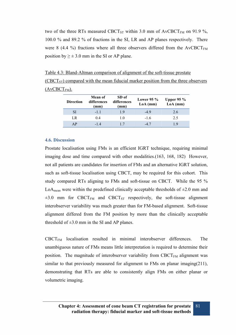
Chapter 4: Assessment of cone beam CT registration for prostate radiation therapy: fiducial marker and soft-tissue methods
81
two of the three RTs measured CBCTST within 3.0 mm of AvCBCTFM on 91.9 %,
100.0 % and 89.2 % of fractions in the SI, LR and AP planes respectively. There
were 8 (4.4 %) fractions where all three observers differed from the AvCBCTFM
position by ≥ ± 3.0 mm in the SI or AP plane.
Table 4.3: Bland-Altman comparison of alignment of the soft-tissue prostate
(CBCTST) compared with the mean fiducial marker position from the three observers
(AvCBCTFM).
Direction Mean of
differences (mm)
SD of differences
(mm)
Lower 95 % LoA (mm)
Upper 95 % LoA (mm)
SI -1.1 1.9 -4.9 2.6
LR 0.4 1.0 -1.6 2.5
AP -1.4 1.7 -4.7 1.9
4.6. Discussion
Prostate localisation using FMs is an efficient IGRT technique, requiring minimal
imaging dose and time compared with other modalities.(163, 168, 182) However,
not all patients are candidates for insertion of FMs and an alternative IGRT solution,
such as soft-tissue localisation using CBCT, may be required for this cohort. This
study compared RTs aligning to FMs and soft-tissue on CBCT. While the 95 %
LoAmean were within the predefined clinically acceptable thresholds of ±2.0 mm and
±3.0 mm for CBCTFM and CBCTST respectively, the soft-tissue alignment
interobserver variability was much greater than for FM-based alignment. Soft-tissue
alignment differed from the FM position by more than the clinically acceptable
threshold of ±3.0 mm in the SI and AP planes.
CBCTFM localisation resulted in minimal interobserver differences. The
unambiguous nature of FMs means little interpretation is required to determine their
position. The magnitude of interobserver variability from CBCTFM alignment was
similar to that previously measured for alignment to FMs on planar imaging(211),
demonstrating that RTs are able to consistently align FMs on either planar or
volumetric imaging.

Chapter 4: Assessment of cone beam CT registration for prostate radiation therapy: fiducial marker and soft-tissue methods
82
While our comparison of FM and soft-tissue alignment resulted in variability in
excess of the predefined clinically acceptable limits, the results do compare
favourably with other published data. In a comparison of CBCTST and CBCTFM,
Moseley et al.(13) reported 95 % LoA in excess of 5.0 mm in the SI and AP planes.
Moseley’s results were similar to our current study in the LR plane and interobserver
variability was considered the largest source of uncertainty for soft-tissue alignment.
Despite large differences between soft-tissue and FM alignment, Moseley concluded
that CBCT was an accurate means of soft-tissue IGRT provided that PTV margins in
the order of 10.0 mm were maintained. For their comparison of soft-tissue and FM
alignment, Barney et al.(182) defined acceptable differences to be within their PTV
margin of 5.0 mm, which was only achieved in the LR plane. Barney concluded that
planar imaging with FMs was the preferred IGRT method. Temporal differences
could account for some of the inconsistency in Barney’s results as the FM position
was obtained from planar imaging rather than CBCT. As shown by these two
studies, the clinical acceptability of soft-tissue localisation with CBCT is largely
dependent on the size of PTV margins. Subsequently, PTV margins need to be
appropriate tailored to account for the uncertainties of different localisation methods
to be used.
The larger interobserver variability found for CBCTST compared with CBCTFM
alignment can be attributed to CBCT image quality, which is generally inferior to the
reference CT and is affected by low contrast-to-noise ratio, motion artefacts due to
the long image acquisition time and moving gas-induced artefacts.(110, 155, 212)
Subsequently, it can be difficult to distinguish the soft-tissue prostate from adjacent
structures, particularly at the base and apex due to similar densities (e.g. rectum,
bladder, muscles).(199, 200)
Comparison of CBCTST and CBCTFM is difficult since there is no “ground-truth” for
the prostate position. Since FMs are the accepted gold-standard method for prostate
localisation, the FM position has been accepted as the truth in this study. This
assumption belies the fact that the prostate can deform relative to FMs.(102) It is
possible that some of the differences between CBCTST and CBCTFM may be because

Chapter 4: Assessment of cone beam CT registration for prostate radiation therapy: fiducial marker and soft-tissue methods
83
the FM position did not accurately reflect the prostate position rather than because of
poor soft-tissue localisation.
The use of contour-based alignment within this study may have contributed to
CBCTST alignment variability. The underlying reference CT was not used in order
to reduce the influence of the FMs. While Court et al.(198) found contour-based
alignment was sufficiently accurate and use of the reference CT made only small
improvements to interobserver consistency, contour-based registration precludes use
of distinctive anatomical landmarks such as intraprostatic calcifications which have
been shown to be advantageous in prostate alignment.(213) Clinically, use of the
reference CT may improve CBCTST interobserver agreement.
While the position of FMs on the reference CT was unknown to the RTs,
visualisation of FMs on the CBCTs may have aided soft-tissue alignment since the
FMs are indicative of prostate position. We were unable to remove FMs from the
projection data as has been done in other studies.(13, 199) The variation between
CBCTFM and CBCTST may be underestimated due to the presence of FMs in the
CBCTs. The large differences observed between CBCTFM and CBCTST suggest it is
unlikely that the FMs did cause such a bias. In contrast, it is possible that artefacts
caused by the FMs distorted the boundary of the prostate, causing a source of
alignment uncertainty.
The number of observers included in this study was limited due to the time required
for CBCTFM and CBCTST registrations by each observer. Inclusion of more RTs
may have resulted in more precise estimation of interobserver variability for each of
the CBCTFM and CBCTST strategies. The finding that soft-tissue alignment has
greater interobserver variability than matching FMs is unlikely to change with more
observers.
It is possible that the sample size of six patients meant the RTs became familiar with
anatomical features when performing soft-tissue registration, thereby increasing the
consistency of alignment. Study design may have been improved by including more
patients and fewer images per patient. Internal prostate motion and variations in

Chapter 4: Assessment of cone beam CT registration for prostate radiation therapy: fiducial marker and soft-tissue methods
84
rectal and bladder size can, though, reduce this effect. The differences between
CBCTFM and CBCTST would be unlikely to change significantly with increased
sample size.
The introduction of soft-tissue alignment has several workflow and training
implications. Since at least one observer aligned CBCTST within 3.0 mm of the
CBCTFM position on 95.6 % fractions, we recommend that two RTs perform
localisation. This practice may serve to improve consistency of soft-tissue alignment.
The RTs participating in this study had limited prior experience performing CBCTST
prostate localisation. This may partly explain the interobserver variation found. As
RTs gain more experience with CBCTST it is reasonable to expect that observer
agreement will improve. Sahota et al.(214) identified the use of anatomy atlases as a
means of improving the ability and confidence of RTs to identify structures on post-
prostatectomy CBCTs. White et al.(199) also recommended training RTs in image
guidance and image recognition as well as development of IGRT protocols in order
to reduce the risk of localisation errors. Since the conclusion of this investigation,
we have sought to reduce CBCTST interobserver variability by developing in-house
training to improve knowledge and understanding of anatomy and IGRT decision-
making.
4.7. Conclusion
This study quantifies the interobserver variability when RTs align FMs or soft-tissue
on CBCT. It also directly compares CBCT localisation based on soft-tissue and
FMs. Interobserver variability was considerably greater for soft-tissue alignment
compared with FMs. Large differences between soft-tissue localisation and FM
position were found. The implementation of soft-tissue guidance protocols should
only be performed with the understanding that localisation results can differ between
IGRT modalities. Incorporating the results of an evaluation of local IGRT
performance into margin calculation is necessary to ensure the risk of geometric miss
is minimised. This study adds to the evidence that IGRT is complex and includes
numerous uncertainties.

Chapter 4: Assessment of cone beam CT registration for prostate radiation therapy: fiducial marker and soft-tissue methods
85
4.8. Acknowledgements
This study has received support from the Private Practice Trust Fund, Princess
Alexandra Hospital and the Medical Radiation Technologists Board of Queensland.
The authors wish to thank staff and management of Radiation Oncology Mater
Centre who have supported this study as well as CEH for her advice and assistance.


Chapter 5: Discussion 87
Chapter 5: Discussion 5.1. Discussion
IGRT is an essential part of the radiation therapy process and is critical to ensuring
accurate dose delivery. It is important for each radiotherapy department to ensure
their IGRT processes are of high quality.(215) This investigation of IGRT methods
coincided with the introduction of new IGRT technology within ROMC. It was
designed to compare two forms of IGRT for prostate EBRT, i.e., planar kV imaging
using FMs and soft-tissue localisation with CBCT. The purchase of two new linear
accelerators (linacs) with the capability for kV imaging (planar and volumetric)
resulted in the replacement of two units which had no electronic imaging capability,
and had therefore relied on film-based verification. Two other linacs within the
department utilised low resolution ion chamber EPIDs for treatment localisation.
The availability of new imaging technology presented an opportunity to critically
assess and improve IGRT methods.
The primary aim of this investigation was to compare prostate localisation with
planar and volumetric kV imaging in terms of localisation agreement and
interobserver variability. This was motivated by the desire to determine whether
CBCT could be used to accurately and consistently align the prostate, without the
use of FMs. In order to determine the consistency of prostate IGRT, with and
without FMs, multiple RTs were asked to align either FMs or soft-tissue on planar
and volumetric imaging. The isocentre placement from FMs and soft-tissue was
compared to determine how well each IGRT method agreed. Interobserver
agreement was also determined for each IGRT method.
The first aim of this research was to compare the isocentre localisation results from
soft-tissue alignment using CBCT with the localisation from alignment to FMs. Our
results demonstrated considerable differences between these methods, discussed
further in Section 5.1.3. A further aim of this investigation was to evaluate the
consistency of RTs aligning to FMs on planar kV imaging. Excellent interobserver
agreement was found in both the online and offline workflows, supporting the
widespread use of this technique (discussed further in Section 5.1.1.). An additional
aim was to determine the consistency of RTs aligning to soft-tissue on volumetric

Chapter 5: Discussion 88
kV CBCT imaging. While large interobserver variations where found for the soft-
tissue alignment, the use of FMs was observed to improve interobserver agreement
when performing kV CBCT-based IGRT (Discussed in Section 5.1.2.).
Measurement of agreement with either the Bland-Altman(20, 187) or Jones(204)
methods relies on the assumption that (i) no relation exists between the difference
and mean; and (ii) the differences follow a normal distribution. Each of these
assumptions was satisfied in the calculation of results for Chapters 3 and 4.
5.1.1. Interobserver variability: FMs
Prostate localisation based on FMs has become the standard of care in Australia and
internationally.(16, 215) The results of this investigation support the use of FMs as a
surrogate of prostate position by demonstrating excellent interobserver agreement for
RTs’ alignment to FMs on planar kV imaging and on kV CBCT. RTs were able to
align FMs within the clinically acceptable thresholds on either planar (±2.0 mm 95%
LoA) or volumetric imaging (±3.0 mm 95% LoA), as well as in the online and
offline environment.
The transition from localisation using bony anatomy to FM-based guidance was, in
technical terms, relatively simple. Prior to the introduction of FM-based IGRT at
ROMC, the RTs had become proficient with the hardware and software used for
planar kV imaging based on bony anatomy. Since the RTs also had been performing
MV planar imaging with ion-chamber EPIDs for many years the improved image
quality was welcomed when performing online corrections. In terms of image
acquisition and review, the process for FM-based IGRT was similar to that used for
bony alignment. The use of FMs can be considered a simplification of the image-
guidance process compared with bony alignment since it relies on three discrete
points rather than interpretation of several bony landmarks.
The finding that RTs are able to register FMs with high consistency is supported by
recent literature, some published since the initiation of this study. Chung et al., has
reported that the majority of RTs consider alignment of FMs using planar imaging
can be performed with ease.(126) Kong et al. demonstrated that alignment to FMs
was performed with much less interobserver variability than alignment to bony

Chapter 5: Discussion 89
anatomy.(196) The excellent agreement between online and offline observers found
in the current study highlights that RTs are able to accurately perform FM
localisation with kV planar imaging under the pressure of the online environment.
In order to better compare the results from Chapter 3 and Chapter 4, we can
recalculate the Chapter 3 interobserver agreement according to the modified Bland-
Altman analysis described by Jones et al. used in Chapter 4. This method of
comparing multiple observers was unknown to us at the time of preparing the
investigation of planar imaging (Chapter 3). Using the data from the offline
observers, calculation of interobserver agreement in terms of 95 % LoAmean for kV
planar imaging is demonstrated in Table 5.1.
Table 5.1: 95 % LoAmean for various IGRT methods
Alignment Method SI
(mm) LR
(mm) AP
(mm) kV planar: FMs† 0.8 0.7 0.9 kV CBCT: FMs‡ 1.1 0.8 1.2 kV CBCT: soft-tissue‡ 2.5 1.5 2.0 †recalculated from Chapter 3 results ‡as published in Chapter 4
Interestingly, we have found that interobserver variability for alignment of FMs is
slightly greater on CBCT than for planar imaging (see Table 5.1). This is likely due
to differences in the image acquisition process between planar and volumetric
imaging, and also due to differences in the process of reviewing these images. Since
planar imaging is acquired with millisecond exposures, the FMs are well defined
with sharp edges. The longer acquisition time of CBCT increases the likelihood of
motion blurring and the FMs on CBCT are less sharp. Examples of FMs imaged
with planar and volumetric images are shown in Figure 5.1.

Chapter 5: Discussion 90
Figure 5.1: (a) planar image of FMs; (b) axial slice of CBCT demonstrating
distortion of FM. The FM is distorted in the CBCT due to motion during the
relatively longer image acquisition with respect to planar imaging.
When performing image registrations within this study, the observers remarked that
it was easier to evaluate the “best-fit” of the three markers on planar imaging.
Alignment of the FMs on CBCT was found to be more subjective since the FMs
could not be evaluated simultaneously. When comparing alignment of FMs on kV
planar and CBCT images, Owen et al. also found that differences in the nature of
planar and volumetric image review contributed to differences in localisation
position.(181)
5.1.2. Interobserver variability: soft-tissue
Alignment to the soft-tissue prostate was found to result in considerably greater
interobserver variability compared with alignment to FMs. It is likely that factors
such as image quality, patient characteristics and the nature of the observers all
contribute to the interobserver variability found in this investigation. The degree of
interobserver variability found in this study adds to the evidence that the image
quality of CBCT results in highly subjective interpretation of the soft-tissue.
The reduced image quality of CBCT has been identified by Stock et al., who found
contrast-to-noise ratio was, on average, 51 % higher for CT than for CBCT.(212)
The lack of collimation inherent in CBCT also results in poorer low-contrast-

Chapter 5: Discussion 91
visibility which is relevant for differentiating soft-tissue structures.(212) CBCT also
suffers from a relatively long image acquisition time which can lead to image
blurring subsequent to patient and organ motion. Of particular relevance in prostate
CBCTs is the potential for moving bowel gas resulting in degraded image quality.
As a result of the poor CBCT image quality, there is significant difficulty discerning
the prostatic base and apex. This is also the case of diagnostic quality FBCT.
As evidenced by delineation studies, the reduced image quality of CBCT leads to
significant uncertainty in visualisation of the prostate.(199, 200) White et al. found
that prostate delineation on CBCT was complicated by difficulty locating the
interface between the prostate and peri-prostatic tissue which led to large
interobserver differences for the definition of prostate boundaries. Similar to our
results, the largest differences were in the SI plane, most probably due to difficulty in
distinguishing the prostate base and apex. Since our localisation technique relied on
placing the reference contours on the CBCT image, the RTs were essentially
localising the prostate boundaries.
Overall, interobserver agreement was best in the LR direction. Prostate delineation
studies have also shown the least variability in this plane. Visualisation of the
prostate boundaries in an axial plane is aided by adjacent muscles such as the levator
ani and obturator internus. Even without the use of the underlying reference CT, as
in this study, these muscles can be identified relatively easily and reduce the
uncertainty of prostate position in the lateral direction.
The least interobserver agreement was found in the SI direction where it has been
noted the prostate base and apex are difficult to visualise, even on FBCT.(216) The
bladder base is a poor surrogate for prostate position in the SI direction since its
shape deforms with differential filling. The AP placement of the prostate is
somewhat aided by visualisation of the anterior rectal wall. When placing the
prostate contour, the seminal vesicle contours could be used to confirm SI
placement, but only in the absence of deformation. The seminal vesicles were often
difficult to visualise due to artefacts from gas in the rectum, or they shifted relative
to the prostate with variable bladder and rectal filling. Changes in bladder and rectal

Chapter 5: Discussion 92
volume will displace the seminal vesicles, and often they are difficult to visualise on
CBCT in presence of gas-induced artefacts.
While the study was not designed to compare the localisation results between
patients, it is useful to review the results for each patient to better understand some
of the patient factors which may have contributed to interobserver variability, see
Table 5.2.
Table 5.2: 95 % LoAmean CBCTST interobserver variability (per-patient basis)
Patient SI (mm) LR (mm) AP (mm) 7 1.7 1.2 1.8 8 2.1 1.5 2.0 9 2.2 1.3 2.1
10 3.5 2.1 2.0 11 2.8 1.5 1.9 12 2.2 1.0 2.1
A closer examination of the characteristics of Patient 7 may help to explain some of
the factors which aid in good interobserver agreement for soft-tissue localisation.
The interobserver agreement was within 2.0 mm in all planes for this patient. It is
noteworthy that they had some unique features which probably aided the registration
consistency. Figure 5.2 illustrates the asymmetric shape of Patient 7’s prostate. The
RTs performing soft-tissue localisation noted that the irregular shape was easy to
visualise on CBCT and therefore the contour was able to be aligned with
consistency. It is also likely that the irregular nature of this patient’s prostate
anatomy helped to verify the placement of the prostate in the SI direction. While
many prostates have a regular shape from base to apex, the variable shape of Patient
7 reduced alignment discrepancies. Figure 5.2 also illustrates that there was
identifiable space between the rectum and prostate over several slices, with clear
differentiation in grey-scale, which assisted in AP placement of the prostate.

Chapter 5: Discussion 93
Figure 5.2: Reference CT for Patient 7 – note asymmetric nature of prostate (red contour), extending posteriorly adjacent to right side of the rectum (brown contour).
Conversely, Patient 10 had considerably more interobserver variability than the other
patients, particularly in the SI plane. It is probable that Patient 10’s history of
transurethral resection of the prostate (TURP) led to difficulty determining the
interface between the prostate and bladder, and therefore caused increased
interobserver variability in SI direction. Axial and sagittal CBCT images for Patient
10 through the TURP region are shown in Figure 5.3.
Interobserver variability is likely to be influenced by the level of experience and
expertise of the RTs performing the IGRT. Each of the observers included in this
study had considerable experience as RTs (> 5 years), yet none had clinical
experience with using CBCT for soft-tissue guidance. They had limited (< 6
months) experience with non-clinical use of the system, and also had experience
with multi-modality soft-tissue registration for the purpose of treatment planning.

Chapter 5: Discussion 94
Figure 5.3: Reference CT for Patient 10. An axial slice is shown on the left and sagittal slice on the right. Previous history of TURP can be seen to negatively impact visualisation of the boundary between the prostate and bladder.
It is highly likely that increased experience will reduce the amount of intra- and
interobserver variation in image interpretation and therefore localisation. White et
al. argued that structured staff education was a vital prerequisite for soft-tissue based
IGRT.(199) As IGRT evolves from planar to volumetric imaging, it is important to
ensure that users are supported in developing the necessary knowledge and skills.
With the introduction of volumetric imaging at ROMC, many RTs expressed a lack
of confidence when performing soft-tissue prostate alignment. It could be
considered that they changed from “experts” with planar imaging to “novices” when
performing volumetric IGRT. The process of replacing four linacs in a relatively
short time impacted the ability to offer training with the online IGRT tools. The
access to linacs was curtailed by the clinical hours. With any one linac out of
operation, the remaining three machines operated from 7.30am to 9.00pm, leaving
no access to the Varian software within clinic hours. The only image review
software available was MOSAIQ which did not closely resemble the online
environment. Since completion of this investigation, access to the linacs is no
longer an issue. In order to gain proficiency, the RTs have since benefitted from a
structured approach to image review, whereby clinical reasoning is supported by
training using online and offline tools. The online workflow is also supported by
decision-trees which describe the agreed method of alignment and include trouble-
shooting tips. For instance, the RTs are guided as to the appropriate course of action
when the rectum is distended and the prostate is rotated or difficult to visualise on
CBCT.

Chapter 5: Discussion 95
While appropriate education is important in ensuring quality IGRT, it should be
recognised that there are inherent limitations which cannot be remedied by training.
The significant contouring variability of several highly experienced ROs found by
White et al. suggests that even with extensive experience, the image quality of
CBCT compromises delineation of the prostate boundaries.(199) Based on these
results, White et al. has recommended rigorous training for RTs to reduce operator
variability of soft-tissue guidance, but the findings of Morrow et al. demonstrate that
the reduced quality of CBCT images is the major factor contributing to greater
variability of soft-tissue registration compared with FBCT.(155) Until CBCT image
quality improves, even with the best training, soft-tissue localisation with CBCT will
have more uncertainty compared with FBCT. According to Moseley et al.,
interobserver variability can be considered the largest source of uncertainty for soft-
tissue alignment with CBCT.(13)
As demonstrated by the increased interobserver variability of aligning FMs on
CBCT compared with planar imaging, the nature of volumetric imaging requires
greater observer interpretation. This is magnified when performing soft-tissue
alignment since there are infinitely more “data points” to assess compared with three
discrete FMs. When aligning FMs on planar imaging, each of the three FMs can be
assessed simultaneously. Alignment on CBCT, though, requires the RTs to assess
the best-fit by evaluating the prostate contour on multiple slices in three planes. It is
a more time-consuming process, requiring more deliberation to ensure an appropriate
overall “best-fit” compromise is obtained.
5.1.3. Comparison of FMs and soft-tissue localisation
The comparison of soft-tissue and FM-based localisation demonstrated differences
greater than the predefined clinically acceptable 95 % LoA of ± 3 mm. It is
important to understand that localisation with soft-tissue may not result in isocentre
placement equivalent to that found for FM registration. Agreement between soft-
tissue alignment and FMs was strongest in the LR plane compared with the SI and
AP planes. Similar large differences between soft-tissue localisation and FMs in the
SI and AP planes were found by Moseley et al. and Barney et al.(13, 182) It is
likely that the difficulty in visualisation the prostate base and apex on CBCT
negatively impacts the accuracy and consistency of soft-tissue localisation. One of

Chapter 5: Discussion 96
the primary reasons soft-tissue guidance differs from FM-based localisation is the
poor image quality of CBCT causes uncertainty in defining soft-tissue
boundaries.(155, 199, 200)
Many of the factors which contributed to the significant interobserver variability of
soft-tissue matching, as outlined above, are also responsible for differences between
FMs and soft-tissue alignment. The increased interobserver variability for
localisation of FMs on CBCT compared with planar imaging (see Table 5.1)
suggests that greater observer interpretation is required to perform alignment with
volumetric data. As described above, the method of scrolling through several slices
to visualise each FM and adjust the best-fit alignment leads to greater variability of
alignment to FMs compared with visualising all three FMs at once on a planar
image.
It is important to recognise that it may be imprecise to consider FMs as the absolute
truth for prostate position when comparing the alignment of soft-tissue and FMs.
Prostate localisation based on FMs has its own uncertainties, such as from marker
migration, prostate deformation and rotation. Nichol et al. have demonstrated that
prostate shape and size can alter relative to intraprostatic FMs.(102) Therefore,
alignment of the prostate contour on the CBCT may be influenced by changes in
prostate dimension which is not reflected in the FM position.
Moseley et al. found sufficient agreement between FM position on planar imaging
and CBCT to conclude that they are an equivalent means of isocentre correction for
patients with FMs.(13) When comparing localisation with and without FMs, the
agreement between soft-tissue localisation and FMs on CBCT was less strong, and
the differences found by Moseley et al. were larger than for the current study.(138)
This was attributed to the well-established difficulty in locating prostate boundaries
on CT.(216, 217) Moseley et al. stated that, as long as PTV margins in the order of
10 mm are maintained, it is safe to use CBCT for prostate localisation without FMs.
Other centres, though, have pursued tighter margins. In their comparison of soft-
tissue alignment and FMs, Barney et al. found that differences in localisation would
affect target coverage in over one-quarter of fractions when using a 5.0 mm
margin.(182) Differences between FMs and soft-tissue were probably exaggerated

Chapter 5: Discussion 97
in this study by use of FM position on planar imaging rather than CBCT, resulting in
the potential for motion between images. Since Barney et al. required a radiation
oncologist to be present for each CBCT-guided treatment the use of soft-tissue
localisation resulted in considerable resource implications. Planar imaging was their
preferred method of IGRT due to their choice of relatively small margins, the
relative speed of imaging, reduced imaging dose, and reduced reliance on radiation
oncologists.(182) Our findings, as well as those of Moseley and Barney demonstrate
it is important to consider larger PTV margins when using soft-tissue guidance
compared with FMs.
There are several measures which may improve the accuracy of soft-tissue IGRT and
reduce interobserver variability compared with the results of this investigation. A
major factor in the large interobserver variability found for soft-tissue alignment in
this study may have been because the RTs were unable to refer to the planning CT
image. Court et al. found that use of the reference CT improved registration
accuracy compared with a contour-based alignment.(198) It is expected that use of
the reference CT in conjunction with the contours will improve localisation
accuracy. Use of the reference CT will allow RTs to identify features such as
intraprostatic calcifications which may help refine soft-tissue prostate
alignment.(213)
In order to reduce the inconsistency between RTs, it is attractive to consider the use
of automatic registration algorithms to perform registration independent of the
operator. It is not clear, though, whether the use of automated methods improves
consistency compared with manual alignment. Using an experimental algorithm,
Smitsmans et al. found that automatic grey-value registration was highly successful
compared with manual registrations.(158) Conversely, Shi et al. found that soft-
tissue based automatic corrections were inappropriate as they resulted in large
difference with the FM position and were highly influenced by bony anatomy within
the match volume.(183) Fonteyne et al. also found that automatic registrations did
not agree with soft-tissue anatomy as they were detrimentally impacted by bony
anatomy.(186) While Shi et al.(183) recommended the use of manual alignment to
FMs, Fonteyne et al.(186) suggested that it was important to ensure manual
adjustment of soft-tissue alignment.

Chapter 5: Discussion 98
While this study has compared FMs and soft-tissue IGRT on the basis of isocentre
localisation, there are several other factors to consider. Chief amongst these is the
risk of serious complication from the insertion of FMs. While the TRUS-guided
placement of FMs is considered tolerable and safe, there is a real risk of infectious
complications. This risk has been heightened by the increasing incidence of multi-
drug resistant E. coli.(135, 209) Additionally, patients dependent on anticoagulants
are often deemed ineligible for insertion.
When considering the relative worth of CBCT over planar imaging, it is important to
consider the visualisation of normal tissue. While the principal aim of IGRT is to
correct for variations in target position, the OARS are also likely to vary in size,
shape and position. These target and OAR changes do not necessarily coincide.
Correction for target position may therefore lead to overdosing of the adjacent
normal tissue. In order to reduce toxicity from dose-escalated EBRT, visualisation
of the normal tissues may be as important as seeing the target. Ultimately, CBCT
provides extra information related to the size, shape and position of the target and
OARs which is not readily available with planar imaging.
An important advantage of CBCT over planar imaging is the additional information
obtained by visualisation of the soft-tissue target and OARs. CBCT provides an
assessment of the size and shape of the targeted prostate and seminal vesicles. Since
it is not routine practice, for most centres, to insert FMs in the seminal vesicles, it is
difficult assess their motion with planar imaging. FMs are also limited in their
ability to demonstrate prostate rotations compared with CT.(105) Visualisation of
the bladder and rectum with CBCT is useful in ensuring compliance with patient
preparation protocols designed to reduce motion and limit toxicity. For instance,
RTs are able to compare the bladder volume seen on CBCT with the planned volume
and provide the patient with feedback to ensure adequate bladder sparing, and
potentially, small bowel avoidance. Rectal distension due to either solids or gas can
be easily assessed on CBCT, whereas planar imaging is only sensitive to gas pockets
indicating distension.

Chapter 5: Discussion 99
With planar imaging using FMs, the RTs are required to infer the appropriateness of
localisation by how easily the FMs are aligned. For instance, if the three markers
can all be aligned without compromise, it is highly likely the prostate is well
matched. If the markers are difficult to align, for example because of rotation, the
RTs are required to make a judgement whether the match is appropriate.
Another important consideration in the comparison of these IGRT methods is
imaging dose. Daily imaging with CBCT can result in a significant cumulative
imaging dose.(163, 164) While dose from CBCT is comparable to that from
traditional planar MV imaging(166), a major advantage of kV planar imaging is the
extremely low dose required.(163, 166)
5.2. Future prostate IGRT directions
It is highly likely that CBCT image quality will continue to improve with advances
in hardware and reconstruction algorithms. Since performing this investigation,
CBCT image quality has been improved within our department by updating from
Varian “Exact” to “IGRT” treatment couches. The acquisition of these new carbon-
fibre couches has helped reduced artefacts from the couch rails. Ding et al. has
demonstrated considerable image quality improvements due to version updates from
the Varian “OBI” to “TrueBeam” platforms.(168) While the image quality more
closely resembles that from FBCT, the TrueBeam advances have also resulted in a
reduction in imaging dose.(168) Such improvements may lead to reduced
interobserver variability and increased accuracy when performing soft-tissue
localisation. As the CBCT more closely resembles the quality of FBCT, it is likely
that CBCT-based delineation of the prostate for adaptive replanning will be aided by
such improvements. While soft-tissue visualisation on CBCT should improve in the
future, it is also likely that intraprostatic FMs will remain instrumental in prostate
IGRT, especially in the context of a number of emerging treatment options.
It has often been considered that intrafraction motion is inconsequential compared
with interfraction displacement.(92) The use of electromagnetic transponders, such
as Calypso, for real-time monitoring is cost prohibitive for many centres. Recent
innovations use the widely-available MV(218) or kV(219) imaging equipment to

Chapter 5: Discussion 100
automatically track intraprostatic FMs in real-time. These new approaches account
for intrafraction prostate motion by either termination of treatment if the FMs shift
outside a set threshold, or tracking of the intrafraction motion with real-time
adjustments of the dynamic MLCs. The utilisation of the imaging equipment already
integrated in linacs is set to make correction of intrafraction motion within reach of
many centres.
As correction of interfraction motion has become routine, more focus has been
directed at the uncertainty related to intrafraction. The interest in intrafraction
motion has been highlighted by the emerging trend towards hypofractionation of
prostate EBRT and boosting dominant intraprostatic lesions. Real-time monitoring,
and the ability to apply corrections, is emerging as an important tool in continuing to
improve prostate EBRT precision and toxicity reduction.(218) One of the greatest
barriers to monitoring intrafraction motion has been the expense of equipment such
as electromagnetic transponders. The recent development of methods which utilise
the existing infrastructure of the linac (MV or kV imaging with traditional FMs)
promises to facilitate wider adoption of real-time tracking.(218-220). Kilovoltage
intrafraction monitoring (KIM) is an emerging solution for tracking the prostate in
real-time. KIM utilises planar projection images obtained by the kV imaging system
as the gantry rotates about the patient. Automatic segmentation of FMs and three-
dimensional reconstruction of the projections permits the KIM system to determine
the trajectory of the prostate and potentially modify the beam to track motion with
high accuracy.
The use of hydrogel spacers, such as SpaceOAR® (Augmenix Inc., Waltham, MA)
is gaining favour amongst clinicians as a means of reducing treatment-related rectal
toxicity.(221) The hydrogel is injected into the Denonvillier’s fascia in order to shift
the prostate away from the rectum.(222) The dose to the rectal wall is substantially
decreased by this mechanical separation of the rectum from the high-dose target
volume.(223, 224) It is difficult to differentiate the prostate/hydrogel interface on
CT. Magnetic resonance imaging (MRI) is therefore recommended to delineate the
prostate in the presence of hydrogels.(224) The similarity of the prostate and
hydrogel on CT also means FMs are indicated for precise treatment localisation. The
FMs are inserted by transperineal approach at the time of hydrogel insertion.

Chapter 5: Discussion 101
Another significant future path for prostate IGRT is MRI-guidance. The promise of
the MRI integrated linac is significant in terms of facilitating prostate IGRT. It is
likely that the superb soft-tissue image quality from MRI will facilitate prostate
image-guidance without the use of surrogates.
5.3. Future research directions
To continue the assessment of soft-tissue alignment, the next stage of this assessment
will be to determine the interobserver variability of CBCT localisation using images
obtained without FMs in-situ. This will allow the observers to utilise the reference
CT when performing registration. It will also be possible to include more observers
and more patients in the analysis since the technique described by Jones et al.
permits multiple observers in a single comparison. This assessment, though, will not
be able assess whether the use of the reference CT correlates with improved
agreement with FM position since no markers will be used.
Another worthwhile investigation would be to repeat the soft-tissue alignment with
the same three observers to determine whether improvements have been achieved
with further experience. If large intra/interobserver variability and differences with
the FMs was still found in the repeat measurements, it would add to the evidence
that the image quality of CBCT is insufficient to permit soft-tissue guidance without
additional PTV margins.


Chapter 6: Conclusion 103
Chapter 6: Conclusion 6.1. Recommendations
The use of FMs is an effective means of correcting prostate organ motion prior to
prostate EBRT. Planar kV imaging has a significantly lower imaging dose with
respect to either MV planar or volumetric kV options. As this investigation has
demonstrated, kV planar imaging with FMs benefits from excellent interobserver
agreement. RTs are able to consistently match FMs in either the online or offline
environment. Planar imaging with FMs is a quick, efficient means of IGRT. There
is considerably less time required to acquire and assess planar images compared with
volumetric methods. Minimising the time between imaging and treatment delivery
is recommended in order to reduce the risk of intrafraction motion. Such advantages
should be considered when assessing the cost-effectiveness of FMs. While not
currently supported by PBS funding, the costs associated with FMs can be
considered minimal with respect to the savings in efficiency, consistency, and
overall benefit to the patient.
While the use of FMs is highly recommended, it is recognised that not all patients
are able to undergo the invasive implantation procedure required. In the absence of
FMs, there is little role for planar imaging since motion of the prostate cannot be
assessed. If unable to utilise FMs, it is recommended to use soft-tissue localisation
with kV CBCT. The reference CT should be used to refine the localisation
performance in conjunction with the reference contours (e.g. prostate, seminal
vesicles, bladder, and rectum). Anatomical features, such as intraprostatic
calcifications can be used as surrogates to assist localisation. It is also important to
ensure measures are taken to optimise CBCT image quality while minimising
imaging dose. For instance, the scan length should be reduced where possible to
minimise dose distal to the target. This is likely to also improve image quality by
reducing scatter received by the detector.
Ultimately, it is important to remember that FMs and CBCT are not mutually
exclusive. The most prudent use of CBCT for prostate IGRT may include the use of
FMs to reduce interobserver variability and improve localisation accuracy. The

Chapter 6: Conclusion 104
benefits of CBCT, such as visualisation of the soft-tissue prostate, seminal vesicles,
rectum and bladder can then be utilised without sacrificing accuracy. CBCT will
still have an important role to play in the IGRT of patients with FMs, such as
confirming compliance of bladder filling, monitoring rectal diameter and facilitating
adaptive replanning.
6.2. Conclusions
Soft-tissue prostate localisation with CBCT can result in large differences from the
isocentre position predicted by intraprostatic FMs. There is considerable
interobserver variability for soft-tissue guidance, which can be reduced by the use of
FMs. The goal of prostate radiation therapy to maximise tumour dose and minimise
toxicity is helped by use of FMs to improve treatment accuracy and consistency.
This investigation has added to the evidence supporting the importance of FMs in
prostate IGRT. FMs have been shown to reduce the interobserver variability of
prostate localisation compared with soft-tissue localisation. The unambiguous nature
of FMs allows RTs to perform IGRT with great consistency when using planar kV
imaging or CBCT.
The increased interobserver variability found for alignment to soft-tissue should be
considered in PTV margin design.

References 105
References 1. Dearnaley DP, Sydes MR, Graham JD, Aird EG, Bottomley D, Cowan RA,
et al. Escalated-dose versus standard-dose conformal radiotherapy in prostate cancer:
first results from the MRC RT01 randomised controlled trial. Lancet Oncol.
2007;8(6):475-87.
2. Jacob R, Hanlon AL, Horwitz EM, Movsas B, Uzzo RG, Pollack A. The
relationship of increasing radiotherapy dose to reduced distant metastases and
mortality in men with prostate cancer. Cancer. 2004;100(3):538-43.
3. Kuban DA, Thames HD, Levy LB, Horwitz EM, Kupelian PA, Martinez AA,
et al. Long-term multi-institutional analysis of stage T1–T2 prostate cancer treated
with radiotherapy in the PSA era. Int J Radiat Oncol Biol Phys. 2003;57(4):915-28.
4. Zelefsky MJ, Reuter VE, Fuks Z, Scardino P, Shippy A. Influence of local
tumor control on distant metastases and cancer related mortality after external beam
radiotherapy for prostate cancer. J Urol. 2008;179(4):1368-73.
5. Zietman AL, Bae K, Slater JD, Shipley WU, Efstathiou JA, Coen JJ, et al.
Randomized trial comparing conventional-dose with high-dose conformal radiation
therapy in early-stage adenocarcinoma of the prostate: long-term results from Proton
Radiation Oncology Group/American College of Radiology 95-09. J Clin Oncol.
2010;28(7):1106-11.
6. Peeters STH, Heemsbergen WD, Koper PCM, van Putten WLJ, Slot A,
Dielwart MFH, et al. Dose-response in radiotherapy for localized prostate cancer:
Results of the Dutch multicenter randomized phase III trial comparing 68 Gy of
radiotherapy with 78 Gy. J Clin Oncol. 2006 May 1, 2006;24(13):1990-6.
7. Zelefsky MJ, Levin EJ, Hunt M, Yamada Y, Shippy AM, Jackson A, et al.
Incidence of late rectal and urinary toxicities after three-dimensional conformal
radiotherapy and intensity-modulated radiotherapy for localized prostate cancer. Int J
Radiat Oncol Biol Phys. 2008;70(4):1124-9.

References 106
8. Langen K, Jones D. Organ motion and its management. Int J Radiat Oncol
Biol Phys. 2001;50(1):265-78.
9. Byrne TE. A review of prostate motion with considerations for the treatment
of prostate cancer. Med Dosim. 2005;30(3):155-61.
10. Balter JM, Lam KL, Sandler HM, Littles JF, Bree RL, Ten Haken RK.
Automated localization of the prostate at the time of treatment using implanted
radiopaque markers: Technical feasibility. Int J Radiat Oncol Biol Phys.
1995;33(5):1281-6.
11. Nederveen AJ, Lagendijk JJW, Hofman P. Feasibility of automatic marker
detection with an a-Si flat-panel imager. Phys Med Biol. 2001;46(4):1219-30.
12. Thompson A, Fox C, Foroudi F, Styles C, Tai KH, Owen R, et al. Planning
and implementing an implanted fiducial programme for prostate cancer radiation
therapy. J Med Imaging Radiat Oncol. 2008;52(4):419-24.
13. Moseley DJ, White EA, Wiltshire KL, Rosewall T, Sharpe MB, Siewerdsen
JH, et al. Comparison of localization performance with implanted fiducial markers
and cone-beam computed tomography for on-line image-guided radiotherapy of the
prostate. Int J Radiat Oncol Biol Phys. 2007;67(3):942-53.
14. White E, Kane G. Radiation medicine practice in the image-guided radiation
therapy era: new roles and new opportunities. Semin Radiat Oncol. 2007;17(4):298-
305.
15. Kupelian P, Lee C, Langen K, Zeidan O, Mañon R, Willoughby T, et al.
Evaluation of image-guidance strategies in the treatment of localized prostate cancer.
Int J Radiat Oncol Biol Phys. 2008;70(4):1151-7.
16. Hayden AJ, Martin JM, Kneebone AB, Lehman M, Witlshire KL, Skala M,
et al. Australian & New Zealand Faculty of Radiation Oncology Genito-Urinary
Group: 2010 consensus guidelines for definitive external beam radiotherapy for
prostate carcinoma. J Med Imaging Radiat Oncol. 2010;54(6):513-25.

References 107
17. İğdem Ş, Akpinar H, Alço G, Ağaçayak F, Turkan S, Okkan S. Implantation
of fiducial markers for image guidance in prostate radiotherapy: patient-reported
toxicity. Br J Radiol. 2009 November 1, 2009;82(983):941-5.
18. Langenhuijsen JF, van Lin ENJT, Kiemeney LA, van der Vight LP, McColl
GM, Visser AG, et al. Ultrasound-guided transrectal implantation of gold markers
for prostate localization during external beam radiotherapy: complication rate and
risk factors. Int J Radiat Oncol Biol Phys. 2007;69(3):671-6.
19. Gill S, Li J, Thomas J, Bressel M, Thursky K, Styles C, et al. Patient-reported
complications from fiducial marker implantation for prostate image-guided
radiotherapy. Br J Radiol. 2012;85(1015):1011-7.
20. Altman DG, Bland JM. Measurement in medicine: the analysis of method
comparison studies. Statistician. 1983;32(3):307-17.
21. McNeal JE. The zonal anatomy of the prostate. The Prostate. 1981;2(1):35-
49.
22. Selman SH. The McNeal prostate: A review. Urology. 2011;78(6):1224-8.
23. Zelefsky MJ, Eastham JA, Sartor AO. Cancer of the prostate. In: DeVita
VTJ, Lawrence TS, Rosenberg SA, editors. DeVita, Hellman, and Rosenberg's
Cancer: Principles & Practice of Oncology. Philadelphia: Lippincott Williams &
Wilkins; 2011. p. 1220-79.
24. Australian Institute of Health and Welfare. Prostate Cancer in Australia.
Canberra: Australian Institute of Health and Welfare; 2013.
25. Australian Institute of Health and Welfare. Cancer incidence projections:
Australia, 2011 to 2020. Canberra: Australian Institute of Health and Welfare; 2012.
26. Australian Institute of Health and Welfare. Cancer survival and prevalence in
Australia: period estimates from 1982 to 2010. Canberra: Australian Institute of
Health and Welfare; 2012.

References 108
27. Heidenreich A, Aus G, Bolla M, Joniau S, Matveev VB, Schmid HP, et al.
EAU guidelines on prostate cancer. Eur Urol. 2008;53(1):68-80.
28. Bill-Axelson A, Holmberg L, Garmo H, Rider JR, Taari K, Busch C, et al.
Radical prostatectomy or watchful waiting in early prostate cancer. N Engl J Med.
2014;370(10):932-42.
29. Dearnaley DP, Khoo VS, Norman AR, Meyer L, Nahum A, Tait D, et al.
Comparison of radiation side-effects of conformal and conventional radiotherapy in
prostate cancer: a randomised trial. Lancet. 1999;353(9149):267-72.
30. Hounsfield GN. Computed medical imaging. Med Phys. 1980;7(4):283-90.
31. Mohan R. Field shaping for three-dimensional conformal radiation therapy
and multileaf collimation. Semin Radiat Oncol. 1995;5(2):86-99.
32. Photon Treatment Planning Collaborative Working Group. State-of-the-art of
external photon beam radiation treatment planning. Int J Radiat Oncol Biol Phys.
1991;21(1):9-23.
33. Photon Treatment Planning Collaborative Working Group. Three-
dimensional display in planning radiation therapy: A clinical perspective. Int J
Radiat Oncol Biol Phys. 1991;21(1):79-89.
34. Mohan R, Barest G, Brewster LJ, Chui CS, Kutcher GJ, Laughlin JS, et al. A
comprehensive three-dimensional radiation treatment planning system. Int J Radiat
Oncol Biol Phys. 1988;15(2):481-95.
35. Zelefsky M, Leibel S, Gaudin P, Kutcher G, Fleshner N, Venkatramen ES, et
al. Dose escalation with three-dimensional conformal radiation therapy affects the
outcome in prostate cancer. Int J Radiat Oncol Biol Phys. 1998;41(3):491-500.
36. Brewster L, Mohan R, Mageras G, Burman C, Leibel S, Fuks Z. Three
dimensional conformal treatment planning with multileaf collimators. Int J Radiat
Oncol Biol Phys. 1995;33(5):1081-9.

References 109
37. Pollack A, Zagars GK, Starkschall G, Antolak JA, Lee JJ, Huang E, et al.
Prostate cancer radiation dose response: results of the M. D. Anderson phase III
randomized trial. Int J Radiat Oncol Biol Phys. 2002;53(5):1097-105.
38. Zelefsky MJ, Yamada Y, Fuks Z, Zhang Z, Hunt M, Cahlon O, et al. Long-
term results of conformal radiotherapy for prostate cancer: Impact of dose escalation
on biochemical tumor control and distant metastases-free survival outcomes. Int J
Radiat Oncol Biol Phys. 2008;71(4):1028-33.
39. Kuban DA, Tucker SL, Dong L, Starkschall G, Huang EH, Cheung MR, et
al. Long-term results of the M. D. Anderson randomized dose-escalation trial for
prostate cancer. Int J Radiat Oncol Biol Phys. 2008;70(1):67-74.
40. Heemsbergen WD, Al-Mamgani A, Slot A, Dielwart MFH, Lebesque JV.
Long-term results of the Dutch randomized prostate cancer trial: Impact of dose-
escalation on local, biochemical, clinical failure, and survival. Radiother Oncol.
2014;110(1):104-9.
41. Dearnaley DP, Jovic G, Syndikus I, Graham JD, Aird EG, Khoo V, et al.
Escalated-dose conformal radiotherapy for localised prostate cancer: Long-term
overall survival results from the MRC RT01 randomised controlled trial. Eur J
Cancer. 2011;47(Supplement 2):11-2.
42. Viani GA, Stefano EJ, Afonso SL. Higher-than-conventional radiation doses
in localized prostate cancer treatment: a meta-analysis of randomized, controlled
trials. Int J Radiat Oncol Biol Phys. 2009;74(5):1405-18.
43. Al-Mamgani A, van Putten WLJ, Heemsbergen WD, van Leenders GJLH,
Slot A, Dielwart MFH, et al. Update of Dutch multicenter dose-escalation trial of
radiotherapy for localized prostate cancer. Int J Radiat Oncol Biol Phys.
2008;72(4):980-8.
44. Barnett GC, De Meerleer G, Gulliford SL, Sydes MR, Elliott RM, Dearnaley
DP. The impact of clinical factors on the development of late radiation toxicity:

References 110
Results from the Medical Research Council RT01 trial (ISRCTN47772397). Clin
Oncol. 2011;23(9):613-24.
45. Gulliford SL, Foo K, Morgan RC, Aird EG, Bidmead AM, Critchley H, et al.
Dose–volume constraints to reduce rectal side effects from prostate radiotherapy:
evidence from MRC RT01 trial ISRCTN 47772397. Int J Radiat Oncol Biol Phys.
2010;76(3):747-54.
46. Eade TN, Hanlon AL, Horwitz EM, Buyyounouski MK, Hanks GE, Pollack
A. What dose of external-beam radiation is high enough for prostate cancer? Int J
Radiat Oncol Biol Phys. 2007;68(3):682-9.
47. Martin JM, Rosewall T, Bayley A, Bristow R, Chung P, Crook J, et al. Phase
II trial of hypofractionated image-guided intensity-modulated radiotherapy for
localized prostate adenocarcinoma. Int J Radiat Oncol Biol Phys. 2007;69(4):1084-9.
48. Zelefsky MJ, Fuks ZVI, Hunt M, Lee HJ, Lombardi D, Ling CC, et al. High
dose radiation delivered by intensity modulated conformal radiotherapy improves the
outcome of localized prostate cancer. J Urol. 2001;166(3):876-81.
49. Jani A, Su A, Correa D, Gratzle J. Comparison of late gastrointestinal and
genitourinary toxicity of prostate cancer patients undergoing intensity-modulated
versus conventional radiotherapy using localized fields. Prostate Cancer Prostatic
Dis. 2007;10:82-6.
50. Al-Mamgani A, Heemsbergen WD, Peeters STH, Lebesque JV. Role of
intensity-modulated radiotherapy in reducing toxicity in dose escalation for localized
prostate cancer. Int J Radiat Oncol Biol Phys. 2009;73(3):685-91.
51. de Crevoisier R, Tucker SL, Dong L, Mohan R, Cheung R, Cox JD, et al.
Increased risk of biochemical and local failure in patients with distended rectum on
the planning CT for prostate cancer radiotherapy. Int J Radiat Oncol Biol Phys.
2005;62(4):965-73.

References 111
52. Heemsbergen WD, Hoogeman MS, Witte MG, Peeters STH, Incrocci L,
Lebesque JV. Increased risk of biochemical and clinical failure for prostate patients
with a large rectum at radiotherapy planning: results from the Dutch trial of 68 Gy
versus 78 Gy. Int J Radiat Oncol Biol Phys. 2007;67(5):1418-24.
53. ICRU50. ICRU Report 50: Prescribing, recording and reporting photon beam
therapy. Bethesda, MD: International Commission on Radiation Units &
Measurements; 1993.
54. ICRU62. ICRU Report 62: Prescribing, recording and reporting photon beam
therapy (Suppl. to ICRU50). Bethesda, MD: International Commission on Radiation
Units and Measurements; 1999.
55. ICRU83. ICRU Report 83: Prescribing, recording, and reporting photon-
beam intensity-modulated radiation therapy (IMRT). J ICRU. 2010;10:1-106.
56. van Herk M, Remeijer P, Rasch C, Lebesque JV. The probability of correct
target dosage: dose-population histograms for deriving treatment margins in
radiotherapy. Int J Radiat Oncol Biol Phys. 2000;47(4):1121-35.
57. Yan D, Wong J, Vicini F, Michalski J, Pan C, Frazier A, et al. Adaptive
modification of treatment planning to minimize the deleterious effects of treatment
setup errors. Int J Radiat Oncol Biol Phys. 1997;38(1):197-206.
58. Nuver TT, Hoogeman MS, Remeijer P, van Herk M, Lebesque JV. An
adaptive off-Line procedure for radiotherapy of prostate cancer. Int J Radiat Oncol
Biol Phys. 2007;67(5):1559-67.
59. van Herk M, Bruce A, Guus K, Shouman T, Touw A, Lebesque J.
Quantification of organ motion during conformal radiotherapy of the prostate by
three dimensional image registration. Int J Radiat Oncol Biol Phys.
1995;33(5):1311-20.

References 112
60. Bieri S, Miralbell R, Nouet P, Delorme H, Rouzaud M. Reproducibility of
conformal radiation therapy in localized carcinoma of the prostate without rigid
immobilization. Radiother Oncol. 1996;38(3):223-30.
61. Morgan TL, Banks DA, Kagan AR. Radiation therapy port films: a quality
assurance study. Int J Radiat Oncol Biol Phys. 1998;42(1):223-7.
62. Greer PB, Mortensen TM, Jose CC. Comparison of two methods for
anterior–posterior isocenter localization in pelvic radiotherapy using electronic portal
imaging. Int J Radiat Oncol Biol Phys. 1998;41(5):1193-9.
63. van Lin ENJT, Nijenhuis E, Huizenga H, van der Vight L, Visser A.
Effectiveness of couch height–based patient set-up and an off-line correction
protocol in prostate cancer radiotherapy. Int J Radiat Oncol Biol Phys.
2001;50(2):569-77.
64. de Boer HCJ, Heijmen BJM. A protocol for the reduction of systematic
patient setup errors with minimal portal imaging workload. Int J Radiat Oncol Biol
Phys. 2001;50(5):1350-65.
65. Balter JM, Sandler HM, Lam K, Bree RL, Lichter AS, Ten Haken RK.
Measurement of prostate movement over the course of routine radiotherapy using
implanted markers. Int J Radiat Oncol Biol Phys. 1995;31(1):113-8.
66. Crook JM, Raymond Y, Salhani D, Yang H, Esche B. Prostate motion during
standard radiotherapy as assessed by fiducial markers. Radiother Oncol.
1995;37(1):35-42.
67. Althof VGM, Hoekstra CJM, te Loo H-J. Variation in prostate position
relative to adjacent bony anatomy. Int J Radiat Oncol Biol Phys. 1996;34(3):709-15.
68. Vigneault E, Pouliot J, Laverdiere J, Roy J, Dorion M. Electronic portal
imaging device detection of radioopaque markers for the evaluation of prostate
position during megavoltage irradiation: A clinical study. Int J Radiat Oncol Biol
Phys. 1997;37(1):205-12.

References 113
69. Wu J, Haycocks T, Alasti H, Ottewell G, Middlemiss N, Abdolell M, et al.
Positioning errors and prostate motion during conformal prostate radiotherapy using
on-line isocentre set-up verification and implanted prostate markers. Radiother
Oncol. 2001;61(2):127-33.
70. Millender LE, Aubin M, Pouliot J, Shinohara K, Roach Iii M. Daily
electronic portal imaging for morbidly obese men undergoing radiotherapy for
localized prostate cancer. Int J Radiat Oncol Biol Phys. 2004;59(1):6-10.
71. Schild S, Casale H, Bellefontaine L. Movements of the prostate due to rectal
and bladder distension: implications for radiotherapy. Med Dosim. 1993;18(1):13-5.
72. Roeske JC, Forman JD, Mesina CF, He T, Pelizzari CA, Fontenla E, et al.
Evaluation of changes in the size and location of the prostate, seminal vesicles,
bladder, and rectum during a course of external beam radiation therapy. Int J Radiat
Oncol Biol Phys. 1995;33(5):1321-9.
73. Beard CJ, Kijewski P, Bussière M, Gelman R, Gladstone D, Shaffer K, et al.
Analysis of prostate and seminal vesicle motion: Implications for treatment planning.
Int J Radiat Oncol Biol Phys. 1996;34(2):451-8.
74. Rudat V, Schraube P, Oetzel D, Zierhut D, Flentje M, Wannenmacher M.
Combined error of patient positioning variability and prostate motion uncertainty in
3D conformal radiotherapy of localized prostate cancer. Int J Radiat Oncol Biol
Phys. 1996;35(5):1027-34.
75. Melian E, Mageras GS, Fuks Z, Leibel SA, Niehaus A, Helen L, et al.
Variation in prostate position quantitation and implications for three-dimensional
conformal treatment planning. Int J Radiat Oncol Biol Phys. 1997;38(1):73-81.
76. Antolak JA, Rosen II, Childress CH, Zagars GK, Pollack A. Prostate target
volume variations during a course of radiotherapy. Int J Radiat Oncol Biol Phys.
1998;42(3):661-72.

References 114
77. Zelefsky MJ, Crean D, Mageras GS, Lyass O, Happersett L, Clifton Ling C,
et al. Quantification and predictors of prostate position variability in 50 patients
evaluated with multiple CT scans during conformal radiotherapy. Radiother Oncol.
1999;50(2):225-34.
78. Stroom JC, Koper PCM, Korevaaar GA, van Os M, Janssen M, de Boer HCJ,
et al. Internal organ motion in prostate cancer patients treated in prone and supine
treatment position. Radiother Oncol. 1999;51(3):237-48.
79. Frank SJ, Dong L, Kudchadker RJ, De Crevoisier R, Lee AK, Cheung R, et
al. Quantification of prostate and seminal vesicle interfraction variation during
IMRT. Int J Radiat Oncol Biol Phys. 2008;71(3):813-20.
80. Lattanzi J, McNeeley S, Hanlon A, Schultheiss TE, Hanks GE. Ultrasound-
based stereotactic guidance of precision conformal external beam radiation therapy
in clinically localized prostate cancer. Urology. 2000;55(1):73-8.
81. Chandra A, Dong L, Huang E, Kuban DA, O'Neill L, Rosen I, et al.
Experience of ultrasound-based daily prostate localization. Int J Radiat Oncol Biol
Phys. 2003;56(2):436-47.
82. Langen K, Pouliot J, Anezinos C, Aubin M, Gottschalk A, Hsu I, et al.
Evaluation of ultrasound-based prostate localization for image-guided radiotherapy.
Int J Radiat Oncol Biol Phys. 2003;57(3):635-44.
83. Tinger A, Michalski JM, Cheng A, Low DA, Zhu R, Bosch WR, et al. A
critical evaluation of the planning target volume for 3-D conformal radiotherapy of
prostate cancer. Int J Radiat Oncol Biol Phys. 1998;42(1):213-21.
84. Ten Haken RK, Forman JD, Heimburger DK, Gerhardsson A, McShan DL,
Perez-Tamayo C, et al. Treatment planning issues related to prostate movement in
response to differential filling of the rectum and bladder. Int J Radiat Oncol Biol
Phys. 1991;20(6):1317-24.

References 115
85. Dawson LA, Mah K, Franssen E, Morton G. Target position variability
throughout prostate radiotherapy. Int J Radiat Oncol Biol Phys. 1998;42(5):1155-61.
86. Nederveen AJ, Heide UAvd, Dehnad H, Moorselaar RJAv, Hofman P,
Lagendijk JJW. Measurements and clinical consequences of prostate motion during a
radiotherapy fraction. Int J Radiat Oncol Biol Phys. 2002;53(1):206-14.
87. Aubry J-F, Beaulieu L, Girouard L-M, Aubin S, Tremblay D, Laverdiere J, et
al. Measurements of intrafraction motion and interfraction and intrafraction rotation
of prostate by three-dimensional analysis of daily portal imaging with radiopaque
markers. Int J Radiat Oncol Biol Phys. 2004;60(1):30-9.
88. Kotte ANTJ, Hofman P, Lagendijk JJW, van Vulpen M, van der Heide UA.
Intrafraction motion of the prostate during external-beam radiation therapy: Analysis
of 427 patients with implanted fiducial markers. Int J Radiat Oncol Biol Phys.
2007;69(2):419-25.
89. Kron T, Thomas J, Fox C, Thompson A, Owen R, Herschtal A, et al. Intra-
fraction prostate displacement in radiotherapy estimated from pre- and post-
treatment imaging of patients with implanted fiducial markers. Radiother Oncol.
2010;95(2):191-7.
90. Mutanga TF, de Boer HCJ, Rajan V, Dirkx MLP, Incrocci L, Heijmen BJM.
Day-to-day reproducibility of prostate intrafraction motion assessed by multiple kV
and MV imaging of implanted markers during treatment. Int J Radiat Oncol Biol
Phys. 2012;83(1):400-7.
91. Padhani AR, Khoo VS, Suckling J, Husband JE, Leach MO, Dearnaley DP.
Evaluating the effect of rectal distension and rectal movement on prostate gland
position using cine MRI. Int J Radiat Oncol Biol Phys. 1999;44(3):525-33.
92. Mah D, Freedman G, Milestone B, Hanlon A, Palacio E, Richardson T, et al.
Measurement of intrafractional prostate motion using magnetic resonance imaging.
Int J Radiat Oncol Biol Phys. 2002;54(2):568-75.

References 116
93. Ghilezan MJ, Jaffray DA, Siewerdsen JH, Van Herk M, Shetty A, Sharpe
MB, et al. Prostate gland motion assessed with cine-magnetic resonance imaging
(cine-MRI). Int J Radiat Oncol Biol Phys. 2005;62(2):406-17.
94. Huang E, Dong L, Chandra A, Kuban DA, Rosen II, Evans A, et al.
Intrafraction prostate motion during IMRT for prostate cancer. Int J Radiat Oncol
Biol Phys. 2002;53(2):261-8.
95. Litzenberg DW, Balter JM, Hadley SW, Sandler HM, Willoughby TR,
Kupelian PA, et al. Influence of intrafraction motion on margins for prostate
radiotherapy. Int J Radiat Oncol Biol Phys. 2006;65(2):548-53.
96. Willoughby TR, Kupelian PA, Pouliot J, Shinohara K, Aubin M, Roach Iii
M, et al. Target localization and real-time tracking using the Calypso 4D localization
system in patients with localized prostate cancer. Int J Radiat Oncol Biol Phys.
2006;65(2):528-34.
97. Langen KM, Willoughby TR, Meeks SL, Santhanam A, Cunningham A,
Levine L, et al. Observations on real-time prostate gland motion using
electromagnetic tracking. Int J Radiat Oncol Biol Phys. 2008;71(4):1084-90.
98. Shelton J, Rossi PJ, Chen H, Liu Y, Master VA, Jani AB. Observations on
prostate intrafraction motion and the effect of reduced treatment time using
volumetric modulated arc therapy. Pract Radiat Oncol. 2011;1(4):243-50.
99. Roach M, Faillace-Akazawa P, Malfatti C. Prostate volumes and organ
movement defined by serial computerized tomographic scans during three-
dimensional conformal radiotherapy. Radiat Oncol Investig. 1997;5(4):187-94.
100. Deurloo KEI, Steenbakkers RJHM, Zijp LJ, de Bois JA, Nowak PJCM,
Rasch CRN, et al. Quantification of shape variation of prostate and seminal vesicles
during external beam radiotherapy. Int J Radiat Oncol Biol Phys. 2005;61(1):228-38.

References 117
101. van der Wielen GJ, Mutanga TF, Incrocci L, Kirkels WJ, Vasquez Osorio
EM, Hoogeman MS, et al. Deformation of prostate and seminal vesicles relative to
intraprostatic fiducial markers. Int J Radiat Oncol Biol Phys. 2008;72(5):1604-11.e3.
102. Nichol AM, Brock KK, Lockwood GA, Moseley DJ, Rosewall T, Warde PR,
et al. A magnetic resonance imaging study of prostate deformation relative to
implanted gold fiducial markers. Int J Radiat Oncol Biol Phys. 2007;67(1):48-56.
103. Hoogeman MS, van Herk M, de Bois J, Lebesque JV. Strategies to reduce the
systematic error due to tumor and rectum motion in radiotherapy of prostate cancer.
Radiother Oncol. 2005;74(2):177-85.
104. Boda-Heggemann J, Kohler F, Wertz H, Welzel G, Riesenacker N, Schafer J,
et al. Fiducial-based quantification of prostate tilt using cone beam computer
tomography (CBCT). Radiother Oncol. 2007;85(2):247-50.
105. Owen R, Kron T, Foroudi F, Milner A, Cox J, Duchesne G. Interfraction
prostate rotation determined from in-room computerized tomography images. Med
Dosim. 2011;36(2):188-94.
106. Amro H, Hamstra DA, McShan DL, Sandler H, Vineberg K, Hadley S, et al.
The dosimetric impact of prostate rotations during electromagnetically guided
external-beam radiation therapy. Int J Radiat Oncol Biol Phys. 2013;85(1):230-6.
107. Roach III M, Pickett B, Rosenthal SA, Verhey L, Phillips TL. Defining
treatment margins for six field conformal irradiation of localized prostate cancer. Int
J Radiat Oncol Biol Phys. 1994;28(1):267-75.
108. Pickett B, Roach Iii M, Verhey L, Horine P, Malfatti C, Akazawa C, et al.
The value of nonuniform margins for six-field conformal irradiation of localized
prostate cancer. Int J Radiat Oncol Biol Phys. 1995;32(1):211-8.
109. Kupelian PA, Willoughby TR, Reddy CA, Klein EA, Mahadevan A. Impact
of image guidance on outcomes after external beam radiotherapy for localized
prostate cancer. Int J Radiat Oncol Biol Phys. 2008;70(4):1146-50.

References 118
110. Smitsmans MHP, Pos FJ, de Bois J, Heemsbergen WD, Sonke J-J, Lebesque
JV, et al. The influence of a dietary protocol on cone beam CT-guided radiotherapy
for prostate cancer patients. Int J Radiat Oncol Biol Phys. 2008;71(4):1279-86.
111. Darud M, Giddings A, Keyes M, McGahan C, Tyldesely S. Evaluation of a
protocol to reduce rectal volume and prostate motion for external beam radiation
therapy of the prostate. J Med Imaging Radiat Sci. 2010;41(1):12-9.
112. Nichol AM, Warde PR, Lockwood GA, Kirilova AK, Bayley A, Bristow R,
et al. A cinematic magnetic resonance imaging study of milk of magnesia laxative
and an antiflatulent diet to reduce intrafraction prostate motion. Int J Radiat Oncol
Biol Phys. 2010;77(4):1072-8.
113. Ogino I, Uemura H, Inoue T, Kubota Y, Nomura K, Okamoto N. Reduction
of prostate motion by removal of gas in rectum during radiotherapy. Int J Radiat
Oncol Biol Phys. 2008;72(2):456-66.
114. Wachter S, Gerstner N, Dorner D, Goldner G, Colotto A, Wambersie A, et al.
The influence of a rectal balloon tube as internal immobilization device on variations
of volumes and dose-volume histograms during treatment course of conformal
radiotherapy for prostate cancer. Int J Radiat Oncol Biol Phys. 2002;52(1):91-100.
115. van Lin ENJT, Kristinsson J, Philippens MEP, de Jong DJ, van der Vight LP,
Kaanders JHAM, et al. Reduced late rectal mucosal changes after prostate three-
dimensional conformal radiotherapy with endorectal balloon as observed in repeated
endoscopy. Int J Radiat Oncol Biol Phys. 2007;67(3):799-811.
116. Mageras GS. Introduction: Management of target localization uncertainties in
external-beam therapy. Semin Radiat Oncol. 2005;15(3):133-5.
117. Korreman S, Rasch C, McNair H, Verellen D, Oelfke U, Maingon P, et al.
The European Society of Therapeutic Radiology and Oncology-European Institute of
Radiotherapy (ESTRO-EIR) report on 3D CT-based in-room image guidance

References 119
systems: a practical and technical review and guide. Radiother Oncol.
2010;94(2):129-44.
118. Kudchadker RJ, Lee AK, Yu ZH, Johnson JL, Zhang L, Zhang Y, et al.
Effectiveness of using fewer implanted fiducial markers for prostate target
alignment. Int J Radiat Oncol Biol Phys. 2009;74(4):1283-9.
119. Sandler HM, Bree RL, William McLaughlin P, Barton Grossman H, Lichter
AS. Localization of the prostatic apex for radiation therapy using implanted markers.
Int J Radiat Oncol Biol Phys. 1993;27(4):915-9.
120. Shipley WU. The advantage of an x-ray visible marker of the prostatic apex.
Int J Radiat Oncol Biol Phys. 1993;27(4):985.
121. Shinohara K, Roach M, 3rd. Technique for implantation of fiducial markers
in the prostate. Urology. 2008;71(2):196-200.
122. Linden RA, Weiner PR, Gomella LG, Dicker AP, Suh DB, Trabulsi EJ, et al.
Technique of outpatient placement of intraprostatic fiducial markers before external
beam radiotherapy. Urology. 2009 Apr;73(4):881-6.
123. Duffton A, McNee S, Muirhead R, Alhasso A. Clinical commissioning of
online seed matching protocol for prostate radiotherapy. Br J Radiol. 2012 December
1, 2012;85(1020):e1273-e81.
124. Moman MR, van der Heide UA, Kotte ANTJ, van Moorselaar RJA, Bol GH,
Franken SPG, et al. Long-term experience with transrectal and transperineal
implantations of fiducial gold markers in the prostate for position verification in
external beam radiotherapy; feasibility, toxicity and quality of life. Radiother Oncol.
2010;96(1):38-42.
125. Hanna SA, Marta GN, Neves-Junior WFP, Haddad CMK, Luis F. da Silva J.
Transperineal implantation of gold fiducial markers for image-guided radiotherapy
for prostate cancer. Brachytherapy. 2010;9(Supplement 1):S101-S2.

References 120
126. Chung PWM, Haycocks T, Brown T, Cambridge Z, Kelly V, Alasti H, et al.
On-line aSi portal imaging of implanted fiducial markers for the reduction of
interfraction error during conformal radiotherapy of prostate carcinoma. Int J Radiat
Oncol Biol Phys. 2004;60(1):329-34.
127. Bel A, Petrascu O, Van de Vondel I, Coppens L, Linthout N, Verellen D, et
al. A computerized remote table control for fast on-line patient repositioning:
Implementation and clinical feasibility. Med Phys. 2000;27(2):354-8.
128. Litzenberg D, Dawson LA, Sandler H, Sanda MG, McShan DL, Ten Haken
RK, et al. Daily prostate targeting using implanted radiopaque markers. Int J Radiat
Oncol Biol Phys. 2002;52(3):699-703.
129. Dehnad H, Nederveen AJ, Heide UAvd, van Moorselaar RJA, Hofman P,
Lagendijk JJW. Clinical feasibility study for the use of implanted gold seeds in the
prostate as reliable positioning markers during megavoltage irradiation. Radiother
Oncol. 2003;67(3):295-302.
130. Aubin M, Pouliot J, Milender L, Shinohara K, Pickett B, Anezinos C, et al.
Daily prostate targeting with implanted gold markers and an a-SI flat panel EPID at
UCSF: A five year clinical experience. Int J Radiat Oncol Biol Phys.
2004;60(Supplement 1):S266-S7.
131. Schallenkamp JM, Herman MG, Kruse JJ, Pisansky TM. Prostate position
relative to pelvic bony anatomy based on intraprostatic gold markers and electronic
portal imaging. Int J Radiat Oncol Biol Phys. 2005;63(3):800-11.
132. van der Heide U, Kotte A, Dehnad H, Hofman P, Lagenijk J, van Vulpen M.
Analysis of fiducial marker-based position verification in the external beam
radiotherapy of patients with prostate cancer. Radiother Oncol. 2007;82(1):38-45.
133. Ashish K, Bansal V, Patel V, Bhavsar D, Jani K, Bhonde M, et al. Marker
based IGRT in prostate radiotherapy - merits and pitfalls. Int J Radiat Oncol Biol
Phys. 2008;72(1, Supplement 1):S353-S.

References 121
134. Greer PB, Dahl K, Ebert MA, White M, Wratten C, Ostwald P, et al.
Assessment of a daily online implanted fiducial marker-guided prostate radiotherapy
process. J Med Imaging Radiat Oncol. 2008;52(5):517-24.
135. Berglund RK, Zaytoun O, Thousand R, Stephans K, Tendulkar R, Klein EA,
et al. Early infectious complications with transponder placement for external beam
radiation therapy for prostate cancer. BJU Int. 2012;110(6):834-8.
136. Nam RK, Saskin R, Lee Y, Liu Y, Law C, Klotz LH, et al. Increasing
hospital admission rates for urological complications after transrectal ultrasound
guided prostate biopsy. J Urol. 2010;183(3):963-9.
137. Shirato H, Harada T, Harabayashi T, Hida K, Endo H, Kitamura K, et al.
Feasibility of insertion/implantation of 2.0-mm-diameter gold internal fiducial
markers for precise setup and real-time tumor tracking in radiotherapy. Int J Radiat
Oncol Biol Phys. 2003;56(1):240-7.
138. Poggi MM, Gant DA, Sewchand W, Warlick WB. Marker seed migration in
prostate localization. Int J Radiat Oncol Biol Phys. 2003;56(5):1248-51.
139. Aubin S, Beaulieu L, Pouliot S, Pouliot J, Roy R, Girouard L-M, et al.
Robustness and precision of an automatic marker detection algorithm for online
prostate daily targeting using a standard V-EPID. Med Phys. 2003;30(7):1825-32.
140. Pouliot J, Aubin M, Langen KM, Liu Y-M, Pickett B, Shinohara K, et al.
(Non)-migration of radiopaque markers used for on-line localization of the prostate
with an electronic portal imaging device. Int J Radiat Oncol Biol Phys.
2003;56(3):862-6.
141. Kupelian P, Willoughby T, Meeks S, Forbes A, Wagner T, Maach M, et al.
Intraprostatic fiducials for localization of the prostate gland: monitoring intermarker
distances during radiation therapy to test for marker stability. Int J Radiat Oncol Biol
Phys. 2005;62(5):1291-6.

References 122
142. Medical Services Advisory Council (MSAC). Minutes MSAC 59th Meeting.
Application 1147 – Implantation of fiducial markers into the prostate gland or
prostate surgical bed for external beam radiotherapy 1st August, 2013.
143. Trans Tasman Radiation Oncology Group (TROG). The assessment of new
radiation oncology technologies and treatments (ANROTAT): Study Protocol D
(IGRT Intact Prostate) Final Report. Newcastle; 2012.
144. Gill S, Younie S, Rolfo A, Thomas J, Siva S, Fox C, et al. Cost minimisation
analysis: kilovoltage imaging with automated repositioning versus electronic portal
imaging in image-guided radiotherapy for prostate cancer. Clin Oncol.
2012;24(8):e93-e9.
145. Jaffray DA, Drake DG, Moreau M, Martinez AA, Wong JW. A radiographic
and tomographic imaging system integrated into a medical linear accelerator for
localization of bone and soft-tissue targets. Int J Radiat Oncol Biol Phys.
1999;45(3):773-89.
146. Jaffray DA, Siewerdsen JH, Wong JW, Martinez AA. Flat-panel cone-beam
computed tomography for image-guided radiation therapy. Int J Radiat Oncol Biol
Phys. 2002;53(5):1337-49.
147. Fast MF, Krauss A, Oelfke U, Nill S. Position detection accuracy of a novel
linac-mounted intrafractional x-ray imaging system. Med Phys. 2012;39(1):109-18.
148. Sorcini B, Tilikidis A. Clinical application of image-guided radiotherapy,
IGRT (on the Varian OBI platform). Cancer/Radiothérapie. 2006;10(5):252-7.
149. Thilmann C, Nill S, Tucking T, Hoss A, Hesse B, Dietrich L, et al.
Correction of patient positioning errors based on in-line cone beam CTs: clinical
implementation and first experiences. Radiat Oncol. 2006;1(16).
150. Boda-Heggemann J, Kohler FM, Wertz H, Ehmann M, Hermann B,
Riesenacker N, et al. Intrafraction motion of the prostate during an IMRT session: a
fiducial-based 3D measurement with Cone-beam CT. Radiat Oncol. 2008;3:37.

References 123
151. Snir JA, Battista JJ, Bauman G, Yartsev S. Evaluation of inter-fraction
prostate motion using vilovoltage cone beam computed tomography during
radiotherapy. Clin Oncol. 2011;23(9):625-31.
152. Murphy MJ, Balter J, Balter S, BenComo JA, Das IJ, Jiang SB, et al. The
management of imaging dose during image-guided radiotherapy: Report of the
AAPM Task Group 75. Med Phys. 2007;34(10):4041-63.
153. Boda-Heggemann J, Lohr F, Wenz F, Flentje M, Guckenberger M. kV cone-
beam CT-based IGRT: a clinical review. Strahlenther Onkol. 2011;187(5):284-91.
154. Stützel J, Oelfke U, Nill S. A quantitative image quality comparison of four
different image guided radiotherapy devices. Radiother Oncol. 2008;86(1):20-4.
155. Morrow NV, Lawton CA, Qi XS, Li XA. Impact of computed tomography
image quality on image-guided radiation therapy based on soft tissue registration. Int
J Radiat Oncol Biol Phys. 2012;82(5):e733-e8.
156. Blessing M, Stsepankou D, Wertz H, Arns A, Lohr F, Hesser J, et al. Breath-
hold target localization with simultaneous kilovoltage/megavoltage cone-beam
computed tomography and fast reconstruction. Int J Radiat Oncol Biol Phys.
2010;78(4):1219-26.
157. Bissonnette J-P, Moseley DJ, Jaffray DA. A quality assurance program for
image quality of cone-beam CT guidance in radiation therapy. Med Phys.
2008;35(5):1807-15.
158. Smitsmans MHP, de Bois J, Sonke J-J, Betgen A, Zijp LJ, Jaffray DA, et al.
Automatic prostate localization on cone-beam CT scans for high precision image-
guided radiotherapy. Int J Radiat Oncol Biol Phys. 2005;63(4):975-84.
159. Sonke J-J, Zijp L, Remeijer P, van Herk M. Respiratory correlated cone beam
CT. Med Phys. 2005;32(4):1176-86.
References 124
160. Siewerdsen JH, Daly MJ, Bakhtiar B, Moseley DJ, Richard S, Keller H, et al.
A simple, direct method for x-ray scatter estimation and correction in digital
radiography and cone-beam CT. Med Phys. 2006;33(1):187-97.
161. Li T, Schreibmann E, Yang Y, Xing L. Motion correction for improved
target localization with on-board cone-beam computed tomography. Phys Med Biol.
2006;51(2):253.
162. Zhu L, Xie Y, Wang J, Xing L. Scatter correction for cone-beam CT in
radiation therapy. Med Phys. 2009;36(6):2258-68.
163. Islam MK, Purdie TG, Norrlinger BD, Alasti H, Moseley DJ, Sharpe MB, et
al. Patient dose from kilovoltage cone beam computed tomography imaging in
radiation therapy. Med Phys. 2006;33(6):1573-82.
164. Ding GX, Coffey CW. Radiation dose from kilovoltage cone beam computed
tomography in an image-guided radiotherapy procedure. Int J Radiat Oncol Biol
Phys. 2009;73(2):610-7.
165. Kan MWK, Leung LHT, Wong W, Lam N. Radiation dose from cone beam
computed tomography for image-guided radiation therapy. Int J Radiat Oncol Biol
Phys. 2008;70(1):272-9.
166. Walter C, Boda-Heggemann J, Wertz H, Loeb I, Rahn A, Lohr F, et al.
Phantom and in-vivo measurements of dose exposure by image-guided radiotherapy
(IGRT): MV portal images vs. kV portal images vs. cone-beam CT. Radiother
Oncol. 2007;85(3):418-23.
167. Ding GX, Munro P, Pawlowski J, Malcolm A, Coffey CW. Reducing
radiation exposure to patients from kV-CBCT imaging. Radiother Oncol.
2010;97(3):585-92.
168. Ding GX, Munro P. Radiation exposure to patients from image guidance
procedures and techniques to reduce the imaging dose. Radiother Oncol.
2013;108(1):91-8.

References 125
169. Ghilezan M, Yan D, Liang J, Jaffray D, Wong J, Martinez A. Online image-
guided intensity-modulated radiotherapy for prostate cancer: How much
improvement can we expect? A theoretical assessment of clinical benefits and
potential dose escalation by improving precision and accuracy of radiation delivery.
Int J Radiat Oncol Biol Phys. 2004;60(5):1602-10.
170. Zelefsky MJ, Kollmeier M, Cox B, Fidaleo A, Sperling D, Pei X, et al.
Improved clinical outcomes with high-dose image guided radiotherapy compared
with non-IGRT for the treatment of clinically localized prostate cancer. Int J Radiat
Oncol Biol Phys. 2012;84(1):125-9.
171. Kok D, Gill S, Bressel M, Byrne K, Kron T, Fox C, et al. Late toxicity and
biochemical control in 554 prostate cancer patients treated with and without dose
escalated image guided radiotherapy. Radiother Oncol. 2013;107(2):140-6.
172. Martinez AA, Yan D, Lockman D, Brabbins D, Kota K, Sharpe M, et al.
Improvement in dose escalation using the process of adaptive radiotherapy combined
with three-dimensional conformal or intensity-modulated beams for prostate cancer.
Int J Radiat Oncol Biol Phys. 2001;50(5):1226-34.
173. Brabbins D, Martinez A, Yan D, Lockman D, Wallace M, Gustafson G, et al.
A dose-escalation trial with the adaptive radiotherapy process as a delivery system in
localized prostate cancer: Analysis of chronic toxicity. Int J Radiat Oncol Biol Phys.
2005;61(2):400-8.
174. Cabrera AR, Lee WR. Hypofractionation for clinically localized prostate
cancer. Semin Radiat Oncol. 2013;23(3):191-7.
175. Murray LJ, John L, Thompson CM, Cosgrove V, Mason J, Sykes J, et al.
Prostate stereotactic ablative radiation therapy using volumetric modulated arc
therapy to dominant intraprostatic lesions. Int J Radiat Oncol Biol Phys.
2014;89(2):406-15.

References 126
176. Engels B, Soete G, Verellen D, Storme G. Conformal arc radiotherapy for
prostate cancer: Increased biochemical failure in patients with distended rectum on
the planning computed tomogram despite image guidance by implanted markers. Int
J Radiat Oncol Biol Phys. 2009;74(2):388-91.
177. Witte MG, Heemsbergen WD, Bohoslavsky R, Pos FJ, Al-Mamgani A,
Lebesque JV, et al. Relating dose outside the prostate with freedom from failure in
the Dutch trial 68 Gy vs. 78 Gy. Int J Radiat Oncol Biol Phys. 2010;77(1):131-8.
178. Heemsbergen WD, Al-Mamgani A, Witte MG, van Herk M, Lebesque JV.
Radiotherapy with rectangular fields is associated with fewer clinical failures than
conformal fields in the high-risk prostate cancer subgroup: Results from a
randomized trial. Radiother Oncol. 2013;107(2):134-9.
179. Létourneau D, Martinez AA, Lockman D, Yan D, Vargas C, Ivaldi G, et al.
Assessment of residual error for online cone-beam CT-guided treatment of prostate
cancer patients. Int J Radiat Oncol Biol Phys. 2005;62(4):1239-46.
180. Langen KM, Zhang Y, Andrews RD, Hurley ME, Meeks SL, Poole DO, et
al. Initial experience with megavoltage (MV) CT guidance for daily prostate
alignments. Int J Radiat Oncol Biol Phys. 2005;62(5):1517-24.
181. Owen R, Foroudi F, Kron T, Milner A, Cox J, Cramb J, et al. A comparison
of in-room computerized tomography options for detection of fiducial markers in
prostate cancer radiotherapy. Int J Radiat Oncol Biol Phys. 2010;77(4):1248-56.
182. Barney BM, Lee RJ, Handrahan D, Welsh KT, Cook JT, Sause WT. Image-
guided radiotherapy (IGRT) for prostate cancer comparing kV imaging of fiducial
markers with cone beam computed tomography (CBCT). Int J Radiat Oncol Biol
Phys. 2011;80(1):301-5.
183. Shi W, Li J, Zlotecki R, Yeung A, Newlin H, Palta J, et al. Evaluation of kV
cone-beam ct performance for prostate IGRT: a comparison of automatic grey-value

References 127
alignment to implanted fiducial-marker alignment. Am J Clin Oncol. 2011;34(1):16-
21.
184. Mayyas E, Chetty IJ, Chetvertkov M, Wen N, Neicu T, Nurushev T, et al.
Evaluation of multiple image-based modalities for image-guided radiation therapy
(IGRT) of prostate carcinoma: A prospective study. Med Phys. 2013;40(4):041707.
185. Logadóttir Á, Korreman S, Petersen PM. Comparison of the accuracy and
precision of prostate localization with 2D–2D and 3D images. Radiother Oncol.
2011;98(2):175-80.
186. Fonteyne V, Ost P, Villeirs G, Oosterlinck W, Impens A, De Gersem W, et
al. Improving positioning in high-dose radiotherapy for prostate cancer: Safety and
visibility of frequently used gold fiducial markers. Int J Radiat Oncol Biol Phys.
2012;83(1):46-52.
187. Bland J, Altman D. Statistical methods for assessing agreement between two
methods of clinical measurement. Lancet. 1986;1(8476):307-10.
188. Bunce C. Correlation, agreement, and Bland-Altman analysis: Statistical
analysis of method comparison studies. Am J Ophthalmol. 2009;148(1):4-6.
189. Perera T, Moseley J, Munro P. Subjectivity in interpretation of portal films.
Int J Radiat Oncol Biol Phys. 1999;45(2):529-34.
190. Bissett R, Boyko S, Leszczynski K, Cosby S, Dunscombe P, Lightfoot N.
Radiotherapy portal verification: an observer study. Br J Radiol. 1995;68(806):165-
74.
191. Rosewall T, Kelly V, Kong V, Huang SH, Bayley AJ, Catton CN.
Stakeholder insights into autonomous setup correction by radiation therapists during
high-dose prostate radiotherapy. J Med Imaging Radiat Sci. 2009;40(2):53-9.
192. Suter B, Shoulders B, Maclean M, Balyckyi J. Machine verification
radiographs: an opportunity for role extension? Radiography. 2000;6(4):245-51.

References 128
193. Dalen I, Isaksen K, Storetvedt L, Berget E, Engeseth G, Helle S, et al. Do
oncologists and radiation technologists evaluate clinical portal images equally? An
interobserver reliability study. Proceedings of the 7th International Workshop on
Electronic Portal Imaging EPI2K2 Vancouver BC. 2002:54-5.
194. Lewis GD, Ryan KR, Smith CW. Observer variability when evaluating
patient movement from electronic portal images of pelvic radiotherapy fields.
Radiother Oncol. 2005;74(3):275-81.
195. Berthelet E, Truong PT, Zavgorodni S, Moravan V, Liu MC, Runkel J, et al.
Consistency in electronic portal imaging registration in prostate cancer radiation
treatment verification. Radiat Oncol. 2006;1:37.
196. Kong V, Lockwood G, Yan J, Catton C, Chung P, Bayley A, et al. The effect
of registration surrogate and patient factors on the interobserver variability of
electronic portal image guidance during prostate radiotherapy. Med Dosim.
2011;36(4):337-43.
197. Ullman KL, Ning H, Susil RC, Ayele A, Jocelyn L, Havelos J, et al. Intra-
and inter-radiation therapist reproducibility of daily isocenter verification using
prostatic fiducial markers. Radiat Oncol. 2006;1:2.
198. Court LE, Dong L, Taylor N, Ballo M, Kitamura K, Lee A, et al. Evaluation
of a contour-alignment technique for CT-guided prostate radiotherapy: an intra- and
interobserver study. Int J Radiat Oncol Biol Phys. 2004;59(2):412-8.
199. White EA, Brock KK, Jaffray DA, Catton CN. Inter-observer variability of
prostate delineation on cone beam computerised tomography images. Clin Oncol.
2009;21(1):32-8.
200. Lütgendorf-Caucig C, Fotina I, Stock M, Pötter R, Goldner G, Georg D.
Feasibility of CBCT-based target and normal structure delineation in prostate cancer
radiotherapy: Multi-observer and image multi-modality study. Radiother Oncol.
2011;98(2):154-61.

References 129
201. Jereczek-Fossa BA, Pobbiati C, Santoro L, Fodor C, Fanti P, Vigorito S, et
al. Prostate positioning using cone-beam computer tomography based on manual
soft-tissue registration. Strahlenther Onkol. 2013;190(1):81-7.
202. Gill S, Thomas J, Fox C, Kron T, Thompson A, Chander S, et al. Electronic
portal imaging vs kilovoltage imaging in fiducial marker image-guided radiotherapy
for prostate cancer: an analysis of set-up uncertainties. Br J Radiol. 2012 February 1,
2012;85(1010):176-82.
203. Barnhart HX, Haber MJ, Lin LI. An overview on assessing agreement with
continuous measurements. J Biopharm Stat. 2007;17(4):529-69.
204. Jones M, Dobson A, O’Brian S. A graphical method for assessing agreement
with the mean between multiple observers using continuous measures. Int J
Epidemiol. 2011;40(5):1308-13.
205. Morris DE, Emami B, Mauch PM, Konski AA, Tao ML, Ng AK, et al.
Evidence-based review of three-dimensional conformal radiotherapy for localized
prostate cancer: An ASTRO outcomes initiative. Int J Radiat Oncol Biol Phys.
2005;62(1):3-19.
206. Herman MG. Clinical use of electronic portal imaging. Semin Radiat Oncol.
2005;15(3):157-67.
207. Beltran C, Herman MG, Davis BJ. Planning target margin calculations for
prostate radiotherapy based on intrafraction and interfraction motion using four
localization methods. Int J Radiat Oncol Biol Phys. 2008;70(1):289-95.
208. Gill S, Thomas J, Fox C, Kron T, Rolfo A, Leahy M, et al. Acute toxicity in
prostate cancer patients treated with and without image-guided radiotherapy. Radiat
Oncol. 2011;6(1):145.
209. Williamson DA, Barrett LK, Rogers BA, Freeman JT, Hadway P, Paterson
DL. Infectious complications following transrectal ultrasound–guided prostate

References 130
biopsy: New challenges in the era of multidrug-resistant Escherichia coli. Clin Infect
Dis. 2013 July 15, 2013;57(2):267-74.
210. Oldham M, Létourneau D, Watt L, Hugo G, Yan D, Lockman D, et al. Cone-
beam-CT guided radiation therapy: A model for on-line application. Radiother
Oncol. 2005;75(3):271.E1-.E8.
211. Deegan T, Owen R, Holt T, Roberts L, Biggs J, McCarthy A, et al.
Interobserver variability of radiation therapists aligning to fiducial markers for
prostate radiation therapy. J Med Imaging Radiat Oncol. 2013;57(4):519-23.
212. Stock M, Pasler M, Birkfellner W, Homolka P, Poetter R, Georg D. Image
quality and stability of image-guided radiotherapy (IGRT) devices: A comparative
study. Radiother Oncol. 2009;93(1):1-7.
213. Hanna SA, Neves-Junior WFP, Marta GN, Haddad CMK, da Silva JLF. Role
of intra- or periprostatic calcifications in image-guided radiotherapy for prostate
cancer. Int J Radiat Oncol Biol Phys. 2012;82(3):1208-16.
214. Sahota K, Bell L, Cox J, Atyeo J. Improving the identification of male pelvic
structures in post-prostatectomy patients on cone-beam CT: a region of interest atlas
study. J Radiother Pract. 2013;12(2):180-6.
215. National Radiotherapy Implementation Group. Image guided radiotherapy
(IGRT): guidance for implementation and use. 2012.
216. Rasch C, Barillot I, Remeijer P, Touw A, van Herk M, Lebesque JV.
Definition of the prostate in CT and MRI: a multi-observer study. Int J Radiat Oncol
Biol Phys. 1999;43(1):57-66.
217. Fiorino C, Reni M, Bolognesi A, Cattaneo GM, Calandrino R. Intra- and
inter-observer variability in contouring prostate and seminal vesicles: implications
for conformal treatment planning. Radiother Oncol. 1998;47(3):285-92.

References 131
218. Azcona JD, Li R, Mok E, Hancock S, Xing L. Automatic prostate tracking
and motion assessment in volumetric modulated arc therapy with an electronic portal
imaging device. Int J Radiat Oncol Biol Phys. 2013;86(4):762-8.
219. Ng JA, Booth JT, Poulsen PR, Fledelius W, Worm ES, Eade T, et al.
Kilovoltage intrafraction monitoring for prostate intensity modulated arc therapy:
first clinical results. Int J Radiat Oncol Biol Phys. 2012;84(5):e655-e61.
220. Poulsen PR, Fledelius W, Cho B, Keall P. Image-based dynamic multileaf
collimator tracking of moving targets during intensity-modulated arc therapy. Int J
Radiat Oncol Biol Phys. 2012;83(2):e265-e71.
221. Pinkawa M, Escobar Corral N, Caffaro M, Piroth MD, Holy R, Djukic V, et
al. Application of a spacer gel to optimize three-dimensional conformal and intensity
modulated radiotherapy for prostate cancer. Radiother Oncol. 2011;100(3):436-41.
222. Hatiboglu G, Pinkawa M, Vallée J-P, Hadaschik B, Hohenfellner M.
Application technique: placement of a prostate–rectum spacer in men undergoing
prostate radiation therapy. BJU Int. 2012;110(11b):E647-E52.
223. Uhl M, van Triest B, Eble MJ, Weber DC, Herfarth K, De Weese TL. Low
rectal toxicity after dose escalated IMRT treatment of prostate cancer using an
absorbable hydrogel for increasing and maintaining space between the rectum and
prostate: Results of a multi-institutional phase II trial. Radiother Oncol.
2013;106(2):215-9.
224. van Gysen K, Kneebone A, Alfieri F, Guo L, Eade T. Feasibility of and rectal
dosimetry improvement with the use of SpaceOAR® hydrogel for dose-escalated
prostate cancer radiotherapy. J Med Imaging Radiat Oncol. 2014;58(4):511-6.


Appendix 1: HREC approval letter 133
Appendix 1: HREC approval letter
Appendix 1: HREC approval letter 134

Appendix 1: HREC approval letter 135


Appendix 2: Participant Information and consent form 137
Appendix 2: Participant information and
consent form

Appendix 2: Participant Information and consent form 138

Appendix 2: Participant Information and consent form 139

Appendix 2: Participant Information and consent form 140

Appendix 2: Participant Information and consent form 141

Appendix 2: Participant Information and consent form 142

Appendix 2: Participant Information and consent form 143


Appendix 3: Radiation safety report 145
Appendix 3: Radiation safety report


Appendix 4: Prostate motion 147
Appendix 4: Prostate motion
Figure A4.1: Bland-Altman plots for interfraction prostate motion (fiducial markers relative to bones) (a) superior-inferior; (b) left-right; and (c) anterior-posterior planes
Table A4.1: Interfraction prostate motion with respect to bony anatomy. (All
measurements in mm)
Direction Mean differences SD of differences 95 % LoA SI 0.2 3.15 -6.0 to 6.4 LR 0.2 1.21 -2.2 to 2.5 AP -0.5 2.45 -5.3 to 4.3
-15
-10
-5
0
5
10
15
-15 -10 -5 0 5 10 15
Dif
fere
nce
(B
on
y S
I -F
M S
I) (
mm
)
Mean difference
-15
-10
-5
0
5
10
15
-15 -10 -5 0 5 10 15
Dif
fere
nce
(B
on
y L
R -
FM
LR
) (
mm
)
Mean difference
-15
-10
-5
0
5
10
15
-15 -10 -5 0 5 10 15
Dif
fere
nce
(B
on
y A
P -
FM
AP
) (m
m)
Mean difference
(a)
(b)
(c)


Appendix 5: Patient 1-6 DRRs 149
Appendix 5: Patient 1-6 DRRs
Figure A5.1: Patient 1 DRRs
Figure A5.2: Patient 2 DRRs

Appendix 5: Patient 1-6 DRRs 150
Figure A5.3: Patient 3 DRRs
Figure A5.4: Patient 4 DRRs

Appendix 5: Patient 1-6 DRRs 151
Figure A5.5: Patient 5 DRRs
Figure A5.6: Patient 6 DRRs


Appendix 6: Patient 7-12 reference CTs 153
Appendix 6: Patient 7-12 reference CTs
Figure 6.1: Patient 7 reference CT

Appendix 6: Patient 7-12 reference CTs 154
Figure 6.2: Patient 8 reference CT

Appendix 6: Patient 7-12 reference CTs 155
Figure 6.3: Patient 9 reference CT

Appendix 6: Patient 7-12 reference CTs 156
Figure 6.4: Patient 10 reference CT

Appendix 6: Patient 7-12 reference CTs 157
Figure 6.5: Patient 11 reference CT

Appendix 6: Patient 7-12 reference CTs 158
Figure 6.6: Patient 12 reference CT