investigation of soil-structure interaction of buried
TRANSCRIPT
INVESTIGATION OF SOIL-STRUCTURE INTERACTION OF BURIED CONCRETE PIPE Richard A. Parmelee, Department of Civil Engineering, Northwestern University
A long-range research project has been undertaken to investigate the nature of the loading imposed on a concrete pipe when it is buried at a significant depth below the surface of the ground. The project consists of (a) a series of field installations and (b) development of a comprehensive finite-element program. The initial field tests consisted of a trench installation and an embankment installation. Pipe sections were instrumented with strain gauges, fittings for taking diameter and chord measurements, and surface pressure meters. Stress cells were installed in the soil at various locations in the vicinity of the pipe. Data will be used to verify the accuracy of the computer simulation. The plane strain computer model will permit the use of nonlinear mechanical properties for both concrete and soil materials. A cracking mechanism has been developed that accurately models the behavior of concrete pipe at the initiation of, and following the development of, cracking in the concrete. The validity of the finite-element model of the pipe has been established on the basis of the results of a program of laboratory tests on sections of a full-size concrete pipe under controlled loading conditions. The proven computer model of the soil-structure system will help to make it possible to identify the relative significance of various parameters of the interaction system.
•THE ANALYSIS and the design of buried pipes are essentially problems of soilstructure interaction, and full cognizance must be given to that fundamental coupling phenomenon when any design procedures are formulated or evaluated (1 ). The methods of analysis that are in use today (2, 3) attempt to account for the relatfVe stiffness between the soil and the pipe by a variety of parameters that are largely empirical in nature and appear to have no rational basis within the context of today's engineering knowledge. Although such parameters may achieve their intended goal when used with sound engineering judgment within the limited ranges of applicability for which experience is available, very often their use cannot be extended or generalized. In an effort to clarify this matter, the American Concrete Pipe Association has undertaken a longrange research program to study the problem and develop a reliable design method to more accurately quantify the loads imposed on a buried pipe. The research program is being conducted under a contract with Northwestern University.
The initial step toward achieving improved design methods for determining the distribution of forces and the resulting stresses and deformations in a buried concrete pipe involved an extensive in-depth study of current practices used in the fabrication and installation of pipe. Concurrently, work was started on the basic research plan, which calls for a 2-pronged attack on the problem: experimental and analytical.
The experimental portion of the project involves an actual full-scale installation rather than small-scale models in the laboratory. The latest experimental techniques and instrumentation are being employed; and it was necessary to develop and manufacture some of the instrumentation for this specific application so as to record the data in the most sensitive and reliable manner. Recently developed mathematical methods are being used in conjunction with high-speed, digital electronic computers to study the analytical phase of the problem.
32

33
The primary objective of the investigation during the first year was to record the behavior of a full-scale buried pipe and then use those data to assist in the development of a generalized computer simulation of the soil-structure system. The particular mathematical model employed for this purpose is a finite-element idealization. The assembly represents the buried pipe and the entire soil system adjacent to, above, and below the pipe. A finite-element idealization can be compared to an ordinary picture or jig-saw puzzle; i. e., it consists of an assembly of individual parts that, when properly pieced together, present a clear picture of a particular subject.
RESEARCH PLAN
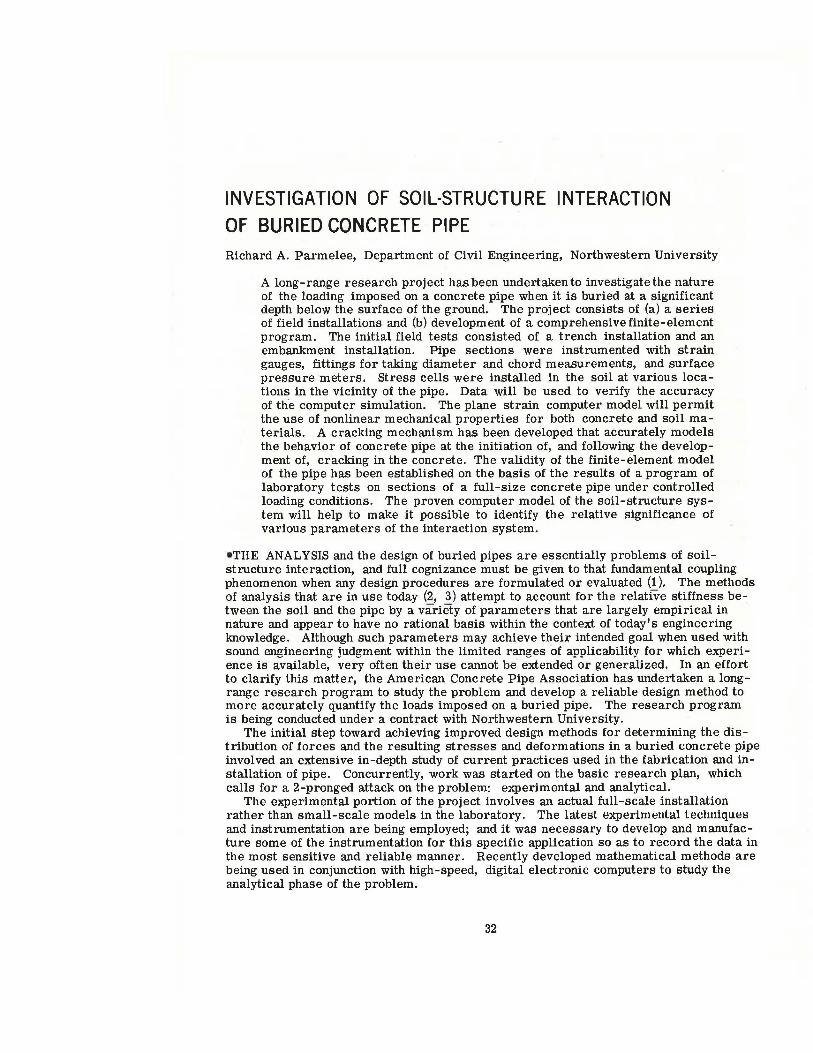
The overall plan for conducting the research program consists of 4 interdependent phases as shown in Figure 1. Phases I and III are primarily analytical, and phases II and IV provide the all-important interfacing with the results from full-scale testing programs.
The objective of phase I is the development of a theoretical mathematical model of a reinforced concrete pipe. That model is based on a plane strain, finite-element idealization in which the elements are quadrilateral and can have nonlinear material properties (4). The stress-str ain relation proposed by Hognestad (5) is used for the concrete elements. The model that was developed for phase I of the project will be described in a subsequent section of this paper.
In phase II the validity of this mathematical model of the pipe is established by comparison of the predicted response with data measured during full-scale testing of sections of pipe. The output of phase II will be a valid mathematical model that will accurately predict the behavior of a wide range of sites and classes of concrete pipe.
The soil parameters of the interaction system are the input for phase III. The material properties for the quadrilateral and triangular finite elements representing the soil will be nonlinear and will be established on the basis of an extensive laboratory testing program. The objective of this program will be to define the types of simplified tests that are necessary to perform on any soil to evaluate appropriate material properties to be used for the finite-element idealization of the particular construction site under consideration.
In phase IV the adequacy of the finite-element program to simulate the measured behavior of various full-scale installations will be investigated. The results from the full-scale tests will be considered as the "exact solution" to the problem, and they will serve as a basis for making suitable adjustments in the finite-element mathematical model in order that the 2 solutions will be in agreement. The end product of phase IV will be a valid mathematical model of a soil-pipe interaction system.
This model will make it possible to readily identify the relative significance of various parameters of the interaction of the system, such as nature and distribution of loading around the pipe, inherent structural strength of the pipe, influence of materials, and realistic factor of safety. Whenever possible, the results of recently developed innovations in the manufacture and installation of pipe will be included in the parametric studies undertaken during this phase of the program in order to check their overall effect on the soil-pipe system.
Based on the information generated from detailed study, interpretation, and evaluation of the significant parameters, a set of rational design approaches for concrete pipe will be developed. The resulting design method will be aimed toward permitting the accurate prediction of the distribution of forces on the buried pipe and of the factor of safety against each possible mode of failure from a knowledge of the measurable properties of the pipe, bedding, and fill material.
FULL-SCALE INSTALLATION
Two full-scale installations of instrumented sections of concrete pipe were completed during the initial year of the project. Each of the installations is identical with respect to the size and class of pipe and also the height of fill. The major difference between the test sites is that one pipe system was constructed as an embankment installation and the other as a trench installation. The pipe size is 60 in., and the height of fill is 25 ft.

34
Studies of the effects of shallow fill heights or live loading or both will be considered in detail during later phases of the project.
The full-scale concrete pipe test installations are located at the Transportation Research Center (TRC) in East Liberty, Ohio (approximately 50 miles northwest of Columbus). The embankment test pipe is part of a utility tunnel under the 71/z-mile oval that is being constructed as the center's high-speed test track. The trench test pipe is a "blind" installation located in a corn field in a remote area on the campus; no proposed facility at the center afforded the required depth of cover.
The pipe for each installation was designed on the basis of current design methods (using Marston-Spangler criteria), and a class B bedding was assumed for both the trench and the embankment conditions. All sections of the test pipe (five per installation) were manufactured by means of the wet-casting process, and standard production techniques were employed to ensure that the units would be representative of typical concrete pipe as fabricated for today's market.
The installation of the pipe sections was accomplished through a change order on an existing contract at the TRC; that contract was under the jurisdiction of the Ohio Department of Highways. The pipe sections were installed in accordance with the standard specifications of the Ohio Department of Highways, and the construction sequence was inspected by representatives from the highway department. Thus, the pipe was installed by contractors who used equipment and procedures that are used on typical construction jobs, and the research team did not exercise any control over the installation techniques.
Therefore, each installation can be considered to be representative of an average buried pipeline as constructed today. The data from those test sites will provide valu,.able insight into the true behavior of buried concrete pipe, and the important effect of soil-structure interaction can be studied. Data will be obtained from those installations for at least 3 years so that the influence of time effects on the behavior of the systems can be evaluated.
Both installations were instrumented in a similar manner. Three types of instrumentation were affixed to the pipe sections: strain gauges, diameter- and chordmeasuring devices, and pressure cells mounted flush with the outside surface of the pipe.
The strain gauges are located at points every 22 1h deg around the circumference of the pipe. Those gauges are positioned at 4 points through the thickness of the pipe: on the inside surface of the concrete, on the circumferential reinforcement of the inner cage, on the circumferential reinforcement of the outer cage, and on the exterior surface of the concrete. In addition, strain gauges have been applied in a longitudinal configuration at several locations along the length of each test site.
Reference points are located at 45-deg intervals around the pipe sections in order that diameter a.'ld chord measurements can be made between the points. That arrangement makes it possible to monitor the changes that occur in the internal geometry of the pipe during the backfilling operation and with respect to time.
The pressure cells on the exterior surface of the pipe are 6 in. in diameter and measure the total normal stress at the soil-pipe interface. Cells of a similar design, but 10 in. in diameter, are buried at various locations in the soil in the vicinity of the pipe and also in the "free-field."
Soil settlement plates were installed at various positions in close proximity to the pipe and also at different elevations of the backfill. During the backfilling operation, numerous soil samples were taken, and an extensive laboratory testing program of those samples is now nearing completion.
Readings were taken of all the instrumentation at various heights of fill during the backfilling operations. Those data were then analyzed by means of statistical techniques, and the results will be used in conjunction with the finite-element computer simulation to construct mathematical models of the soil-structure system at each test site.
The actual construction sequence for each site will be simulated on the computer by means of solving the appropriate finite-element model for each step of the process (i.e., preparation of the site, placement of bedding, installation of the pipe, and layer-bylayer sequence of backfilling). The data from the solution at each step will be compared
35
with the corresponding quantities from the analysis of the experimental data. Such a comparison will make it possible to introduce appropriate corrections to the input parameters for the soil-structure system such that the output from the computer simulation agrees with the data from the "exact solution" (i.e., the results from the fullscale test).
FINITE-ELEMENT MODEL FOR REINFORCED CONCRETE PIPE
For proper analysis of the behavior of buried concrete pipe, the pipe itself must be modeled in a way that takes into account the influence of progressive cracking of reinforced concrete. The phenomenon of progressive cracking has a significant effect on internal stresses and displacements as well as on external deflection of the pipe structure. Thus, it is imperative that the computer simulation of the soil-structure system be capable of modeling that very important aspect of the behavior of actual installations of buried concrete pipe. A major programming effort was necessary to properly incorporate the phenomenon of progressive cracking (and the subsequent changes in tne statics, geometry, and material properties) into the computer simulation of the pipe.
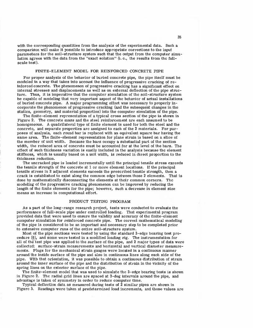
The finite-element representation of a typical cross section of the pipe is shown in Figure 2. The concrete mass and the steel reinforcement are each assumed to be homogeneous. A quadrilateral type of finite element is used for both the steel and the concrete, and separate properties are assigned to each of the 2 materials. For purposes of analysis, each round bar is replaced with an equivalent square bar having the same area. The finite-element representation for plane strain is based on a slice of the member of unit width. Because the bars occupy a substantial part of the section width, the reduced area of concrete must be accounted for at the level of the bars. The effect of such thickness variation is easily included in the analysis because the element stiffness, which is usually based on a unit width, is reduced in direct proportion to the thickness reduction.
The uncracked pipe is loaded incrementally until the principal tensile stress exceeds the tensile strength of the concrete at 1 or more element locations. If the principal tensile stress in 2 adjacent elements exceeds the prescribed tensile strength, then a crack is established to exist along the common edge between those 2 elements. That is done by mathematically disconnecting the elements at their common corners. The modeling of the progressive cracking phenomenon can be improved by reducing the length of the finite elements for the pipe; however, such a decrease in element size means an increase in computational effort.
PRODUCT TESTING PROGRAM
As a part of the long-range research project, tests were conducted to evaluate the performance of full-scale pipe under controlled loading. That experimental program provided data that were used to ensure the validity and accuracy of the finite-element computer simulation for reinforced concrete pipe. The correct mathematical modeling of the pipe is considered to be an important and necessary step to be completed prior to extensive computer runs of the entire soil-structure system.
Most of the pipe sections were tested by using the standard 3-edge bearing test procedure (6), and some were tested in a modified loading rig. The instrumentation for all of the test pipe was applied to the surface of the pipe, and 2 major types of data were collected: surface-strain measurements and horizontal and vertical diameter measurements. Plugs for the mechanical strain gauges were located in a continuous manner around the inside surface of the pipe and also in continuous lines along each side of the pipe. With that orientation, it was possible to obtain a continuous distribution of strain around the inner surface of the pipe and the distribution of strain in the vicinity of the spring lines on the exterior surface of the pipe.
The finite-element model that was used to simulate the 3-edge bearing tests is shown in Figure 2. The radial grid lines are spaced at 3-deg intervals around the pipe, and advantage is taken of symmetry in order to reduce computer time.
Typical deflection data as measured during tests of 2 similar pipes are shown in Figure 3. Readings were taken at predetermined load increments, and those values are
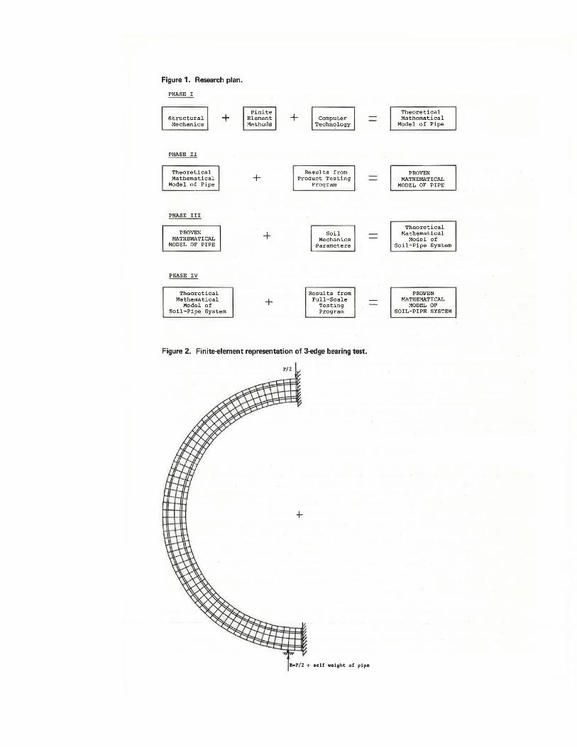
Figure 1. Research plan.
Structural Mechanics
PHASE II
Theoretical Mathematical
Model of Pipe
PHASE III
PROVEN MATHEMATICAL
MODEL OF PIPE
Pt!ASE IV
Theoretical Mathematical
Model of
+
Soil-Pipe System
Finite Element MP.thods
+
+
+
+ Computer Techn~logy
Results from Product Testing
Program
Soil Mechanics
Parameters
Results from Full-Scale
Testing Program
Figure 2. Finite-element representation of 3-edge bearing test.
R•P/2 + oelf wei1ht of pipe
Theoretical Mathematical
Model of Pipe
PROVEN MATHEMATICAL
MODEL OF PIPE
Theoretical Mathematical
Model of Soil-Pipe System
PROVEN MATHEMATICAL
MODEL OF SOIL-PIPE SYSTEM

Figure 3. Measured and predicted deflection changes of 60-in. pipe.
0.20 Pipes Nos. 3 and 4, Class IV
0.15
0.10 Horizontal DiametP cracking at spt'ingline
0 0.05 ~ .c
v
~ at invert
~ .. " o.oo . .c " 60 70 BO .. ~ Total Load on Pipe (kips) ~
! -0.05 "' Vertical Diameter
-0.10
----t:r- Pipe No.
-D- Pipe No, 4 ·0.15 -·- Computed
-0.20
Figure 4. Mixed-element representation of 3-edge bearing test.
P/2
f R•P/2 + self weight of pipe

38
recorded as either triangles or squares in the figure. The data points have been connected with straight lines to denote the progression of deflection with applied load. The load increments at which surface cracking was initially observed are also noted.
The predicted deflection behavior of the mathematical model of a pipe having properties equivalent to the actual pipe are shown as solid circles. Sketches showing the extent of cracking in the model at various loading stages are presented in the lower portion of the figure.
The agreement between the actual and the predicted values of deflection is very good, and similar correlations were obtained for the strain data around the surface of the pipe and also for the changes in geometry the pipe experienced throughout the loading cycle. The computer simulation of the concrete pipe was judged to be very satisfactory for all of the specimens tested, regardless of the size of the pipe, amount of reinforcement, or method of loading.
There is a difficulty in using the 3-deg-element mesh to model the buried pipe because of the large number of elements and node points required. Therefore, the model was modified to reduce the number of nodes and elements. The grid developed is shown in Figure 4. The elements are a mixture of 3-, 6-, and 9-deg elements. The smaller elements are located at positions where the previous analyses indicated cracking will occur. The response of this model for the concrete properties and loading of the previous analysis compared with the response of the 3-deg model is shown in Figure 5. Generally the mixed-element model is a good approximation of the 3-deg-element model for the same concrete properties and loading, and it requires much less computer time. Thus, the mixed-element grid is the mathematical model for the pipe and will be used in the computer simulation of the buried pipe system; that represents the completion of phase II (Fig. 1).
Figure 5. Comparison of computer simulations for tests 3 and 4 using 3-deg- and mixed-element models.
0.20
0.15
0.10 Horizontal Diameter
m 0.05 . "' u
~ • .. 0 o.oo • ..: 50 60 70 u
BO 90
" • Total Load on Pipe (kips)
j -0.05 0
Vertical Diameter -0.10
_ ..,._ - 3° Element Model
-0.15 ---'\'}--- Mixed Element Model
-0.20

39
SOIL MECHANICS PARAMETERS
The results of a few preliminary analyses of the full-scale test installations have shown that extreme care must be taken in defining the nonlinear material properties of the soil surrounding the pipe. The necessary theoretical development and associated laboratory testing program for establishing the appropriate input for phase III of the overall program are currently in progress. Those parameters will be incorporated into the computer simulation as soon as they have been evaluated and verified.
CONCLUSION
In general, all of the previous full-scale investigations of buried concrete pipe have recorded only the gross behavior of the pipe itself. In contrast, the present investigation is the most extensive testing program yet undertaken for concrete pipe, and it is the first field study to consider the interaction behavior of the total soil-structure system. A wealth of data have been and will be obtained from the 2 test sites, and all of it will be most useful in assessing the present state of the art in the design, fabrication, and installation of buried concrete pipe.
With the aid of the computer-simulated, finite-element model of the soil-structure system and the data from the full-scale installations, it will be possible to properly evaluate and quantify the degree of accuracy of existing design procedures for buried concrete pipe. The finite-element model will be used to make extensive parametric studies of the composite soil-structure system and investigate the factors influencing the behavior of buried concrete pipe. Those data will make it possible to propose modifications of current design methods or to develop new design procedures, fabrication techniques, and installation methods. Any recommendations will be tested in additional full-scale installations to be carried out in the remaining years of the research program. The ultimate objective of this long-range investigation will be the development of a design tool that will be realistic, yet simple and easy to use.
REFERENCES
1. Krizek, R. J., Parmelee, R. A., Kay, J. N., and Elnaggar, H. A. Structural Analysis and Design of Pipe Culverts. NCHRP Rept. 116, 1971.
2. Spangler, M. G. The Supporting strength of Rigid Pipe Culverts. Eng. Exp. Station, Iowa state College, Bull. 112, 1933.
3. Concrete Pipe Design Manual. American Concrete Pipe Assn., Arlington, Va., 1970. 4. Wilson, E. L. Users Manual for a General Purpose Finite Element Program for the
Analysis of Plane strain structures. Div. of struct. Eng. and Struct. Mech.; Univ. of California, Berkeley, 1967.
5. Hognestad, E. A Study of Combined Bending and Axial Load in Reinforced Concrete Members. Eng. Exp. Station, Univ. of Illinois, Urbana, Bull. 399, 1951.
6. standard Methods of Test for Determining Physical Properties of Concrete Pipe or Tile. ASTM, standard C 497, 1970.