investigation of stress and failure in granular soils … · • aspect ratio influence was not...
TRANSCRIPT

UNCLASSIFIED
UNCLASSIFIED
INVESTIGATION OF STRESS AND FAILURE IN GRANULAR SOILS
FOR LIGHTWEIGHT ROBOTIC VEHICLE APPLICATIONS
Carmine Senatore*, Markus Wulfmeier†, Jamie MacLennan**, Paramsothy Jayakumar**, and Karl Iagnemma*
* Massachusetts Institute of Technology, Cambridge, MA, USA
† Gottfried Wilhelm Leibniz Universität Hannover Hannover, Germany
** U.S. Army TARDEC Warren, MI, USA
7 August 2012
UNCLASSIFIED: Distribution Statement A. Approved for public release.

Report Documentation Page Form ApprovedOMB No. 0704-0188
Public reporting burden for the collection of information is estimated to average 1 hour per response, including the time for reviewing instructions, searching existing data sources, gathering andmaintaining the data needed, and completing and reviewing the collection of information. Send comments regarding this burden estimate or any other aspect of this collection of information,including suggestions for reducing this burden, to Washington Headquarters Services, Directorate for Information Operations and Reports, 1215 Jefferson Davis Highway, Suite 1204, ArlingtonVA 22202-4302. Respondents should be aware that notwithstanding any other provision of law, no person shall be subject to a penalty for failing to comply with a collection of information if itdoes not display a currently valid OMB control number.
1. REPORT DATE 02 AUG 2012
2. REPORT TYPE Briefing
3. DATES COVERED 01-07-2012 to 01-08-2012
4. TITLE AND SUBTITLE Investigation of Stress and Failure in Granular Soils for LightweightRobotic Vehicle Applications
5a. CONTRACT NUMBER
5b. GRANT NUMBER
5c. PROGRAM ELEMENT NUMBER
6. AUTHOR(S) Jamie MacLennan; Paramsothy Jaykumar; Carmine Senatore; Markus Wulfmeier
5d. PROJECT NUMBER
5e. TASK NUMBER
5f. WORK UNIT NUMBER
7. PERFORMING ORGANIZATION NAME(S) AND ADDRESS(ES) Massachusetts Institute of Technology,77 Massachusetts Ave,Cambridge,Mi,02139
8. PERFORMING ORGANIZATIONREPORT NUMBER ; #23231
9. SPONSORING/MONITORING AGENCY NAME(S) AND ADDRESS(ES) U.S. Army TARDEC, 6501 East Eleven Mile Rd, Warren, Mi, 48397-5000
10. SPONSOR/MONITOR’S ACRONYM(S) TARDEC
11. SPONSOR/MONITOR’S REPORT NUMBER(S) #23231
12. DISTRIBUTION/AVAILABILITY STATEMENT Approved for public release; distribution unlimited
13. SUPPLEMENTARY NOTES Submitted to 2012 NDIA Ground Vehicle Systems Engineering and Technology Symposium August 14-16Troy, Michigan
14. ABSTRACT Gain deeper understanding of fundamental mechanics governing traction generation under small,lightweight vehicles.
15. SUBJECT TERMS
16. SECURITY CLASSIFICATION OF: 17. LIMITATION OF ABSTRACT
Public Release
18. NUMBEROF PAGES
20
19a. NAME OFRESPONSIBLE PERSON
a. REPORT unclassified
b. ABSTRACT unclassified
c. THIS PAGE unclassified
Standard Form 298 (Rev. 8-98) Prescribed by ANSI Std Z39-18

UNCLASSIFIED
UNCLASSIFIED
Motivation
• Gain deeper understanding of fundamental mechanics
governing traction generation under small, lightweight
vehicles.
• Improve modeling accuracy and predictive power.
• This will allow small robots to be more effective performers
and operate more reliably.
7 August 2012 2

UNCLASSIFIED
UNCLASSIFIED
Methodology
7 August 2012 3
Soil Characterization
Single Wheel
Experiments
Terramechanics Modeling
Direct Shear Tests
Penetration Tests
Interfacial Stress
Measurement
Soil Motion
Measurement (PIV)
Radius = 13 cm
Width = 16 cm Traction
1 0 Slip

UNCLASSIFIED
UNCLASSIFIED
Presentation Outline
• State-of-the-art model for wheeled vehicles mobility.
• Soil characterization (i.e., how to obtain the parameters
for the aforementioned model).
• Single wheel experimental methodologies
– Particle Image Velocimetry
– Force sensors
• Comparison between State-of-the-art modeling and
measurements
• Conclusions and future work
7 August 2012 4

UNCLASSIFIED
UNCLASSIFIED
Bekker-Wong Model
5
• Terramechanics models are based on: – Bekker-Wong equations for normal stress calculations
– Janosi-Hanamoto equation for tangential stress calculation
θ
θ Mohr-Coulomb criterion
σn =
σ1 =kcb+ kϕ r
n cos θ − cosθf𝑛 θm< θ < θf
σ2 =kcb+ kϕ r
n cos θf −θ − θbθm − θb
θf − θm − cosθf
𝑛
θb< θ < θm
𝑟
𝑟
𝜃𝑓
𝜃𝑓
Wong, J. Y., and Reece, A. R., “Prediction of rigid wheel performance based on the analysis of soil-wheel stresses part I,” Journal of
Terramechanics, Vol. 4, No. 1, pp. 81-98, 1967.
𝜃𝑚 is the angle where
normal stress reaches a
peak

UNCLASSIFIED
UNCLASSIFIED
Soil Characterization
Direct Shear Test
• Direct shear tests are used to characterize shearing
properties of soils
• Direct shear tests are standard tests in the geotechnical
practice
7 August 2012 6
Load
Cell
Motor drives at
constant
displacement rate

UNCLASSIFIED
UNCLASSIFIED
Direct Shear Test Results
• Direct shear tests provide shearing properties of the soil:
7 August 2012 7
Shear Modulus
Cohesion
Angle of Internal Friction
𝜏 = 𝑐 + 𝜎 tan 𝜙

UNCLASSIFIED
UNCLASSIFIED
Soil Characterization
Penetration Tests
• Plate penetration tests were
performed to characterize soil
response to normal loading
• According to Bekker-Wong
theory, plates dimension have to
be comparable with the wheel
contact patch under
investigation.
7 August 2012 8
Actuator
Encoder
Force
Sensor
Penetration
Plate
𝑧
𝑝

UNCLASSIFIED
UNCLASSIFIED
Penetration Tests
• Penetration tests provide information about soil normal loading response
7 August 2012 9
Frictional dependent soil coefficient Cohesion dependent soil coefficient
Sinkage exponent
0 10 20 30 40 50 60 70-2
0
2
4
6
8
10
12
14
16Pressure-Sinkage, All Trials
Sinkage [mm]
Pre
ssur
e [P
a x
104 ]
3-cm
5-cm
7-cm
160 mm
Plate width

UNCLASSIFIED
UNCLASSIFIED
Penetration Tests Variability
• Penetration tests showed how variable, even under carefully controlled laboratory
conditions, soil response can be.
• An initial attempt to statistically characterize soil response was made but further
investigations are under way.
• Aspect ratio influence was not investigated because plate width is constrained by
wheel geometry (wheel width is fixed while contact patch length depends on
sinkage).
• Using the (deterministic) approach suggested by Wong*, two sets of parameters
were calculated. 57 is obtained truncating the data at 50kPa.
10
0 10 20 30 40 50 60 70-2
0
2
4
6
8
10
12
14
16Pressure-Sinkage, All Trials
Sinkage [mm]
Pre
ssure
[P
a x
10
4]
Set n 𝑘𝑐 [kN/mn+1] 𝑘𝜙 [kN/mn+2]
357 0.99 -55 4584
57 1.4 846 6708 3-cm
5-cm
7-cm
* Wong, J.Y., “Data processing methodology in the characterization of the mechanical properties of terrain,” Journal of
Terramechanics, 17(1):13 – 41, 1980.

UNCLASSIFIED
UNCLASSIFIED
Single Wheel Testbed
11 11
Vertical
load
control 6-axis
F/T
Sensor
Mars Soil
Simulant*
* L. W. Beegle et al., “MOJAVE MARTIAN SIMULANT: A NEW MARTIAN SOIL SIMULANT,” Lunar and Planetary Science, XXXVIII, 2007
Torque
sensor
Draw-wire encoder
for sinkage
measurement
A motor drives
the horizontal
carriage.
A motor
drives the
wheel

UNCLASSIFIED
UNCLASSIFIED
PIV Setup
7 August 2012 12
Tempered 1”
Thick Glass
500W
Spot
Lights
Phantom 7.1 High Speed Camera
Ruler,
needed to
calibrate
pixel/mm
ratio
B~T!-----------GVSETS

UNCLASSIFIED
UNCLASSIFIED
PIV Description
• PIV is a methodology for extracting instantaneous velocity
fields from a series of images
• Probable displacement is determined by using the cross
correlation function
13
𝑅𝑢(𝑥, 𝑦) = 𝐼1 𝑖, 𝑗 𝐼2(𝑖 + 𝑥, 𝑗 + 𝑦)
𝐿
𝑗=−𝐿
𝐾
𝑖=−𝐾
Adrian, R. J., and Westerweel, J., Particle Image Velocimetry, Cambridge University Press, New York, 2011

UNCLASSIFIED
UNCLASSIFIED
PIV Validation
• Since a ground truth for soil motion was not available,
the velocity of a plate (precisely measured through a
draw-wire encoder) was compared with PIV
measurements.
7 August 2012 14
0 0.4 0.8 1.20
0.002
0.004
0.006
0.008
0.01
0.012
0.014
Time [s]
Velo
city [m
/s]
String Potentiometer (LabView)
Moving Mask - IW size 16
UNCLASSIFIED
UNCLASSIFIED
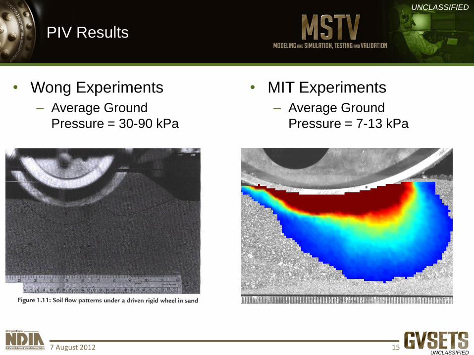
PIV Results
• Wong Experiments
– Average Ground
Pressure = 30-90 kPa
7 August 2012 15
• MIT Experiments
– Average Ground
Pressure = 7-13 kPa

UNCLASSIFIED
UNCLASSIFIED
Force Sensors
• Flexing beam instrumented with strain gauges
• Tangential and Normal forces applied to the tip can be
reconstructed from gauges reading
7 August 2012 16
𝑁
𝑇
𝑇𝑑1
𝑇 𝑑1 +𝑁 𝑑2
𝑑1
𝑑2
Gauge
Gauge
𝜔
𝜎 𝜏

UNCLASSIFIED
UNCLASSIFIED
Stress Profile at Wheel-Soil
Interface for Low Slip
7 August 2012 17
0 5 10 15 20 25 300
10
20
30
40
50
Norm
al S
tress -
[
kP
a]
0 5 10 15 20 25 30-6
-4
-2
0
2
4
Central Angle [deg]
Tangential S
tress -
[
kP
a]
0 5 10 15 20 25 300
10
20
30
40
Norm
al S
tress -
[
kP
a]
0 5 10 15 20 25 30-20
-15
-10
-5
0
Central Angle [deg]
Tangential S
tress -
[
kP
a]
-10% slip +10% slip
5 10 15 20 25 30 350
5
10
15
20
Norm
al S
tress -
[
kP
a]
I - Inner
II
III
IV
V
5 10 15 20 25 30 35-20
-15
-10
-5
0
Central Angle [deg]
Tangential S
tress -
[
kP
a]

UNCLASSIFIED
UNCLASSIFIED
Stress Profile at Wheel-Soil
Interface for High Slip
7 August 2012 18
5 10 15 20 25 30 35 40 45-10
0
10
20
30
40
Norm
al S
tress -
[
kP
a]
I - Inner
II
III
IV
V
5 10 15 20 25 30 35 40 45-5
0
5
10
Central Angle [deg]
Tangential S
tress -
[
kP
a]
5 10 15 20 25 30 350
5
10
15
20
Norm
al S
tress -
[
kP
a]
I - Inner
II
III
IV
V
5 10 15 20 25 30 35-20
-15
-10
-5
0
Central Angle [deg]
Tangential S
tress -
[
kP
a]
-70% slip +70% slip

UNCLASSIFIED
UNCLASSIFIED Comparison Between Bekker-
Wong Model and Measured
Stress
7 August 2012 19
-10 -5 0 5 10 15 20 250
10
20
30
40
Norm
al S
tress -
[
kP
a]
-10 -5 0 5 10 15 20 25-15
-10
-5
0
Central Angle [deg]
Tangential S
tress -
[
kP
a]
I - Inner
II
III
IV
V
Model 357
Model 57
-10 -5 0 5 10 15 20 250
10
20
30
40
Norm
al S
tress -
[
kP
a]
-10 -5 0 5 10 15 20 25-15
-10
-5
0
Central Angle [deg]
Tangential S
tress -
[
kP
a]
Set n 𝑘𝑐 [kN/mn+1]
𝑘𝜙 [kN/mn+2]
357 0.99 -55 4584
57 1.4 846 6708
+10% slip +30% slip
0 10 20 30 40 50 60 70-2
0
2
4
6
8
10
12
14
16Pressure-Sinkage, All Trials
Sinkage [mm]
Pre
ssur
e [P
a x
104 ]
3-cm
5-cm
7-cm

UNCLASSIFIED
UNCLASSIFIED
Conclusions and Future Work
• PIV shows phenomena that do not completely agree with
assumptions behind classical models
– Only one failure envelope develops (not two)
– Soil failure is periodic
– Soil is always attached to the wheel surface
• However, stress measurements show that Bekker-Wong
model is still able to capture main trends (for low slip).
• Further efforts will be dedicated to characterize variability
in soil response and how models are affected by it.
• The underlying complex mapping between soil
displacement and stress (i.e., constitutive law) will be
investigated in order to improve modeling capabilities.
7 August 2012 20