investigation of the cup drawing process from a …
TRANSCRIPT
IJREAT International Journal of Research in Engineering & Advanced Technology, Volume 9, Issue 3, June- July, 2021 ISSN: 2320 – 8791 (Impact Factor: 2.317) www.ijreat.org
www.ijreat.org Published by: PIONEER RESEARCH & DEVELOPMENT GROUP (www.prdg.org) 47
INVESTIGATION OF THE CUP DRAWING PROCESS FROM A
NUMERICAL AND EXPERIMENTAL POINT OF VIEW Mr. C. Ravi Naik1, Mr. Joel2, Mr. Ravi Raj3
1Department of Mechanical Engineering, CMR Engineering College, kandlakoya, Medchal, Hyderabad, Telangana,
.
Abstract—The cup drawing processing of thin sheet plate takes an important surface place in forming metals on
account of large of number of industries applications of such products. The traditional techniques of tool design for
sheet forming operations used in industry are experimental and expensive. The cup drawing process is more
complicated than most other metal forming operations. Hence a rigorous study was performed to understand the
process. An extensive literature survey was performed and critical parameters affecting the process were identified.
Die design calculations were done to produce sample cups. Die, Punch and blank holder were fabricated according
to this design. The die set was then used to obtain cups from Al 1100, copper and Brass taking the help of a UTM
and noting the load pattern. Finite Element Simulation of the cup drawing processing using ANSYS 15.0 was also
carried with the actual dimensions and properties that have been used in experimentation. Plane185, a four noded
element was used to discretize the model. The Die, Punching and Blanking holder were treated to be rigid.
Axisymmetric condition was applied. Blank material was treated as a mild work hardening type. Load variation
with punch travel, Stress pattern in the blank over different stages, thickness changes in the cup bottom and walls
were analysed. Those results were found to be appropriate. The loads obtained are in close agreement with
experimental values. Hence the simulation performed with material data, friction conditions and rate of loading are
realistic. This work would definitely serve as a start up for tool designer and manufacturer doing work in this field.
Keywords- Cup Drawing Process, ANYSYS 15.0, UTM.
INTRODUCTION
In the various industrial application and automotive fields 85% of all metal is processed through so called casting
operation to obtain products in simple forms like ingots and slabs, and these products are then used for further
deformation operations. In manufacturing the deformation processes can be divided into groups depending on
temperature, shape and size of the used work pieces and operation type. For example, there are three categories of
processes based on temperature as a criterion, which are cold, warm and hot working. In dependence on the type of
the deformation operation, the processes can be also classified as primary and secondary working. Primary working
operations include taking pieces of metallic products that are generally in a cast state, and then they can be formed
into other shaped parts such as slabs, plates and billets. Additional processing can be performed on some of those
products through secondary working to produce the final shape of desired components such as bolts, sheet metal
parts and wire.
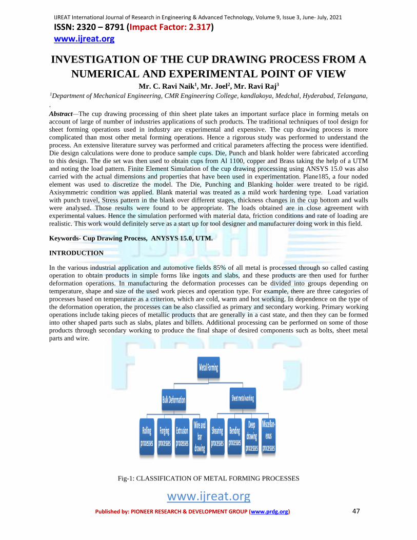
Fig-1: CLASSIFICATION OF METAL FORMING PROCESSES

IJREAT International Journal of Research in Engineering & Advanced Technology, Volume 9, Issue 3, June- July, 2021 ISSN: 2320 – 8791 (Impact Factor: 2.317) www.ijreat.org
www.ijreat.org Published by: PIONEER RESEARCH & DEVELOPMENT GROUP (www.prdg.org) 48
A. Sheet Metal Forming Processes
Sheet metal working can be generally identified by cutting and forming operations performed on metallic sheets. In
order to distinguish between the terms “sheet” and “plate”, it is important to realize that the range of sheet thickness
is typically from 0.4mm to 6mm, while the term plate usually refers to the product of thickness greater than 6mm.
The work metal used in sheet metal forming, whether sheet or plate is produced by rolling, hence
the significant importance of sheet metal forming outlines the importance of the rolling process. Traditionally sheet
is available as coils if it is thin; otherwise it is supplied as flat sheet or plate. Sheet metal parts are utilized in
different industrial applications such as automobile and truck bodies, aircraft, railway cars, farm and construction
equipment, beverage cans, kitchen utensils, etc.
Fig-2 AUTOMOTIVE PARTS PRODUCED BY SHEET METAL FORMING
B.Cup Drawing Process
One of the most common and industrial applicable processes in sheet metal forming is cup drawing. It can fabricate
a variety of objects with cylindrical, square or even complex shapes by using this technique. Cup drawing is defined
as a manufacturing process through which a sheet metal work piece is subjected to tensile and compressive stresses
by mechanical punch to press the blank into a die cavity as seen in Figure. The condition of the product to be deep
drawn is that the final depth is greater than a half of the drawing punch diameter; otherwise the product is classified
as a shallow part. In order to prevent the material blank from flowing freely into the die cavity through the process, a
third forming tool, which is named blank holder, is employed to hold down the blank . This technique can be widely
applied to manufacture metal products with an aspect ratio larger than unity. Currently, the deep drawing process
has an extensive role in aerospace and automobile industries to manufacture structural components, and in computer
and communication industries to produce covers and thin-walled part of devices, like laptop, cameras, and CD and
DVD drivers. In addition, it is used in fabricating aluminium cans, canisters, sinks, baking pans, oil filters, home
décor, etc.
In the Cup drawing technique, the flat piece obtained from a large sheet metal is named blank which is usually
clamped on the top surface of the forming die by means of a rigid tool conventionally called blank-holder. In order
to obtain a symmetric shape for a defects- free product, the centre point of the blank should coincide exactly with the
centre of the die opening. In general, two main resources contribute in providing the force needed to form the sheet
metal blank completely. The first force is that used to hold the sheet in contact with the upper surface of the die.
This force is known as the blank holding force because it is applied through the blank holder to catch the blank. The

IJREAT International Journal of Research in Engineering & Advanced Technology, Volume 9, Issue 3, June- July, 2021 ISSN: 2320 – 8791 (Impact Factor: 2.317) www.ijreat.org
www.ijreat.org Published by: PIONEER RESEARCH & DEVELOPMENT GROUP (www.prdg.org) 49
other one is provided by the punch. The function of the punch force is to form the blank into the die cavity.
Therefore, consequently the main tools required in deep drawing process are a male punch, a female die and a blank
holder plate. Usually between the sides of the drawing punch and die, a particular clearance is embraced and the
value of this clearance is about 10% greater than the original blank thickness.
Fig-2: SCHEMATIC ILLUSTRATION OF CUP DRAWING PROCESS
Figureshows simple cup drawing operation of a cylindrical cup with the basic parameters. A rigid punch with a
diameter (Dp) and nose radius (Rp) applies a drawing force (F) on a circular blank with initial diameter (Db) and
thickness (tb). Usually the blank is pressed into a die cavity with a corner radius (Rd) and is held down at the flange
porting by the blank holder force (Fh). It can be observed that if the corners of the forming punch are sharp (Rp and
Rd =0) then a cutting operation would be performed rather than a drawing operation. Also, it is essential to adopt a
clearance between the sidewalls of the punch and the die cavity. This clearance is usually about 10% greater than the
initial thickness of the blank used.
Fig-3:SCHEME OF CUP DRAWING PROCESS
DIE DESIGN
Die is very important part of drawing operation for drawing of the materials. so proper die design ,proper selection
of material for fabrication of die is done. In this chapter we design a die for circular cup. The blank used here for the
drawing is aluminium, copper, and brass materials. In order to prepare a die with good design, many variables are to
be considered such as the die should be dimensionally stable, variations in response to change in temperature need to
be minimum, strong and durable, withstand the loads and shocks, finishing procedures are economical and easy to
IJREAT International Journal of Research in Engineering & Advanced Technology, Volume 9, Issue 3, June- July, 2021 ISSN: 2320 – 8791 (Impact Factor: 2.317) www.ijreat.org
www.ijreat.org Published by: PIONEER RESEARCH & DEVELOPMENT GROUP (www.prdg.org) 50
use. Successful cup drawing depends on many factors. Ignoring even one of them during die design and building can
prove disastrous. However, regardless of the many factors involved, the most important element to a successful deep
drawing operation is initiating metal flow. The following are key elements affecting metal flow, and each of them
should be considered when designing, building, or troubleshooting deep drawing dies The cup drawing die is
designed for the shell shown in figure (Aluminium 1100, Copper and Brass blank materials)
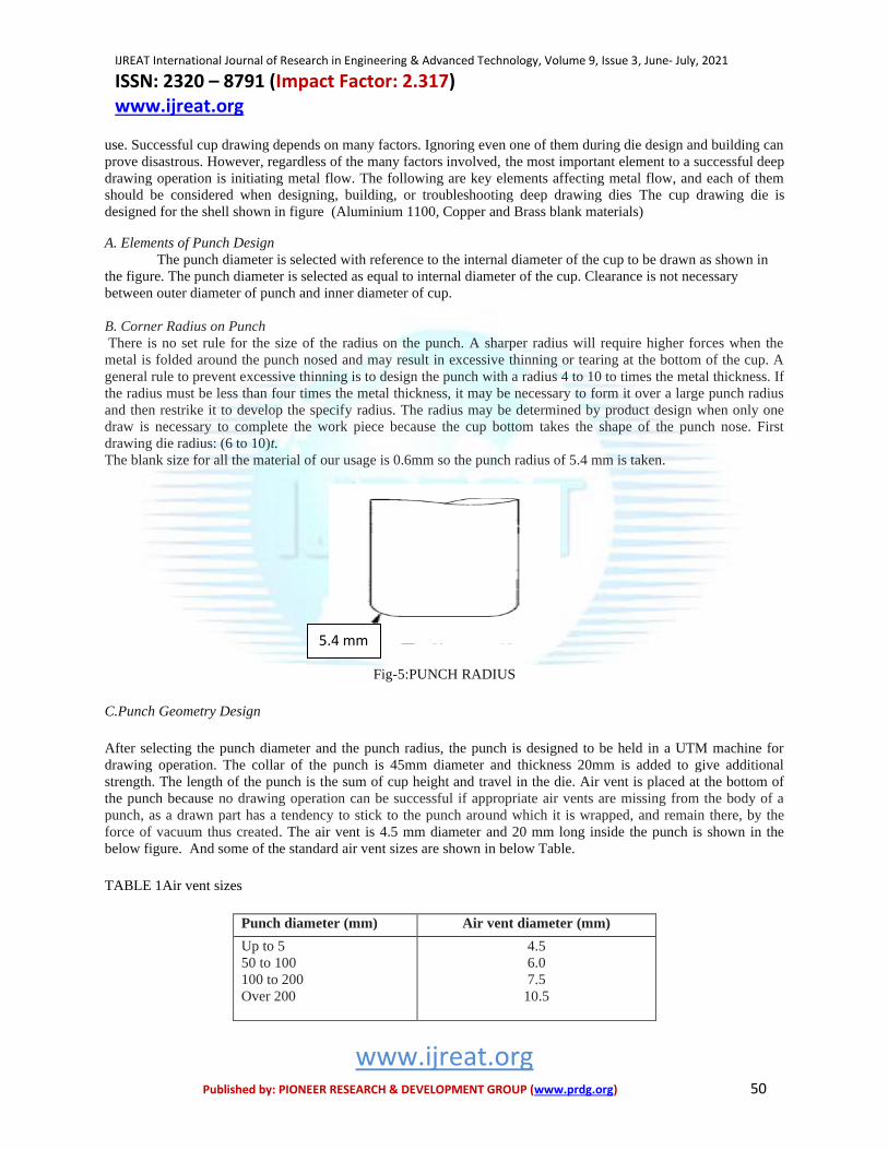
A. Elements of Punch Design
The punch diameter is selected with reference to the internal diameter of the cup to be drawn as shown in
the figure. The punch diameter is selected as equal to internal diameter of the cup. Clearance is not necessary
between outer diameter of punch and inner diameter of cup.
B. Corner Radius on Punch
There is no set rule for the size of the radius on the punch. A sharper radius will require higher forces when the
metal is folded around the punch nosed and may result in excessive thinning or tearing at the bottom of the cup. A
general rule to prevent excessive thinning is to design the punch with a radius 4 to 10 to times the metal thickness. If
the radius must be less than four times the metal thickness, it may be necessary to form it over a large punch radius
and then restrike it to develop the specify radius. The radius may be determined by product design when only one
draw is necessary to complete the work piece because the cup bottom takes the shape of the punch nose. First
drawing die radius: (6 to 10)t.
The blank size for all the material of our usage is 0.6mm so the punch radius of 5.4 mm is taken.
Fig-5:PUNCH RADIUS
C.Punch Geometry Design
After selecting the punch diameter and the punch radius, the punch is designed to be held in a UTM machine for
drawing operation. The collar of the punch is 45mm diameter and thickness 20mm is added to give additional
strength. The length of the punch is the sum of cup height and travel in the die. Air vent is placed at the bottom of
the punch because no drawing operation can be successful if appropriate air vents are missing from the body of a
punch, as a drawn part has a tendency to stick to the punch around which it is wrapped, and remain there, by the
force of vacuum thus created. The air vent is 4.5 mm diameter and 20 mm long inside the punch is shown in the
below figure. And some of the standard air vent sizes are shown in below Table.
TABLE 1Air vent sizes
Punch diameter (mm) Air vent diameter (mm)
Up to 5
50 to 100
100 to 200
Over 200
4.5
6.0
7.5
10.5
5.4 mm

IJREAT International Journal of Research in Engineering & Advanced Technology, Volume 9, Issue 3, June- July, 2021 ISSN: 2320 – 8791 (Impact Factor: 2.317) www.ijreat.org
www.ijreat.org Published by: PIONEER RESEARCH & DEVELOPMENT GROUP (www.prdg.org) 51
D.Elements of Die Design
The radius on the draw die (draw ring) does not contribute to the cup shape, so as large as possible to permit to full
freedom of metal flow as it passes over the radius. The draw ring causes the metal to being flowing plastically and
aids in compressing and thickening the outer portion of the blank. However, if the draw radius is too large the metal
will be released by the blank holder too soon and wrinkling will result. Too sharp a radius will hinder the normal
flow of the metal and cause uneven thinning of the cup wall, with resultant tearing. The general rule is to make the
draw radius four times the material thickness. The draw radius may be increased six to eight times the metal
thickness when drawing shallow cups of heavy-gauge metals without a blank holder
Draw radius = 4t
= 4 to 8t when the blank holder is used
In our design draw radius on die is taken as 4t .
Die Geometry
After selecting cup to be drawn andpunch geometry, die is designed. For this draw radius on die, die clearance is
selected from the above table according to the blank thickness. The height of the die is 40.5 mm and 75 mm
diameter. In this above the die 0.5 mm thick wall is created to place the blank. Die land 12 mm is taken according
the blank diameter.
E. Die- punch clearance
Die clearance is the gap left between the punch and die to allow for the flow of the work material. Generally
enough clearance is left to allow for thicking depending upon the type of operation and the metal. When clearance is
equal to the metal thickness or less, ironing or burnishing of the metal will occur near the top of the cup. A certain
amount of ironing may be allowable on the more ductile metals from the uniformity of wall thickness is required.
Thickness of the blank material is taken as 0.6mm for all the three material so the die clearance is chosen from the
below table 3-2 for the first draw as 1.08t – 1.1t
Table draw clearance
t = thickness of the original blank
TABLE 2: Die - Punch Clearance
Blank thickness,
mm
Die- Punch Clearance
First draws Redraws Sizing
draw
Up to 0.38
0.4-1.27
1.3 – 3.18
3.5 and Up
1.07t -1.09t
1.08t-1.1t
1.1t -1.12t
1.12t -.1.14t
1.08t-1.1t
1.09t-1.12t
1.12t-1.14t
1.15t-1.2t
1.04t – 1.05t
1.05t – 1.06t
1.07t – 1.09t
1.08t – 1.1t
F. Blank Size
One of the first jobs of the draw die designer is to find the size of the blank to be used to for making a given cup. It
is often difficult to find a blank of the exact size required for making a given shell, because of thinning and
thickening of sheet during drawing. The calculation could be based on the volume, surface area or by layout. The
following gives the useful relations in calculating the blank diameter for cylindrical shells for relatively thin
materials.𝐷 = √𝑑2 + 4𝑑ℎ
D = √𝑑2 + 4𝑑ℎ − 0.5𝑟
D = √𝑑2 + 4𝑑ℎ − 𝑟
D = √(𝑑 − 2𝑟)2 + 4𝑑(ℎ − 𝑟) + 2𝜋𝑟(𝑑 − 0.7𝑟)

IJREAT International Journal of Research in Engineering & Advanced Technology, Volume 9, Issue 3, June- July, 2021 ISSN: 2320 – 8791 (Impact Factor: 2.317) www.ijreat.org
www.ijreat.org Published by: PIONEER RESEARCH & DEVELOPMENT GROUP (www.prdg.org) 52
Where r = corner radius on the punch
h = height of the shell
d= outer diameter of the shell
D =blank diameter
In our case d/r is 6.5 and for this last formula is used to get the blank diameter D, some extra amount of blank
material was included to trim after the drawing operation. In our case d =36.6mm, h =14mm, r = 5.6mm, so a blank
diameter of 55mm was obtained.
G.Drawing Force
The amount of force required to shape a symmetrical cup by drawing operation plays a major role in design of
die elements. For the different material the drawing force may be vary. In our case aluminium, copper, and brass
blanks were used. The drawing force which is used for drawing cup is calculated by below formula.
𝑃 = 𝜋𝑑𝑡(𝑈𝑇𝑆)(𝐷
𝑑− 𝑐)
Where P = drawing pressure
D = shell OD
D= blank diameter
t = thickness of metal
UTS = Ultimate tensile strength
C= constant to cover friction and bending ( 0.6 to 0.7 for ductile materials)
The above formula is applicable to a symmetrical cupping operation only. The stretching and compression of metal
in irregular parts is too unpredictable for predicting forces by formula. However, the above formula may be used to
some extent in determining approximate forces for work pieces similar in configuration to a symmetrical cup.
The drawing force is computed from the above formula
TABLE 3
Material Draw Force
Tonnes
Aluminium 1100 drawing
force p
1.45
copper drawing force p is
tons
3.22
For brass drawing force p is
tons
3.66
H. Material Selection for Die Set
A valuable contribution to the successful drawing process is a properly selected die material. The choice is governed
mainly by the material strength for die, dimensional stability, variations in response to change in temperature need to
be minimum, strong and durable to withstand the designed forces and finishing procedures being economical and
easy to use. The material here selected is EN-8 steel. The strength of the EN-8 steel is more than the drawing
material. The cup work piece material arealuminium 1100, copper and brass.
FABRICATION OF DIE, PUNCH AND BLANK HOLDER

IJREAT International Journal of Research in Engineering & Advanced Technology, Volume 9, Issue 3, June- July, 2021 ISSN: 2320 – 8791 (Impact Factor: 2.317) www.ijreat.org
www.ijreat.org Published by: PIONEER RESEARCH & DEVELOPMENT GROUP (www.prdg.org) 53
EN-8 is used for preparation of Die, Punch and Blank holder. Material is drawn from our college work
shop with the dimensions of 50mm diameter and 90mm long bar which is used for preparation of Punch. EN-8 steel
of 80mm diameter and 100 mm long bar is taken for fabrication of Die and Blank holder.
EN-8 steel bar of 50mm diameter 90mm long bar is taken for manufacturing of Punch, three steps for
manufacturing of Punch i,e Facing, Turning, Finishing are carried out.
A.Steps Involved In Manufacturing of Die
There are five basic steps involved in manufacturing of Die.
1. Cutting
2. Facing
3. Turning
4. Drilling
5. Boring
6. Drilling and tapping
Fig-6:SCHEMATIC REPRESENTATION FOR MANUFACTURING OF DIE
Tapped holes
For the assembly of Die, Blank holder Tapped holes are to be present in the die and cylinder, for that we
are using vertical drilling machine. Tapped hole of size 0.5mm is drilled into the cylinder, Holes are kept at every
900 of the cylinder, there by 4 holes in the Die are drilled.
Finishing
In the above step, Die manufacturing is finished. For the drawing purpose high surface finish is required, low
friction should be there, Finishing is done with the help of emery paper. There by high surface finish is obtained.
The finished component is shown below figure.
FIG-7: DIE
B.Steps involved in manufacturing of Blank holder

IJREAT International Journal of Research in Engineering & Advanced Technology, Volume 9, Issue 3, June- July, 2021 ISSN: 2320 – 8791 (Impact Factor: 2.317) www.ijreat.org
www.ijreat.org Published by: PIONEER RESEARCH & DEVELOPMENT GROUP (www.prdg.org) 54
1. Facing
2. Turning
3. Drilling
Facing
After the work piece is cut into pieces by power saw, the surface finish of machined surface is not good, in
order to get good surface finish the surface is faced, after the facing is done for all the five pieces then they are sent
for the next process.
Turning
For the manufacturing of Blank holder, The above 80mm dia and 40mm long should be turned to 75mm dia and
20mm long. After the turning is finished then the machined work piece is sent to drilling section. Here Rough
turning is done.
Drilling
After the turning process is finished, the machined component is to be drilled, the drill bit used for drilling is
19.58mm dia drill bit. The drill should be kept for 20mm long. We require 20mm hole in the Blank holder , so we
have to go to the boring operation in order to enlarge the hole to 20mm diameter.
FIG.8: BLANK HOLDER
EXPERIMENTAL PROCEDURE
A. Blank preparation
To prepare blanks, sheets have been cut into square strips approximately 10 mm greater
than the required finish size. After that the squares were turned to make circular disks. This
ensured that any work hardening effects at the rim of the disk caused by cutting were
eliminated. A series of blanks with different material was produced 55mm diameter.
The material used in this study was aluminium 1100, copper and brass sheet with thicknesses of 0.6 mm and 55 mm
diameter which is shown in figure 6.1. For each material, specimens have been cut along sheet during its
manufacturing process.

IJREAT International Journal of Research in Engineering & Advanced Technology, Volume 9, Issue 3, June- July, 2021 ISSN: 2320 – 8791 (Impact Factor: 2.317) www.ijreat.org
www.ijreat.org Published by: PIONEER RESEARCH & DEVELOPMENT GROUP (www.prdg.org) 55
FIG-9: BLANK SHEET METALS ALUMINIUM, COPPER AND BRASS
B. Machine Setup
Experiments were carried out on a 1000-kN universal testing machine. Figureshows the cup drawing apparatus
which mainly consists of the punch and the die. The punch including a centering part. Centering part is used for
positioning the punch concentrically to the die opening to ensure uniform clearance between the punch and the die
aperture. The die consists of 11.5 mm land and 5.2 mm die radius. The die is mounted on the base of a hydraulic
press. However, punch mounted on the upper movable jaw of the universal testing machine. The die has long wall
which is larger than land to facilitate disposal of drawn cups. At the fixed jaw dial indicator is attached to note the
punch movements.
FIG-10: EXPERIMENTAL SETUP
The punch and die of EN-8 Steel were produced by lathe and other machining process.
The chemical and mechanical properties of the used materials are shown in appendix. To the punch and die no heat
treatment is applied, used in room temperature. All produced punches have flat heads with a profile radius of 5.6
mm, collar 20 mm and punch length 50 mm long. The die was designed to have two zones; the first zone is circular
land while the second is wall which diameter is more than the die inner diameter.
C. Drawing Procedure
After the machine setup is completed power on the universal testing machine. With the constant speed punch moves
downwards this is attached to the upper movable jaw. When punch touch the blank material load increases with
punch travel one by one mm down the movement can seen from the dial indicator. Loads are obtained from the
UTM. The punch through the die at the same time blank sheet wrap the die and it pushed toward down to from a cup
shape with circular blank sheet. Same procedure was followed to all the materials. The below figure shows the
finished cup

IJREAT International Journal of Research in Engineering & Advanced Technology, Volume 9, Issue 3, June- July, 2021 ISSN: 2320 – 8791 (Impact Factor: 2.317) www.ijreat.org
www.ijreat.org Published by: PIONEER RESEARCH & DEVELOPMENT GROUP (www.prdg.org) 56
RESULTS
The drawing of cups has been performed with three blank materials viz., Al 1100, Copper and Brass. Pictures below
show the cups at the end drawing process. They need further trimming for getting useful form.
FIG-11:DRAWN CUP FROM THE AL 1100, COPPER AND BRASS
Below show the load observed as the punch descends.
FIG-12(A) AL 1100 LOAD VS PUNCH TRAVEL ON EXPERIMENT
0
500
1000
1500
1 2 3 4 5 6 7 8
Load
Kg
Punch Travel mm
LOAD VS PUNCH TRAVEL
Measured onUTM
IJREAT International Journal of Research in Engineering & Advanced Technology, Volume 9, Issue 3, June- July, 2021 ISSN: 2320 – 8791 (Impact Factor: 2.317) www.ijreat.org
www.ijreat.org Published by: PIONEER RESEARCH & DEVELOPMENT GROUP (www.prdg.org) 57
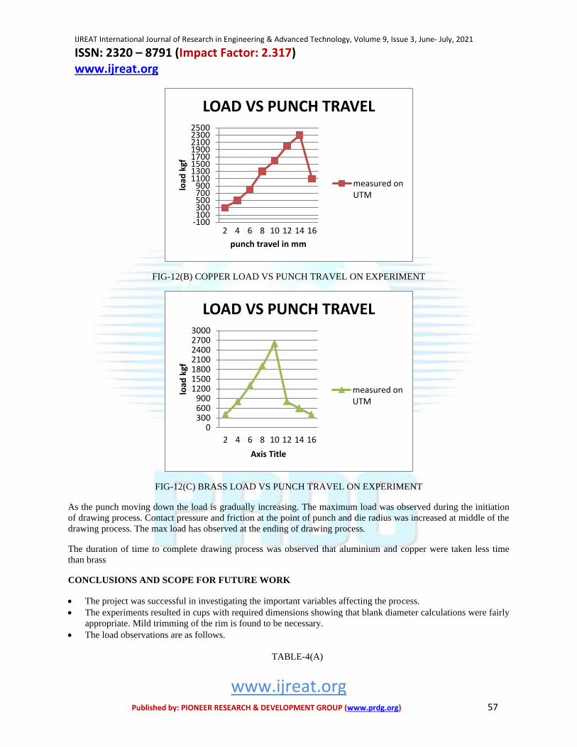
FIG-12(B) COPPER LOAD VS PUNCH TRAVEL ON EXPERIMENT
FIG-12(C) BRASS LOAD VS PUNCH TRAVEL ON EXPERIMENT
As the punch moving down the load is gradually increasing. The maximum load was observed during the initiation
of drawing process. Contact pressure and friction at the point of punch and die radius was increased at middle of the
drawing process. The max load has observed at the ending of drawing process.
The duration of time to complete drawing process was observed that aluminium and copper were taken less time
than brass
CONCLUSIONS AND SCOPE FOR FUTURE WORK
• The project was successful in investigating the important variables affecting the process.
• The experiments resulted in cups with required dimensions showing that blank diameter calculations were fairly
appropriate. Mild trimming of the rim is found to be necessary.
• The load observations are as follows.
TABLE-4(A)
-100100300500700900
11001300150017001900210023002500
2 4 6 8 10 12 14 16
load
kgf
punch travel in mm
LOAD VS PUNCH TRAVEL
measured onUTM
0300600900
1200150018002100240027003000
2 4 6 8 10 12 14 16
load
kgf
Axis Title
LOAD VS PUNCH TRAVEL
measured onUTM

IJREAT International Journal of Research in Engineering & Advanced Technology, Volume 9, Issue 3, June- July, 2021 ISSN: 2320 – 8791 (Impact Factor: 2.317) www.ijreat.org
www.ijreat.org Published by: PIONEER RESEARCH & DEVELOPMENT GROUP (www.prdg.org) 58
Range of Loads: Material – Al 1100
Minimum Load Maximum
Load
Using ANSYS 290kgf 960kgf
Using
Experiments
200kgf 1200kgf
TABLE-4(B)
Range of Loads: Material – Copper
Minimum
Load
Maximum
Load
Using
ANSYS
453kgf 1935kgf
Using
Experiments
300kgf 2300kgf
TABLE-4(C)
Range of Loads: Material – Brass
Minimum Load Maximum
Load
Using ANSYS 300kgf 2432kgf
Using
Experiments
400kgf 2600kgf
We find that the ANSYS predicted values are mildly under predicted (maximum of 16%). Future work needs to
bridge this mild gap. Since the sheet is generally rolled product, a degree of anisotropy would be responsible for
this.
• The punch travel Vs load pattern was observed to be similar in both ANSYS simulation and experiments.
• Thickness distribution is obtained by FEA & compared with work of other researchers.
• From the experimental results it observed that the load on aluminium material is smallest compared to the
same thickness of brass and copper sheet material.
• Lubricating effects need to be included.
• Temperature effects can be included.
REFERENCES
[1]. A. PourkamaliAnaraki, M. Shahabizadeh, and B. Babaee, rFinite Element Simulation of Multi-Stage Deep
Drawing Processes & Comparison with Experimental Results,World Academy of Science, Engineering and
Technology International Journal of Mechanical, Aerospace, Industrial, Mechatronic and Manufacturing
Engineering Vol:6, No:1, 2012.
[2]. Shishir Anwekar1, Abhishek Jain2, Finite Element Simulation of Single Stage Deep Drawing Process for
Determining Stress Distribution in Drawn Conical Component, International Journal Of Computational
Engineering Research (ijceronline.com) Vol. 2 Issue. 8, dec 2012
[3]. SusheelMadhavraoMagar, Mohan YashwantKhire, Deep drawing of cup shaped steel component: finite
element analysisand experimental validation,International Journal on Emerging Technologies 1(2): 68-
72(2010).
[4]. J. Pradeep kumar1, M. Bilal Tanveer2, Sagar.A. Makwana2, R. Sivakumar2, Experimental Investigation and
Optimization of Process Parameters on theDeep Drawing of AISI202 Stainless Steel, International Journal of
Engineering Research & Technology (IJERT), Vol. 2 Issue 4, April – 2013

IJREAT International Journal of Research in Engineering & Advanced Technology, Volume 9, Issue 3, June- July, 2021 ISSN: 2320 – 8791 (Impact Factor: 2.317) www.ijreat.org
www.ijreat.org Published by: PIONEER RESEARCH & DEVELOPMENT GROUP (www.prdg.org) 59
[5]. Najmeddin Arab1, AbotalebJavadimanesh, Theoretical and Experimental Analysis of Deep Drawing
Cylindrical Cup, Journal of Minerals and Materials Characterization and Engineering, 2013, 1, 336-342,
Published Online November 2013
[6]. SaaniShakil, MostafaHamed, AbdessalemChamekh, Single Stage Steel Cup Deep Drawing Analysis
using Finite Element Simulation, International Journal of Engineering Research & Technology (IJERT), Vol. 4
Issue 02, February-2015
[7]. Chandra Pal Singh*, GeetaAgnihotri**, Study of Deep Drawing Process Parameters, International Journal of
Scientific and Research Publications, Volume 5, Issue 2, February 2015
[8]. Abdullah A. Dhaiban*, M-Emad S. Soliman , M.G. El-Sebaie, Development of deep drawing without blank-
holder for producing elliptic brass cups through conical dies, Journal of Engineering Sciences,
AssiutUniversity,Faculty of Engineering, Vol. 41, No. 4, July, 2013.
[9]. Y. Marumo and H. Saiki, L Ruan, Effect of sheet thickness on deep drawing of metal foils, Journal of
Achievements in Materials and Manufacturing EngineeringVolume 20 Issues 1-2 January-February 2007
[10]. M.Yashwanth Kumar, Ravisandeep Kumar. K and B. Abhimaan, Finite Element Simulation of Deep Drawing
of Aluminium Alloy Sheets, International Journal of Advanced Engineering Research and Science (IJAERS)
Vol-2, Issue-12 , Dec- 2015] ISSN: 2349-6495.