investigation of the wedge-shaped propelled surface for laser propulsion in water environment
TRANSCRIPT
Optics & Laser Technology 43 (2011) 604–608
Contents lists available at ScienceDirect
Optics & Laser Technology
0030-39
doi:10.1
n Corr
fax: +8
E-m
journal homepage: www.elsevier.com/locate/optlastec
Investigation of the wedge-shaped propelled surface for laser propulsion inwater environment
Bing Han, Jun Chen, Zhong-Hua Shen, Jian Lu, Xiao-Wu Ni n
Department of Science, Nanjing University of Science and Technology, Nanjing, Jiangsu 210094, People’s Republic of China
a r t i c l e i n f o
Article history:
Received 12 December 2009
Received in revised form
9 April 2010
Accepted 18 August 2010
Keywords:
Laser propulsion
Water
Propelled surface
92/$ - see front matter & 2010 Elsevier Ltd. A
016/j.optlastec.2010.08.008
esponding author. Tel.: +86 025 84315075 (
6 025 84318430.
ail address: [email protected] (X.-W. Ni
a b s t r a c t
Dynamics of laser-induced cavitation bubbles on different wedge-shaped propelled surfaces, including
301-surfaces, 901-surfaces and 1801-surfaces, were investigated for laser propulsion in water
environment by means of an optical beam deflection method. The expansion of the bubble on the
three kinds of surfaces was simulated numerically. The pressure fields on the inner side of the surfaces
and the energy that the propelled surfaces received from the expanding bubble were investigated
numerically. For the three kinds of surfaces, the collapse times of the nonspherical bubbles were all less
than the Rayleigh collapse time of the spherical bubble. The bubble on a narrow-shaped surface grew
faster in a certain direction, which indicates that the propelling force was concentrated spatially and
temporally. However, the most narrow-shaped surface did not get the most propelling energy. The
repetition rate and spatial array density of the laser pulse cannot be too high, because of the scattering
effect of the bubble. As a result of the laser plasma shielding and bubble scattering, high pulse energy
does not necessarily result in a high propelling force. The narrow-shaped surfaces experienced higher
shock damage, and emitted stronger noise.
& 2010 Elsevier Ltd. All rights reserved.
1. Introduction
Investigations on laser propulsion in atmosphere and vacuum[1–3] show that the propelling effect is influenced greatly by theshape of the propelled surface and the laser parameters. Differentkinds of propelled surfaces have been designed, among which theMyrabo-type [4] and the bell-type [5] are the most famous. Theinfluence of the repetition rate of the laser pulse on the laserpropulsion has also been studied [6]. It is necessary to investigatethe propelled surface shape and the laser parameters for laserpropulsion in a water environment [7].
When laser is focused on the propelled surface, a nonsphericalbubble, elongated in the direction opposite the laser beam, will beinduced. After oscillating more than twice, the bubble collapsesand sends a liquid jet toward the propelled surface [8]. Themajority of the propelling force is obtained from oscillating shockwaves and the impact of the final collapsing bubble. The oscillatingproperties of a laser-induced bubble, including oscillation times,maximum radius and the collapse time, indicate whether thebubble can radiate strong shock waves and lead to fierce finalimpact, or not. If we vary the shape of the propelled surface, theshape of the laser-induced bubble and the interaction properties ofthe bubble-environment will change, which will result in the
ll rights reserved.
office);
).
change of the temporal and spatial distributions of the propellingforce. The lifecycle, volume and dynamic characters of a laser-induced bubble will also change as the laser pulse energy changes.
Therefore, dynamics of laser-induced cavitation bubbles ondifferent wedge-shaped propelled surfaces, including a 301-surface(301-surface), a 901-surface and a 1801-surface, were investigatedexperimentally and numerically in this paper. The growth ofthe bubbles on the three kinds of surfaces, and the energy that thepropelled surfaces got from the bubble and the pressure fields on thesurfaces, were simulated. The influences of the propelled surfaceshape on the oscillation times, collapse time and energy storage ofthe bubble are discussed. Further, the repetition frequency, pulseenergy and width of the laser beam and the shape of the propelledsurface for the laser propulsion in water are analyzed.
2. Experimental setup
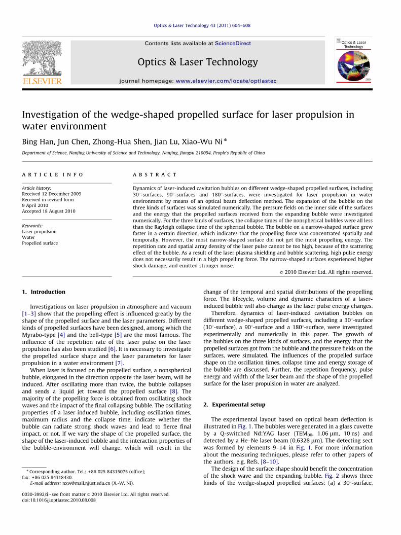
The experimental layout based on optical beam deflection isillustrated in Fig. 1. The bubbles were generated in a glass cuvetteby a Q-switched Nd:YAG laser (TEM00, 1.06 mm, 10 ns) anddetected by a He–Ne laser beam (0.6328 mm). The detecting sectwas formed by elements 9–14 in Fig. 1. For more informationabout the measuring techniques, please refer to other papers ofthe authors, e.g. Refs. [8–10].
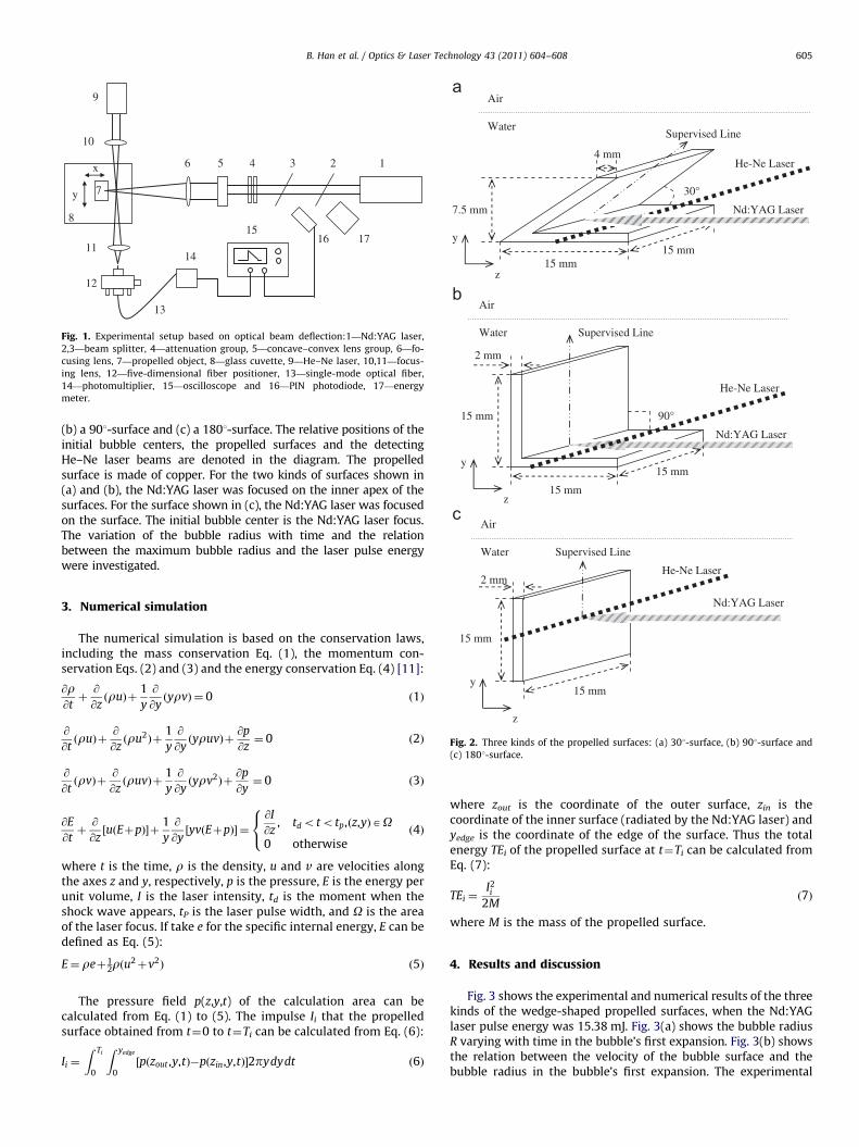
The design of the surface shape should benefit the concentrationof the shock wave and the expanding bubble. Fig. 2 shows threekinds of the wedge-shaped propelled surfaces: (a) a 301-surface,
9
10
8
7
11
12
14
1516
13
17
x
y
6 5 4 3 2 1
Fig. 1. Experimental setup based on optical beam deflection:1—Nd:YAG laser,
2,3—beam splitter, 4—attenuation group, 5—concave–convex lens group, 6—fo-
cusing lens, 7—propelled object, 8—glass cuvette, 9—He–Ne laser, 10,11—focus-
ing lens, 12—five-dimensional fiber positioner, 13—single-mode optical fiber,
14—photomultiplier, 15—oscilloscope and 16—PIN photodiode, 17—energy
meter.
30°
Nd:YAG Laser
Water
Air
He-Ne Laser
15 mm 15 mm
7.5 mm
4 mm
z
y
Supervised Line
2 mm
Nd:YAG Laser
90°
Water
Air
He-Ne Laser
15 mm
15 mm
15 mm
z
y
Supervised Line
Water
Air
He-Ne Laser
Supervised Line
B. Han et al. / Optics & Laser Technology 43 (2011) 604–608 605
(b) a 901-surface and (c) a 1801-surface. The relative positions of theinitial bubble centers, the propelled surfaces and the detectingHe–Ne laser beams are denoted in the diagram. The propelledsurface is made of copper. For the two kinds of surfaces shown in(a) and (b), the Nd:YAG laser was focused on the inner apex of thesurfaces. For the surface shown in (c), the Nd:YAG laser was focusedon the surface. The initial bubble center is the Nd:YAG laser focus.The variation of the bubble radius with time and the relationbetween the maximum bubble radius and the laser pulse energywere investigated.
Nd:YAG Laser
15 mm
2 mm
15 mm
z
y
Fig. 2. Three kinds of the propelled surfaces: (a) 301-surface, (b) 901-surface and
(c) 1801-surface.
3. Numerical simulation
The numerical simulation is based on the conservation laws,including the mass conservation Eq. (1), the momentum con-servation Eqs. (2) and (3) and the energy conservation Eq. (4) [11]:
@r@tþ@
@zðruÞþ
1
y
@
@yðyrvÞ ¼ 0 ð1Þ
@
@tðruÞþ
@
@zðru2Þþ
1
y
@
@yðyruvÞþ
@p
@z¼ 0 ð2Þ
@
@tðrvÞþ
@
@zðruvÞþ
1
y
@
@yðyrv2Þþ
@p
@y¼ 0 ð3Þ
@E
@tþ@
@zuðEþpÞ½ �þ
1
y
@
@yyvðEþpÞ½ � ¼
@I
@z, tdototp,ðz,yÞAO
0 otherwise
8<: ð4Þ
where t is the time, r is the density, u and v are velocities alongthe axes z and y, respectively, p is the pressure, E is the energy perunit volume, I is the laser intensity, td is the moment when theshock wave appears, tP is the laser pulse width, and O is the areaof the laser focus. If take e for the specific internal energy, E can bedefined as Eq. (5):
E¼ reþ12rðu
2þv2Þ ð5Þ
The pressure field p(z,y,t) of the calculation area can becalculated from Eq. (1) to (5). The impulse Ii that the propelledsurface obtained from t¼0 to t¼Ti can be calculated from Eq. (6):
Ii ¼
Z Ti
0
Z yedge
0½pðzout ,y,tÞ�pðzin,y,tÞ�2pydydt ð6Þ
where zout is the coordinate of the outer surface, zin is thecoordinate of the inner surface (radiated by the Nd:YAG laser) andyedge is the coordinate of the edge of the surface. Thus the totalenergy TEi of the propelled surface at t¼Ti can be calculated fromEq. (7):
TEi ¼I2i
2Mð7Þ
where M is the mass of the propelled surface.
4. Results and discussion
Fig. 3 shows the experimental and numerical results of the threekinds of the wedge-shaped propelled surfaces, when the Nd:YAGlaser pulse energy was 15.38 mJ. Fig. 3(a) shows the bubble radiusR varying with time in the bubble’s first expansion. Fig. 3(b) showsthe relation between the velocity of the bubble surface and thebubble radius in the bubble’s first expansion. The experimental

0
0.00.20.40.60.81.01.21.41.61.82.02.2
R (
mm
)
Experiment 30°Simulation 30°Experiment 90°Simulation 90°Experiment 180°Simulation 180°
Experiment 30°Simulation 30°Experiment 90°Simulation 90°Experiment 180°Simulation 180°
0.0
0
50
100
150
200
250
300
V (
m/s
)
R (mm)Time (µs)
10 20 30 40 50 60 70 80 90 100 0.5 1.0 1.5 2.0 2.5
Fig. 3. Experimental and numerical results of 301-surface, 901-surface and 1801-surface, when the Nd:YAG laser pulse energy was 15.38 mJ: (a) Bubble radius R varying
with time in the bubble’s first expansion. (b) Relation between the velocity of the bubble surface and the bubble radius in the bubble’s first expansion.
0
0
30
60
90
120
150
180
210
240
270
simulation 180°
simulation 30°
Tot
al E
nerg
y (µ
J)
simulation 90°
10 20 30 40 50 60 70
Time (µs)
Fig. 4. Numerical results of the energy that the three kinds of the propelled
surfaces got from the first expansion of the bubble, when the Nd:YAG laser pulse
energy was 15.38 mJ.
B. Han et al. / Optics & Laser Technology 43 (2011) 604–608606
results are five times averaged. Fig. 4 shows the numerical resultsof the energy that the three kinds of the propelled surfaces gotfrom the first expansion of the bubble, when the Nd:YAG laserpulse energy was 15.38 mJ. Table 1 shows the experimental resultsof the bubble oscillation times, the maximum bubble radius of thefirst oscillation Rmax1 (mm), the collapse time of the first oscillationT1 (ms), and the maximum radius Rmax (mm) that a bubble canreach when the pulse energy increases. The collapse time of thefirst oscillation calculated from Eq. (8) (Tc (ms)), and the bubbleenergy EB (mJ) of the maximum radius Rmax calculated from Eq. (9)are also shown in Table 1. It is noted that there are 2 values unableto be detected, ‘‘� ’’ in Table 1. Because when the pulse energy washigh, the laser-induced shock waves spread along the apex of the301-surfaces, which led to serious unsteady of the detecting beam.Except for the last two columns, the laser pulse energy was15.38 mJ. Fig. 5(a)–(c) shows the numerical results of the pressuredistribution on the supervised lines of the three kinds of thepropelled surfaces on different moments. The pressure field wasinduced by the shock wave emitted by the bubble during its firstexpansion. Fig. 5(d) shows the numerical results of the pressure ofthe shock wave front varying with time on the supervised lines ofthe three kinds of the propelled surfaces. The supervised lines onthe three kinds of the surfaces are shown in Fig. 2.
4.1. Collapse time of the laser-induced bubble
On the assumption that the flow field is infinite with aconstant pressure, and the condensability and viscosity areneglected, the collapse time Tc of a spherical bubble can bederived from the Rayleigh model based on the law of conservationof energy [12], and described as Eq. (8). The assumption above canbe called a Rayleigh-hypothesis:
TC ¼ 0:915Rmax
ffiffiffiffiffiffiffiffiffiffiffiffiffiffiffir
P1�Pv
rð8Þ
where Tc is the collapse time, Rmax is the maximum bubble radius,r is the flow density, PN is the environmental pressure and Pv isthe saturated vapor pressure. In this paper, the experiment wasimplemented at 20 1C, standard atmospheric pressure and thebubbles were generated about 50 mm beneath the water surface,so r is fixed to 1�103 kg/m3, PN is fixed to 1.01�105 Pa and Pv isfixed to 2.33�103 Pa. The calculated results of Tc for differentpropelled surfaces are given in Table 1.
In this paper, the quasi-duodecimal, quasi-quarter and quasi-half spherical cavitation bubbles were induced on 301-surface,901-surface and 1801-surface, respectively. Because of the Ray-leigh-hypothesis, Eq. (8) cannot describe these nonsphericalbubbles. So we detected the collapse time T1 of the first oscillationfor the different propelled surfaces experimentally. The experi-mental results are shown in Table 1.
The experimental results show that the collapse times of thequasi-duodecimal, the quasi-quarter and the quasi-half sphericalbubble were all less than the Rayleigh collapse time of thespherical bubble. Rmax1 of the quasi-duodecimal and the quasi-quarter spherical bubbles were bigger than that of the quasi-halfspherical bubble. The reason is that 301-surface and 901-surfacecompelled the bubble to grow in a certain direction. In addition, abubble induced by the former laser beam will scatter the laterlaser beam. This will stop the later laser energy from reaching theinitial focus on the propelled surface. Therefore, the collapse timeand the maximum radius are important for the design of thetemporal and spatial repetition frequency of the laser pulse.
4.2. Energy of the laser-induced bubble
With a fixed pulse width, if the pulse energy is increased toomuch, the laser plasma will be induced in the laser beam path andblocks the laser energy from reaching the initial focus, namely thelaser plasma shielding. This phenomenon will make the maximumbubble radius no longer increase with the laser pulse energy. In this

Table 1Experimental results of 301-surface, 901-surface and 1801-surface.
Experimental group Propelled surface (deg) Oscillation times Rmax1 (mm) T1 (ms) Tc (ms) Rmax (mm) EB (mJ)
1 30 1 2.18 177 200.81 – –
2 90 3 2.00 151 184.23 3.40 4.06
3 180 3 1.15 81 105.93 3.05 5.86
0
0
20
40
60
80
100
120
140
160
180
Pres
sure
(M
Pa)
Supervised Line (mm)
0.2 0.3 0.4 0.6 0.8 1.0 1.2 1.5 1.8 2.2 2.8 3.2 3.6 4.0 4.4 5.0
0.2
0.3
0.4
0.6
0.81.0
1.21.51.8 2.2 2.8 3.2 3.6 4.0 4.4 5.0
recorded time (µs)
0153045607590
105120135150165180
Pres
sure
(M
Pa)
0.2 0.4 0.5 0.6 0.8 1.0 1.3 1.6 1.9 2.3 2.7 3.3 4.0 4.6 5.3
0.2
0.40.5
0.60.8
1.01.31.61.9 2.3 2.7 3.3 4.0 4.6 5.3
recorded time (µs)
0153045607590
105120135150165180
2.01.4
1.0
Pres
sure
(M
Pa)
0.2
0.2 0.4 0.6 0.8 1.0 1.2 1.4 1.6 2.0 2.4 2.7 3.1 3.5 4.1 4.8 5.2
0.4
0.8 1.21.6
0.6
recorded time (µs)
2.42.7
3.1 3.5 4.1 4.8 5.2
0.00
20
40
60
80
100
120
140
160
180
Pres
sure
(M
Pa)
Simulation 30°Simulation 90°Simulation 180°
1 2 3 4 5 6 7
0
Supervised Line (mm)
1 2 3 4 5 6 7
0Supervised Line (mm)
1 2 3 4 5 6 7
Time (µs)
0.5 1.0 1.5 2.0 2.5 3.0 3.5 4.0 4.5 5.0 5.5
Fig. 5. (a)–(c) The numerical results of the pressure distribution on the supervised lines (shown in Fig. 2) of the three kinds of the propelled surfaces on different moments.
The pressure field was induced by the shock wave emitted by the bubble during its first expansion. (d) The numerical results of the pressure of the shock wave front varying
with time on the supervised lines of the three kinds of the propelled surfaces.
B. Han et al. / Optics & Laser Technology 43 (2011) 604–608 607
paper, the maximum radius Rmax that a bubble can reach when thepulse energy increases was detected. The experimental results fordifferent propelled surfaces are shown in Table 1.
Every time reaches the minimum volume, the bubble expandsrapidly and radiates a shock wave. The shock wave moves in theopposite direction to the propelled object, thus the object obtainsthe propelling force transformed from the bubble energy. For theenergy of the bubble decreases quickly, the energy of thesuccessive shock waves attenuate greatly. In the final collapse,the bubble transforms all its energy into the kinetic energy ofthe liquid jet, which impacts onto the propelled surface, and theobject is propelled for the last time. The bubble energy can bedescribed as Eq. (9) [12]:
EB ¼4p3ðP1�PvÞR
3max ð9Þ
It is noted that the maximum bubble radius Rmax shows theenergy of a bubble. Therefore, the propelling ability of a bubblecan be represented by Rmax. The energy of the quasi-half, quasi-quarter and quasi-duodecimal spherical cavitation bubbles can beroughly described as1/2EB, 1/4EB and1/12EB. The calculatedresults are shown in Table 1.
Fig. 4 shows that the energy that the 1801-surface got from thefirst expansion of the bubble is the highest, while the 301-surfacegot the smallest. Table 1 shows that the EB of the bubble on 1801-surface is higher than that on 901-surface. The experimental andnumerical results show that the maximum radius of the bubbleinduced on the 901-surface was increased because of thedirectional release of the bubble energy, but the total energy ofthe bubble EB was not concentrated effectively. It is reasonable toblame the energy loss (for 301-surface and 901-surface) on boththe laser plasma shielding and the bubble scattering. On the one

B. Han et al. / Optics & Laser Technology 43 (2011) 604–608608
hand, the plasma density was increased by the angle-shapedsurface, which increased the plasma shielding effect. On the otherhand, the expanding velocity of the bubble was increased by thedirectional release of the bubble energy, which made the bubblescattering effect appear earlier.
4.3. Shape of the propelled surface
It is noted that the bubble induced on the 301-surfaceoscillated only once, and the maximum radius and expandingvelocity of the bubble were both the highest. It indicates that thepropelling force can be concentrated temporally and spatially bythe narrow-shaped surface. However, because of the energy lossdiscussed in part 4.2, the 301-shaped surface did not get the mostpropelling energy. It is reasonable to speculate that the similarenergy loss phenomenon will happen for other shapes of thepropelled surfaces when the pulse energy increases. That is to say,high intensity or width of the laser pulse does not necessarilymean high propelling force.
Fig. 5 shows that the shock wave pressure on the 301-surface isthe highest, which enhances the propelling force, and in the sametime brings higher shock damage on the surface. The noise of thepropulsion comes from the attenuated shock wave. Thus the noisefrom the 301-surface was the highest.
5. Summary
The collapse time of the nonspherical bubbles were all lessthan the Rayleigh collapse time of the spherical bubble. Themaximum bubble radius was increased by the angle-shapedsurfaces. The collapse time and the maximum bubble radiusinfluence the design of the repeating frequency of the laser pulsetemporally and spatially. The bubble on a narrow-shaped surfacegrew in a certain direction at a higher velocity, which indicatesthat the propelling force was concentrated spatially and tempo-rally. However, because of the energy loss induced by the laserplasma shielding and the bubble scattering, the energy that thenarrowest-shaped surface got from the bubble was the lowest.Further, high pulse energy (high intensity or width) does not
necessarily mean high propelling force for all shapes of thepropelled surfaces, because of the energy loss phenomenon. Inaddition, narrow-shaped surface experiences higher shock da-mage, and emits stronger noise. This paper is to prepare fordiscussions about propulsion of axisymmetric confined surfacesby proposing the confined shape and opposing too narrow ones.
Acknowledgements
This project is supported by the NUST Research Funding underGrant No. 2010ZDJH09.
References
[1] Myrabo LN. The Apollo Lightcraft Project. NASA/USRA Advanced DesignProgram. In: Proceedings of the fifth annual summer conference, MarshallSpace Flight Center, Huntsville, Alabama, June 12–16, 1989.
[2] Ogata Y, Yabe T, Ookubo T. Numerical and experimental investigation of laserpropulsion. Appl Phys A 2004;79:829–31.
[3] Yabe T, Phipps C, Yamaguchi M. Microairplane propelled by laser drivenexotic target. Appl Phys Lett 2002; 80: 43l8-4320.
[4] Myrabo LN. World record flights of beam-riding rocket lightcraft: demonstra-tion of ‘‘disruptive’’ propulsion technology. In: Proceedings of the 37th AIAA/ASME/SAE/ASEE Joint Propulsion Conference, AIAA 2001-3798.
[5] Bohn WL, Schall WO. Laser propulsion activities in Germany. In: Pakhomov AV,editor. Beamed energy propulsion: first international symposium on beamedenergy propulsion, CP664. American Institute of Physics; 2003. p. 79–91.
[6] Tan RQ, Zheng YJ, Ke CJ, Wang DL, Zhang KH, Zheng G, et al. Experimentalstudy on laser propulsion of airbreathing mode. In: Komurasaki K, Yabe T,Uchida S, Sasoh A, editors. Beamed energy propulsion: fourth internationalsymposium, CP830, American Institute of Physics; 2006. p. 114–20.
[7] Han B, Shen ZH, Lu J, Ni XW. Laser propulsion for transport in waterenvironment. Mod Phys Lett B 2010;24(7):641–8.
[8] Chen X, Xu RQ, Shen ZH, Lu J, Ni XW. Optical investigation of cavitation erosionby laser-induced bubble collapse. Opt Laser Technol 2004;36:197–203.
[9] Han B, Chen J, Zhang HC, Shen ZH, Lu J, Ni XW. Influence of differentinterfaces on laser propulsion in water environment. Opt Laser Technol2010;42:1049–53.
[10] Zhao R, Xu RQ, Shen ZH, Lu J, Ni XW. Experimental investigation of thecollapse of laser-generated cavitation bubbles near a solid boundary. OptLaser Technol 2007;39:968–72.
[11] Yang YN, Zhao N, Ni XW. Reflection effects of spherical shock wave. Mod PhysLett B 2005;19:1451–4.
[12] Rayleigh L. On the pressure developed in liquid during the collapse of aspherical cavity. Philos Mag 1917;34:94–8.