investigation of transformer-based solutions for the...
TRANSCRIPT

0885-8993 (c) 2015 IEEE. Personal use is permitted, but republication/redistribution requires IEEE permission. Seehttp://www.ieee.org/publications_standards/publications/rights/index.html for more information.
This article has been accepted for publication in a future issue of this journal, but has not been fully edited. Content may change prior to final publication. Citation information: DOI10.1109/TPEL.2015.2459032, IEEE Transactions on Power Electronics
Abstract—A comprehensive literature review shows that
transformer based solutions are superior for the mitigation of
inrush currents than external (to the transformer) solutions. The
use of air gaps and low-permeability (iron) materials are known
techniques for this propose. This paper investigates the
effectiveness of these approaches for reducing inrush and phase-
hop currents. Studies are carried out on toroidal transformers,
due to their broad application in power electronics devices.
Contrary to common belief, this paper demonstrates that air gaps
do not reduce the inrush currents when a transformer is fully
demagnetized. However, inrush currents can be mitigated by the
use of low-permeability iron materials. It is also demonstrated that
air-gaps significantly reduce inrush currents when transformers
have residual flux, e.g. for phase-hop conditions. Analytical
expressions are derived to compute the mitigation factor for a
specific gap length. The results and formulae presented in this
paper are verified with laboratory experiments, transient
simulations with validated circuit models, and 2D finite element
simulations.
Index Terms-- Air-gap, inrush currents, low-permeability
materials, phase-hop current, toroidal transformers, UPS.
I. INTRODUCTION
Inrush currents are usually observed when a transformer
core is driven into very deep saturation at the time of
energization. The magnitude of inrush currents could be 10 to
30 times larger than the rated current depending on the
following parameters: switching angle, magnitude and polarity
of the voltage, residual flux in the core, saturation inductance
of the energized winding, winding resistance, impedance of the
source, geometry of the transformer core, and the core material
[1], [2].
Transformers can draw more destructive currents compared
to inrush currents when the cores have residual flux, or when a
phenomenon called “phase-hop” occurs [3]. The magnitude of
phase-hop currents might be twice as large as the zero-crossing
inrush currents. Phase-hop is not a commonly used term in the
literature. However, it needs to be known by power engineers,
since a wide range of power electronic devices may create
operating conditions which lead a transformer to draw phase-
hop currents. Possible reasons for the occurrence phase-hop
current are the switching of Uninterruptible Power Supply
(UPS) systems, voltage interruptions, voltage sags, and
notching [3].
Phase-hop and inrush currents are undesirable transient
phenomena in power systems. These abnormal events may
_____________________ R. Doğan, S. Jazebi, and F. de León are with the Department of Electrical
and Computer Engineering, New York University, Five Metrotech Center,
Brooklyn, NY, 11201 (e-mails: [email protected], [email protected], [email protected]).
result in significant voltage drops, which might cause false
tripping of protections or produce mechanical stresses on power
system components [4]. Thus, power quality, reliability, and
stability of the system can be affected.
Several solutions (external to the transformer) have been
proposed in the past to mitigate inrush currents; these include:
pre-insertion resistors [1], NTC (Negative Temperature
Coefficient) thermistors [5], controlled switching [6]-[9],
transformer core demagnetization [10], sequential phase
energization [11], [12], voltage sag compensators [13], [14],
and the application of series dc reactors [15]-[18].
Pre-insertion resistors, controlled switching, and core
demagnetization need additional control units and detection
circuits. Therefore, these circuits reduce the reliability of the
system, and increase the complexity and the final cost.
Furthermore, they are not applicable for mitigating the phase-
hop currents, because of the unpredictability of their occurrence
and the lack of time to react even if detected.
Transformer-based solutions, such as reduced flux density
designs, air-gaps, use of low permeability (unannealed) iron
core, and virtual air-gaps are more robust and effective
alternatives [3]. The infallible solution is to design transformers
at sufficiently low flux densities so that they never saturate.
However, transformers become larger, more expensive, and in
some applications there may not be sufficient space to
accommodate bulkier transformers. The virtual air-gap
technique uses external dc windings on the core [19]. The iron
core goes into a local saturation when the dc current is injected.
Computer simulation studies in [20] show that the dc excitation
creates the same effect as air-gap in the iron core.
It is believed that the use of unannealed cores gives similar
performance to the air-gaps with additional advantages [21]. In
this paper, the effect of air-gaps and low-permeability iron
materials is investigated and the advantages and disadvantages
are discussed. Numerous laboratory experiments accompanied
with computer simulations indicate that air-gaps are not always
capable to mitigate inrush currents especially when a
transformer is fully demagnetized.
For the first time, solutions to mitigate the phase-hop
currents are presented. It is shown via laboratory measurements
that for the inrush cases with initial residual flux and phase-hop,
the current amplitude reduces appreciably even with small air-
gaps. It is also demonstrated that special designs with low-
permeability iron materials could significantly reduce inrush
and phase-hop currents. The principal advantage of these
methods is their simplicity. These methods do not require any
control unit or monitoring device to detect the phase-hop.
Hence, they have perennial functionality.
The phase-hop current is produced by two consecutive semi-
Rasim Doğan, Saeed Jazebi, Member, IEEE, and Francisco de León, Fellow, IEEE
Investigation of Transformer-Based Solutions for
the Reduction of Inrush and Phase-Hop Currents
0885-8993 (c) 2015 IEEE. Personal use is permitted, but republication/redistribution requires IEEE permission. Seehttp://www.ieee.org/publications_standards/publications/rights/index.html for more information.
This article has been accepted for publication in a future issue of this journal, but has not been fully edited. Content may change prior to final publication. Citation information: DOI10.1109/TPEL.2015.2459032, IEEE Transactions on Power Electronics
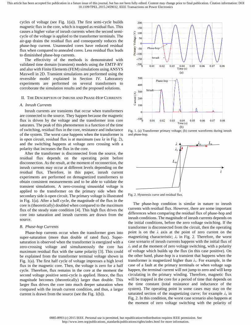
cycles of voltage (see Fig. 1(a)). The first semi-cycle builds
magnetic flux in the core, which is trapped as residual flux. This
causes a higher value of inrush currents when the second semi-
cycle of the voltage is applied to the transformer terminals. The
air-gap drains the residual flux and consequently reduces the
phase-hop current. Unannealed cores have reduced residual
flux when compared to annealed cores. Less residual flux leads
to diminished phase-hop currents.
The effectivity of the methods is demonstrated with
validated time domain (transient) models using the EMTP-RV
and also with Finite Elements (FEM) simulations using ANSYS
Maxwell in 2D. Transient simulations are performed using the
reversible model explained in Section IV. Laboratory
experiments are performed on several transformers to
corroborate the simulation results and the proposed solutions.
II. THE DESCRIPTION OF INRUSH AND PHASE-HOP CURRENTS
A. Inrush Currents
Inrush currents are transients that occur when transformers
are connected to the source. They happen because the magnetic
flux is driven by the voltage and the transformer iron core
saturates. The peak of this phenomenon is a function of the time
of switching, residual flux in the core, resistance and inductance
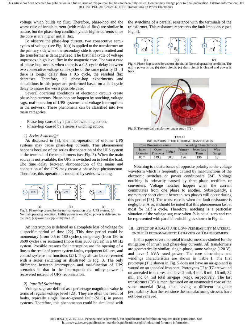
of the system. The worst case happens when the transformer is
in open circuit, residual flux is at maximum (see λr in Fig. 2),
and the switching happens at voltage zero crossing with a
polarity that increases the flux in the core.
After the transformer is disconnected from the source, the
residual flux depends on the operating point before
disconnection. As the result, at the moment of reconnection, the
inrush currents may occur at different levels depending on the
residual flux. Therefore, in this paper, inrush current
experiments are performed on demagnetized transformers to
obtain consistent measurements and to be able to validate the
transient simulations. A zero-crossing sinusoidal voltage is
applied to the transformer on the primary side when the
secondary side is open circuit. The primary voltage is illustrated
in Fig. 1(a). After a half cycle, the magnitude of the flux in the
core is (theoretically) doubled when compared to the maximum
flux of the steady state condition [4]. This high flux drives the
core into saturation and inrush currents are drawn from the
source.
B. Phase-hop Currents
Phase-hop currents occur when the transformer goes into
super-saturation (more than double of rated flux). Super-
saturation is observed when the transformer is energized with a
zero-crossing voltage and simultaneously the core has
maximum residual flux with the same polarity [3]. This could
be explained from the transformer terminal voltage shown in
Fig. 1(a). The first half cycle of voltage impresses a high level
flux in the magnetic core. Then, the voltage is zero for a half
cycle. Therefore, flux remains in the core at the moment the
second voltage positive semi-cycle is applied. Hence, the flux
magnitude becomes (theoretically) larger than double. This
larger flux drives the core into much deeper saturation when
compared with the inrush current condition, and thus, a larger
current is drawn from the source (see the Fig. 1(b)).
(a)
(b)
Fig. 1. (a) Transformer primary voltage; (b) current waveforms during inrush and phase-hop.
λr
Ls
Lm
i
λ λs
Fig. 2. Hysteresis curve and residual flux.
The phase-hop condition is similar in nature to inrush
currents with residual flux. However, there are some important
differences when comparing the residual flux of phase-hop and
inrush conditions. The magnitude of inrush currents depends on
the initial conditions, before the zero voltage switching. If the
transformer is disconnected from the circuit, then the operating
point is on the λ axis at the point of zero current on the
magnetizing characteristic; λr in Fig. 2. Therefore, the worst
case scenario of inrush currents happens with the initial flux of
λr and at the moment of zero voltage switching, with a polarity
of voltage which builds up the flux (in this case positive). On
the other hand, phase-hop is a transient that happens when the
transformer is magnetized higher than λr. For example, in the
case of a fault at the primary terminals or when voltage sags
happen, the terminal current will not jump to zero and will keep
circulating in the primary winding. Therefore, magnetic flux
will be trapped in the core for a period of time that depends on
the time constant (total resistance and inductance of the
system). The operating point in some cases may stay on the
saturated section of the magnetizing curve; for example λs in
Fig. 2. In this condition, the worst case scenario also happens at
the moment of zero voltage switching with the polarity of
0885-8993 (c) 2015 IEEE. Personal use is permitted, but republication/redistribution requires IEEE permission. Seehttp://www.ieee.org/publications_standards/publications/rights/index.html for more information.
This article has been accepted for publication in a future issue of this journal, but has not been fully edited. Content may change prior to final publication. Citation information: DOI10.1109/TPEL.2015.2459032, IEEE Transactions on Power Electronics
voltage which builds up flux. Therefore, phase-hop and the
worst case of inrush current (with residual flux) are similar in
nature, but the phase-hop condition yields higher currents since
the core is at a higher initial flux.
To observe the phase-hop current, two consecutive semi-
cycles of voltage (see Fig. 1(a)) is applied to the transformer on
the primary side when the secondary side is open circuited and
the transformer is demagnetized. The first half cycle of voltage
impresses a high level flux in the magnetic core. The worst case
of phase-hop occurs when there is a 0.5 cycle delay between
two consecutive voltage semi-cycles of the same polarity [3]. If
there is longer delay than a 0.5 cycle, the residual flux
decreases. Therefore, all phase-hop experiments and
simulations in this paper are performed based on a half cycle
delay to assure the worst possible case.
Several operating conditions of electronic circuits create
phase-hop currents. Phase-hop can happen by notching, voltage
sags, mal-operation of UPS systems, and voltage interruptions
in the network. These phenomena can be classified into two
main categories:
- Phase-hop caused by a parallel switching action.
- Phase-hop caused by a series switching action.
1) Series Switching:
As discussed in [3], the mal-operation of off-line UPS
systems may cause phase-hop currents. This phenomenon
happens because of the series disconnection of the UPS system
at the terminal of the transformers (see Fig. 3). When the main
source is not available, the UPS is switched on to feed the load.
The time delay between disconnection of the mains and
connection of the UPS may create a phase-hop phenomenon.
Therefore, this operation is modeled by series switching.
UPSUPS UPS
(a) (b) (c)
Fig. 3. Phase-hop caused by the normal operation of an UPS system. (a)
Normal operating condition. Utility power is on; (b) no power is delivered to
the load; (c) power is supplied by the UPS.
An interruption is defined as a complete loss of voltage for
a specific period of time [22]. This time period could be
momentary (from 0.5 to 180 cycles), temporary (from 180 to
3600 cycles), or sustained (more than 3600 cycles) in a 60 Hz
system. Possible reasons for interruption are the opening of a
line as the result of power system faults, equipment failures, and
control systems malfunctions [23]. They all can be represented
with a series switching as illustrated in Fig. 3. The only
difference between interruption and mal-function of UPS
scenarios is that in the interruption the utility power is
recovered instead of UPS reconnection.
2) Parallel Switching:
Voltage sags are defined as a percentage magnitude value in
terms of regular voltage level [23]. They are often the result of
faults, typically single line-to-ground fault (SLG), in power
systems. Therefore, this phenomenon could be simulated with
the switching of a parallel resistance with the terminals of the
transformer. This resistance represents the fault impedance (see
Fig. 4).
RfRf Rf
(a) (b) (c)
Fig. 4. Phase-hop caused by a short circuit. (a) Normal operating condition. The utility power is on; (b) short circuit; (c) short circuit is cleared and power is
back.
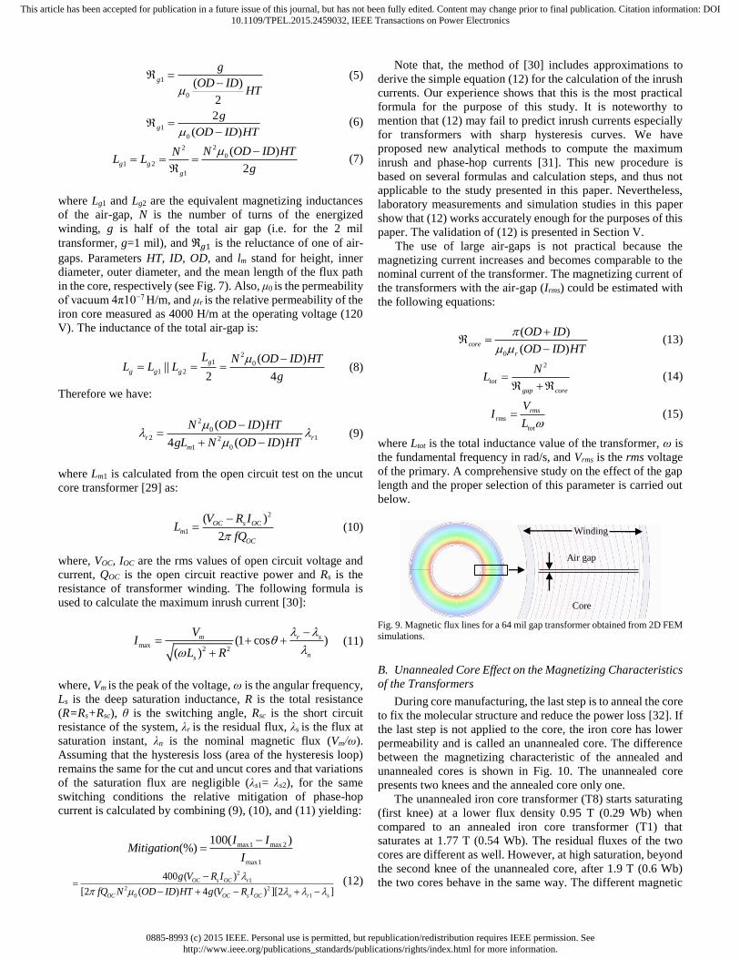
Fig. 5. The toroidal transformer under study (T1).
TABLE I
INFORMATION OF THE TOROIDAL TRANSFORMERS
Core Dimensions (mm) Winding Characteristics
Inner Diameter
Outer Diameter
Height Primary Turns
Secondary Turns
Wire Gauge
85.7 149.2 50.8 196 196 13
Notching is a disturbance of opposite polarity to the voltage
waveform which is frequently caused by mal-functions of the
electronic switches or power conditioners [24]. Voltage
notching is primarily caused by three-phase rectifiers or
converters. Voltage notches happen when the current
commutates from one phase to another. Subsequently, a
momentary short circuit between two phases will occur during
this period [23]. The worst case is when the fault resistance is
negligible. Also, it should be noted that this phenomenon last at
most for half a cycle. Therefore, notching is a particular
situation of the voltage sag case when Rf is equal zero and can
be represented with parallel switching as shown in Fig. 4.
III. EFFECT OF AIR-GAP AND LOW-PERMEABILITY MATERIAL
ON THE ELECTROMAGNETIC BEHAVIOR OF TRANSFORMERS
In this paper several toroidal transformers are studied for the
mitigation of inrush and phase-hop currents. All transformers
are geometrically similar, single-phase, same voltage (120 V),
and have 1 kVA rated power. The core dimensions and
windings characteristics are shown in Table I. The first
prototype (T1) shown in Fig. 5 does not have an air-gap and is
wound on an annealed iron core. Prototypes T2 to T7 are wound
on annealed iron cores and have 2 mil, 4 mil, 8 mil, 16 mil, 32
mil, and 64 mil total air-gaps (=2g), respectively. The last
transformer (T8) is manufactured on an unannealed core of the
same material (M4), thus having a different magnetic
permeability than the rest since the manufacturing stresses have
not been relieved.

0885-8993 (c) 2015 IEEE. Personal use is permitted, but republication/redistribution requires IEEE permission. Seehttp://www.ieee.org/publications_standards/publications/rights/index.html for more information.
This article has been accepted for publication in a future issue of this journal, but has not been fully edited. Content may change prior to final publication. Citation information: DOI10.1109/TPEL.2015.2459032, IEEE Transactions on Power Electronics
Toroidal transformers have very sharp hysteresis curves
when compared to standard transformers because they do not
have air-gaps in the core. The sharp hysteresis curve results in
large residual flux because the magnetizing curve crosses at a
higher value of flux when the current is zero. The use of air-
gaps and low-permeability materials change this characteristic
as demonstrated in the following subsections.
A. Air-gap Effect on the Magnetizing Characteristics of
Transformers
Open-circuit tests are performed on transformers with
different air-gap lengths according to the IEEE Std. C57.12.91-
1995 [25]. Hence, the open circuit tests are performed with 120
V applied to the primary terminal. The primary current and
secondary voltage are measured. The linkage flux is derived
from the integration of the secondary voltage [26]. As a result,
the hysteresis curves for uncut and all six gapped transformers
are shown in Fig. 6. The measured residual fluxes (flux
corresponding to zero terminal current) for each transformer are
presented in Table II (see Fig. 6 as well). Measurements
demonstrate dramatic changes in the magnetic behavior of the
transformers with different air-gaps lengths. One can observe
that the flux follows different magnetizing paths depending on
the length of the air-gap. Most importantly, the residual flux
reduces noticeably. Therefore, for a transformer with an air-
gap, when the terminal current tends to zero at the moment of
disconnection from the source, the flux also tends to zero, and
the core will be demagnetized.
Theoretically, a larger gap results in a lower slope (see Fig.
6). The reason can be explained from the reluctance circuit of
the toroidal transformer shown in Fig. 7 and a piecewise linear
approximation of the hysteresis curve (see Fig. 8).
According to the principle of duality between magnetic and
equivalent electrical circuits, the air-gap can be represented
with a parallel linear inductance with the non-linear
magnetizing branch as shown in Fig. 7 [27]. The parallel
connection of the linear inductance (Lg), changes the slope of
the magnetizing curve (L) that is shown in Fig. 8. According to
this figure, the following expressions can be written for λ=0:
0 = Lm1 (–Ic) + λr1 ⇒ Ic = λr1 / Lm1 (1)
0 = Lm2 (–Ic) + λr2 ⇒ Ic = λr2 / Lm2 (2)
where Ic is the coercive current [28]. Therefore we get:
2
2 1
1
m
r r
m
L
L (3)
The magnetizing inductance of the transformer with air-gap
(Lm2) is smaller than the magnetizing inductance of the uncut
transformer (Lm1). Therefore, the air-gap decreases the residual
flux from λr1 to λr2 according to (3). Note from Fig. 7 that, Lm2=
Lm1 || Lg, hence substituting Lm2 in (3) yields:
2 1
1
g
r r
m g
L
L L
(4)
Neglecting the fringing effects and assuming a uniform
magnetic field (see Fig. 9):
Fig. 6. Hysteresis characteristic of uncut and all gapped transformers obtained
by measurements.
OD
HTID
g
lm
+ -
+
-LLgmmf
mmf
g2
core
g1
core
g1
g2
Fig. 7. Dimensions and the magnetic equivalent circuit of the core with air-gap. Note that g is half of the total air-gap. To create air-gaps in the iron core,
transformer manufacturers diametrically cut the core into two halves. Then the
surfaces are grinded, burnished, and kept apart with Mylar or epoxy fiberglass laminates glued and banded to keep the separation distance well controlled.
Finally the transformer is wound as usual.
λr1
λr2
Ls
Lm1Lm2
-Ic I
λ
Fig. 8. Hysteresis characteristic (L) of transformer iron core represented by two constant slopes; the effect of the gap (Lg) on the hysteresis curve is shown.
TABLE II
MEASURED RESIDUAL FLUX FOR TRANSFORMERS
Transformer λresidual [mWb]
Uncut (T1) 541
2 mil (T2) 57
4 mil (T3) 51
8 mil (T4) 45
16 mil (T5) 28
32 mil (T6) 19
64 mil (T7) 17
0885-8993 (c) 2015 IEEE. Personal use is permitted, but republication/redistribution requires IEEE permission. Seehttp://www.ieee.org/publications_standards/publications/rights/index.html for more information.
This article has been accepted for publication in a future issue of this journal, but has not been fully edited. Content may change prior to final publication. Citation information: DOI10.1109/TPEL.2015.2459032, IEEE Transactions on Power Electronics
1
0
( )
2
g
g
OD IDHT
(5)
1
0
2
( )g
g
OD ID HT
(6)
22
0
1 2
1
( )
2g g
g
N OD ID HTNL L
g
(7)
where Lg1 and Lg2 are the equivalent magnetizing inductances
of the air-gap, N is the number of turns of the energized
winding, g is half of the total air gap (i.e. for the 2 mil
transformer, g=1 mil), and ℜ𝑔1 is the reluctance of one of air-
gaps. Parameters HT, ID, OD, and lm stand for height, inner
diameter, outer diameter, and the mean length of the flux path
in the core, respectively (see Fig. 7). Also, μ0 is the permeability
of vacuum 4π10−7 H/m, and μr is the relative permeability of the
iron core measured as 4000 H/m at the operating voltage (120
V). The inductance of the total air-gap is:
21 0
1 2
( )||
2 4
g
g g g
L N OD ID HTL L L
g
(8)
Therefore we have:
2
0
2 12
1 0
( )
4 ( )r r
m
N OD ID HT
gL N OD ID HT
(9)
where Lm1 is calculated from the open circuit test on the uncut
core transformer [29] as:
2
1
( )
2
OC s OC
m
OC
V R IL
fQ
(10)
where, VOC, IOC are the rms values of open circuit voltage and
current, QOC is the open circuit reactive power and Rs is the
resistance of transformer winding. The following formula is
used to calculate the maximum inrush current [30]:
max2 2
(1 cos )( )
m r s
ns
VI
L R
(11)
where, Vm is the peak of the voltage, ω is the angular frequency,
Ls is the deep saturation inductance, R is the total resistance
(R=Rs+Rsc), θ is the switching angle, Rsc is the short circuit
resistance of the system, λr is the residual flux, λs is the flux at
saturation instant, λn is the nominal magnetic flux (Vm/ω).
Assuming that the hysteresis loss (area of the hysteresis loop)
remains the same for the cut and uncut cores and that variations
of the saturation flux are negligible (λs1= λs2), for the same
switching conditions the relative mitigation of phase-hop
current is calculated by combining (9), (10), and (11) yielding:
max1 max 2
max1
100( )(%)
I IMitigation
I
2
1
2 2
0 1
400 ( )
[2 ( ) 4 ( ) ][2 ]
OC s OC r
OC OC s OC n r s
g V R I
fQ N OD ID HT g V R I
(12)
Note that, the method of [30] includes approximations to
derive the simple equation (12) for the calculation of the inrush
currents. Our experience shows that this is the most practical
formula for the purpose of this study. It is noteworthy to
mention that (12) may fail to predict inrush currents especially
for transformers with sharp hysteresis curves. We have
proposed new analytical methods to compute the maximum
inrush and phase-hop currents [31]. This new procedure is
based on several formulas and calculation steps, and thus not
applicable to the study presented in this paper. Nevertheless,
laboratory measurements and simulation studies in this paper
show that (12) works accurately enough for the purposes of this
paper. The validation of (12) is presented in Section V.
The use of large air-gaps is not practical because the
magnetizing current increases and becomes comparable to the
nominal current of the transformer. The magnetizing current of
the transformers with the air-gap (Irms) could be estimated with
the following equations:
0
( )
( )core
r
OD ID
OD ID HT
(13)
2
tot
gap core
NL
(14)
rms
rms
tot
VI
L (15)
where Ltot is the total inductance value of the transformer, ω is
the fundamental frequency in rad/s, and Vrms is the rms voltage
of the primary. A comprehensive study on the effect of the gap
length and the proper selection of this parameter is carried out
below.
Fig. 9. Magnetic flux lines for a 64 mil gap transformer obtained from 2D FEM
simulations.
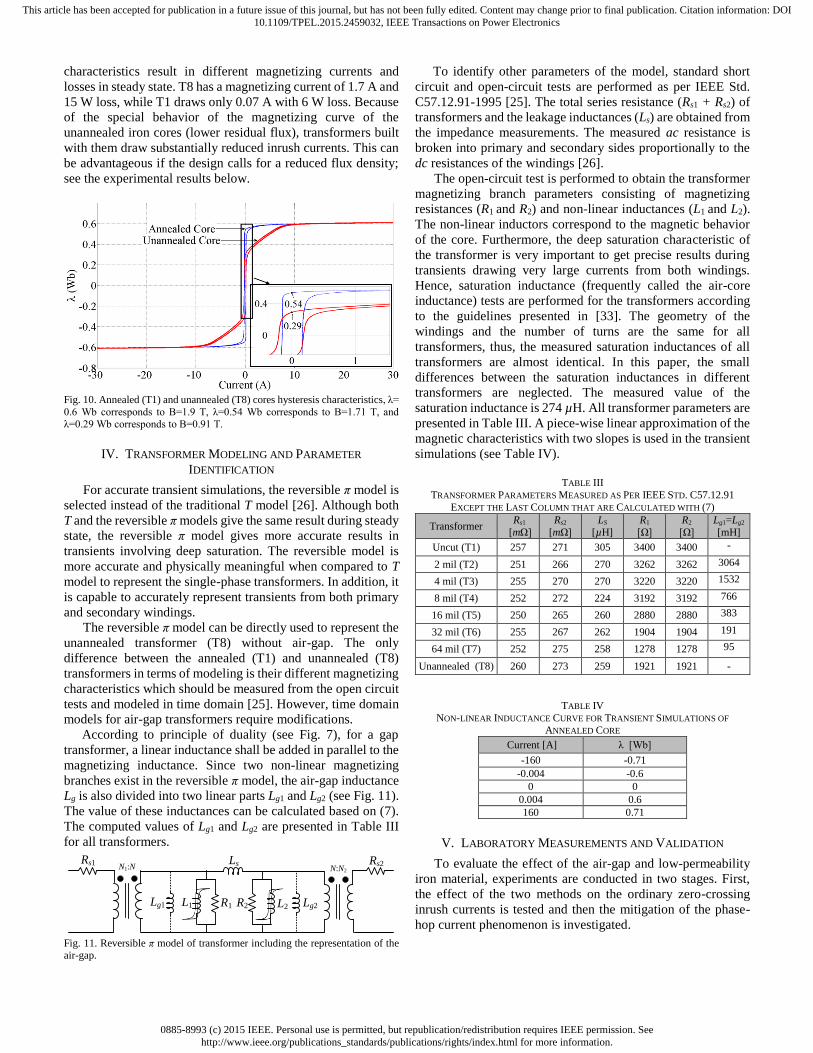
B. Unannealed Core Effect on the Magnetizing Characteristics
of the Transformers
During core manufacturing, the last step is to anneal the core
to fix the molecular structure and reduce the power loss [32]. If
the last step is not applied to the core, the iron core has lower
permeability and is called an unannealed core. The difference
between the magnetizing characteristic of the annealed and
unannealed cores is shown in Fig. 10. The unannealed core
presents two knees and the annealed core only one.
The unannealed iron core transformer (T8) starts saturating
(first knee) at a lower flux density 0.95 T (0.29 Wb) when
compared to an annealed iron core transformer (T1) that
saturates at 1.77 T (0.54 Wb). The residual fluxes of the two
cores are different as well. However, at high saturation, beyond
the second knee of the unannealed core, after 1.9 T (0.6 Wb)
the two cores behave in the same way. The different magnetic
Winding
Core
Air gap
0885-8993 (c) 2015 IEEE. Personal use is permitted, but republication/redistribution requires IEEE permission. Seehttp://www.ieee.org/publications_standards/publications/rights/index.html for more information.
This article has been accepted for publication in a future issue of this journal, but has not been fully edited. Content may change prior to final publication. Citation information: DOI10.1109/TPEL.2015.2459032, IEEE Transactions on Power Electronics
characteristics result in different magnetizing currents and
losses in steady state. T8 has a magnetizing current of 1.7 A and
15 W loss, while T1 draws only 0.07 A with 6 W loss. Because
of the special behavior of the magnetizing curve of the
unannealed iron cores (lower residual flux), transformers built
with them draw substantially reduced inrush currents. This can
be advantageous if the design calls for a reduced flux density;
see the experimental results below.
Fig. 10. Annealed (T1) and unannealed (T8) cores hysteresis characteristics, λ=
0.6 Wb corresponds to B=1.9 T, λ=0.54 Wb corresponds to B=1.71 T, and λ=0.29 Wb corresponds to B=0.91 T.
IV. TRANSFORMER MODELING AND PARAMETER
IDENTIFICATION
For accurate transient simulations, the reversible π model is
selected instead of the traditional T model [26]. Although both
T and the reversible π models give the same result during steady
state, the reversible π model gives more accurate results in
transients involving deep saturation. The reversible model is
more accurate and physically meaningful when compared to T
model to represent the single-phase transformers. In addition, it
is capable to accurately represent transients from both primary
and secondary windings.
The reversible π model can be directly used to represent the
unannealed transformer (T8) without air-gap. The only
difference between the annealed (T1) and unannealed (T8)
transformers in terms of modeling is their different magnetizing
characteristics which should be measured from the open circuit
tests and modeled in time domain [25]. However, time domain
models for air-gap transformers require modifications.
According to principle of duality (see Fig. 7), for a gap
transformer, a linear inductance shall be added in parallel to the
magnetizing inductance. Since two non-linear magnetizing
branches exist in the reversible π model, the air-gap inductance
Lg is also divided into two linear parts Lg1 and Lg2 (see Fig. 11).
The value of these inductances can be calculated based on (7).
The computed values of Lg1 and Lg2 are presented in Table III
for all transformers.
Rs1 Ls
L1 L2R1 R2
Rs2N1:N N:N2
Lg1 Lg2
Fig. 11. Reversible π model of transformer including the representation of the air-gap.
To identify other parameters of the model, standard short
circuit and open-circuit tests are performed as per IEEE Std.
C57.12.91-1995 [25]. The total series resistance (Rs1 + Rs2) of
transformers and the leakage inductances (Ls) are obtained from
the impedance measurements. The measured ac resistance is
broken into primary and secondary sides proportionally to the
dc resistances of the windings [26].
The open-circuit test is performed to obtain the transformer
magnetizing branch parameters consisting of magnetizing
resistances (R1 and R2) and non-linear inductances (L1 and L2).
The non-linear inductors correspond to the magnetic behavior
of the core. Furthermore, the deep saturation characteristic of
the transformer is very important to get precise results during
transients drawing very large currents from both windings.
Hence, saturation inductance (frequently called the air-core
inductance) tests are performed for the transformers according
to the guidelines presented in [33]. The geometry of the
windings and the number of turns are the same for all
transformers, thus, the measured saturation inductances of all
transformers are almost identical. In this paper, the small
differences between the saturation inductances in different
transformers are neglected. The measured value of the
saturation inductance is 274 µH. All transformer parameters are
presented in Table III. A piece-wise linear approximation of the
magnetic characteristics with two slopes is used in the transient
simulations (see Table IV).
TABLE III
TRANSFORMER PARAMETERS MEASURED AS PER IEEE STD. C57.12.91
EXCEPT THE LAST COLUMN THAT ARE CALCULATED WITH (7)
Transformer Rs1
[mΩ]
Rs2
[mΩ]
LS
[µH]
R1
[Ω]
R2
[Ω]
Lg1=Lg2
[mH]
Uncut (T1) 257 271 305 3400 3400 -
2 mil (T2) 251 266 270 3262 3262 3064
4 mil (T3) 255 270 270 3220 3220 1532
8 mil (T4) 252 272 224 3192 3192 766
16 mil (T5) 250 265 260 2880 2880 383
32 mil (T6) 255 267 262 1904 1904 191
64 mil (T7) 252 275 258 1278 1278 95
Unannealed (T8) 260 273 259 1921 1921 -
TABLE IV
NON-LINEAR INDUCTANCE CURVE FOR TRANSIENT SIMULATIONS OF
ANNEALED CORE
Current [A] λ [Wb]
-160 -0.71
-0.004 -0.6
0 0
0.004 0.6
160 0.71
V. LABORATORY MEASUREMENTS AND VALIDATION
To evaluate the effect of the air-gap and low-permeability
iron material, experiments are conducted in two stages. First,
the effect of the two methods on the ordinary zero-crossing
inrush currents is tested and then the mitigation of the phase-
hop current phenomenon is investigated.
0885-8993 (c) 2015 IEEE. Personal use is permitted, but republication/redistribution requires IEEE permission. Seehttp://www.ieee.org/publications_standards/publications/rights/index.html for more information.
This article has been accepted for publication in a future issue of this journal, but has not been fully edited. Content may change prior to final publication. Citation information: DOI10.1109/TPEL.2015.2459032, IEEE Transactions on Power Electronics
A. Inrush Current Experiments
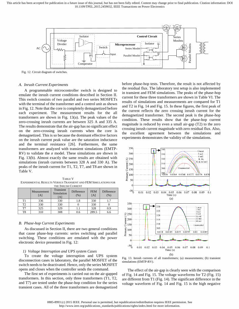
A programmable microcontroller switch is designed to
emulate the inrush current conditions described in Section II.
This switch consists of two parallel and two series MOSFETs
with the terminal of the transformer and a control unit as shown
in Fig. 12. Note that the core is completely demagnetized before
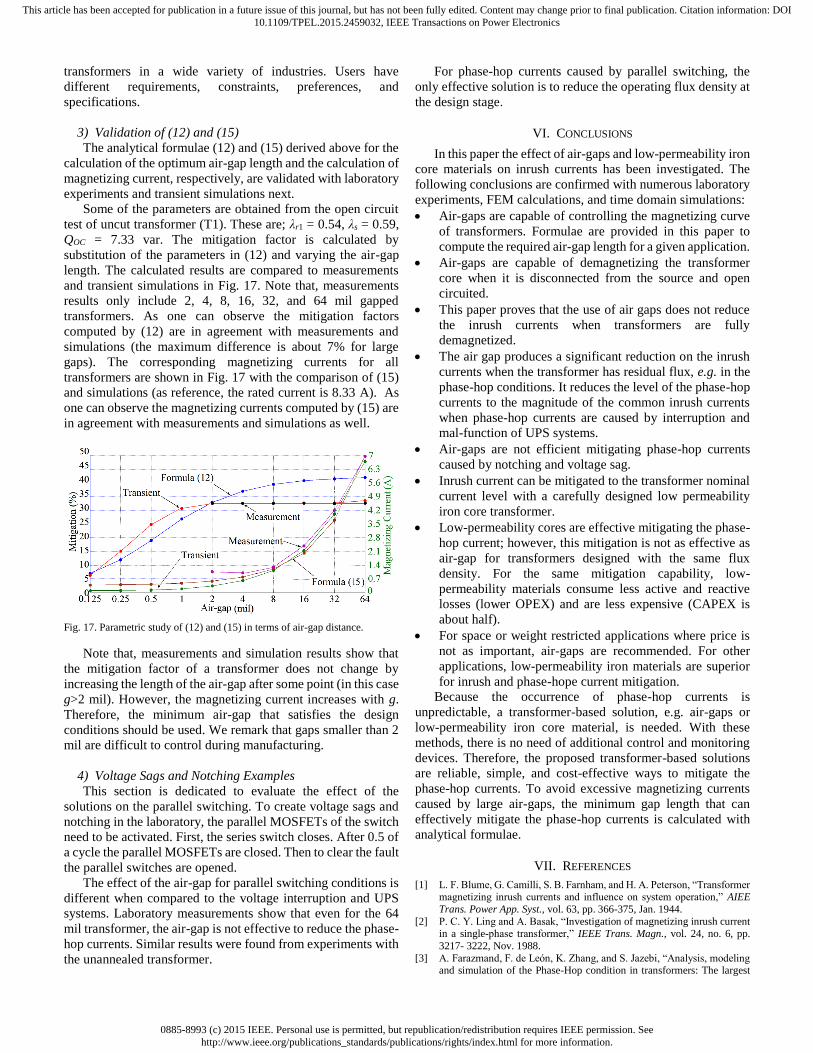
each experiment. The measurement results for the all
transformers are shown in Fig. 13(a). The peak values of the
zero-crossing inrush currents are between 325 A and 335 A.
The results demonstrate that the air-gap has no significant effect
on the zero-crossing inrush currents when the core is
demagnetized. This is so because the dominant effective factors
on the inrush current peak value are the saturation inductance
and the terminal resistance [26]. Furthermore, the same
transformers are analyzed with transient simulations (EMTP-
RV) to validate the π model. These simulations are shown in
Fig. 13(b). Almost exactly the same results are obtained with
simulations (inrush currents between 328 A and 330 A). The
peaks of the inrush current for T1, T2, T7, and T8 are shown in
Table V.
TABLE V EXPERIMENTAL RESULTS VERSUS TRANSIENT AND FEM SIMULATIONS FOR
THE INRUSH CURRENT
Measurement
[A]
Transient Simulation
[A]
Difference
(%)
FEM
[A]
Difference
(%)
T1 336 330 1.8 330 1.7
T2 330 330 0 330 0
T7 325 329 1.1 328 0.9
T8 310 308 0.6 289.5 6.6
B. Phase-hop Current Experiments
As discussed in Section II, there are two general conditions
that cause phase-hop currents: series switching and parallel
switching. These conditions are emulated with the power
electronic device presented in Fig. 12:
1) Voltage Interruption and UPS system Cases
To create the voltage interruption and UPS system
disconnection cases in laboratory, the parallel MOSFET of the
switch needs to be deactivated. Hence, only the series MOSFET
opens and closes when the controller sends the command.
The first set of experiments is carried out on the air-gapped
transformers. In this section, only three transformers (T1, T2,
and T7) are tested under the phase-hop condition for the series
transient cases. All of the three transformers are demagnetized
before phase-hop tests. Therefore, the result is not affected by
the residual flux. The laboratory test setup is also implemented
in transient and FEM simulations. The peaks of the phase-hop
current for these three transformers are shown in Table VI. The
results of simulations and measurements are compared for T1
and T2 in Fig. 14 and Fig. 15. In these figures, the first peak of
the current reflects the zero crossing inrush current for the
demagnetized transformer. The second peak is the phase-hop
condition. These results show that the phase-hop current
magnitude is reduced by even a small air-gap (T2) to the zero
crossing inrush current magnitude with zero residual flux. Also,
the excellent agreement between the simulations and
experiments demonstrates the validity of the simulations.
(a)
(b)
Fig. 13. Inrush currents of all transformers; (a) measurements; (b) transient simulations (EMTP-RV).
The effect of the air-gap is clearly seen with the comparison
of Fig. 14 and Fig. 15. The voltage waveforms for T2 (Fig. 15)
are different from T1 (Fig. 14). The significant difference in the
voltage waveform of Fig. 14 and Fig. 15 is the high negative
Microprocessor
Input
Comperator
Switch
Isolator
Isolator
Parallel Mosfet
Series Mosfet
5V
Voltage
Divider
Series
Mosfets
Par
alle
l M
osf
ets
Control Circuit
AC
5V
Fig. 12. Circuit diagram of switches.

0885-8993 (c) 2015 IEEE. Personal use is permitted, but republication/redistribution requires IEEE permission. Seehttp://www.ieee.org/publications_standards/publications/rights/index.html for more information.
This article has been accepted for publication in a future issue of this journal, but has not been fully edited. Content may change prior to final publication. Citation information: DOI10.1109/TPEL.2015.2459032, IEEE Transactions on Power Electronics
peak seen in Fig. 15. This means that the linkage flux is reduced
in the cut transformer when the switch is open. Therefore, the
air-gap transformer restores the energy to the source. As a
result, the residual flux decreases and the core is demagnetized.
This is demonstrated in Fig. 16 where the linkage flux of the
two transformers is compared with transient simulations.
TABLE VI
EXPERIMENTAL RESULTS VERSUS TRANSIENT AND FEM SIMULATIONS FOR
THE SERIES SWITCHING TRANSIENTS – PHASE-HOP CURRENT
Measurement
[A]
Transient
Simulation [A]
Difference
(%)
FEM
[A]
Difference
(%)
T1 490 484.0 1.22 480.0 2.0
T2 330 329.8 0.06 325.6 1.4
T7 330 330.0 0 328.2 0.5
Fig. 14. Comparison of simulations and experiments for the phase-hop
condition for T1 (non-gapped); voltage and current from experiments and
simulated current with FEM and transient simulations. The first peak of the current is the zero crossing inrush current and the second peak is the phase-hop
current.
Fig. 15. Comparison of model and experiment for the phase-hop condition for T2 (gapped); voltage and current from experiments and simulated with FEM
and transient simulations. The first peak of the current is the zero crossing
inrush current and the second peak is the phase-hop condition.
2) Design Considerations for Mitigation of the Phase-hop
Currents
The second set of experiments is carried out on the
annealed, 2 mil, and the unannealed core transformers that are
designed for different flux densities (1.5 T, 1.25 T, 1.12 T, 1 T,
0.87 T, and 0.75 T). The results are presented in Table VII. The
annealed core transformers draw a considerably higher phase-
hop currents than the 2 mil and unannealed core at the rated 1.5
T. This is so because the residual fluxes of these transformers
are smaller than in the annealed core ones (see Fig. 6 and Fig.
10). Overall, the phase-hop current of the annealed core
transformers is larger than that of the 2 mil and unannealed core
transformers.
Assuming that transformers are designed with the same flux
densities, the gapped transformer performs better to reduce the
phase-hop currents. The active power losses are the same for
the unannealed and the gap transformers. However, the gapped
transformer draws larger magnetizing current which is the
indication of a higher reactive power required by this
transformer. Assuming the same mitigation factor, the
transformer designed with unannealed core draws less reactive
and active power; however, it is larger and heavier because it
should be designed for lower flux density. For example to
reduce the phase-hop about 75%, the unannealed transformer
consumes almost 50% less reactive and 30% less active power,
but the transformer needs to be designed at about 10% lower
flux density when compared to the gapped transformer, which
increases the size and weight; see Table VII.
The results presented in Table VII indicate that gapped
transformers are more efficient reducing inrush and phase-hop
currents, but with higher Capital Cost (CAPEX) and Operation
Costs (OPEX). However, for a space or weight restricted
application, where the acquisition cost is a less important factor
than size and weight, gapped transformers are superior.
Fig. 16. Linkage flux of the two transformers obtained by transient simulations.
TABLE VII EXPERIMENTAL RESULTS OF ANNEALED, UNANNEALED, AND 2-MIL GAPPED
TRANSFORMERS. PHASE-HOP CURRENT, MAGNETIZING CURRENT, AND NO-
LOAD POWER FOR DIFFERENT FLUX DENSITIES
Flux Density
[T] 1.5 1.25 1.12 1 0.87 0.75
Inrush
[A]
Annealed 330 94 58 1.5 0.38 0.1
2-mil gap 330 105 47 3.2 1.3 1.2
Unannealed 310 100 55 6.7 4.8 2.7
Phase-hop
[A]
Annealed 490 255 210 175 125 50
2-mil gap 330 112 53 3.6 1.4 1.2
Unannealed 366 164 116 74 30 8
Imag
[mA]
Annealed 70 45 38 33 29 26
2-mil gap 900 770 740 680 610 570
Unannealed 1770 720 390 190 100 70
P0
[W]
Annealed 6 4 3 2 2 1
2-mil gap 15 7 5 4 3 2
Unannealed 15 7 5 4 3 2
It should be noted that both of the mechanical procedures to
anneal and create a gap (cut and reunite), increases the
acquisition cost. The cut core transformers purchased for this
study cost about twice than the uncut transformers. Generally,
the acquisition cost or the total ownership cost (TOC) of a
product dictates the technology that can be implemented for a
special problem. The selection of a solution shall be made with
a trade-off between the total cost, required operation
characteristics, and the mitigation capability. For this purpose,
transformer manufacturers need to understand the target
market. There are many different applications for toroidal
0885-8993 (c) 2015 IEEE. Personal use is permitted, but republication/redistribution requires IEEE permission. Seehttp://www.ieee.org/publications_standards/publications/rights/index.html for more information.
This article has been accepted for publication in a future issue of this journal, but has not been fully edited. Content may change prior to final publication. Citation information: DOI10.1109/TPEL.2015.2459032, IEEE Transactions on Power Electronics
transformers in a wide variety of industries. Users have
different requirements, constraints, preferences, and
specifications.
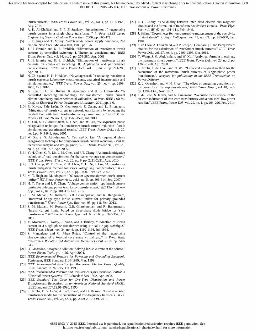
3) Validation of (12) and (15)
The analytical formulae (12) and (15) derived above for the
calculation of the optimum air-gap length and the calculation of
magnetizing current, respectively, are validated with laboratory
experiments and transient simulations next.
Some of the parameters are obtained from the open circuit
test of uncut transformer (T1). These are; λr1 = 0.54, λs = 0.59,
QOC = 7.33 var. The mitigation factor is calculated by
substitution of the parameters in (12) and varying the air-gap
length. The calculated results are compared to measurements
and transient simulations in Fig. 17. Note that, measurements
results only include 2, 4, 8, 16, 32, and 64 mil gapped
transformers. As one can observe the mitigation factors
computed by (12) are in agreement with measurements and
simulations (the maximum difference is about 7% for large
gaps). The corresponding magnetizing currents for all
transformers are shown in Fig. 17 with the comparison of (15)
and simulations (as reference, the rated current is 8.33 A). As
one can observe the magnetizing currents computed by (15) are
in agreement with measurements and simulations as well.
Fig. 17. Parametric study of (12) and (15) in terms of air-gap distance.
Note that, measurements and simulation results show that
the mitigation factor of a transformer does not change by
increasing the length of the air-gap after some point (in this case
g>2 mil). However, the magnetizing current increases with g.
Therefore, the minimum air-gap that satisfies the design
conditions should be used. We remark that gaps smaller than 2
mil are difficult to control during manufacturing.
4) Voltage Sags and Notching Examples
This section is dedicated to evaluate the effect of the
solutions on the parallel switching. To create voltage sags and
notching in the laboratory, the parallel MOSFETs of the switch
need to be activated. First, the series switch closes. After 0.5 of
a cycle the parallel MOSFETs are closed. Then to clear the fault
the parallel switches are opened.
The effect of the air-gap for parallel switching conditions is
different when compared to the voltage interruption and UPS
systems. Laboratory measurements show that even for the 64
mil transformer, the air-gap is not effective to reduce the phase-
hop currents. Similar results were found from experiments with
the unannealed transformer.
For phase-hop currents caused by parallel switching, the
only effective solution is to reduce the operating flux density at
the design stage.
VI. CONCLUSIONS
In this paper the effect of air-gaps and low-permeability iron
core materials on inrush currents has been investigated. The
following conclusions are confirmed with numerous laboratory
experiments, FEM calculations, and time domain simulations:
Air-gaps are capable of controlling the magnetizing curve
of transformers. Formulae are provided in this paper to
compute the required air-gap length for a given application.
Air-gaps are capable of demagnetizing the transformer
core when it is disconnected from the source and open
circuited.
This paper proves that the use of air gaps does not reduce
the inrush currents when transformers are fully
demagnetized.
The air gap produces a significant reduction on the inrush
currents when the transformer has residual flux, e.g. in the
phase-hop conditions. It reduces the level of the phase-hop
currents to the magnitude of the common inrush currents
when phase-hop currents are caused by interruption and
mal-function of UPS systems.
Air-gaps are not efficient mitigating phase-hop currents
caused by notching and voltage sag.
Inrush current can be mitigated to the transformer nominal
current level with a carefully designed low permeability
iron core transformer.
Low-permeability cores are effective mitigating the phase-
hop current; however, this mitigation is not as effective as
air-gap for transformers designed with the same flux
density. For the same mitigation capability, low-
permeability materials consume less active and reactive
losses (lower OPEX) and are less expensive (CAPEX is
about half).
For space or weight restricted applications where price is
not as important, air-gaps are recommended. For other
applications, low-permeability iron materials are superior
for inrush and phase-hope current mitigation.
Because the occurrence of phase-hop currents is
unpredictable, a transformer-based solution, e.g. air-gaps or
low-permeability iron core material, is needed. With these
methods, there is no need of additional control and monitoring
devices. Therefore, the proposed transformer-based solutions
are reliable, simple, and cost-effective ways to mitigate the
phase-hop currents. To avoid excessive magnetizing currents
caused by large air-gaps, the minimum gap length that can
effectively mitigate the phase-hop currents is calculated with
analytical formulae.
VII. REFERENCES
[1] L. F. Blume, G. Camilli, S. B. Farnham, and H. A. Peterson, “Transformer magnetizing inrush currents and influence on system operation,” AIEE
Trans. Power App. Syst., vol. 63, pp. 366-375, Jan. 1944.
[2] P. C. Y. Ling and A. Basak, “Investigation of magnetizing inrush current in a single-phase transformer,” IEEE Trans. Magn., vol. 24, no. 6, pp.
3217- 3222, Nov. 1988.
[3] A. Farazmand, F. de León, K. Zhang, and S. Jazebi, “Analysis, modeling and simulation of the Phase-Hop condition in transformers: The largest
0885-8993 (c) 2015 IEEE. Personal use is permitted, but republication/redistribution requires IEEE permission. Seehttp://www.ieee.org/publications_standards/publications/rights/index.html for more information.
This article has been accepted for publication in a future issue of this journal, but has not been fully edited. Content may change prior to final publication. Citation information: DOI10.1109/TPEL.2015.2459032, IEEE Transactions on Power Electronics
inrush currents,” IEEE Trans. Power Del., vol. 29, No. 4, pp. 1918-1926,
Aug. 2014. [4] A. K. Al-Khalifah and E. F. El-Saadany, “Investigation of magnetizing
inrush current in a single-phase transformer,” in Proc. IEEE Large
Engineering Systems Conf. on Power Eng., 2006, pp. 165-171. [5] K. Billings and T. Morey, Switch mode power supply handbook, 2nd
edition. New York: McGraw Hill, 1989, pp. 1-6.
[6] J. H. Brunke and K. J. Frohlich, “Elimination of transformer inrush currents by controlled switching. I. Theoretical considerations,” IEEE
Trans. Power Del., vol. 16, no. 2, pp. 276-280, Apr. 2001.
[7] J. H. Brunke and K. J. Frohlich, “Elimination of transformer inrush currents by controlled switching. II. Application and performance
considerations,” IEEE Trans. Power Del., vol. 16, no. 2, pp. 281-285,
Apr. 2001. [8] N. Chiesa and H. K. Hoidalen, “Novel approach for reducing transformer
inrush currents: Laboratory measurements, analytical interpretation and
simulation studies,” IEEE Trans. Power Del., vol. 25, no. 4, pp. 2609–2616, Oct. 2010.
[9] A. Reis, J. C. de Oliveira, R. Apolonio, and H. S. Bronzeado, “A
controlled switching methodology for transformer inrush current elimination: theory and experimental validation,” in Proc. IEEE 11th Int.
Conf. on Electrical Power Quality and Utilization, 2011, pp. 1-6.
[10] B. Kovan, F.de León, D. Czarkowski, Z. Zabar, and L. Birenbaum, “Mitigation of inrush current in network transformers by reducing the
residual flux with and ultra-low-frequency power source,” IEEE Trans.
Power Del., vol. 26, no. 3, pp. 1563-1570, Jul. 2011. [11] Y. Cui, S. G. Abdulsalam, S. Chen, and W. Xu, “A sequential phase
energization technique for transformer inrush current reduction- Part I: simulation and experimental results,” IEEE Trans. Power Del., vol. 20,
no. 2.pp. 943-949, Apr. 2005.
[12] W. Xu, S. G. Abdulsalam, Y. Cui, and X. Liu, “A sequential phase energization technique for transformer inrush current reduction - Part II:
theoretical analysis and design guide," IEEE Trans. Power Del., vol. 20,
no. 2, pp. 950- 957, Apr. 2005. [13] Y. H. Chen, C. Y. Lin, J. M. Chen, and P.T. Cheng, “An inrush mitigation
technique of load transformers for the series voltage sag compensator,”
IEEE Trans. Power Elect., vol. 25, no. 8, pp. 2211-2221, Aug. 2010. [14] P. T. Cheng, W. T. Chen, Y. H. Chen, C. L. Ni, J. Lin, “A transformer
inrush mitigation method for series voltage sag compensators,” IEEE
Trans. Power Elect., vol. 22, no. 5, pp. 1890-1899, Sep. 2007.
[15] M. T. Hagh and M. Abapour, “DC reactor type transformer inrush current
limiter,” IET Electr. Power App., vol.1, no. 5, pp. 808-814, Sep. 2007.
[16] H. T. Tseng and J. F. Chen, “Voltage compensation-type inrush current limiter for reducing power transformer inrush current,” IET Electr. Power
App., vol. 6, Iss. 2, pp. 101-110, Feb. 2012.
[17] S. M. Madani, M. Rostami, G.B. Gharehpetian, and R. Hangmaram, “Improved bridge type inrush current limiter for primary grounded
transformers,” Electr. Power Syst. Res., vol. 95, pp.1-8, Feb. 2013.
[18] S. M. Madani, M. Rostami, G.B. Gharehpetian, and R. Hangmaram, “Inrush current limiter based on three-phase diode bridge for Y-yg
transformers,” IET Electr. Power App., vol. 6, no. 6, pp. 345-352, Jul.
2012. [19] V. Molcrette, J. Kotny, J. Swan, and J. Brudny, “Reduction of inrush
current in a single-phase transformer using virtual air-gap technique,”
IEEE Trans. Magn., vol. 34, no. 4, pp. 1192-1194, Jul. 1998. [20] S. Magdaleno and C. Pérez Rojas, “Control of the magnetizing
characteristics of a toroidal core using virtual gap,” in Proc. IEEE
Electronics, Robotics and Automotive Mechanics Conf. 2010, pp. 540-
545.
[21] B. Gladstone, “Magnetic solution: Solving inrush current at the source,”
Power Electr. Tech., pp.14-26, April 2004. [22] IEEE Recommended Practice for Powering and Grounding Electronic
Equipment, IEEE Standard 1100-1999, Mar. 1999.
[23] IEEE Recommended Practice for Monitoring Electric Power Quality, IEEE Standard 1159-1995, Jun. 1995.
[24] IEEE Recommended Practice and Requirements for Harmonic Control in
Electrical Power Systems, IEEE Standard 519-1992, Apr. 1993. [25] IEEE Standard Test Code for Dry-Type Distribution and Power
Transformers, Recognized as an American National Standard (ANSI),
IEEEStandard C57.12.91-1995, 1995. [26] S. Jazebi, F. de León, A. Farazmand, and D. Deswal, “Dual reversible
transformer model for the calculation of low-frequency transients,” IEEE
Trans. Power Del., vol. 28, no. 4, pp. 2509-2517, Oct. 2013.
[27] E. C. Cherry, “The duality between interlinked electric and magnetic
circuits and the formation of transformer equivalent circuits,” Proc. Phys. Soc., vol. (B) 62, pp. 101–111, Feb. 1949.
[28] J. Billan, “Coercimeter for non-destructive measurement of the coercivity
of steel sheets”, J. Phys. Colloques, vol. 45, no. C1, pp. 965-968, Jan. 1984.
[29] F. de León, A. Farazmand, and P. Joseph, ”Comparing T and Pi equivalent
circuits for the calculation of transformer inrush currents,” IEEE Trans Power Del., vol. 27, no. 4, pp. 2390-2398, Oct. 2012.
[30] Y. Wang, S. G. Abdulsalam, and W. Xu, “Analytical formula to estimate
the maximum inrush current,” IEEE Trans. Power Del., vol. 23, no. 2, pp. 1266–1268, Apr. 2008.
[31] S. Jazebi, F. de León, and N. Wu, “Enhanced analytical method for the
calculation of the maximum inrush currents of single-phase power transformers”, accepted for publication in the IEEE Transactions on
Power Delivery.
[32] K. J. Overshott and M.H. Price, “The effect of annealing conditions on the power loss of amorphous ribbons,” IEEE Trans. Magn., vol. 18, no.6,
pp. 1394-1396, Nov. 1982.
[33] F. de León, S. Jazebi, and A. Farazmand, “Accurate measurement of the air-core inductance of iron-core transformers with a non-ideal low power
rectifier,” IEEE Trans. Power Del., vol. 29, no. 1, pp. 294-296, Feb. 2014.