investigations of the stability and heating of plasmas in ... 1958... · p/2527 ussr investigations...
TRANSCRIPT
P/2527 USSR
Investigations of the Stability and Heating of Plasmas inToroidal Chambers
By G. G. Dolgov-Saveliev, D. P. Ivanov, V. S. Mukhovatov, K. A. Razumova,V. S. Strelkov, M. N. Shepelyev and N. A. Yavlinsky*
Electrodeless discharges can be employed to pro-duce thermonuclear reactions providing that one isable to heat a long-lived stable plasma column to therequired temperature.
Some possible stability conditions have been derivedtheoretically.1 In addition experimental studies ofdischarges in chambers containing electrodes2» 3 andalso of electrodeless discharges • in toroidal cham-bers4' B» e have been performed with the purpose ofsolving these problems.
It seems quite natural to attempt to heat theplasma by Joule heating as at first glance this pos-sibility appears to be simplest and easiest, at any rateduring the first stage of formation of a plasma pos-sessing a high concentration of charged particles.
Some results of investigations of electrodeless dis-charges in deuterium are reported in the presentpaper. The experiments were carried out with tubesof various dimensions under conditions involving agreat variety of discharge parameters.
EXPERIMENTAL ARRANGEMENTS
The experiments described in the present paperwere performed with toroidal chambers of specifica-tions given in Table 1. In arrangements 1, 4 and 5 the
Table 1
No.
12
3
4
5
Dimensions in cmTorus rodáis
1520
20
SO
62.5
Material of chamber wattTube radins
58
8
13
24
QuartzCopper with two insulation sec-
tionsCopper with, two insulation sec-
tionsChromium-nickel steel with two
insulation sectionsChromium-nickel steel (without
sections)
discharge tubes were made of a dielectric or stainlesssteel and surrounded by a copper case which dampedthe long-wave oscillations of the plasma column. In
arrangements 2 and 3 the copper walls served simul-taneously as a vacuum chamber and damping sheath.Alternating as well as quasi-constant magnetic fieldscould be used in chambers 1, 3, 4 and 5 inasmuch asalong with transverse cuts each of these chambers hada longitudinal cut along the equator of the torus. Inchamber 2 only a constant stabilizing magnetic fieldcould be employed (chamber without a longitudinalcut).
The discharge was produced with the aid of a specialcoil encircling the torus. This coil will be called the 'exciting coil. In order to be able to change the initialvalues of the electric field E and the initial rate ofincrease of the current / over a broad range indepen-dently we did not employ steel cores such as those usedin our earlier work*. For the same purpose means wereprovided for connecting the capacitorsf in paralleland in series in various combinations. The voltage onthe capacitors was 5 kv and their capacity was 150 /if.
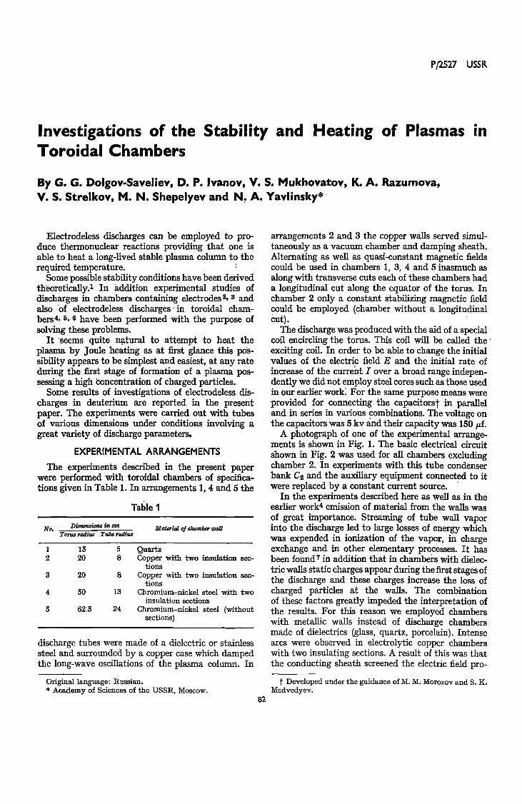
A photograph of one of the experimental arrange-ments is shown in Fig. 1. The basic electrical circuitshown in Fig. 2 was used for all chambers excludingchamber 2. In experiments with this tube condenserbank C% and the auxiliary equipment connected to itwere replaced by a constant current source.
In the experiments described here as well as in theearlier work4 emission of material from the walls wasof great importance. Streaming of tube wall vaporinto the discharge led to large losses of energy whichwas expended in ionization of the vapor, in chargeexchange and in other elementary processes. It hasbeen found7 in addition that in chambers with dielec-tric walls static charges appear during the first stages ofthe discharge and these charges increase the loss ofcharged particles at the walls. The combinationof these factors greatly impeded the interpretation ofthe results. For this reason we employed chamberswith metallic walls instead of discharge chambersmade of dielectrics (glass, quartz, porcelain). Intensearcs were observed in electrolytic copper chamberswith two insulating sections. A result of this was thatthe conducting sheath screened the electric field pro-
Original language: Russian.* Academy of Sciences of the USSR, Moscow.
82
f Developed under the guidance of M. M. Morozov and S. K.Medvedyev.
STABILITY AND HEATING OF PLASMA 83
Figure 1. General view of experimental arrangement
ducing the discharge current, and copper vapor andvapor of the insulating materials contaminated thedeuterium plasma.
Chambers having insulating sections and made ofheat-resistant chromium-nickel steel with a high elec-tric resistivity were found to be more convenient.However, spectral measurements always indicated thepresence of impurities attributable to the material ofthe insulating sections as well as to the material of thechamber walls.
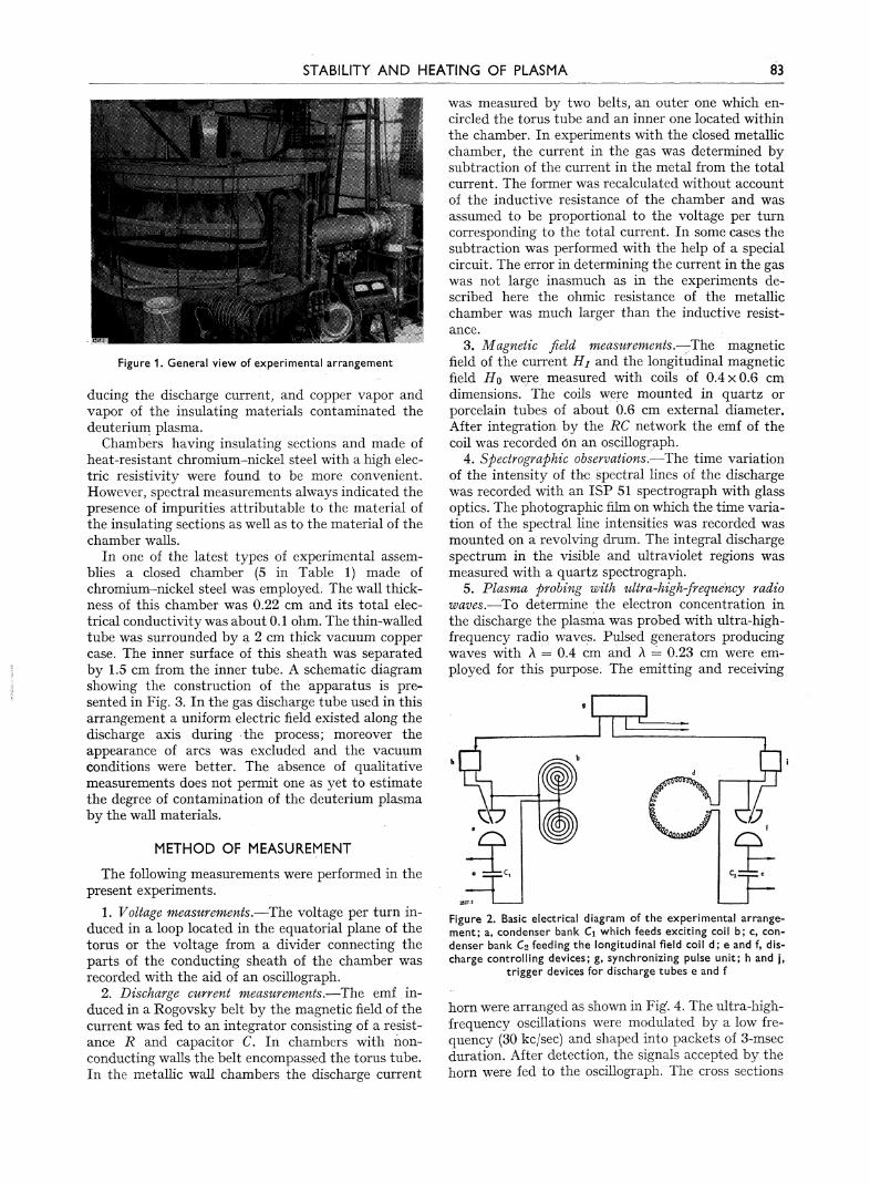
In one of the latest types of experimental assem-blies a closed chamber (5 in Table 1) made ofchromium-nickel steel was employed. The wall thick-ness of this chamber was 0.22 cm and its total elec-trical conductivity was about 0.1 ohm. The thin-walledtube was surrounded by a 2 cm thick vacuum coppercase. The inner surface of this sheath was separatedby 1.5 cm from the inner tube. A schematic diagramsnowing the construction of the apparatus is pre-sented in Fig. 3. In the gas discharge tube used in thisarrangement a uniform electric field existed along thedischarge axis during the process; moreover theappearance of arcs was excluded and the vacuumconditions were better. The absence of qualitativemeasurements does not permit one as yet to estimatethe degree of contamination of the deuterium plasmaby the wall materials.
METHOD OF MEASUREMENT
The following measurements were performed in thepresent experiments.
1. Voltage measurements.—The voltage per turn in-duced in a loop located in the equatorial plane of thetorus or the voltage from a divider connecting theparts of the conducting sheath of the chamber wasrecorded with the aid of an oscillograph.
2. Discharge current measurements.—The emf , in-duced in a Rogovsky belt by the magnetic field of thecurrent was fed to an integrator consisting of a resist-ance R and capacitor C. In chambers with non-conducting walls the belt encompassed the torus tube.In the metallic wall chambers the discharge current
was measured by two belts, an outer one which en-circled the torus tube and an inner one located withinthe chamber. In experiments with the closed metallicchamber, the current in the gas was determined bysubtraction of the current in the metal from the totalcurrent. The former was recalculated without accountof the inductive resistance of the chamber and wasassumed to be proportional to the voltage per turncorresponding to the total current. In some cases thesubtraction was performed with the help of a specialcircuit. The error in determining the current in the gaswas not large inasmuch as in the experiments de-scribed here the ohmic resistance of the metallicchamber was much larger than the inductive resist-ance.
3. Magnetic field measurements.—-The magneticfield of the current Hi and the longitudinal magneticfield Ho were measured with coils of 0.4 x 0.6 cmdimensions. The coils were mounted in quartz orporcelain tubes of about 0.6 cm external diameter.After integration by the RC network the emf of thecoil was recorded ón an oscillograph.
4. Spectrographic observations.—The time variationof the intensity of the spectral lines of the dischargewas recorded with an ISP 51 spectrograph with glassoptics. The photographic film on which the time varia-tion of the spectral line intensities was recorded wasmounted on a revolving drum. The integral dischargespectrum in the visible and ultraviolet regions wasmeasured with a quartz spectrograph.
5. Plasma probing with ultra-high-frequency radiowaves.—To determine the electron concentration inthe discharge the plasma was probed with ultra-high-frequency radio waves. Pulsed generators producingwaves with Л = 0.4 cm and Л = 0.23 cm were em-ployed for this purpose. The emitting and receiving
Figure 2. Basic electrical diagram of the experimental arrange-ment; a, condenser bank C\ which feeds exciting coil b; c, con-denser bank C2 feeding the longitudinal field coil d; e and f, dis-charge controlling devices; g, synchronizing pulse unit; h and j ,
trigger devices for discharge tubes e and f
horn were arranged as shown in Fig. 4. The ultra-high-frequency oscillations were modulated by a low fre-quency (30 kc/sec) and shaped into packets of 3-msecduration. After detection, the signals accepted by thehorn were fed to the oscillograph. The cross sections
84 SESSION A-7 P/2527 G. G. DOLGOV-SAVELIEV et al.
2527.3
Figure 3. Schematic diagram of experimental arrangement: a, eoll for excitation of a vortex electricfield; b, copper shield for reduction of scattered fields; c, longitudinal magnetic field coll; d, copperstabilizing coil; e, thin-walled vacuum chamber made of a high-resistivity alloy; f and g, nipples forevacuation of the chamber and forechamber; h, observation window (for photography, ultra-high-
frequency probing, spectral measurements, adjustment of measuring belts and magnetic probes)
of the waveguide channel, and the emitting and receiv-ing horns, were made circular in order to ensure trans-mission of the oscillations through the plasma whichwas crossed by helical Unes of force of the magneticfield.
6. Photography of the discharge glow was done with ahigh-speed photographic recorder. The photographsgive the time variation of the glow intensity of thegas discharge in the plane of the observation window(see Fig. 3).
MEASUREMENTS
1. Stray Field
Our experimental arrangement was essentially anair transformer whose secondary coil consisted of agas loop. In systems of this type the stray field Hz ofthe primary coil reaches very high values. The stabiliz-ing, conducting 2-cm-thick sheath reduced the strayfields considerably. The sheath had four sections—two with insulating slugs and two constructive sec-tions with metallic slugs. Stray fields permeated thesesections. Moreover, the current flowing in the closed
metallic sheath which served as the discharge chamberalso produced a vertical magnetic field component.
In order to reduce the magnitude of this verticalcomponent a copper shield was interposed in the dis-charge chamber between the exciting coil and thetorus. The vertical component of the field produced bythe current flowing in the chamber could be somewhatreduced by arranging the copper stabilizing sheathnear the thin-walled case of the chamber and by fixingthe latter in an eccentric position with respect to theconducting surfaces.
Curves characterizing the maximal field strengthsHz along the toroidal axis before and after assembly ofthe shield are shown in Fig. 5. It should be noted thatwith increase of the reference frequency of the circuitthe penetration of scattered fields into the shield de-creases. Since under the conditions of our experimentsthe role of the active resistance of the plasma loop wasalways important, the peak of the magnetic fieldstrength Нг was shifted by a certain angle with re-spect to the peak of the current.
Decrease of the magnitude of the scattered fields led

STABILITY AND HEATING OF PLASMA 85
to an improvement in the conditions for formation ofa discharge. Thus with a charge voltage of 15 kv a dis-charge could be induced in deuterium at a pressure of10~3 mm Hg without a high-frequency source for pro-duction of initial ionization. Moreover, destruction ofthe plasma column after decrease of the current in itproceeded at a slower rate. A purely ohmic dischargeprocess was observed when the stray field strengthwas large. In this case the voltage per turn and currentin the gas passed through zero simultaneously. Underthe same conditions the presence of the shield led tothe result that the current was somewhat delayed (by100-150 j sec) with respect to the voltage.
2. Discharges In Strong Magnetic FieldsOn the basis of the data reported in Ref. 4 one may
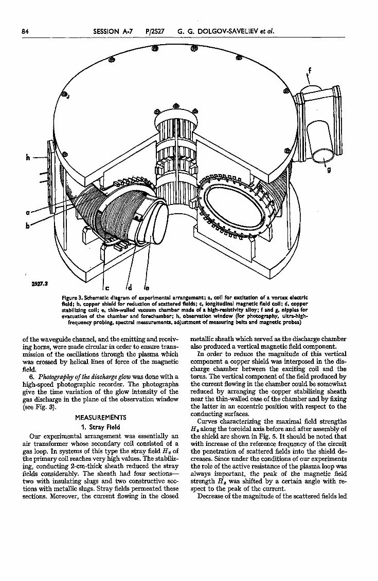
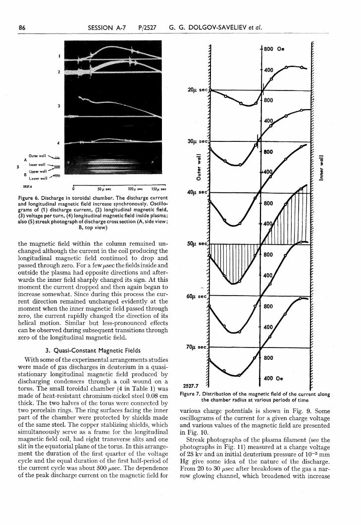
presume that heating of a plasma produced in astrong magnetic field (Hi 4. Ho, where Ho is thelongitudinal magnetic field strength and Hi is the dis-charge current magnetic field strength) is limited bytwo factors—by the strong interaction with the cham-ber walls and by loss of hydrodynamic stability.Under conditions when the plasma fills the whole crosssection of the chamber, instability can be inferredfrom indirect observations. It would seem to be profit-able to investigate the possibility of formation, in astrong magnetic field, of a plasma column whichinteracts weakly with the walls. With this aim in mindthe following investigations were carried out in atoroidal chamber made of quartz: (1) Elucidation ofthe conditions under which the discharge current andlongitudinal magnetic field vary synchronously. (2) In-vestigation of conditions under which the frequency ofvariation of the longitudinal magnetic field exceeds byseveral times the reference frequency of the dischargecurrent! Measurements under conditions of a syn-chronously increasing field were carried out at a peaklongitudinal magnetic field strength up to 5000 gaussand discharge currents up to 25 ka. Oscillograms ofthe voltage per turn, of the discharge current and ofthe longitudinal magnetic field strength are presentedin Fig. 6. Beneath the oscillograms a streak photo-graph of the discharge is presented, which was takensimultaneously through the side and top slits in thecopper stabilizing sheath. The time scales of the streakphotograph and oscülogram are identical. The dis-charge current in this experiment attained 18 ka andthe longitudinal magnetic field 3.5 kilogauss. The dis-tribution of the field strength Hi at successive periodsof time as measured with the aid of magnetic probesis shown in Fig. 7. It follows from these data that thedischarge begins to develop in the center of thechamber (as observed in experiments in the absenceof a longitudinal field) and subsequently spreadscompletely over the cross section of the chamber.
Measurements of the current distribution over thechamber cross section carried out with a small coil(magnetic probe) indicated that although the currentaxis was displaced towards the inner wall of the cham-ber, some contraction of the discharge filament didoccur. After the current attained its peak value the
distribution of the current density over the cross sec-tion became more uniform.
In experiments involving a rapidly increasing fieldand the same chamber the duration of the first quarterof the discharge cycle was 145 j¿sec and the frequencyof variation of the longitudinal magnetic field was15,000 c/sec. In Fig. 8 we present oscillograms of (1)the discharge current, (2) variation of the current inthe coil producing the longitudinal magnetic field, (3)voltage per turn of the chamber, and (4) magneticfield strength in the center of the chamber measuredwith a magnetic probe ; and also (5) a streak photographof the discharge. After 20/asec the current attainsa value of about 5 ka. At this moment the longi-tudinal magnetic field is turned on. As a result, therate of increase of the current approximately doubles.After 30 jLtsec the current in the longitudinal field coilreaches its peak value. However, the discharge currentcontinues to increase and reaches 22 ka. When thethe current in the longitudinal field coil vanishes, thelongitudinal magnetic field frozen in the plasmapersists there for 6-8 /¿sec. The strength of the longi-tudinal field along the chamber axis remains approxi-mately equal to that of the magnetic field of the cur-rent at the boundary of the plasma column.
A comparison of the streak photograph with theoscillograms reveals that the column contracted by 4to 5 times; simultaneously the voltage increased and
Figure 4. Diagram of device for ultra-high-frequency probing ofthe plasma; a, generator; b, emitter; c, receiving horn; d, detec-
tor; e, oscillograph and amplifier
300
200
I\\\\
\\I
4я . — -
• •.
— !
90cmIniulcted
gap
Пса QObservation
wind»»
Figure 5. Peak values of vertical component of magnetic field alongaxis of toroidal tube. Charge voltage 5 kv. Frequency f = 220c/sec. Curve 1, before incorporation of shield; curve 2, after
incorporation of shield
86 SESSION A-7 P/2527 G. G. DOLGOV-SAVELIEV et al.
О 50 ц sec 100/z sec 150/x sec
Figure 6. Discharge in toroidal chamber. The discharge currentand longitudinal magnetic field increase synchronously. Oscillo-grams of (1) discharge current, (2) longitudinal magnetic field,(3) voltage per turn, (4) longitudinal magnetic field inside plasma;also (5) streak photograph of discharge cross section (A, side view ;
B, top view)
the magnetic field within the column remained un-changed although the current in the coil producing thelongitudinal magnetic field continued to drop andpassed through zero. For a few/xsec the fields inside andoutside the plasma had opposite directions and after-wards the inner field sharply changed its sign. At thismoment the current dropped and then again began toincrease somewhat. Since during this process the cur-rent direction remained unchanged evidently at themoment when the inner magnetic field passed throughzero, the current rapidly changed the direction of itshelical motion. Similar but less-pronounced effectscan be observed during subsequent transitions throughzero of the longitudinal magnetic field.
3, Quasi-Constant Magnetic Fields
With some of the experimental arrangements studieswere made of gas discharges in deuterium in a quasi-stationary longitudinal magnetic field produced bydischarging condensers through a coil wound on atorus. The small toroidal chamber (4 in Table 1) wasmade of heat-resistant chromium-nickel steel 0.08 cmthick. The two halves of the torus were connected bytwo porcelain rings. The ring surfaces facing the innerpart of the chamber were protected by shields madeof the same steel. The copper stablizing shields, whichsimultaneously serve as a frame for the longitudinalmagnetic field coil, had eight transverse slits and oneslit in the equatorial plane of the torus. In this arrange-ment the duration of the first quarter of the voltagecycle and the equal duration of the first half-period ofthe current cycle was about 500 /¿sec. The dependenceof the peak discharge current on the magnetic field for
20ft sec
30ft sec;
эО
40/z sec
50ft sec'
60ft sec^
70ft
800 Oe
400
\
f
800
800
400>
800
400 Oe2527.7
Figure 7. Distribution of the magnetic field of the current alongthe chamber radius at various periods of time
various charge potentials is shown in Fig. 9. Someoscillograms of the current for a given charge voltageand various values of the magnetic field are presentedin Fig. 10.
Streak photographs of the plasma filament (see thephotographs in Fig. 11) measured at a charge voltageof 25 kv and an initial deuterium pressure of 10~3 mmHg give some idea of the nature of the discharge.From 20 to 30 /¿sec after breakdown of the gas a nar-row glowing channel, which broadened with increase

STABILITY AND HEATING OF PLASMA 87
of the current, appeared on the background of a weakdiffuse glow in the chamber. This luminous region pul-sated and had protuberances which reached the cham-ber walls. With increase in the initial magnetic fieldthe luminous channel became broader and the burstsbecame more regular although their brightness de-creased. With further increase in the longitudinal mag-netic field the plasma began to fill up the wholechamber volume. The inhomogeneity and disorder ofthe glow impedes interpretation of the photographsunder these conditions.
More detailed investigations of the constrictedplasma column were made at various durations of theprocess in a chamber whose tube diameter was 47 cmand torus diameter 125 cm. Oscillograms of the totalcurrent in the secondary circuit and of the voltage perturn are presented in Fig. 12 for frequencies of 220 c/secand 750 c/sec. The calculated values of the current inthe gas are given on the oscillograms. It should benoted that for a frequency of 770 c/sec the peak currenton the second half-wave exceeds that on the first half-wave. Under the conditions we have used, the peakdischarge current continued to depend linearly on theelectric field. The dependence of the peak dischargecurrent on the magnetic field strength is linear and forthis chamber does not differ from the dependence pre-sented in Fig. 8 for the chamber with a tube diameterof 26 cm.
Streak photographs of the discharge are shown inFig. 13. These photographs were taken when the dura-tion of the first quarter of the voltage period was about1 /¿sec.
The glowing discharge column in the center of thechamber had a uniform and fibrous structure. Thewavelike shape indicates that the column as a whole
50 (i sec 150/x sec
Figure 8. Discharge in toroidal chamber. Rapidly increasinglongitudinal field. Oscillograms of (1 ) discharge current, (2) longi-tudinal magnetic field (mean value), (3) voltage per turn, and (4)longitudinal magnetic field in center of chamber; also (5) streakphotograph of cross section of discharge (A, top view; B, side
view)
300
200
100°y
о s*
y
*****
y0
yAT
^ ***
2.527.9
1000
Magnetic f ield, с
2000 3000
irsted
Figure 9. Dependence of peak current on longitudinal magneticfield for various charge voltages
200
cu
rre
nt,
kA
Dis
ch
arg
e
/
yCУ^*~
4000 Oe
2200 Oe"•- —i
1300 Oe
800 Oe««mm
v
— ' —1
2527.1»
\
Tin,., „ sec ° U w
Figure 10. Oscillograms of discharge current for various values oflongitudinal magnetic field
oscillates in a vertical plane without touching thechamber walls. Throughout the process a glow of thegas is observed. At certain moments the brightness ofthe glow increases.
Of undoubted interest is a photograph of thecolumn which refers to the second half-period of thecurrent. Regularly spaced helical luminous bands arewound around a central core which oscillates with afrequency smaller than that during the first half-period. The amount of light at the time is much smallerthan that during the first half-period of the current.
Comparision of streak photographs made for var-ious values of the longitudinal magnetic field showsthat under our conditions (presence of stray magneticfields Hz of about 100 gauss along the toroidal axis)stability is impaired with decrease of the longitudinalmagnetic field and the duration of the column is re-duced. The lower streak photograph in Fig. 13 cor-responds to Ho = 1300 gauss and' gives some ideaabout the course of the process during the first andpart of the second half-period of the current. Thisphotograph differs from the previous one (Ho = 900

88 SESSION A-7 P/2527 G. G. DOLGOV-SAVELIEV et al.
H -lOOOoe
H. =1500oe
250 500^ sec
Ho =5000oe
2527. И 0 250 500^ secFigure 11. Streak photographs of plasma filament. The chamber boundaries are designated by white lines
У
V
500 n sec 1000/£ sec 2527.12 0 1000 ¡i sec 2000/x sec
Figure 12. Oscillograms of the total current in the secondary circuit, of the current in the gas andof the voltage per turn for U = 15 kv, Ho = 400 gauss, po = 3x10~3 mm Hg; 1, current in chambersheath (gas current is zero) and voltage per turn; 2, total current, gas current and voltage perturn; 3, current in chamber sheath (gas current is zero) and voltage per turn; 4, total current,
gas current and voltage per turn

STABILITY AND HEATING OF PLASMA 89
H = 300oe
500oe
2S&.it\
900oe
H = 1300oe
0 500/i sec 1000/i sec 1500ft sec
Figure 13. Streak photograph of plasma filament. The chamber boundaries are indicated by white lines
2000Ц sec
gauss) in that the discharge column is shifted down-ward relative to the chamber axis during the firsthalf-period and shifted upward during the secondhalf-period. The plasma column depicted on thisphotograph at the moment the current attained itspeak value has a smaller diameter. Finally duringthe second half-period of the current the amplitudeof the column oscillations is greater than that of theoscillations during the first current half-period.
From the streak photograph one can derive the timevariation of the radius of the discharge column. How-ever, various measurements and in particular thosereported in Ref. 3 indicate that the current distribu-tion over the cross section may be inferred fromthe light measurements. The ''current" radius, i.e.,the current distribution over the chamber cross sec-tion derived from mean weighted quantities, is alwayssmaller than the radius determined from the streakphotographs. The dependence of the conductivity ofthe discharge column on the longitudinal magneticfield is presented in Fig. 14. The conductivity wascomputed from the discharge current and from the
10-10»-*
8 - 1 0 "
4-10U •
M O 1 4
4V I
V 42 N
a127 14
1000 2000 3000
Longitudinal magnetic field, Oe
Figure 14. Dependence of plasma conductivity on longitudinalmagnetic field; 1, for a torus with a tube diameter of 26 cm;
2, for a torus with a tube diameter of 47 cm
electric field strength at the moment when the latterattains its maximum. Curve 1 refers to a chamberwith a tube diameter of 26 cm and curve 2 to a cham-ber of 47 cm diameter. Since the difference betweenthese curves is smaller than the experimental errors,it may be concluded that in the experiments describedin this paper the conductivity depends weakly on thechamber dimensions. If one takes into account that the"light" radius used in the calculations is greater thanthe "current" radius and also that the current densityalong the discharge axis is very considerable, themaximal plasma conductivity may be estimated toequal o- = 1015 cgse.
The time of appearance of spectral lines emitted bythe wall material can be roughly determined from thestreak photographs. For illustration a streak photo-graph of the spectrum is presented in Fig. 15. Ex-amination of phototgraphs made under variousconditions shows that the impurity lines appear afterthe lines emitted by deuterium. At a reference fre-quency of 770 c/sec the lines due to the wall materialappeared after 100 /xsec when the current peak was150 ka and after 200-220 /xsec when the current peakwas 85 ka. For a frequency of 220 c/sec and / m = 110 kathe Fe, Cr and Ni lines appeared after 80-100 /¿sec.
The spectra photographed with the quartz spectro-graph contain lines which persisted during the entiretime the current flowed through the gas. Thesespectra are characterized by the deuterium lines, bythe presence of lines emitted by multiply ionized im-purity atoms (O, N) and by the presence of intenseFe, Cr and Ni lines.
Radiofrequency oscillations of a frequency of75,000 and 130,000 Mc/sec were used to determinethe concentration of the charged particles in theplasma.
Ultra-high-frequency oscillations of 0.23 cm wave-length (130,000 Mc/sec) were completely reflected bythe plasma formed in a torus at an initial deuterium

90 SESSION A-7 P/2527 G. G. DOLGOV-SAVELIEV et al.
Fe
Cr
Dy
=4248 A
=4248 A
Fe À=4800 A
Fe À=5686 A
Doc
500 1000fi sec
Figure 15. Streak photograph of discharge spectrum. Uch = 15 kv, H = 800 gauss, p0 = 3 x 10~3 mm Hg
pressure of 10~3 mm Hg. The amplitude of the re-corded signal was much smaller at lower initial pres-sures. When po was reduced still further the recordedsignal did not differ from that passing through aneutral gas. Some oscillograms referring to the passageof ultra-high-frequency oscillations through a plasma(1) and reflection of the oscillations (2) are shown inFig. 16. The second trace is a record of the dischargecurrent. The experimental data available to us are notsufficient, however, to permit us to draw any unam-biguous conclusions. The information derived fromstreak photographs of the discharges indicates thatfrom 40 to 60% of the magnetic field is captured dur-ing the contraction process. If one assumes that in theinitial stage of the discharge an equal fraction ofparticles is captured, this would mean that ionizationin the discharge column is almost complete. If alarger number of particles were captured by the fieldthe degree of ionization would be correspondinglylower.
It should be mentioned that even when the oscilla-tions are completely reflected during the first half-period of the current a signal transmitted by theplasma will almost always be recorded during thesecond half-period. Evidently impurities emitted fromthe walls not only cool the plasma but also lead to adecrease of the concentration of the charged particles.
CONCLUSIONS
The experimental data presented above permit oneto draw the following conclusions:
1. The plasma compressed by the current detachesfrom the walls and forms a column. Capture ofthe magnetic field is not complete and in our experi-ments does not exceed 60% of the initial field.
2. The observed macroscopic oscillations of the
Signal uhf
Signal uhf
Figure 16. Oscillograms of modulated uhf signal and current;1, transmission of uhf signals through plasma; 2, reflection of uhf
signals from plasma

STABILITY AND HEATING OF PLASMA 91
plasma column do not permit one to consider that itis fully stable; there is even less reason to suppose thatit does not interact with the walls.
3. The conductivity of the plasma column ob-served in the present experiments does not exceed1016 cgse, which corresponds to an electron tempera-ture of 15-30 ev. Evidently higher plasma conduc-tivities were also not achieved in other arrangementsof a similar type.
4. The energy transferred to the chamber walls by
particles and radiation during the existence of theplasma column should be measured and the effect ofimpurities on heating of the deuterium plasma shouldbe determined.
ACKNOWLEDGEMENTS
The authors wish to thank L. A. Artsimovich andM. A. Leontovich for their attention to this work andfor numerous fruitful discussions.
REFERENCES
1. V. D. Shafranov, Atomnaya Energ., 1, No. 5, 38 (1956)Collection of papers on Plasma Physics and the Problem ofThermonuclear Reactions, Vol. 2, p. 130.
2. A. L. Bezbatcbenko, I. N. Golovin, D. P. Ivanov, V. D.Kirillov and N. A. Yavlinsky, Atomnaya Energ., 1, No. 5,26 (1956).
3. I. N. Golovin, D. P. Ivanov, V. D. Kirillov, P. P. Petrov,K. A. Razumova and N. A. Yavlinsky, Stable PlasmaColumn in a Longitudinal Magnetic Field, P/2226, Vol. 32,these Proceedings.
4. A. L. Bezbatchenko, I. N. Golovin, P. I. Kozlov, V. S.Strelkov and N. A. Yavlinsky, Collection of papers on
Vol. 4, p. 169.5. P. С Thonemann, E. P. Butt, R. Carruthers, A. N. Dellis,
D. W. Fry, A. Gibson, G. N. Harding, R. W. McWhirter,D. J. Lees, R. S. Pease, S. A. Ramsden and S. Ward,Nature, 181, 217 (1958).
6. N. L. Allen, T. E. Allibon, D. R. Chick, R. F. Hemmings,T. P. Hughes, S. Kaufman, B. S. Liley, J. G. Mack, H. T.Miles, R. M. Payne, J. E. Read, A. A. Ware, J. A. Wessonand R. V. Williams, Nature, 181, 222 (1958).
7. A. L. Bezbatchenko, I. N. Golovin and O. P. Ivanov, un-published work.