invitation for pre tender meet€¦ · brief scope and description of the package and the flow...
TRANSCRIPT

INVITATION FOR PRE TENDER MEET
Name of Client: Assam Bio Refinery Project Ltd. (Client/Owner) Name of Project: Bio Refinery Project at Numaligarh, Assam, India.
Name of Work: Raw Bamboo Handling Package
Brief Scope of Work: Raw Bamboo Handling Package. Overview of the process is as follows:-
a) Raw Bamboo arrives inside plant in Truck. b) Bamboo is unloaded by Log stacker/unloader. c) Bamboo is stacked in open storage area. d) Log stacker / unloader unloads the bamboo on to the conveyor (part of raw bamboo handling
package) e) Processed bamboo chips are fed to the top of Batch Digester vessels (by others)
Brief Scope and description of the package and the Flow diagram is as per Annexure-1
KEEPING ABOVE IN MIND, A PRE-TENDER MEETING HAS BEEN SCHEDULED AND DETAILS OF PRE-TENDER MEETING ARE AS FOLLOWS
1. Venue Engineers India Limited Business Centre, Room No. 4, Tower-1 EIL Office Complex, Sector – 16 (on NH-8), Gurugram -122001
2. Date & Time of Meeting At 1000 HRS (IST) onwards on 10th Jan 2019
3. Contact Person 1) Anindya Sinha, DGM (SCM): e-Mail ID: [email protected] Tel.: 0124 380 2103
2) Abhishek, Manager (SCM): e-Mail ID: [email protected] Tel.: 0124 380 2175
4. Purpose of Meeting: Introduction of Project to bidders
Understanding capability of bidders (i.e experience of supply and installation of such package in Paper/Pulp/Biomass industry)
Resolution of bidders query
5. Time schedule 14 Months
6. Project Location and Connectivity
Numaligarh, Assam (Nearest Airport : Jorhat ;Nearest Railway station : Numaligarh Railway station)

Agencies are requested to submit the details (Experience & Financial) in the enclosed Annexures -2 to the e-mail ids mentioned in this notice positively by 09th Jan 2019 and are also requested to bring along with them their Experience Record (along with documentary evidences) for similar kind of works and the complete audited annual FY Statements of the immediate preceding 3 FYs. Note: Prospective bidders are requested to depute their competent representatives for the meeting.
Encl.
1. Annexure 1- Scope of Work Document. 2. Annexure 2- (Format for Technical Experience/ Format for Financial details)

ANNEXURE-1

BRIEF WRITE UP of
RAW BAMBOO HANDLING PACKAGE
Page 1 of 4
Format No. EIL-1641-1924 Rev.1
Copyright EIL – All rights reserved
1.0 SYSTEM DESCRIPTION AND MATERIAL CHARACTERISTICS
1.1 General
1.1.1 Raw bamboo handling package shall consist of raw bamboo log receiving and handling; chipping, storage and feeding of chipped bamboo to fractionation process. The raw bamboo arrives to the bio-refinery in trucks / rail wagons in three forms: round, flattened and chipped. In all the cases they are coming to the same handling area. The unchipped (round/ flattened) portion will be 70% and the chipped portion 30 % of total delivered amount.
1.1.2 Conveying system shall be capable to transfer the material at the design rate from Bamboo receipt up to Chip Silo and further to downstream fractionation section.
1.1.3 Tentative arrangement of the equipment / system associated with raw bamboo handling package, is indicated in the Overall Layout of Raw Bamboo Handling Package (Drg. No. B215-000-80-43-00001). The system shall be designed to receive the raw materials at grade level and to transfer the same to the downstream digester package (Digester package by others) at about 30 m above the Grade.
1.1.4 Electronic belt scales shall be provided on belt conveyors 0105-CB-0005, 0105-CB-0013 & 0105-CB-0014.
1.1.5 Maintenance facilities viz. electric wire rope hoist, chain pulley blocks etc. complete with accessories and associated facilities such as Geared trolley, monorail beam etc. shall be supplied wherever required for maintenance of Contractor’s supplied equipment.
1.1.6 Each shed shall have one no. floor cleaning chute connecting all floors.
1.1.7 Dry Fog type Dust Suppression System shall be provided at following location to control dust generation.
Chipper house 1 & 2 Chip Scalper Screen house Bamboo Chip Storage
Bamboo Feed Handling Shed
Sprinkler type Dust Suppression System shall be provided at stone discharge end of Stone Separator conveyor (0105-CB-0010).
1.1.8 The entire raw bamboo handling package i.e. raw bamboo log receiving and handling; chipping, storage and feeding of chipped bamboo to fractionation process, shall be complete in all respects with necessary electrical and instrumentation so as to enable the operators to operate the entire system from Substation and Control Room located at a tentative distance of 240m from the Chipper House 1 & 2. Package PLCs of Raw bamboo handling package installed in Substation and Control Room shall control all its operation with simultaneous communication with the DCS of the Plant for start/stop permission, alarm reporting, trip indications etc. All necessary interlocks shall be provided for safe operations of the coke handling system.
1.1.9 To avoid chip laden water going into surrounding area, drain shall be provided at around all sheds i.e.
Bamboo receiving pocket
Chipper House 1 & 2

BRIEF WRITE UP of
RAW BAMBOO HANDLING PACKAGE
Page 2 of 4
Format No. EIL-1641-1924 Rev.1
Copyright EIL – All rights reserved
Chip Scalper Screen house Bamboo Chip Storage Bamboo Feed Handling Shed
1.1.10 Sizes of sheds and levels of conveyors shown in the conceptual drawings / layout are minimum requirements. The same may be increased by Contractor during detail engineering if required. The same shall be implemented by contractor accordingly without any time and price implication.
1.1.11 This specification shall be read in conjunction with following reference documents (attached with this document):
Flow Diagram of Raw Bamboo Handling Package Overall Layout of Raw Bamboo Handling Package (Drg. No. B215-000-80-43-0001)
1.2 Feed Material Characteristics
1.2.1 The characteristics / properties of the raw material received at site are as given below:
Material handled Round Bamboo / Bamboo Chips Length of round bamboo 7 feet (2.1m) Diameter of round bamboo 3 – 4 inch Solid Density of round bamboo (kg/m3)
~400
Chip Size (at the Chip receiving pocket)
Max. 25 mm
Bulk Density (kg/m3) of chips to be considered for system design
200 (for volumetric design) / 250 (for structural / mechanical design and drive sizing)
Temperature Ambient
Moisture,% <20
Pentosans >21 % on dry matter
Ash <4 % on DM
Acetic acid as acetyl group > 3.7 % on DM
Chip Size (at the Chip receiving pocket)
Max. 25 mm
Angle of Repose of Chip, degree ~30
Angle of Surcharge of Chips, degree
~25
1.3 Bamboo Log Receiving and Handling
1.3.1 Logs are unloaded from vehicles with log stackers or with front-end loaders. Unloaded logs are transferred either to the log storages or to the process. If log handling process is not running for some reason (mechanical failure, chip storage is full etc.) logs are stored to the log storage. Log storage is located near to unloading area.
1.3.2 Front-end loaders or log stackers feed the bamboo logs to the conveyors 0105-CB-0001 and 0105-CB-0002. Conveyors feed the logs to the chipper 0105-SH-0002 (0105-SH-0003) feeding roller system. This system squeezes the bamboo logs closely together and feeds them to the chipper. Feeding system consist of hydraulic feeding rollers both above and below of the log bundle and a compression cylinder.
1.3.3 Conveyors feeding bamboo logs to chippers (Tag Nos. 0105-CB-0001 and 0105-CB-0002) shall have adequate length to place minimum Five (5) bamboo bundles length wise.

BRIEF WRITE UP of
RAW BAMBOO HANDLING PACKAGE
Page 3 of 4
Format No. EIL-1641-1924 Rev.1
Copyright EIL – All rights reserved
1.3.4 Chips from chip silo are discharged to the process with a speed controlled discharging screw. The set point to the screw control comes from digester batch sequence control.
1.3.5 Logs which are going straight to the process are fed either to the chipping line 1 or 2. Chipping lines are similar and they are working in parallel. One chipping line can produce all the chips for the process needs. Chipping lines can work in the simultaneously or one at a time. Chipping capacity is based on working form 2/7 where chipping is working seven days per week and two 8 hour shifts per day.
1.3.6 Chipper 0105-SH-0002 (0105-SH-0003) is drum type with adequate number of knives. Infeed system push the bamboo bundle against the cylinder and knives cut the bamboo logs into the certain length of chips. Chipper shall be designed to produce chips of 25 mm dimension. Af ter cutting chips are led to the belt conveyor 0105- CB-0006.
1.4 Chip receiving and handling
1.4.1 Approx. 30 % of raw material (bamboo) will be received as chips. Chips transported by trucks are fed directly to the chip receiving pocket 0105-TH-0001 (Approx. 5 m long, 5 m wide and 2m deep). In the bottom of the chip receiving pocket there is a discharging screw system. The number of screws may vary from one to three. Discharging screw/s feed chips to a belt conveyor 0105-CB-0005 which feed them to a scalper screen (0105-SS-0001).
1.4.2 Scalper screen (0105-SS-0001) shall be a disc screen with large opening between discs. Typically spacing between discs can vary from 40 to 80 millimetres. Purpose of the screen is to separate large impurities as stones, metal pieces etc. from incoming chip flow. Accepted chips go through the screen and rejected material is led near the screen into the pile or to the container.
1.4.3 Chip flow from belt conveyor 0105-CB-0003/0004 from the chippers and accept flow from scalper screen is led to the belt conveyor 0105-CB-0006. This conveyor conveys the chips to a shuttle belt conveyor 0105-CB-0007 which feed the chips to the chip storage.
1.5 Chip storage
1.5.1 The chip storage is longitudinal type and it has a triangle type cover round it. The feeding shuttle belt conveyor (0150-CB-0007) is located in the top of the cover. Volume of the storage is 25000 loose-m3 (tentatively 90m long X 50m wide) having approx. 5 days storage of production.
1.5.2 The shuttle belt conveyors 0105-CB-0007 length is about half of the discharging area length. This Conveyor shall move above the discharging area and drops the chips down in one place at a time. When this place is full, conveyor shall move either about 0.5 - 1 meter forward or back. When half of the storage is full, conveyor changes the rotation direction and starts to fill the other side of the storage with the same method.
1.5.3 Screw Reclaimers 0105-CS-0002 and 0105-CS-0003 under the storage are discharging chips to a chip screen feeding belt conveyor system. Typically both screws are working all the time and both of them are discharging half of the needed amount of chips. The screws are dimensioned in such a way that each screw can feed the required amount of chips to the screening. Screws rotating speeds are adjustable and set point to the speed is given from the level of the chip feeding silo 0105-TI-0001.
1.6 Chip screening
1.6.1 Chips are led from discharging screws via belt conveyors 0105-CB-0008A/B and 0105-CB-0009 to a stone separator conveyor 0105-CB-0010.
1.6.2 The stone separator conveyor 0105-CB-0010 is a belt conveyor with an adjustable rising angle. Chip flow from previous conveyor 0105-CB-0009 is fed to the beginning of the stone separator conveyor. When the angle of the conveyor is suitable, stones and other heavier

BRIEF WRITE UP of
RAW BAMBOO HANDLING PACKAGE
Page 4 of 4
Format No. EIL-1641-1924 Rev.1
Copyright EIL – All rights reserved
pieces will bounce away from the conveyor and chip flow will continue to the screening. Stone separator conveyor feed the chips to the belt conveyor 0105-CB-0011. This conveyor feeds the chip flow to the chip screen 0105-SS-0002.
1.6.3 Cross belt Overband Magnetic Separator (0105-SM-0001) shall be provided on stone separator conveyor 0105-CB-0010 for separation of metallic particles from chip.
1.6.4 Metal detector (Tag No. By Contractor) shall be provided on the stone separator conveyor, downstream of the Magnetic Separator. This Metal Detector will give an alarm on detecting metal so that the operator can stop the conveyor and remove metal manually.
1.6.5 In a gyratory chip screen (0105-SS-0002) there is a shaft in the middle of the screen. It gives the box a freely vibrating circular motion on the horizontal plane. Typical amplitude is 50-60 mm. The chips are fed in a continuous flow to a feeding trough at the top of the screen. From the trough the chips fall to upper deck. Oversize chips remain on the upper deck and fall into the overflow trough at the discharge end to a bin. Oversized chips are fed to the shredder 0105-SH-0001. Shredder's rotating blades cut the oversized chips smaller. The processed chips are fed back to screening (0105-SS-0002) at suitable location. Transfer of Oversized chip from Chip screen to shredder shall be conceptualized by contractor based on selection of Chip screen and shredder feeding mechanism during detail engineering.
1.6.6 Accepted chips are discharged over the edge of the middle screening decks to conveyor 0105-CB-0013. Dust passes through all decks and collects on the bottom plate of the screen for removal by conveyor 0105-CB-0007 to a separate dustbin near the screen house. The dustbin can be loaded to a truck.
1.7 Chip feeding to process
1.7.1 Accepted chips from screening are led to the silo 0105-TI-0001 with a belt conveyor 0105-CB-0013. The conveyor is equipped with a belt scale. Chip silo 0105-TI-0001 shall have a useful volume of minimum 500 loose-m3. Level of the silo is measured with a level transmitter. The level controls the rotation speed of the chip storage discharging screws and hence the chip screen feed capacity.
1.7.2 Chips from silo are discharged to the process with a speed controlled discharging screw 0105-CS-0001. The set point to the screw control comes from digester batch sequence control. The same measurement gives also a set point to speed control of the belt conveyor 0105-CB-0014. Capacity of process feeding shall be variable depending on the desired digester fill time.
1.7.3 Chip from silo shall be analyzed for moisture content by Online Moisture Analyzer. Moisture analyzer shall be located near the discharge point of Chip Silo.
1.7.4 Conveyor 0105-CB-0014 feeds chips from the silo 0105-TI-0001 to the screw conveyor 0110-CS-0002-A (supply by others). When digester is full of chips, control system stops the chip feeding chain from the chip silo's (0105-TI-0001) Discharge Screw (0105-CS-0001) to Screw conveyor 0110-CS-0002-A to. When the next digester's chip filling starts, control system starts first the screw conveyor 0110-CS-0002-A into desired direction and after that rest of feeding chain conveyors up to the silo discharger screw 0105-CS-0001.


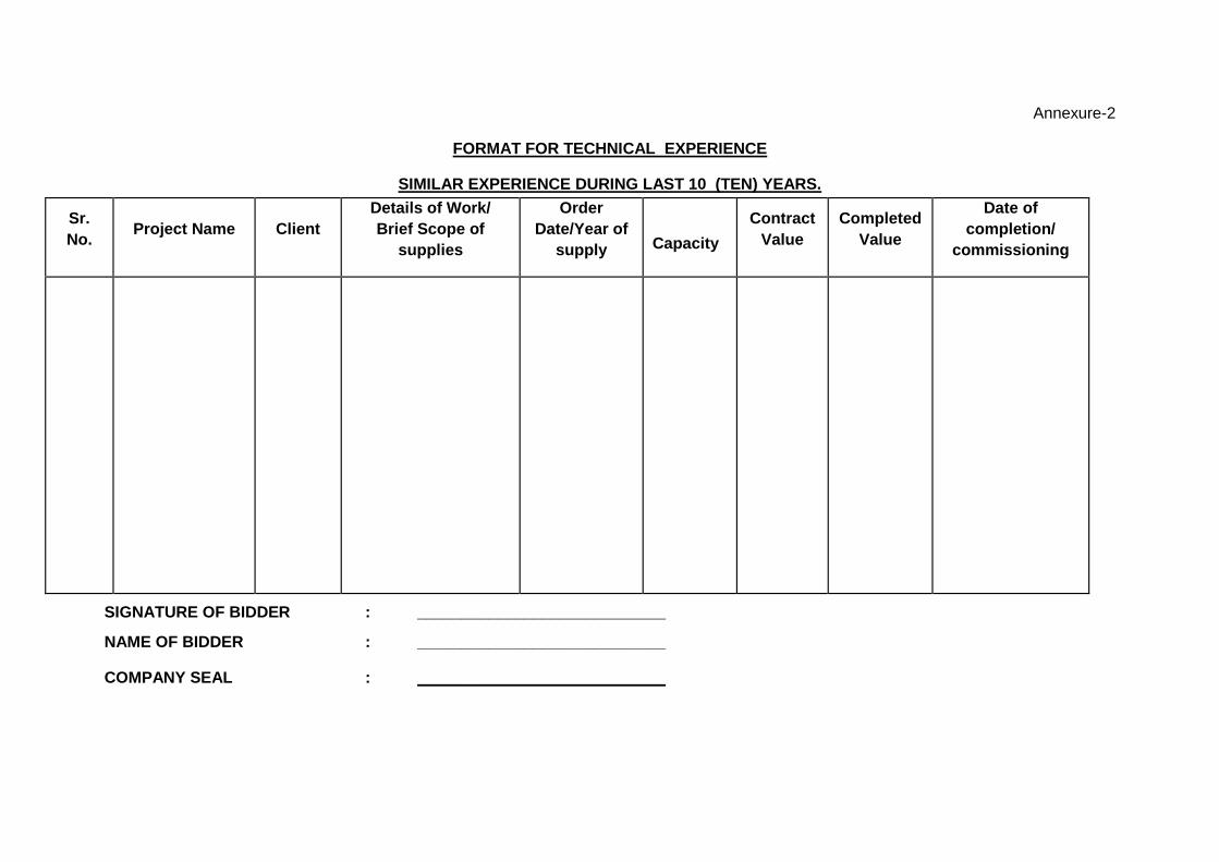
Annexure-2
FORMAT FOR TECHNICAL EXPERIENCE
SIMILAR EXPERIENCE DURING LAST 10 (TEN) YEARS.
Sr.
No. Project Name Client
Details of Work/
Brief Scope of
supplies
Order
Date/Year of
supply
Capacity
Contract
Value
Completed
Value
Date of
completion/
commissioning
SIGNATURE OF BIDDER : ____________________________
NAME OF BIDDER : ____________________________
COMPANY SEAL : ____________________________

Page 1 of 2
PRE TENDER MEET
(ASSAM BIO REFINERY PROJECT LTD.)
A. ANNUAL TURNOVER OF LAST 3 YEARS:
Year Amount (INR)
Year 1: 2017-18
Year 2: 2016-17
Year 3: 2015-16
B. FINANCIAL DATA FOR LATEST AUDITED FINANCIAL YEAR (FY__________):
Description Amount (INR)
Net Worth
Working capital
C. Balance sheet in the name of ___________________________________ D. Holiday list / banned of any PSU / GOVT organization ______________________ ** Bidders are requested to enclose “Balance sheets of all Three years” & “Organisation structure” while submitting this annexure.

Page 2 of 2
1. Net worth Calculation:
Networth means paid up share capital, Share Application Money pending allotment* and reserves# less accumulated losses and deferred expenditure to the extent not written off.
# Reserves to be considered for the purpose of networth shall be all reserves created out of the
profits and securities premium account but shall not include reserves created out of revaluation of
assets, write back of depreciation and amalgamation.
*Share Application Money pending allotment will be considered only in respect of share to be allotted.
Accordingly, the definition of Networth shall be as follows:
Paid up share capital XXXX
Add: Share Application Money pending allotment XXX
Add: Reserves (As defined Above) XXXX
Less: Accumulated Losses XX
Less: Deferred Revenue Expenditure to the extent not written off XX
Networth XXXX
2. Working Capital calculation:
Working Capital shall be Current Assets minus Current Liabilities.
3. TurnoverCalculation:
Turnover shall be calculated including Excise Duty but excluding otherIncomes.