invitation to bid swithgear replacement, pensacola campus
TRANSCRIPT

1
Invitation to Bid
Swithgear Replacement, Pensacola Campus 29-2015/2016
Deliver Sealed Bid and Two Copies to:
Cassie Boatwright, Director of Purchasing and Auxiliary Services Building 7, Room 737
1000 College Blvd. Pensacola, FL 32504
Public bid opening: Pensacola State College will conduct a Public bid opening and evaluations on the date and time listed within the timeline which are held at Pensacola State College Board Room, 1000 College Blvd. Pensacola, FL 32504 Room 736. The College may choose to only open the individual bids and publicly announce who a bid was received from. The actual bid prices submitted will not be a public record until the date of posting or the number of days as defined in FS 119.071. Immediately following the bid opening, the Bid Evaluation Committee will evaluate the bids. This may require additional review by the committee or representative. Timeline
The following timeline is a general guideline for issuance, evaluation, ranking and recommendation for award of this Invitation to Bid. The College reserves the right to change the dates of any events listed. Times listed are local time. DATE EVENT
April 26, 2016 ITB issue date May 24, 2016, 8am Site Visit on location May 26, 2016, 2pm Deadline for questions and requests for clarifications June 7, 2016, 2pm Bids due
The timeline above is a proposed schedule. The College may amend the dates as required. All dates and locations of evaluation committee meetings will be posted to Purchasing’s website: http://www.pensacolastate.edu/business-psc/. Pensacola State College is a political subdivision of the State of Florida and as such is exempt from all Federal and State taxes. Pensacola State College reserves the right to reject any portion or all bids, to resolicit bids or not and to waive informalities as deemed in the best interest of Pensacola State College. The bid shall remain in force for ninety (90) days after the time of opening. ANTI-COLLUSION STATEMENT: The Bidder by signing and submitting a bid has "not" divulged to, discussed or compared his/her bid with any other Bidders and has not colluded with any other Bidders or parties to a bid whatsoever. (NOTE: Including there have been No premiums, rebates or gratuities paid or permitted either with, prior to, or after any delivery or personal contact. Any such violation will result in the cancellation of award of any resulting contract from this bid and the Bidder being debarred for not less than three (3) years of doing business with Pensacola State College.)

2
1.0 OVERVIEW Pensacola State College is soliciting qualified bids from qualified firms to provide equipment and installation as identified within the attachment.
1.01 In order to maintain a fair and impartial competitive process, Pensacola State College shall avoid any oral communication with prospective bidders other than through the purchasing office during the bid process. However, all solicited bidders will be provided a copy of all written questions submitted and Pensacola State College’s responses to them, unless the written inquiry pertained to an administrative or procedural matter. Send all inquiries to the attention of: Cassie Boatwright, Director of Purchasing and Auxiliary Services, Email: [email protected]
From the date of issuance of this ITB, until a proposal is made, Respondent must not make available or discuss its proposal, or any part thereof, with any employee or agent of the College, unless permitted by the Director of Purchasing and Auxiliary services, in writing. Contacting the College’s personnel or members of the College’s District Board of Trustees, either directly or indirectly, regarding this ITB, the selection process or any attempt to further a proposer’s interest in being selected, may result in proposer being disqualified and shall render the award to said proposer voidable by the College. Questions concerning this ITB shall be directed to Cassie Boatwright at [email protected] and to no other person or department at the College. Questions and requests must be in writing and must be received not later than the date and time indicated in the timeline. 1.02 Any addenda issued prior to the opening of the ITB for the purpose of changing the specifications of this request
for proposal or related documents, or clarifying the meaning of the same, shall be binding in the same way as if originally written in the ITB specifications and related documents. Since all addenda are available to proposers at the office of the Pensacola State College Director of Purchasing and Auxiliary Services, it is each bidder’s responsibility to check with the issuing office and immediately secure all addenda before submitting your bid. The Pensacola State College Director of Purchasing and Auxiliary Services emails addenda to all known prospective bidders, but no guarantee can be made that addenda will be received.
1.03 The bidder is assumed to be familiar with all Federal, State of Florida and local laws, ordinances, rules and
regulations that in any manner affect the work. Ignorance on the part of the proposer will in no way relieve you from your contractual responsibility. Any resultant award shall include requirements that the resultant contract shall be governed by the laws of the State of Florida.
1.04 As deemed in the College’s best interest, the College reserves the right to:
1. Reject any or all bids submitted. 2. To resolicit bids or not. 3. To award any portion(s) of this ITB. 4. To waive informalities. 5. To issue to all responsive bidders request for information (RFI’s). 6. To issue requests to negotiate with finalist and solicit best and final offers. 7. To evaluate to determine technical equivalents. 8. To award this ITB on a Lot by Lot basis to the responsive low bidder meeting
specifications. 9. To award on an outright purchase or lease basis.
1.05 A bid bond or deposit, in the amount of five percent (5%) of the base bid will be required to accompany each bid, as guarantee that the successful bidder, will enter into a contract with the Owner, if desired by same. Any deposit must be in the form of a Certified Check, or a Cashier’s Check. The bid bond or deposit will be held as liquidated damages, in the event that the successful bidder refuses to enter into a contract with the Owner. In
3
addition, the successful bidder shall provide a one hundred percent (100%) Performance Bond and one hundred percent (100%) Labor and Material Payment Bond(s), with a surety insurer authorized to do business in the State of Florida as surety, satisfactory to the Owner. 1.06 SCHEDULE: All items shall be completed between 12/16/2016 – 12/31/2016. 1.07 QUALIFICATIONS: Bidders shall furnish documentation of the following:
a. He or She is currently registered with or hold an unexpired License issued by the Florida Construction Industry Licensing Board in accordance with current applicable regulations, Licensing of Construction Industry, Florida Statutes.
b. He or She presently maintains a permanent bona fide place of business practicing this type of work and has had the appropriate experience.
c. He or She has available, or can obtain, adequate equipment and financial resources to undertake and execute the Contract properly and expeditiously, in accordance with present day practices.
d. All subcontractors shall be fully licensed in the State of Florida and shall be bondable. Submit copies of current license and documentation from bonding company showing compliance.
e. He or She shall submit with the Bid the enclosed document entitled “Sworn Statement under Section 287.133(3) (a), Florida Statutes. On Public Crimes”.
The apparent successful bidder shall also, at the request of the College, submit a fully executed “Contractor’s Qualification Statement” AIA Document A305.
1.08 LICENSE: In accordance with Chapter 489.113, Florida Statutes, all individuals or entities engaging in and providing construction services shall be licensed in the State of Florida for that activity. This license requirement includes general and sub-contractors. The successful low bidder shall be required to submit a list of all contractors to be involved in said project with applicable license numbers (see form included in these documents), including a photographic copy of current license certificates. Submittal of proof of license shall be made with, and as a part of signed contract. Prime Contractor shall submit proof of licensure with the Bid Form. Failure to submit required proof of license shall be cause for Owner to reject bid as non-responsive, and award bid to second lowest qualified bidder. 1.09 DISQUALIFICATION OF BIDDER: More than one Bid from an individual, firm, partnership, corporation or association under the same or different names will not be considered. Reasonable grounds for believing that a Bidder is interested in more than one Bid for the same will cause the rejection of all Bids which such Bidder is believed to be interested. Bids will be rejected if there is reason to believe that collusion exists between Bidders. Bids in which the prices are obviously unbalanced may be rejected. 1.10 MODIFICATION OF BID: Bid modifications will be accepted from Bidders if addressed to the Owner at the place where Bids are to be received and if received prior to the opening of the Bids. Modifications may be in written or telegraphic form. Modifications will be acknowledged by the Owner before opening of formal Bids. 1.11 WITHDRAWAL OF BIDS: Bids may be withdrawn by written or telegraphic request received from Bidders prior to the time fixed for opening. Negligence on the part of the Bidder in preparing the Bid confers no right for the withdrawal of the Bid after it has been opened. 1.12 BUILDING PERMIT: A permit may be issued to the Contractor by the Facilities Planning and Construction Department of Pensacola State College. 1.13 SECURITY: The Contractor shall be responsible for maintaining security, and the contractor shall be responsible

4
for replacement or repair of items and/or equipment stolen, lost or damaged while the building security is under the care of the Contractor. The Contractor shall be responsible for having a job superintendent present whenever work is in progress. The Contractor shall not change superintendent without the Owners approval.
2.00 GENERAL Must meet or exceed the specifications listed in Attachment A. 2.01 BASIC DEFINITIONS: Unless otherwise expressly stated, wherever in the Contract Documents the word ‘provide’ is used, it shall mean furnished and installed in place, complete and tested. The terms Architect and Engineer are used interchangeably.
2.02 CORRELATION AND INTENT OF THE CONTRACT DOCUMENTS: If a discrepancy occurs on drawings, in specifications, or between drawings and specifications, the greater quantity or value takes precedence.
2.03 WARRANTY: The warranty herein guarantees the proper operation of all structures, components and systems constructed or installed by the contractor for a period of one year after the date of substantial completion.
If within the guarantee period, repairs or changes are required in connection with the guarantee work, which in the opinion of the Architect is rendered necessary as the result of the use of materials, equipment, or workmanship, which are defective, or inferior, or not in accordance with the terms of the Contract, the Contractor shall, promptly upon receipt of notice from the Owner, and without expense to the Owner, proceed to:
Place in satisfactory condition in every particular all of such guaranteed work, correct all defects therein; and Make good all damages to the structure or site, or equipment or contents thereof which, in the opinion of the Architect are the result of the use of materials, equipment or workmanship which are inferior, defective, or not in accordance with the terms of the Contract, or the equipment and contents or structures or site disturbed in fulfilling any such guarantee.
2.04 INDEMNIFICATION: The Contractor shall, for the sum of one hundred dollars ($100.00) and other good and valuable consideration paid by the Owner and Architect, individually, receipt of which is hereby acknowledged by the Contractor, indemnify and hold harmless the Owner and Architect and their agents and employees from and against all claims, damages, losses and expenses, including attorney’s fees, out of or resulting from the performance of the work provided that such claims, damage, loss or expense: (1) is attributable to bodily injury, sickness, disease or death, or injury to or destruction of tangible property other than the work itself, including the loss of use resulting there-from, and (2) is caused in whole or in part by a negligent act or omission of the Contractor, subcontractor, anyone directly or indirectly employed by any of them or anyone for whose acts any one of them may be liable, regardless of whether or not it is caused in part by a party indemnified hereunder. This obligation shall not be construed to reduce or negate any other right or obligation of indemnity which would otherwise exist as to any party or person described in this invitation to bid.
2.05 SUBCONTRACTORS: The Contractor shall not contract with any person or entity declared ineligible under Federal laws or regulations from participating in federally assisted construction projects or to whom the Owner or the Architect has made reasonable objection.
2.06 CHANGES IN WORK: Maximum percentages of overhead and profit which may be added by the Contractor to actual costs of such changes in the work are specifically set forth as follows:
For all work done by his organization, or subsidiaries of his organizations, including work traditionally considered as subcontractor work, the Contractor may add 15% of his actual costs for combined overhead and profit.

5
For any work performed by a subcontractor or forces under the respective subcontractor including any sub- subcontractors or persons not in the direct employ of the subcontractor, a total of 15% of the cost of the change, with 10% to be assigned to the subcontractor and any forces under him and the General Contractor may add 5% of the cost above subcontractor's cost for his overhead and profit.
The above percentages shall be considered reasonable allowance for overhead and profit due to the contractor. The Contractor shall submit receipts or other evidence showing his costs and his right to the payment claims. All changes in work shall be provided with a detailed cost breakdown indicating material and labor units for all work to be performed. In addition, the cost breakdown shall contain all current tax and labor burden. The allowable amount for the material tax shall be 7.25% and for labor burden shall be 30%.
2.07 INSURANCE AND BONDS: The Contractor shall not commence any work in connection with this agreement until he has obtained all of the following types of insurance with the Owner as additional named insured and such insurance has been approved by the Owner, nor shall the Contractor allow any subcontractor to commence work on his subcontract until all similar insurance required of the subcontractor to commence work on his subcontract has been obtained and approved.
All insurance policies shall be with insurers qualified and doing business in Florida. THE CONTRACTOR SHALL PROCURE AND MAINTAIN FOR THE LIFE OF THIS CONTRACT: 1. Workers Compensation and Employers’ Liability as follows:
a. WC Statutory Limits per FS 440 b. E.L. - Each Accident $500,000 c. E.L. Disease – Each Employee $500,000 d. E.L. Disease – Policy Limit $500,000
2. Comprehensive General Liability with minimum limits as follows: a. Each Occurrence - $ 1,000,000 b. Damage to Rented Premises (Each occurrence)- $100,000 c. Medical Expense (Any one person) $5,000 d. Personal Advertising Injury - $1,000,000 e. General Aggregate - $2,000,000 f. Products-Completed Aggregate - $2,000,000 g. General Aggregate applies to Per Project
3. Automobile Liability providing coverage on any auto to include all owned, hired and non-owned vehicle with following minimum limits:
a. Combined Single Limit (Each Accident) - $1,000,000 OR b. Bodily Injury per person - $500,000, Bodily Injury per Accident - $1,000,000, Property Damage per
Accident - $500,000 4. Excess/Umbrella Liability on Occurrence Form with following limit:
a. $1,000,000 each occurrence b. $2,000,000 aggregate c. Retention /Deductible - $5,000
The Contractor liability policy shall provide "XCU" (Explosion, Collapse, Underground Damage) coverage for those
classifications in which they are included.
Broad Form Property Damage shall be required on Contractor's public liability so that completed operations coverage extends to work performed by the Contractor.

6
Builders Risk Insurance: Contractor shall purchase and maintain in effect a completed value builder's risk policy issued by an admitted carrier in an amount equal to the full completed value of the project. Such insurance shall be issued on an all risk form. The Contractor shall be responsible for any deductible amounts.
The Contractor shall furnish a Performance Bond in an amount equal to one hundred percent (100%) of the
Contract Sum as security for the faithful performance of this Contract and also a Labor and Material Payment Bond in an amount not less than one hundred percent (100%) of the Contract Sum or in a penal sum not less than that prescribed by State, Territorial or local law, as security for the payment of persons performing labor on the Project under this Contract and furnishing materials in connection with this Contract. The Performance Bond and the Labor and Material Payment Bond may be in one or in separate instruments in accordance with local law and shall be delivered to the Owner not later than the date of execution of the Contract. The premium for the required bonds shall be paid by the Contractor. "These bonds shall be executed on behalf of the Contractor in the same manner and by the same person who executed the agreement.
To be acceptable as surety on Performance and Payment Bonds, a surety company shall comply with the following
provisions:
The Surety Company must be admitted to do business in the State of Florida. The surety Company shall have been in business and have a record of successful continuous operations for at least five years. The Surety Company shall have at least the following minimum ratings:
Contract Amount Policy Holders Required Rating 0 - 100,000 B CLASS VII 100,000 - 500,000 A CLASS VIII 500,000 - 750,000 A CLASS IX 750,000 - 1,000,000 A CLASS X 1,000,000 - 1,250,000 A CLASS XI 1,250,000 - 1,500,000 A CLASS XI 1,500,000 - 2,000,000 A CLASS XII 2,000,000 - 2,500,000 A CLASS XII
*From Best's key rating guide.
Best's Policy Holder's Rating of "A" and "B" (which signifies A--Excellent, and B-Good, based upon good underwriting, economic management, adequate reserves for undisclosed liabilities, net resources for unusual stock and sound investment) or an equivalent rating from the Insurance Commissioner, if not rated by Best's. Neither the Surety Company nor any reinsurer shall expose itself to any loss on any one risk in an amount exceeding ten (10%) percent of its surplus to policyholders.
In the case of a surety insurance company, there shall be deducted in addition to the deduction for reinsurance, the amount assumed by any co-surety, the value of any security deposited, pledged or held subject to the content of the Surety and for the protection of the Surety."
Furnish in triplicate a Performance Bond and a Payment Bond, each in the amount of 100% of the Contract Sum, written by a surety licensed to do business in the state where the Project is located. The prescribed form of the Performance Bond and Payment Bond is AlA Document A313.
2.08 LIQUIDATED DAMAGES: If the Contractor fails to complete the working within the time specified, the Contractor shall pay liquidated damages to the College in the amount of $XXXX for each calendar day until the work is completed or accepted.

7
3.00 SPECIAL CONDITIONS 3.01 Florida sales tax exemption no: 85-8012557294C-2. 3.02 Pensacola state college reserves the right to reject any or all ITBs/proposals received, to resolicit or not and to
waive informalities as deemed in the best interests of the College. 3.04 Any entity or affiliate who has been placed on the discriminatory vendor list may not submit a ITB on a contract
to provide goods or services to a public entity, may not submit a ITB on a contract with a public entity for the construction or repair of a public building or public work, may not submit ITBs on leases of real property to a public entity, may not award or perform work as a contractor, supplier, subcontractor, or consultant under contract with any public entity, and may not transact business with any public entity. All invitations to ITB, as defined by 287.012(11)FS, request for proposals, as defined by 287.012(15)FS, and any written contract document of the state shall contain a statement informing entities of the discrimination provisions.
3.05 Pensacola State College reserves the right to award an individual lot or a combination of lots; reject any or all lots,
whatever seems in the best interest of the College. 3.06 The specifications listed are meant to demonstrate the work parameters required, and the functional limits listed
are to be considered minimal unless changed by addendum to the bid. Bid evaluation will be made strictly from the minimal specification. Each particular specification which the equivalent offered which does not meet must be identified and submitted along with the detailed specification sheet of the equivalent offered.
3.07 The successful bidder shall fully guarantee all items furnished against defect in materials and/or workmanship for
a period of 365 days from date of final acceptance by Pensacola State College. Should any such defect, except for normal wear and tear, appear during the warranty period, the successful bidder shall commence repair or replace same at no cost to Pensacola State College within 72 hours after notice.
3.08 Any "notice of protest" involving the specifications, the terms and conditions or any other aspect of this invitation
to bid (ITB), request for proposal (ITB) or request for qualification (RFQ) must be filed in writing within 72 hours after posting. Formal written protest must be filed within 10 days after the date of the notice of protest is filed. (Saturdays, Sundays and legal holidays shall be excluded in these computations.) The formal written protest shall state with particularity the facts and law upon which the protest is based. Failure to file a notice of protest or failure to file a formal written protest within the time prescribed in section 120.57(3), Florida Statutes shall constitute a waiver of proceedings under chapter 120, Florida Statutes.
3.09 Bid tabulations with recommended awards will be posted on the purchasing web page
http://pensacolastate.edu/purchasing/current_solicitations.asp Unless changed by addendum, and will remain posted for a period of 72 hours (not including Saturdays, Sundays and legal holidays). Any notice of protest of award or recommendation of award shall be filed in writing to the Director of Purchasing, within 72 hours after the posting of the ITB/ITB/RFQ bid tabulation. "Failure to file a protest within the time prescribed in section 120.57 (3), Florida statutes shall constitute a waiver of proceedings under chapter 120, Florida Statutes." A formal written protest must be filed within 10 days (excluding Saturdays, Sundays, and legal holidays) after the date the notice of protest was filed. The formal written protest shall state with particularity the facts and law upon which the protest is based upon. Failure to file a formal written protest within the time prescribed shall constitute a waiver of proceedings under chapter 120.57(3) Florida Statutes. Inspection or examination of sealed bids or proposals are available for inspection during normal working hours by appointment, upon notice of a decision or intended decision, or 10 days after invitation to bid or proposal public opening, whichever is earlier.
3.11 SPECIAL POLICY AND PROCEDURES: Contractor and subcontractor personnel are not permitted to use the

8
campus facilities. Smoking is not permitted in any campus facility. Profane language or improper behavior will result in immediate termination from the construction site.
The Contractor shall erect temporary barricades and fencing as required to keep the unauthorized out of the construction area, and provide signs that read. “This area is a designated construction site; anyone who trespasses on this property commits a felony per Florida Statute 810.09(2d).

9
BID FORM
Total Lump Sum Cost as specified $ ____________ Payment Terms: Net 30 days or prompt payment discount of ____%, _____ Days offered by Proposer.
All fi
Firm
__________________________________ ______________________________________ _______________ Authorized Agent Name Signature Date
Firms certify by their signature they have read and understand the conditions and specifications of this Invitation to Bid and they have the authority, capacity, and capability to perform all conditions and specifications of this Invitation to Bid.
10
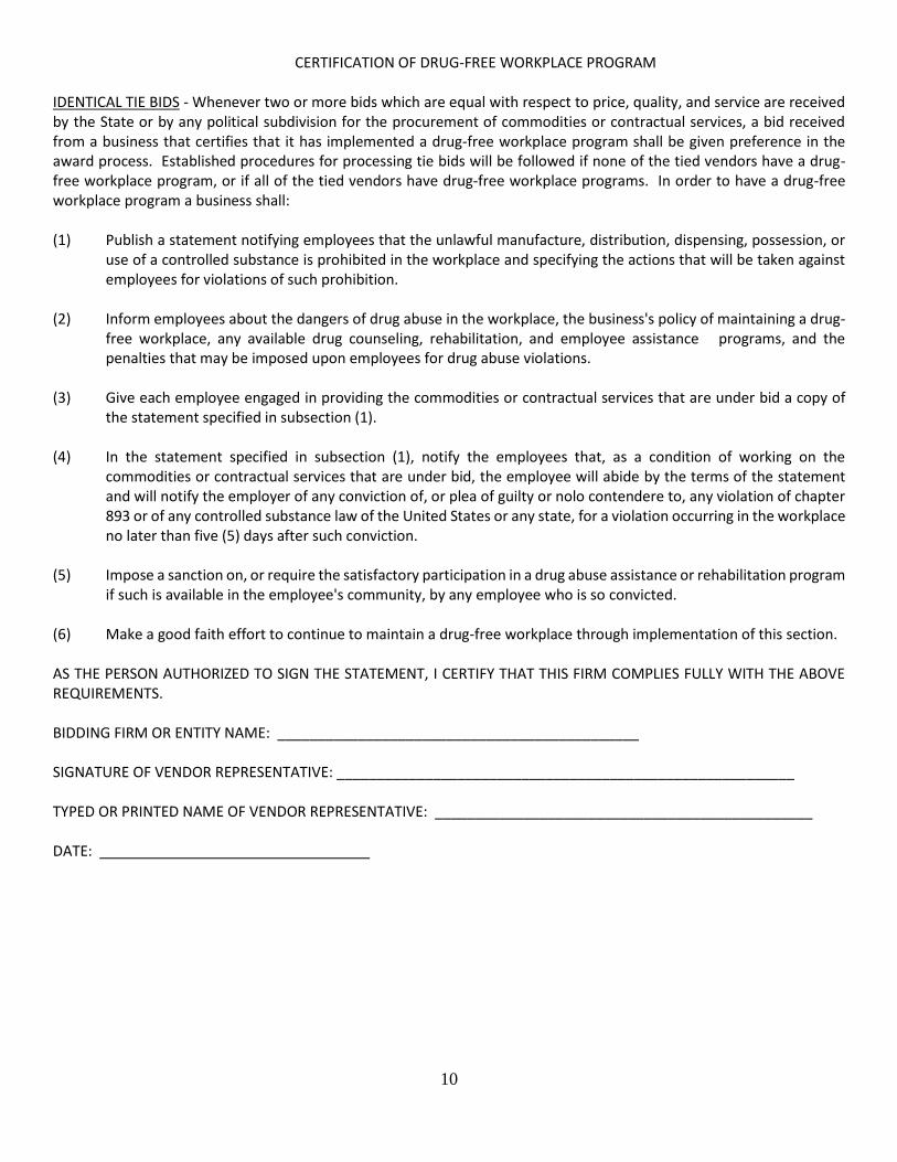
CERTIFICATION OF DRUG-FREE WORKPLACE PROGRAM IDENTICAL TIE BIDS - Whenever two or more bids which are equal with respect to price, quality, and service are received by the State or by any political subdivision for the procurement of commodities or contractual services, a bid received from a business that certifies that it has implemented a drug-free workplace program shall be given preference in the award process. Established procedures for processing tie bids will be followed if none of the tied vendors have a drug-free workplace program, or if all of the tied vendors have drug-free workplace programs. In order to have a drug-free workplace program a business shall: (1) Publish a statement notifying employees that the unlawful manufacture, distribution, dispensing, possession, or
use of a controlled substance is prohibited in the workplace and specifying the actions that will be taken against employees for violations of such prohibition.
(2) Inform employees about the dangers of drug abuse in the workplace, the business's policy of maintaining a drug-
free workplace, any available drug counseling, rehabilitation, and employee assistance programs, and the penalties that may be imposed upon employees for drug abuse violations.
(3) Give each employee engaged in providing the commodities or contractual services that are under bid a copy of
the statement specified in subsection (1). (4) In the statement specified in subsection (1), notify the employees that, as a condition of working on the
commodities or contractual services that are under bid, the employee will abide by the terms of the statement and will notify the employer of any conviction of, or plea of guilty or nolo contendere to, any violation of chapter 893 or of any controlled substance law of the United States or any state, for a violation occurring in the workplace no later than five (5) days after such conviction.
(5) Impose a sanction on, or require the satisfactory participation in a drug abuse assistance or rehabilitation program
if such is available in the employee's community, by any employee who is so convicted. (6) Make a good faith effort to continue to maintain a drug-free workplace through implementation of this section. AS THE PERSON AUTHORIZED TO SIGN THE STATEMENT, I CERTIFY THAT THIS FIRM COMPLIES FULLY WITH THE ABOVE REQUIREMENTS. BIDDING FIRM OR ENTITY NAME: _____________________________________________ SIGNATURE OF VENDOR REPRESENTATIVE: _________________________________________________________ TYPED OR PRINTED NAME OF VENDOR REPRESENTATIVE: _______________________________________________ DATE:

11
MINORITY BUSINESS ENTERPRISE/WOMAN BUSINESS ENTERPRISE CERTIFICATE
I HEREBY DECLARE AND AFFIRM that I am the ____________________________ (Title) representative of the firm of _____________________________________________ (Company Name) minority business enterprise (MBE/WBE)___________________ (Minority Type) as defined by Pensacola State College in the specifications for ______________________________________________________________(ITB Name & Number) that I will provide information requested by PENSACOLA STATE COLLEGE to document this fact. The foregoing statements are true and correct and include all material necessary to identify and explain the operations of ____________________________________ (Company Name) as well as the ownership thereof. Further, the undersigned does agree to provide PENSACOLA STATE COLLEGE current, complete and accurate information regarding actual work performed on the project, the payment therefor and any proposed changes in any of the arrangements hereinabove stated and to permit and audit an examination of the books, records and files of the above named company by authorized representative of PENSACOLA STATE COLLEGE. It is recognized and acknowledged that the statements herein are being given under oath and material misrepresentation will be grounds for terminating any contract which may be awarded in reliance hereon. Termination is understood to forfeiture of payment for all work not performed at time of notification. I DO SOLEMNLY DECLARE OR AFFIRM UNDER THE PENALTIES OF PERJURY THAT THE CONTENTS OF THE FOREGOING DOCUMENTS ARE TRUE AND CORRECT, AND THAT I AM AUTHORIZED, ON BEHALF OF THE ABOVE FIRM, TO MAKE THIS AFFIDAVIT. ___________________________________ Signature of Company's Authorized Representative State of ________ __________County of ____________ ____________City of ___________________________ On this ________________ day of _____________________, 20_____, before me, in the foregoing affidavit and acknowledged that he (she) executed the same in the capacity therein stated and for the purpose therein contained. In witness thereof, I hereunto set my hand and official seal. Signed: ___________________________ (SEAL) Notary Public My commission Expires: Minority Type: # M1 Black American Man; M2 Hispanic American; M3 Asian American; M4 Native American (Eskimo & Aleutian); M5 Native Hawaiian; M6 Small Business; M7 Disabled; M8 American Woman; M9 Black American Woman; and NM Not Minority. (Must have greater than 51% minority ownership). "Minority/Woman Business Enterprises that file false misrepresentation of their MBE/WBE status shall be found guilty of a felony of the second degree and be debarred from bidding no less than 36 months pursuant to 287.094 Florida Statute".
Pensacola State College does not discriminate on the basis of race, ethnicity, national origin, gender, age, religion, marital status, disability, sexual orientation and genetic information in its educational programs and activities. The following person has been designated to handle inquiries regarding nondiscrimination policies: Dr. Gael Frazer, Assoc. Vice President, Institutional Diversity at (850)484-1759, Pensacola State College, 1000 College Blvd. Pensacola, Florida 32504
12
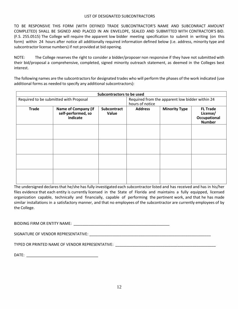
LIST OF DESIGNATED SUBCONTRACTORS
TO BE RESPONSIVE THIS FORM (WITH DEFINED TRADE SUBCONTRACTOR’S NAME AND SUBCONRACT AMOUNT COMPLETED) SHALL BE SIGNED AND PLACED IN AN ENVELOPE, SEALED AND SUBMITTED WITH CONTRACTOR'S BID. (F.S. 255.0515) The College will require the apparent low bidder meeting specification to submit in writing (on this form) within 24 hours after notice all additionally required information defined below (i.e. address, minority type and subcontractor license numbers) if not provided at bid opening. NOTE: The College reserves the right to consider a bidder/proposer non responsive if they have not submitted with their bid/proposal a comprehensive, completed, signed minority outreach statement, as deemed in the Colleges best interest. The following names are the subcontractors for designated trades who will perform the phases of the work indicated (use additional forms as needed to specify any additional subcontractors):
Subcontractors to be used Required to be submitted with Proposal Required from the apparent low bidder within 24
hours of notice Trade Name of Company (if
self-performed, so indicate
Subcontract Value
Address Minority Type FL Trade License/
Occupational Number
The undersigned declares that he/she has fully investigated each subcontractor listed and has received and has in his/her files evidence that each entity is currently licensed in the State of Florida and maintains a fully equipped, licensed organization capable, technically and financially, capable of performing the pertinent work, and that he has made similar installations in a satisfactory manner, and that no employees of the subcontractor are currently employees of by the College. BIDDING FIRM OR ENTITY NAME: _____________________________________________ SIGNATURE OF VENDOR REPRESENTATIVE: _________________________________________________________ TYPED OR PRINTED NAME OF VENDOR REPRESENTATIVE: _______________________________________________ DATE:

13
PUBLIC ENTITY CRIMES
Any person submitting a Request for Proposal in response to this invitation must execute the enclosed for PUR 7068, SWORN STATEMENT UNDER PARAGRAPH 287.133(3)(A), FLORIDA STATUTES, ON PUBLIC ENTITY CRIMES, including proper check(s), in the space(s) provided, and enclose it with the said statement. However, if you have provided the completed form to the submittal address listed in this invitation and it was received on or after January 1, 2009, another completed form is not required for the remaining calendar year.
THIS FORM MUST BE SIGNED IN THE PRESENCE OF A NOTARY PUBLIC OR OTHER OFFICIAL AUTHORIZED TO ADMINISTER OATHS.
This sworn statement is submitted to:
(print name of the public entity)
By (Print name of entity submitting sworn statement)
Whose business address is
And (if applicable) its Federal Employer Identification No. (FEIN) is:
(If the entity has no FEIN, include the Social Security Number of the individual signing this sworn statement:
I understand that a "public entity crime" as defined in Paragraph 287.133(1)(g), Florida Statutes, means a violation of any state or federal law by a person with respect to and directly related to the transaction of business with any public entity or with an agency or political subdivision of any other state or of the United States, including, but not limited to, any proposal or contract for goods or services to be provided to any public entity or an agency or political subdivision of any other state or of the United States and involving antitrust, fraud, theft, bribery, collusion, racketeering, conspiracy, or material misrepresentation.
I understand that "convicted" or "conviction" as defined in Paragraph 287.133(1)(b), Florida Statutes, means a finding of guilt or a conviction of a public entity crime, with or without an adjudication of guilt, in any federal or state trial court of record relating to charges brought by indictment or information after July 1, 1989, as a result of a jury verdict, non-jury trial, or entry of a plea of guilty or nolo contendere.
I understand that an "affiliate" as defined in Paragraph 287.133(1)(a), Florida Statutes, means:
A predecessor or successor of a person convicted of a public entity crime: or
An entity under the control of any natural person who is active in the management of the entity and who has been convicted of a public entity crime. The term "affiliate" includes those officers, directors, executives, partners, shareholders, employees, members, and agents who are active in the management of an affiliate. The ownership by one person of shares constituting a controlling interest in another person, or a pooling of equipment or income among persons when not for fair market value under an arm's length agreement, shall be a prima facie case that one person controls another person. A person who knowingly enters into a joint venture with a person who has been convicted of a public entity crime in Florida during the preceding 36 months shall be considered an affiliate.
I understand that a "person" as defined in Paragraph 287.133(1) (e), Florida Statutes, means any natural person or entity organized under the laws of any state or of the United States with the legal power to enter into a binding contract and which proposals or applies to proposal on contracts for the provision of goods or services let by a public entity, or which otherwise transacts or applies to transact business with a public entity. The term "person" includes those officers, directors, executives, partners, shareholders, employees, members, and agents who are active in management of an entity.
Based on information and belief, the statement which I have marked below is true in relation to the entity submitting this sworn statement (indicate which statement applies).
______Neither the entity submitting this sworn statement, nor any officers, directors, executives, partners, shareholders, employees, members, or agents who are active in the management of the entity, nor any affiliate of the entity have been charged with and convicted of a public entity crime subsequent to July 1, 1989.
______The entity submitting this sworn statement, or one or more of the officers, directors, executive, partners, shareholders, employees, members, or agents who are active in management of the entity or an affiliate of the entity has been charged with and convicted of a public entity crime subsequent to July 1, 1989.
______The entity submitting this sworn statement, or one or more of its officers, directors, executives, partners, shareholders, employees, members, or agents who are active in the management of the entity or an affiliate of the entity has been charged with and convicted of a public entity crime subsequent to July 1, 1989. However, there has been a subsequent proceeding before a Hearing Officer of the State of Florida, Division of Administrative Hearings and the Final Order entered by the Hearing Officer determined that it was not in the public interest to place the entity submitting this sworn statement on the convicted vendor list (attach a copy of the final order).
I UNDERSTAND THAT THE SUBMISSION OF THIS FORM TO THE CONTRACTING OFFICER FOR THE PUBLIC ENTITY IDENTIFIED IN PARAGRAPH 1 (ONE) ABOVE IS FOR THAT PUBLIC ENTITY ONLY AND, THAT THIS FORM IS VALID THROUGH DECEMBER 31 OF THE CALENDAR YEAR IN WHICH IT IS FILED.

14
I ALSO UNDERSTAND THAT I AM REQUIRED TO INFORM THE PUBLIC ENTITY PRIOR TO ENTERING INTO A CONTRACT IN EXCESS OF THE THRESHOLD AMOUNT PROVIDED IN SECTION 287.017, FLORIDA STATUTES FOR CATEGORY TWO OF ANY CHANGE IN THE INFORMATION CONTAINED IN THIS FORM.
Sworn to and subscribed before me this day of 20
Personally known
OR Produced identification Notary Public - State of
. My commission expires (Type of identification)
(Printed, typed and/or stamped commissioned name of Notary Public)
A person or affiliate who has been placed on the convicted Firm list following a conviction for a public entity crime may not submit a proposal on a contract to provide any goods or services to a public entity, may not submit a proposal on a contract with a public entity for the construction or repair of a public building or public work, may not submit proposals on leases of real property to a public entity, may not be awarded or perform work as a Firm, supplier, Sub-Firm, or consultant under a contract with any public entity, and may not transact business with any public entity in excess of the threshold amount provided in Section 287.017, for CATEGORY TWO for a period of thirty-six (36) months from the date of being placed on the convicted Firm list.

Purchasing & Auxiliary Services [email protected]
Phone: (850) 484-1794 Fax: (850) 484-1839
Tax Reporting Name Name shown on income tax return
Company Name If applicable, DBA name for checks
Federal Tax Identification Number ______ Employer Identification Number OR Social Security Number
Type of Business Corporation Sole Proprietor Partnership LLC ________(classification)
Order form Information (Information for Obtaining Quotes/Purchase Order Submission)
_________________________ Street/PO Box City State/Zip ____ __________________________________ Contact Person Name/Title Phone Fax ____________________________________________________ ______________________________________________________________ Email Address Website
Vendor Registration
Payment Address Same as Above
________ _ Street/PO Box City State Zip ________ Contact Person Name Title ______________________________________________________________ ______________________________________________________ Email Address Website
Minority Business Status Check all that apply to your organization
African American (person having origins in any of the black racial groups of the African Diaspora, regardless of cultural origin)
Hispanic American (person of Spanish or Portuguese culture with origins in Spain, Portugal, Mexico, South America, Central America, or the Caribbean,
regardless of race)
Asian American (person having origins in any of the original peoples of the Far East, Southeast Asia, the Indian Subcontinent, or the Pacific Islands,
including the Hawaiian Islands before 1778)
Native American (person who has origins in any of the Indian Tribes of North America before 1835)
American Woman
Ability to Conduct Business
Is your organization legally able to conduct business with public entities in the State of Florida, pursuant to Florida Statute 287.133,
and with the Federal Government as per epls.gov? No Yes
At the present time, or at any time in the last twelve months, has any owner, officer, stockholder, employee or other person with an
interest either directly or indirectly with your company been employed by Pensacola State College? No Yes
I certify that the information supplied herein is correct to the best of my knowledge. I further certify that in doing business with Pensacola State College my firm is in compliance with Chapter 112.313, Florida Statutes, relating to conflict of interest (www.flsenate.gov/Statutes/). I agree to the Purchase Order Terms and Conditions of Pensacola State College. _______ _ _____________ Authorized Signature Name and Title Date

BUILDING 50
PENSACOLA STATE COLLEGEREPLACE POWER SWITCHBOARDS
MAIN CAMPUS
SITE LOCATION MAP
292
297
90
10
742
298A
298
98
173
297
292
293
292
98
30
297
727
173
30
296A
298
173
10A
399
292
295A
295
30
295
453
443
292
30
98
10A
90
10
297
SAUFLEY
NAS
FIELD
296
297
8
10
99
184
297A
186
97
297A
184
95A
10A
90
453
296
95A
8A
110
29
95
290
10
289
291
296
742
10
8
290
186
297
749
749
90
10
399
399
399
99
99A
97A
97
97A
99
99A
99
97
164
4
99
97
196
95A
29
95
196
184
182
97
182
95
164
9595
29
4
168
4A
4
4A
4A
95
29
4
PENSACOLA, FLORIDA
ELECTRICAL DRAWING INDEXE100 ELECTRICAL SHEET INDEX & LOCATON MAP
E200 LEGEND, NOTES AND DETAILS
E201 PSC MAIN CAMPUS MAP
E300 SINGLE LINE RISERS
E301 PANEL SCHEDULES
E400 BUILDING 50 EXISTING ELECTRICAL & DEMOLITON
E500 BUILDING 50 NEW WORK & ELECTRICAL DETAILS
E100
ELECTRICALSHEET INDEX
AND LOCATIONMAP
DESIGNED BY:DRAWN BY:
CHECKED BY:
JOB NUMBER:DATE:
SDJTAATAA
02/12/161548
REVISION:DATE: DESCRIPTION:
SEAL:
PROP
RIET
ARY
RIGH
TS C
LAUS
E: IN
FORM
ATIO
N AN
D DA
TA C
ONTA
INED
ON
THIS
DRA
WIN
G IS
CON
FIDE
NTIA
L AND
SHA
LL N
OT B
E US
ED W
ITHO
UT P
RIOR
WRI
TTEN
PER
MISS
ION
BY A
NY E
NTIT
Y NO
T HA
VING
A C
ONTR
ACTU
AL R
ELAT
IONS
HIP
WIT
H TH
E EN
GINE
ER. T
HIS
LEGE
ND S
HALL
BE
MARK
ED O
N AN
Y RE
PROD
UCTI
ONS
HERE
OF IN
WHO
LE O
R IN
PAR
T: H
UMBE
R-GA
RICK
CON
SULT
ING
ENGI
NEER
S ©
COP
YRIG
HT 20
15
142 Elgin Parkway SEFort Walton BeachFlorida, 32548
T: 850.243.6723F: 850.664.5420
FL. Authorization No.00006680Christopher A. Garick; FL. P.E. No.53924
Philip M. Humber; FL. P.E. No.13870
Thomas A. Alexander; FL. P.E. No.73172
Daniel J. White; FL. P.E. No.73790
PEN
SAC
OLA
ST
AT
E C
OLL
EGE
SWIT
CH
BO
AR
D B
LDG
50
03/02
/2016
2:10
PM
- SJO
NES
PEN
SAC
OLA
, FLO
RID
AM
AIN
CA
MPU
S

E L E C T R I C A L L I N E L E G E N D
TYPICAL SERVICE EQUIPMENT FAULT CURRENT LABEL DETAIL
MAXIMUM AVAILABLE FAULT CURRENT
/ / DATE OF CALCULATION
SYMMETRICAL RMS AMPERES
EQUIPMENT NAME
DISCONNECT SWITCHDESCRIPTION NOMENCLATURE
ABBREVIATIONS
G E N E R A L N O T E S
D E M O L I T I O N N O T E S
TYPICAL ARC FLASH HAZARD LABEL DETAIL
Arc Flash and Shock Risks Appropriate PPE
Required
WARNING
ARC FLASH RISK PROTECTION MINIMUM PPE
SHOCK PROTECTION
Arc Flash Boundary 19 in
Incident Energy: 1.3 cal/cm^2
Shock Risk When 480 VAC
Cover is Removed
Limited Approach: 42 in
Restricted Approach: 12 in
4 cal/sq cm, FR shirt (long-sleeve) plus FR
pants (long), or FR coverall, rainwear as
needed.
Hardhat + Safety Glasses or Goggles + Ear
Canal Inserts
Glove Class 00
Leather work shoes
Bus ID:
Prot Device ID:
Calculated Fault Current:
Date of Analysis:
Warning: Changes in equipment settings or system configuration may invalidate the calculated results.
TYPICAL GENERATOR CONNECTION BOX GROUNDING LABEL
FOR CONNECTION OF A
NONSEPARATELY DETRIVED
(FLOATING NEUTRAL) SYSTEM ONLY
E200
LEGEND, NOTESAND DETAILS
DESIGNED BY:DRAWN BY:
CHECKED BY:
JOB NUMBER:DATE:
SDJTAATAA
02/12/161548
REVISION:DATE: DESCRIPTION:
SEAL:
PROP
RIET
ARY
RIGH
TS C
LAUS
E: IN
FORM
ATIO
N AN
D DA
TA C
ONTA
INED
ON
THIS
DRA
WIN
G IS
CON
FIDE
NTIA
L AND
SHA
LL N
OT B
E US
ED W
ITHO
UT P
RIOR
WRI
TTEN
PER
MISS
ION
BY A
NY E
NTIT
Y NO
T HA
VING
A C
ONTR
ACTU
AL R
ELAT
IONS
HIP
WIT
H TH
E EN
GINE
ER. T
HIS
LEGE
ND S
HALL
BE
MARK
ED O
N AN
Y RE
PROD
UCTI
ONS
HERE
OF IN
WHO
LE O
R IN
PAR
T: H
UMBE
R-GA
RICK
CON
SULT
ING
ENGI
NEER
S ©
COP
YRIG
HT 20
15
142 Elgin Parkway SEFort Walton BeachFlorida, 32548
T: 850.243.6723F: 850.664.5420
FL. Authorization No.00006680Christopher A. Garick; FL. P.E. No.53924
Philip M. Humber; FL. P.E. No.13870
Thomas A. Alexander; FL. P.E. No.73172
Daniel J. White; FL. P.E. No.73790
PEN
SAC
OLA
ST
AT
E C
OLL
EGE
SWIT
CH
BO
AR
D B
LDG
50
03/02
/2016
2:10
PM
- SJO
NES
PEN
SAC
OLA
, FLO
RID
AM
AIN
CA
MPU
S

PSC MAIN CAMPUS MAP
AREA OF WORK
E201
PSC MAINCAMPUS MAP
DESIGNED BY:DRAWN BY:
CHECKED BY:
JOB NUMBER:DATE:
SDJTAATAA
02/12/161548
REVISION:DATE: DESCRIPTION:
SEAL:
PROP
RIET
ARY
RIGH
TS C
LAUS
E: IN
FORM
ATIO
N AN
D DA
TA C
ONTA
INED
ON
THIS
DRA
WIN
G IS
CON
FIDE
NTIA
L AND
SHA
LL N
OT B
E US
ED W
ITHO
UT P
RIOR
WRI
TTEN
PER
MISS
ION
BY A
NY E
NTIT
Y NO
T HA
VING
A C
ONTR
ACTU
AL R
ELAT
IONS
HIP
WIT
H TH
E EN
GINE
ER. T
HIS
LEGE
ND S
HALL
BE
MARK
ED O
N AN
Y RE
PROD
UCTI
ONS
HERE
OF IN
WHO
LE O
R IN
PAR
T: H
UMBE
R-GA
RICK
CON
SULT
ING
ENGI
NEER
S ©
COP
YRIG
HT 20
15
142 Elgin Parkway SEFort Walton BeachFlorida, 32548
T: 850.243.6723F: 850.664.5420
FL. Authorization No.00006680Christopher A. Garick; FL. P.E. No.53924
Philip M. Humber; FL. P.E. No.13870
Thomas A. Alexander; FL. P.E. No.73172
Daniel J. White; FL. P.E. No.73790
PEN
SAC
OLA
ST
AT
E C
OLL
EGE
SWIT
CH
BO
AR
D B
LDG
50
03/02
/2016
2:10
PM
- SJO
NES
PEN
SAC
OLA
, FLO
RID
AM
AIN
CA
MPU
S
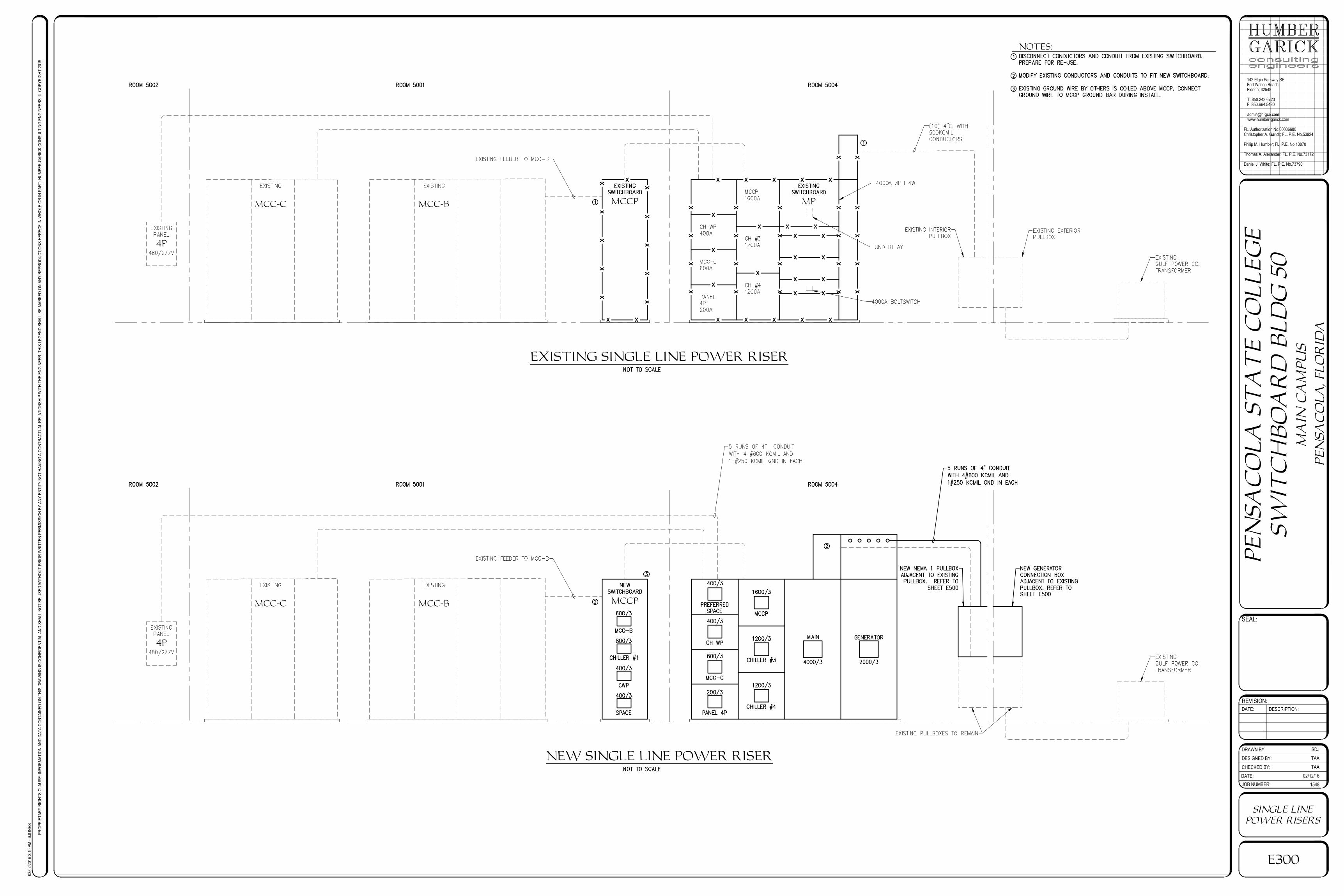
EXISTING SINGLE LINE POWER RISER
MPMCC-BMCC-C
4P
MCCP
NEW SINGLE LINE POWER RISER
MCC-BMCC-C
4P
MCCP
NOTES:
E300
SINGLE LINEPOWER RISERS
DESIGNED BY:DRAWN BY:
CHECKED BY:
JOB NUMBER:DATE:
SDJTAATAA
02/12/161548
REVISION:DATE: DESCRIPTION:
SEAL:
PROP
RIET
ARY
RIGH
TS C
LAUS
E: IN
FORM
ATIO
N AN
D DA
TA C
ONTA
INED
ON
THIS
DRA
WIN
G IS
CON
FIDE
NTIA
L AND
SHA
LL N
OT B
E US
ED W
ITHO
UT P
RIOR
WRI
TTEN
PER
MISS
ION
BY A
NY E
NTIT
Y NO
T HA
VING
A C
ONTR
ACTU
AL R
ELAT
IONS
HIP
WIT
H TH
E EN
GINE
ER. T
HIS
LEGE
ND S
HALL
BE
MARK
ED O
N AN
Y RE
PROD
UCTI
ONS
HERE
OF IN
WHO
LE O
R IN
PAR
T: H
UMBE
R-GA
RICK
CON
SULT
ING
ENGI
NEER
S ©
COP
YRIG
HT 20
15
142 Elgin Parkway SEFort Walton BeachFlorida, 32548
T: 850.243.6723F: 850.664.5420
FL. Authorization No.00006680Christopher A. Garick; FL. P.E. No.53924
Philip M. Humber; FL. P.E. No.13870
Thomas A. Alexander; FL. P.E. No.73172
Daniel J. White; FL. P.E. No.73790
PEN
SAC
OLA
ST
AT
E C
OLL
EGE
SWIT
CH
BO
AR
D B
LDG
50
03/02
/2016
2:10
PM
- SJO
NES
PEN
SAC
OLA
, FLO
RID
AM
AIN
CA
MPU
S

E301
PANELSCHEDULES
DESIGNED BY:DRAWN BY:
CHECKED BY:
JOB NUMBER:DATE:
SDJTAATAA
02/12/161548
REVISION:DATE: DESCRIPTION:
SEAL:
PROP
RIET
ARY
RIGH
TS C
LAUS
E: IN
FORM
ATIO
N AN
D DA
TA C
ONTA
INED
ON
THIS
DRA
WIN
G IS
CON
FIDE
NTIA
L AND
SHA
LL N
OT B
E US
ED W
ITHO
UT P
RIOR
WRI
TTEN
PER
MISS
ION
BY A
NY E
NTIT
Y NO
T HA
VING
A C
ONTR
ACTU
AL R
ELAT
IONS
HIP
WIT
H TH
E EN
GINE
ER. T
HIS
LEGE
ND S
HALL
BE
MARK
ED O
N AN
Y RE
PROD
UCTI
ONS
HERE
OF IN
WHO
LE O
R IN
PAR
T: H
UMBE
R-GA
RICK
CON
SULT
ING
ENGI
NEER
S ©
COP
YRIG
HT 20
15
142 Elgin Parkway SEFort Walton BeachFlorida, 32548
T: 850.243.6723F: 850.664.5420
FL. Authorization No.00006680Christopher A. Garick; FL. P.E. No.53924
Philip M. Humber; FL. P.E. No.13870
Thomas A. Alexander; FL. P.E. No.73172
Daniel J. White; FL. P.E. No.73790
PEN
SAC
OLA
ST
AT
E C
OLL
EGE
SWIT
CH
BO
AR
D B
LDG
50
03/02
/2016
2:10
PM
- SJO
NES
PEN
SAC
OLA
, FLO
RID
AM
AIN
CA
MPU
S

BUILDING 50 EXISTING ELECTRICAL
E400
BUILDING 50,EXISTING
ELECTRICAL &DEMOLITION
DESIGNED BY:DRAWN BY:
CHECKED BY:
JOB NUMBER:DATE:
SDJTAATAA
02/12/161548
REVISION:DATE: DESCRIPTION:
SEAL:
PROP
RIET
ARY
RIGH
TS C
LAUS
E: IN
FORM
ATIO
N AN
D DA
TA C
ONTA
INED
ON
THIS
DRA
WIN
G IS
CON
FIDE
NTIA
L AND
SHA
LL N
OT B
E US
ED W
ITHO
UT P
RIOR
WRI
TTEN
PER
MISS
ION
BY A
NY E
NTIT
Y NO
T HA
VING
A C
ONTR
ACTU
AL R
ELAT
IONS
HIP
WIT
H TH
E EN
GINE
ER. T
HIS
LEGE
ND S
HALL
BE
MARK
ED O
N AN
Y RE
PROD
UCTI
ONS
HERE
OF IN
WHO
LE O
R IN
PAR
T: H
UMBE
R-GA
RICK
CON
SULT
ING
ENGI
NEER
S ©
COP
YRIG
HT 20
15
142 Elgin Parkway SEFort Walton BeachFlorida, 32548
T: 850.243.6723F: 850.664.5420
FL. Authorization No.00006680Christopher A. Garick; FL. P.E. No.53924
Philip M. Humber; FL. P.E. No.13870
Thomas A. Alexander; FL. P.E. No.73172
Daniel J. White; FL. P.E. No.73790
PEN
SAC
OLA
ST
AT
E C
OLL
EGE
SWIT
CH
BO
AR
D B
LDG
50
03/02
/2016
2:10
PM
- SJO
NES
PEN
SAC
OLA
, FLO
RID
AM
AIN
CA
MPU
S

BUILDING 50 NEW WORK - ELECTRICAL
view a-a
A
A
NOTES:
E500
BUILDING 50NEW WORK &ELECTRICAL
DETAILS
DESIGNED BY:DRAWN BY:
CHECKED BY:
JOB NUMBER:DATE:
SDJTAATAA
02/12/161548
REVISION:DATE: DESCRIPTION:
SEAL:
PROP
RIET
ARY
RIGH
TS C
LAUS
E: IN
FORM
ATIO
N AN
D DA
TA C
ONTA
INED
ON
THIS
DRA
WIN
G IS
CON
FIDE
NTIA
L AND
SHA
LL N
OT B
E US
ED W
ITHO
UT P
RIOR
WRI
TTEN
PER
MISS
ION
BY A
NY E
NTIT
Y NO
T HA
VING
A C
ONTR
ACTU
AL R
ELAT
IONS
HIP
WIT
H TH
E EN
GINE
ER. T
HIS
LEGE
ND S
HALL
BE
MARK
ED O
N AN
Y RE
PROD
UCTI
ONS
HERE
OF IN
WHO
LE O
R IN
PAR
T: H
UMBE
R-GA
RICK
CON
SULT
ING
ENGI
NEER
S ©
COP
YRIG
HT 20
15
142 Elgin Parkway SEFort Walton BeachFlorida, 32548
T: 850.243.6723F: 850.664.5420
FL. Authorization No.00006680Christopher A. Garick; FL. P.E. No.53924
Philip M. Humber; FL. P.E. No.13870
Thomas A. Alexander; FL. P.E. No.73172
Daniel J. White; FL. P.E. No.73790
PEN
SAC
OLA
ST
AT
E C
OLL
EGE
SWIT
CH
BO
AR
D B
LDG
50
03/02
/2016
2:10
PM
- SJO
NES
PEN
SAC
OLA
, FLO
RID
AM
AIN
CA
MPU
S

Humber-Garick Engineers March 9, 2016
142 Eglin Parkway SE
Fort Walton Beach, FL 32548
P: (850)243-6723 F: (850)664-5420
MAIN CAMPUS
BUILDING 50
SWITCHBOARD REPLACEMENT
TECHNICAL SPECIFICATIONS

PENSACOLA STATE COLLEGE – MAIN CAMPUS BUILDING 50 SWITCHBOARD
INDEX ELECTRICAL 26 10 00-1 – 26 10 00-8 SWITCHBOARDS 26 24 13-1 – 26 24 13-11

1548 PSC Main Campus Building 50 Switchboards
ELECTRICAL 26 10 00 Page | 1
SECTION 26 10 00
ELECTRICAL
I. GENERAL 1. RELATED DOCUMENTS: The Drawings, General and/or Special Conditions Sections are a part of this
specification and the Contractor shall consult them in detail for instructions pertaining to this work 2. SCOPE: Furnishing of all labor, material, equipment, supplies, and services necessary to construct and
install the complete electrical systems as shown on the drawings and specified herein. Work shall include but is not necessarily limited to the following items:
A. Replacement of a 4000A 480Y/277V Nema 1 Main Power Switchboard, a 1600A 480Y/277V Nema
1 Switchboard, addition of a 2000A 480Y/277V Nema 3R Exterior Generator Connection Box and required wiring revisions with minimal downtime of the Main Campus Chiller Plant.
3. JOB CONDITIONS A. SITE INSPECTIONS: Before submitting proposals, each bidder should visit the site and fully
familiarize him self with all job conditions and shall be fully informed as to the extent of his work. No consideration will be given after bid opening date for alleged misunderstanding as to the requirements of work involved in connecting to the utilities or as to requirements of materials to be furnished.
B. EXISTING CONDITIONS: All utilities, existing system and conditions shown on the plans as
existing are approximate, and the Contractor shall verify before any work is started. C. SCHEDULED INTERRUPTIONS: Planned interruptions of utilities service, to any facility affected by
this contract, shall be carefully planned and approved by Engineer at least ten (10) days in advance of the requested interruption. The Contractor shall not interrupt services until specific approval has been granted by the Engineer. The request shall indicate services to be affected, date and time of interruption and duration of outage. Request for interruption of service will not be approved until; all equipment and material required for the completion of that particular phase of work are on the job site. The work may have to be scheduled after normal working hours.
D. ACCIDENTAL INTERRUPTIONS: All excavation and/or remodeling work required shall be
performed with care so as not to interrupt other existing services (water, gas, electrical, sewer, sprinklers, etc.). If accidental utility interruption resulting from work performed by the Contractor occurs, service shall be immediately restored to its original condition without delay, by and at the expense of the Contractor, using skilled workmen of the trade required.
E. MAINTAINING SERVICE: (1) Any existing service (or operating system) which must be interrupted for any length of time
shall be supplied with a temporary service if necessary for continuation of the normal operation of this facility.
(2) Any existing system or part of an existing system currently in operation shall remain so
after all additions or renovations are made and all work is completed. 4. CODES, PERMITS AND INSPECTIONS: The installation shall comply with all local, state and federal laws
and ordinances applicable to electrical installation and with the regulations of the latest published edition of the National Electric Code where such regulations do not conflict with those laws and ordinances. The Contractor shall obtain permits, and after completion of the work, shall furnish the Engineer a certificate of final inspection and approval from the applicable local inspection department. Make necessary changes to plans and specifications to meet code standards at no additional cost to the Owner.

1548 PSC Main Campus Building 50 Switchboards
ELECTRICAL 26 10 00 Page | 2
5. DRAWINGS AND SPECIFICATIONS: The drawings and these specifications are complementary each to the other. What is called for by one shall be as binding as if called for by both. Omissions from the drawings and specifications of details of work which are evidently necessary to carry out the intent of the drawings and specifications, or which are customarily performed, shall not relieve the Contractor from performing such work. In any case of discrepancy in the figures or catalog numbers, the matter shall be submitted to the Engineer, who shall promptly make a determination in writing. Any adjustment by the Contractor shall be at the Contractor's own risk and expense. Electrical drawings are diagrammatic only. Do not scale these drawings. All equipment shall be installed in accordance with manufacturer's recommendations and any conflicting data shall be verified before bidding.
6. STANDARDS OF MATERIALS AND WORKMANSHIP: A. MATERIALS: All materials shall be new and shall be listed as approved by the Underwriters'
Laboratories, Inc., in every case where a standard has been established for a particular type of material in question. All work shall be executed in a workmanlike manner and shall present a neat appearance.
B. SUBSTITUTIONS: The Contractor shall base his proposal on the materials specified herein and
on the drawings. Reference to a particular product by manufacturer, trade name, or catalog number establishes the quality standards of material and equipment required for this installation and is not intended to exclude products equal in quality and similar design. The Engineer reserves the sole right to decide the equality of materials proposed for use in lieu of these specified. It shall be the Contractor's responsibility to furnish the information and data sufficient to establish the quality and utility of the items in question, including furnishing of samples if required. If other manufacturer’s of equipment determine that their equipment will fit the space with recommended clearances, suit all job conditions, equal or exceed the quality of the specified items, a request may be made in writing to the Engineer at least ten (10) days prior to bid date for permission to be included in the approved equipment list. All data required for evaluation shall accompany the above letter.
7. SUBMITTALS: A. SHOP DRAWINGS: The Contractor shall submit a list of items proposed for use. He shall also
submit catalog data and shop drawings on proposed systems and their components. Where substitutions alter the design or space requirements, the Contractor shall defray all items of cost for the revised design and construction including costs to all allied trades involved. Data shall be submitted within thirty (30) days after the contract is awarded. Provide six (6) copies of shop drawings as a minimum unless a greater number of copies is required by the General Conditions. Each submittal data section shall be covered with an index sheet listing Contractor, supplier, etc., and an index to the enclosed submittals. Where alternate methods or specification deviations are presented, attention shall be called to these items in submittals.
B. AS-BUILT DRAWINGS: Upon completion of the project, the Contractor shall furnish a complete set
of the drawings which formed a part of the contract and include all revisions, sketches, etc. which may have been required during the construction.
C. OPERATING AND MAINTENANCE MANUALS: At completion of the work, furnish three (3) copies
of written operation instructions which shall include manufacturer's descriptive bulletins, operating and maintenance manuals and parts lists of all equipment installed. Also include in such instructions, the specified size and capacity ratings of all equipment installed. Each set of instructions shall be assembled into a suitable looseleaf type binder and presented to the Engineer for delivery to the Owner.
D. Each major section of submittals such as power, equipment, lighting equipment, etc. shall be
secured in a booklet or stapled with a covering index which lists the following information: (1) Prime contractor w/phone number and project manager. (2) Sub-contractor w/phone number and project manager.

1548 PSC Main Campus Building 50 Switchboards
ELECTRICAL 26 10 00 Page | 3
(3) Supplier of equipment w/phone number and person responsible for this project. (4) Index of each item covered in submittal and model number. (5) Any deviation from contract documents shall be specifically noted on submittal cover index
and boldly on specific submittal sheet. 8. PRODUCT DELIVERY, STORAGE AND HANDLING: A. PROTECTION: Take necessary precautions to protect all material, equipment, apparatus and
work from damage. Failure to do so to the satisfaction of the Engineer will be sufficient cause for the rejection of the material, equipment or work in question. Contractor is responsible for the safety and good condition of the materials installed until final acceptance by the Owner.
B. CLEANING: Conduit openings shall be capped or plugged during installation. Fixtures and
equipment shall be tightly covered and protected against dirt, moisture, chemical and mechanical injury. At the completion of the work the fixtures, material and equipment shall be thoroughly cleaned and delivered in condition satisfactory to the Engineer.
9. CLEANING UP: The Contractor shall remove all debris, packing material, oil, grease or other stains
resulting from his work performed in the building or the exterior thereof. 10. WORKMANSHIP: Materials and equipment shall be installed in accordance with NFPA 70,
recommendations of the manufacturer, and as shown. 11. GUARANTEE AND SERVICE: Upon completion of all tests and acceptance, the Contractor shall furnish the
Owner a written guarantee covering the electrical work done for a period of one (1) year from date of acceptance. Guarantee includes equipment capacity and performance ratings specified without excessive noise levels. Upon notice from the Engineer or the Owner, the Contractor shall, during the guarantee period, rectify and replace any defective material or workmanship and repair any damage caused thereby without additional cost.
II. EQUIPMENT AND MATERIALS 1. GENERAL: All equipment and materials shall have ratings established by a recognized independent
agency or laboratory. The Contractor shall apply the items used on this project within the ratings and subject to any stipulations or exceptions established by the independent agency or laboratory. Use of equipment or materials in applications beyond that certified by the agency or beyond that recommended by the manufacturer shall be cause for removal and replacement of such mis-applied items.
2. WIRING MATERIALS: A. CONDUIT SYSTEMS: In exposed areas conduit shall be aluminum or IMC. Rigid galvanized
conduits shall be Pittsburgh Standard galvanized rigid conduit, National Electric Products, Shearduct, Youngstown Buckeye hot galvanized rigid conduit or approved equal.
B. CONDUCTORS: Conductors for building wiring shall have THWN, 600 volt insulation unless
specified on drawings. Conductors shall be soft-drawn copper of standard American Wire Gauge (AWG) size. Minimum size shall be No. 12. All wire No. 8 and larger shall be stranded except as permitted or required by the NEC. All power feeders and branch circuits No. 8 and smaller shall be wired with color-coded wire with the same color used for a system throughout the building. Ungrounded conductors larger than No. 8 and grounded conductors larger than No. 6 shall either be fully color coded, or shall have black insulation and be similarly color coded with tape or paint in all junction boxes and panels. Tape or paint shall completely cover the full visible length of conductor insulation within the box or panel. Color coding of all conductors shall be as follows:
Grounding . . . . . . . . . . . . . . . . . . . . . . . . . . Green (each power and lighting conduit run shall have
an insulated ground conductor.)

1548 PSC Main Campus Building 50 Switchboards
ELECTRICAL 26 10 00 Page | 4
277/480 V. Phase Conductors . . . . . . . . .Orange, Yellow, Brown (use only one color for each phase throughout.)
Neutral . . . . . . . . . . . . . . . . . . . . . . . . . . . . . . .Gray C. IDENTIFICATION NAMEPLATES: Major items of electrical equipment and major components
shall be permanently marked with an identification name to identify the equipment by type or function and specific unit number as indicated. Unless otherwise specified, identification nameplates shall be made of laminated plastic in accordance with ASTM D 709 with black outer layers and a white core. Edges shall be chamfered. Plates shall be fastened with black-finished round-head drive screws, except motors, or approved nonadhesive metal fasteners. When the nameplate is to be installed on an irregular-shaped object, the Contractor shall devise an approved support suitable for the application and ensure the proper installation of the supports and nameplates. In all instances, the nameplate shall be installed in a conspicuous location. At the option of the Contractor, the equipment manufacturer's standard embossed nameplate material with black paint-filled letters may be furnished in lieu of laminated plastic. The front of each panelboard, motor control center, switchgear, and switchboard shall have a nameplate to indicate the phase letter, corresponding color and arrangement of the phase conductors. The following equipment, as a minimum, shall be provided with identification nameplates:
Minimum 1/4 inch Minimum 1/8 inch High Letters High Letters Panelboards Control Power Transformers Safety Switches Control Devices Equipment Enclosures Instrument Transformers Each panel or similar assemblies shall be provided with a nameplate in addition to nameplates
listed above, which shall be provided for individual compartments in the respective assembly, including nameplates which identify "future," "spare," and "dedicated" or "equipped spaces."
D. BONDING CONDUCTORS: ASTM B 1, solid bare copper wire for sizes No. 8 AWG and smaller
diameter; ASTM B 8, Class B, stranded bare copper wire for sizes No. 6 AWG and larger diameter. E. TRANSIENT VOLTAGE SURGE PROTECTION: Transient voltage surge suppressors shall be
provided as indicated. Surge suppressors shall meet the requirements of IEEE C62.41 and be UL listed and labeled as having been tested in accordance with UL 1449. Surge suppressor ratings shall be as indicated volts rms, operating voltage; 60 Hz; 3-phase; 4 wire with ground; transient suppression voltage (peak let-through voltage) of 575 volts. Fuses shall not be used as surge suppression.
III. EXECUTION 1. WIRING MATERIALS: A. CONDUIT SYSTEMS: (1) Conduit and tubing systems shall be installed as indicated. Conduit sizes shown are based
on use of copper conductors with insulation types as described above. Minimum size of raceways shall be 1/2 inch. Bushings, manufactured fittings or boxes providing equivalent means of protection shall be installed on the ends of all conduits and shall be of the insulating type, where required by NFPA 70. Only UL listed adapters shall be used to connect EMT to rigid metal conduit, cast boxes, and conduit bodies. Aluminum conduit may be used only where installed exposed in dry locations. Nonaluminum sleeves shall be used where aluminum conduit passes through concrete floors and firewalls. Penetrations of above grade floor slabs, time-rated partitions and fire walls shall be firestopped.. Except as otherwise specified, IMC may be used as an option for rigid steel conduit in areas as permitted by NFPA 70. Raceways shall not be installed under the firepits of boilers and furnaces and shall be kept 6 inches away from parallel runs of flues, steam pipes and hot-

1548 PSC Main Campus Building 50 Switchboards
ELECTRICAL 26 10 00 Page | 5
water pipes. Raceways shall be concealed within finished walls, ceilings, and floors unless otherwise shown. Raceways crossing structural expansion joints or seismic joints shall be provided with suitable expansion fittings or other suitable means to compensate for the building expansion and contraction and to provide for continuity of grounding.
(2) Steel and aluminum conduits shall have inside edges of ends reamed smooth. At couplings, conduit ends shall be threaded so that they meet in the coupling, but right and left couplings shall not be used. Rigid steel conduits shall be given two coats of bitumastic or aluminized asphaltum prior to use in earth.
(3) Metallic conduits and tubing, and the support system to which they are attached, shall be
securely and rigidly fastened in place to prevent vertical and horizontal movement at intervals of not more than 3 meters (10 feet) and within 900 mm (3 feet) of boxes, cabinets, and fittings, with approved pipe straps, wall brackets, conduit clamps, conduit hangers, threaded C-clamps, beam clamps, or ceiling trapeze. Loads and supports shall be coordinated with supporting structure to prevent damage or deformation to the structure. Loads shall not be applied to joist bridging. Attachment shall be by wood screws or screw-type nails to wood; by toggle bolts on hollow masonry units; by expansion bolts on concrete or brick; by machine screws, welded threaded studs, heat-treated or spring-steel-tension clamps on steel work. Nail-type nylon anchors or threaded studs driven in by a powder charge and provided with lock washers and nuts may be used in lieu of expansion bolts or machine screws. Raceways or pipe straps shall not be welded to steel structures. Cutting the main reinforcing bars in reinforced concrete beams or joists shall be avoided when drilling holes for support anchors. Holes drilled for support anchors, but not used, shall be filled. In partitions of light steel construction, sheet-metal screws may be used. Raceways shall not be supported using wire or nylon ties. Raceways shall be independently supported from the structure. Upper raceways shall not be used as a means of support for lower raceways. Supporting means shall not be shared between electrical raceways and mechanical piping or ducts. Cables and raceways shall not be supported by ceiling grids. Except where permitted by NFPA 70, wiring shall not be supported by ceiling support systems. Conduits shall be fastened to sheet-metal boxes and cabinets with two locknuts where required by NFPA 70, where insulating bushings are used, and where bushings cannot be brought into firm contact with the box; otherwise, a single locknut and bushing may be used.
(4) Exposed raceways shall be installed parallel or perpendicular to walls, structural members,
or intersections of vertical planes and ceilings. Raceways under raised floors and above accessible ceilings shall be considered as exposed installations in accordance with NFPA 70 definitions.
B. CONDUCTORS: (1) All wiring shall be continuous from outlet to outlet; no splices shall be made, except in
outlets or junction boxes. Wires shall not be pulled in until the entire conduit run has been roughed-in.
(2) Cable Splicing: Splices shall be made in an accessible location. Crimping tools and dies
shall be approved by the connector manufacturer for use with the type of connector and conductor.
a. Copper Conductors, 600 Volt and Under: Splices in conductors No. 10 AWG
and smaller diameter shall be made with an insulated, pressure-type connector. Splices in conductors No. 8 AWG and larger diameter shall be made with a solderless connector and insulated with tape or heat-shrink type insulating material equivalent to the conductor insulation.
C. BOXES AND SUPPORTS:

1548 PSC Main Campus Building 50 Switchboards
ELECTRICAL 26 10 00 Page | 6
(1) Boxes shall be provided in the wiring or raceway systems where required by NFPA 70 for pulling of wires, making connections, and mounting of devices or fixtures. Pull boxes shall be furnished with screw-fastened covers. Indicated elevations are approximate, except where minimum mounting heights for hazardous areas are required by NFPA 70. The total combined area of all box openings in fire rated walls shall not exceed 0.0645 square meters 100 square inches per 100 square feet. Maximum box areas for individual boxes in fire rated walls vary with the manufacturer and shall not exceed the maximum specified for that box in UL Elec Const Dir. Only boxes listed in UL Elec Const Dir shall be used in fire rated walls.
(2) Box Applications: Each box shall have not less than the volume required by NFPA 70 for
number of conductors enclosed in box. Boxes for metallic raceways shall be listed for the intended use when located in normally wet locations, when flush or surface mounted on outside of exterior surfaces, or when located in hazardous areas. Boxes installed in wet locations and boxes installed flush with the outside of exterior surfaces shall be gasketed. Large size boxes shall be NEMA 1 or as shown. Boxes in other locations shall be sheet steel except that aluminum boxes may be used with aluminum conduit.
(3) Brackets and Fasteners: Boxes and supports shall be fastened to wood with wood screws
or screw-type nails of equal holding strength, with bolts and metal expansion shields on concrete or brick, with toggle bolts on hollow masonry units, and with machine screw or welded studs on steel work. Threaded studs driven in by powder charge and provided with lock washers and nuts, or nail-type nylon anchors may be used in lieu of expansion shields, or machine screws. Penetration of more than 1-1/2 inches into reinforced-concrete beams or more than 3/4 inch into reinforced-concrete joists shall avoid cutting any main reinforcing steel.
(4) Mounting Heights: Mount panelboards, enclosed circuit breakers, and disconnecting
switches so height of operating handle at its highest position is maximum 1980 mm 78 inches above floor.
2. GROUNDING: Grounding shall be in conformance with NFPA 70, the contract drawings, and the following
specifications.
(1) Ground Rods: Test the existing ground system. The maximum resistance of the ground system shall not exceed 25 ohms under normally dry conditions. If the test exceeds 25 ohms add ground rods as necessary, 3 additional rods not less than 6 feet on centers, or if sectional type rods are used, 2 additional sections may be coupled and driven with the first rod. Connections below grade shall be fusion welded. Connections above grade shall be fusion welded or shall use UL 467 approved connectors.
(2) Ground Bus: Ground bus shall be provided in the electrical equipment rooms as indicated.
Noncurrent-carrying metal parts of electrical equipment shall be effectively grounded by bonding to the ground bus. The ground bus shall be bonded to both the entrance ground, and to a ground rod or rods as specified above having the upper ends terminating approximately 4 inches above the floor. Connections and splices shall be of the brazed, welded, bolted, or pressure-connector type, except that pressure connectors or bolted connections shall be used for connections to removable equipment.
(3) Grounding Conductors: A green equipment grounding conductor, sized in accordance with
NFPA 70 shall be provided, regardless of the type of conduit. Equipment grounding bars shall be provided in all panelboards. The equipment grounding conductor shall be carried back to the service entrance grounding connection or separately derived grounding connection. All equipment grounding conductors, including metallic raceway systems used as such, shall be bonded or joined together in each wiring box or equipment enclosure. Metallic raceways and grounding conductors shall be checked to assure that they are wired or bonded into a common junction. Metallic boxes and enclosures, if used, shall also be bonded to these grounding conductors by an approved means per NFPA 70. When switches or other utilization devices are installed, any designated grounding terminal on

1548 PSC Main Campus Building 50 Switchboards
ELECTRICAL 26 10 00 Page | 7
these devices shall also be bonded to the equipment grounding conductor junction with a short jumper.
3. WEATHERPROOF LOCATIONS: Wiring, Fixtures, and equipment in designated locations shall conform to
NFPA 70 requirements for installation in damp or wet locations. 4. REPAIR OF EXISTING WORK: The work shall be carefully laid out in advance, and where cutting,
channeling, chasing, or drilling of floors, walls, partitions, ceiling, or other surfaces is necessary for the proper installation, support, or anchorage of the conduit, raceways, or other electrical work, this work shall be carefully done, and any damage to building, piping, or equipment shall be repaired by skilled mechanics of the trades involved at no additional cost to the Owner.
(1) Workmanship: Lay out work in advance. Exercise care where cutting, channeling,
chasing, or drilling of floors, walls, partitions, ceilings, or other surfaces is necessary for proper installation, support, or anchorage of conduit, raceways, or other electrical work. Repair damage to buildings, piping, and equipment using skilled craftsmen of trades involved.
(2) Removal of Existing Electrical Distribution System: Removal of existing electrical
distribution system equipment shall include equipment's associated wiring, including conductors, cables, exposed conduit, surface metal raceways, boxes, and fittings, back to equipment's power source as indicated.
(3) Continuation of Service: Maintain continuity of existing circuits of equipment to remain.
Existing circuits of equipment shall remain energized. Circuits which are to remain but were disturbed during demolition shall have circuits wiring and power restored back to original condition.
5. FIELD APPLIED PAINTING: Paint electrical equipment as required to match finish of adjacent surfaces or
to meet the indicated or specified safety criteria. Where field painting of enclosures for panelboards, switchboards or the like is specified to match adjacent surfaces, to correct damage to the manufacturer's factory applied coatings, or to meet the indicated or specified safety criteria, provide manufacturer's recommended coatings and apply in accordance to manufacturer's instructions.
6 FIELD TESTING: Field testing shall be performed in the presence of the Owner and Engineers
Representative. The Contractor shall notify the Representative 14 days prior to conducting tests. The Contractor shall furnish all materials, labor, and equipment necessary to conduct field tests. The Contractor shall perform all tests and inspection recommended by the manufacturer unless specifically waived by the Engineer. The Contractor shall maintain a written record of all tests which includes date, test performed, personnel involved, devices tested, serial number and name of test equipment, and test results. All field test reports will be signed and dated by the Contractor.
(1) Safety: The Contractor shall provide and use safety devices such as rubber gloves,
protective barriers, and danger signs to protect and warn personnel in the test vicinity. The Contractor shall replace any devices or equipment which are damaged due to improper test procedures or handling.
(2) Ground-Resistance Tests: Ground resistance measurements shall be made before the
electrical distribution system is energized and shall be made in normally dry conditions not less than 48 hours after the last rainfall. Resistance measurements of separate grounding electrode systems shall be made before the systems are bonded together below grade. The combined resistance of separate systems may be used to meet the required resistance, but the specified number of electrodes must still be provided.
a. Max System Resistance - 25 ohms.

1548 PSC Main Campus Building 50 Switchboards
ELECTRICAL 26 10 00 Page | 8
7. OPERATING TESTS: After the installation is completed, the Contractor shall conduct operating tests for approval. The equipment shall be demonstrated to operate in accordance with the specified requirements. An operating test report shall be submitted.
8. FIELD SERVICE
(1) Onsite Training: The Contractor shall conduct a training course for the operating staff. The training period shall consist of a total of 4 hours of normal working time and shall start after the system is functionally completed but prior to final acceptance tests. The course instruction shall cover pertinent points involved in operating, starting, stopping, servicing the equipment, as well as all major elements of the operation and maintenance manuals. Additionally, the course instructions shall demonstrate all routine maintenance operations.
9. ACCEPTANCE: Final acceptance of the facility will not be given until the Contractor has successfully
completed all tests and after all defects in installation, material or operation have been corrected.
END OF SECTION 26 10 00

1548 PSC Main Campus Building 50 Switchboards
SWITCHBOARDS 26 24 13 Page | 1
SECTION 26 24 13 SWITCHBOARDS PART 1 GENERAL
1.1 REFERENCES
The publications listed below form a part of this specification to the extent referenced. The publications are referred to in the text by the basic designation only.
AMERICAN SOCIETY OF HEATING, REFRIGERATING AND AIR-CONDITIONING ENGINEERS (ASHRAE)
ASHRAE 90.1 - IP (2010; ERTA 2011-2014; Thru INT 24 2015)
Energy Standard for Buildings Except Low-Rise Residential Buildings
ASTM INTERNATIONAL (ASTM)
ASTM A123/A123M (2013) Standard Specification for Zinc (Hot-Dip Galvanized)
Coatings on Iron and Steel Products
ASTM A153/A153M (2009) Standard Specification for Zinc Coating (Hot-Dip) on Iron and Steel Hardware
ASTM A240/A240M (2015a) Standard Specification for Chromium and Chromium-Nickel
Stainless Steel Plate, Sheet, and Strip for Pressure Vessels and for General Applications
ASTM A653/A653M (2013) Standard Specification for Steel Sheet, Zinc-Coated
(Galvanized) or Zinc-Iron Alloy-Coated (Galvannealed) by the Hot-Dip Process
ASTM A780/A780M (2009) Standard Practice for Repair of Damaged and
Uncoated Areas of Hot-Dip Galvanized Coatings
ASTM D149 (2009; R 2013) Dielectric Breakdown Voltage and Dielectric
Strength of Solid Electrical Insulating Materials at Commercial Power Frequencies
ASTM D709 (2013) Laminated Thermosetting Materials
INSTITUTE OF ELECTRICAL AND ELECTRONICS ENGINEERS (IEEE)
IEEE 100 (2000; Archived) The Authoritative Dictionary of IEEE Standards Terms
IEEE 81 (2012) Guide for Measuring Earth Resistivity, Ground
Impedance, and Earth Surface Potentials of a Ground System
IEEE C2 (2012; Errata 2012; INT 1-4 2012; INT 5-7 2013; INT 8 2014) National Electrical Safety Code
IEEE C37.13 (2008; INT 1 2009; AMD 1 2012) Standard
for Low-Voltage AC Power Circuit Breakers Used in Enclosures
IEEE C37.90.1 (2012) Standard for Surge Withstand Capability (SWC) Tests
for Relays and Relay Systems Associated with Electric Power

1548 PSC Main Campus Building 50 Switchboards
SWITCHBOARDS 26 24 13 Page | 2
Apparatus
IEEE C57.12.28 (2014) Standard for Pad-Mounted Equipment
- Enclosure Integrity
IEEE C57.13 (2008; INT 2009) Standard Requirements for Instrument Transformers
INTERNATIONAL ELECTRICAL TESTING ASSOCIATION (NETA)
NETA ATS (2013) Standard for Acceptance Testing Specifications for
Electrical Power Equipment and Systems
NATIONAL ELECTRICAL MANUFACTURERS ASSOCIATION (NEMA)
ANSI C12.1 (2008) Electric Meters Code for Electricity Metering
ANSI/NEMA PB 2.1 (2013) General Instructions for Proper Handling, Installation,
Operation and Maintenance of Deadfront Distribution Switchboards Rated 600 V or Less
NEMA ICS 6 (1993; R 2011) Enclosures
NEMA PB 2 (2011) Deadfront Distribution Switchboards
NATIONAL FIRE PROTECTION ASSOCIATION (NFPA)
NFPA 70 (2014; AMD 1 2013; Errata 1 2013; AMD 2
2013; Errata 2 2013; AMD 3 2014; Errata 3-4 2014; AMD 4-6 2014) National Electrical Code UNDERWRITERS
LABORATORIES (UL) UL 467 (2007) Grounding and Bonding Equipment
UL 489 (2013; Reprint Mar 2014) Molded-Case Circuit Breakers,
Molded-Case Switches, and Circuit-Breaker Enclosures
UL 891 (2005; Reprint Oct 2012) Switchboards
1.2 DEFINITIONS
Unless otherwise specified or indicated, electrical and electronics terms used in these specifications, and on the drawings, are as defined in IEEE 100.
1.3 SUBMITTALS
A. SHOP DRAWINGS: The Contractor shall submit a list of items proposed for use. He shall also
submit catalog data and shop drawings on proposed systems and their components. Where substitutions alter the design or space requirements, the Contractor shall defray all items of cost for the revised design and construction including costs to all allied trades involved. Data shall be submitted within thirty (30) days after the contract is awarded. Provide six (6) copies of shop drawings as a minimum unless a greater number of copies is required by the General Conditions. Each submittal data section shall be covered with an index sheet listing Contractor, supplier, etc., and an index to the enclosed submittals. Where alternate methods or specification deviations are presented, attention shall be called to these items in submittals.
B. AS-BUILT DRAWINGS: Upon completion of the project, the Contractor shall furnish a
complete set of the drawings which formed a part of the contract and include all revisions, sketches,

1548 PSC Main Campus Building 50 Switchboards
SWITCHBOARDS 26 24 13 Page | 3
etc. which may have been required during the construction. C. OPERATING AND MAINTENANCE MANUALS: At completion of the work, furnish three (3)
copies of written operation instructions which shall include manufacturer's descriptive bulletins, operating and maintenance manuals and parts lists of all equipment installed. Also include in such instructions, the specified size and capacity ratings of all equipment installed. Each set of instructions shall be assembled into a suitable loose leaf type binder and presented to the Engineer for delivery to the Owner.
1.4 QUALITY ASSURANCE
A. Product Data
Include manufacturer's information on each submittal for each component, device and accessory provided with the switchboard including:
(1) Circuit breaker type, interrupting rating, and trip devices, including available
settings.
(2) Manufacturer's instruction manuals and published time-current curves (in electronic format) of the main secondary breaker and largest secondary feeder device.
(3) Switchboard Drawings: Include wiring diagrams and installation details of
equipment indicating proposed location, layout and arrangement, control panels, accessories, piping, ductwork, and other items that must be shown to ensure a coordinated installation. Identify circuit terminals on wiring diagrams and indicate the internal wiring for each item of equipment and the interconnection between each item of equipment. Indicate on the drawings adequate clearance for operation, maintenance, and replacement of operating equipment devices. Include the nameplate data, size, and capacity on submittal. Also include applicable federal, military, industry, and technical society publication references on submittals. Include the following:
i. One-line diagram including breakers, fuses, current transformers, and
meters. ii. Outline drawings including front elevation, section views, footprint, and
overall dimensions. iii. Bus configuration including dimensions and ampere ratings of bus bars. iv. Markings and NEMA nameplate data. v. Circuit breaker type, interrupting rating, and trip devices, including
available settings. vi. Wiring diagrams and elementary diagrams with terminals identified, and
indicating prewired interconnections between items of equipment and the interconnection between the items.
vii. Manufacturer's instruction manuals and published time-current curves (in electronic format) of the main secondary breaker and largest secondary feeder device. Use this information (designer of record) to provide breaker settings that ensures protection and coordination are achieved.
B. Regulatory Requirements
In each of the publications referred to herein, consider the advisory provisions to be mandatory, as though the word, "shall" or "must" had been substituted for "should" wherever it appears. Interpret references in these publications to the "authority having jurisdiction," or words of similar meaning, to mean the Contracting Officer. Provide equipment, materials, installation, and workmanship in accordance with the mandatory and advisory provisions of NFPA 70 unless more stringent requirements are specified or indicated.

1548 PSC Main Campus Building 50 Switchboards
SWITCHBOARDS 26 24 13 Page | 4
C. Standard Products
Provide materials and equipment that are products of manufacturers regularly engaged in the production of such products which are of equal material, design and workmanship, and:
(1) Have been in satisfactory commercial or industrial use for 2 years prior to bid
opening including applications of equipment and materials under similar circumstances and of similar size.
(2) Have been on sale on the commercial market through advertisements,
manufacturers' catalogs, or brochures during the 2-year period.
(3) Where two or more items of the same class of equipment are required, provide
products of a single manufacturer; however, the component parts of the item need not be the products of the same manufacturer unless stated in this section.
D. Alternative Qualifications
Products having less than a 2-year field service record will be acceptable if a certified record of satisfactory field operation for not less than 6000 hours, exclusive of the manufacturers' factory or laboratory tests, is furnished.
(1) Material and Equipment Manufacturing Date: Products manufactured more than 1 year
prior to date of delivery to site are not acceptable. 1.5 MAINTENANCE
A. Switchboard Operation and Maintenance Data: Submit Operation and Maintenance Manuals.
(1) Assembled Operation and Maintenance Manuals: Assemble and securely bind
manuals in durable, hard covered, water resistant binders. Assemble and index the manuals in the following order with a table of contents:
i. Manufacturer's O&M information ii. Catalog data iii. Drawings iv. Prices for spare parts and supply list. v. Information on metering. vi. Design test reports. vii. Production test reports.
1.6 WARRANTY
Provide equipment items that are supported by service organizations reasonably convenient to the equipment installation in order to render satisfactory service to the equipment on a regular and emergency basis during the warranty period of the contract.
PART 2 PRODUCTS
2.1 SWITCHBOARDS 2.2
NEMA PB 2 and UL 891.
A. Ratings: Provide equipment with the following ratings:
(1) Voltage rating: 480Y/277volts AC, three-phase, 4-wire.

1548 PSC Main Campus Building 50 Switchboards
SWITCHBOARDS 26 24 13 Page | 5
(2) Continuous current rating of the main bus: 4000 amperes for MP and 1600 amperes for MCCP
(3) Short-circuit current rating: 65,000 amperes rms symmetrical
(4) UL listed and labeled as service entrance equipment.
B. Construction: Provide the following:
(1) Switchboard: consisting of one or more vertical sections bolted together to form a
rigid assembly as indicated.
(2) All circuit breakers: front accessible.
(3) Where indicated, "space for future" or "space" means to include a vertical bus provided behind a blank front cover. Where indicated, "provision for future" means full hardware provided to mount a breaker suitable for the location.
(4) Completely factory engineered and assembled, including protective devices and equipment indicated with necessary interconnections, instrumentation, and control wiring.
C. Enclosure: Provide the following:
Enclosure: NEMA ICS 6 Type 1.
Enclosure: bolted together with removable bolt-on side
Base: includes any part of enclosure that is within 75 mm 3 inches of concrete pad.
Paint color: ASTM D1535 light gray No. 61 or No. 49 over rust inhibitor.
D. Bus Bars: Provide the following:
Bus bars: copper with silver-plated contact surfaces main bus/aluminum with tin-plated
contact surfaces.
Phase bus bars: uninsulated
Neutral bus: rated 100 percent of the main bus continuous current rating.
Make bus connections and joints with hardened steel bolts.
Main-bus (through bus): rated at the full ampacity of the main throughout the switchboard.
Minimum 1/4” by 1-1/2” aluminum ground bus secured to each vertical section along the entire length of the switchboard.
E. Main Sections: Provide the main sections consisting of fixed mounted molded-case circuit breakers for
the main devices. Both Mains shall be mechanically interlocked to prevent simultaneous operation.
F. Distribution Sections: Provide the distribution section[s] consisting of molded-case circuit breakers as
indicated. G. Auxiliary Sections: Provide auxiliary sections consisting of indicated instruments, metering equipment,
control equipment, and current transformer compartments as required.

1548 PSC Main Campus Building 50 Switchboards
SWITCHBOARDS 26 24 13 Page | 6
H. Protective Device: Provide main and branch protective devices as indicated.
I. Molded-Case Circuit Breaker: Provide the following:
UL 489. UL listed and labeled, 100 percent rated main breaker, standard rated branch breakers, manually operated, low voltage molded-case circuit breaker, with a short-circuit current rating of 65,000 rms symmetrical amperes at 480 volts.
Breaker frame size: as indicated.
Series rated circuit breakers are unacceptable.
J. Electronic Trip Units: Equip main and distribution breakers as indicated with a solid-state tripping
system consisting of three current sensors and a microprocessor-based trip unit that provides true rms sensing adjustable time-current circuit protection.
Include the following:
Current sensors ampere rating: the same as the breaker frame rating.
Trip unit ampere rating: as indicated.
Ground fault protection: as indicated.
Electronic trip units: provide additional features:
i. Indicated Breakers: include long delay pick-up and time settings, and LED indication of cause of circuit breaker trip.
ii. Main breakers: include short delay pick-up and time settings and instantaneous settings and ground fault settings.
iii. Distribution breakers: as indicated. iv. Main Breakers: include a digital display for phase and ground current. v. Main Breakers: include a digital display for watts, vars, VA, kWh, kvarh,
and kVAh. vi. Main Breakers: include a digital display for phase voltage, and percent
THD voltage and current. vii. Main Breakers: include provisions for communication via a network
twisted pair cable for remote monitoring and control. Provide the following communications protocol: Modbus
K. Metering: IEEE C37.90.1 for surge withstand. Provide true rms, plus/minus one percent accuracy,
programmable, microprocessor-based meter enclosed in a sealed case with the following features.
Multi-Function Meter: Display a selected phase to neutral voltage, phase to phase voltage, percent phase to neutral voltage THD, percent phase to phase voltage THD; a selected phase current, neutral current, percent phase current THD, percent neutral current; selected total PF, kW, KVA, kVAR, FREQ, kVAh, kWh. Detected alarm conditions include over/under current, over/under voltage, over/under KVA, over/under frequency, over/under selected PF/kVAR, voltage phase reversal, voltage imbalance, reverse power, over percent THD. Include a Form C KYZ pulse output relay on the meter.
Power Meter: Display Watts, VARs, and selected KVA/PF. Detected alarm conditions
include over/under KVA, over/under PF, over/under VARs, over/under reverse power.
Volt Meter: Provide capability to be selectable between display of the three phases of phase to neutral voltages and display of the three phases of the phase to phase voltages. Detected alarm conditions include over/under voltage, over/under voltage imbalance, over percent THD.
1548 PSC Main Campus Building 50 Switchboards
SWITCHBOARDS 26 24 13 Page | 7
Ammeter: Display phase A, B, and C currents. Detected alarm conditions include
over/under current, over percent THD.
Digital Watthour Meter: Provide a single selectable display for watts, total kilowatt hours (kWh) and watt demand (Wd). Include a Form C KYZ pulse output relay on the meter.
Design meters to accept input from standard 5A secondary instrument transformers and
direct voltage monitoring range to 600 volts, phase to phase.
Provide programming via a front panel display and a communication interface accessible
by a computer.
Provide password secured programming stored in non-volatile EEPROM memory.
Provide digital communications in a Modbus RTU protocol via a RS232C serial port and
an independently addressable RS485 serial port.
Provide meter that calculates and stores average max/min demand values with time and
date for all readings based on a user selectable sliding window averaging period.
Provide meter with programmable hi/low set limits with two Form C dry contact relays
when exceeding alarm conditions.
Provide meter with a display of Total Harmonic Distortion (THD) measurement to a
minimum of the thirty-first order.
2.3 MANUFACTURER'S NAMEPLATE
Provide a nameplate on each item of equipment bearing the manufacturer's name, address, model number, and serial number securely affixed in a conspicuous place; the nameplate of the distributing agent is not acceptable. This nameplate and method of attachment may be the manufacturer's standard if it contains the required information.
2.4 FIELD FABRICATED NAMEPLATES
Provide laminated plastic nameplates for each switchboard, equipment enclosure, relay, switch, and device; as specified in this section or as indicated on the drawings. Identify on each nameplate inscription the function and, when applicable, the position. Provide nameplates of melamine plastic, 3 mm 0.125 inch thick, white with black center core. Provide matte finish surface. Provide square corners. Accurately align lettering and engrave into the core. Provide nameplates with minimum size of 25 by 65 mm one by 2.5 inches. Provide lettering that is a minimum of 6.35 mm 0.25 inch high normal block style.
2.5 SOURCE QUALITY CONTROL
A. Switchboard Design Tests NEMA
PB 2 and UL 891.
(1) Design Tests: Furnish documentation showing the results of design tests on a product of the same series and rating as that provided by this specification.
i. Short-circuit current test. ii. Enclosure Tests iii. Dielectric Tests

1548 PSC Main Campus Building 50 Switchboards
SWITCHBOARDS 26 24 13 Page | 8
B. Switchboard Production Tests: NEMA PB 2 and UL 891. Furnish reports which include results of
production tests performed on the actual equipment for this project. These tests include:
60-hertz dielectric tests.
Mechanical operation tests.
Electrical operation and control wiring tests.
Ground fault sensing equipment test. 2.6 ARC FLASH WARNING LABEL
Provide warning label for switchboards. Locate this self-adhesive warning label on the outside of the enclosure warning of potential electrical arc flash hazards and appropriate PPE required. Provide label format as indicated.
2.7 SERVICE ENTRANCE AVAILABLE FAULT CURRENT LABEL
Provide label on exterior of switchboards used as service equipment listing the maximum available fault current at that location. Include on the label the date that the fault calculation was performed and the contact information for the organization that completed the calculation. Locate this self-adhesive warning label on the outside of the switchboard. Provide label format as indicated.
PART 3 EXECUTION
3.1 INSTALLATION
Conform to IEEE C2, NFPA 70, and to the requirements specified herein. Provide new equipment and materials unless indicated or specified otherwise.
3.2 GROUNDING
NFPA 70 and IEEE C2, except that grounds and grounding systems with a resistance to solid earth ground not exceeding 25 ohms. Test the existing grounding system and notify Engineer immediately if the reading is above 25 ohms.
A. Grounding Electrodes: Connect ground conductors to the upper end of the ground rods by exothermic
weld or compression connector. Provide compression connectors at equipment end of ground conductors.
B. Equipment Grounding: Provide bare copper cable not smaller than No. 4/0 AWG not less than 610 mm
24 inches below grade connecting to the indicated ground rods. When work in addition to that indicated or specified is directed to obtain the specified ground resistance, the provision of the contract covering "Changes" applies.
C. Connections: Make joints in grounding conductors and loops by exothermic weld or compression
connector.
D. Grounding and Bonding Equipment: UL 467, except as indicated or specified otherwise.
3.3 INSTALLATION OF EQUIPMENT AND ASSEMBLIES
Install and connect equipment furnished under this section as indicated on project drawings, the approved shop drawings, and as specified herein.
A. Switchboard: ANSI/NEMA PB 2.1.

1548 PSC Main Campus Building 50 Switchboards
SWITCHBOARDS 26 24 13 Page | 9
B. Meters and Instrument Transformers: ANSI C12.1.
C. Field Applied Painting: Where field painting of enclosures is required to correct damage to the
manufacturer's factory applied coatings, provide manufacturer's recommended coatings and apply in accordance with manufacturer's instructions.
D. Field Fabricated Nameplate Mounting: Provide number, location, and letter designation of nameplates
as indicated. Fasten nameplates to the device with a minimum of two sheet-metal screws or two rivets.
3.4 FOUNDATION FOR EQUIPMENT AND ASSEMBLIES
A. Interior Location: Mount switchboard on existing concrete slab as follows:
Extend concrete slab as needed to extend a minimum of 2” from new switchgear base.
Extend or reroute conduit as required by the equipment to be mounted.
Seal voids around conduit openings in slab with water- and oil-resistant caulking or
sealant.
Extend existing branch/feeder wiring as needed with insulated in-line splicers, 600V, size as required per existing cables. Torque mechanical connections per manufacturer requirements.
3.5 FIELD QUALITY CONTROL
A. Performance of Acceptance Checks and Tests: Perform in accordance with the manufacturer's
recommendations and include the following visual and mechanical inspections and electrical tests, performed in accordance with NETA ATS.
Switchboard Assemblies
i. Visual and Mechanical Inspection
a) Compare equipment nameplate data with specifications and approved shop drawings.
b) Inspect physical, electrical, and mechanical condition. c) Verify appropriate anchorage, required area clearances, and
correct alignment. d) Clean switchboard and verify shipping bracing, loose parts, and
documentation shipped inside cubicles have been removed. e) Inspect all doors, panels, and sections for paint, dents,
scratches, fit, and missing hardware. f) Verify that circuit breaker sizes and types correspond to approved shop
drawings as well as to the circuit breaker’s address for microprocessor-communication packages.
g) Verify that current transformer ratios correspond to approved shop drawings.
h) Verify tightness of accessible bolted electrical connections by calibrated torque-wrench method.
i) Confirm correct operation and sequencing of electrical and mechanical interlock systems.
j) Confirm correct application of manufacturer's recommended lubricants.
k) Inspect insulators for evidence of physical damage or contaminated surfaces.
l) Verify correct barrier installation.

1548 PSC Main Campus Building 50 Switchboards
SWITCHBOARDS 26 24 13 Page | 10
m) Exercise all active components. n) Inspect all mechanical indicating devices for correct operation. o) Verify that filters are in place and vents are clear. p) Test operation, alignment, and penetration of instrument
transformer withdrawal disconnects. q) Inspect control power transformers.
ii. Electrical Tests
a) Perform insulation-resistance tests on each bus section. b) Perform dielectric withstand voltage tests.
Circuit Breakers: Low Voltage Molded Case with Solid State Trips
i. Visual and Mechanical Inspection
a) Compare nameplate data with specifications and approved shop drawings.
b) Inspect circuit breaker for correct mounting. c) Operate circuit breaker to ensure smooth operation. d) Inspect case for cracks or other defects.
ii. Electrical Tests
a) Perform Breaker adjustments for final settings in accordance with Engineer provided settings.
Metering and Instrumentation
i. Visual and Mechanical Inspection
a) Compare equipment nameplate data with specifications and approved shop drawings.
b) Inspect physical and mechanical condition. c) Verify tightness of electrical connections.
ii. Electrical Tests
a) Determine accuracy of meters at 25, 50, 75, and 100 percent of full scale.
b) Calibrate watthour meters according to manufacturer's published data. c) Verify all instrument multipliers. d) Electrically confirm that current transformer and voltage
transformer secondary circuits are intact.
Grounding System
i. Visual and Mechanical Inspection
a) Inspect ground system for compliance with contract plans and specifications.
ii. Electrical Tests
a) IEEE 81. Perform ground-impedance measurements utilizing the fall-of-potential method. On systems consisting of interconnected ground rods, perform tests after interconnections are complete. On systems consisting of a single ground rod perform tests before any wire is connected. Take measurements in normally dry weather, not less than 48 hours after rainfall. Use a portable ground resistance tester in accordance with manufacturer's instructions to test each ground or group of grounds. Use an instrument equipped with a meter reading directly in ohms or fractions thereof to indicate the ground value of the ground rod or grounding systems under test.

1548 PSC Main Campus Building 50 Switchboards
SWITCHBOARDS 26 24 13 Page | 11
b) Submit the measured ground resistance of each ground rod and grounding system, indicating the location of the rod and grounding system. Include the test method and test setup (i.e., pin location) used to determine ground resistance and soil conditions at the time the measurements were made.
B. Follow-Up Verification: Upon completion of acceptance checks, settings, and tests, show by
demonstration in service that circuits and devices are in good operating condition and properly performing the intended function. Trip circuit breakers by operation of each protective device. Test each item to perform its function not less than three times. As an exception to requirements stated elsewhere in the contract, provide the Engineer 5 working days advance notice of the dates and times for checks, settings, and tests.
-- End of Section --