invited paper development of an optimum structural design system for ... · pdf...
TRANSCRIPT
Invited Paper
Development of an optimum structural
design system for double hull VLCC
C.D. Jang" & S.S. Na&
"Department of Naval Architecture and Ocean
Engineering, Seoul National University, Seoul,
* Department of Shipbuilding System, Korea
Research Institute of Ships and Ocean
Engineering, Daejeon, 302-343, Korea
Abstract
An optimum structural design system for double hull VLCC is developedbased on the generalized slope deflection method for the direct calculation andthe Hooke & Jeeves direct search method for the optimum design.
By dividing the ship structures into longitudinal members, transverse webframe members and transverse bulkhead members, the longitudinal membersare designed by the classification rules such as DnV, Lloyd and the transverseweb frame members and the transverse bulkhead members are designed by thegeneralized slope deflection method which incorporated axial deformationsinto the existing slope deflection method.
By this system, several minimum hull weight designs of double hullVLCC of 300,000 DWT are performed. And the design results are comparedwith existing ships and the automatic drawing of midship section is alsoprovided.
1. Introduction
In recent years, more attentions have been paid to the protection of the seafrom oil pollution due to the several disastrous oil spills by shipwrecks oflarge crude oil tankers.
Although oil tankers with double side structures have been developed tomeet the I.M.O. regulations(MARPOL 73/78) for the protection from marinepollution that came into effect in 1981, it is also of great necessity for mostshipyards to develop new types of tankers with double bottom and double sidestructures since more strengthened regulations on marine pollution have been
Transactions on the Built Environment vol 5, © 1994 WIT Press, www.witpress.com, ISSN 1743-3509

164 Marine, Offshore and Ice Technology
recently adopted by the U.S. Congress and I.M.O.For the conventional oil tankers, many attempts have been made to
perform optimum designs of ship structures. The Authors also suggestedsome efficient approaches to the optimum structural design of conventional oiltankers and double hull oil tankers[l-5].
The optimum designs of longitudinal members by classification ruleshave been widely used to the actual design stage. However, the optimumdesigns of transverse members are still far from the practical designapplications since a number of direct calculations for the transverse strengthanalysis are needed in design optimization. For the transverse strengthanalysis of ship structures, the 3-D coarse mesh finite element analysis forseveral consecutive cargo holds and 2-D fine mesh analysis of transverse webframe are usually carried out[6], but they are extremely inefficient for theactual design purpose since tremendous computation efforts and cost arerequired during a considerable number of design iterations for optimization.
The generalized slope deflection method[7~ll] is developed to overcomeabove difficulties by considering the effects of axial deformations from theexisting slope deflection method and the bracketed end connections of actualship structures.
An optimum structural design system for double hull VLCC is developedbased on the generalized slope deflection method and the Hooke & Jeevesdirect search method[12] is adopted to easily find discrete design variables ofactual ship structures.
An actual double hull VLCC of 300,000 DWT is adopted to verify theeffectiveness of the program. The longitudinal members are designed by theclassification rules such as DnV, Lloyd and the transverse web frames andbulkheads members are designed by the generalized slope deflection method.
Three tank types(TYPE I, II, III) are considered according to the numberof longitudinal bulkhead in cargo tanks. The numbers of longitudinalbulkhead in cargo tanks are zero, one, two respectively. Total hull weight ofoptimum design is calculated and compared with that of existing design ship.
From the sample calculations, an optimum structural design is suggestedfrom the viewpoint of classification rules and tank types. Also, the obtaineddesign results are brought out on the scantling sheet of each society for designapproval and the automatic drawing of midship section is provided.
2. Minimum Weight Design of Longitudinal Strength Members
The minimum weight design procedure of longitudinal members is as follows.All the scantlings of longitudinal members such as the plates and thelongitudinals except the deck part can be determined by the rule minimumrequirements and the deck part members should be designed to minimize themidship section area which satisfies longitudinal hull girder strength.
Transactions on the Built Environment vol 5, © 1994 WIT Press, www.witpress.com, ISSN 1743-3509

Marine, Offshore and Ice Technology 165
2.1 Objective functionThe objective function is the midship section area of the midship part of ship.
2.2 Design variablesDeck thickness is adopted as a primary design variable since the bottomstructures are generally heavier than deck structures in the double hull VLCC.
2.3 ConstraintsIt is considered that the deck thickness should not be smaller than the ruleminimum thickness and also the hull section modulus should not be smallerthan the rule minimum hull section modulus as follows.
G(l) =
G(2) =
> 0. (local strength for deck thickness)
(1)
> 0. (longitudinal strength at deck)
where ( ) : Current value
( ) ,'. RequircdvalueK
2.4 Optimization techniqueThe Hooke & Jeeves direct search method combined with the external penaltyfunction method which can search the optimum point by local search andpattern move is adopted to obtain discrete design variables easily.
2.5 Design results and discussions
x—
13.0AH32
16.0AJ?32
18.AH
L
13.0
315.0
\ y" 1 >•«
• i '-*
,
18.0AH32
X_ 1
s —13.0~L. No
5-167-202526-30No.- 5- 7-10-1562029
580x540x500x500x450x400x450xL(
570,540,500,500,450,400?
$2
5 190 $ 190 $ 190
C/L HUD12.0+ 80x2012.0+ 45x20120+ 45x20150x1 .5/18125x1 .5/18100x12/18125x11.5/18NCI. BUD12.0+180x2012.0+180x2012.0+160x20150x11 5/18125x11.5/18100x12/18
.0 $ 21.0 $2
15.515.0
16018.520.0
.0$210
yirt
1. No
11-1213-1516-192021-27
210$
ntU-LLttlSJDR II1U1.
620x 2 80x20560x 2 80x20510x 2 80x20490x 2 50x20470x 2 20x20450x 25x11.5/1!400x100x12/18
1920.5
21. 0$ 21.0 S/
$199.1
15. <
hii
1 rn
ni
J
Vertical Sliffener : 600x12.0+200x22 A11AH32
Figure 1: Existing Design Ship(300K D/H TankenDnV Classification)
Transactions on the Built Environment vol 5, © 1994 WIT Press, www.witpress.com, ISSN 1743-3509

166 Marine, Offshore and Ice Technology
As shown in Figure 1, the sample design ship is selected from the recentlybuilt existing double hull VLCC of 300,000 DWT DnV classification vessel.
As shown in Figure 2, 3, the results obtained by the minimum weightdesign of the longitudinal members are similar to those of existing ship. Also,a small difference in scantlings is found between the DnV and Lloydclassification.
Deck Longi.: 400x lOOx 11.5/16 Deck Longi.: 400x100x11.5/16$ 19.5 $ 19.5 $ 19.5 s
$2
$ 2
^NO.78-11121314-151617-1819-2021-2223-25No.3611
15
212226
C/L BHD540x1 .0+140x20520x1 .0+140x20500x1 .0+120x2080x1 .0+120x2060x1 .0+120x2040% 1 0+120x2020x1 .0+120x2050x1 5x11.5/18400x100x12/18400x100x11.5/16110%100%12/17
600x12.0+140x20580x12.0+140x20560x120+140x20520x12.0+140x20500x12.0+120x20480x12.0+120x20460x12.0+120x20440x12.0+120x20420x12.0+120x20450x125x115/18400x100x12/18
0.5 $ 20.5 $20.5$
18.560
15.0
13.5
14.5Vf
16.0
17.5
18.5
19.020.5
1 ILL LLLLLLLL1 rrrrrrrrrrr
•fi
-I-*-1•— i•HHI2
%%L No
01-134 1568920222324 25
SI DP.620x600x .5*0%560%540% .520%500%480%440% I420% .1450% 5400% 00400% (X
S IH1J6Gx40%40%40%40%40%20%20%20%20%x 5/% /IB% 51
20.5$ 20.5 $ 20.5 $
TlLLLLLLLLrrrrrrrrr r
1.5 $ 20.0 $ 20.0 $ 20.0 S 20.0 S 20.0 S 20.0S2C
N?.o202020207.0202020208
ij
•tfe19.0
15.5
145V)
16.0
19.0
^
-i-i— i-i
f
rrrrr^.0 $20.0 S
S 19.5 S 19.5 S 19.5 $
.19.5
19.519.519 5
19.5
19.5
19.5
20.0v» $ 2
20.0$ ;
,. No.2
710-12
2025. No
0 1234 156-178 192022
c/i.nnn620x120+600x120+580x120+540x12.0+520x120+500x12.0+460x12 Or440x120+420x12.0+450x125x1400x100x1i.oNCii.660x120+1MOx 120+1620% 120+ 1560x120+1540x120+1520x12.0+1500%12.0+1480% 12.0+1
460x12.0+1420x120+1450% 125% 11
40x2040x2040%2040%2070% 2020x2020x2020x205/18/1 8
50x20S0%2050x200x200x200x2020x2020x2020x2020x205/18
1.0$ 21.0 $ 21.0$
15.0
15.0
15.0
15.0
15.0
16.0f>
17.5
18.521.0
ILL LLLLLLLLrr rrrrrrrrr
,1.5 S 20.0$ 20.0 $ 20.0 S
3%%
1. No.- 2- 59on2 13
56-189012234 267
SIR660x1640%1620x1600x180x160x140% 120% 180%140% 120% 150% 1400x1350x1
21.0$ 21.0$ 2LLLLLLLIrrrrrrn20.0 $ 20.0 $ a
&A• SHKU..0+160%.0+160%.0+160%.0+140%.0+140%.0+140%.0+140%0+140%0+1 20x.0+1 20x.0+1 20x5xll.5/X)xl2/18Xhl2/17
11.0 $.LL"rr).0$20
£
20202020202020202020208
zJ-
T&14.5h»
14.5
14 5
14.5to
17.0
V*
f
rrr
!*>
rr./.0 $20.0 $
9.5&»19.0b%19.0w»19 0M»19.0e*
V¥19.0
19.0
i2.0
Bottom Longi. : 620x12.0+160x20 620x12.0+160x20Inner Bottom Longi. : 620x12.0+160x20Bt&Dk: AM32
Side: Al 132
Figure 2: Present Design forLongitudinal Member(DnV Base)
Bottom Longi. : 620x12.0+160x20 620x12.0+160x20Inner Bottom Longi. : 620x12.0+160x20Bt & Dk : AH32Side: AI132
Figure 3: Present Design forLongitudinal Member(Lloyd Base)
3. Minimum Weight Design of Transverse Strength Members
The minimum weight design procedure of transverse members by directcalculation is as follows. The midship part of ship structures for one webspace is modelled as a web frame structure using beam elements. Thegeneralized slope deflection method is adopted to obtain the member stressessuch as bending, shear and equivalent stress. The transverse members aredesigned to minimize the volume of web frame which satisfies allowablestresses.
3.1 Generalized slope deflection methodAs shown in Figure 4, when the bracketed beam is deformed under distributedloads, end moments and forces, the generalized slope deflection equations canbe derived by Castigliano theorem as follows.
Transactions on the Built Environment vol 5, © 1994 WIT Press, www.witpress.com, ISSN 1743-3509

Marine, Offshore and Ice Technology 167
M J
\
i\
V^
«
/
1 vX
N^^
M
)p
, ^B
^
Figure 4: Bracketed Beam for GSDM(2-D)
(2)
P = P
where, F^,Fg,G^,G^ are coefficients to express the bracket effect
and ™ A ' ™ B are fixed end moments[10].
3.2 Objective functionThe objective function is the sum of the volume of uniform beams andbracketed parts except shell plates.
3.3 Design variablesThe web thickness of each member is selected as design variables. To reducethe design variables the plate flange thickness is assumed same as that of shellplate. And the web height, flange breadth and thickness for single structuresare assumed parametric design variables.
3.4 Constraints
Transactions on the Built Environment vol 5, © 1994 WIT Press, www.witpress.com, ISSN 1743-3509

168 Marine, Offshore and Ice Technology
As for constraints, the maximum equivalent and shear stress in each membershould not exceed the allowable equivalent and shear stress in each member,and also the minimum thickness for each member to prevent web buckling isconsidered as follows.
> 0.
> 0.
(bending)
(shear) (3)G(; + 3) = 7 . / 7^ - 1 > 0. (6wcA///ig )
where i = 1,2,..., WEV = (f-l)x3NE : number of elementso : allowable equivalent stressa . : member equivalent stress
i^ : allowable shear stress
T. : member shear stressiT . : web thicknessi
thickness to prevent buckling
3.5 Design results and discussionsAs shown in Figure 5, 6, the design values obtained by the minimum weightdesign of the transverse members are similar to those of existing ship. Fromthe comparison between Figure 5 and Figure 6, we can see that DnV requirescomparatively heavier transverse members in the wing tank while Lloydrequires more scantlings of deck web in the center tank of double hull oiltanker.
Aim
Figure 5: Present Design forTransverse Member(DnV Base)
AH32
Figure 6: Present Design forTransverse Member(Lloyd Base)
Transactions on the Built Environment vol 5, © 1994 WIT Press, www.witpress.com, ISSN 1743-3509

Marine, Offshore and Ice Technology 169
4. Minimum Weight Design of Transverse Bulkhead Members
As the typical types of transverse bulkhead, plane types and corrugated typesare widely used. The formers are mainly used for large tankers and the lattersare mainly used for bulk carriers and small tankers. Plane type bulkheadswhich have stringer and plane part adopted in this paper can be modelled as agrillage model using beam elements. The members of stringer part aredesigned to minimize the volume which satisfies the allowable stresses andthe members of plane part are designed by the rule minimum requirements.
4.1 Objective functionThe objective function is the sum of the volume of stringer and plane part.
4.2 Design variablesDesign variables are the height, the breadth of flanges and the thickness of
stringer part.
4.3 ConstraintsAs for constraints, the maximum bending and shear stress should not exceedthe allowable equivalent and shear stress for stringer part, and also theminimum thickness to prevent web buckling and yielding is considered asshown in Eqn.(3).
4.4 Design results and discussionsAs shown in Figure 7, 8, the design values obtained by the minimum weightdesign of the transverse bulkhead members are similar to those of existingship. Also, the design values are similar between the DnV and Lloydclassification.
A11AII32 A11AII32
\
\
\
1
12.0
12.0
11.512.012.516.014.015.023.016.518.0
Sv 12.0— -v
X 14.0
N
\ \
\ \
V 16.0 y\ \
^ /^-N ^
)Vertical Stiffcncr : 600x12.5+150x23
120
12.0
X H.513.014.514.516.017.0
18.520.0
\ 12.0
X 13.0
X 15-0
J /Vertical StHTcncr : 600x12.5+150x23
Figure 7: Present Design forTrans. BHD Member(DnV Base)
Figure 8: Present Design forTrans. BHD Member(Lloyd Base)
Transactions on the Built Environment vol 5, © 1994 WIT Press, www.witpress.com, ISSN 1743-3509
170 Marine, Offshore and Ice Technology
5. Minimum Weight Design of Cargo Hold Part
pS
51.2,n4 \
TYPI-: i
C
j 3.52i
TYP1- II
TYPR III
L:32()m li : 58rn D:31m
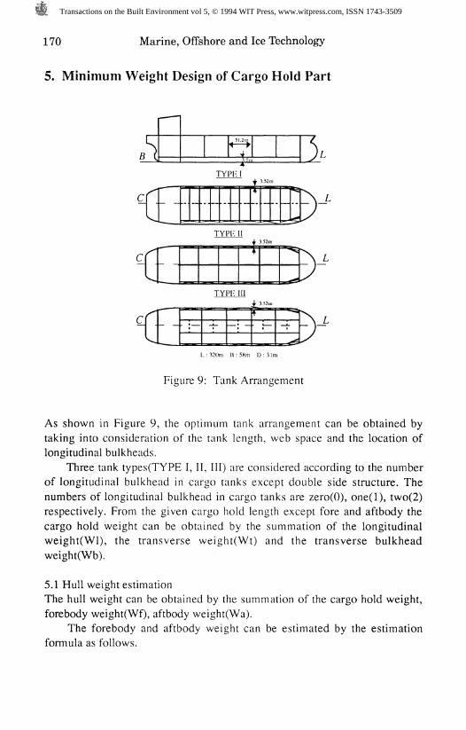
Figure 9: Tank Arrangement
As shown in Figure 9, the optimum tank arrangement can be obtained bytaking into consideration of the tank length, web space and the location oflongitudinal bulkheads.
Three tank types(TYPE I, II, III) are considered according to the numberof longitudinal bulkhead in cargo tanks except double side structure. Thenumbers of longitudinal bulkhead in cargo tanks are zero(O), one(l), two(2)respectively. From the given cargo hold length except fore and aftbody thecargo hold weight can be obtained by the summation of the longitudinalweight(Wl), the transverse weight(Wt) and the transverse bulkheadweight(Wb).
5.1 Hull weight estimationThe hull weight can be obtained by the summation of the cargo hold weight,forebody weight(Wf), aftbody weight(Wa).
The forebody and aftbody weight can be estimated by the estimationformula as follows.
Transactions on the Built Environment vol 5, © 1994 WIT Press, www.witpress.com, ISSN 1743-3509

Marine, Offshore and Ice Technology 171
Hullweight (Ton) = Wl +Wt +Wb +Wf +Wa (4)
Wzcre iy/ = (y, x L J x ( 0.4 + (16 (3+ C )/4 |I n L >m = x N^ +^ x 7V,Jx ( 0.4 + 06 (3+ Cg)/4 )
W/6=(l^ x^\ +M/ %#i)be be bw bw '0.728
My = 160 x (L . x x D x C^ / 1000)0.469
Wa= 530 x (1^ x B x D x C^ / 1000)
W i : weight of longitudinal members per unit length
W^, W^ : weight of web frames in cargo and wing tanks
NIC'^IW '" number of web frames in cargo and wing tanks
^bc'^bw -weight of trans, bulkheads in cargo and wing tanks
TV , N : number of trans, bulkheads in cargo and wing tanks
5.2 Objective functionThe objective function is defined as the hull weight mentioned above.
5.3 Design variablesThe number of transverse bulkheads, the number of web frames and thelocation of longitudinal bulkhead are adopted as parametric design variables.
5.4 ConstraintsAs for constraints, the MARPOL(SBT, PL etc.) convention is adopted for thetank arrangement and is to be checked by the package program SIKOB.
5.5 Design results and discussionsAs shown in Table 1, the hull weight is estimated by the summation of thelongitudinal weight, transverse weight, transverse bulkhead weight, forebodyweight and aft body weight for the DnV and Lloyd classification.
We can see that the hull weights obtained by the DnV and Lloyd rules aresimilar without respect to tank types but the hull weights obtained by the tanktypes are quite different.
TYPE I requires about 20%, TYPE II requires about 15% and TYPE IIIrequires about 13% overweight on the basis of hull weight for theconventional tanker of 300,000 DWT(28,500 Ton)[3]. Therefore, it can besaid that TYPE 111 is proper for the structural design of double hull VLCC.
Conclusively, from the structural design viewpoint, several comparativestudies should be done for the determining optimum tank arrangement andtank type according to ship sizes.
Transactions on the Built Environment vol 5, © 1994 WIT Press, www.witpress.com, ISSN 1743-3509

172 Marine, Offshore and Ice Technology
Table 1 Comparison of Hull Weight with Existing Shipunit: Ton
Lorigi.Weight
Trans.Weight
T. BUDWeight
ForebodyWeightAfterbodyWeight
Netllullweight
CLASS
DnV
Lloyd
DnV
Lloyd
DnV
LloydDnVLloydDnVLloyd
DnV
Lloyd
TYPE I
16603
16657
3024
3276
8344
9248
1446
4002
33419
34629
TYPE II
17559
17608
6613
6760
3178
3104
1446
4002
32798
32920
TYPE III
18597
18651
5598
5000
2648
2757
1446
4002
32291
31855
Note) Weight of Existing Ship (=32700 Ton)(TYPEIII:DnV Base)
As shown in Figure 10, the optimum scantlings are expressed accordingto the scantling format for the DnV classification approval. Also, as shown inFigure 11, optimum design results obtained by the DnV classification rules aredrawn by the graphic library PLOT 10.
|PL.|ACT|T-ACT| TK ||NO.| | (MM)| (MM)|I
IEFF.|TSPAC|LSPAC|I % | (MM) | (MM) |
| SIGFI Fl ||N/MM2| |
II LOG |T-LOC| POS | LOAD|LOC.| SEAM| ZL |CO.NO|SIGMA| p |I | (MM)| | REF.|REF.| (MM)| (MM)| |N/MM2|KN/M2|I II BUG |T-BUG| ETAI I (MM)|
|BUG.| YB | ZB | SIGL| SIGC|SIGCR|IREF.I (MM)| (MM)|N/MM2|N/MM2|N/MM2|
BTM. SHELL
1 ACT 21 .50 1.0LOG 21.26 BOTTBUG 15 .29 0.9
100 910. 315.0 1.281690. 153.6 276.8
164 .4 247 .4 366 .9
Figure 10: Example of Scantling Sheet(TYPE III:DnV Base)
Transactions on the Built Environment vol 5, © 1994 WIT Press, www.witpress.com, ISSN 1743-3509

Marine, Offshore and Ice Technology 173
BIXOOB2 B-BTXDOB3 E 6t X QLLt C'BTX SLiE C 8f X 5//E C OT X CZ E 5' 5IXSZ.62 10'02XOZ
C3CQ
cQ
LLlCL
HS
Q
b/,E
Transactions on the Built Environment vol 5, © 1994 WIT Press, www.witpress.com, ISSN 1743-3509

174 Marine, Offshore and Ice Technology
6. Conclusions
For the optimum structural design of double hull VLCC, minimum weightdesign programs are developed by using the Hooke & Jeeves direct searchmethod for the DnV and Lloyd rules.
The longitudinal members are designed by the classification rules such asDnV, Lloyd and the transverse web frames and bulkheads members aredesigned by the generalized slope deflection method. Three tank types areconsidered according to the number of longitudinal bulkhead in cargo tanks.Total hull weight of optimum design is calculated and compared with that ofexisting design ship.
The main conclusions can be summarized as follows.
(1) The obtained scantlings and hull weight between the DnV and Lloydclassification rules are similar from the viewpoint of classification.
(2) The hull weights for TYPE II, III are similar but that of TYPE I isheavier than those of TYPE II, III from the viewpoint of tank type and it canbe suggested that TYPE III is proper for the structural design of double hullVLCC.
(3) Several comparative studies are necessary to determine the propertank arrangement according to ship sizes.
(4) A minimum cost design of double hull tanker will be studied in futureto reduce the fabrication cost.
References
1. Grove, T., "Study on VLCC with D/B & D/S", Dnl/ c/m\#cafmfz, 1990.2. Jang, C.D., Development of Optimum Structural Design Systems for Oil
7aA%&z/%Y aW Bw/A CoAT/crtY/) , RIIS87-037, Report of EngineeringInstitute of Seoul National University, 1988.
3. Jang, C.D., Development of Optimum Structural Design Systems for OilTankers and Bulk Carriers(ll) , RIES89-036, Report of EngineeringInstitute Seoul National University, 1990.
4. Jang, C.D., Development of Optimum Structural Design Systems for OilTankers and Bulk Carriers(III) , RIES90-052, Report of EngineeringInstitute Seoul National University, 1991.
5. Jang, C.D. and Na, S.S., "Optimum Structural Design of Double Hull OilTankers", /Voc. 4f/z W. CW /zcz C4DMO92, 1992.
6. Lee, H.R., Finite Element Structural Analysis(in Korean), TechnicalReport, Daewoo Shipbuilding & Heavy Machinery Ltd., No.5049-H002,1990.
7. Jang, C.D. and Na, S.S., "On the Minimum Structural Weight Design of
Transactions on the Built Environment vol 5, © 1994 WIT Press, www.witpress.com, ISSN 1743-3509

Marine, Offshore and Ice Technology 175
Oil Tankers by Generalized Slope Deflection Method", PRADS87,Norway, 1987.
8. Jang, CD. and Na, S.S., "Computer Aided Optimum Structural Design ofActual Oil Tankers(VLCC)" , Proc. 2nd Int. Conference CADMO88,1988.
9. Jang, CD. and Na, S.S., "On the Optimum Structural Design of MARPOLTankers Considering Tank Arrangement", Proc. 3rd Int. ConferenceCADMO91, 1991.
10. Na, S.S., "On the Structural Analysis and the Minimum Weight Design ofShip Structures by Generalized Slope Deflection Method", PhD. Thesisof Seoul National University, 1988.
11. Jang, CD. and Na, S.S., "Development of Optimum Structural DesignSystem for Large Double Hull Oil Tankers(in Korean)", AutumnMeeting, the Society of Naval Architects of Korea, 1992.
12. Hooke, R. and Jeeves, T. A., "Direct Search Solution of Numerical andStatistical Problems", ./. of the Assoc. for Computing Machinery, vol.8,No.4, 1961.
Transactions on the Built Environment vol 5, © 1994 WIT Press, www.witpress.com, ISSN 1743-3509