io-540-d4b5 series illustrated parts catalog - … parts...io-540-d4b5 series illustrated parts...
TRANSCRIPT
IO-540-D4B5 Series Illustrated Parts Catalog
April 2015 PC- IO-540-D4B5 652 Oliver Street
Williamsport, PA 17701
© 2015

IO-540-D4B5 Series Illustrated Parts Catalog Lycoming Part Number: PC-IO-540-D4B5 ©2015 Lycoming. All Rights Reserved. Lycoming and “Powered by Lycoming” are trademarks or registered trademarks of Lycoming. Lycoming Engines is a division of Avco Corporation. All brand and product names referenced in this publication are trademarks or registered trademarks of their respective companies.
For additional information: Mailing address: Lycoming Engines 652 Oliver Street Williamsport, PA 17701 U.S.A. Phone: Factory: U.S. and Canada toll free +1(800) 258-3279 International Customers +1(570) 323-6181 Sales Department: +1(570) 327-7278 Fax: +1(570) 327-7101 Lycoming’s regular business hours are Monday through Friday from 8:00 A.M.
through 5:00 P.M. Eastern Time (-5 GMT) Visit us on the World Wide Web at: http://www.lycoming.com
©2015

IO-540-D4B5 Series Illustrated Parts Catalog
Effectivity: IO-540-D4B5 Series Record of Revisions Copyright, Lycoming Engines Page iii Lycoming Engines is a division of Avco Corporation April 2015
RECORD OF REVSIONS
NOTE: Service Documents override parts information in this document.
Rev No. Issue Date Initials Insertion Date

IO-540-D4B5 Series Illustrated Parts Catalog
Record of Revisions Effectivity: IO-540-D4B5 Series Page iv Copyright, Lycoming Engines April 2015 Lycoming Engines is a division of Avco Corporation
This page intentionally left blank.

IO-540-D4B5 Series Illustrated Parts Catalog
Effectivity: IO-540-D4B5 Series Table of Contents Copyright, Lycoming Engines Page v Lycoming Engines is a division of Avco Corporation April 2015
TABLE OF CONTENTS Subject Chapter-Section Page Frontal ________________________________________________________________________
Record of Revisions ............................................................... ........................... …………………iii
Table of Contents ................................................................... ........................... …………………v
Introduction ............................................................................ ........................... …………………vii
Abbreviations and Acronyms .................................................. ........................... …………………xi
Oversize and Undersize Part Listing ...................................... ........................... …………………xiii
Reciprocating Engine _____________________________ 72-00 _________________________
Front Section ........................................................................ 72-10
1. Propeller Governor Drive Assembly .............................. ........................... …………………0-1
Power Section ...................................................................... 72-20
1. Crankcase Assembly .................................................... ........................... …………………2-3
2. Crankcase-Related Parts .............................................. ........................... …………………4-5
3. Crankshaft, Counterweight, Camshaft and Related Parts ......................... …………………6-7
4. Crankshaft and Fuel Pump Idler Gears ......................... ........................... …………………8-9
5. Crankcase Attaching Parts ........................................... ........................... ………………..10-11
Cylinder Section ................................................................... 72-30
1. Connecting Rods, Pistons and Ring Assemblies .......... ........................... ………………..12-13
2. Cylinder Assembly ........................................................ ........................... ………………..14-15
3. Valve Assembly and Related Parts (on Engines with Roller Tappets) ....... ………………..16-19
4. Valve Assembly and Related Parts (on Engines with Straight Body Tappets)……..……..20-23
5. Cylinder-Related Parts.................................................. ........................... ………………..24-25
Lubrication System .............................................................. 72-50
1. Intake Pipes ................................................................. ........................... ………………..26-27
2. Oil Level Gage and Engine Mounting Brackets ............. ........................... ………………..28-29
3. Oil Sump Assembly ...................................................... ........................... ………………..30-31
Accessory Drives ................................................................. 72-60
1. Accessory Housing Assembly ....................................... ........................... ………………..32-33
2. Oil Pump Assembly and Accessory Housing Attaching Parts ................... ………………..34-35
3. Fuel Pump Assembly and Attaching Parts .................... ........................... ………………..36-37
4. Vacuum Pump Drive and Oil Cooler ............................. ........................... ………………..38-39
5. Oil Filter Assembly and Oil Cooler Bypass Valve .......... ........................... ………………..40-41

IO-540-D4B5 Series Illustrated Parts Catalog
Table of Contents Effectivity: IO-540-D4B5 Series Page vi Copyright, Lycoming Engines April 2015 Lycoming Engines is a division of Avco Corporation
Subject Chapter-Section Page
Engine and Fuel Control __________________________ 73-00 _________________________
Fuel Distribution .................................................................. 73-10
1. Fuel Injector, Fuel Lines, and Manifold Assembly………. ......................... ………………..42-45
Ignition Distribution System _______________________ 74-00 _________________________
Distribution .......................................................................... 74-20
1. Magnetos, Magneto Drives and Spark Plugs................ ........................... ………………..46-47
Starting ________________________________________ 80-00 _________________________
Cranking ............................................................................... 80-10
1. Starter Motor and Attaching Parts ................................ ........................... ……….……….48-49
Service Kit Section………………………………………………………………..............................50-53
Numerical Index ................................................................... ........................... ………………..54-58

IO-540-D4B5 Series Illustrated Parts Catalog
Effectivity: IO-540-D4B5 Series Introduction Copyright, Lycoming Engines Page vii Lycoming Engines is a division of Avco Corporation April 2015
INTRODUCTION
DO NOT USE THIS CATALOG AS AN ASSEMBLY OR INSTALLATION DOCUMENT. THIS CATALOG MUST ONLY BE USED TO IDENTIFY PARTS IN CONJUNCTION WITH THE APPLICABLE OVERHAUL MANUAL.
Purpose of This Catalog
This Illustrated Parts Catalog contains a complete list of spare parts for the Lycoming IO-540-D4B5 Certified Series wide cylinder flange model engine.
How to Use This Catalog
This catalog is based on the Air Transport Association (ATA) Spec100 format.
This catalog is frequently updated by Service Bulletins (SB) and Service Instructions (SI). The updated information will be incorporated into subsequent full revisions of this catalog.
The ATA two element numbering system provides consistency throughout various manuals. The bottom of each page (beyond the frontal section) contains a two element number (##-##). In the two element numbering, the first two digits represent a chapter, and the next two digits subdivide the material into a more specific section.
The ATA 100 format designates chapters by the numeric code. In the example below, Chapter 74 is for Ignition with a subsection 20 for Distribution.
EXAMPLE: 74 — 20 Chapter Section
Ignition Distribution
NOTE: Refer to the IPC Table of Contents for the sub-systems listed in each section.
Numerical Index
The Numerical Index is a single list of part numbers, names and their locations within the IPC. It is useful for locating parts when you only know the number of name of the part.
Description column
Indentation of a part name represents a lower level of assembly. Attaching parts have the same indentation level and are listed below the parts grouping or assembly they attach to. This column is often referred to as the “Nomenclature” on other ATA Spec manuals.
Units per Assembly column
Where more than one assembly exists, this column contains the quantity of a specific part required in the build sequence of only one next higher assembly. The Letters “AR” represent “as required” for bulk items or non-illustrated select-from-range-parts. “RF” represents items listed for reference purposes only.

IO-540-D4B5 Series Illustrated Parts Catalog
Introduction Effectivity: IO-540-D4B5 Series Page viii Copyright, Lycoming Engines April 2015 Lycoming Engines is a division of Avco Corporation
Vendor Accessories
Parts coverage of Vendor Accessories used on Lycoming engines may be found in the appropriate Vendor’s Parts Catalog. A list of vendor’s addresses appears in the latest revision of Lycoming Service Letter No. L114.
Any reference in this document to the suppliers/part manufacturer’s product, by name, trademark, part number or other description is solely for the purpose of identification and does not indicate or infer that Lycoming accepts responsibility for quality control and/or airworthiness of parts, which do not pass through the Lycoming quality control system.
Environmental Compliance
Lycoming is concerned with preserving the environment. Lycoming strongly urges engine owners and repair/overhaul personnel to observe and comply with all federal, state, and local environmental regulations when solvents, paint, fuel, oil, chemicals, or other consumables are used in operating, maintaining, or overhauling an engine component. Please share our concern for, and commitment to a clean earth, clean water, and especially clean air for succeeding generations of flyers.

IO-540-D4B5 Series Illustrated Parts Catalog
Effectivity: IO-540-D4B5 Series Introduction Copyright, Lycoming Engines Page ix Lycoming Engines is a division of Avco Corporation April 2015
Perspective of References
In this manual, all references to locations of various components will be designated as if viewing the engine from the rear (or anti-propeller) end. The front of the engine is considered to be the propeller end and the oil sump is considered to be on the bottom of the engine. Cylinders are numbered from front to rear with the odd-numbered cylinders on the right-hand side. The firing order for this engine is 1-4-5-2-3-6.
Top View of Engine

IO-540-D4B5 Series Illustrated Parts Catalog
Introduction Effectivity: IO-540-D4B5 Series Page x Copyright, Lycoming Engines April 2015 Lycoming Engines is a division of Avco Corporation
How to Order Parts and Publications
An Oversize and Undersize Parts List is included in the frontal section of this catalog, to aid in ordering parts as necessary during overhaul.
Although the information contained in this parts catalog is up-to-date at time of publication, users are advised to procure current information through all Lycoming distributors or from the factory by subscription. Refer to the latest revision of Service Letter No. L114 for subscription information.
1. In order to expedite correct part shipments without delay:
a. Always specify the model and serial number of your engine.
b. Always specify part number, nomenclature and quantity required.
The SB and SI documents are available from Lycoming distributors, the factory, or by subscription.
Full Revisions of the Illustrated Parts Catalog are available from Lycoming distributors, or the factory.
Every effort has been made in preparing this manual to ensure its accuracy. However, any comments, suggestions, or corrections to this manual are welcome and must be directed in writing to:
Technical Publications Coordinator Lycoming Engines 652 Oliver Street Williamsport, PA 17701
NOTE: The owner of the manual is responsible for notifying the factory of a change of address.
Additionally, Lycoming has a Customer Service Hot Line to provide information and assistance to owners, operators, and maintenance personnel servicing Lycoming engines.
Call +1-800-258-3279 - U.S. and Canada toll free +1-570-323-6181 - International
8:00 A.M. – 5:00 P.M. EST (-5GMT)
Monday – Friday.
©2015 by Lycoming. “All Rights Reserved.” All Lycoming publications are to be considered copyrighted and may not be reproduced without permission of the company.

IO-540-D4B5 Series Illustrated Parts Catalog
Effectivity: IO-540-D4B5 Series Abbreviations and Acronyms Copyright, Lycoming Engines Page xi Lycoming Engines is a division of Avco Corporation April 2015
ABBREVIATIONS AND ACRONYMS
A
Adj. Adjustable
AR As Required
Assy Assembly
ATA Air Transport Association
C
Cyl. Cylinder
F
Fill. Fillister
H
Hex. Hexagon
I
I.D. Inside Diameter
in. Inch
M
mm Millimeter
N
No. Number
NPT National Pipe Taper (thread)
O
O.D. Outside Diameter
P
P Lycoming Proprietary Part
P/N Part Number
R
RF Reference
S
SB Service Bulletin
SI Service Instruction
T
Temp. Temperature
Thd. Thread
U
UNC Unified National Coarse

IO-540-D4B5 Series Illustrated Parts Catalog
Abbreviations and Acronyms Effectivity: IO-540-D4B5 Series Page xii Copyright, Lycoming Engines April 2015 Lycoming Engines is a division of Avco Corporation
This page intentionally left blank.

IO-540-D4B5 Series Illustrated Parts Catalog
Effectivity: IO-540-D4B5 Series Oversize and Undersize Parts Copyright, Lycoming Engines Page xiii Lycoming Engines is a division of Avco Corporation April 2015
OVERSIZE AND UNDERSIZE PARTS LISTING
NOTE When ordering oversize and undersize parts, be sure to specify the required oversize and undersize dimension along with the proper part number. For example, to order bearing P/N 18A26093 bearing in .003 in. undersize, order P/N 18A26093-M03. Undersize code letter is “M” while oversize code letter is “P”. These letters are then followed by the number designating the size in thousandths of an inch.
* See latest revision of Service Instruction No. 1256. Refer to Figure 8 items 4 and 5 for valve guides ** See latest revision of Service Instruction No. 1143 ♦ See latest revision of Service Instruction No. 1142 † See latest revision of Service Instruction No. 1324
Part No. Description
Undersize (In.) Oversize (In.)
.0015
P05 .005
P10 .010
P15 .015
P20 .020
P30 .030
P40 .040
P50 .050
M03 .003
M06 .006
M10 .010
66610 BUSHING X
61681* GUIDE X X X
66796 INSERT X
69796 STEPPED DOWEL X
18D26096 STRAIGHT DOWEL
X X
72058 SEAT X
71903-A ** BUSHING
72155-S BUSHING X X
16R22291* GUIDE X X
73810 ♦ BUSHING X X X
14H21950 RING X
74241 RING X
75656-S BUSHING X X
75657-S BUSHING X X
LW-13792† SEAL X
72057 SEAT X
18A26093 BEARING X X X
18D26098 BEARING X X X
STD-1065 DOWEL X X

IO-540-D4B5 Series Illustrated Parts Catalog
72-10 Effectivity: IO-540-D4B5 Series Page 0 Copyright, Lycoming Engines April 2015 Lycoming Engines is a division of Avco Corporation
Propeller Governor Drive Assembly Figure 1

IO-540-D4B5 Series Illustrated Parts Catalog
Effectivity: IO-540-D4B5 Series 72-10 Copyright, Lycoming Engines Page 1 Lycoming Engines is a division of Avco Corporation April 2015
FIGURE 1 - PROPELLER GOVERNOR DRIVE ASSEMBLY
Figure Item
Code Part Number Description Units per Assembly
1 LW-10442 GEAR, Propeller governor driven 1
2 LW-14021 SHAFT, Propeller governor idler gear 1
3 LW-10541 GEAR ASSEMBLY, Propeller governor idler 1
4 77872 BUSHING, Propeller governor idler gear 2
5 STD-19 DOWEL, 3/32 diameter x 7/32 long 1
6 STD-798 DOWEL, 3/32 diameter x 9/32 long 1
7 AR 73249 WASHER, Thrust (.0585 - .0595 thick) AR
AR 73250 WASHER, Thrust (.062 - .063 thick) AR
AR 73251 WASHER, Thrust (.0655 - .0665 thick) AR
AR 73252 WASHER, Thrust (.069 - .070 thick) AR
AR 01L21418 WASHER, Thrust (.055 - .056 thick) AR
8 AN565B1032H5 SET SCREW, #10-32 x 5/16 long 1
9 70455 GASKET, 25/32 I.D. x 1-1/8 O.D. x 1/32 thick 1
10 LW-13896 PLUG, 3/4-16 hex. head 1
11 72053 GASKET, Governor 1
12 72378 COVER, Governor drive 1
13 STD-35 WASHER, 5/16 plain 4
14 STD-475 WASHER, 5/16 lock, internal teeth 4
15 STD-1410 NUT, 5/16-18 plain 4
AR as required
IO-540-D4B5 Series Illustrated Parts Catalog
72-20 Effectivity: IO-540-D4B5 Series Page 2 Copyright, Lycoming Engines April 2015 Lycoming Engines is a division of Avco Corporation
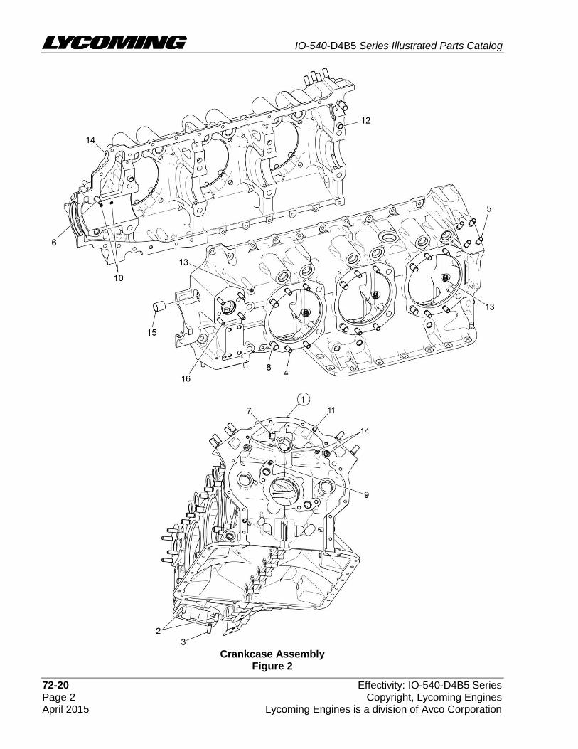
Crankcase Assembly
Figure 2

IO-540-D4B5 Series Illustrated Parts Catalog
Effectivity: IO-540-D4B5 Series 72-20 Copyright, Lycoming Engines Page 3 Lycoming Engines is a division of Avco Corporation April 2015
FIGURE 2 - CRANKCASE ASSEMBLY
Figure Item
Code Part Number Description Units per Assembly
1 * 11E24000-S1-S KIT, CRANKCASE ASSEMBLY -STRAIGHT BODY TAPPET
1
P 11E24000-S1 CRANKCASE ASSEMBLY -STRAIGHT BODY TAPPET
1
* 11E24100-S1-S KIT, CRANKCASE ASSEMBLY-ROLLER LIFTER
1
P 11E24100-S1 CRANKCASE ASSEMBLY-ROLLER LIFTER 1
2 31C-12 STUD, 5/16-18 x 1-1/2 long 2
3 31C-13 STUD, 5/16-18 x 1-5/8 long 1
4 38-13 STUD, 3/8-16 x 1-5/8 long 24
5 38-16 STUD, 3/8-16 x 2.00 long 8
6 38-22 STUD, 3/8-16 x 2-3/4 long 1
7 38D-17 STUD, 3/8-16 x 2-1/8 long, drilled 1
8 50-15 STUD, 1/2-13 x 1-7/8 long 12
9 01A23354 STUD, 5/16-18 x 1.00 long , drilled 1
10 69796 DOWEL, Crankshaft, front bearing 2
11 STD-514 DOWEL, 5/16 diameter x 1/2 long 2
12 STD-557 DOWEL, 1/2 diameter x 11/16 long 2
13 STD-1339 PLUG, 1/16-27 NPT, Allen head 7
14 1102 PLUG, 1/8 pipe, Allen head 4
15 72158 BUSHING, Governor drive idler shaft 1
16 31C-17 STUD, 5/16-18 x 2-1/8 long 4
P Lycoming proprietary part. Listed for reference purposes only, cannot be purchased.
* Refer to the Service Kit Section in this parts catalog for applicable Crankcase Assembly Thru- Stud Kit Part Numbers.
See latest revision of Service Instruction No. 1514 for shroud tube spring information.
Refer to Service Instruction Nos. SI-1011 and 1514

IO-540-D4B5 Series Illustrated Parts Catalog
72-20 Effectivity: IO-540-D4B5 Series Page 4 Copyright, Lycoming Engines April 2015 Lycoming Engines is a division of Avco Corporation

IO-540-D4B5 Series Illustrated Parts Catalog
Effectivity: IO-540-D4B5 Series 72-20 Copyright, Lycoming Engines Page 5 Lycoming Engines is a division of Avco Corporation April 2015
Crankcase-Related Parts Figure 3
FIGURE 3 – CRANKCASE-RELATED PARTS
Figure Item
Code Part Number Description Units per Assembly
1 1028-B BALL, 11/16 diameter 1
2 * 68668 SPRING, Oil pressure relief valve 1
* 61084 SPRING, Oil pressure relief valve 1
* LW-11713 SPRING, Oil pressure relief valve 1
* LW-18085 SPRING, Oil pressure relief valve 1
* 77467 SPRING, Oil pressure relief valve 1
3 06E19769-1.25 GASKET, 1-1/4 I.D. annular 1
4 77808 VALVE ASSEMBLY, Oil pressure relief, adj. 1
5 18D26098 BEARING, Crankshaft 6
6 18A26093 BEARING, Crankshaft, front 2
7 ♦ LW-13792 SEAL, Crankshaft oil 1
8 72091 RING, Oil seal, 23/64 I.D. x 7/64 dia. section 2
9 + 15B26262 BODY ASSEMBLY, Hydraulic tappet 12
+ LRT23381 BODY ASSEMBLY, Hydraulic (roller tappet) 12
* Select spring to give a minimum of three threads exposed on adjusting screw to allow field adjustment. Refer to the latest revision of SSP-1776, Part I for spring identification.
♦ Refer to latest revision of Service Instruction No. 1324 for installation.
+ Refer to the latest revision of Service Instruction Nos. S.I. 1011 and 1514.

IO-540-D4B5 Series Illustrated Parts Catalog
72-20 Effectivity: IO-540-D4B5 Series Page 6 Copyright, Lycoming Engines April 2015 Lycoming Engines is a division of Avco Corporation

IO-540-D4B5 Series Illustrated Parts Catalog
Effectivity: IO-540-D4B5 Series 72-20 Copyright, Lycoming Engines Page 7 Lycoming Engines is a division of Avco Corporation April 2015
Crankshaft, Counterweight, Camshaft, and Related Parts Figure 4
FIGURE 4 - CRANKSHAFT, COUNTERWEIGHT, CAMSHAFT, AND RELATED PARTS
Figure Item
Code Part Number Description Units per Assembly
1 13E47622 CRANKSHAFT ASSEMBLY 1
2 71640 PLUG, 1.38 diameter expansion 1
3 75656-S BUSHING, Propeller flange, long 4
4 72155-S BUSHING, Propeller flange, short 1
5 75657-S BUSHING, Propeller flange, indexing 1
6 STD-1065 DOWEL, Stepped, 5/16 & 1/4 dia. x 35/64 1
7 73810 BUSHING, Crankshaft, counterweight 4
8 * LW-19227 COUNTERWEIGHT ASSEMBLY 2
9 71903-A BUSHING, Dynamic counterweight 4
10 * 72797 ROLLER, Dynamic counterweight, 6.3 order 2
11 * 72965 ROLLER, Dynamic counterweight 2
12 LW-14820 RING, Internal retaining 8
13 71907 WASHER, Dynamic counterweight 8
14 STD-1211 PLUG, 2.00 diameter expansion 1
15 ** 13S19647 GEAR, Crankshaft 1
16 LW-18638 LOCKPLATE, Crankshaft gear 1
17 STD-2247 BOLT, 5/16-24 x 1.75 1
18 15N23374 CAMSHAFT ASSEMBLY, roller lifter 1
LW-19340 CAMSHAFT ASSEMBLY 1
19 76118 SPACER, Tachometer shaft centering 1
20 76155 SHAFT ASSEMBLY, Tachometer 1
21 LW-18667 PIN, 3/16 diameter x 2-21/64 long 1
22 STD-2231 RING, Internal retaining 1
23 LW-18633 SUPPORT ASSEMBLY, Starter ring gear 1
31M22045 SUPPORT ASSEMBLY, Starter ring gear 1
24 72566 GEAR, Starter ring 1
* Refer to the latest revision of Service Instruction No. 1535 for counterweight and roller installation.
** Refer to the latest revision of Service Bulletin No. 475 for installation.

IO-540-D4B5 Series Illustrated Parts Catalog
72-20 Effectivity: IO-540-D4B5 Series Page 8 Copyright, Lycoming Engines April 2015 Lycoming Engines is a division of Avco Corporation
Crankshaft and Fuel Pump Idler Gears

IO-540-D4B5 Series Illustrated Parts Catalog
Effectivity: IO-540-D4B5 Series 72-20 Copyright, Lycoming Engines Page 9 Lycoming Engines is a division of Avco Corporation April 2015
Figure 5 FIGURE 5 – CRANKSHAFT AND FUEL PUMP IDLER GEARS
Figure Item
Code Part Number Description Units per Assembly
1 LW-13795 SHAFT, Crankshaft idler gear 2
2 LW-31H0.88 BOLT, 5/16-18 x 7/8 long, hex head, drilled 3
3 STD-2168 NUT, 5/16-18 NC, slotted, shear 1
4 23D26777 PLUNGER, Fuel pump, long 1
5 71652 GEAR ASSEMBLY, Crankshaft idler 1
6 67530 BUSHING, Crankshaft idler gear 1
7 71668 GEAR ASSEMBLY, Crankshaft idler, plain 1
8 67530 BUSHING, Crankshaft idler gear 1

IO-540-D4B5 Series Illustrated Parts Catalog
72-20 Effectivity: IO-540-D4B5 Series Page 10 Copyright, Lycoming Engines April 2015 Lycoming Engines is a division of Avco Corporation
Crankcase Attaching Parts Figure 6

IO-540-D4B5 Series Illustrated Parts Catalog
Effectivity: IO-540-D4B5 Series 72-20 Copyright, Lycoming Engines Page 11 Lycoming Engines is a division of Avco Corporation April 2015
FIGURE 6 - CRANKCASE ATTACHING PARTS
Figure Item
Code Part Number Description Units per Assembly
1 60803 STRAP, Lifting 2
2 LW-25-1.50 BOLT, 1/4-20 x 1-1/2 long, hex. head 8
3 STD-8 WASHER, 1/4 plain 22
4 LW-25-1.88 BOLT, 1/4-20 x 1-3/4 long, hex. head 1
5 LW-25-2.00 BOLT, 1/4-20 x 2.00 long, hex. head 2
6 LW-25-1.75 BOLT, 1/4-20 x 1-3/4 long, hex. head 1
7 LW-25-1.13 BOLT, 1/4-20 x 1-1/8 long, hex. head 1
8 STD-160 WASHER, 1/4 lock, internal teeth 13
9 STD-1411 NUT, 1/4-20 plain 12
10 LW-25S1.50 BOLT, 1/4-20 x 1-1/2 long, hex. head, drilled 6
11 STD-8 WASHER, 1/4 plain 18
12 STD-2249 NUT, 1/4-20 slotted shear 6
13 STD-33 WASHER, 3/8 plain 1
14 STD-872 NUT, 3/8-24 slotted 1
15 AN6-34A BOLT, 3/8-24 x 3-9/16 long, hex. head 1
16 STD-33 WASHER, 3/8 plain 3
17 STD-678 WASHER, 3/8 lock, internal teeth 2
18 STD-596 NUT, 3/8-24 plain 2
19 76220 STUD, 1/2-20 x 10-45/64 long 8
20 LW-31-2.75 BOLT, 5/16-18 x 2-3/4 long, hex. head 1
21 LW-31-1.16 BOLT, 5/16-18 x 1-5/32 long, hex. head 3
22 STD-35 WASHER, 5/16 plain 4
23 STD-475 WASHER, 5/16 lock, internal teeth 4

IO-540-D4B5 Series Illustrated Parts Catalog
72-30 Effectivity: IO-540-D4B5 Series Page 12 Copyright, Lycoming Engines April 2015 Lycoming Engines is a division of Avco Corporation
Connecting Rods, Pistons, and Ring Assemblies Figure 7

IO-540-D4B5 Series Illustrated Parts Catalog
Effectivity: IO-540-D4B5 Series 72-30 Copyright, Lycoming Engines Page 13 Lycoming Engines is a division of Avco Corporation April 2015
FIGURE 7 - CONNECTING RODS, PISTONS, AND RING ASSEMBLIES
Figure Item
Code Part Number Description Units per Assembly
1 P LW-11750 CONNECTING ROD ASSEMBLY 6
LW-11750-S CONNECTING ROD ASSEMBLY 6
2 P LW-13923 BUSHING, Connecting rod, upper 6
3 P 14S23890 BOLT, Connecting rod 12
* 75061 BOLT, Connecting rod 12
4 LW-12186 NUT, Connecting rod bolt 12
5 18M26105 BEARING, Connecting rod 12
6 14D23912 PISTON, Compression ratio, 8.50:1 6
7 LW-14078 PIN, Piston 6
8 72198 PLUG, Piston pin 12
9 74241 RING, Piston compression 12
10 14H21950 RING, Piston, oil regulating, expander type 6
P Lycoming proprietary part. Listed for reference purposes only, cannot be purchased.
* Service use only.

IO-540-D4B5 Series Illustrated Parts Catalog
72-30 Effectivity: IO-540-D4B5 Series Page 14 Copyright, Lycoming Engines April 2015 Lycoming Engines is a division of Avco Corporation
Cylinder Assembly Figure 8

IO-540-D4B5 Series Illustrated Parts Catalog
Effectivity: IO-540-D4B5 Series 72-30 Copyright, Lycoming Engines Page 15 Lycoming Engines is a division of Avco Corporation April 2015
FIGURE 8 - CYLINDER ASSEMBLY
Figure Item
Code Part Number Description Units per Assembly
1 LW-12427 CYLINDER ASSEMBLY, Nitrided 6
2 72057 SEAT, Intake valve 6
3 72058 SEAT, Exhaust valve 6
4 P * 76943 GUIDE, Valve, intake, flangeless 6
5 P * 16R22126 GUIDE, Valve, exhaust, flangeless 6
6 66796 INSERT, Spark plug, 18-1.5 mm 12
7 STD-1353 INSERT, #10-24 UNC, 3/4 long 6
8 31C-12 STUD, 5/16-18 x 1-1/2 long 12
9 25C-8 STUD, 1/4-20 x 1.00 long 1
10 66610 BUSHING, Rocker shaft, inner 24
11 75118 GASKET, Exhaust flange 6
12 STD-35 WASHER, 5/16 plain 12
13 STD-2043 NUT, 5/16-18, self locking 12
14 1102 PLUG, 1/8 pipe, Allen head 6
15 MS20823-6D ELBOW, 45 degree, 3/8 flared tube 6
P Lycoming proprietary part. Listed for reference purposes only, cannot be purchased.
* Refer to latest revision of Service Instruction No. 1256 for valve guides for service use.

IO-540-D4B5 Series Illustrated Parts Catalog
72-30 Effectivity: IO-540-D4B5 Series Page 16 Copyright, Lycoming Engines April 2015 Lycoming Engines is a division of Avco Corporation
Valve Assembly and Related Parts (on Engines with Roller Tappets) Figure 9

IO-540-D4B5 Series Illustrated Parts Catalog
Effectivity: IO-540-D4B5 Series 72-30 Copyright, Lycoming Engines Page 17 Lycoming Engines is a division of Avco Corporation April 2015
FIGURE 9 – VALVE ASSEMBLY AND RELATED PARTS (ON ENGINES WITH ROLLER TAPPETS)
(continued on next page)
Figure Item
Code Part Number Description Units per Assembly
1 17A23938 VALVE, Intake 6
2 17B23936 VALVE, Exhaust 6
3 LW-11795 SPRING, Valve, inner 12
4 LW-11800 SPRING, Valve, outer 12
5 65441 SEAT, Valve spring, lower intake 6
6 LW-13323 SEAT, Valve spring, lower exhaust 6
7 LW-10077 SEAT, Valve spring, upper intake 6
8 LW-16475 SEAT, Valve spring, upper exhaust 6
9 60009 KEY, Valve, intake 12
10 17C21191 KEY, Valve, exhaust 12
11 17C19386 CAP, Valve stem, exhaust (rotator type) 6
12 15B26066 PLUNGER ASSEMBLY, Hydraulic lifter 12
13 15B21319 SOCKET, Hydraulic lifter 12
14 15G23461 SHROUD TUBE ASSEMBLY, Push rod 12
15 * LW-14995 SPRING, Shroud tube 6
16 LW-12272 LOCKPLATE, Shroud tube 6
17 STD-1411 NUT,1/4-20, plain 6
18 70310 SEAL, Shroud tube 12
19 01L23459 WASHER, 13/32 I.D. x 1-3/8 O.D. x 0.041 12
20 06A23493 SEAL, Shroud tube 12
NOTE: Various push rod lengths are used to set valve clearances.
* See latest revision of Service Instruction No. 1514 for shroud tube spring information.

IO-540-D4B5 Series Illustrated Parts Catalog
72-30 Effectivity: IO-540-D4B5 Series Page 18 Copyright, Lycoming Engines April 2015 Lycoming Engines is a division of Avco Corporation
FIGURE 9 - VALVE ASSEMBLY AND RELATED PARTS (ON ENGINES WITH ROLLER TAPPETS) (CONT.)
Figure Item
Code Part Number Description Units per Assembly
21 AR * 15F19957-28 ROD ASSEMBLY, Push (A total of 12 required) AR
AR * 15F19957-29 ROD ASSEMBLY, Push (A total of 12 required) AR
AR * 15F19957-30 ROD ASSEMBLY, Push (A total of 12 required) AR
AR * 15F19957-31 ROD ASSEMBLY, Push (A total of 12 required) AR
AR * 15F19957-32 ROD ASSEMBLY, Push (A total of 12 required) AR
AR * 15F19957-33 ROD ASSEMBLY, Push (A total of 12 required) AR
AR * 15F19957-34 ROD ASSEMBLY, Push (A total of 12 required) AR
22 ** 17F19357 ROCKER ASSEMBLY, Valve, intake and exhaust
12
23 LW-12892 THRUST BUTTON, Rocker shaft 12
24 LW-13790 SHAFT, Valve rocker 6
AR as required
* Various push rod lengths are used to set valve clearances. Refer to the latest revision of Service Instruction No. 1060 for complete push rod application.
** Due to the size of the area where the number is stamped, the last five digits may be all that is shown (19357).
IO-540-D4B5 Series Illustrated Parts Catalog
Effectivity: IO-540-D4B5 Series 72-30 Copyright, Lycoming Engines Page 19 Lycoming Engines is a division of Avco Corporation April 2015
This page intentionally left blank.

IO-540-D4B5 Series Illustrated Parts Catalog
72-30 Effectivity: IO-540-D4B5 Series Page 20 Copyright, Lycoming Engines April 2015 Lycoming Engines is a division of Avco Corporation
Valve Assembly and Related Parts (on Engines with Straight-Body Tappets) Figure 9A

IO-540-D4B5 Series Illustrated Parts Catalog
Effectivity: IO-540-D4B5 Series 72-30 Copyright, Lycoming Engines Page 21 Lycoming Engines is a division of Avco Corporation April 2015
FIGURE 9A – VALVE ASSEMBLY AND RELATED PARTS (ON ENGINES WITH STRAIGHT-BODY TAPPETS)
(continued on next page)
Figure Item
Code Part Number Description Units per Assembly
1 17A23938 VALVE, Intake 6
2 17B23936 VALVE, Exhaust 6
3 LW-11795 SPRING, Valve, inner 12
4 LW-11800 SPRING, Valve, outer 12
5 65441 SEAT, Valve spring, lower intake 6
6 LW-13323 SEAT, Valve spring, lower exhaust 6
7 LW-10077 SEAT, Valve spring, upper intake 6
8 LW-16475 SEAT, Valve spring, upper exhaust 6
9 60009 KEY, Valve, intake 12
10 17C21191 KEY, Valve, exhaust 12
11 17C19386 CAP, Valve stem, exhaust (rotator type) 6
12 15B26066 PLUNGER ASSEMBLY, Hydraulic lifter 12
13 15B21319 SOCKET, Hydraulic lifter 12
14 LW-11485 SHROUD TUBE ASSEMBLY, Push rod 12
15 * LW-14995 SPRING, Shroud tube 6
16 LW-12272 LOCKPLATE, Shroud tube 6
17 STD-1411 NUT,1/4-20, plain 6
18 LW-18661 SEAL, Shroud tube 12
19 70310 SEAL, Shroud tube 12
NOTE: Various push rod lengths are used to set valve clearances.
* See latest revision of Service Instruction No. 1514 for shroud tube spring information.

IO-540-D4B5 Series Illustrated Parts Catalog
72-30 Effectivity: IO-540-D4B5 Series Page 22 Copyright, Lycoming Engines April 2015 Lycoming Engines is a division of Avco Corporation
FIGURE 9A - VALVE ASSEMBLY AND RELATED PARTS (ON ENGINES WITH STRAIGHT BODY TAPPETS) (CONT.)
Figure Item
Code Part Number Description Units per Assembly
20 AR * 15F19957-34 ROD ASSEMBLY, Push (A total of 12 required) AR
AR * 15F19957-35 ROD ASSEMBLY, Push (A total of 12 required) AR
AR * 15F19957-36 ROD ASSEMBLY, Push (A total of 12 required) AR
AR * 15F19957-37 ROD ASSEMBLY, Push (A total of 12 required) AR
21 ** 17F19357 ROCKER ASSEMBLY, Valve, intake and exhaust
12
22 LW-12892 THRUST BUTTON, Rocker shaft 12
23 LW-13790 SHAFT, Valve rocker 6
AR as required
* Various push rod lengths are used to set valve clearances. Refer to the latest revision of Service Instruction No. 1060 for complete push rod application.
** Due to the size of the area where the number is stamped, the last five digits could be all that is shown (19357).

IO-540-D4B5 Series Illustrated Parts Catalog
Effectivity: IO-540-D4B5 Series 72-30 Copyright, Lycoming Engines Page 23 Lycoming Engines is a division of Avco Corporation April 2015
This page intentionally left blank

IO-540-D4B5 Series Illustrated Parts Catalog
72-30 Effectivity: IO-540-D4B5 Series Page 24 Copyright, Lycoming Engines April 2015 Lycoming Engines is a division of Avco Corporation
Cylinder-Related Parts Figure 10

IO-540-D4B5 Series Illustrated Parts Catalog
Effectivity: IO-540-D4B5 Series 72-30 Copyright, Lycoming Engines Page 25 Lycoming Engines is a division of Avco Corporation April 2015
FIGURE 10 – CYLINDER-RELATED PARTS
Figure Item
Code Part Number Description Units per Assembly
1 75906 GASKET, Rocker box cover 6
2 61247 COVER ASSEMBLY, Rocker box 6
3 STD-1925 SCREW, 1/4-20 x 5/8 long, pan. head, self-locking
36
4 71481 RING, Oil seal, 3/32 diameter x 4-27/32 I.D. 6
5 77906 SPACER, 33/64 I.D. x 7/8 O.D. x 1/8 thick 2
6 74887 SPACER, 33/64 I.D. x 7/8 O.D. x 3/8 thick 2
7 383-B NUT, 3/8-24 plain 24
8 STD-2090 NUT, 1/2-20 plain 28
9 STD-684 NIPPLE, Straight, 3/8 I.D. hose 6
10 STD-1821 HOSE, 3/8 I.D. x 2.50 long 6
11 LW-15592-5-05 CLAMP, Hose 12
12 68759 TUBE ASSEMBLY,Cyl. head oil drain, cyl. no.1 1
13 71737 TUBE ASSEMBLY,Cyl. head oil drain, cyl. no. 2 1
14 68761 TUBE ASSEMBLY,Cyl. head oil drain, cyl. no. 3,4,5,6
4
15 75339 BAFFLE ASSEMBLY, Intercylinder 3
16 LW-13389 BAFFLE ASSEMBLY, Intercylinder 1
17 71610 HOOK, Intercylinder baffle retainer 4
18 71611 RETAINER, Intercylinder baffle 4
19 * MS35489-20X GROMMET 1
* Install in LW-13389 baffle.

IO-540-D4B5 Series Illustrated Parts Catalog
72-50 Effectivity: IO-540-D4B5 Series Page 26 Copyright, Lycoming Engines April 2015 Lycoming Engines is a division of Avco Corporation
Intake Pipes Figure 11

IO-540-D4B5 Series Illustrated Parts Catalog
Effectivity: IO-540-D4B5 Series 72-50 Copyright, Lycoming Engines Page 27 Lycoming Engines is a division of Avco Corporation April 2015
FIGURE 11 – INTAKE PIPES
Figure Item
Code Part Number Description Units per Assembly
1 70485 PIPE, Intake 6
2 69603 HOSE, 1-3/4 I.D. x 2-3/16 O.D. x 1.75 6
3 LW-15592-8-28 CLAMP, Hose 12
4 71973 GASKET, 2 bolt flange, 1-13/16 I.D. 6
5 73346 FLANGE, Intake pipe, upper 6
6 STD-8 WASHER, 1/4 plain 12
7 STD-160 WASHER, 1/4 lock, internal teeth 12
8 LW-25-1.25 BOLT, 1/4-20 x 1-1/4 long, hex. head 12
9 70484 SCREEN, Oil suction 1
10 06E19769-1.00 GASKET, Annular, 1.00 I.D. 1
11 LW-12545 PLUG, 5/8 hex head x 1.00-20 thread 1

IO-540-D4B5 Series Illustrated Parts Catalog
72-50 Effectivity: IO-540-D4B5 Series Page 28 Copyright, Lycoming Engines April 2015 Lycoming Engines is a division of Avco Corporation
Oil Level Gage and Engine Mounting Brackets Figure 12

IO-540-D4B5 Series Illustrated Parts Catalog
Effectivity: IO-540-D4B5 Series 72-50 Copyright, Lycoming Engines Page 29 Lycoming Engines is a division of Avco Corporation April 2015
FIGURE 12 – OIL LEVEL GAGE AND ENGINE MOUNTING BRACKETS
Figure Item
Code Part Number Description Units per Assembly
1 70457 GASKET, Oil filler extension 1
2 77527 EXTENSION, Oil filler (2-3/16 long) 1
75675 EXTENSION, Oil filler (2-3/16 long) 1
3 72312 O-RING, Oil level gage 1
74065 O-RING, Oil level gage 1
4 LW-14732 GAGE ASSEMBLY, Oil level 1
LW-16783-24 GAGE ASSEMBLY, Oil level 1
5 12A19770 BRACKET, Engine mounting (dynafocal) 4
6 STD-33 WASHER, 3/8 plain 16
7 STD-678 WASHER, 3/8 lock, internal teeth 16
8 STD-596 NUT, 3/8-24 plain 16

IO-540-D4B5 Series Illustrated Parts Catalog
72-60 Effectivity: IO-540-D4B5 Series Page 30 Copyright, Lycoming Engines April 2015 Lycoming Engines is a division of Avco Corporation
Oil Sump Assembly Figure 13

IO-540-D4B5 Series Illustrated Parts Catalog
Effectivity: IO-540-D4B5 Series 72-60 Copyright, Lycoming Engines Page 31 Lycoming Engines is a division of Avco Corporation April 2015
FIGURE 13 – OIL SUMP ASSEMBLY
Figure Item
Code Part Number Description Units per Assembly
1 06B21326 GASKET, Oil sump 1
2 LW-13901 SUMP ASSEMBLY, Oil 1
3 71699 CONNECTION, intake pipe 6
4 25C-11 STUD, 1/4-20 x 1-3/8 long 14
5 31C-15 STUD, 5/16-18 x 1-7/8 long 4
6 38-15 STUD, 3/8-16 x 1-7/8 long 8
7 STD-1173 INSERT, 1/4-20 UNC x 1/2 long 4
8 STD-8 WASHER, 1/4 plain 34
9 STD-160 WASHER, 1/4 lock, internal teeth 27
10 LW-25-1.13 BOLT, 1/4-20 x 1-1/8 long, hex. head 7
11 LW-25-1.00 BOLT, 1/4-20 x 1.00 long, hex. head 6
12 STD-1411 NUT, 1/4-20 plain 21
13 STD-551 PLUG, 1/2-14 NPT, square head, drilled 2
14 STD-2229 PLUG, 1/2-14 NPT, Allen head 2

IO-540-D4B5 Series Illustrated Parts Catalog
72-60 Effectivity: IO-540-D4B5 Series Page 32 Copyright, Lycoming Engines April 2015 Lycoming Engines is a division of Avco Corporation
Accessory Housing Assembly Figure 14

IO-540-D4B5 Series Illustrated Parts Catalog
Effectivity: IO-540-D4B5 Series 72-60 Copyright, Lycoming Engines Page 33 Lycoming Engines is a division of Avco Corporation April 2015
FIGURE 14 – ACCESSORY HOUSING ASSEMBLY
Figure Item
Code Part Number Description Units per Assembly
1 73818 GASKET, Accessory housing 1
2 21C21539-02 HOUSING ASSEMBLY, Accessory 1
3 31C-12 STUD, 5/16-18 x 1-1/2 long 4
4 31CD-17 STUD, 5/16-18 x 2-1/8 long, drilled 3
5 31C-21 STUD, 5/16-18 x 2-5/8 long 4
6 25C-21 STUD, 1/4-20 x 2-5/8 long 4
7 STD-784 PLUG, 3/8-18 NPT, Allen head 1
8 1102 PLUG, 1/8-27 NPT, Allen head 4
9 76156 SHIELD, Oil accessory 1

IO-540-D4B5 Series Illustrated Parts Catalog
72-60 Effectivity: IO-540-D4B5 Series Page 34 Copyright, Lycoming Engines April 2015 Lycoming Engines is a division of Avco Corporation
Oil Pump Assembly and Accessory Housing Attaching Parts Figure 15

IO-540-D4B5 Series Illustrated Parts Catalog
Effectivity: IO-540-D4B5 Series 72-60 Copyright, Lycoming Engines Page 35 Lycoming Engines is a division of Avco Corporation April 2015
FIGURE 15 – OIL PUMP ASSEMBLY AND ACCESSORY HOUSING ATTACHING PARTS
Figure Item
Code Part Number Description Units per Assembly
1 78531 BODY ASSEMBLY, Oil pump 1
2 05K19423-S IMPELLER KIT 1
3 * LW-18110 IMPELLER ASSEMBLY, Oil pump driven 1
4 * LW-18109 IMPELLER, Pump driving 1
5 STD-35 WASHER, 5/16 plain 3
6 STD-1420 NUT, 5/16-18 slotted 3
7 LW-14260 SEAL, Tachometer drive, oil 1
8 STD-8 WASHER, 1/4 plain 12
9 STD-160 WASHER, 1/4 lock, internal teeth 12
10 LW-25-0.94 BOLT, 1/4-20 x 15/16 long, hex. head 9
11 LW-25-1.13 BOLT, 1/4-20 x 1-1/8 long, hex. head 1
12 LW-25-1.44 BOLT, 1/4-20 x 1-7/16 long, hex. head 2
13 74641 SHAFT, Oil pump drive 1
* Sold in complete sets only (Kit P/N 05K19423-S).
IO-540-D4B5 Series Illustrated Parts Catalog
72-60 Effectivity: IO-540-D4B5 Series Page 36 Copyright, Lycoming Engines April 2015 Lycoming Engines is a division of Avco Corporation
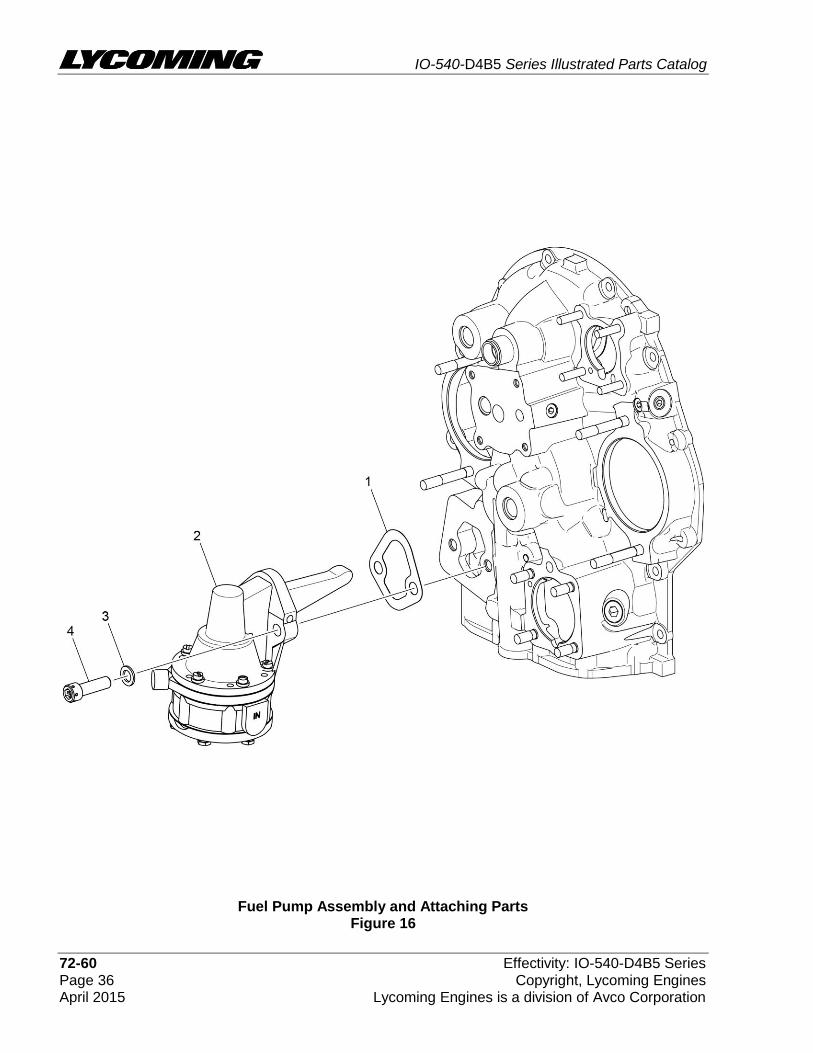
Fuel Pump Assembly and Attaching Parts Figure 16

IO-540-D4B5 Series Illustrated Parts Catalog
Effectivity: IO-540-D4B5 Series 72-60 Copyright, Lycoming Engines Page 37 Lycoming Engines is a division of Avco Corporation April 2015
FIGURE 16 – FUEL PUMP ASSEMBLY AND ATTACHING PARTS
Figure Item
Code Part Number Description Units per Assembly
1 60096 GASKET, Fuel pump 1
2 V 62B26931 FUEL PUMP (High Pressure) 1
3 STD-33 WASHER, 3/8 plain 2
4 STD-1882 SCREW, 3/8-16 x 1-9/32 long, socket head, drilled 2
V Vendor Prime Manufacturer part

IO-540-D4B5 Series Illustrated Parts Catalog
72-60 Effectivity: IO-540-D4B5 Series Page 38 Copyright, Lycoming Engines April 2015 Lycoming Engines is a division of Avco Corporation
Vacuum Pump Drive and Oil Cooler Figure 17
IO-540-D4B5 Series Illustrated Parts Catalog
Effectivity: IO-540-D4B5 Series 72-60 Copyright, Lycoming Engines Page 39 Lycoming Engines is a division of Avco Corporation April 2015
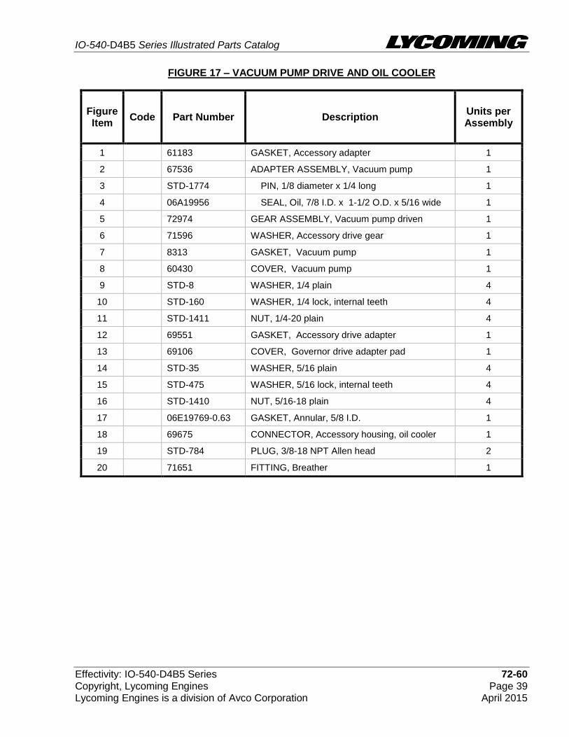
FIGURE 17 – VACUUM PUMP DRIVE AND OIL COOLER
Figure Item
Code Part Number Description Units per Assembly
1 61183 GASKET, Accessory adapter 1
2 67536 ADAPTER ASSEMBLY, Vacuum pump 1
3 STD-1774 PIN, 1/8 diameter x 1/4 long 1
4 06A19956 SEAL, Oil, 7/8 I.D. x 1-1/2 O.D. x 5/16 wide 1
5 72974 GEAR ASSEMBLY, Vacuum pump driven 1
6 71596 WASHER, Accessory drive gear 1
7 8313 GASKET, Vacuum pump 1
8 60430 COVER, Vacuum pump 1
9 STD-8 WASHER, 1/4 plain 4
10 STD-160 WASHER, 1/4 lock, internal teeth 4
11 STD-1411 NUT, 1/4-20 plain 4
12 69551 GASKET, Accessory drive adapter 1
13 69106 COVER, Governor drive adapter pad 1
14 STD-35 WASHER, 5/16 plain 4
15 STD-475 WASHER, 5/16 lock, internal teeth 4
16 STD-1410 NUT, 5/16-18 plain 4
17 06E19769-0.63 GASKET, Annular, 5/8 I.D. 1
18 69675 CONNECTOR, Accessory housing, oil cooler 1
19 STD-784 PLUG, 3/8-18 NPT Allen head 2
20 71651 FITTING, Breather 1

IO-540-D4B5 Series Illustrated Parts Catalog
72-60 Effectivity: IO-540-D4B5 Series Page 40 Copyright, Lycoming Engines April 2015 Lycoming Engines is a division of Avco Corporation
Oil Filter Assembly And Oil Cooler Bypass Valve Figure 18

IO-540-D4B5 Series Illustrated Parts Catalog
Effectivity: IO-540-D4B5 Series 72-60 Copyright, Lycoming Engines Page 41 Lycoming Engines is a division of Avco Corporation April 2015
FIGURE 18 – OIL FILTER ASSEMBLY AND OIL COOLER BYPASS VALVE
Figure Item
Code Part Number Description Units per Assembly
1 06B23862 GASKET, Oil filter adapter 1
2 77852 BASE ASSEMBLY, Oil filter 1
3 V LW-13215 OIL FILTER, Short, (V CH48110-1) 1
4 STD-8 WASHER, 1/4 plain 4
5 STD-160 WASHER, 1/4 lock, internal teeth 4
6 STD-1411 NUT, 1/4-20 plain 1
7 LW-25-1.00 BOLT, 1/4-20 x 1.00 long, hex. head 3
8 53E22144 VALVE ASSEMBLY, with gasket, Temp. control, oil cooler bypass
1
9 25C-10 STUD, 1/4-20 x 1.25 long 1
V Vendor Prime Manufacturer part
IO-540-D4B5 Series Illustrated Parts Catalog
73-10 Effectivity: IO-540-D4B5 Series Page 42 Copyright, Lycoming Engines April 2015 Lycoming Engines is a division of Avco Corporation
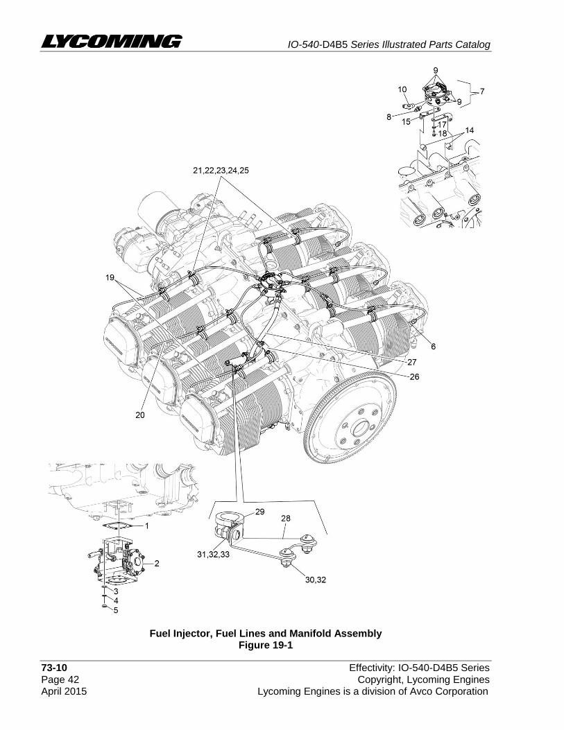
Fuel Injector, Fuel Lines and Manifold Assembly Figure 19-1

IO-540-D4B5 Series Illustrated Parts Catalog
Effectivity: IO-540-D4B5 Series 73-10 Copyright, Lycoming Engines Page 43 Lycoming Engines is a division of Avco Corporation April 2015
Fuel Injector, Fuel Lines and Manifold Assembly Figure 19-2

IO-540-D4B5 Series Illustrated Parts Catalog
73-10 Effectivity: IO-540-D4B5 Series Page 44 Copyright, Lycoming Engines April 2015 Lycoming Engines is a division of Avco Corporation
FIGURES 19-1, 19-2 - FUEL INJECTOR, FUEL LINES AND MANIFOLD ASSEMBLY
Figure Item
Code Part Number Description Units per Assembly
1 66224 GASKET 1
2 61J26426 FUEL INJECTOR (2524054-11) 1
61J26427 FUEL INJECTOR (2576544-3) 1
3 STD-35 WASHER, 5/16 plain 4
4 STD-475 WASHER, 5/16 lock, internal teeth 4
5 STD-1410 NUT, 5/16-18, plain 4
6 63C26450 NOZZLE, Injection (2524864-2) 6
7 63B26725 MANIFOLD ASSEMBLY, Fuel 1
63B26717 MANIFOLD ASSEMBLY, Fuel 1
63B26714 MANIFOLD ASSEMBLY, Fuel 1
8 02G21446 NIPPLE, 1/8 NPT to 1/4 tube 1
9 STD-148 NIPPLE, Union, 1/8 NPT 6
10 MS20823-4 ELBOW, 1/8 NPT to 1/4 fl tube 1
11 MS20822-4 ELBOW, 1/8 NPT to 1/4 fl tube, 90 1
12 02G21382 NIPPLE, Nozzle pressure gauge 1
13 1102 PLUG, 1/8 pipe 1
14 73966 SPACER, Fuel manifold 2
15 07A23031 BRACKET, Fuel manifold 2
16 07A22995 BRACKET, Fuel manifold 2
17 STD-251 WASHER, #10, internal lock 4
18 STD-82 SCREW, #10-24 x 1/2 long, fill. head 4
19 LW-12098-0-210 TUBE ASSEMBLY, Fuel injector line 4
20 LW-12098-0-170 TUBE ASSEMBLY, Fuel injector line 2
21 LW-16266-10-75 CLAMP 12
22 LW-16266-10-13 CLAMP, 1/8 diameter for #10 screw 12
23 STD-860 SCREW, #10-32 x 5/8 long, fill. head 14
24 STD-425 WASHER, #10 plain 2
25 STD-670 LOCKNUT, #10-32 14
26 73136 BRACKET, Extension, fuel injector line 2
27 LW-12798-4S274 HOSE ASSEMBLY, 1/4 hose, straight 1
28 74278 BRACKET ASSEMBLY, Fuel line support 1

IO-540-D4B5 Series Illustrated Parts Catalog
Effectivity: IO-540-D4B5 Series 73-10 Copyright, Lycoming Engines Page 45 Lycoming Engines is a division of Avco Corporation April 2015
FIGURE 19-1, 19-2 - FUEL INJECTOR, FUEL LINES AND MANIFOLD ASSEMBLY (CONT.)
Figure Item
Code Part Number Description Units per Assembly
29 LW-16266-25-50 CLAMP 1
30 STD-692 SCREW, #10-32 x 1/2 long, round head 2
31 STD-860 SCREW, #10-32 x 5/8 long, fill. head 1
32 STD-425 WASHER, #10 plain 3
33 STD-670 LOCKNUT, #10-32 1
34 LW-12877-6S254 HOSE ASSEMBLY, 3/8 hose, 90 elbow 1
35 LW-12798-4S303 HOSE ASSEMBLY, 1/4 hose, straight 1
36 AN815-4 UNION, 1/4 fl tube 1
37 LW-12798-4S150 HOSE ASSEMBLY, 1/4 hose, straight 1
38 74655 SPACER, Exhaust manifold 1
39 LW-16266-25-63 CLAMP, 5/8 I.D. x 1/4 dia. screw 1
40 STD-8 WASHER, 1/4 plain 1
41 STD-160 WASHER, 1/4 lock int. teeth 1
42 LW-25-0.94 BOLT, 1/4-20 x 15/16 long hex 1
43 72815 BRACKET, Support clamp, 90 degree 1
44 STD-860 SCREW, #10-32 x 5/8 long, fill. head 1
45 STD-670 LOCKNUT, #10-32 1
46 LW-16266-10-63 CLAMP, 5/8 I.D. x #10 screw 1
47 73966 SPACER, Fuel manifold 2
48 LW-25-2.00 BOLT, 1/4-20 x 2.00 long hex 2
49 STD-8 WASHER, 1/4 plain 4
50 STD-160 WASHER, 1/4 lock int. teeth 2
51 STD-1411 NUT, 1/4-20 plain 2

IO-540-D4B5 Series Illustrated Parts Catalog
74-20 Effectivity: IO-540-D4B5 Series Page 46 Copyright, Lycoming Engines April 2015 Lycoming Engines is a division of Avco Corporation
Magnetos, Magneto Drives And Spark Plugs Figure 20

IO-540-D4B5 Series Illustrated Parts Catalog
Effectivity: IO-540-D4B5 Series 74-20 Copyright, Lycoming Engines Page 47 Lycoming Engines is a division of Avco Corporation April 2015
FIGURE 20 - MAGNETOS, MAGNETO DRIVES AND SPARK PLUGS
Figure Item
Code Part Number Description Units per Assembly
1 73000 COUPLING, Magneto drive 1
2 68H22624 CUSHION, Magneto drive 4
3 62224 GASKET, Magneto adapter 2
4 LW-12707 ADAPTER, Magneto 2
5 LW-12681 GASKET, Magneto 2
6 LW-19096 GEAR RETAINER ASSEMBLY 2
7 67542 BALL BEARING 2
8 V 66LP-0SCNN MAGNETO, Plain, right, (V Model No. 6350) 1 or 0
9 V 66LC35SDNN MAGNETO, Impulse, left or left and right, (V Model No. 6351)
1 or 2
10 V 67U20608 HARNESS, Right, (V Slick M-2878) 1
V 67U20638 HARNESS, Right, (V Slick M-2962) 1
11 V 67U20609 HARNESS, Left, (V Slick M-2877) 1
V 67U20639 HARNESS, Left, (V Slick M-2961) 1
12 66M21195 CLAMP, Magneto 4
13 STD-475 WASHER, 5/16 lock, internal teeth 4
14 STD-1410 NUT, 5/16-18 plain 4
15 MS9245-44 COTTER PIN, 3/32 diameter x 3/4 long 2
16 V 1182-E7 SPARK PLUG, (V Champion REM38E) 12
17 P 01P19762-4-44 BAG, Magneto harness attaching 1
V Vendor Prime Manufacturer part
P Lycoming proprietary part. Listed for reference purposes only, cannot be purchased.

IO-540-D4B5 Series Illustrated Parts Catalog
80-10 Effectivity: IO-540-D4B5 Series Page 48 Copyright, Lycoming Engines April 2015 Lycoming Engines is a division of Avco Corporation
Starter Motor and Attaching Parts Figure 21

IO-540-D4B5 Series Illustrated Parts Catalog
Effectivity: IO-540-D4B5 Series 80-10 Copyright, Lycoming Engines Page 49 Lycoming Engines is a division of Avco Corporation April 2015
FIGURE 21 - STARTER MOTOR AND ATTACHING PARTS
Figure Item
Code Part Number Description Units per Assembly
1 V 31A22104 STARTER, 12V., (V Sky Tec, 149-12LS) 1
2 STD-475 WASHER, 5/16 lock, internal teeth 4
3 LW-31-0.94 BOLT, 5/16-18 x 0.94 long, hex.head 1
4 STD-1410 NUT, 5/16-18 plain 3
V Vendor Prime Manufacturer part
NOTE: Refer to the latest revision of Service Instruction No. 1154 for complete listing of FAA approved starters and alternators.

IO-540-D4B5 Series Illustrated Parts Catalog
Service Kits Effectivity: IO-540-D4B5 Series Page 50 Copyright, Lycoming Engines April 2015 Lycoming Engines is a division of Avco Corporation
SERVICE KIT SECTION
SEAL AND GASKET SET
PART NO. PART NAME Qty.
73569-1 KIT - SEAL AND GASKET SET 1
06A19956 SEAL, Oil, 7/8 I.D. x 1-1/2 O.D. x 5/16 2
06A23493 SEAL, Shroud tube 12
06B21326 GASKET, Oil sump 1
06B23862 GASKET, Oil filler adapter 1
06E19769-0.63 GASKET, Annular 5/8 I.D. 2
06E19769-1.00 GASKET, Annular, 1.00 I.D. 1
06E19769-1.25 GASKET, Annular, 1 1/4 I.D. 1
1691-C GASKET, Fuel pump 1
60096 GASKET, Fuel pump 1
61173 GASKET, Oil pressure housing 1
61183 GASKET, Accessory adapter 1
62224 GASKET, Magneto adapter 4
66224 GASKET, Carburetor 1
68315 GASKET, Accessory drive adapter 1
69164 GASKET, Fuel pump adapter 1
69345 SPACER 6
69551 GASKET, Accessory drive adapter 1
70310 SEAL, Shroud tube 12
70455 GASKET, 25/32 I.D. x 1-1/8 O.D. x 1/32 thick 1
70457 GASKET, Oil filler extension 1
71481 RING, Oil seal, 3/32 diameter x 4-27/32 I.D. 6
71667 LOCKPLATE, 1/4 bolt x 1.75 1
71973 GASKET, 2 bolt flange, 1-13/16 I.D. 6
72053 GASKET, Governor 1
72059 GASKET, Oil level Gage 1
72075 SEAL, Oil, 29/64 I.D. x 3/32 section 8
72078 LOCKPLATE, 5/16 bolt x 1.33 2
72091 RING, Oil seal, 0.36 I.D. x 7/64 diameter 2
72210 GASKET, Air throttle housing 1
72312 RING, Oil seal, 1.00 x 1.30 1
73383 LOCKPLATE, 5/16 bolt x 1.00 2
73818 GASKET, Accessory housing 1
74065 RING, Oil level gage seal 1
74068 RING, Oil level gage plug 1
74305 SEAL 1
75906 GASKET, Rocker box cover 6

IO-540-D4B5 Series Illustrated Parts Catalog
Effectivity: IO-540-D4B5 Series Service Kits Copyright, Lycoming Engines Page 51 Lycoming Engines is a division of Avco Corporation April 2015
SEAL AND GASKET SET (CONT.)
PART NO. PART NAME Qty.
76510 GASKET, Oil cooler bypass valve 1
76940 SEAL, Crankshaft oil 1
77611 GASKET, Exhaust flange 6
8313 GASKET, Vacuum pump 2
LW-12272 LOCKPLATE, Shroud tube 6
LW-12681 GASKET, Magneto 2
LW-13792 SEAL, Crankshaft oil 1
LW-14260 SEAL, Tachometer drive, oil 1
LW-14995 SPRING, Shroud tube 6
LW-15628 SEAL, Crankshaft oil 1
LW-18638 LOCKPLATE, Crankshaft gear 1
LW-18661 SEAL, Shroud tube 12
STD-2231 RING, Internal retaining, 0.812 1
STD-213 SEAL, Oil, 3/4 I.D. x 1-3/8 O.D. 1

IO-540-D4B5 Series Illustrated Parts Catalog
Service Kits Effectivity: IO-540-D4B5 Series Page 52 Copyright, Lycoming Engines April 2015 Lycoming Engines is a division of Avco Corporation
CYLINDER, PISTON AND RING ASSEMBLY
PART NO. PART NAME Qty.
05K21102 KIT - CYLINDER, PISTON AND RING ASSEMBLY 1
LW-12425 CYLINDER ASSEMBLY 1
17A23938 VALVE, Intake 1
17B23936 VALVE, Exhaust (rotator type) 1
65441 SEAT, Valve spring, lower intake 1
LW-13323 SEAT, Valve spring, lower exhaust 1
LW-11800 SPRING, Valve, outer 2
LW-11795 SPRING, Valve, inner 2
LW-10077 SEAT, Valve spring, upper intake 1
LW-16475 SEAT, Valve spring, upper exhaust (rotator type) 1
60009 KEY, Valve intake 2
17C21191 KEY, Valve exhaust (rotator type) 2
MS20823-6D ELBOW, 45 degree, 3/8 flared tube 1
17C19386 CAP, Valve stem, exhaust (rotator type) 1
1102 PLUG, 1/8-27 NPT, Allen head 2
71481 RING, Oil seal, 3/32 diameter x 4-27/32 I.D. 1
14D23912 PISTON, 8.50:1 1
74241 RING, Piston, compression 2
14H21950 RING, Piston, oil regulating (expander type) 1
LW-14078 PIN, Piston 1
72198 PLUG, Piston pin 2
75906 GASKET, Rocker box cover 1
LW-18661 SEAL, Shroud tube 2
SSP-299 TAG, Use of piston pin plugs 1
77611 GASKET, Exhaust flange 1
71973 GASKET, 2 bolt flange, 1-13/16 I.D. 1
70310 SEAL, Shroud tube 2
LW-12272 LOCKPLATE, Shroud tube 1

IO-540-D4B5 Series Illustrated Parts Catalog
Effectivity: IO-540-D4B5 Series Service Kits Copyright, Lycoming Engines Page 53 Lycoming Engines is a division of Avco Corporation April 2015
CRANKCASE ASSEMBLY AND THRU-STUD KIT
Code PART NO. PART NAME Qty.
11E24000-S1-S KIT - CRANKCASE ASSEMBLY AND THRU-STUD 1
P 11E24000-S1 CRANKCASE ASSEMBLY 1
76220 STUD, 1/2-20 x 10-45/64 long 8
31C-14 STUD, 5/16-18 x 1-3/4 long 4
31C-16 STUD, 5/16-18 x 2.00 long 4
STD-1339 PLUG, 1/16-27 NPT, Allen head 7
AN565B1032H4 SETSCREW, #10-32 x 1/4 long 1
AN565B1032H5 SETSCREW, #10-32 x 5/16 long 1
1102 PLUG, 1/8-27 NPT, Allen head 4
LW-31-2.75 BOLT, 5/16-18 x 2-3/4 long 1
LW-31-1.16 BOLT, 5/16-18 x 1.16 long 3
STD-35 WASHER, 5/16 plain 4
STD-475 WASHER, 5/16 lock, internal teeth 4
P Lycoming proprietary part. Listed for reference purposes only, cannot be purchased.
CRANKCASE ASSEMBLY AND THRU-STUD KIT
Code PART NO. PART NAME Qty.
11E24100-S1-S KIT - CRANKCASE ASSEMBLY AND THRU-STUD 1
P 11E24100-S1 CRANKCASE ASSEMBLY 1
STD-1339 PLUG, 1/16-27 NPT, Allen head 7
1102 PLUG, 1/8 NPT 4
31C-17 STUD, 5/16-18 X 2-1/8 long 4
STD-8 WASHER, 1/4 plain 6
LW-25-2.00 BOLT, 1/4-20 X 2.00 long hex 2
LW-25-1.13 BOLT, 1/4-20 X 1-1/8 long hex 1
STD-160 WASHER, 1/4 lock, int. teeth 6
STD-1411 NUT, 1/4-20 plain 6
STD-33 WASHER, 3/8 plain 4
STD-872 NUT, 3/8-24 slotted 1
AN6-34A BOLT, 3/8-24 X 3.58 long, hex head 1
STD-678 WASHER, 3/8 lock, int. teeth 2
STD-596 NUT, 3/8-24 plain 2
76220 STUD, 1/2-20 X 10.70 long 8
STD-475 WASHER, 5/16 lock, int. teeth 4
P Lycoming proprietary part. Listed for reference purposes only, cannot be purchased.

IO-540-D4B5 Series Illustrated Parts Catalog
Numerical Index Effectivity: IO-540-D4B5 Series Page 54 Copyright, Lycoming Engines April 2015 Lycoming Engines is a division of Avco Corporation
NUMERICAL INDEX
PART NO. PART NAME PAGE NO.
AN565B1032H5 SET SCREW 1
AN6-34A BOLT 11
AN815-4 UNION 45
LRT23381 BODY ASSEMBLY 5
LW-10077 SEAT 17
LW-10077 SEAT 21
LW-10442 GEAR 1
LW-10541 GEAR ASSEMBLY 1
LW-11485 SHRD TUBE ASSY 17
LW-11485 SHRD TUBE ASSY 21
LW-11713 SPRING 5
LW-11750 CONN. ROD ASSY 13
LW-11750-S CONN. ROD ASSY 13
LW-11795 SPRING 17
LW-11795 SPRING 21
LW-11800 SPRING 17
LW-11800 SPRING 21
LW-12098-0-170 TUBE ASSEMBLY 44
LW-12098-0-210 TUBE ASSEMBLY 44
LW-12186 NUT 13
LW-12272 LOCKPLATE 17
LW-12272 LOCKPLATE 21
LW-12427 CYLINDER ASSY 15
LW-12545 PLUG 27
LW-12681 GASKET 47
LW-12707 ADAPTER 47
LW-12798-4S274 HOSE ASSEMBLY 44
LW-12877-6S254 HOSE ASSEMBLY 45
LW-12798-4S150 HOSE ASSEMBLY 45
LW-12798-4S303 HOSE ASSEMBLY 45
LW-12892 THRUST BUTTON 18
LW-12892 THRUST BUTTON 22
LW-13215 OIL FILTER 41
LW-13323 SEAT 17
LW-13323 SEAT 21
LW-13389 BAFFLE ASSEMBLY 25
LW-13790 SHAFT 18
LW-13790 SHAFT 22
LW-13792 SEAL 5
PART NO. PART NAME PAGE NO.
LW-13795 SHAFT 9
LW-13896 PLUG 1
LW-13901 SUMP ASSEMBLY 31
LW-13923 BUSHING 13
LW-14021 SHAFT 1
LW-14078 PIN 13
LW-14260 SEAL 35
LW-14732 GAGE ASSEMBLY 29
LW-14820 RING 7
LW-14995 SPRING 17
LW-14995 SPRING 21
LW-15592-5-05 CLAMP 25
LW-15592-8-28 CLAMP 27
LW-16266-10-13 CLAMP 44
LW-16266-10-75 CLAMP 44
LW-16266-25-50 CLAMP 45
LW-16266-25-63 CLAMP 45
LW-16266-10-63 CLAMP 45
LW-16475 SEAT 17
LW-16475 SEAT 21
LW-18085 SPRING 5
LW-18109 IMPELLER 35
LW-18110 IMPELLER ASSY 35
LW-18633 SUPPORT ASSY 7
LW-18638 LOCKPLATE 7
LW-18661 SEAL 17
LW-18667 PIN 7
LW-19096 GEAR RET. ASSY 47
LW-19227 C’WEIGHT ASSY 7
LW-19340 CAMSHAFT ASSY 7
LW-25-0.94 BOLT 35
LW-25-0.94 BOLT 45
LW-25-1.00 BOLT 31
LW-25-1.00 BOLT 41
LW-25-1.13 BOLT 11
LW-25-1.13 BOLT 31
LW-25-1.13 BOLT 35
LW-25-1.25 BOLT 27
LW-25-1.44 BOLT 35

IO-540-D4B5 Series Illustrated Parts Catalog
Effectivity: IO-540-D4B5 Series Numerical Index Copyright, Lycoming Engines Page 55 Lycoming Engines is a division of Avco Corporation April 2015
PART NO. PART NAME PAGE NO.
LW-25-1.50 BOLT 11
LW-25-1.75 BOLT 11
LW-25-1.88 BOLT 11
LW-25-2.00 BOLT 11
LW-25-2.00 BOLT 45
LW-25S1.50 BOLT 11
LW-31-0.94 BOLT 49
LW-31-1.16 BOLT 11
LW-31-2.75 BOLT 11
LW-31H0.88 BOLT 9
MS20822-4 ELBOW 44
MS20823-4 ELBOW 44
MS20823-6D ELBOW 15
MS35489-20X GROMMET 25
MS9245-44 COTTER PIN 47
STD-1065 DOWEL 7
STD-1173 INSERT 31
STD-1211 PLUG 7
STD-1339 PLUG 3
STD-1353 INSERT 15
STD-1410 NUT 1
STD-1410 NUT 39
STD-1410 NUT 44
STD-1410 NUT 47
STD-1410 NUT 49
STD-1411 NUT 11
STD-1411 NUT 17
STD-1411 NUT 21
STD-1411 NUT 31
STD-1411 NUT 39
STD-1411 NUT 41
STD-1411 NUT 45
STD-1420 NUT 35
STD-148 NIPPLE 44
STD-160 WASHER 11
STD-160 WASHER 27
STD-160 WASHER 31
STD-160 WASHER 35
STD-160 WASHER 39
STD-160 WASHER 41
STD-160 WASHER 45
PART NO. PART NAME PAGE NO.
STD-160 WASHER 45
STD-1774 PIN 39
STD-1821 HOSE 25
STD-1882 SCREW 37
STD-19 DOWEL 1
STD-1925 SCREW 25
STD-2043 NUT 15
STD-2090 NUT 25
STD-2168 NUT 9
STD-2229 PLUG 31
STD-2231 RING 7
STD-2247 BOLT 7
STD-2249 NUT 11
STD-251 WASHER 44
STD-33 WASHER 11
STD-33 WASHER 11
STD-33 WASHER 29
STD-33 WASHER 37
STD-35 WASHER 1
STD-35 WASHER 11
STD-35 WASHER 15
STD-35 WASHER 35
STD-35 WASHER 39
STD-35 WASHER 44
STD-425 WASHER 44
STD-425 WASHER 45
STD-475 WASHER 1
STD-475 WASHER 11
STD-475 WASHER 39
STD-475 WASHER 44
STD-475 WASHER 47
STD-475 WASHER 49
STD-514 DOWEL 3
STD-551 PLUG 31
STD-557 DOWEL 3
STD-596 NUT 11
STD-596 NUT 29
STD-670 LOCKNUT 44
STD-670 LOCKNUT 45
STD-670 LOCKNUT 45
STD-678 WASHER 11

IO-540-D4B5 Series Illustrated Parts Catalog
Numerical Index Effectivity: IO-540-D4B5 Series Page 56 Copyright, Lycoming Engines April 2015 Lycoming Engines is a division of Avco Corporation
PART NO. PART NAME PAGE NO.
STD-678 WASHER 29
STD-684 NIPPLE 25
STD-692 SCREW 45
STD-784 PLUG 33
STD-784 PLUG 39
STD-798 DOWEL 1
STD-8 WASHER 11
STD-8 WASHER 11
STD-8 WASHER 27
STD-8 WASHER 31
STD-8 WASHER 35
STD-8 WASHER 39
STD-8 WASHER 41
STD-8 WASHER 45
STD-8 WASHER 45
STD-82 SCREW 44
STD-860 SCREW 44
STD-860 SCREW 45
STD-860 SCREW 45
STD-872 NUT 11
25C-10 STUD 41
25C-11 STUD 31
25C-21 STUD 33
25C-8 STUD 15
31C-12 STUD 3
31C-12 STUD 15
31C-12 STUD 33
31C-13 STUD 3
31C-15 STUD 31
31C-17 STUD 3
31C-21 STUD 33
31CD-17 STUD 33
38-13 STUD 3
38-15 STUD 31
38-16 STUD 3
38-22 STUD 3
383-B NUT 25
38D-17 STUD 3
50-15 STUD 3
1028-B BALL 5
1102 PLUG 3
PART NO. PART NAME PAGE NO.
1102 PLUG 15
1102 PLUG 33
1102 PLUG 44
1182-E7 SPARK PLUG 47
8313 GASKET 39
60009 KEY 17
60009 KEY 21
60096 GASKET 37
60430 COVER 39
60803 STRAP 11
61084 SPRING 5
61183 GASKET 39
61247 COVER ASSEMBLY 25
62224 GASKET 47
64530 BUSHING 9
65441 SEAT 17
65441 SEAT 21
66224 GASKET 47
66610 BUSHING 15
66796 INSERT 15
67530 BUSHING 9
67536 ADAPTER ASSY 39
67542 BALL BEARING 47
68668 SPRING 5
68759 TUBE ASSEMBLY 25
68761 TUBE ASSEMBLY 25
69106 COVER 39
69551 GASKET 39
69603 HOSE 27
69675 CONNECTOR 39
69796 DOWEL 3
70310 SEAL 17
70310 SEAL 21
70455 GASKET 1
70457 GASKET 29
70484 SCREEN 27
70485 PIPE 27
71481 RING 25
71596 WASHER 39
71610 HOOK 25
71611 RETAINER 25

IO-540-D4B5 Series Illustrated Parts Catalog
Effectivity: IO-540-D4B5 Series Numerical Index Copyright, Lycoming Engines Page 57 Lycoming Engines is a division of Avco Corporation April 2015
PART NO. PART NAME PAGE NO.
71640 PLUG 7
71651 FITTING 39
71652 GEAR ASSEMBLY 9
71668 GEAR ASSEMBLY 9
71699 CONNECTION 31
71737 TUBE ASSEMBLY 25
71903-A BUSHING 7
71907 WASHER 7
71973 GASKET 27
72053 GASKET 1
72057 SEAT 15
72058 SEAT 15
72091 RING 5
72155-S BUSHING 7
72158 BUSHING 3
72198 PLUG 13
72312 O-RING 29
72378 COVER 1
72566 GEAR 7
72797 ROLLER 7
72815 BRACKET 45
72965 ROLLER 7
72974 GEAR ASSEMBLY 39
73000 COUPLING 47
73136 BRACKET 44
73249 WASHER 1
73250 WASHER 1
73251 WASHER 1
73252 WASHER 1
73346 FLANGE 27
73818 GASKET 33
73966 SPACER 44
73966 SPACER 45
74241 RING 13
74278 BRACKET ASSY 44
74641 SHAFT 35
74655 SPACER 45
74887 SPACER 25
75061 BOLT 13
75118 GASKET 15
75339 BAFFLE ASSEMBLY 25
PART NO. PART NAME PAGE NO.
75656-S BUSHING 7
75657-S BUSHING 7
75906 GASKET 25
76118 SPACER 7
76155 SHAFT ASSEMBLY 7
76156 SHIELD 33
76220 STUD 11
76943 GUIDE 15
77467 SPRING 5
77527 EXTENSION 29
77808 VALVE ASSEMBLY 5
77852 BASE ASSEMBLY 41
77872 BUSHING 1
77906 SPACER 25
78531 BODY ASSEMBLY 35
01A23354 STUD 3
01L21418 WASHER 1
01L23459 WASHER 17
01P19762-4-44 BAG 47
02G21382 NIPPLE 44
02G21446 NIPPLE 44
05K19423-S IMPELLER KIT 35
06A19956 SEAL 39
06A23493 SEAL 17
06B21326 GASKET 31
06B23862 GASKET 41
06E19769-0.63 GASKET 39
06E19769-1.00 GASKET 27
06E19769-1.25 GASKET 5
07A22995 BRACKET 44
07A23031 BRACKET 44
11E24000-S1 CRANKCASE ASSY 3
11E24000-S1-S KIT 3
11E24100-S1 CRANKCASE ASSY 3
11E24100-S1-S KIT 3
12A19770 BRACKET 29
13E47622 C’SHAFT ASSY 7
13S19647 GEAR 7
14D23912 PISTON 13
14H21950 RING 13
14S23890 BOLT 13

IO-540-D4B5 Series Illustrated Parts Catalog
Numerical Index Effectivity: IO-540-D4B5 Series Page 58 Copyright, Lycoming Engines April 2015 Lycoming Engines is a division of Avco Corporation
PART NO. PART NAME PAGE NO.
15B21319 SOCKET 17
15B21319 SOCKET 21
15B26066 PLUNGER ASSY 17
15B26066 PLUNGER ASSY 21
15B26262 BODY ASSEMBLY 5
15F19957-28 ROD ASSEMBLY 18
15F19957-29 ROD ASSEMBLY 18
15F19957-30 ROD ASSEMBLY 18
15F19957-31 ROD ASSEMBLY 18
15F19957-32 ROD ASSEMBLY 18
15F19957-33 ROD ASSEMBLY 18
15F19957-34 ROD ASSEMBLY 18
15F19957-34 ROD ASSEMBLY 22
15F19957-35 ROD ASSEMBLY 22
15F19957-36 ROD ASSEMBLY 22
15F19957-37 ROD ASSEMBLY 22
15G23461 SHR’D TUBE ASSY 17
15N23374 CAMSHAFT ASSY 7
16R22126 GUIDE 15
17A23938 VALVE 17
17A23938 VALVE 21
17B23936 VALVE 17
17B23936 VALVE 21
17C19386 CAP 17
17C19386 CAP 21
PART NO. PART NAME PAGE NO.
17C21191 KEY 17
17C21191 KEY 21
17F19357 ROCKER ASSY 18
17F19357 ROCKER ASSY 22
18A26093 BEARING 5
18D26098 BEARING 5
18M26105 BEARING 13
21C21539-02 HOUSING ASSY 33
23D26777 PLUNGER 9
31A22104 STARTER 49
31M22045 SUPPORT ASSY 7
53E22144 VALVE ASSEMBLY 41
61J26426 FUEL INJECTOR 44
61J26427 FUEL INJECTOR 44
62B26931 FUEL PUMP 37
63B26714 MANIFOLD ASSY 44
63B26717 MANIFOLD ASSY 44
63B26725 MANIFOLD ASSY 44
63C26450 NOZZLE 44
66LC35SDNN MAGNETO 47
66LP-0SCNN MAGNETO 47
66M21195 CLAMP 47
67U20608 HARNESS 47
67U20609 HARNESS 47
68H22624 CUSHION 47