i/o aware task scheduling for energy harvesting embedded ... · i/o aware task scheduling for...
TRANSCRIPT
I/O Aware Task Scheduling for
Energy Harvesting Embedded Systems
with PV and Capacitor Arrays
Kyungsoo LEE and Tohru [email protected]
Department of Communications & Computer Engineering Graduate School of Informatics
Kyoto University, Japan
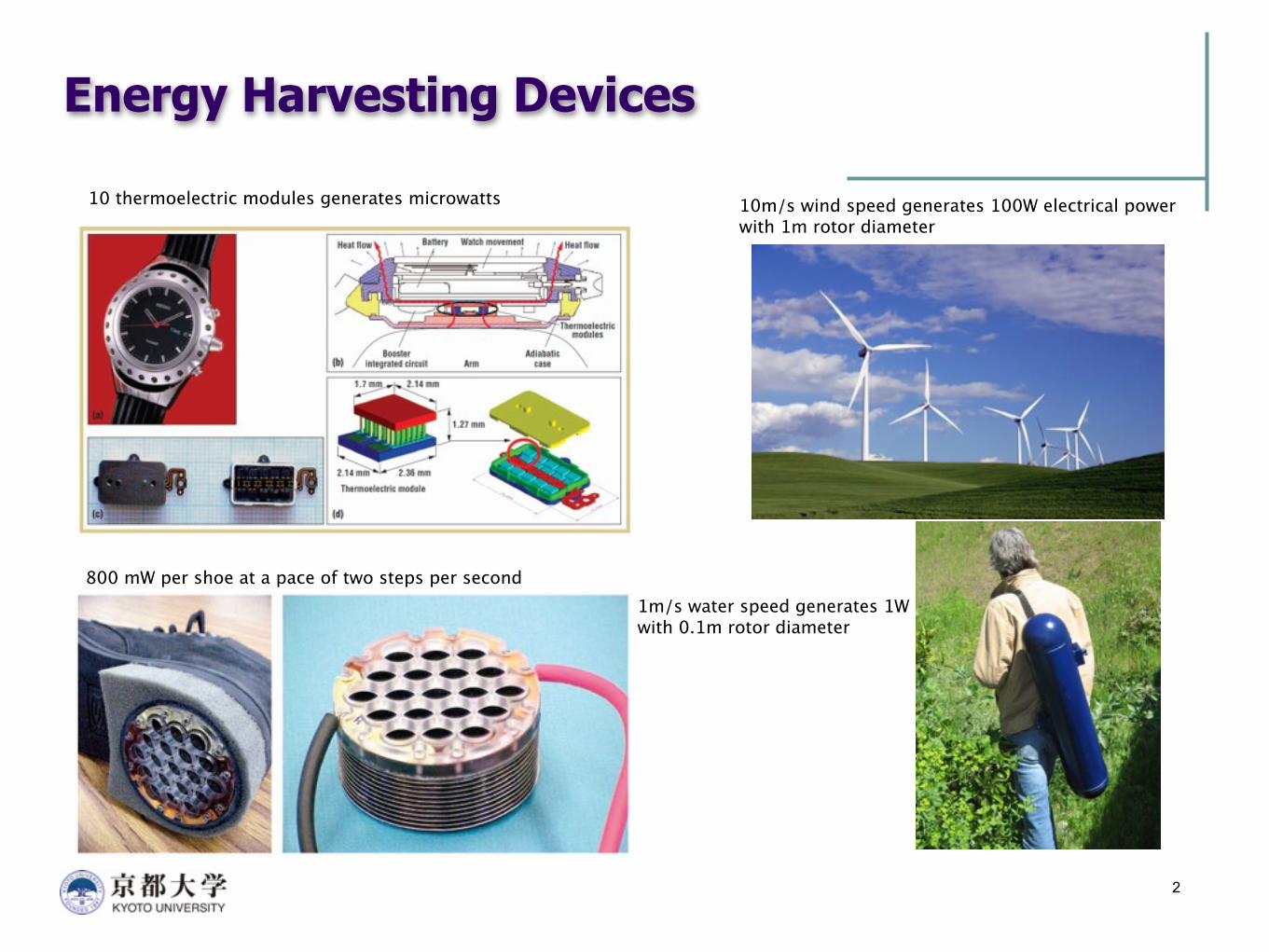
Energy Harvesting Devices
2
10 thermoelectric modules generates microwatts
800 mW per shoe at a pace of two steps per second
10m/s wind speed generates 100W electrical powerwith 1m rotor diameter
1m/s water speed generates 1Wwith 0.1m rotor diameter
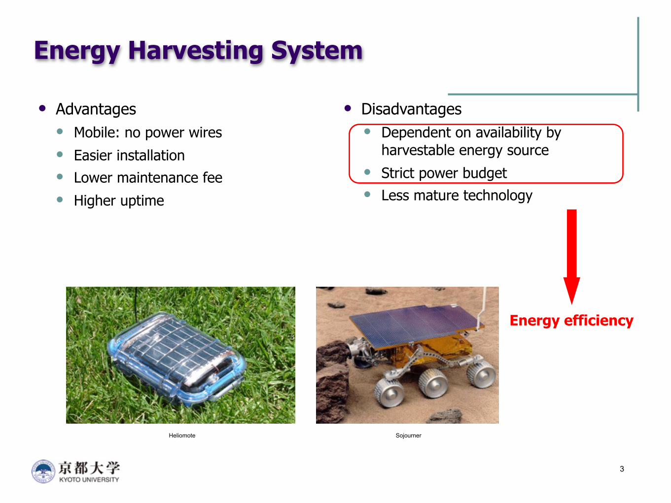
Energy Harvesting System
Advantages Mobile: no power wires Easier installation Lower maintenance fee Higher uptime
3
Disadvantages Dependent on availability by
harvestable energy source Strict power budget Less mature technology
Energy efficiency
Heliomote Sojourner
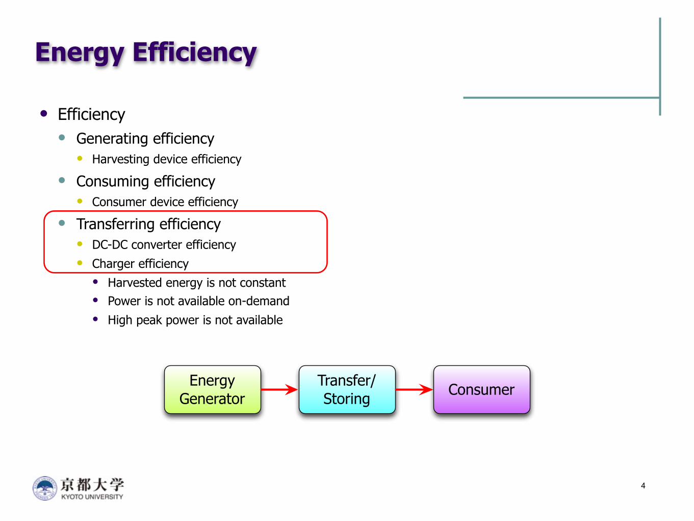
Energy Efficiency
Efficiency Generating efficiency
Harvesting device efficiency
Consuming efficiency Consumer device efficiency
Transferring efficiency DC-DC converter efficiency Charger efficiency• Harvested energy is not constant• Power is not available on-demand• High peak power is not available
4
Energy Generator
Transfer/Storing Consumer
Outline
Background Maximum power point tracking DC-DC converting power loss
Motivations Reduce the voltage difference I/O aware task scheduling
Design approach Experimental results Conclusion
5
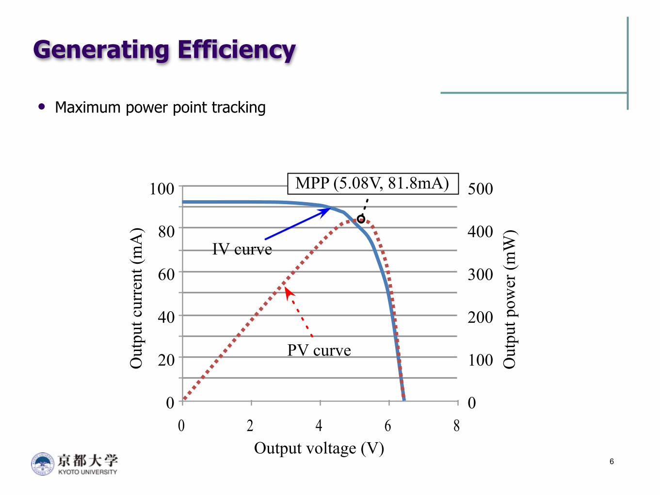
Generating Efficiency
Maximum power point tracking
6
0 2 4 6 8Output voltage (V)
Out
put c
urre
nt (m
A)
IV curve
PV curve
Out
put p
ower
(mW
)400
0
100
200
300
500
80
0
20
40
60
100 MPP (5.08V, 81.8mA)
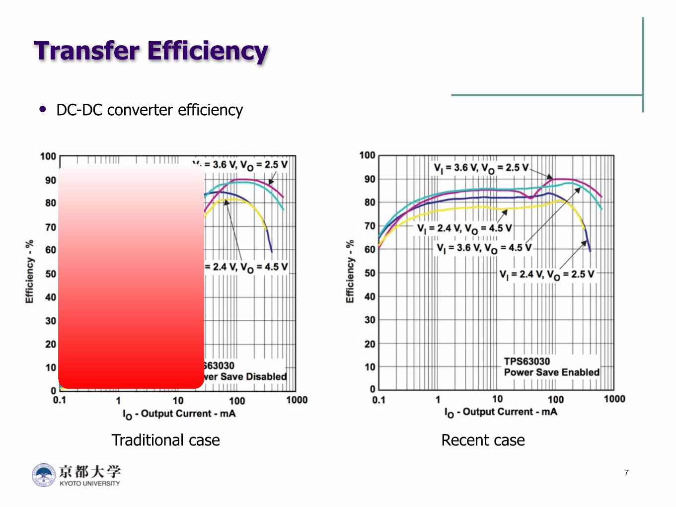
Transfer Efficiency
DC-DC converter efficiency
7
Traditional case Recent case
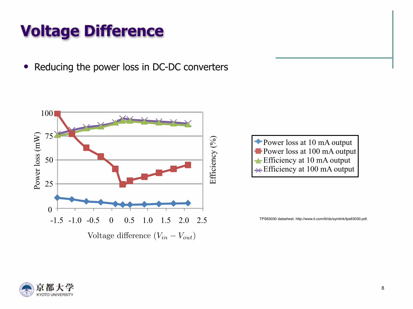
Voltage Difference
Reducing the power loss in DC-DC converters
8
Pow
er lo
ss (m
W)
Voltage di↵erence (Vin
� Vout
)
0
25
50
75
100
-1.5 -1.0 -0.5 0 0.5 1.0 1.5 2.0 2.5Ef
ficie
ncy
(%)
100
75
50
25
0
Power loss at 10 mA outputPower loss at 100 mA outputEfficiency at 10 mA outputEfficiency at 100 mA output
TPS63030 datasheet. http://www.ti.com/lit/ds/symlink/tps63030.pdf.
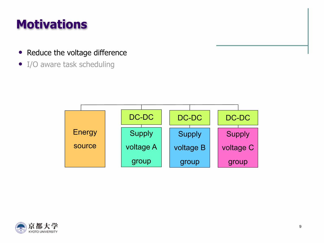
Motivations
Reduce the voltage difference I/O aware task scheduling
9
Energy
source
DC-DC
Supply
voltage A
group
DC-DC
Supply
voltage B
group
DC-DC
Supply
voltage C
group

Reconfigurable Array
10
An example for a configurable array 3 configurations with 4 photovoltaic (PV) cells Each cell has 0.5V, 80mA output Should be balanced because the size of each cell is same in this example
(4,1): 0.5V, 320mA output (2,2): 1V, 160mA output (1,4): 2V, 80mA output
Reduce the difference between
the input and output voltage
in a DC-DC converter
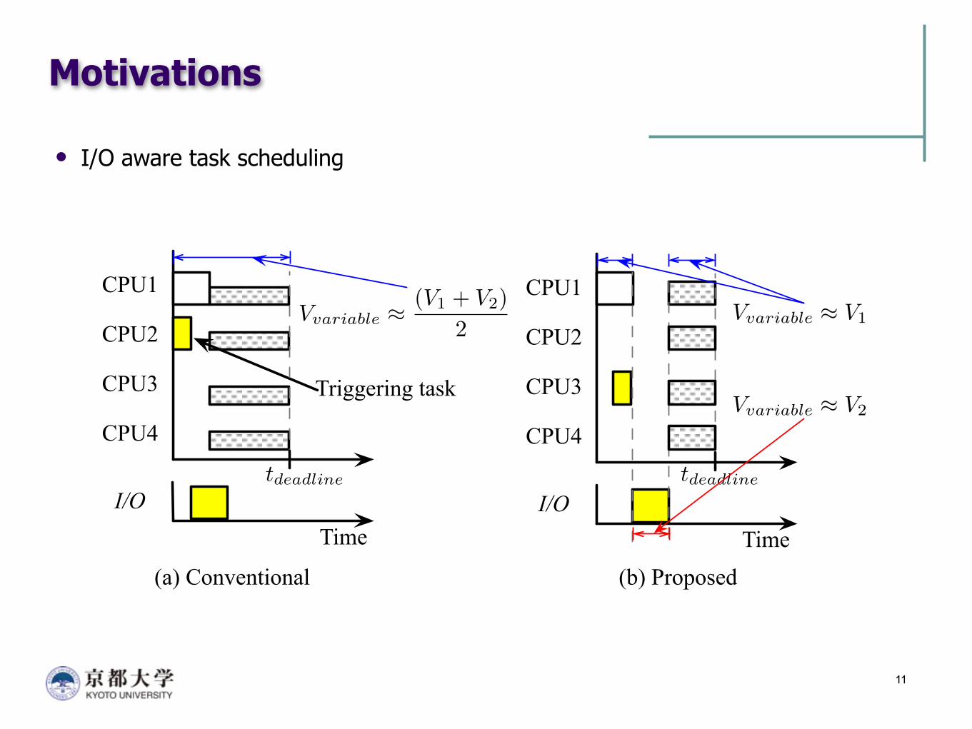
Motivations
I/O aware task scheduling
11
(a) Conventional (b) Proposed
Time
CPU1
CPU2
CPU3
CPU4
Triggering task
I/O
Time
CPU1
CPU2
CPU3
CPU4
I/O
Vvariable ⇡ V1
Vvariable ⇡ V2
Vvariable ⇡(V1 + V2)
2
tdeadline tdeadline
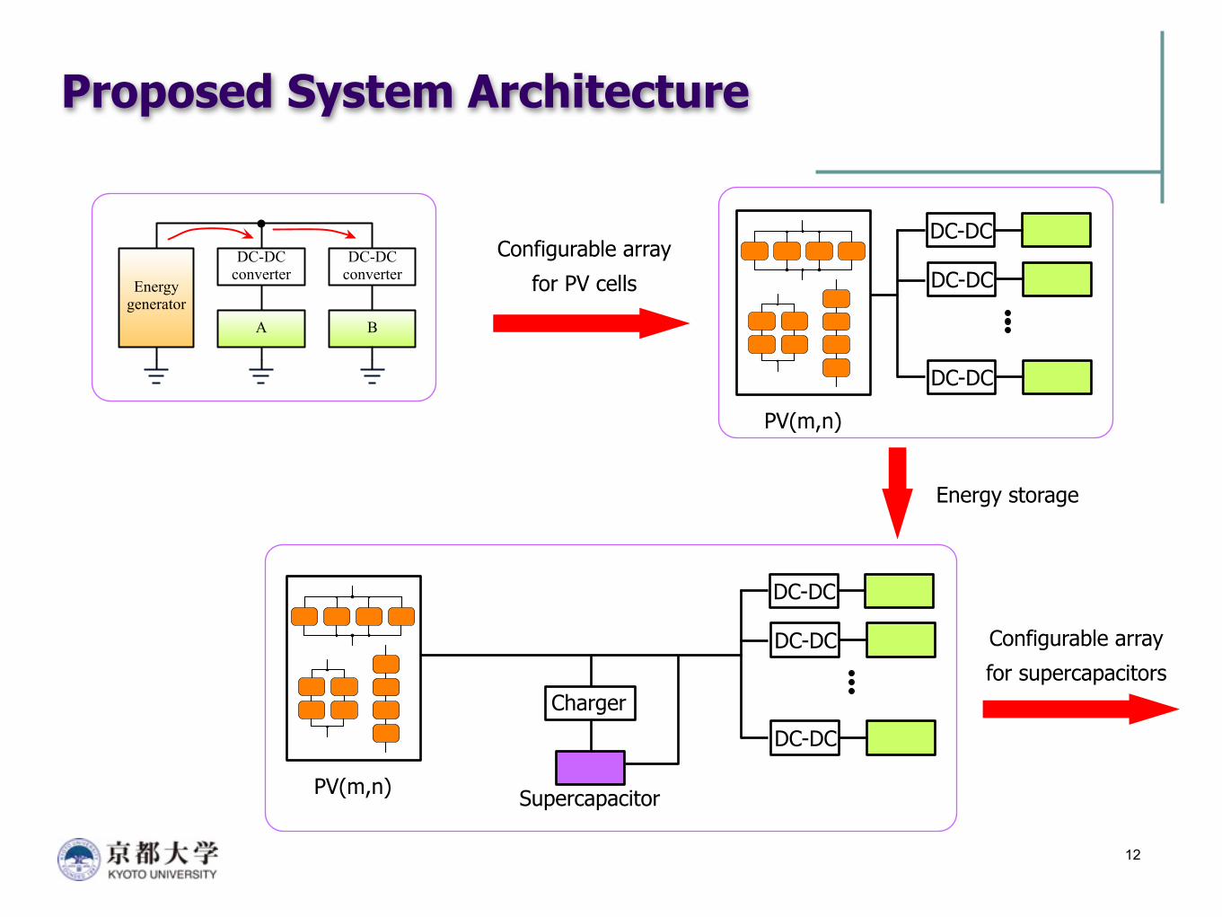
Proposed System Architecture
12
Configurable array
for PV cells
Energy storage
Configurable array
for supercapacitors
DC-DC converter
DC-DC converter
A B
Energygenerator
PV(m,n)
DC-DC
DC-DC
DC-DC
PV(m,n)
DC-DC
DC-DC
DC-DC
Supercapacitor
Charger
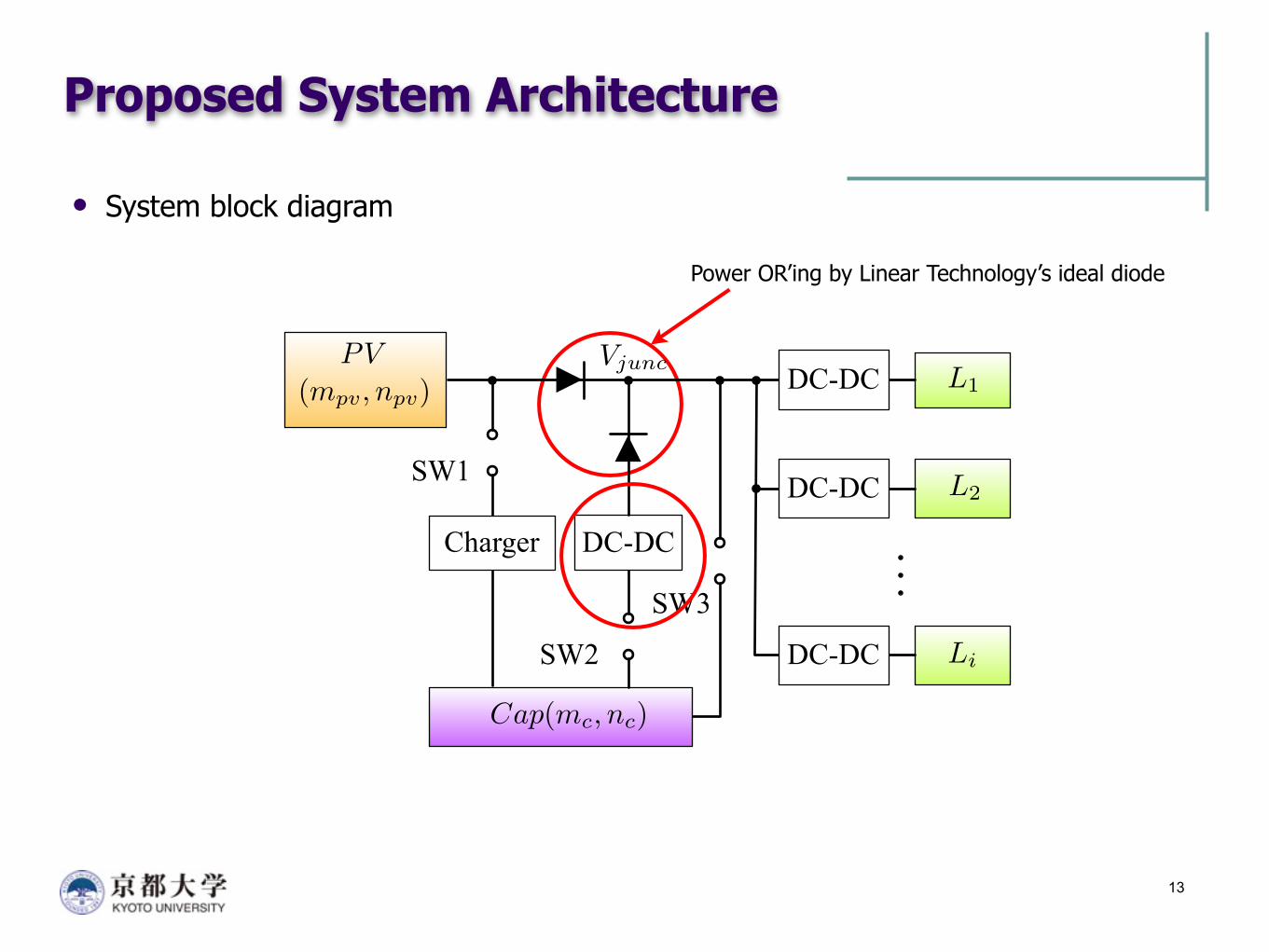
Proposed System Architecture
System block diagram
13
Power OR’ing by Linear Technology’s ideal diode
DC-DC
DC-DC
DC-DC
DC-DC
Charger
L1
L2
Li
(mpv, npv)PV
Cap(mc, nc)
SW1
SW2
SW3
Vjunc
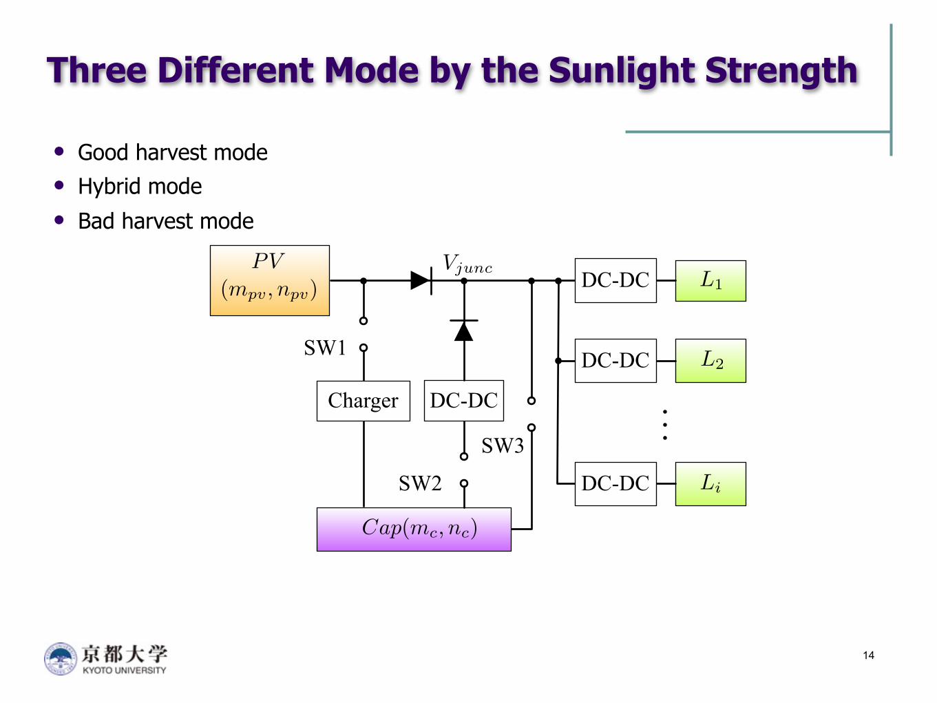
Three Different Mode by the Sunlight Strength
Good harvest mode Hybrid mode Bad harvest mode
14
DC-DC
DC-DC
DC-DC
DC-DC
Charger
L1
L2
Li
(mpv, npv)PV
Cap(mc, nc)
SW1
SW2
SW3
Vjunc
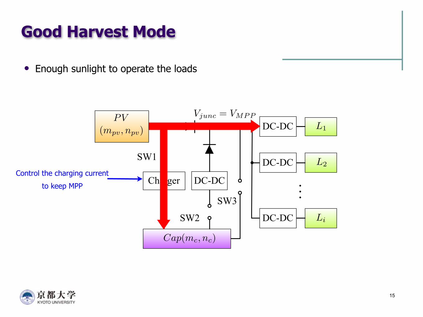
Good Harvest Mode
Enough sunlight to operate the loads
15
DC-DC
DC-DC
DC-DC
DC-DC
Charger
L1
L2
Li
(mpv, npv)PV
Cap(mc, nc)
SW1
SW2
SW3
Vjunc = VMPP
Control the charging current
to keep MPP
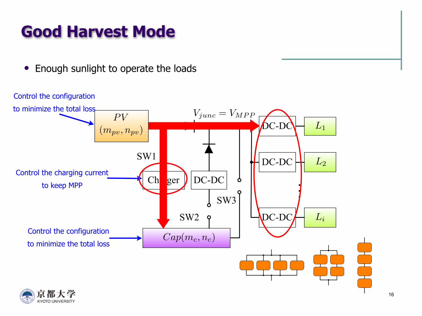
Good Harvest Mode
Enough sunlight to operate the loads
16
DC-DC
DC-DC
DC-DC
DC-DC
Charger
L1
L2
Li
(mpv, npv)PV
Cap(mc, nc)
SW1
SW2
SW3
Vjunc = VMPP
Control the charging current
to keep MPP
Control the configuration
to minimize the total loss
Control the configuration
to minimize the total loss
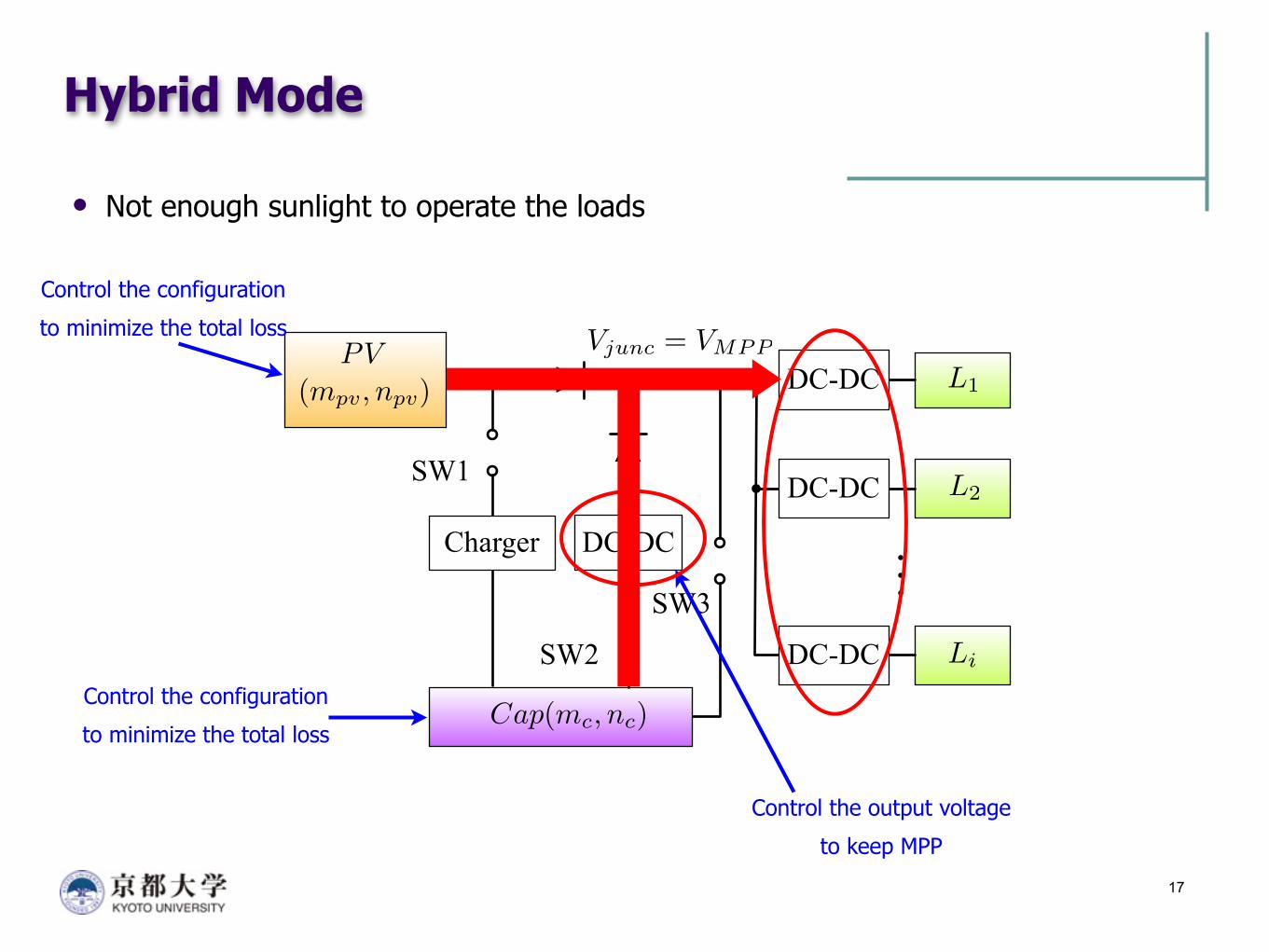
Hybrid Mode
Not enough sunlight to operate the loads
17
DC-DC
DC-DC
DC-DC
DC-DC
Charger
L1
L2
Li
(mpv, npv)PV
Cap(mc, nc)
SW1
SW2
SW3
Vjunc = VMPP
Control the output voltage
to keep MPP
Control the configuration
to minimize the total loss
Control the configuration
to minimize the total loss
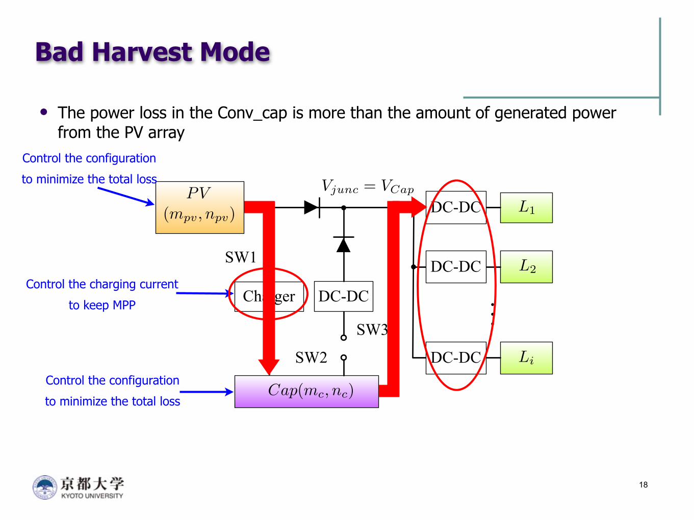
Bad Harvest Mode
The power loss in the Conv_cap is more than the amount of generated power from the PV array
18
DC-DC
DC-DC
DC-DC
DC-DC
Charger
L1
L2
Li
(mpv, npv)PV
Cap(mc, nc)
SW1
SW2
SW3
Vjunc = VCap
Control the configuration
to minimize the total loss
Control the configuration
to minimize the total loss
Control the charging current
to keep MPP
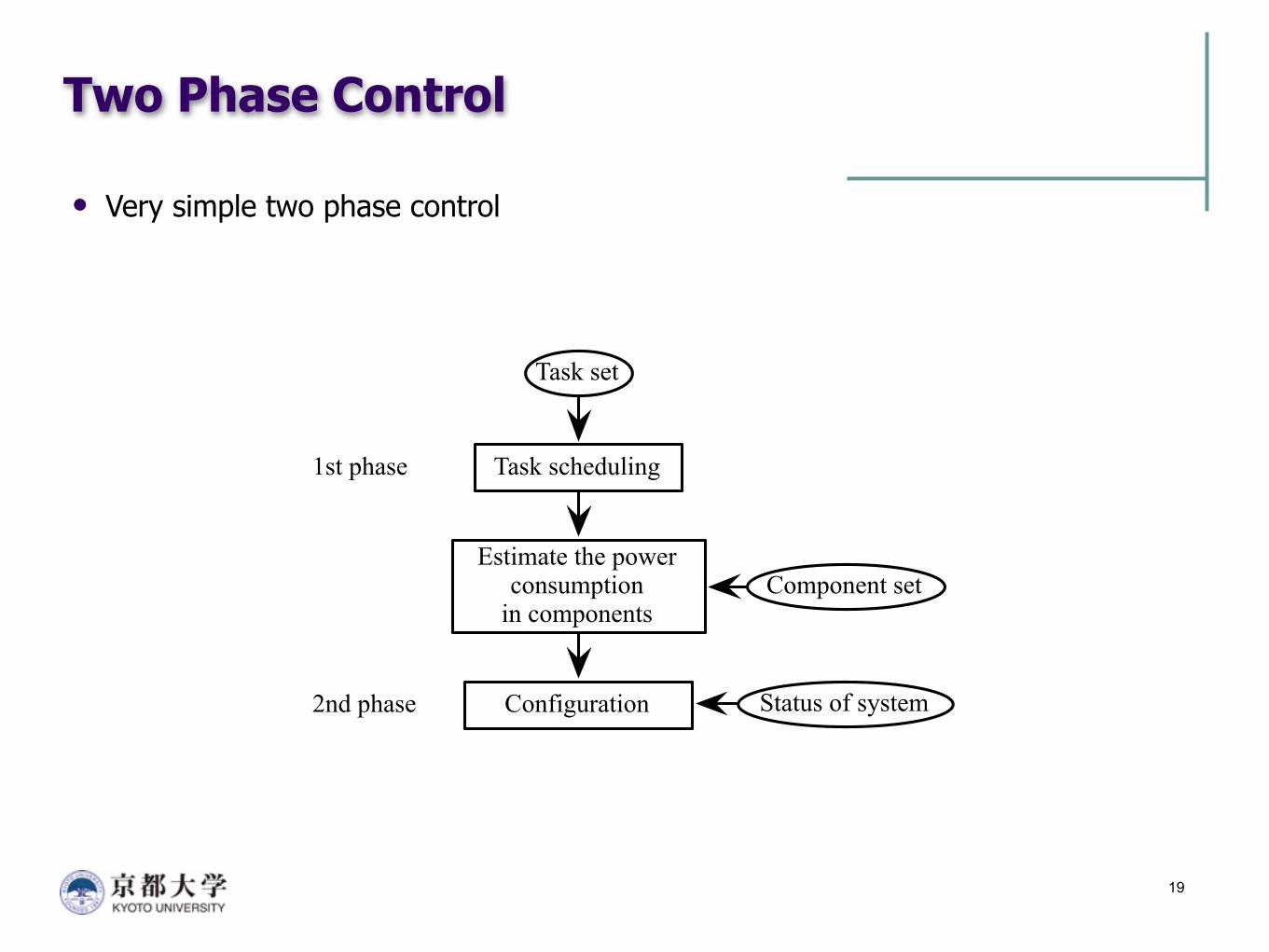
Two Phase Control
Very simple two phase control
19
Task scheduling
Task set
Configuration
Component set
Status of system
Estimate the power consumption
in components
1st phase
2nd phase
Pow
er lo
ss (m
W)
(1,6
,1,1
2)
0
30
60
90
Configuration (mc, nc,mpv, npv)
(2,3
,1,1
2)(3
,2,1
,12)
(6,1
,1,1
2)(1
,6,2
,6)
(2,3
,2,6
)(3
,2,2
,6)
(6,1
,2,6
)(1
,6,3
,4)
(2,3
,3,4
)(3
,2,3
,4)
(6,1
,3,4
)(1
,6,6
,2)
(2,3
,6,2
)(3
,2,6
,2)
(6,1
,6,2
)
120
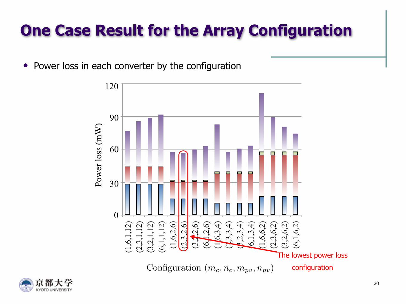
One Case Result for the Array Configuration
Power loss in each converter by the configuration
20
The lowest power loss
configuration
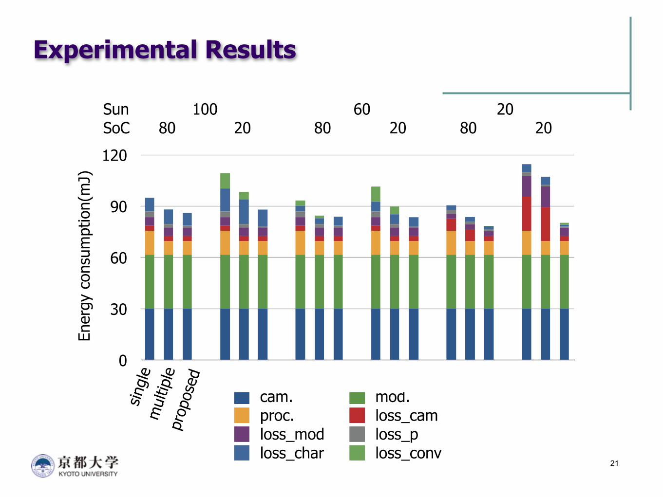
Experimental Results
21
0
30
60
90
120
single single single Untitled 1 Untitled 5 Untitled 9cam. mod.proc. loss_camloss_mod loss_ploss_char loss_conv
Ener
gy c
onsu
mpt
ion(
mJ)
sing
lem
ultip
lepr
opos
ed
Sun 100 60 20SoC 80 20 80 20 80 20

0%
20%
40%
60%
80%
single proposed multi single proposed multi
Total reduction Converter loss reduction
Experimental Results
Normalized reduction of the energy consumption Compared with the single core system
22
mul
tiple
prop
osed
Conclusion
We suggest Array configuration and I/O aware task scheduling
To reduce the voltage difference between input and output of the DC-DC converters Considering the multiple supply voltage loads
Three power path control method By the sunlight strength
Our proposed technique will reduce The system cost by increasing the energy efficiency of the system Without increasing a PV array or an energy storage
23

Thank you
25
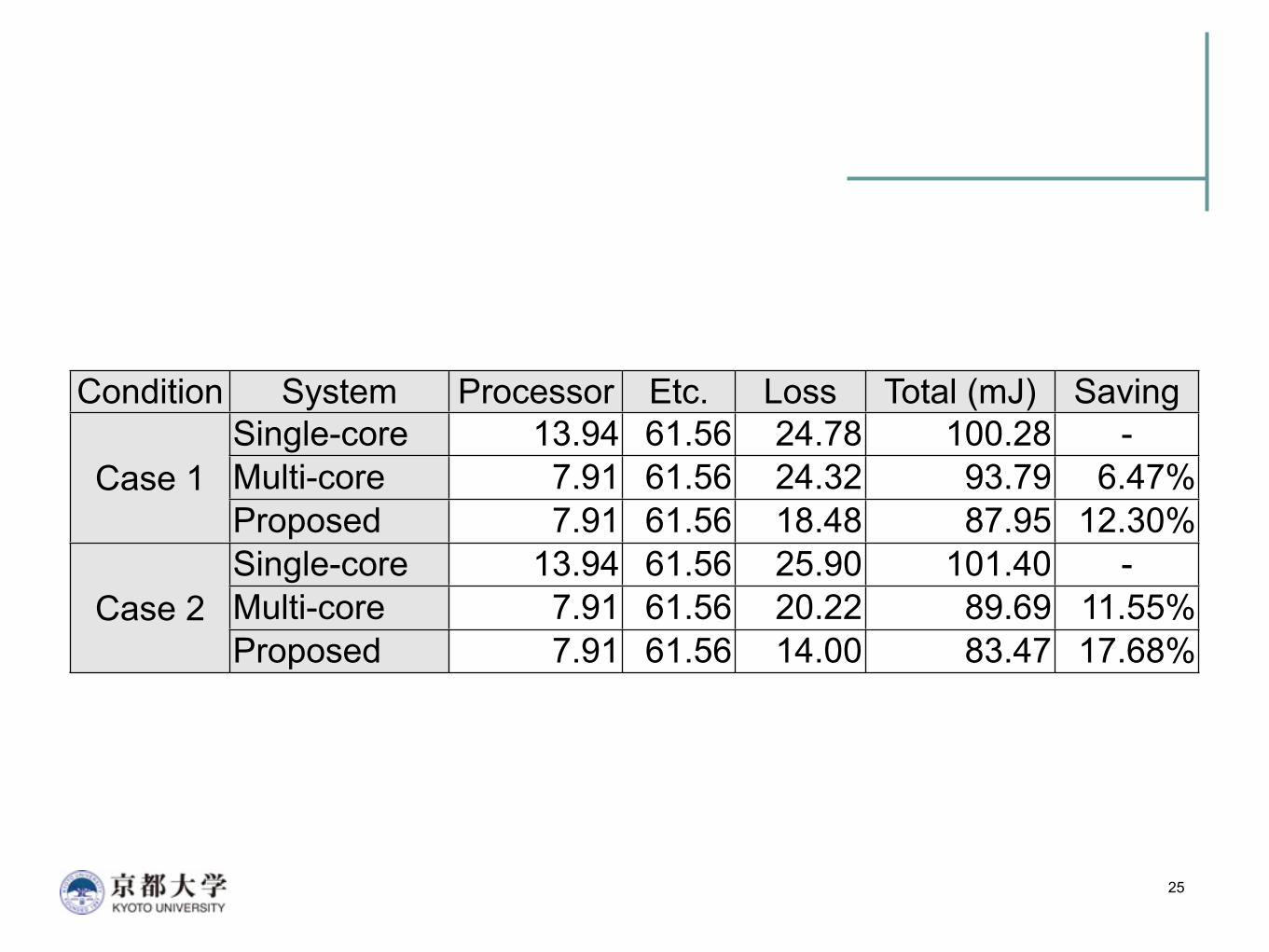
Condition System Processor Etc. Loss Total (mJ) Saving
Case 1Single-core
Case 1 Multi-coreCase 1Proposed
Case 2Single-core
Case 2 Multi-coreCase 2Proposed
13.94 61.56 24.78 100.28 -7.91 61.56 24.32 93.79 6.47%7.91 61.56 18.48 87.95 12.30%
13.94 61.56 25.90 101.40 -7.91 61.56 20.22 89.69 11.55%7.91 61.56 14.00 83.47 17.68%
26