motivair iom rev1.0 disclaimer caution ... update and or change product specifications and...
TRANSCRIPT

Engineered cooling solutions for all applications
Email:
Website:
Website:
Motivair TM
www.chilleddoor.com
www.motivaircorp.com
INSTALLATION <> OPERATION <> MAINTENANCE GUIDE
ChilledDoor® Rack Cooling System
Models: MCD‐M4 thru M16
Motivair Corporation85 Woodridge Drive Amherst, NY 14228 716‐691‐9222 (Ph) 716‐691‐9229 (fax)

The following notices and statements are used in this document:
Note: These notices provide important tips, guidance, or advice.
CD IOM Rev1.0
Disclaimer
CAUTION: These statements indicate situations that can be potentially
hazardous to you. A caution statement is placed just before the description of a
potentially damaging procedure, step, or situation.
Read this page before proceeding
This document may be updated without notice at any time. Motivair reserves the right to
update and or change product specifications and performance without notice as design
improvements occur. Please contact the factory to ensure that your version is the most up to
date.
ABOUT THIS DOCUMENT
ChilledDoor®
Important Caution and Danger Warnings in this Document
Important: These notices provide information or advice that might help you avoid inconveniences
or problem situations.
Attention: These notices indicate potential damage to programs, devices, or data. An attention
notice is placed just before the instruction or situation in which damage could occur.
DANGER: These statements indicate situations that can be potentially lethal or
extremely hazardous to you. A danger statement is placed just before the
description of a potentially hazardous procedure, step, or situation.
Product Standards and ComplianceAll products conform to industry standards and ratings; contact Motivair for a complete list
and certificates for specific models.
The manufacturer shall not be liable for any damages resulting from misapplication or misuse
of its products.
ATTENTION
Page 2
Section 1 SAFETY INSTRUCTIONS
General Safety 5
Owner's Responsibility 5
Installation / Handling 5
Application 5
Electrical Warning 5
Section 2 GENERAL DESCRIPTION
General Product Description 6
Technical Data 6
Section 3 TECHNICAL DATAElectrical Data 7
Design Capacities 7
Dimensional Drawings 8
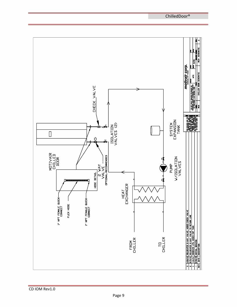
P&ID 9Pre‐Installation Requirements 10
Section 4 INSTALLATIONReceiving and Uncrating 11‐12
Floor Preparation 13Installing a ChilledDoor® 14‐15
Connecting to Coolant Distribution System 16‐19
Cleaning and Flushing/Water Quality 20‐21Filling and Venting 21‐22
Electrical Connections 22‐25
Completing the Install 25
Managing Air Flow 26
Section 5 OPERATION
PLC Controller HMI Introduction 27
PLC Controller Parameter Navigation 28‐29Set Points and Operation 29‐36
Alarm & Warnings 36‐38
Section 6 COMMISSIONING
Initial Setup 39
Description/Sequence of Operation 39‐41
CD IOM Rev1.0
ChilledDoor®
CONTENTS
Page 3

Section 7 TROUBLESHOOTING
General 41
Non‐Alarms 42Alarms 42‐43
Section 8 MAINTENANCEScheduled Maintenance 44‐45Fan Replacement 46
Fuse / Electrical 46
Draining / Removal 47‐48
Section 9 SPARE PARTSParts List 49
Section 10 DOCUMENTS AND TABLESBMS Table 50‐52
Electrical Schematics 53‐55
Section 11 SUPPORT AND WARRANTYFactory Support Contact Info 56
Notes 57
Section 12 APPENDIX Honeywell Valve IOM A1
CD IOM Rev1.0
ChilledDoor®
Page 4

Section 1
CD IOM Rev1.0
Installation
ChilledDoor®
WARNING – This unit is powered by HIGH VOLTAGE. Serious injury or death can occur. Power
being supplied to the unit must be isolated with an electrical disconnect. Any and all
electrical connections or procedures should only be performed by a certified electrician. All
electrical work or procedures should be in accordance with local, state and national electrical
codes and regulations. NEVER make any electrical connections to this unit unless the power
supply is OFF at the power supply disconnect switch.
This equipment must be installed, maintained and operated by a person or persons qualified
for this equipment. This system contains water/air circulation equipment and electrical
components. The person most suited to perform any operations or service on this equipment
is a qualified industrial technician and or electrician with experience and qualifications to
work with water systems and electrical systems.
Owner's Responsibility
Installation and operation should always be conducted in compliance with local, state and
national codes and industry best practices. When moving or installing the unit, CAUTION
must be observed at all times to ensure the safety and well being of personnel. Follow all
local, state, and national codes for moving equipment. Only appropriate and approved
moving equipment should be used.
Operation of this equipment involves potentially lethal dangers (HIGH VOLTAGE POWER and
High water Pressures.) Therefore, ALL safety precautions and warnings described in this
manual must be precisely observed. Failure to follow these precautions and warnings can
result in severe or fatal injury
WARNING
Temperature control equipment, pump stations, and electrical devices contained in this
system presents various electrical, mechanical, sound and vibration hazards. For this reason,
operation and service procedures should only be performed by qualified, fully trained and
technically competent personnel.
This equipment contains:
• High pressure water
• Electrically energized components
• Rotating parts such as fan impellers, wheels and valves
• Sharp coil fins and metal surfaces
General Safety
SAFETY INSTRUCTIONS
Application
This unit must only be used in the application for which it was designed. Do not use this
product in any hazardous environment.
Electrical
Page 5

Section 2
CD IOM Rev1.0
The ChilledDoor® is a water‐cooled door that is mounted on the back of an IT enclosure or
any standard or OEM server rack and is used to cool the air that is heated and exhausted by
devices mounted inside. The cooling effect is accomplished by using an aluminum finned
copper coil heat exchanger, Electrically Commutated (EC) motor fans, a water supply valve
and a high powered PLC control system that is built into the door. Supply and return water
hoses (available separately) deliver conditioned water or glycol to the ChilledDoor® and
remove the heated water from it. A ChilledDoor® can easily be adapted for use on server
racks and IT enclosures that are mounted either at grade or on a raised floor. A ChilledDoor®
or a series of chilled doors can be used as the primary cooling system for a data center or can
be used as a retrofit solution to increase cooling capacity of an existing facility.
Heat extracted from the ChilledDoor® is transferred to a CDU heat exchanger or to the
building's own cooling loop where the heat is exchanged to the Primary Loop and removed.
Various set points and operating parameters can be monitored and controlled within the
ChilledDoor®. These can be adjusted by the operator via an integrated BMS system.
ChilledDoor® are manufactured in various configurations, heights, widths, and kW capacities
to accommodate a wide range of popular server racks . Make sure to check specific product
specifications and design criteria for each specific ChilledDoor® Consult Motivair with any
questions.
GENERAL DESCRIPTION
General Product Description
Technical Data
Technical Data such as fan curves, electrical loads and sound data for any specific
ChilledDoor® that is not included in this general manual may be obtained from the
nameplate or from the product specification or submittal. Consult Motivair with any
questions or document requests.
ChilledDoor®
Page 6

Section 3
Standard Available Power Options: 115/1/60Hz and 208‐230/1/50‐60Hz
UmmIn
‐GPMGPMPSID°F°FkWkWkWCFMLbs.Lbs.
FLA: 7 Amps MCA: 10 Amps MOP: 15 Amp
The above sample design specifications are based on average load conditions.
Capacity and performance will vary based on flow, water temps, and fluid type.
Note:
For your specific design and application, refer to your Motivair engineering selection.
CD IOM Rev1.0
Primary100% Water or Glycol %
0‐20230‐1565°
Unit Depth:
3500 ‐ 5500Approximate Shipping Weight: 500‐700
300‐450
TECHNICAL DATA
MCD‐M4‐12 Typical Design Data:
Estimated Total Fluid Pressure Drop:
42U‐48U Racks
MAX Cooling Capacity:Total power consumed at design Available Air flow
Unit Height:
Design Fluid Outlet Temp:5‐75
As Spec'd
Approximate Operating Weight:
Design Cooling Capacity:
ChilledDoor®
Design Capacities
600‐800mmUnit Width:12"‐ 16" with interface adapter
Electrical Data
Fluid Type:Design Fluid Flow:Max Fluid Flow:
Design Fluid Inlet Temp:
As Spec'd
Specifications are subject to change without notice.
75°‐ 85°
Power 230/3/60
Page 7

CD IOM Rev1.0
ChilledDoor®
Page 8
CD IOM Rev1.0
ChilledDoor®
Page 9

CD IOM Rev1.0
Caution: Do not remove and or cut any cross members or corner stanchions for the floor
opening.
ChilledDoor®
Pre‐Installation requirements of the ChilledDoor®
The ChilledDoor® requires a specific flow (gpm) and coolant supply temperature based on the
model kW size and number of Chilled Doors to be installed. The CDS (Coolant Distribution
System) provided by the customer or a Motivair CDU (Coolant Distribution Unit) must provide
adequate flow and temperatures to perform as specified.
The proper layout, pump and pipe sizing requirements are beyond the scope of this manual.
Please consult your IT room design consultant and engineer for this information and
installation requirements. Engineering documents for the ChilledDoor® specifying flow and
temperature requirements for the model and size are available from Motivair application and
engineering upon request.
The CDS should be installed, tested and ready to accept the 1” supply and return hose
connection and any accessories within the specified hose lengths provided with the
ChilledDoor®.
The Installation of the ChilledDoor® on a raised floor requires a planned layout of each server
rack to accommodate the opening in a floor tile for the passing through and the 90° door
swing of the supply and return hoses to the coil connection and the wiring raceway to the
various accessories i.e. valve and temperature probes.
Non raised floor (Bottom Feed) installations vary greatly and require special 90° coil
connection fittings and under server rack space to accommodate the hoses and movement
please contact Motivair with your specific installation requirements. Top feed overhead
piping models are also available.
The opening cutout in the raised floor tile is located on the hinged side of each ChilledDoor®
and is approximately 6”x 8”, most of which is located inside the interface frame of the
ChilledDoor®. The floor opening should be kept as small as possible and not interfere or
obstruct the free movement of the door or hoses. The floor opening should be made in only
one floor tile and must not compromise the structural integrity of the raised floor support
system. It is a good practice to position the server racks to cut the corner edge of one floor
tile to provide the opening; this is not always possible with varying rack widths and existing
layouts.
NOTE: It is recommended that the hose cut‐out in the raised floor tile should be on the tile edge so
that the tile can be removed without having to disconnect the supply and return hoses. Should this
not be an available option, then the hose cut out will need to be made in the interior of the tile. If the
hose cut out is in the middle of the tile, make sure the hoses are run through the hose cut out before
mounting the ChilledDoor®.
Page 10

Section 4
Do not disassemble or destroy the crate they are returnable!
PREVENT BREAKAGE ‐ NEVER STORE OR LEAVE KEY IN DOOR LATCH
CD IOM Rev1.0
ChilledDoor®
INSTALLATION
10. Repeat as necessary until all doors and frames are removed and separated for
installation.
9. Return all packaging materials and boards to the crate and replace cover for return to
Motivair.
7. The door will need to be separated from the interface frame for installation. Locate the
door latch key unlock and swing open the latch. Carefully, with a minimum of 4 people on all
4 sides of the assembly raise and swing the door open from the interface frame to 90°. Then
move the door toward the top of the interface frame off the hinge pins. Lift and place coil
side down on the foam covered boards. Do not place on side, ends, or the fan side of the
door.
The chilled doors are individually shipped in returnable/reusable wooden crates in stacks of 1
to 3 doors. The doors are packaged in a horizontal position attached to the interface frame
and secured inside the crates with removable blocking and packing foam.
Caution: The chilled doors are heavy: use caution and enough man power to lift
and move.
6. The 2 methods of installing a chilled door are door and interface frame as one assembly
or separate the door from the frame and install separately (see 7.)
5. The ChilledDoor® are heavy and bulky, use enough manpower or material lifting
equipment to lift the ChilledDoor® from the crate.
Receiving and uncrating
4. Remove the screw fasteners from the hold down boards and other packing foam and
spacers and remove these items. Remove the lower screw fasteners from the crate sides and
lift crate off the shipping base. (see pics page 12)
3. Remove screw fasteners from the top covers and inspect the ChilledDoor® and contents
of the crate. Remove any “shipped loose” accessory i.e. hoses, valves, hardware packages,
etc.…
2. If stacked crates, remove the metal banding straps from the crates and carefully separate
the crates with a fork lift.
1. Upon receiving the chilled doors, inspect the crates for any visible damage. Report any
damage to the shipper immediately and document on the “bill of lading” (take photos if
possible) failure to do so could result in a loss of claim.
Page 11

CD IOM Rev1.0
ChilledDoor®
Remove the screws and top of crate
Remove the screws from the shipping boards and the lower sides of the crate, remove
boards and lift middle section off and set aside as shown.
PREVENT BREAKAGE ‐ NEVER STORE OR LEAVE KEY IN DOOR LATCH
Page 12

CD IOM Rev1.0
Contact Motivair if specific floor cutout opening dimensions and drawings for your
installation are required.
Caution: Reference only: actual opening will vary based on server rack model and
interface frame width.
The area directly below this opening must be free and clear of any and all
obstructions i.e. piping, valves, supports, braces, wire troughs, etc…
Floor opening cutout
Example floor cutout opening drawing
ChilledDoor®
Page 13

CD IOM Rev1.0
Make sure you have followed and completed all recommended tasks and procedures in Pre‐
Installation requirements of the ChilledDoor® section of this manual before attempting to
install a ChilledDoor®.
Chilled doors can be installed on active IT enclosures if necessary, however, it is
recommended that they be installed during a scheduled IT shut down period.
Installing the ChilledDoor® consists of the following Installation Steps:
1. Remove the existing IT enclosure’s rear door, hinges and door latch (if installed).
2. Attach the Interface Frame to the server rack.
3. Attach the ChilledDoor® to the Interface Frame.
4. Connect the supply and return hoses from the chilled water source to the ChilledDoor®.
5. Fill the ChilledDoor® with water or glycol and vent air from the system.
6. Have a qualified electrician or technician connect power to the ChilledDoor®.
Tools and Components Required for Installation
1. ChilledDoor® assembly
2. ChilledDoor® Installation Guide
3. Interface Frame
4. Air Purging hose (1/4” flare w/valve depressor)
5. Hose Assemblies (1 supply + 1 return)
6. Raised Floor Grommet
Customer supplied tools for ChilledDoor® installation:
1. Tools necessary to remove the existing IT enclosure rear door hinges and latch (See the
Enclosure Installation Manual provided by the enclosure vendor for details)
2. Tools necessary to attach the “Interface Frame” to the IT enclosure rear frame.
3. A bucket or collection device (approximately 5 gallons) to capture water that escapes as
you vent air from the ChilledDoor® while filling the system.
4. For raised floor installations, a tool to cut a free area out of the raised floor for the
supply and return hoses to pass through.
NOTE: Although the likelihood of water exposure is extremely small, you might prefer to
place some water‐absorbent material beneath the ChilledDoor® as a general practice when
performing procedures on the ChilledDoor®.
ChilledDoor®
Installing a ChilledDoor®
Page 14

CD IOM Rev1.0
2. The Motivair ChilledDoor® interface frames have been custom designed and built to fit
and attach to your specified server rack with your order. The existing threaded bolt holes will
be used to attach the interface frame to the rack without drilling or modification (in most
cases).
3. Locate the hardware package and the top splice plate (if provided) and attach to the top
of the interface frame. Not all models use a top plate.
ChilledDoor®
4. The server rack should be level and square and all adjustable leveling legs should be set
to the floor and locked.
5. Lift and place the Interface frame against the server rack hanging from the splice plate.
Locate and line up the pre‐drilled screw holes in the interface frame with the existing
threaded hole in your server rack and insert the screws hand tight until all are in place. Insert
the screws and nuts in the top splice plate (if used). Check for square and tighten all
mounting fasteners.
6. Raise floor installations check the position of the server rack with the Interface frame
installed for proper alignment over floor opening for the hoses. The floor opening should be
cut out per the instruction in Pre‐Installation requirements section of this manual. If not it
will need to be cut out before installing the door on the Interface frame. (Not applicable to
top feed door installations)
Attaching the ChilledDoor® to the Interface Frame
Installation Procedures
Attaching the Interface Frame to the IT Server rack.
1. To install the door on the interface frame hinge, the door must be in a 90° open position
before lifting onto the hinges.
1. The IT server rack rear doors and hinges and any rack ties should have been removed per
the rack manufacturer's IOM. If not remove them now.
Caution: Do not use coil guard for lifting. Do not touch coil while installing ChilledDoor®
as it may cause permanent damage to the coil.
2. Carefully lift the door from the horizontal position with a minimum of 4 people and
move to the hinge side of the server rack interface frame. Stand the door upright and align
the door hinge with the interface hinges as close as possible. Lift the door up from the
bottom and sides and align hinge pins and lower onto all three pins. (Hint: Three people
should lift and a forth should visually direct the alignment position).
Page 15

CD IOM Rev1.0
Caution: The chilled doors are heavy: use proper lifting methods and enough man
power to lift and move. It is recommended that three (3) or more people perform
the work required to mount a ChilledDoor® to the Interface Frame. This will
prevent damage to the ChilledDoor®.
NOTE: There is a locking safety mechanism on the female
collar. Rotate the female collar until the locking pin lines up
with its designated groove in the collar. Only when the pin
and its groove channel are aligned will the collar be able to
move down enough to allow the mating of the two
connectors
7. Insert the female supply hose coupling. Press upward until the female collar moves
upward and locks in place. Twist the female collar 180° to engage the safety locking
mechanism.
6. Locate the supply and return hoses and feed them either down through the floor
opening or if already connected to a CDS (coolant distribution system) under the floor feed
them up to the coil plug fittings Insert the female supply and return hose quick connectors
one at a time into the male plug connections that are installed on the ChilledDoor® coil
header. Make sure that the male connections are lined up for an easier connection. Slide the
collar on the female quick connect down to allow the male hose connection to enter.
NOTE: From the door open position the header connection closest to you (return grill side air
inlet to the coil) is the return hose connection and the back connection (door fan air outlet
side) is the supply hose connection.
3. The ChilledDoor® should swing freely on its hinges and close into the interface frame
without obstruction. Check for plumb and square on interface frame/rack.
4. Close the door and recheck for a good square fit into the interface frame and close the
latch to check alignment with the latch catch plates at the top and bottom of the door.
Adjust the latch catch plates on their slide brackets as necessary for a smooth latching action
and closed door positioning, tighten latch plates locking screws.
5. Locate the 2 male (plug) brass quick connect fittings installed on the ChilledDoor® coil
header pipes at the lower hinge side of the door over the floor cutout area. Note: For top
feed models these will be located at the top of the door on the hinge side.
ChilledDoor®
Page 16

ChilledDoor® field installed components:
d. The valve wiring is routed along the hoses to the attached Molex plug.
e. The 1" check valve is to be installed in the return piping at the header.
2. ChilledDoor® coil return water probe
CD IOM Rev1.0
Connecting the Coolant Distribution System to a ChilledDoor®.
Note: The floor opening should be trimmed with a suitable edge grommet and brushes (if
necessary) consult your raised floor contractor for assistance in cutting methods and trim
accessories.
ChilledDoor®
8. Carefully test the swing of the door by closing from a 90° position to fully closed position
while observing the hose and fitting clearance of the floor opening. If any resistance or
obstruction is observed or felt STOP! and remove it. The hoses must move freely without any
resistance or obstruction and should not come in contact with either edge of the floor cut out
through its entire 0°‐ 90° swing. A grommet must be used to cover any sharp edges in the
floor opening
The ChilledDoor® Coolant Distribution System (CDS) consists of a supply and return header
piping system under the raised floor or located elsewhere in a non‐ raised floor installation.
(Reference the Pre‐Installation requirements of the ChilledDoor®) The CDS can vary greatly
depending on the design and source. The CDS must have a 1” supply and a 1” return branch
connection available for each ChilledDoor® for the hose connections and other components.
The components to be installed at the CDS branch connections will vary depending on
installation requirements and options selected.
If installing your ChilledDoor® to a Motivair preassembled “Header Assembly” see “Header
Installation” section of this manual.
The following is a list of components that will need to be field installed on the Coolant
Distribution System if supplied.
1. Honeywell valve installation.a. The Motivair supply chilled water control valve is a 1” NPT 2 way cartridge type
valve (see the Honeywell valve installation manual for complete details in
appendix).b. The valve is field installed in the chilled water supply piping to the coil normally
at the inlet of the 1” supply hose at the customers supply piping feeding the coil
under the raised floor.c. The valve should be installed following standard piping practices and local plumbing codes, an inlet strainer is recommended.
The return water temperature probe is to be installed on the return piping and should be
securely attached to a clean straight section of the return piping and insulated. ("W"
labeled probe)
Page 17

ChilledDoor® field installed components: (cont…)
CD IOM Rev1.0
3. Room temperature probe (optional) routing and location.
ChilledDoor®
a. A flow meter (Customer supplied) is recommended in the main chilled water
supply piping to the chilled doors to insure adequate flow to all chilled doors and
accurate gpm and balancing values. An inline digital flow meter is a good option
for this application
Following the installation of all required and optional components on the ChilledDoor®, and
connecting the supply and return hoses to the Coolant Distribution System and ChilledDoor®.
Then pressurize and test all field piping and connections for leaks with air or nitrogen (50psi
Max) before filling and venting of the system. Only when the system pressure testing is
complete and leak free should you continue to the filling and venting section.
a. The room or server rack entering air temperature probe
(supplied) should be located in the general area of the server
rack entering air or any location that will sense the room
ambient temp. The probe may be routed out the top or
bottom raceways from the customer connection terminal
strip to your selected location. ("R" labeled probe) Connect to
the appropriate terminals (see wiring/connections diagram in
appendix).
4. Leak detection (WDS) sensor installation.
5. Flow‐meter (optional) installation.
a. The leak detection sensor tape and wiring
must be field located under the raised floor below
the door at the low point around the piping and
hoses and may be secured to the floor using a
suitable non‐conductive adhesive (Silicone). The
Motivair supplied sensor kit includes 10’ of sensor
tape
Note: The installation and use of the room probe is not mandatory and the function can be
switched off. However this will also turn off high and low room temperature monitoring
Page 18

CD IOM Rev1.0
c. Field connect the 2 way control valves and install return water temperature
probes per paragraph #2 above.
Note: Distribution headers are available in 6 to 16 ports assemblies and come in a variety of
connection options to facilitate most distribution applications. These pre‐assembled headers
mounted on a drip pan complete with all necessary components and quick connections make
installations quick and easy. Please contact your ChilledDoor® representative for
configurations and details.
16 Port Distribution Header
6. Header distribution assembly (optional) installation.
ChilledDoor®
a. An optional Motivair supplied distribution header assembly is installed under
the raised floor and should be centrally located in close enough proximity to the
chilled doors being connected for the chilled door supply and return hoses to
connect to the header assembly without being stretched or stressed. (Hoses can be
ordered and supplied in varying lengths please consult your Motivair
representative).
b. The header assembly consists of a pre‐piped manifold with the 2 way control
valves and stop valves in place. The supplied hoses must be field connected (Quick
Connect) to the header assembly (see hose installation section of this manual).
Page 19

CD IOM Rev1.0
Minimum Water Quality standard for Motivair ChilledDoor
Good installation practice must include Initial system flushing
Motivair Water Quality
Total Water Hardness
7.3‐8.3softened water should be used
MineralChlorideCalcium
A water treatment professional should be consulted regarding the testing and proper
chemical treatment for a closed loop system’s composition and fluid requirements. Proper
levels of all loop and makeup water must be maintained per industry standards and best
practices. Proper levels of pH, Alkalinity, Chlorides, Nitrite, and Conductivity, along with other
chemicals and metals in the system must be tested for and monitored. A treatment program
should be implemented at the time of initial system commissioning to provide long term
system reliability. This testing is outside this documents scope.
Water testing and filtration must employed to ensure a system is filtered to <50 microns
(High limit of a closed loop system per industry standards) The recommendation by Motivair
is to utilize a 5 micron or less bag/cartage type filter in the closed loop or other suitable
method of removing suspended solids to a minimum 5 microns or less. Iron levels less than
<2.0 ppm ‐ Copper levels less than <0.1 ppm ‐ Suspended solids <1 mg/L.
Cleaning and Flushing
Magnesium
Sulfate
Recommended Limit < 25 ppm< 15 ppm< 15 ppm
<30 ppm< 25 ppm
Cleaning and flushing of any field installed piping that may be required must be completed
before connecting to any Motivair equipment. Motivair supplied ChilledDoor®, CDU's,
Underfloor Distribution Headers, and all hoses are shipped clean and new, these require no
cleaning or flushing.
The following table is a guide
for initial fill water for all
closed loop system using
Motivair Chilled Doors and
components. Potable water is
a good source and starting
point for initial filling.
To insure long term reliability and operation of the sealing components of the Motivair
Chilled doors and coolant loop distribution components clean water with a low to no
suspended solids level is required for closed loop systems. Suspended
Particles can damage O‐rings, mechanical pump seals and cartridge valve seals and operation.
Excessive suspended solids will leave deposits in system piping, including critical sealing and
heat transfer surfaces. The following recommendations are a minimum for and closed loop
distribution system utilizing the Motivair Chilled door, CDU or header distribution system.
pH
ChilledDoor® Filling and Venting Procedure
ChilledDoor®
Page 20

Fill and Vent Sequence
To fill the ChilledDoor® with water for the first time, complete the following step:
CD IOM Rev1.0
Water Quality
The fill point of the closed loop Coolant Distribution System will vary depending on your
particular layout and components, but most systems provide a hose bib valve connection
point to connect to for filling. If using a special mixture, a transfer pump will be necessary to
fill the system. During filling and venting, the system pressure will need to be constantly
monitored and maintained to provide pressure to purge air from the closed loop while also
avoiding over‐pressurization of the system.
The bottom feed chilled door coil headers located on the hinge side of the door have a 1/4"
Schrader bleed valve at the top of each header to facilitate air purging from the chilled door
coils. Top feed chilled doors do not have bleed valves as they are not the high point of top
feed system layout.
1. Locate and remove the safety caps from the Schrader vents on the top of the
ChilledDoor® headers to attach a purge hose to both vent valves.
2. Place other end of the purge hose into a 5 gallon bucket to catch the water
that escapes while filling and venting the ChilledDoor®
NOTE: Air Purging hose tool available separately
from Motivair or local supply house. Use a hose of
adequate length (6ft) with a combination stop
valve attached (as shown)for better control of the
venting process.
3. Attach the other end of the long hose to both the vents, one at a time at the
top of the ChilledDoor®. As the air purging tool is screwed onto the valve, air will
begin to vent out.
The use of Propylene and Ethylene glycol mixtures and water treatment additives that are
compatible with the piping and wetted materials used in the coolant distribution system are
acceptable. A qualified water treatment contractor should be consulted for
recommendations and water analysis testing that meet your specific requirements.
Caution: always wear safety goggles or other eye protection whenever filling, draining or
venting air from the ChilledDoor®.
Warning: Do not use deionized water (DIW) in chilled door closed loop systems as
DIW is corrosive to certain metals.
ChilledDoor®
Page 21

Fill and Vent Sequence (Cont…)
CD IOM Rev1.0
7. Screw the valve caps onto the air‐purging valves and hand‐tighten them to
provide a secondary safety seal
8. Check all connection points to the ChilledDoor® and vents to ensure all
connections are tight and leak free.
10. Following the completion of the purging and air venting of all the chilled door
coils and system components circulate the water in the closed loop system and
recheck system high points for trapped air and vent.
WARNING: Risk of electric shock. Connecting the ChilledDoor® to the building
power source should be performed by a qualified technician or skilled electrical
contractor. Ensure all electrical connection points are DRY before connecting
power.
Note: Water will spray or spit into the bucket during this procedure. If air remains
in the coil it will cause a splashing or gurgling sound. Repeat the air‐purging
procedure on both valves if this sound is present.
4. Maintain pressure and flow of the system
make‐up water to the ChilledDoor®. Air that is
entrained in the water and other air from the
system will exit the ChilledDoor® via the venting
tool into the collection bucket
Electrical Connections to the ChilledDoor®
6. Feel both vertical headers of the ChilledDoor® that feed water to the coil. If
they are cold, then flow is confirmed through the ChilledDoor®.
Note: If no flow or pressure at vent: be sure all manual isolation valves are open
and the 2 way control valve is in open position.
5. When there is a constant stream of water (no air) leaving the air purging hose
into the bucket, disconnect and remove the air purging tool from the top of the
ChilledDoor®.
ChilledDoor®
Attention: If water drips from the Schrader valve (Purge Vent at the top of the
ChilledDoor®) after you remove the air‐purging hose reattach the hose and
disconnect it again to exercise and seat the seal.
11. Complete the filling process insuring the closed loop low side (pump return)
pressure is maintained in a positive pressure. A minimum of 7 psi to 15 psi is a
normal range for a low pressure closed loop system.
Page 22

CD IOM Rev1.0
Note: Make sure that all local and national electrical safety requirements and
codes are strictly adhered to during the installation process. Motivair accepts no
responsibility under any circumstance for failure to adhere to these requirements.
It is the customer’s responsibility to know, understand and comply with any and all
local electrical codes and safety rules.
The ChilledDoor® is an “Active” rear door heat exchanger that includes an array (Qty 2‐5) of
electronically commutated (EC) motor fans and an integrated PLC controller. All power for
these features is provided from the main electrical connection made to the building power
supply. A ChilledDoor® may be specified to run with 115/1/60 power, 208‐230/1/60 power or
230/1/50 power.
NOTE: Confirm that the building power being applied to the ChilledDoor® is the same as that
which the ChilledDoor® was designed for. A shipped loose, 2‐way water control valve is also a
powered device. The 24v power for the 2‐way valve and 0‐10v control wiring are supplied
from the ChilledDoor®.
Verify enough power is available before connecting power cords to any rack power
strip feeding internal servers. DO NOT OVERLOAD POWER STRIPS.
WARNING: Risk of electrical shock. Disconnect power before opening vanity
panel.
1. Check to ensure that the correct power and amperage is available to run the
ChilledDoor®. ChilledDoor® power requirements can be found on the electrical
Name tag provided.
Electrical Connections (Cont…)
2. Only a certified technician or electrical contractor should wire from the
building power to the designated power location on the ChilledDoor® terminal
strip.
3. Access to all electrical instruments (Fans, PLC, and 2‐way valve) and power
terminals is located behind the stainless steel vanity panel on the front of the
ChilledDoor®.
ChilledDoor®
CAUTION: There are moving parts inside the ChilledDoor®. Be sure to keep
hands or other appendages and any loose clothing away from the fans if they are
turning.
4. A factory installed and connected power cord(s) with C14 or C20 plugs are
prewired from the terminal strip in the ChilledDoor® to be plugged into a power
strip in the server rack or building supplied power.
Page 23

CD IOM Rev1.0
Electrical Connections (Cont…)
5. If hard wiring to a building power source remove the pre‐wired plug and
connect power wires to the designate power terminals on the customer
connection terminals inside the ChilledDoor®.
Note: There are power and control wiring conduit raceways that enter from both the top
and bottom of the ChilledDoor® that lead to the customer connection terminals inside the
ChilledDoor®. These are use for either top feed or bottom power and control feeds to the
ChilledDoor®® (shown below)
ChilledDoor®
Customer connections terminal strip
Warning: Terminal strip layout is subject to change, above example is accurate at
the time of this manual publishing for standard doors. ALWAYS reference the
schematic shipped and attached to the chilled door panel.
6. Check that all wiring connections are secure before applying power to the
ChilledDoor®
Page 24

Complete the following steps:
CD IOM Rev1.0
NOTE: Your ChilledDoor® PLC is pre‐programmed with factory software to enable
smooth operation. Many client and factory set points can be adjusted per the
ChilledDoor® Start‐up and Operation section of this manual.
2. Make sure that the supply and return hoses are free and unobstructed in the
hose cut out in the raised floor (bottom feed). Hoses should run straight down
below the raised floor to the Coolant Distribution System.
3. Close the ChilledDoor® and close latching and locking handle. Recheck the
latch rod alignment latching to the catch plates and adjust as necessary.
4. Recheck the ChilledDoor® after several hours of pump and flow operation. If
all air has not been removed from the system or ChilledDoor® during the filling and
venting procedure, you will hear a gurgling, splashing, turbulent noise. This is an
indication that air is still trapped in the ChilledDoor®. Repeat the air purging and
venting procedure. This should also be checked again in 30 days.
5. Perform visual inspection of all field installed probes and wiring for neat and
proper attachment points and to prevent snagging or pinching with door
movements.
Completing the Installation
9. Turn on power to the ChilledDoor®. Once power has been applied, the PLC
display will light up indicating that power has been connected correctly. There will
be a 30 second system diagnostic check before the PLC takes control during which
the fans will operate at full speed. After that, the ChilledDoor® is ready for
operation
6 Finish the installation with proper house‐cleaning procedures and site cleanup.
ChilledDoor®
7. Confirm that all wiring connections to valve, probes, water sensor, and all
other optional components have been made and terminated correctly. All terminal
strip connections have been factory terminated to the proper probes and water
valve harness for ease of installation.
8. Close stainless steel vanity door on the front of the ChilledDoor®. Make sure
that vanity plate lock is closed and secure.
1. Replace any raised floor tiles removed for installation and floor grommets.
Page 25
CD IOM Rev1.0
ChilledDoor®
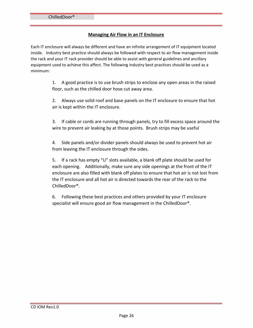
Managing Air Flow in an IT Enclosure
Each IT enclosure will always be different and have an infinite arrangement of IT equipment located
inside. Industry best practice should always be followed with respect to air flow management inside
the rack and your IT rack provider should be able to assist with general guidelines and ancillary
equipment used to achieve this affect. The following industry best practices should be used as a
minimum:
1. A good practice is to use brush strips to enclose any open areas in the raised
floor, such as the chilled door hose cut away area.
2. Always use solid roof and base panels on the IT enclosure to ensure that hot
air is kept within the IT enclosure.
3. If cable or cords are running through panels, try to fill excess space around the
wire to prevent air leaking by at those points. Brush strips may be useful
4. Side panels and/or divider panels should always be used to prevent hot air
from leaving the IT enclosure through the sides.
5. If a rack has empty “U” slots available, a blank off plate should be used for
each opening. Additionally, make sure any side openings at the front of the IT
enclosure are also filled with blank off plates to ensure that hot air is not lost from
the IT enclosure and all hot air is directed towards the rear of the rack to the
ChilledDoor®.
6. Following these best practices and others provided by your IT enclosure
specialist will ensure good air flow management in the ChilledDoor®.
Page 26

Section 5
“Alarm “ – press to view current alarm & clear alarms
“Program” – press to enter the programming menu screen
“Escape” – press to go back one screen or one space
“Down arrow” – press to scroll down or lower a setting
“Up arrow” – press to scroll up or raise a setting
CD IOM Rev1.0
The above Display is the main screen or “Home Screen”. It displays the controlled points and
the state of the PLC, i.e. "Unit off By Keyboard".
ChilledDoor®
OPERATION PLC control HMI introduction
HMI Screen Navigation
The Human Machine Interface (HMI) is a 6 button built‐in display screen The 6 button
functions on bottom as follows:
“Enter” – press to navigate to changeable parameters and confirm/save changes
The HMI screens are a scrolling menu style. The up and down arrows will scroll through all
available screens in a sub menu; i.e. press alarm and scroll through all active alarms.
Page 27

CD IOM Rev1.0
Pressing the DOWN ARROW key will
scroll to the next information screen first
is the fan RPM I/O display showing the
actual RPM reading of each fan and is
used for monitoring and alarm functions.
The next info screen shown by pressing
the DOWN ARROW key contains the
actual output % to the fans and the
chilled water valve. Also the power
source for dual power feed option
The home screen is displayed when you
press the ESC key or after a few minutes
of inactivity. The home screen displays
the temperature readings of the chilled
door. The "I" Icon for information is a
reminder to scroll down for additional
info screens.
Press the "PRG" key for access to the
programming menu. The programming
menu contains three sub menus as
shown use the UP & DOWN ARROW keys
to highlight your selection then press the
ENTER key to confirm your selection.
Pressing the ENTER key enters the
“On/Off Unit” screen as shown. Press
ENTER key to highlight “SWITCH OFF”
then press the UP or DOWN ARROW key
to change to “SWITCH ON”. Press ENTER
key to confirm your selection. The
chilled door is now ON.
HMI Screen Navigation
ChilledDoor®
Page 28

Air Outlet Temperature set point screen
CD IOM Rev1.0
The following Client setup screens are provided to allow the client/end‐user to make
adjustments and changes to the default settings if necessary to facilitate an operating
parameter or site specific condition. Set points for outlet air temp and server air outlet
temps or pressures and all alarm thresholds are available on the following screens.
On "Main Menu" (above): Highlight
“Manufacturer setup” press ENTER for
“Manufacturer Password “ screen. Press
ENTER to highlight the PW number 0000 ‐
Contact Motivair for password to this
area of the menu.
Highlight “Client Settings”. Press ENTER
for “User Password “ screen. Press
ENTER to highlight the first digit and use
the UP ARROW to enter the PW.
(Default PW=1234)
Press ENTER to move to the second digit
to insert “2‐3‐4” Press ENTER etc…
Client Settings Screen
Set Point of the air outlet temperature
and differential band: The regulation
type is also selectable between
Proportional "P" and Proportional and
Integral time "PI". This screen also
displays the current air outlet temp. This
parameter controls the CWV % opening
to maintain a constant air temperature
at varying loads.
HMI Screen Navigation (Cont…)
ChilledDoor®
Client Set Point Setup
The Client/User programming submenus contain all the Set‐point/alarm setting screens
accessed by scrolling with the UP/DOWN ARROW keys. The first screen (shown) is the air
outlet set‐point screen. Press ENTER to highlight the parameter to change and use the
UP/DOWN ARROW to change setting then press ENTER to confirm change.
Page 29

Server Outlet Temperature set point
Water Valve Min and Max set points
Fan alarm delay Min/Max set points
High and Low outlet air temp alarm set points
CD IOM Rev1.0
The high and Low air out temp alarm is a
differential setting from "Air Outlet" set
point i.e. the set point (above) of 75°F + the
° above setpt 10°F = 85°F alarm point temp
delayed 60 sec. The Low air outlet alarm
10°F below setpt ‐ 10°F = 65°F delayed 120
sec.
Set point for fan min speed and fan
alarm activation time delay. Also max fan
speed limit. These set points should not
be adjusted without a good
understanding of the effect on the
operation. Consult motivair if
adjustment is necessary.
Client Alarm Setup
Set points to limit the CW Valve opening
and closing limits. Also displays water
out temp. A Min open % may be
required to prevent dead heading of a
pump or low load may require a 0%
setting. Max limit % for balancing only if
necessary. (note: Set & Diff not used)
Client Set Point Setup (cont…)
Set Point of the server outlet air
temperature and differential band. The
regulation type "P" or "PI". Also displays
the current server air outlet temp. This
parameter controls the fans speed to
maintain a constant coil air on temp at
varying loads
ChilledDoor®
Page 30

CD IOM Rev1.0
The high and Low ROOM temp alarm is a
differential setting from "Air Outlet" set
point. The Air Out set point of 75°F + the
° above set point of 15°F = 90°F alarm
point temp, delayed 60 sec. The Low
room temp alarm of 15°F below set point
75F ‐ 15°F = 60°F alarm point, delayed 60
sec. This parameter based on the ROOM
temp probe.
Client Alarm Setup (cont…)
High & Low water temp alarm set points
Set point for alarm activation on high or
low return water temperature and
corresponding time delay
High & Low Room air temp alarm set points
Set point for alarm activation on high
server out temperature and
corresponding time delay.
High server out temp alarm set point
Water Detection alarm enable
The alarm set‐up for the Water
Detection System (WDS) must be
enabled. The “Enable WDS Valve close”
option can be set to “yes” or “No” If set
to “yes” the valve will close all chilled
water flow to the chilled door coil to
isolate and minimize any leak that may
occur between the valve and the return
check valve on a WDS alarm signal.
ChilledDoor®
Page 31

BMS set up screen
BMS set up screen
Probe Calibration settings
Date And Time input screen
CD IOM Rev1.0
ChilledDoor®
Client Misc. Setup
Client set up parameters for enabling
On/Off control by the BMS system as an
added layer of protection to prevent
accidental off signal to chilled door. Also
the ability to disable the local buzzer.
The probe calibration screens are for
adding an offset to exact a probe reading
max offset is +/‐ 9.9°F. Probes more
than 5°F out of calibration should be
replaced.
The BMS set‐up is to select your protocol
BacNet ‐ Modbus ‐ Lon based on your
selected communication option. The
Baud rate is fixed based on protocol
selected. The BMS address is for Modbus
only.
Date and time input screen is to set the
current date and time to display on the
"Home screen" and history logs. Note:
This screen is not a clock screen only a
set up page and will not display the
correct time or date.
Page 32

Daylight Savings Time setup
Alarm History log screen
Program info screen
Program info screen
CD IOM Rev1.0
Client Misc. Setup (cont…)
Enable and disable DST per your
geographic location.
Client alarm history log used to review
previous alarms with time and date
stamp. Press enter and use arrows to
scroll through logs.
Manufacturer Setup
Displays the program version along with
the PLC boot and bios versions and
dates.
The Manufacturer setup area of the menu is password protected and should only be accessed
with Motivair permission. All parameters in this section are preset per the specified
ChilledDoor® and should rarely need change.
Displays the PLC type along with the PLC
memory sizes and cycle speed for
diagnostics.
ChilledDoor®
Page 33

Fan setup enable screen
Default setup parameter screen
Default setup parameter screen
Unit Of Measure Selection screen
CDU IOM Rev1.0
Enable and disable parameter for chilled
door fan monitoring and alarm
functions. This will not stop fan's
operation only the monitoring of them.
Select unit of measure °C or °F Note:
unit must be switched off to change unit
of measure.
Parameters to set manufacturer defaults
for different chilled door control
configurations
Parameters to set manufacturer defaults
for different chilled door control
configurations
Manufacturer Setup (cont…)
ChilledDoor®
Page 34

Language Selection screen
Input/output configuration screens
Program Defaults install screen
Password Change screen
CDU IOM Rev1.0
Currently program is only available in
English ‐ language selection disabled
I/O setup parameters for all analog
inputs ‐ next 4 screens
Manufacturer Setup (cont…)
This parameter screen reboots the PLC
controller and installs all manufacturers
default settings into the memory.
ChilledDoor®
PW change screen.
Page 35

CD IOM Rev1.0
ChilledDoor®
G2 Client Set Point Setup
The Motivair G2 version is both physically larger and increased kW capacity ChilledDoor® with
the same operating principles and characteristics as the standard door but uses a slightly
different PLC and has a pressure operating function with the main HMI screen shown below.
The main screen shows the
operating pressure of the fans
in W.C." in place of the room
temp.
The pressure set point screen
shows the actual fan pressure
and the set points for the min
and max pressures and the
associated alarm time delay
All of the HMI screens for the G2 version are the same or very similar to the screens shown
on the preceding pages.
Alarms and warnings
The "ALARM" warning screen appears
when any alarm is triggered. This screen
along with a buzzer is to alert an alarm
condition is present.
Page 36

CD IOM Rev1.0
Alarms and warnings (cont…)
ChilledDoor®
Pressing the alarm key 1 time will silence
the alarm buzzer and display the current
alarm. Pressing the alarm button a
second time will acknowledge and clear
the alarm if the condition has cleared.
Following the acknowledgement of the
alarm (2nd press) the "No active alarms"
screen will appear and direct you to the
alarm history log. If the alarm condition
has not been cleared (i.e. overload not
reset) the alarm screen will re‐trigger
another alarm.
Press "Enter" while on the above screen
to enter the alarm log area. The alarm
log entry is recorded at every alarm and
will store each alarm. The log records the
alarm number sequence 001, 2, 3…,
Time, date, and the alarm description.
Alarms and warnings are to signal a problem or issue with the ChilledDoor® or an associated
system connected to the ChilledDoor®. Refer to the Troubleshooting section of this manual
for information on alarm causes and system checks
The screens shown below are a list of possible alarms generated by the ChilledDoor®.
Page 37

CD IOM Rev1.0
ChilledDoor®
Alarms and warnings (cont…)
Page 38

Section 6
Initial Setup Parameters:
CD IOM Rev1.0
ChilledDoor®
“swap air/water” control = No (special use only) ‐The fan speed is controlled by the air
outlet temperature and the chilled water valve is controlled by the coil return water
maintaining a constant delta T across the coil based on a varying air flow and load.
The Motivair ChilledDoor® control sequence is based on the outlet air temperature of the
server rack. The controlled points of the ChilledDoor® are the fans and the chilled water
control valve (CWV). The overall sequence of operation is the PLC maintains a constant outlet
air temperature by varying the speed of the fans in combination with the flow of chilled
water through the valve. The PLC controller is programed with multiple combinations of
control options and parameters to meet the need of most applications.
Note: The PLC is programmed with multiple redundant alarms and warnings, high outlet air
temperature, high water outlet temperature, high room temperature, high coil inlet
temperature, PLC failure, all of which will force the ChilledDoor® to operate at 100% fan and
valve operation to protect the servers.
The ChilledDoor® PLC controller is set up and shipped preprogrammed to the customer’s
specification based on the size of the ChilledDoor® and the options and accessories specified.
The common adjustments needed at start‐up and commissioning are the air outlet and server
outlet set‐points to match your data room temperature requirements. The minimum fan
speed is factory set at 20% default to always provide a minimum air flow to ensure the server
generated heat is conducted to the chilled water coil and to provide sufficient air flow at low
load to maintain a reliable outlet temperature reading. Note: more air flow is always better
and safer.
COMMISSIONING
ChilledDoor® Sequence of Operation
Pressure Control ‐ The fan pressure control option (ordered separately), the minimum fan
speed is controlled by the differential air pressure. The air pressure of the chilled door fans is
compared to the server outlet fans to maintain a slightly negative pressure behind the chilled
door coil. The pressure control resets the fan min speed every 10 seconds (adjustable) to
maintain a negative pressure between the Min and Max set points ‐0.03" and ‐0.06”w.c. The
chilled water valve control point is the air outlet temperature. The server outlet temperature
control function is still monitoring the server outlet temperature and controls the fan speed
in parallel with the pressure control.
Outlet air control = Yes (default) ‐The fans are controlled by the server outlet temperature as
the server outlet temp rises, the fans increase their speed in direct response to the
temperature rise. In unison, the increased air flow and higher temperature raise the coil air
out temperature (measured at the air outlet probe) and the chilled water valve opens in
response to maintain the outlet air set point.
Page 39

CD IOM Rev1.0
ChilledDoor® Sequence of Operation(cont…)
Set point Server Outlet: (Fans) The Server outlet set point is based on the chilled door design
spec Delta T and the server cooling requirements. The higher the server outlet temperature
delivered to the door coil, the greater the Kw capacity of the coil/door. The default set point
is 105°F with a 10°F differential. The fans will operate at minimum speed % when equal to set
point and will increase speed to maximum at set point + differential (105 +10 = 115°F). The
advantage is the fan speed will correspond to immediate changes in server outlet
temperature and the air outlet temperature will be maintained at a constant temperature,
regardless of the air flow at any load or fan speed modulating the CWV. This mode will also
allow lower fan speeds during low load times as the server outlet temperature falls, thus
saving energy.
Example: Outlet air set point = 74°F when the outlet temperature is equal to or below set
point the CWV will operate at the minimum setting. As the outlet temperature increases in
direct proportion to the server's kW usage, the fans controlled by the server outlet
temperature will increase their speed, drawing larger volumes of air through the server rack
and across the chilled door coil. The increased heat and air flow across the coil will increase
the outlet air temperature as measured by the control probe and thus proportionally signal
the water valve to open to maintain the proper delta T and outlet temperature.
The above example demonstrates the ChilledDoor® ability to quickly identify an increase in
server heat output (load) and react quickly to satisfy the load by drawing on the data room’s
reserve of cool air. The control then increases the total BTU capacity of the ChilledDoor® by
increasing the water flow through the coil thus meeting the room’s outlet temperature set
point at a higher water & air flow rate capacity.
Control Set up example
The PLC controller uses two analog outputs for the control of the fans and the chilled water valve. Fan
and valve outputs are 0‐10v signal based on the set point and inputs from their temperature probes.
Set point Air Outlet: (CWV) The outlet air temperature probe – “Air outlet temperature”.
This set point is usually at the design data room temperature, for this example 74°F. When
the set point equals the air outlet probe temp, the CWV will be at the 50% open position.
The differential set point is set at 12°F the CWV will open from 50% to 100% at set point + 1/2
Differential and close to the "Min open" position at set point (‐) 1/2 differential.
ChilledDoor®
Page 40

Motivair default setup parameters settings: Air outlet set point = 75°F Air outlet Differential = 12°F Server outlet set point = 105°F Server outlet Differential = 10°F Water outlet set point = N/A Minimum Valve open = 20% Minimum fan speed = 20% Pressure controlled fan option: Max Pressure set point = ‐0.03”w.c. Min Pressure set point = ‐0.06”w.c. Reset time delay = 10 sec.
Alarms setup:
LED alarm indication:
CD IOM Rev1.0
Motivair chilled doors are equipped with color changing LED indicator lighting. The normal
door operation is indicated by the color "Blue" LED light. If in an alarm condition the LED
color will change to "RED". This provides a quick visual of all the chilled door operating
conditions while scanning a row of server racks.
ChilledDoor® Sequence of Operation(cont…)
The PLC control is programmed with a server air outlet temperature safety limit (adjustable)
control and warning alarms. If the coil air inlet temperature rises above the limit set point
(130°F Default) the control will override the fan speed and operate 100% in a purge cycle for
20 seconds to clear the server rack heat. If the temperature does not fall below this set point
within the alarm delay time period (120 seconds default), the controller will send a warning
alarm and remain at 100% fan speed. If the coil inlet temperature falls within its normal
range before the alarm delay expires, the control will resume its normal operation without
alarm.
Note: For a complete list of all default
set points see BMS table in this manual
The ChilledDoor® has alarm functions that will default the controlled component to 100%
upon activation. That is if the server outlet temperature probe fails the fans will run at 100%
and the alarm will sound. If the air outlet temperature probe fails the CWV will open 100%,
and the alarm will sound. All alarm parameters are adjustable with alarm activation delay
timers. Please refer to their respective screen masks for setting and adjusting.
Note: Reversed 0‐10v Chilled Water Valve output (default) is selectable by parameter for
valve open on control failure if required. Set Dip switch #1 to “off” on CWV (see appendix
Honeywell valve manual) if reverse mode is selected.
ChilledDoor®
Note: The LED lights turn off if line "A" power fails and the door is on "B" power as an
indicator of this operating mode. Always check any door not lit by LED.
Page 41

Section 7
CD IOM Rev1.0
4 Check fan Molex plug connection at fan motor.
WDS alarm (water
detection sensor)
Water on sensor or
open sensor circuit
1 Check for leak or wet sensor strip.
2 Check for open circuit wire or end resistor.
Fan 1 ‐ 5 RPM Fault or
Failure
Fan RPM reading
dropped below 50% of
minimum fan speed set
point and remained low
for the alarm time delay
period
2 Swap out fan with known good spare fan.
1 Fan not turning ‐ check F3 fuse and Molex plug
Failed clock board Replace PLC Clock board alarm
No display ‐ No power 1 Check building power supply and ChilledDoor is plugged in an
active power strip.
TROUBLESHOOTING ‐ Non Alarms
Check/Corrective action
High Voltage Warning:
Serious injury or death could result from High voltage present in this equipment.
Disconnect (open) all electrical safety switches and disconnects before attempting to open,
troubleshoot, test or repair any components in this unit .
Troubleshooting of electrical/mechanical equipment must be performed only by qualified and
trained service technicians. Factory technical support is available please refer to "support"
section of this manual.
Problem Check/Corrective action
Chilled door fans off 1 Unit "Off by keyboard" Switch unit "On"
TROUBLESHOOTING ‐ Alarms
Current alarm
conditionAlarm trigger event
2 Check Fuses F1A, F1B and F2
3 Check transformer for 24v secondary voltage
No display ‐ with power
1 Check PLC 24v power connection din plug
Display active press alarm key &
read alarmSee "troubleshooting alarms"
TROUBLESHOOTING
ChilledDoor®
3 Fan turning ‐ check fan # wiring and input connector
at PLC.
5 To test PLC input, swap input tach wire with known
good input. Replace fan or PLC per results.
TROUBLESHOOTING ‐ General
Page 42

1 Building primary chilled water supply too warm
2 Insufficient chilled water pump/flow to doors
3 CWV valve restricting flow or stuck
2 Water probe in a to low ambient (underfloor)
2Check min valve % set point to high for low load
CD IOM Rev1.0
1 Check low or no air flow from chilled door fans. Outlet server temp
higher than the alarm
set point .
2 Check for excessive server loads or very high room
temps
1 Check chilled coolant supply loop temperature for
temperature too low.
High Fan Pressure
fault alarm (if option
selected)
Outlet water temp
lower than the alarm
set point .
Fan pressure to high
at coil inlet causing
low server air flow
1 Check low or no air flow from chilled door fans.
2 Check sensing tubes for restriction or loose/open
connection
Alarm low return
water temp (con‐
densation warning)
Outlet air temp lower
than the set point (‐) the
alarm set point
Fan Pressure Probe
alarm (if option
selected)
Outlet water temp
higher than the alarm
set point also
exceeding the delay
time.
All probe alarms are
triggered by a failed
or disconnected
probe (electrically
open or shorted).
Current alarm
conditionAlarm trigger event Check/Corrective action
ChilledDoor®
4 Room temperature too high causing overload of
chilled door coil capacity.
Alarm high return
water temp
B1 Probe Air Outlet
2 Check 24v power or failed actuator/cooling valve
CWV. (see CWV section for more valve info)
3 Check PLC 0‐10v output to CWV (10v=0%open)
2 Replace Probe
B6 probe (if used)
4 Check loop or door coil for trapped air (re‐vent)
Alarm High supply air
temp
Outlet air temp higher
than the set point + the
alarm differential set
point also exceeding
the delay time.
(Example 75°F + 10°F =
85°F)
1 Check chilled coolant supply loop flow and
temperature for min 65F
2 Check sensing tubes for restriction or loose/open
connection
TROUBLESHOOTING ‐ Alarms
B2 Probe Rm temp
B3 Probe Water out 1 check probe connection to PLC connector
Low supply air
temperature
1 Check chilled coolant supply loop temperature for
below 50°F
High server outlet
temp alarm
Pressure transmitter
failed out of range or
disconnected
1 Check connection to PLC connector and connection
at the pressure transmitter.
High room temp/Low
room temp alarm
Data room temp
higher/lower than the
set point +/‐ the alarm
differential set point
also exceeding the delay
time.
1High room temperatures are caused by insufficient
cooling by the chilled coolant loop or other room
cooling sources
2 Low room temps are due to low load operation or
over cooling by other room located cooling units
B4 probe Server out
Page 43

Section 8
Electrical Maintenance:
2. Check that all ground lug nuts and wires are secure and tight.3. Check that all quick connect terminals are in place and tight. 4. Check all fan Molex connectors are secure.
6. Check power fail over if connected by disconnecting line "A" power.
Coil/Door Maintenance:
CD IOM Rev1.0
ChilledDoor® Maintenance procedures and schedule.
ChilledDoor®
3. Check coil inlet hoses and connections for any damage or sign of water leaks.
Also check for any hose rubbing or restriction to door swing motion.4. Check that the server inlet probe on coil guard is securely attached and free of
damage.
MAINTENANCE
2. Check the coil inlet header that bleed and fill valve caps are in place and hand
tight.
This maintenance document and the items and procedures listed are a minimum requirement
relating to the Motivair ChilledDoor® and should by no means be considered complete
system maintenance manual. The chilled doors are only one part of a Server rack cooling
system that includes a chilled water distribution system and a server rack installation that
may have their own maintenance requirements and procedures.
The ChilledDoor® should be inspected and maintained at regular intervals biannually to
provide reliable long term operation.
Service and maintenance of electrical/mechanical equipment must be performed only by
qualified and properly trained service technicians.
1. Clean inlet air side of coil with a vacuum and soft brush being careful not to
damage or bend the coil finned surface.
Warning: High voltages are present at the electrical components of the chilled door. Power
off the chilled door before performing electrical security maintenance (follow all required
lock out/ tag out procedures and requirements).
1. Check and tighten all terminals wiring connections on the customer
connection terminal strip and the PLC connectors.
5. Check that the main power feed cables to the door for any damage, proper
slack and connection to main power strips.
Warning: Check with site operations personnel and open the main chilled door
before powering down, server damage and overheating may result if door is closed
while powered off.
Page 44

Coil/Door Maintenance: (cont…)5. Check all door hinge fasteners and interface frame screws are secure.
Operational Maintenance:
6. Measure and record the main supply voltage and control voltage.
7. Record chilled door model & serial # on service documentation. 8. Clean SS panel and latch door.
CD IOM Rev1.0
Other site specific maintenance may be required, which is outside the scope of this manual,
be sure to consult with the proper personnel.
A copy of all maintenance check lists and documentation should be left on site with the
owner.
ChilledDoor® Maintenance procedures and schedule (cont…)
6. Check that latching plates are in proper alignment with latch rods and door
closes and latches securely.
1. Read and record all current set points, alarm set points, fan speed RPM, and
Valve/Fan output signal. The BMS list in this manual contains all factory default set
points and names for use as a reference.
ChilledDoor®
2. Read and record any current alarm history and verify cause and solution of
any unknowns.3. Check and calibrate all temperature and/or pressure probes using a known
calibration thermometer. Add +/‐ offset if necessary in the “probe calibration
screen”.4. Test water detection probe operation by shorting the leads or using a wet
sponge. Verify alarm condition by LED lights (red) with the alarm screen active and
remote monitoring BMS system if used.5. Measure and record amperage of 5 fan motors and total amperage of chilled
door.
Warning: Some or all set points may have been altered from factory default as site
and operational conditions require. Do not alter or change any set points without
site personnel authorization.
Page 45

Fans, fuses and electrical components.
Fan replacement
Fuses replacement.
Note: Cause of blown fuse must be determined before replacement .
Other electrical components
CD IOM Rev1.0
ChilledDoor®
ChilledDoor® Maintenance procedures (cont…)
Open main chilled door before performing any electrical maintenance or troubleshooting.
This will allow the servers to operate on their own cooling fans and allow for safe de‐
energizing of the electrical power to the door.
Danger: Disconnect all sources of power to the ChilledDoor® before opening the
stainless vanity door. High voltage danger is present behind this door!
All fuses are in a touch safe fuse holder. However disconnecting of power is recommended.
Grip, press, and rotate counterclockwise to remove fuse cap containing fuse. Remove and
insert new fuse into cap and reinstall in reverse order.
Warning: Only use replacement fuse of the same current rating size for replacement to
prevent damage to electrical components
After disconnecting the power sources, locate the fan to be replaced, numbered 1 – 5 from
the top down. Disconnect the 2 “Molex” plugs from the fan and cut any wire ties from the
harness to the fan frame. Use a magnetic Philips head screw driver to remove the 4
mounting screws and remove the fan. Installation is the reverse of the above procedure.
Replace any cut wire ties. Close the electrical door reenergize and test fan operation.
After disconnecting all the power sources and opening the chilled door any other electrical
component may be safely replaced. Probes are connected to the customer terminal strip or
the PLC terminal. Most components are din rail mounted or have a fastener attached. Relays
plug into bases. All are designed to be easily removed and replaced. Refer to the appropriate
wiring diagram for terminal locations.
Page 46

Draining a ChilledDoor®
Draining a ChilledDoor®
Steps for draining a ChilledDoor®:
2. Open the ChilledDoor® so it is perpendicular to the IT enclosure (90°).
4. Remove (if applicable) the raised floor through which the hoses run.
13. Repeat steps 5‐12 above for the second hose.
14. Move the hoses and bucket of water away from the ChilledDoor®.
CD IOM Rev1.0
ChilledDoor®
7. Water will begin to flow into the collection container as the ChilledDoor®
begins to drain.8. When water stops flowing out of the ChilledDoor® into the collection
container, the majority of the water has been removed.9. Check that the 2‐gallon collection container is still under the ChilledDoor®
where the hoses connect.10. Disconnect one hose at a time, using both hands. 11. There will still be water in the hoses so use the collection container to contain
that water. 12. After ensuring all water from the ChilledDoor® has been removed, use the
same collection container to drain the hoses. NOTE: there will still be water in the supply and return hoses.
Note: You may prefer to place water‐absorbent material beneath the ChilledDoor® when
performing this procedure to minimize water exposure to surrounding equipment.
1. Turn off water flow to the ChilledDoor® by isolating it from the main chilled
water system.
3. Place one end of the air purging hose in the 2 gallon collection container and
then connect other end to the vent at the top of the ChilledDoor®. This prevents
an air lock.
5. Place a 2‐gallon empty container below the supply and return hoses, directly
under where they connect to the ChilledDoor®. 6. Place one end of the drain hose into the 2 gallon collection container. Then
attach the other end to the ChilledDoor® drain.
This procedure must be performed before attempting to remove a ChilledDoor® from the Interface
Frame. Note the location of the drain connection at the bottom of the ChilledDoor®.
Caution: Follow all local safety procedures. Wear protective eyewear or goggles
whenever filling, draining, or venting air from the ChilledDoor®.
Page 47
Removing an installed ChilledDoor®
Removing an interface Frame
1. To remove an interface frame first remove the chilled door per above.2. Remove the splice plate at the top of the frame/rack and set aside.3. Remove mounting screws attaching frame to server rack on both sides.
4. Lift interface frame from server rack and set aside.
CD IOM Rev1.0
Caution: It is recommended that two (2) or more people perform the work
required to mount or remove a ChilledDoor® on or off the Interface Frame. This
will prevent the ChilledDoor® from falling.
6. Each person (2) should gently lift up, using the sides and bottom only, and
remove the ChilledDoor® from its hinges. NOTE: Do not touch coil or use coil
guards for lifting. 7. Store the ChilledDoor® in a safe and secure location, making sure not to
damage the coil or front vanity plate. 8. Cover or place appropriate warnings at raised floor opening to prevent
accident or injury.
Note: If storing or shipping the chilled door reattach to interface frame and store
or ship together to better protect the assembly.
Contact Motivair if you require shipping crates for a ChilledDoor® assembly
4. Open the ChilledDoor® so it is perpendicular to the IT enclosure (90°)5. Disconnect the water supply and return hoses from the ChilledDoor® and
move them out of the work area.
Remove the guide wheel (if present) located on the bottom of the latch side of the
door and the brass plug fittings from the coil headers to prevent coil damage.
1. Motivair strongly recommends draining a ChilledDoor® before attempting to
remove it from an IT enclosure. Follow the directions in this manual for “Draining a
ChilledDoor®”.2. Turn OFF Power to the ChilledDoor®.3. Have a qualified electrical contractor or technician disconnect power and
control wires from the ChilledDoor®
Note: Any additional water still in the hoses should be collected in bucket or
collection device.
ChilledDoor®
Page 48

Section 9
1 11 01 02 51 55 108 0551 11 11 02 131 11 11 01 111 11111 1
CD IOM Rev1.0
Spare Parts
The following list of spare parts and recommended quantities is a minimum for any
application. This is not a complete list of all parts used or required please contact your local
distributor or Motivair if you require a complete list of your model's spare parts and pricing.
Recommended spare parts orders should consider individual site tolerance for any down
time, geographic location and site access requirements.
LED Relay base w/clip
SPARE PARTS
Toroidal Transformer 63va
1 per 10 doors1 per 10 doors
CWV valve cage seat repair kitBacNet IP Comm Interface
BacNet MSTP Comm InterfaceModbus Comm Interface
Power Failover Relay 230v
Pre‐packaged Spare Parts Kits are available containing the recommended quantity listed
above, contact Motivair Parts and Service Dept. or your local distributor for details.
Total
Used Qty Recommended
1 per 10 doors
1 per 50 doors
WDS leak detect controlWater Detection Sensor Kit
CWV valve 24v actuator
5 Fan Harness (Revision B)10 amp 250v 1.25 x .25 fuse2 amp 250v 1.25 x .25 fuse3.5 amp 250v 1.25 x .25 fuse
Fuse holder 1.25 x .25
1 per 50 doors of
your specific comm
platform
LED 12v DC Relay Finder
Item Description
PCO Compact w/Built in Display PLCPCO 5 Plus w/Built in Display PLC (G2/M16 ONLY)
Tri Key for ChilledDoor®Relay 3PDT 24vTemperature Probe 15'
Temperature Probe 1.5'
ChilledDoor®
220mm 230v Fan Black Frame280mm 230v Fan Black Frame (G2/M16 ONLY)
Page 49

Section 10
CD IOM Rev1.0
ChilledDoor®
BMS Variables Table
DOCUMENTS & TABLES
Page 50

CD IOM Rev1.0
BMS Variables Table
ChilledDoor®
Page 51

CD IOM Rev1.0
ChilledDoor®
BMS Variables Table
Page 52
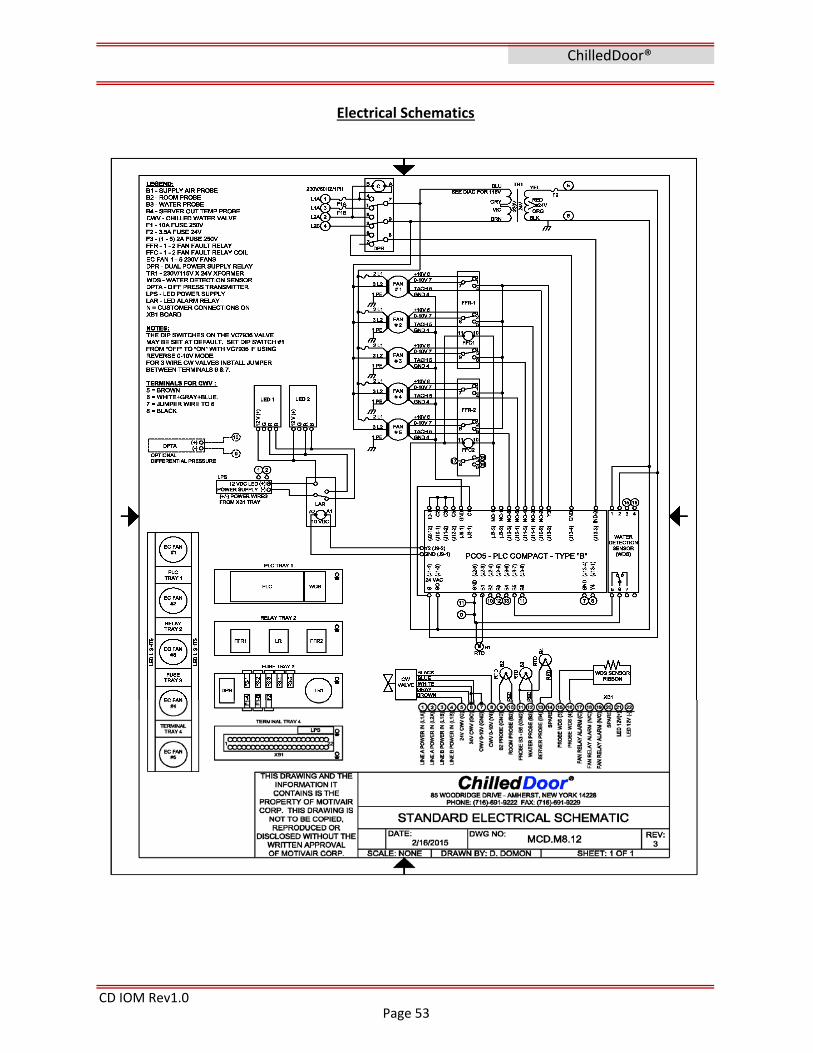
CD IOM Rev1.0
ChilledDoor®
Electrical Schematics
Page 53
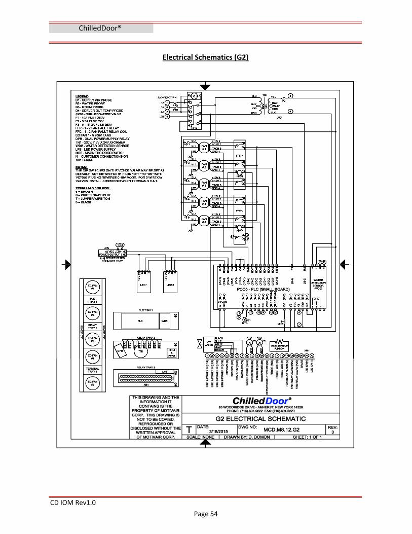
CD IOM Rev1.0
ChilledDoor®
Electrical Schematics (G2)
Page 54

CD IOM Rev1.0
Electrical Schematics (EU‐G2)
ChilledDoor®
Page 55

Section 11
CD IOM Rev1.0
https://motivaircorp.supportsystem.com/account.php?do=create to create an account.
Once an account is created, you can create support tickets from your email account using
A service support portal is available at the following link
Visit the Motivair service portal at
WARRANTY: This product carries a 1‐year Parts Only Warranty. A copy of this warranty is
shipped with your ChilledDoor® Unit. An additional copy of your warranty can be obtained by
contacting Motivair at the address listed on this document. The manufacturer shall not be
liable for any damages resulting from the misapplication or misuse of its products. THIS
EXPRESS WARRANTY IS GIVEN IN LIEU OF ALL OTHER WARRANTIES, EXPRESS, OR IMPLIED, OR
STATUTORY, INCLUDING THE IMPLIED WARRANTIES OF MERCHANTABILITY AND FITNESS FOR
A PARTICULAR PURPOSE, WHICH ARE HEREBY EXCLUDED. MOTIVAIR SHALL NOT BE LIABLE
FOR SPECIAL, INCIDENTAL, OR CONSEQUENTIAL DAMAGES OR LOSSES FROM ANY CAUSE
WHATSOEVER, INCLUDING, WITHOUT LIMITATION, LOSS OF USE, COMMERCIAL PROFITS, OR
CUSTOMER GOODWILL, AND ANY OTHER CLAIMS BASED ON CONTRACT OR TORT, WHETHER
OR NOT ARISING FROM MOTIVAIR’S NEGLIGENCE.
ChilledDoor®
Support <> Contact <> Warranty Information
Factory Service & Support:
www.motivaircorp.com
Additional information on this product may be found at
www.chilleddoor.com
Motivair Corporation
85 Woodridge Drive
Amherst, New York, 14228
716‐691‐9222 Phone
716‐691‐9229 Fax
Parts <> Service <> Technical support Email
SUPPORT & WARRANTY
www.motivaircorp.supportsystem.com also available through our web site link at
www.motivaircorp.com/service‐support
Page 56

Section 12
CD IOM Rev1.0
NOTES:
ChilledDoor®
APPENDIX
Page 57

The VC7936 Fail Safe Modulating Control Valve provides proportional control of hot or chilled water in commercial heating and cooling applications, such as unit ventilators. On a power failure, this patented actuator design drives the valve to the fail safe position, either fully open or closed, according to the installer’s wiring connections.
The VC7936 uses a microprocessor-controlled, low voltage stepper motor with a supercapacitor-based power supply that stores sufficient power to drive the valve to its fail safe position when 24V power is removed from the actuator. DIP switches are used to select actuator response time, flow characterization, motor timing, and control signal type.
A VC hydronic valve consists of a valve body and replaceable characterized cartridge assembly. When used with a Honeywell VC6900 or VC7900-series actuator, the valve provides proportional flow control. Three-way bodies may be used in either diverting or mixing applications. VC valves use cam-operated cartridge travel to resist water hammer. Limit switches prevent motor overrun. These actuators have engineered plastic housing and conformally coated printed circuit boards for humidity resistance. Multiple actuators may be operated by a single controller.
VC7936 Floating Cartridge/Cage Valve
PRODUCT DATA
Specifications The specifications following are nominal and conform to generally accepted industry standards. Honeywell is not responsible for damages resulting from misapplication or misuse of its products.
Power: 24 V, 50-60 Hz, 12 W. Class 2 circuit 18 VA maximum (during start up).
Analog Control Signal: 0–10 or 2–10 Vdc, proportional signal into polarity-protected, 19 kiloohm input impedance. 4–20 mA dc proportional signal with external 499 ohm 1% dropping resistor (not included).
Digital Control Signal: 24 Vac, 1.5mA Floating Signal (two mutually-exclusive momentary contacts for open and close, with minimum 0.5 seconds on and off timing.) 24 Vac, 1.5mA Pulse Width Modulated Signal (repeating voltage pulse up to 30 second period, with minimum 0.5 seconds on and off timing.) 24 Vac, 1.5mA on-off control (contact closure over 30 seconds in duration, not suitable for use with power stealing thermostats or thermostats with anticipators)
Annunciation: red LED on cable end. Nominal Control Timing:
60 or 120 seconds full stroke depending on DIP switch setting. Electrical Termination:
5 feet [1.5 m] plenum-rated cable per UL94-5V. Flexible conduit (3/8") clamp included.
Operating Ambient: 32 to 150°F [0 to +65 C]. 5-95% RH (non-condensing)
Shipping and Storage Temperature: -40 to 150°F [-40 to +65 C]
Atmosphere: Non-corrosive, non-explosive. Approvals:
UL (plenum rating), CE (pending) FCC Part 15 Class B
Fluid temperatures: 34 to 203°F [1 to 95 C] Pressure Rating:
Static - 300 psi [20 Bar] maximum. Burst - 1500 psi [100 Bar]
Operating Differential and Close-off: 60 psi maximum [4 bar]
Stem Travel: 0.4 inches [10 mm] Flow Characteristics:
Linear or equal percentage, per Table 3 and DIP switch setting.
02.11• © Honeywell Limited. 2002 • Form Number 95C-10904-1

VC7936 MODELS:
Actuator: VC7936ZZ11, see Table 1
Bodies (order separately) : VCZ..., see table 3
Table 1. VC7936 Actuator factory settings
A B B
AB
A
94 [3-3/4]
DD 90 [3-9/16]90 [3-9/16]
C
94 [3-3/4]
C
68 [2-3/4]
EE
VC Valve assembled dimensions for reference (Fig. 1 & Table 2)
Figure 1: Nominal dimensions in inches [millimetres].
2-way 1000 1100 1400 1500 1600
Valve [5] Cartridge [4]
Number Pipe Fitting Sizes
VCZAF 1/2" BSPP (int.) [2] 2.6 0.6 1.1 VCZAB 1/2" BSPT (int.) 2.9 0.6 1.1 VCZAJ 3/4" BSPP (int.) 3.3 0.7 1.3 VCZAK 3/4" BSPT (int.) 0.7 1.3 VCZAH 3/4" BSPP (ext.) VCZAG 22MM Compression [3] 4.6 3.7 VCZAP 1" BSPP (int) 5.7 3.6 0.7 1.3 VCZAQ 1" BSPP (ext.) 5.3 VCZAT 1" BSPT (int.) 5.7 VCZAN 28 MM Compression [3] 5.4
VCZAC 3/8" FLARE [1] 2.1 VCZAA 1/2" SWEAT 3.2 2.9 0.7 1.3 VCZAD 1/2" FLARE [1] 3.1 VCZAE 1/2" INVERTED FLARE [1] 3.2 VCZBB 1/2" NPT (int.) 3.4 2.9 0.7 1.3 VCZAL 3/4" NPT (int.) 4.7 VCZAM 3/4" SWEAT 4.6 VCZAR 1" NPT (int.) 6.6 VCZAS 1" SWEAT 6.2 VCZBE 1-1/4" SWEAT VCZBD 1-1/4" NPT (int.)
3-way 6000 6100 6400 6500 6600
Valve [5] Cartridge
Number Pipe Fitting Sizes
VCZME 1/2" BSPP (int.) [2] 3.2 VCZMN 1/2" BSPT (int.) 3.3 VCZMH 3/4" BSPP (int.) 5.9 VCZMJ 3/4" BSPT (int.) 5.3 VCZMG 3/4" BSPP (ext.) 6.9 5.7 VCZMF 22 mm Compression [3] 7.1 5.9 VCZMP 1" BSPP (int) 6.4 VCZMQ 1" BSPP (ext.) 6.8 VCZMT 1" BSPT (int.) 6.9 VCZMM 28 mm Compression [3] 6.4
VCZMB 3/8" FLARE [1] 2.7 VCZMA 1/2" SWEAT VCZMC 1/2" FLARE [1] VCZMD 1/2" INVERTED FLARE [1] 4.2 VCZNB 1/2" NPT (int.) 3.7 VCZMK 3/4" NPT (int.) 6.6 VCZML 3/4" SWEAT 5.9 VCZMR 1" NPT (int.) 8.6 VCZMS 1" SWEAT 6.6 VCZNE 1-1/4" SWEAT VCZND 1-1/4" NPT (int.)
Quick Open
Linear
[6]
[1] No adapters
[2] Suitable for use as 15 mm compression fitting
[3] Includes compression nuts and olives [4] "1200" series cartridge has the same Cv/kV rating as "1100" series.
Suitable for use in potable water appications.
Nominal kvs Rating [8]
3.0
5.3 4.5
6.0
NORTH AMERICA STANDARD MODELS Nominal Cv Rating
3.9
0.8 1.5
4.2
7.0
Nominal kvs Rating [8]
3.4
7.0
7.7
NORTH AMERICA STANDARD MODELS Nominal Cv Rating
3.8
8.6
FLOW CHARACTERISTIC Equal Percentage
APPLICATION On-Off [7]
Modulating
Model Series
Voltage (50/60 Hz)
Action Control Signal
Flow Characteristic
Nominal Stroke Timing
VC7936 24 Vac Direct Acting
0-10 or 2-10 Vdc
Linear
120 seconds.
Fail Safe Return: 12 seconds
[4] Dimensio n
Pipe Fitting Sizes
C D E
mm Inches mm Inches mm Inches
1/2" BSPP (int.) [2] 98 3-7/8 111 4-3/8 136 5-11/32
1/2" BSPT (int.)
3/4" BSPP (int.)
94 3-11/16
113 4-7/16
130 5-1/83/4" BSPT (int.)
3/4" BSPP (ext.)
22mm Compression [3] 112 4-7/16 140 5-1/2
1" BSPP (int.) 94 3-11/16 136 5-11/32
1" BSPP (ext.) 95 3-11/17 114 4-7/17 137 5-11/33
1" BSPT (int.) 94 3-11/16 113 4-7/16
136 5-11/32
28mm Compression [3] 116 4-9/16 147 5-13/16
NORTH AMERICA STANDARD MODELS
3/8" FLARE [1] 98 3-7/8
111 4-3/8
136 5-11/32
1/2" SWEAT 89 3-1/2 130 5-1/8
1/2" FLARE [1]
98 3-7/8 136 5-11/321/2" INVERTED FLARE [1]
1/2" NPT (int.)
3/4" NPT (int.)
94 3-11/16 113 4-7/16
130 5-1/8
3/4" SWEAT 132 5-3/16
1" NPT (int.) 136
1" SWEAT 5-11/32
1-1/4" SWEAT 110 4-5/16 118 4-5/8 142 5-5/8
1-1/4" NPT (int.)
[1] No adapters
[2] Suitable for use as15 mm compression fitting
[3] Dimensions shown with nuts and olives installed [4] Some models not available in all countries
[5] Model availability is country specific.
Some models are not available in all countries
[6] Can be used for modulating with appropriate software
[7] Use balancing valve for very low flow on-off applications
[8] Multiply the kv rating by 1.167 to obtain Cv rating Example: 2-way, 3/4" BSPT (internally threaded) valve number VCZAJ1400
has a kv rating of 3.9; 3-way 1/2" Sweat valve number
VCzMA6100 has a Cv rating of 3.8.
Table 2: VC valve assembled dimensions Table 3: VC Series Valve Bodies
2

12
3
4
VC7936 INSTALLATION WHEN INSTALLING THIS PRODUCT: 1. Read these instructions carefully. Failure to follow them could
damage the product.
2. Check the ratings given in the instructions and on the product to make sure the product is suitable for your application.
3. Installer must be a trained, experienced service technician.
4. Always conduct a thorough check-out when installation is completed.
5. While not necessary to remove the actuator from the body, it can be removed for ease of installation. The actuator can be installed in any of the four orientations to suit the most convenient wiring direction. Actuator latching mechanism works only when the lengths of the actuator and the valve body are parallel to each other.
6. An extra 1" (25 mm) head clearance is required to remove the actuator.
! IMPORTANT: For trouble-free operation of the product, good installation practice must include initial system flushing, chemical water treatment, and the use of a 50 micron (or finer) system side stream filter(s).
The manual lever is used both as a position indicator and as a manual opener to allow initial system flushing.
Alternatively, reusable flush caps, part # 272866B, may be purchased separately for use in initial flushing of dirty hydronic systems.
!! IMPORTANT:
Do not use boiler additives and wetted materials which are petroleum based or contain mineral oil, hydrocarbons, or ethylene glycol acetate. Compounds which can be used, with minimum 50% water dilution, are diethylene glycol, ethylene glycol, and propylene glycol (antifreeze solutions).
PLUMBING The valve may be plumbed in any angle but preferably not with the actuator below horizontal level of the body. Make sure there is enough room around the actuator for servicing or replacement. Refer to installation & instruction sheet 95C-10919 for valve installation instructions.
TO INSTALL ACTUATOR Installation of a new actuator does not require draining the system, provided the valve body and valve cartridge assembly remain in the pipes. Wiring may be done either before or after the actuator is installed. 1. The actuator head is automatically latched to the valve. Align the
coupling hole in the bottom of the actuator with the valve stem. Press the actuator down towards the body with moderate hand force and turn the actuator counter-clockwise by 1/8 turn (45 degrees) to line up the actuator with the piping. The latch will click when engaged. See Figure 5.
Note: The actuator can also be installed at right angles to the valve body but in this position the latch mechanism will not engage. 2. Connect lead wires. See figure 6 for flexible conduit installation
with plenum-cable models.
Fig. 5 - Latch Mechanism to detach Actuator
4
1 2
3
3/8" flex
conduit
Fig. 6 - Flexible Conduit Attachment
WIRING
! CAUTION
1. Disconnect power supply before connecting wiring to prevent electrical shock and equipment damage.
2. Never jumper the supply wires or actuator terminals even temporarily. This may damage the controller.
3. Verify wiring connections of the brown and blue lead wires with respect tot he controller. The actuator will not operate if these are wrong. The blue lead must connect to the controller’s common terminal when using analog inputs. However, digital inputs are switched from the “hot” side of the controller’s power supply.
4. Multiple valves may be connected in parallel to a single controller and transformer, up to the current rating of the controller and transformer.
3

VC7936 VC7936 - INSTALLATION
OPTION SWITCH SETTINGS The VC 7936 has four DIP switches for setting operating characteristics. These are accessible through the slots in the upper part of the case on the end of the actuator with the wiring connections, and may be operated with the tip of a mechanical pencil, or a straightened paper clip. A DIP switch is ON when the switch lever has been moved UP, away from the valve body. They number 1 to 4 from left to right. See table 4.
DIP SWITCH
1 2 3 4
ON REV 0-10V EQUAL % 60 S
OFF DIR FLOATING LINEAR 120 S
Table 4: Dip switch on/off selection for operating characteristics
Sw.1 sets the actuator response. OFF = direct (normal) operation: A port open with 10 Vdc input (factory setting). ON = reverse operation, A port closed with 10 Vdc input. This is useful, for example, for correcting plumbing errors with 3-way valves. This setting affects all control modes.
Sw.2 sets control signal type. OFF = floating, PWM, or on-off (digital) inputs. ON = analog voltage modulating input (factory setting). The VC7936 accepts a variety of control inputs.
Sw.3 sets valve flow characterization. OFF = linear response, where the stem position is a linear function of the input voltage, and flow is solely a function of the valve body (factory setting). ON = equal percentage, where the stem position is a 50% equal percent function of input voltage. Equal percentage response improves comfort control during mild weather in heating systems with constant, high temperature supply water, or in chilled water systems in arid desert climates. Please refer to the Honeywell Engineering Manual of Automatic Control, publication #77-1100, for a detailed explanation.
Sw.4 sets actuator timing. OFF = 2 minute end-to-end valve travel (factory setting). ON = 1 minute travel. The faster response may be needed in lower mass systems.
OPERATION
WITH SERIES 70 MODULATING CONTROLLER Refer to figure 7, DIP switch #2 must be ON (factory default) The controller output may be either 0 to 10 Vdc or 2 to 10 Vdc, but the VC7936 will be closed at 2 V to minimize false control signals caused by induced electrical noise on the wiring. In direct acting mode (DIP switch #1 off), the valve will be fully closed with a 2 V or lower signal, and fully open with a 10 V signal. In reverse acting mode, 10 V is closed and 2 V is open. For a 4-20 mA control signal, wire a 499 ohm, 1/2 W resistor between the black and brown actuator input leads to develop a 2–10Vdc signal. If the controller is nearby, the resistor may be installed on the controller’s terminal block. See figure 8.
Brown (+)
~
Black
Blue (0V)
Gray
WhitePFR*
0-10 Vdc Controller
24 Vac
0V
24V
VC7936
Orange (Insulate)
Sw.2=On
*Valve PFR Position Connect Wires Close “port A” White + Gray + Brown Open “port A” White + Gray + Blue
Fig. 7 - Wiring Color Code for Cable Models for Modulating (0-10V or 2-10V) Controller
Brown (+)
~
Black
Blue (0V)
Gray
WhitePFR*
4-20 mA Controller
24 Vac
0V
24V
Orange (Insulate)51
0 ΩΩΩΩ
VC7936 Sw.2=On
*Valve PFR Position Connect Wires Close “port A” White + Gray + Brown Open “port A” White + Gray + Blue
Fig. 8 - Wiring Color Code for Cable Models for Modulating (420mA) Controller
WITH SERIES 60 FLOATING (TRISTATE) CONTROLLER Refer to figure 9, DIP switch #2 must be OFF, switch #1 = OFF. A Series 60 floating controller has SPDT contact closure outputs with a center-off position. On a change in temperature from the set point, the controller will close either the Open or Close contacts creating a momentary voltage pulse on the gray or white input leads, driving the valve to a new position. The pulse must be at least 1/2 second long in order to be detected by the VC7936. The pulse can be held as long as necessary. For control stability, the stroke time of the actuator while powered has been simulated at either 120 or 60 seconds, depending on DIP switch #4. In fail safe and testing operation, the actuator travels through its stroke in 12 seconds.
Fig. 9 - Wiring Color Code for Cable Models for Floating (Series 60 or "tristate) Controller
95C-10904-1 4

VC7936 - WIRING, OPERATION, SERVICE, CHECK-OUT WITH SERIES 70 PWM CONTROLLER Refer to figure 10, DIP switch #2 must be OFF A Pulse Width Modulating controller has a SPST contact closure output that supplies a repetitive voltage pulse. The duty cycle of the pulse (percentage on time) is proportional to the position of the valve. This control signal was originally developed for use with electromechanical thermal actuators. If the VC7936 sees the a voltage pulse simultaneously on the gray and white input leads, it automatically interprets this as a PWM signal, and changes the valve to the new position on the second pulse. PWM pulses must be at least 1/2 second long in order to be detected by the VC7936. A 1/2 second pulse is interpreted as an Off signal. The pulse period may be up to 30 seconds, and pulses must be separated by an off period no shorter than 1/2 second. The VC7936 will automatically synchronize to the period of the pulse train. If DIP switch #1 is on, valve position is proportional to the off time percentage of the pulse train.
Fig. 10 - Wiring Color Code for Cable Models for Pulse Width Modulating (PWM) Controller
WITH SERIES 80 ON-OFF CONTROLLER Refer to figure 11, DIP switch #2 must be OFF A Series 80 controller has a SPST contact closure output that supplies 24V power to the controlled device. VC7936 wiring is identical to the PWM installation, above. If a “PWM” pulse extends longer than 30 seconds, the VC7936 interprets this as an on-off control signal, and opens the valve at its 12 second speed. Note that the valve response is delayed by 42 seconds from application of the controller signal. If DIP switch #1 is on, the valve closes when the signal is received. NOTE: the current draw of the control inputs of the VC7936 is not high enough to operate either a power stealing electronic thermostat, or the anticipator of an electromechanical low voltage thermostat.
Fig. 11 - Wiring Color Code for Cable Models for ON-Off (Seroes 80) Controller
POWER FAILURE REPOSITION (FAIL SAFE OPERATION) On a loss of power, the actuator will drive to its stand-by position using energy stored in the super-capacitors, and will resume normal operation on power up. On loss of signal, a VC7936 wired for PFR-
Open will open the A port fully. A VC7936 wired for PFR-Close will open the A port fully. The motor can drive the valve through its full stroke in 12 seconds.
PFR position is chosen during installation. In analog mode (DIP switch #2 ON), the white and gray wires are connected to signal common (blue) to fail safe open, or to 24 V (brown) to fail safe closed. In digital mode (DIP switch #2 OFF), the black wire is connected to common (blue) to fail safe open, or to 24 V (brown) to fail safe closed.
The PFR position can be controlled dynamically with a SPST signal by applying 24 V power to the appropriate PFR direction selection lead(s) while power is present. Applying 24 V will cause the valve to close the A port when power is lost. Not applying power will cause the valve to open the A port when power is lost. This can be useful in 2-pipe systems where both hot and chilled water may be used depending on the season, and a different fail safe mode is required for each condition.
Because of the soft close off characteristic of the VC valve, initial (and final) movements of the actuator do not cause significant changes in the valve stem position.
START UP On initial power-up, the capacitors will take about 60 seconds to charge. When ready, the actuator will drive the valve through one full stroke cycle over 24 seconds to calibrate its position, and exercise the valve cartridge. The self-calibration compensates for motor tolerance and lets one controller operate multiple VC7936. This self-calibration action repeats daily. If anything interferes with the self-calibration process, the LED will flash rapidly and the actuator will not respond to control signals.
CHECK-OUT 1. Raise the set point of the thermostat above room temperature to
initiate a call for heat.
2. Observe all control devices - 2 way valve should open. Port A in 3way valve should open, and port B should close in 90 seconds.
3. Lower the set point of the thermostat below room temperature.
4. Observe the control devices. 2 way valve should close. Port A in 3-way valve should close, and port B should open in 90 seconds.
5. Remove power from actuator. Actuator waits 3 seconds then drives valve to default position, i.e.: open (or closed), in 12 seconds or less.
6. Restore power to actuator. Valve should drive to the position required by the thermostat or controller in 90 seconds or less.
SERVICE This valve should be serviced by a trained, experienced service technician. 1. If the valve is leaking, drain system OR isolate valve from the
system. Do not remove valve body from plumbing.
2. Check to see if the cartridge needs to be replaced.
3. If the motor or other internal parts of the actuator is damaged, replace the entire actuator assembly.
NOTE: Honeywell hydronic valves are designed and tested for silent operation in properly designed and installed systems. However, water noises may occur as a result of excessive water velocity. Piping noises may also occur in high temperature (over 212oF [100oC]) systems with insufficient water pressure.
5

VC7936
TO REPLACE ACTUATOR Replacement of an actuator does not require draining the system, provided the valve body and valve cartridge assembly remain in the pipeline. 1. Check replacement part number and voltage ratings for match
with old device.
2. Disconnect power supply before servicing to avoid electrical shock or equipment damage.
3. Disconnect leadwires to actuator and remove. Where appropriate, label wires for rewiring.
4. The actuator head is automatically latched to the valve. To remove, press up on the latch mechanism with your thumb. It is located directly below the white manual open lever (see figure 5 below). Simultaneously press the actuator down towards the body with moderate hand force and turn the actuator counterclockwise by 1/8 turn (45 degrees). Lift the actuator off the valve body.
5. Install the new actuator by reversing the process in (4).
6. Reconnect leadwires.
7. Restore power, and check out operation.
Automation and Control Solutions In Canada: Environmental Control Products Honeywell Limited-Limitee 1985 Douglas Drive North 35 Dynamic Drive Printed in Canada Golden Valley, MN 55422-3992 Toronto, ON M1V 4Z9
By using this Honeywell literature, you agree that Honeywell will have no liability for any damages arising out of your use or modification to, the literature. You will defend and indemnify Honeywell, its affiliates and subsidiaries, from and against any liability, cost, or damages, including attorneys’ fees, arising out of, or resulting from, any modification to the literature by you.