i/otm series - weigl control · new ip adress is stored in ee-prom. set ip adress on network 2 on...
TRANSCRIPT

WEIGL ASCII-Commands for ProCommander® X Series, ProCommander® Series, WEMC-1, PrismTagTM Series and Pro I/OTM Series
Each command starts with a "!", terminator: "#".
The programmer has to take care of the correct syntax!
Wrong commands are ignored or lead to a unexpected result!
Trigger Event Name Parameter Example-Explanation InfoInput events: Stored in Control.ini file on memory card This commands are only possible in the Control.ini file
!iXc!...# Input x close X: input ID from 1 to 16.
further commands
!i1c!esd2:"Hello World"# If input 1 is closed, then send "Hello World" on serial port RS232-2.
!iXo!...# Input x open X: input ID from 1 to 16.
further commands
!i2o!pst\AUDIO\TRACK001.OGG# If input 2 opens, then play single track "TRACK001.OGG" of folder AUDIO
!iXt!...# Input x toggle X: input ID from 1 to 16.
further commands
!i3t!edf1:20<10# If input 3 toggles, then fade DMX channel 1 from current value within 10 seconds to value 20.
Time events: Stored in Control.ini file on memory card This commands are only possible in the Control.ini file
!tmXX:YY!...# Absolute time after powering on or
after the insertion of a flash card.
XX = minutes
YY = seconds
!tm135:20!rsn1#
!tm01:20!...#
At 2 hours, 15 minutes and 20 seconds, after powering on the ProCommander® or after the
insertion of a flash card, the first show will be started in normal mode.
If the time 1 minute 20 seconds is reached after the start-up or plug in of the card, then the
downstream command will be executed.
!t&XX:YY!...# At any time the value is reached the
downstream is executed.
XX = minutes
YY = seconds
!t&05:00!...# All 5 minutes the downstream command will be executed.
Real time clock events: Stored in Control.ini file on memory card This commands are only possible in the Control.ini file
!rc…!...# Time-controlled events with the
internal real time clock.
If no battery is inserted the command will be
executed with a delay!
!rc(X=Y)!...# =: is equal to !rc(h=8)!rsa3#
!rc(d=24;o=12;y16)!rsn1#
!rc(h=4;m=20)!rsnl1#
At 8 o'clock the third show starts in add mode.
December 24th 2016 starts the first show in normal mode.
The first show starts at 4:20 a.m. and runs in a loop, if a battery is inserted and the real time
clock is activated. If no battery is inserted the command will be executed with a delay of 20
hours and 20 minutes. Because every time you power up the device or plug in a memory card
the internal clock is set to 08:00 a.m..
!rc(X<Y)!...# <: is less than !rc(o<5)!...# Till may the downstream command will be executed.
!rc(X>Y)!...# >: is greater than !rc(d>13; h=9)!...#
!rc(w>2;w<7;h=8)!...#
At 9 o'clock from the 13th till the end of each month the downstream command will be
executed.
From Tuesday till Saturday the downstream command will be executed precisely at 8 a.m.
!rc(X&Y)!...# &: modulo !rc(m&15)!...#
!rc(s&10)!...#
At every quater (15, 30, 45, 0) the downstream command will be executed.
Every 10 seconds the downstream command will be executed.
WEIGL ASCII-Commands for ProCommander® X Series, ProCommander® Series, WEMC-1, PrismTagTM
Series & Pro
I/OTM SeriesDefault connection parameter: 9600 baud, 8 data bits, no parity, 1 stop bit. Port: RS232-1
If these serial parameters are changed, the transmitter must be changed to the same parameters!
Maximum length of a serial string for port RS232-1: 150 characters.
Commands marked in this colour are only possible in the Control.ini file!
Commands marked in this colour are not implemented yet!
Structure of the Control.ini file: It must always start with the definition of a trigger event. As a start condition either an input, time, real time clock, variable, DMX or infrared event
X: weekday/ day/ month/ year/ hour/ minute/
seconds
Y: value
w = weekday (value range: 1-7; Monday = 1,
Sunday = 7)
d = day (value range: 1-31).
o = month (value range: 1-12).
y = year (value range: 16-17; corresponds 2016
to 2017).
h = hour (value range: 0-23).
m = minute (value range: 0-59).
s = seconds (value range: 0-59).
www.weigl.support
© 2007 – 2018 – Weigl GmbH Co KG
Page 1 / 21

WEIGL ASCII-Commands for ProCommander® X Series, ProCommander® Series, WEMC-1, PrismTagTM Series and Pro I/OTM Series
Trigger Event Name Parameter Example-Explanation InfoDMX events: Stored in Control.ini file on memory card This commands are only possible in the Control.ini file
!d...!...# The whole DMX univers can als be
used as a start condition for a
command line.
As operators > < = are permitted.
!dX=Y!...# =: is equal to X: DMX channel
Y: Value of the DMX channel
!d1=255!...# If the value of the DMX channel 1 is equal 255, than the downstream command will be
executed.
!dX<Y!...# <: is less than X: DMX channel
Y: Value of the DMX channel
!d150<20!...# If the value of the DMX channel 150 is less than 20, than the downstream command will be
executed.
!dX>Y!...# >: is greater than X: DMX channel
Y: Value of the DMX channel
!d512>175!...# If the value of the DMX channel 512 is greater than 175, than the downstream command will be
executed.
Infrared commands: Stored in Control.ini file on memory card This commands are only possible in the Control.ini file
!k…!...# A infrared remote control can be
used to start a command line. (Only if
the device is capable of infrared).
Input 1 to 10 can be used, whereby the digit 0 is
equivalent to 10.
!kXc!...# Input x open X: input ID from 1 to 16.
further commands
!k1c!...# If input 1 on the infrared remote control is activated (c=close), than the downstream command
will be executed.
!kXo!...# Input x open X: input ID from 1 to 16.
further commands
!k5o!...# If input 5 on the infrared remote control is deactivated (o=open), than the
downstreamcommand will be executed.
!kXt!...# Input x toggle X: input ID from 1 to 16.
further commands
!k0t!...# If input 10 on the infrared remote control changes (t=toggle), than the downstream command
will be executed.
www.weigl.support
© 2007 – 2018 – Weigl GmbH Co KG
Page 2 / 21

WEIGL ASCII-Commands for ProCommander® X Series, ProCommander® Series, WEMC-1, PrismTagTM Series and Pro I/OTM Series
Command Name Parameter Example-Explanation Info
Get configuration:
!?# !?# list the current settings of the unit.
Set commands: cd all changes with the set commands are stored
in the internal EE-Prom
!sfactory# Set factory !sfactory# all settings are switched back to the default factory settings.
!sreboot# Reboot unit !sreboot# reboots the unit in the same way as a power cycle would do.
!sip..# Set IP-address IP-Address;
@2: Network port 2 for ProCommander® X
Series
!sip10.0.0.100#
!sip10.0.0.105@2#
new IP Adress is stored in EE-Prom.
Set IP Adress on network 2 on ProCommander® AX to 10.0.0.105.
!sim..# Set IP-address and sub-net mask MAC-address, IP-Address, sub-net mask !sim:00-1E-C0-81-58-75:10.0.3.100:255.255.252.0# in device with MAC-address 00-1E-C0-81-58-75 the IP Adress 10.0.3.100 and new sub-net mask
255.255.252.0 is stored in EE-Prom.
!spo1..# Set port1 -- port4 Port [0000 -- 65534] !spo15555# new Port1 -- 4 is stored in EE-Prom.
!sgi..# Set Gateway IP-address IP-Address !sgi10.0.0.105# new Gateway IP Adress is stored in EE-Prom.
!smc..# Set Multicast IP-address IP-Address !smc224.0.0.105# Set multicast IP Adress to port number 2.
!ssm..# Set sub-net mask Sub-Net Mask !ssm255.255.255.0# new Sub-Net-Mask is stored in EE-Prom.
!swp1..# Set WEM-NET port Port [1..4] !swp3# Defines port 3 as port, which will be used for WEM-NET cues.
!smv..# Set master volume Master Volume [0 -- 31];
Channel number [1--8] for ProCommander® LX
only.
!smv25#
!smv10:2#
new Master Volume level is stored in EE-Prom. ProLX: all channels are set to volume 25.
ProLX: set volume level 10 on audio channel 2.
!smb..# Set master bass Master Bass [0 -- 15]];
Channel number [1--8] for ProCommander® LX
only.
!smb10#
!smb5:3#
new Master Bass value is stored in EE-Prom. ProLX: all channels are set to bass value 10.
ProLX: set bass value 5 on audio channel 3.
!smt..# Set master treble Master Treble [0 -- 15]];
Channel number [1--8] for ProCommander® LX
only.
!smt10#
!smt5:3#
new Master Treble value is stored in EE-Prom. ProLX: all channels are set to treble 10.
ProLX: set treble value 5 on audio channel 3.
!sag..# Set amplifier gain for built in 20W
amplifier
Gain factor [1..4] !sag1#
!sag2#
!sag3#
!sag4#
Set amplifier gain to 1 (=20dB)
Set amplifier gain to 2 (=26dB)
Set amplifier gain to 3 (=32dB)
Set amplifier gain to 1 (=36dB)
!sdm..# set DMX-merge mode DMX-Merge Mode [0 -- 5]
0: Merge-None
1: Merge-LTP
2: Merge-HTP
3: Merge-Change
4: Merge-Add
5: Merge-Combine
!sdm2# new Merge-Mode is stored in EE-Prom.
0: Merge-Mode disabeld (default).
1: Output is the lowest value of both DMX signals.
2: Output is the highest value of both DMX signals.
3: Output is that value, which has changed at last.
4: The values of both DMX signals are added; maximum value = 255.
5: Between Start- and End-Channel the output follows the external DMX-Signal.
!sds..# Set DMX-merge start channel DMX-Merge Start channel [1 -- 512] !sds100# new DMX-Merge Start channel is stored in EE-Prom.
!sde..# Set DMX-merge end channel DMX-Merge End channel [1 -- 512] !sds200# new DMX-Merge End channel is stored in EE-Prom.
!scc..# Set RS232 Configuration RS232-ID: 1-3;
Configuration: Baud: 1200, 2400, 4800, 9600,
19200, 38400, 57600, 115200, 250000, 400000,
1000000;
DataBits : 5-8;
Parity: Even, Odd, No parity;
Stopbits: 1-2.
!scc1=9600,8N1#
!scc2=115200,7E2#
!scc3=57600,8O1#
set RS232-1 to 9600Baud, 8 databits, No parity, 1 Stopbit.
set RS232-2 to 115200Baud, 7 databits, Even parity, 2 Stopbits.
set RS232-3 to 57600Baud, 8 databits, Odd parity, 1 Stopbit.
If Merge-Mode is enabled, it is only valied between start- and end-channel.
www.weigl.support
© 2007 – 2018 – Weigl GmbH Co KG
Page 3 / 21

WEIGL ASCII-Commands for ProCommander® X Series, ProCommander® Series, WEMC-1, PrismTagTM Series and Pro I/OTM Series
Command Name Parameter Example-Explanation Info!scd..# Set RS232 Driver-ID RS232-ID: 1-3;
Driver-ID: 0,1,…
0: No driver;
1: SMCI47 - Nanotec
2: Dynamixel 10Bit
3: IAI (not implemented)
4: RS485
5: Target
6: Dynamixel 12Bit
!scd1=0#
!scd1=1#
!scd2=2#
!scd3=2#
set RS232-1 to no driver.
set RS232-1 to SMCI47 Servo-unit from Nanotec.
set RS232-2 to Dynamixel Servo-unit from Robotis.
set Pro I/OTM Servo RS485 Output to Dynamixel Servo-unit from Robotis.
!sdp..# Set Driver-Parameter RS232-ID: 1-3;
Parameter-ID: 1,2,…
Value: 0..1000000
!sdp1:1=0#
!sdp1:2=100000#
!sdp2:1=0#
for serial driver of RS232-1 set driver parameter 1 (1=minimum value) to 0.
for serial driver of RS232-1 set driver parameter 2 (2=maximum value) to 100000.
for serial driver of RS232-2 set driver parameter 1 (1=minimum value) to 0.
!sda..# Set DMX2Analog start channel. DMX-Start channel [1 -- 512] for Analog map !sda2# The analog outputs are mapped to the consecutive DMX channels beginning with channel 2.
!sma..# Set DMX2Analog mask Mask for analog outputs;
1: set, 0: clear; left alignement.
A 1 indicates, that the corresponding DMX
channel is mapped to the analo output. With a 0
the DMX channel will be ignored and the analog
output may be controlled internally.
!sma1111111100000000#
!sma1111111111111111#
!sma1111000011110000#
The four analog outputs and the four R/C servo outputs are mapped to the DMX channels.
The four analog outputs, the four R/C servo outputs and the eight PWM outputs are mapped to
the DMX channels.
The four analog outputs and the first four PWM outputs are mapped to the DMX channels.
!!!The eight PWM channels share with the digital channels 9-16. If PWM and digital
channels are mapped to DMX, the digital channels 9-16 must be masked!!!
!sdd..# Set DMX2Digital start channel. DMX-Start channel [1 -- 512] for Digital map !sdd18# The digital (OpenCollector) outputs are mapped to the consecutive DMX channels beginning
with channel 18.
!smd..# Set DMX2Digital mask Mask for digital outputs;
1: set, 0: clear; left alignement.
A 1 indicates, that the corresponding DMX
channel is mapped to the digital output. With a
0 the DMX channel will be ignored and the
digital output may be controlled internally.
!smd1111111100000000#
!smd1111111111111111#
!smd1111000011110000#
!smd1111111100000000#
The first 8 digital channels are mapped to the DMX channels.
All 16 digital outputs are mapped to the DMX channels.
The digital outputs 1-4 and 9-12 are mapped to the DMX channels.
This is a mask example, if the PWM channels are mapped to DMX!
!ssd..# Set Start DMX read channel DMX-Start channel [1 -- 512] for that channel,
which contains the drop-out information.
!ssd1# The first channel of the dmx stream contents the drop out information.
!sdr..# Set DMX read in 1: ON, 0: OFF !sdr1#
!sdr0#
Enable DMX read in.
Disable DMX read in.
!sdt..# Set DMX time out Time: 0--2.5 seconds in 0.01 steps !sdt100# Set DMX time out to 1 second.
!sdfX# Set DMX frame rate X: frame rate values: 10 to 44 !sdf20#
!sdf44#
!sdf0#
Set DMX frame rate to 20 frames per second.
Set DMX frame rate to 44 frames per second (maximum speed)
Switch off frame rate delay, sets DMX signal to maximum speed = 44 frames per second.
!sbdX# Set DMX byte delay X: delay values between 0 and 250
The delay time is value*4µs
!sbd1#
!sbd5#
Additional delay between the DMX bytes of 4µ seconds. Some DMX devices need a longer time
to decode the DMX signal.
Additional delay between the DMX bytes of 20µ seconds.
!stt..# Set time code time out Time: 0--2.5 seconds in 0.01 steps !stt100# Set time code time out to 1 second
www.weigl.support
© 2007 – 2018 – Weigl GmbH Co KG
Page 4 / 21
WEIGL ASCII-Commands for ProCommander® X Series, ProCommander® Series, WEMC-1, PrismTagTM Series and Pro I/OTM Series
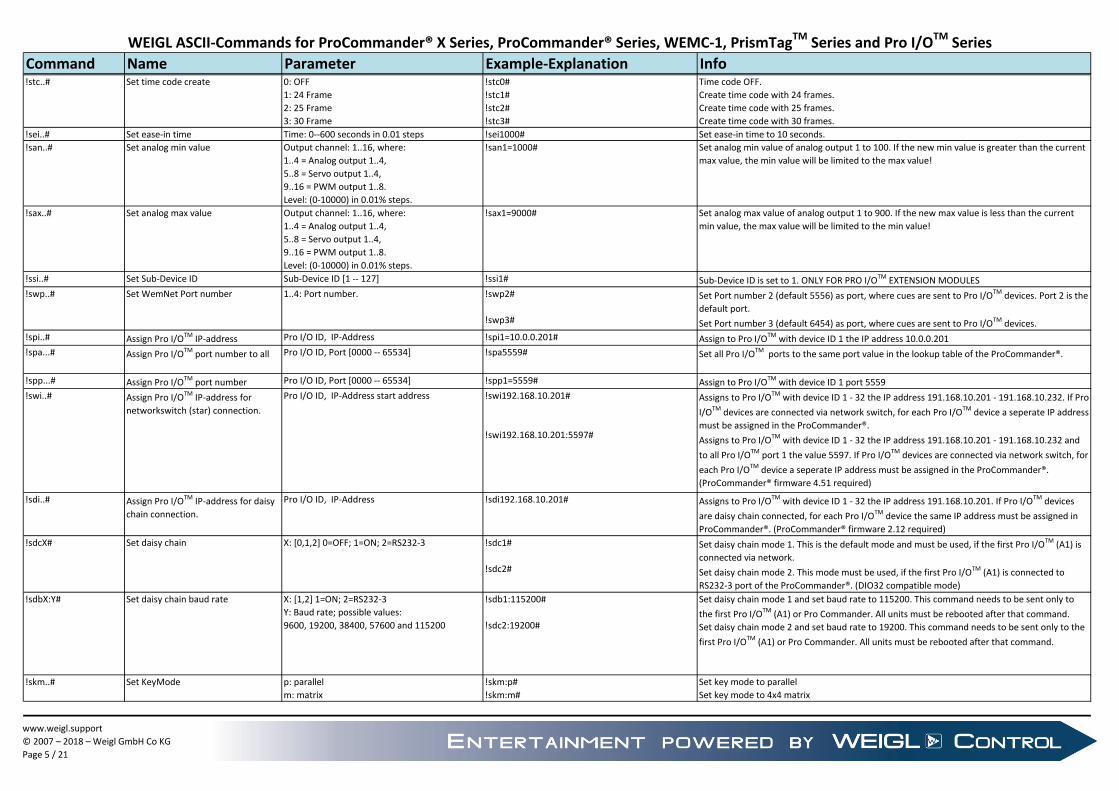
Command Name Parameter Example-Explanation Info!stc..# Set time code create 0: OFF
1: 24 Frame
2: 25 Frame
3: 30 Frame
!stc0#
!stc1#
!stc2#
!stc3#
Time code OFF.
Create time code with 24 frames.
Create time code with 25 frames.
Create time code with 30 frames.
!sei..# Set ease-in time Time: 0--600 seconds in 0.01 steps !sei1000# Set ease-in time to 10 seconds.
!san..# Set analog min value Output channel: 1..16, where:
1..4 = Analog output 1..4,
5..8 = Servo output 1..4,
9..16 = PWM output 1..8.
Level: (0-10000) in 0.01% steps.
!san1=1000# Set analog min value of analog output 1 to 100. If the new min value is greater than the current
max value, the min value will be limited to the max value!
!sax..# Set analog max value Output channel: 1..16, where:
1..4 = Analog output 1..4,
5..8 = Servo output 1..4,
9..16 = PWM output 1..8.
Level: (0-10000) in 0.01% steps.
!sax1=9000# Set analog max value of analog output 1 to 900. If the new max value is less than the current
min value, the max value will be limited to the min value!
!ssi..# Set Sub-Device ID Sub-Device ID [1 -- 127] !ssi1# Sub-Device ID is set to 1. ONLY FOR PRO I/OTM EXTENSION MODULES
!swp..# Set WemNet Port number 1..4: Port number. !swp2#
!swp3#
Set Port number 2 (default 5556) as port, where cues are sent to Pro I/OTM devices. Port 2 is the
default port.
Set Port number 3 (default 6454) as port, where cues are sent to Pro I/OTM devices.
!spi..# Assign Pro I/OTM IP-address Pro I/O ID, IP-Address !spi1=10.0.0.201# Assign to Pro I/OTM with device ID 1 the IP address 10.0.0.201
!spa...# Assign Pro I/OTM port number to all Pro I/O ID, Port [0000 -- 65534] !spa5559# Set all Pro I/OTM ports to the same port value in the lookup table of the ProCommander®.
!spp...# Assign Pro I/OTM port number Pro I/O ID, Port [0000 -- 65534] !spp1=5559# Assign to Pro I/OTM with device ID 1 port 5559
!swi..# Assign Pro I/OTM IP-address for
networkswitch (star) connection.
Pro I/O ID, IP-Address start address !swi192.168.10.201#
!swi192.168.10.201:5597#
Assigns to Pro I/OTM with device ID 1 - 32 the IP address 191.168.10.201 - 191.168.10.232. If Pro
I/OTM devices are connected via network switch, for each Pro I/OTM device a seperate IP address
must be assigned in the ProCommander®.
Assigns to Pro I/OTM with device ID 1 - 32 the IP address 191.168.10.201 - 191.168.10.232 and
to all Pro I/OTM port 1 the value 5597. If Pro I/OTM devices are connected via network switch, for
each Pro I/OTM device a seperate IP address must be assigned in the ProCommander®.
(ProCommander® firmware 4.51 required)
!sdi..# Assign Pro I/OTM IP-address for daisy
chain connection.
Pro I/O ID, IP-Address !sdi192.168.10.201# Assigns to Pro I/OTM with device ID 1 - 32 the IP address 191.168.10.201. If Pro I/OTM devices
are daisy chain connected, for each Pro I/OTM device the same IP address must be assigned in
ProCommander®. (ProCommander® firmware 2.12 required)
!sdcX# Set daisy chain X: [0,1,2] 0=OFF; 1=ON; 2=RS232-3 !sdc1#
!sdc2#
Set daisy chain mode 1. This is the default mode and must be used, if the first Pro I/OTM (A1) is
connected via network.
Set daisy chain mode 2. This mode must be used, if the first Pro I/OTM (A1) is connected to
RS232-3 port of the ProCommander®. (DIO32 compatible mode)
!sdbX:Y# Set daisy chain baud rate X: [1,2] 1=ON; 2=RS232-3
Y: Baud rate; possible values:
9600, 19200, 38400, 57600 and 115200
!sdb1:115200#
!sdc2:19200#
Set daisy chain mode 1 and set baud rate to 115200. This command needs to be sent only to
the first Pro I/OTM (A1) or Pro Commander. All units must be rebooted after that command.
Set daisy chain mode 2 and set baud rate to 19200. This command needs to be sent only to the
first Pro I/OTM (A1) or Pro Commander. All units must be rebooted after that command.
!skm..# Set KeyMode p: parallel
m: matrix
!skm:p#
!skm:m#
Set key mode to parallel
Set key mode to 4x4 matrix
www.weigl.support
© 2007 – 2018 – Weigl GmbH Co KG
Page 5 / 21

WEIGL ASCII-Commands for ProCommander® X Series, ProCommander® Series, WEMC-1, PrismTagTM Series and Pro I/OTM Series
Command Name Parameter Example-Explanation InfoRTCC commands:
!srt..# Set RTCC Time time in format hh:mm.ss
hh: hour from 00 to 23
mm: minute from 00 to 59
ss: seconds from 00 to 59
!srt=08:30.15# Set RTCC time to 8h, 30 minutes and 15 seconds.
!srd..# Set RTCC Date date in format dd.mm.yy:wd
dd: day from [1..31]
mm: month [1..12]
yy: year [12..99]
wd: weekday [1..7] 1= Monday
!srd=20.10.12:1# Set RTCC date to October 20th 2012; Monday.
Change commands: all changes are temporarily with the next
power cycle, the ProCommander® switches
back to the values stored in the EE-Prom
!cip..# Change IP-address IP-Address !cip10.0.0.100# temporarily change of IP Adress.
!cpo1..# Change port1 -- port4 Port [0000 -- 65534] !cpo5555# temporarily change of Port.
!csm..# Change sub-net mask Sub-Net Mask !csm255.255.255.0# temporarily change of Sub-Net-Mask.
!cmv..# Change master volume Master Volume [0 -- 31]
value 32: stored level in EEProm
+: increase one step
-: decrease one step
Channel number [1--8] for ProCommander® LX
only.
!cmv25#
!cmv32#
!cmv+#
!cmv-#
!cmv+:1#
!cmv25:1#
temporarily change of Master Volume level to level 25; (ProLX: all channels).
Change master volume to level stored in EEProm; (ProLX: all channels).
Increase master volume one step; (ProLX: all channels).
Decrease master volume one step; (ProLX: all channels).
Increase master volume one step on audio output 2; (ProCommander® LX only).
Change of Master Volume level to level 25 on audio channel 1. (ProCommander® LX only).
!cfm..# Fade master volume Level: 0--31
Level: 32 => stored level in EEProm.
Time: 0--25.5 seconds in 0.1 steps
time is calculated for the full range from 0 to 31.
If less steps are required, the end value is
reached in a shorter time!
Channel number [1--8] for ProCommander® LX
or PHX only.
!cfm28<10# or !cfm28>100#
!cfm0<5# or !cfm0>50#
!cfm32<8.5# or !cfm32>85#
!cfm28<10:1# or !cfm28>100:1#
(ProCommander® LX: all channels).
Fade to volume level 28 with time 10 seconds. 10 seconds are calculated from 0 to 31.
Fade volume to level 0 with time 5 seconds. 5 seconds are calculated from 0 to 31.
Fade to level stored in EEProm with time 8.5 seconds.
Fade to volume level 28 with time 10 seconds at audio output 1.
!cmb..# Change master bass Master Bass [0 -- 15]];
Channel number [1--8] for ProCommander® LX
only.
!cmb10#
!cmb5:3#
new Master Bass value is 10; ProLX: all channels are set to bass value 10.
ProLX: set bass value 5 on audio channel 3.
!cmt..# Change master treble Master Treble [0 -- 15]];
Channel number [1--8] for ProCommander® LX
only.
!cmt10#
!cmt5:3#
new Master Treble value is 10; ProLX: all channels are set to treble 10.
ProLX: set treble value 5 on audio channel 3.
!cdm..# Change DMX-merge mode DMX-Merge Mode [0 -- 5]
0: Merge-None
1: Merge-LTP
2: Merge-HTP
3: Merge-Change
4: Merge-Add
5: Merge-Combine
!cdm2# temporarily change of Merge-Mode.
0: Merge-Mode disabeld (default).
1: Output is the lowest value of both DMX signals.
2: Output is the highest value of both DMX signals.
3: Output is that value, which has changed at last.
4: The values of both DMX signals are added; maximum value = 255.
5: Between Start- and End-Channel the output follows the external DMX-Signal.
!cds..# Change DMX-merge start channel DMX-Merge Start channel [1 -- 512] !cds100# temporarily change of DMX-Merge Start channel.
!cde..# Change DMX-merge end channel DMX-Merge End channel [1 -- 512] !cde200# temporarily change of DMX-Merge End channel.
If Merge-Mode is enabled, it is only valied between Start- and End-Channel.
www.weigl.support
© 2007 – 2018 – Weigl GmbH Co KG
Page 6 / 21

WEIGL ASCII-Commands for ProCommander® X Series, ProCommander® Series, WEMC-1, PrismTagTM Series and Pro I/OTM Series
Command Name Parameter Example-Explanation Info!cdn..# ChangeDMX min value DMX channel: 1..256
Min value: 0-255.
!cdn1=20#
!cdn1_512=20#
Change DMX min value of DMX channel 1 to 20.
Change DMX min value of DMX channels 1 to 512 to 20.
If the new min value is greater than the current max value, the min value will be limited to the
max value!
!cdx..# Change DMX max value DMX channel: 1..256
Min value: 0-255.
!cdx1=200#
!cdx1_512=200#
Change DMX max value of DMX channel 1 to 200.
Change DMX max value of DMX channels 1 to 512 to 200.
If the new max value is less than the current min value, the max value will be limited to the min
value!
!ctm..# Change scheduler time time in format hh:mm.ss
hh: hour from 00 to 23
mm: minute from 00 to 59
ss: seconds from 00 to 59
!ctm=01:30.15# Change scheduler time to 1h, 30 minutes and 15 seconds
!ctc..# Create Time Code Time Code format:
0: stop time code create
1: 24 frames per second
2: 25 fames per second
3: 30 frames per second
!ctc1#
!ctc2#
!ctc3#
!ctc0#
!ctc3=00:01:02.10#
Create 24 fps time code.
Create 25 fps time code.
Create 30 fps time code.
Stop create time code.
Create 30fps time code and start with 00hour, 01minutes, 02seconds and 10frames.
Run commands:
!rsn..# Start show in normal mode Show number !rsn2#
!rsn:\SHOWS\002Show.wm1#
Normal mode: a showstart is only possible, if no show is running.
!rsa..# Start show in add mode Show number !rsa3# Add mode: if the new show is not running, it will be started additionally to perhaps running
shows.
Attention: Up to 20 shows depending on content and complexity of each show. It needs to be
tested.
!rst..# Start show in terminate mode Show number !rst4# Terminate mode: All shows with a different number to the new show are terminated and the
new show will be started. If the new show is allready running, it continues.
!rsi..# Start show in interrupt mode Show number !rsi5# Interrupt mode: All shows are stopped, the new show will be started.
!rsr..# Start show in restart mode Show number !rsr6# Restart mode: The new show will be started or if it is running, it will be restarted. Other perhaps
running shows continue running.
!rse..# End show Show number !rse7# End: The show will be stopped.
!rps..# Pause show Show number, 0= any show !rps1#
!rps0#
Pause show 1.
Pause any current running show.
!rcs..# Continue show Show number, 0= any show !rcs1#
!rcs0#
Continue show 1
Continue any paused show
www.weigl.support
© 2007 – 2018 – Weigl GmbH Co KG
Page 7 / 21

WEIGL ASCII-Commands for ProCommander® X Series, ProCommander® Series, WEMC-1, PrismTagTM Series and Pro I/OTM Series
Command Name Parameter Example-Explanation Info!rss..# Start show in shuffle mode Show number range !rss3_10# Shuffle mode: one of the shows between 3 and 10 will be started. Shows are handled like
restart. Means, if show is running, it will be restarted. Other running shows continue.
!rsva..# Start show in add mode based on
variable content
Variable number !rsva5# Start show which is equal to the content of variable 5 in add mode. E.g. if variable 5 has the
value 10, then show 10 will be started in add mode.
!rsvt…# Start show in terminate mode based
on variable contenct
Variable number !rsvt6# Start show which is equal to the content of variable 6 in terminate mode. E.g. if variable 6 has
the value 8, then show 8 will be started in terminate mode.
!rpx..# Start polyphonic show in restart
mode
Show number !rpx6# Only available for Pro Commander PHX. Audio of that show will be mixed to audio of audio
channel 1.
Restart mode: The new show will be started or if it is running, it will be restarted. Other perhaps
running shows continue running.
!rtc..# Sync to external time code ON/OFF: 0=OFF, 1=ON
Time: 0--600 seconds in 0.01 steps.
Values between 2 and 60000 (=600sec).
!rtc1#
!rtc100#
!rtc0#
Sync to external time code enabled
Sync to external time code, but if no time code comes in, it switchs to internal clock after 1
second.
Sync to external time code disabled, show runs with internal clock.
Loop Run commands: Firmware > 1.75 required!
!rsnl..# Start show in normal mode and run
in loop
Show number !rsnl2#
!rsnl:\SHOWS\002Show.wm1#
Normal mode: a showstart is only possible, if no show is running. If once started, show runs in
loop!
!rsal..# Start show in add mode and run in
loop
Show number !rsal3#
!rsal:\SHOWS\003Show.wm1#
Add mode: if the new show is not running, it will be started additionally to perhaps running
shows. Attention: Up to 20 shows depending on content and complexity of each show. It needs
to be tested.
If once started, show runs in loop!
!rstl..# Start show in terminate mode and
run in loop
Show number !rstl4#
!rstl:\SHOWS\004Show.wm1#
Terminate mode: All shows with a different number to the new show are terminated and the
new show will be started. If the new show is allready running, it continues. If once started,
show runs in loop!
!rsil..# Start show in interrupt mode and run
in loop
Show number !rsil5#
!rsil:\SHOWS\005Show.wm1#
Interrupt mode: All shows are stopped, the new show will be started. If once started, show
runs in loop!
!rsrl..# Start show in restart mode and run in
loop
Show number !rsrl6#
!rsrl:\SHOWS\006Show.wm1#
Restart mode: The new show will be started or if it is running, it will be restarted. Other perhaps
running shows continue running. If once started, show runs in loop!
Execute commands:
!ess..# Set status at open collector Open collector output channels, max. 16
outputs;
1: set, 0: clear; left alignement.
The most left 0 or 1 is channel 1. Not addressed
channels are not affected. No gap possible.
!ess1001#
!ess10011#
!ess0001#
!ess1111111111111111#
!ess0000000000000000#
!ess1111000001000101#
Set output 1 and 4; clear output 2 and 3; other channels are not affected.
Set output 1,4 and 5; clear output 2 and 3; other channels are not affected.
Set output 4; clear output 1,2, and 3; other channels are not affected.
Set all 16 open collector outputs.
Clear all 16 open collector outputs.
Set output 1,2,3,4,10,14 and 16; clear output 5,6,7,8,9,11,12,13 and 15.
www.weigl.support
© 2007 – 2018 – Weigl GmbH Co KG
Page 8 / 21

WEIGL ASCII-Commands for ProCommander® X Series, ProCommander® Series, WEMC-1, PrismTagTM Series and Pro I/OTM Series
Command Name Parameter Example-Explanation Info!eos..# Or status at open collector Open collector output channels, max. 16
outputs; left alignement.
1: additionally set, 0: channel not affected. Not
addressed channels are not affected.
!eos1001#
!eos10011#
!eos0001#
!eos1111111111111111#
!eos0000000000000000#
!eos1111000001000101#
Set output 1 and 4; output 2 and 3 is not affected; all other channels are not affected.
Set output 1,4 and 5; output 2 and 3 is not affected; all other channels are not affected.
Set output 4; outputs 1,2,3 and 5 - 16 are not affected.
Set all 16 open collector outputs.
no change on all 16 open collector outputs.
Set output 1,2,3,4,10,14 and 16; outputs 5,6,7,8,9,11,12,13 and 15 are not affected.
!eas..# And status at open collector Open collector output channels, max. 16
outputs; left alignement.
1: additionally clear, 0: channel not affected.
Not addressed channels are not affected.
!eas1001#
!eas10011#
!eas0001#
!eas1111111111111111#
!eas0000000000000000#
!eas1111000001000101#
Clear output 1 and 4; output 2 and 3 is not affected; all other channels are not affected.
Clear output 1,4 and 5; output 2 and 3 is not affected; all other channels are not affected.
Clear output 4; outputs 1,2,3 and 5 - 16 are not affected.
Clear all 16 open collector outputs.
no change on all 16 open collector outputs.
Clear output 1,2,3,4,10,14 and 16; outputs 5,6,7,8,9,11,12,13 and 15 are not affected.
!esl..# Set level at analog or servo output Output channel: 1..8, where:
1..4 = analog output 1..4,
5..8 = R/C-servo 1..4.
Level: 10bit resolution (0-1023):
delimiter %: value between 0% and 100%,
delimiter =: value between 0 and 1023.
delimiter +: add value.
delimiter -: subtract value.
!esl1%20#
!esl1_4%50#
!esl3=720#
!esl7%30#
!esl5_8%0#
!esl2+#
!esl2-#
!esl6+10#
!esl6-20#
Set analog output 1 to level 20%; ~-> 2V at a range from 0V--10V.
Set analog outputs 1 to 4 to level 50%; ~-> 5V at a range from 0V--10V.
Set analog output 3 to level 720; ~-> 7V at a range from 0V--10V.
Turn R/C-servo 3 to 30%-position.
Turn R/C-servo 1 to 4 to 0-position.
Increment analog output 2.
Decrement analog output 2.
Add 10 to current value of R/C-servo 2; maximum limit: 1023
Subtract 20 from current value of R/C-servo 2; lower limit: 0
!efl..# Fade to level in time (analog or servo
output)
Output channel: 1..8, where:
1..4 = analog output 1..4,
5..8 = R/C-servo 1..4.
Level: 10bit resolution (0-1023):
delimiter %: value between 0% and 100%,
delimiter =: value between 0 and 1023.
Time: in 1/10 sec steps from 0 - 600 seconds
Format: s.t
!efl1%20<2.5# or !efl1%20>25#
!efl1_4%50<20.8# or !efl1_4%50>208#
!efl3=720<200# or !efl3=720>2000#
!efl7%20<10# or !efl7%20>100#
!efl5_8%0<1# or !efl5_8%0>10#
Fade analog output 1 to level 20% in 2.5 seconds.
Fade analog outputs 1 to 4 to level 50% in 20.8 seconds.
Fade analog output 3 to level 720 in 200 seconds.
Turn R/C-servo 3 to 30%-position in 10 seconds.
Turn R/C-servo 1 to 4 to 0-position in 1 second.
!epl..# PWM output: Set level Output channel: 1..8.
Level: 10bit resolution (0-1023):
delimiter %: value between 0% and 100%,
delimiter =: value between 0 and 1023.
delimiter +: add value.
delimiter -: subtract value.
!epl1%20#
!epl1_4%50#
!epl3=720#
!epl7%30#
!epl5_8%0#
!epl2+#
!epl2-#
!epl6+10#
!epl6-20#
Set PWM output 1 to level 20%.
Set PWM outputs 1 to 4 to level 50%.
Set PWM output 3 to level 720.
Set PWM 3 to 30%.
Set PWM 5 to 8 to 0.
Increment PWM output 2.
Decrement PWM output 2.
Add 10 to current value PWM output 6; maximum limit: 1023
Subtract 20 from current value of PWM output 6; lower limit: 0
www.weigl.support
© 2007 – 2018 – Weigl GmbH Co KG
Page 9 / 21

WEIGL ASCII-Commands for ProCommander® X Series, ProCommander® Series, WEMC-1, PrismTagTM Series and Pro I/OTM Series
Command Name Parameter Example-Explanation Info!epf..# PWM output: Fade to level in time Output channel: 1..8.
Level: 10bit resolution (0-1023):
delimiter %: value between 0% and 100%,
delimiter =: value between 0 and 1023.
Time: in 1/10 sec steps from 0 - 600 seconds
Format: ss.t
!epf1%20<2.5# or !epf1%20>25#
!epf1_4%50<20.8# or !epf1_4%50>208#
!epf3=720<200# or !epf3=720>2000#
!epf7%20<10# or !epf7%20>100#
!epf5_8%0<1# or !epf5_8%0>10#
Fade PWM output 1 to level 20% in 2.5 seconds.
Fade PWM outputs 1 to 4 to level 50% in 20.8 seconds.
Fade PWM output 3 to level 720 in 200 seconds.
Fade PWM output 7 to 30%-position in 10 seconds.
Fade PWM output 5 to 8 to 0-position in 1 second.
!esd..# Send serial Data
Maximum RS232 characters 150!
Maximum IP characters 256!
Data to be sent !esd1:"Hello World"#
!esd2:0xFF 0x02 0x03 0x04 0xAA#
Send 11 ASCII-characters: Hello World on RS232-1
Send 5 HEX-Bytes: FF 02 03 04 AA on RS232-2
!esa..# Send serial ASCII Command to all
network devices
Maximum RS232 characters 150!
Maximum IP characters 256!
Data to be sent !esa:"!efl1_8=0<10#"# Send command !efl1_8=0<10# to all network devices. Result: Fade to 0 in 10 seconds of all
analog channels in the network system.
!edv..# Set DMX value (range) DMX (start) channel: 1..512
optional DMX end channel: 1..512
Value: 0..255
!edv10:255#
!edv10_200:50#
!edv2+#
!edv2-#
!edv6+10#
!edv6-20#
!edv10_200+#
!edv10_200-#
!edv10_200+10#
!edv10_200-10#
Set DMX channel 10 to value 255.
Set all DMX channels from 10 to 200 to value 50.
!eds..# Set DMX values
Maximum RS232 characters 150!
Maximum IP characters 512!
DMX start channel: 1..512
Values: 0..255 seperated by a comma
!eds20:5,100,30,40,255# Set DMX channel 20 to value 5, 21 to 100, 22 to 30, 23 to 40 and 24 to 255.
If all the channels does not fit within the character limit, several consecutive commands with
different address settings must be sent.
!edf..# Fade DMX value (range) DMX (start) channel: 1..512
optional DMX end channel: 1..512
Value: 0..255
Time: in 1/10 sec steps from 0 - 600 seconds
Format: s.t
!edf1:20<10# or !edf1:20>100#
!edf5_20:255<5.8# or !edf5_20:255>58#
Fade DMX channel 1 from current value within 10 seconds to value 20.
Fade all DMX channels from 5 to 20 from current value within 5.8 seconds to value 255.
!ekm..# Set key mask Key mask; left alignment !ekm1111111111111111#
!ekm1001#
!ekm0000000000000000#
All 16 inputs are enabled.
Input 1 and 4 are enabled, 2 and 3 are disabled. The remaining inputs are not affected.
All 16 inputs are disabled.
www.weigl.support
© 2007 – 2018 – Weigl GmbH Co KG
Page 10 / 21

WEIGL ASCII-Commands for ProCommander® X Series, ProCommander® Series, WEMC-1, PrismTagTM Series and Pro I/OTM Series
Command Name Parameter Example-Explanation Info!ees..# Set status at external Pro I/OTM
device
Open collector output channels, max. 16
outputs;
1: set, 0: clear; left alignement.
The most left 0 or 1 is channel 1. Not addressed
channels are not affected. No gap possible.
!ees1=1001#
!ees2=10011#
!ees3=0001#
!ees4=1111111111111111#
!ees5=0000000000000000#
!ees6=1111000001000101#
Pro I/OTM device 1, outputs 1-16: set output 1 and 4; clear output 2,3 and 5-16;
Pro I/OTM device 1, outputs 17-32: Set output 17,20 and 21; clear output 18,19 and 22-32.
Pro I/OTM device 2, outputs 1-16: Set output 4; clear output 1,2,3 and 5-16.
Pro I/OTM device 2, outputs 17-32: Set outputs 17-32.
Pro I/OTM device 3, outputs 1-16: Clear outputs 1-16.
Pro I/OTM device 3, outputs 17-32: Set output 17,18,19,20,26,30 and 32; clear output 21-25,27-
29 and 31.
!eeo..# Or status at external Pro I/OTM device Open collector output channels, max. 16
outputs; left alignement.
1: additionally set, 0: channel not affected. Not
addressed channels are not affected.
!eeo1=1001#
!eeo2=10011#
!eeo3=0001#
!eeo4=1111111111111111#
!eeo5=1000000000000011#
!eeo6=1111000001000101#
Pro I/OTM device 1, outputs 1-16: set output 1 and 4;
Pro I/OTM device 1, outputs 17-32: Set output 17,20 and 21;
Pro I/OTM device 2, outputs 1-16: Set output 4;
Pro I/OTM device 2, outputs 17-32: Set outputs 17-32.
Pro I/OTM device 3, outputs 1-16: Set outputs 1, 15 and 16.
Pro I/OTM device 3, outputs 17-32: Set output 17,18,19,20,26,30 and 32;
!eea..# And status at external Pro I/OTM
device
Open collector output channels, max. 16
outputs; left alignement.
1: additionally clear, 0: channel not affected.
Not addressed channels are not affected.
!eea1=1001#
!eea2=10011#
!eea3=0001#
!eea4=1111111111111111#
!eea5=1000000000000011#
!eea6=1111000001000101#
Pro I/OTM device 1, outputs 1-16: Clear output 1 and 4;
Pro I/OTM device 1, outputs 17-32: Clear output 17,20 and 21;
Pro I/OTM device 2, outputs 1-16: Clear output 4;
Pro I/OTM device 2, outputs 17-32: Clear outputs 17-32.
Pro I/OTM device 3, outputs 1-16: Clear outputs 1, 15 and 16.
Pro I/OTM device 3, outputs 17-32: Clear output 17,18,19,20,26,30 and 32.
!eao# Switch all off no parameter !eao# Switch all channels off. Digital channels are set to 0, Analog channels fade to 0 based on the
EaseInTime. This command is also sent via daisy chain to the connected Pro I/OTM devices.
Mask commands:
!edm..# Set digital mask Digital mask for max. 16 outputs;
1: not masked, 0: masked, x:unchanged; left
alignement.
The left most 0 or 1 is channel 1. Not addressed
channels are not affected. No gap allowed.
!edm0x00x00000000000#
!edm1001#
Outputs 1,2,3 and 6-16 are masked. 2 and 5 stay unchanged. No further commands from PC or
show are mapped to the outputs. This allows direkt control of outputs via inputs regardless of
show content.
Output 2 and 3 are masked, 1 and 4 are not masked. The remaining outputs are not affected.
No further commands are mapped to output 2 and 3. This allows direkt control of outputs 2
and 3 via inputs regardless of show content.
!emo..# Set digital mask and switch off Device Sub-ID Address;
Digital mask for max. 16 outputs;
1: not masked, 0: masked, x:unchanged; left
alignement. All masked channels are switched
off!
The left most 0 or 1 is channel 1. Not addressed
channels are not affected. No gap allowed.
!emo0x00x00000000000#
!emo1001#
Outputs 1,2,3 and 6-16 are masked and switched off. 2 and 5 stay unchanged. No further
commands are mapped to the outputs.
Output 2 and 3 are masked and switched off, 1 and 4 are not masked. The remaining outputs
are not affected. No further commands are mapped to output 2 and 3.
www.weigl.support
© 2007 – 2018 – Weigl GmbH Co KG
Page 11 / 21

WEIGL ASCII-Commands for ProCommander® X Series, ProCommander® Series, WEMC-1, PrismTagTM Series and Pro I/OTM Series
Command Name Parameter Example-Explanation InfoPlay soundtrack commands:
!pst..# Play single track Time: 0--25.5 seconds in 0.1 steps
time is calculated for the full range from 0 to 31.
If less steps are required, the end value is
reached in a shorter time!
\folder\filename: 8.3 name syntax
!pst\AUDIO\001TRACK.OGG#
!pst<5:\AUDIO\002TRACK.OGG# or
!pst>50:\AUDIO\002TRACK.OGG#
!pst<25.5:003TRACK.OGG# or
!pst>255:003TRACK.OGG#
play single track "001TRACK.OGG" of folder AUDIO. Only one folder supported!
If a soundtrack is running, it fades out with time 5 seconds and then TRACK002.OGG of folder
AUDIO starts. If no soundtrack is running TRACK002.OGG starts immediately.
If a soundtrack is running, it fades out with time 25.5 seconds and then starts 003TRACK.OGG
of root directory. If no soundtrack is running 003TRACK.OGG starts immediately.
!ppl..# Play playlist in loop folder index x: value between 0 and 999
audio channel [1..8]. Only for ProCommander®
LX available.
!ppl001#
!ppl999:1#
!ppl010:2#
play all tracks in folder PLAYL001 in loop on audio output 1. Track order: as stored in list.
Play all tracks in folder PLAYL999 in Loop on audio output 1. Track order: as stored in list.
Play all tracks in folder PLAYL010 in Loop on audio output 2. Track order: as stored in list.
PLAYL000 starts automatically after startup, if dipswitch 1 is on!
If a playlist is running, the new playlist starts at the end of the current track.
!ppr..# Play playlist in loop, random (shuffle)
mode
folder index x: value between 0 and 999
audio channel [1..8]. Only for ProCommander®
LX available.
!ppr001#
!ppr999:1#
!ppr010:2#
play all tracks in folder PLAYL001 in loop on audio output 1. Track order: random mode.
Play all tracks in folder PLAYL999 in Loop on audio output 1. Track order: random mode.
Play all tracks in folder PLAYL010 in Loop on audio output 2. Track order: random mode.
!pps# Playlist stop Stops current running playlist !pps# Stops immediately current running playlist
!ppe# Playlist end Stops current running playlist after the end of
the current running track.
!ppe# Current running track will be finished, then the playlist stops.
!psp# Pause track Pause the current running track !psp# Current running track will be paused.
!psc# Continue track Continues the paused track !psc# Current track will be continued.
!pts# Stop track Stop current running track
audio channel [1..8]; only available for ProLX
!pts#
!pts:1#
All current running tracks will be stopped.
Track on audio output 1 will be stopped.
!phx..# Activate Polyphonic 0: off for both channels
1: mix channel 2 to channel 1
2: mix channel 1 to channel 2
!phx0#
!phx1#
!phx2#
Polyphonic operation is switched off.
Audio of channel 2 is mixed to channel 1.
Audio of channel 1 is mixed to channel 2.
!phv..# Polyphonic Volume Polyphonic Volume [0 -- 31]; !phv0#
!phv31#
Mute of polyphonic channel.
Maximum volume of polyphonic channel.
Display commands:
!mmd100:…# Monitor Display message Display time: 0..2,54 seconds
Value 255: Permanent display of message
Message for Device display
\X: X is variable [1..250], its value will be
displayed.
!mmd100:"Hello World!"#
!mmd255:"Content of V1=\1"#
Displays "Hello World!" for one second.
Displays the value of variable 1 permanently.
Network commands:
!nwl:mac# Wake On Lan mac: Mac address of device in format:
00-1A-2B-3C-4D-5E
!nwl:00-04-A3-04-76-F4# Wakes up the device with the mac address: 00-04-A3-04-76-F4
www.weigl.support
© 2007 – 2018 – Weigl GmbH Co KG
Page 12 / 21

WEIGL ASCII-Commands for ProCommander® X Series, ProCommander® Series, WEMC-1, PrismTagTM Series and Pro I/OTM Series
Command Name Parameter Example-Explanation Info!nsd…# Network send data Data to be sent, (ASCII and Hex-strings)
@nothing or 1: Network port 1(ETHERNET)
@2: Network port 2
>[1..4]: Network port 1
>[1..8]: Network port 2
!nsd10.0.0.101:5555:"Hello World"#
or !nsd10.0.0.101:5555>1@1:"Hello World"#
!nsd10.0.0.120:5556>1@1:"Network 1"#
!nsd10.0.0.113:6454>8@2:"Network 2"#
ProCommander® sends "Hello World" to a network device with IP-Address 10.0.0.101 at port
5555.
ProCommander® sends on port 1 (>1) via network port 1 (@1) "Network 1" to a network device
with IP-Address 10.0.0.120 at port 5556.
ProCommander® sends on port 8 (>8) via network port 2 (@2) "Network 2" to a network device
with IP-Address 10.0.0.113 at port 6454.
!nai# Network allowed IP Request setting of allowed IP-Addresses in
network
!nai# Get list of IP-addresses of all devices, which are allowed to send an ASCII-message, which is
checked for Control.ini settings.
!naiX:YY.YY.YY.YY# Network allowed IP (define up to 5
devices)
X: 1..5: number of IP-address
YY: IP-address
!nai1:10.0.0.214# The device with the IP-address 10.0.0.214 is able to send an ASCII-message, which is checked
for Control.ini settings.
!nao…# Network-ArtNetOut IP-Adress, ON/OFF !nao10.0.0.101:1#
!nao10.0.0.101:0#
Activates the output for DMX via ArtNet. ArtNet is sent to device with IP-address 10.0.0.101
Deactivates the output for DMX via ArtNet. Stops ArtNet for device with IP-address 10.0.0.101.
Port is ArtNet default port: 6454
!nau…# ArtNetUniverse
Read-In ON/OFF
ArtNet Universe [0 -- 15]
ON/OFF: [1,0]
!nau1:1#
!nau1:0#
Activates the ArtNet read in for ArtNet universe 1.
Deactivates the ArtNet read in for ArtNet universe 1.
!nstX# Network send time code X=1: start time code send;
X=0: stop time code send.
!nst1# Start time code read. Format ASCII 01:02:03.04 (=1 hour, 2 minutes, 3 seconds, 4 frames)
If this command is sent via RS232-1, time code comes back on RS232-1.
If this command is sent via USB, time code comes back on USB.
If this command is sent via network, time code is sent back to that IP address and port, where
the command comes from.
!nwd…# Network watchdog Toggle info 0/1;
Time out in 1/100 seconds;
Range: 0.02 to 655,35 seconds
Show number.
!nwd1#
!nwd0#
!nwd100:10#
!nwd0:0#
Alive query for ProCommander®. ProCommander® sends back: nwd0 <CR>
Alive query for ProCommander®. ProCommander® sends back: nwd1 <CR>
After time out start show: start show 10 one second after receive of this command.
For avoiding time out, this command (!nwd100:10#) has to be sent periodically within the
timeout period.
This command can also be used for delayed show start. The start mode is ADD.
The command !nwd0:0# deactivates an activated watchdog timer.
!nul…# UDP-MAC-LifeTime Time in 1/100 seconds;
Value: 100 -- 60000
Range: 1 to 600 seconds
!nul1000# Set UDP-MAC-LifeTime to 10 seconds.
Factory default: 18000 -> 3 minutes.
!ntp…# TCP send data Destination IP-Address of the connected device,
TCP port on which the device is listening,
Data to be sent, (ASCII and Hex-strings)
!ntp:10.0.0.160:55057:"Hello World" 0x0D# ProCommander® sends Hello World<CR> to the device with ip-address 10.0.0.160 and port
55057.
Option commands:
!oaiX# Enable / disable analog input X=1: ON;
X=0: OFF.
!oai1#
!oai0#
Analog read in is enabled. This is a permanent setting.
Analog read in is disabled. This is a permanent setting.
!oavX:Y# Map analog input to variable X: analog input [1..8];
Y: variable [1..70].
!oav1:1#
!oav3:20#
Value of analog input 1 is copied into variable 1. Value range 0-1023.
Value of analog input 3 is copied into variable 20. Value range 0-1023.
!oicX:Y# Invert analog channel output X: analog output [1..16];
Y=0: normal output
Y=1: inverted output
!oic1:1#
!oic15:1#
!oic3:0#
Invert analog output of channel 1.
Invert analog output of channel 15.
Normal analog output of channel 3.
www.weigl.support
© 2007 – 2018 – Weigl GmbH Co KG
Page 13 / 21

WEIGL ASCII-Commands for ProCommander® X Series, ProCommander® Series, WEMC-1, PrismTagTM Series and Pro I/OTM Series
Command Name Parameter Example-Explanation Info!oicX_Y:Z# Invert range of analog/servo channel
outputs
X: analog/ servo output start
Y: analog/ servo output end
Z: 0: normal output
Z: 1: inverted output
!oic1_4:1#
!oic1_4:0#
Invert analog outputs from channel 1 to 4.
Normalize analog outputs from channel 1 to 4.
!odiYYY….YYY# Invert digital channels Y=0: normal output
Y=1: inverted output
!odi110011#
!odi1111001100000001#
!odi0000000000000000#
Invert digital channels 1,2 and 5,6.
Invert digital channels 1,2,3,4,7,8, and 16.
Invert off for all digital channels.
!ociX# Send Pro I/OTM cues over IP X=1: ON;
X=0: OFF.
!oci1#
!oci0#Send Pro I/OTM cues via network and via WEM-NET.
Send Pro I/OTM cues only via WEM-NET.
!oimX:Y# Set input to MIDI X=MIDI-channel;
Y=Controler.
!oim1:2# If an input is activated, a MIDI control change message is sent to MIDI channel 1 and Controler
2 + i via RS232-1. (MIDI cable KAT-PN/MIDI required).
E.g.: if input 1 is activated, the MIDI message (hex) B1 03 7F is sent via RS232-1.
If input 1 is released, the MIDI message (hex) B1 03 00 is sent via RS232-1.
!orpX# Enable / disable run playlist X=1: ON;
X=0: OFF.
!orp1#
!orp0#
Enable playlist function. This is a permanent setting.
If enabled, all audio files in folder PLAYL000 are played after power up.
Disable playlist function. This is a permanent setting.
!osp..# Set Port number for IP-Messages
from ProCommander®
1..4: Port number. !osp3# Set Port number 3 (default6454) as port, which is used for sending IP messages.
!ovuX# Enable / disable VU-meter display X=1: ON;
X=0: OFF.
!ovu1#
!ovu0#
Enable VU meter dislay during audio playback. This is a permanent setting.
Disable VU meter display during audio playback. This is a permanent setting.
!oet# Get external timecode Send to ProCommander®:
Return from ProCommander®:
ON/ OFF: Status of external timecode
!oet#
Extern Time-Code in: ON
Extern Time-Code in: OFF
Get time code from external source.
!oetX# Enable/ disable external timecode X=1: ON;
X=0: OFF.
!oet1#
!oet0#
Enable time code from external source.
Disable time code from external source.
!ojsX# Enable/ disable joystick X=1: ON;
X=0: OFF.
!ojs1#
!ojs0#
Enable joystick on ProCommander®.
Disable joystick on ProCommander®.
Get commands:
!gcdX# Get current driver Send to ProCommander®:
Return from ProCommander®:
X: RS232 port number
X = [1..6] designated channel
!gcd1#
RS232-1 DriverID: Dynamixel XM430
Get current driver status on RS232-1 port.
Current driver on RS232-1 port is Dynamixel XM430.
!gin# Get Input
Left alignment
Send to ProCommander®:
Return from ProCommander®:
!gin#
in:1000 0000 0000 0000
in:0111 1000 0001 0010
Get current status of the 16 remote input pins.
Input 1 is active, all other are 0. There is NO space between the characters! Here it is just for a
better overfew.
Inputs 2,3,4,5,12 and 15 are active, all other are 0.
!gsiX# Get specific input X X: Value between 1 and 16 !gsi5#
in5:1
Get current status of input 5.
Input 5 is active.
!gaiX# Get analog input X X: Value between 1 and 8 !gai3#
ai3:1023
Get current analog value of input 3.
Value of analog input 3 is 1023. Possible value range from 0 to 1023 (10bit).
!gacX# Get analog input Send to ProCommander®:
Return from ProCommander®:
!gac1#
aiX:Y
x: number from 1 to 16 represents the analog
input.
Y: analog value [0..65535]
ONLY FOR IP-FEEDBACK: Request command is required only one time, so that the
ProCommander® knows, to which IP-address and port the monitoring of the input must be
sent.
!gasX# Get audio settings X: Channelnumber
X = 0: all channels,
X = [1..8] designated channel
!gas0#
!gas1#
Display audio settings of all audio outputs.
Display audio settings of audio output 1.
www.weigl.support
© 2007 – 2018 – Weigl GmbH Co KG
Page 14 / 21

WEIGL ASCII-Commands for ProCommander® X Series, ProCommander® Series, WEMC-1, PrismTagTM Series and Pro I/OTM Series
Command Name Parameter Example-Explanation Info!gdi# Get digital invert status !gdi#
Digital-Invert: 1111000011001010
Get digital invert status of all digital channels.
Channels 1,2,3,4,9,10,13 and 15 are inverted.
!gic# Get input on change Send to ProCommander®:
Return from ProCommander®:
!gic#
DIxH
x: number from 1 to 16 represents the digital input.
Y: digital input is high.
L: digital input is low.
ONLY FOR IP-FEEDBACK: Request command is required only one time, so that the
ProCommander® knows, to which IP-address and port the monitoring of the input must be
sent.
!ganY# Get analog min value of channel Y Y: Value between 1 and 16 Send to ProCommander®: !gan1#
Return from ProCommander®: amin1:100
Get analog min value of analog channel 1.
Analog min value of analog channel 1 is 100. Possible value range from 0 to 1023 (10bit).
!gaxY# Get analog max value of channel Y Y: Value between 1 and 16 Send to ProCommander®: !gax1#
Return from ProCommander®: amax1:900
Get analog max value of analog channel 1.
Analog max value of analog channel 1 is 900. Possible value range from 0 to 1023 (10bit).
!gms# Get map settings Send to ProCommander®: !gms#
Return from ProCommander®: current setting of all
map parameter.
!gtc# Get time code Send to ProCommander®: !gtc#
Return from ProCommander®: current incomming
time code.
Format of return string:
TC=R00:01:02:70 if time code is running
TC=P00:01:02:70 if last time code value is repeated.
TC=O00:01:02:70 if there is no time code comming in. Time value is the last valid time code.
!gtm# Get scheduler time Send to ProCommander®: !gtm#
Return from ProCommander®: current scheduler
time.
The scheduler time is the run time, since the last card insertion. This time is the reference time
for any time related commands in control.ini.
Format of return string: TM=00:01:02:70
!gss[:port]# Get show status Optional port. Send to ProCommander®: !gss#
Return from ProCommander®: current status of all
running shows.
Send to ProCommander®: !gss:5590#
Show status is sent back to the port,where the query came from.
Show status is sent back to port 5590.
!gpiX# Get assigned Pro I/OTM IP address X: Pro I/O ID Send to ProCommander®: !gpi1#
Return from ProCommander®: IP address
assignment for Pro I/OTM X
!gpi1#
Pro I/OTM IP-Address: 1=10.0.0.201
!gpa# Get all assigned Pro I/O IP addresses Send to ProCommander®: !gpa#
Return from ProCommander®: IP address
assignment for Pro I/O X
!gpa#
Pro I/O IP-Address: 1=10.0.0.201
Pro I/O IP-Address: 2=10.0.0.201 list of all 32 Pro I/O IP-Address settings will come back.
!gpoX# Get assigned Pro I/O port X: Pro I/O ID Send to ProCommander®: !gpo1#
Return from ProCommander®: IP address
assignment for Pro I/O X
!gpo1#
Pro I/O Port: 1=5559
!gps# Get Pro I/O IP SUB-Address Send to ProCommander®: !gps#
Return from ProCommander®: IP address
assignment for Pro I/O X
!gps#
Pro I/O IP-Address: 1=10.0.0.201
!gdm# Get digital mask Send to ProCommander®: !gdm#
Return from ProCommander®: Current mask of
digital outputs
!gdm#
www.weigl.support
© 2007 – 2018 – Weigl GmbH Co KG
Page 15 / 21

WEIGL ASCII-Commands for ProCommander® X Series, ProCommander® Series, WEMC-1, PrismTagTM Series and Pro I/OTM Series
Command Name Parameter Example-Explanation Info!gsl[:port]# Get show list Optional port. Send to ProCommander®: !gsl#
Return from ProCommander®: List of all shows on
card in folder SHOWS.
Send to ProCommander®: !gsl:5590#
Show list is sent back to the port,where the query came from.
Ether the long name, if defined, or the file name will be sent back.
Show list is sent back to port 5590.
!gsn[:port]# Get show names Optional port. Send to ProCommander®: !gsn#
Return from ProCommander®: List of all shows on
card in folder SHOWS.
Send to ProCommander®: !gsn:5590#
Show names are sent back to the port,where the query came from.
Format: file name, space, long show name (if defined).
E.g.: "001_SHOW.WM1 Main Show number 1"
Show names are sent back to port 5590.
!gvcX# Get variable content X: number of variable (1-100) Send to ProCommander®: !gvc1#
Return from ProCommander®: Current content of
variable X
!gvc1#
Var1=0#
!gdf# Get DMX frame rate Send to ProCommander®: !gdf#
Return from ProCommander®: Current DMX frame
rate.
!gbd# Get DMX byte delay Send to ProCommander®: !gbd#
Return from ProCommander®: Current delay
between each DMX byte.
The return value must be multiplied by 4µsec.
!gci# Get setting of IP Cue to Pro I/O dev Send to ProCommander®: !gci#
Return from ProCommander®: Current delay
between each DMX byte.
The return value must be multiplied by 4µsec.
!gws# Get watchdog show Send to ProCommander®: !gws#
Return from ProCommander®: number of
watchdog show, which will be executed, if network
watchdog times out.
!gwt# Get watchdog time out Send to ProCommander®: !gwt#
Return from ProCommander®: timeout time of
network watchdog timer.
Queue commands:
!qmm# Queue all analog MIN and MAX
values
Send to ProCommander®:
Return from ProCommander®:
!qmm#
AMin01:0
AMax01:10000
AMin02:3500
AMax02:8000
till AMax16
Get values of all 16 analog MIN and MAX values.
The MIN value of analog channel 1 is 0, which is 0%.
The MAX value of analog channel 1 is 10000, which is 100%.
The MIN value of analog channel 2 is 3500, which is 35%.
The MAX value of analog channel 2 is 8000, which is 80%.
list all MIN/ MAX values till channel 16.
Variable commands:
!vmcX&Y# Variable modify with constant value.
No overflow! Any result > 65535 will
be limited to 65535 (0xFFFF) and any
result < 0 will be limited to 0.
&: operator. Can be =,+,-,*,/,&,|,^
X: number of variable (1-70 RAM variable, 71-
100 EEProm variable
Y: constant value (0-65535)
!vmc2=10#
!vmc1_10+2#
!vmc71-5#
!vmc3_20*5#
!vmc6/10#
Set RAM-variable 2 to value 10.
Increments all RAM-variables from 1 to 10 by 2.
Decrements EEProm variable 71 by 5.
Multiplies the content of all RAM-variables from 3 to 20 by 5.
Devides the content of RAM-variable 6 by 10.
!vmvX&Y# Variable modify with value of other
variable. No overflow! Any result >
65535 will be limited to 65535
(0xFFFF) and any result < 0 will be
limited to 0.
&: operator. Can be =,+,-,*,/,&,|,^
X: number of variable (1-70 RAM variable, 71-
100 EEProm variable
Y: number of variable 2
!vmv2_8=10#
!vmv1+2#
!vmv71-5#
!vmv3*5#
!vmv6/10#
Loads all RAM-variables from 2 to 8 with the value of RAM-variable 10.
Increments RAM-variable 1 by the value of RAM-variable 2.
Decrements EEProm variable 71 by value of RAM-variable 5.
Multiplies the content of RAM-variable 3 by value of RAM-variable 5.
Devides the content of RAM-variable 6 by value of RAM-variable 10.
www.weigl.support
© 2007 – 2018 – Weigl GmbH Co KG
Page 16 / 21

WEIGL ASCII-Commands for ProCommander® X Series, ProCommander® Series, WEMC-1, PrismTagTM Series and Pro I/OTM Series
Command Name Parameter Example-Explanation Info!vccX&Y!...# Variable compare constant.
If condition is true, then the following
command will be executed. Only one
command allowed.
&: operator. Can be =,>,<,~
X: number of variable (1-70 RAM variable, 71-
100 EEProm variable
Y: constant value (0-65535)
!vcc2=10!rsn3#
!vcc80>0!pst\AUDIO\TRACK001.OGG#
!vcc10<20!edf1:20<10#
!vcc5~1!esd2:"Hello World"#
If value of RAM-variable 2 equals 10, then start show number 5 in normal mode.
If value of EEProm-variable 80 greater than 0, then play single track "TRACK001.OGG" of folder
AUDIO.
If value of RAM-variable 10 less than 20, then fade DMX channel 1 from current value within 10
seconds to value 20.
If value of RAM-variable 5 unequal to 1, then send "Hello World" on serial port RS232-2.
!vcvX&Y!...# Variable compare variable.
If condition is true, then the following
command will be executed. Only one
command allowed.
&: operator. Can be =,>,<,~
X: number of variable (1-70 RAM variable, 71-
100 EEProm variable
Y: constant value (0-65535)
!vcv2=10!rsn3#
!vcv80>1!pst\AUDIO\TRACK001.OGG#
!vcv10<20!edf1:20<10#
!vcv5~1!esd2:"Hello World"#
If value of RAM-variable 2 equals to value of RAM-variable 10, then start show number 5 in
normal mode.
If value of EEProm-variable 80 greater than value of RAM-variable 1, then play single track
"TRACK001.OGG" of folder AUDIO.
If value of RAM-variable 10 less than value of RAM-variable 20, then fade DMX channel 1 from
current value within 10 seconds to value 20.
If value of RAM-variable 5 unequal to value of RAM-variable1, then send "Hello World" on serial
port RS232-2.
Device commands to control Pro I/O devices:
!dmo..# Set digital mask for external devices
(e.g Pro I/OTM) and switch off
Device Sub-ID Address;
Digital mask for up to 32 outputs;
1: not masked, 0: masked, x:unchanged; left
alignement. All masked channels are switched
off!
The left most 0 or 1 is channel 1. Not addressed
channels are not affected. No gap possible.
!dmo1:0x00x00000000000#
!dmo2:xxxxxxxxxxxxxxxx0000000000000000#
!dmo3:1001#
Pro I/OTM device A1, outputs 1,3,4 and 6-16 are masked, outputs 2 and 5 stay unchanged. No
further commands from PC or show are mapped to the outputs. This allows direkt control of
outputs via !dss,!dos,!das commands regardless of show content. Outputs 17-32 are not
affected.
Pro I/OTM device A2, outputs 17-32. Outputs 1-16 are not affected.
Pro I/OTM device A3, outputs 2 and 3 Outputs 2 and 3 are masked, 1 and 4 are not masked. The
remaining outputs are not affected. No further commands are mapped to output 2 and 3. This
allows direkt control of outputs 2 and 3 via !dss,!dos,!das commands regardless of show
content.
!ddm..# Set digital mask for external devices
(e.g. Pro I/OTM)
Device Sub-ID Address;
Digital mask for up to 32 outputs;
1: not masked, 0: masked, x: unchanged;
left alignement.
The left most 0 or 1 is channel 1. Not addressed
channels are not affected. No gap possible.
!ddm1:0x00x00000000000#
!ddm2:xxxxxxxxxxxxxxxx0000000000000000#
!ddm3:1001#
Pro I/OTM device A1, outputs 1,3,4 and 6-16 are masked, outputs 2 and 5 stay unchanged. No
further commands from PC or show are mapped to the outputs. This allows direkt control of
outputs via !dss,!dos,!das commands regardless of show content. Outputs 17-32 are not
affected.
Pro I/OTM device A2, outputs 17-32. Outputs 1-16 are not affected.
Pro I/OTM device A3, outputs 2 and 3: Outputs 2 and 3 are masked, 1 and 1 are not masked. The
remaining outputs are not affected. No further commands are mapped to output 2 and 3. This
allows direkt control of outputs 2and 3 via !dss,!dos,!das commands regardless of show
content.
!dss..# Set status at external Pro I/OTM
device
Open collector output channels, max. 16
outputs;
1: set, 0: clear; left alignement.
The most left 0 or 1 is channel 1. Not addressed
channels are not affected. No gap possible.
!dss1:1001#
!dss2:10011#
!dss3:0001#
!dss4:1111111111111111#
!dss5:0000000000000000#
!dss6:1111000001000101#
Pro I/OTM Digital A1, outputs 1-16: set output 1 and 4; clear output 2,3 and 5-16;
Pro I/OTM Digital A1, outputs 17-32: Set output 17,20 and 21; clear output 18,19 and 22-32.
Pro I/OTM Digital A2, outputs 1-16: Set output 4; clear output 1,2,3 and 5-16.
Pro I/OTM Digital A2, outputs 17-32: Set outputs 17-32.
Pro I/OTM Digital A3, outputs 1-16: Clear outputs 1-16.
Pro I/OTM Digital A3, outputs 17-32: Set output 17,18,19,20,26,30 and 32; clear output 21-25,27-
29 and 31.
www.weigl.support
© 2007 – 2018 – Weigl GmbH Co KG
Page 17 / 21

WEIGL ASCII-Commands for ProCommander® X Series, ProCommander® Series, WEMC-1, PrismTagTM Series and Pro I/OTM Series
Command Name Parameter Example-Explanation Info!dos..# Or status at external Pro I/OTM device Open collector output channels, max. 16
outputs; left alignement.
1: additionally set, 0: channel not affected. Not
addressed channels are not affected.
!dos1:1001#
!dos2:10011#
!dos3:0001#
!dos4:1111111111111111#
!dos5:1000000000000011#
!dos6:1111000001000101#
Pro I/OTM Digital A1, outputs 1-16: set output 1 and 4;
Pro I/OTM Digital A1, outputs 17-32: Set output 17,20 and 21;
Pro I/OTM Digital A2, outputs 1-16: Set output 4;
Pro I/OTM Digital A2, outputs 17-32: Set outputs 17-32.
Pro I/OTM Digital A3, outputs 1-16: Set outputs 1, 15 and 16.
Pro I/OTM Digital A3, outputs 17-32: Set output 17,18,19,20,26,30 and 32;
!das..# And status at external Pro I/OTM
device
Open collector output channels, max. 16
outputs; left alignement.
1: additionally clear, 0: channel not affected.
Not addressed channels are not affected.
!das1=1001#
!das2=10011#
!das3=0001#
!das4=1111111111111111#
!das5=1000000000000011#
!das6=1111000001000101#
Pro I/OTM Digital A1, outputs 1-16: Clear output 1 and 4;
Pro I/OTM Digital A1, outputs 17-32: Clear output 17,20 and 21;
Pro I/OTM Digital A2, outputs 1-16: Clear output 4;
Pro I/OTM Digital A2, outputs 17-32: Clear outputs 17-32.
Pro I/OTM Digital A3, outputs 1-16: Clear outputs 1, 15 and 16.
Pro I/OTM Digital A3, outputs 17-32: Clear output 17,18,19,20,26,30 and 32.
!dsl..# Set to level command for external
devices (e.g. Pro I/OTM)
Device Sub-ID Address;
$:seperator
Output channel: 1..8.
Level: 10bit resolution (0-1023):
delimiter %: value between 0% and 100%,
delimiter =: value between 0 and 1023.
!dsl1:1%20#
!dsl2:1_4%50#
!dsl4:3=720#
!dsl5:7%30#
!dsl6:5_8=0#
Pro I/OTM Analog A1: Set analog output 1 to level 20%; ~-> 2V at a range from 0V--10V.
Pro I/OTM Analog A2: Set analog outputs 1 to 4 to level 50%; ~-> 5V at a range from 0V--10V.
Pro I/OTM Analog A4: Set analog output 3 to level 720; ~-> 7V at a range from 0V--10V.
Pro I/OTM Analog A5: Set analog output 7 to level 30%;
Pro I/OTM Analog A6: Set analog outputs 5 to 8 to level 0;
!dfl..# Fade to level command for external
devices (e.g. Pro I/OTM)
Device Sub-ID Address;
$:seperator
Output channel: 1..8.
Level: 10bit resolution (0-1023):
delimiter %: value between 0% and 100%,
delimiter =: value between 0 and 1023.
Time: in 1/10 sec steps from 0 - 600 seconds
Format: s.t
!dfl1:1%20<2.5# or !dfl1:1%20>25#
!dfl2:1_4%50<20.8# or !dfl2:1_4%50>208#
!dfl4:3=720<200# or !dfl4:3=720>2000#
Pro I/OTM Analog A1: Fade analog output 1 to level 20% in 2.5 seconds.
Pro I/OTM Analog A2: Fade analog outputs 1 to 4 to level 50% in 20.8 seconds.
Pro I/OTM Analog A4: Fade analog output 3 to level 720 in 200 seconds.
!dds..# DMX set to level command for
external devices (e.g. Pro I/OTM)
Device Sub-ID Address;
$:seperator
Output channel: 1..512.
Level: (0-255):
delimiter %: value between 0% and 100%,
delimiter =: value between 0 and 255.
!dds1:1%20#
!dds2:1_4%50#
!dds4:3=255#
!dds5:7%30#
!dds6:5_8=0#
Pro I/OTM DMX A1: Set DMX channel 1 to level 20%;
Pro I/OTM DMX A2: Set DMX channels 1 to 4 to level 50%;
Pro I/OTM DMX A4: Set DMX channel 3 to value 255;
Pro I/OTM DMX A5: Set DMX channel 7 to level 30%;
Pro I/OTM DMX A6: Set DMX channels 5 to 8 to value 0;
!ddf..# DMX fade to level command for
external devices (e.g. Pro I/OTM)
Device Sub-ID Address;
$:seperator
Output channel: 1..512.
Level: (0-255):
delimiter %: value between 0% and 100%,
delimiter =: value between 0 and 255.
Time: in 1/10 sec steps from 0 - 600 seconds
Format: s.t
!ddf1:1%20<2.5# or !ddf1:1%20>25#
!ddf2:1_4%50<20.8# or !ddf2:1_4%50>208#
!ddf4:3=255<200# or !ddf4:3=255>2000#
Pro I/OTM DMX device A1: Fade DMX channel 1 to level 20% in 2.5 seconds.
Pro I/OTM DMX device A2: Fade DMX channels 1 to 4 to level 50% in 20.8 seconds.
Pro I/OTM DMX device A4: Fade DMX channel 3 to level 255 in 200 seconds.
www.weigl.support
© 2007 – 2018 – Weigl GmbH Co KG
Page 18 / 21

WEIGL ASCII-Commands for ProCommander® X Series, ProCommander® Series, WEMC-1, PrismTagTM Series and Pro I/OTM Series
Command Name Parameter Example-Explanation Info!ddn..# Set DMX min value command for
external devices (e.g. Pro I/OTM)
Device Sub-ID Address;
:seperator
Output channel: 1..512.
Level: (0-255):
!ddn1:1=20#
!ddn2:1_512=128#Pro I/OTM DMX device A1: Set DMX min value of DMX channel 1 to 20 = 7.8%
Pro I/OTM DMX device A2: Set DMX min value of DMX channels 1 to 512 to 128 = 50%.
If the new min value is greater than the current max value, the min value will be limited to the
max value!
!ddx..# Set DMX max value command for
external devices (e.g. Pro I/OTM)
Device Sub-ID Address;
:seperator
Output channel: 1..512.
Level: (0-255):
!cdx1:1=200#
!cdx2:1_512=153#Pro I/OTM DMX device A1: Set DMX max value of DMX channel 1 to 200 = 78%.
Pro I/OTM DMX device A2: Set DMX max value of DMX channels 1 to 512 to 153 = 60%.
If the new max value is less than the current min value, the max value will be limited to the min
value!
!dmd..# Map Pro I/O Digital or Relay to DMX Device Sub-ID Address;
DMX Start address;
!dmd1:20# Pro I/OTM device A1 is mapped to DMX starting at channel 20. DMX signal is read by
ProCommander®!!! ProCommander® creates cues for digital channels based on incoming DMX
signal. If DMX channel is < 128, digital channel is 0, if DMX channel is >= 128, digital channel is
1.
!dma..# Map Pro I/O Analog or Servo to DMX Device Sub-ID Address;
DMX Start address;
!dma2:60# Pro I/OTM device A2 is mapped to DMX starting at channel 60. DMX signal is read by
ProCommander®!!! ProCommander® creates cues for analog channels based on incoming DMX
signal.
!dei..# Device Ease-In Device Sub-ID Address;
:seperator
1: activate ease-in.
0: no ease-in.
!dei1:11000111# Activates ease-in at Pro I/O Analog module A1 for analog channels 1,2,6,7,8.
!cls# Clear loaded script none !cls# Clears the loaded script in a Pro I/O Remote.
!gls# Get loaded script none !gls# Read back of the loaded script in a Pro I/O Remote.
Device commands to control PrismTag Target:
!tawX:Y:Z# Associate PrismTag Wand.
If at least one wand is associated,
only associated wands are accepted.
Maximum 50 PrismTag Wands can be
associated per PrismTag Target.
X: 0..48: PrismTag Target ID, 0 = all Targets
Y: 1..120: PrismTag Wand ID
Z: 0..1: 0 = unassociate PrismTag Wand, 1 =
associate PrismTag Wand
!tawX:0:0#
!taw1:20:1#
All associations are cleared.
Associate to PrismTag Target with the ID 1, PrismTag Wand with the ID 20.
!tbwX:Y:Z# Block PrismTag Wand for individual
PrismTag Targets.
Individual wands can be blocked. If
the same wand is also in the
associated list, block has priority and
the PrismTag Wand will be ignored.
X: 0..48: PrismTag Target ID, 0 = all Targets
Y: 1..120: PrismTag Wand ID
Y: 126: unblock all wands
Y: 127: block all wands
Z: 0..1: 0 = remove from blocklist, 1 = add to
blocklist
!tbw0:127:0#
!tbw5:127:0#
!tbw0:126:0#
!tbw7:126:0#
!tbw30:60:1#
!tbw42:89:0#
!tbw0:0:0#
Block all PrismTag wands for all PrimTag Targets. The current block list is not changed.
Block all Wands for PrismTag Target with the Target ID 5 (block list is not changed).
Unblock all PrismTag Wands for all PrismTag Targets. The current block list is not changed.
Unblock all PrismTag Wands for PrismTag Target with the Target ID 7 (block list is not changed).
Add PrismTag Wand with the ID 60 to the block list of PrismTag Target with the Target ID 30.
Remove PrismTag Wand with the ID 89 of the block list of PrismTag Target with the Target ID
42.
The block list can be cleared for all PrismTag Targets.
www.weigl.support
© 2007 – 2018 – Weigl GmbH Co KG
Page 19 / 21

WEIGL ASCII-Commands for ProCommander® X Series, ProCommander® Series, WEMC-1, PrismTagTM Series and Pro I/OTM Series
Command Name Parameter Example-Explanation Info!tcbX:Y<Z# Set come-back time and fade-in time
of a PrismTag Target
X: 0..48: PrismTag Target ID
Y: 0..120: Come back time of Target
Z: 0..10: Fade in time of Target
!tcb3:5<10#
!tcb0:1<1#
PrismTag Target with the ID 3, if the Target is hit the lights are powered off for 5 seconds and
after that they fade in within 10 seconds.
All PrismTag Targets are powered off for 1 second and fade in within 1 second.
!tdaX:YYYY# Set digital outputs 1 to 4 of PrismTag
Target OFF
X: 0..48: PrismTag Target ID, 0 = all Targets
YYYY: Left aligned output channels 1 to 4.
0: output deactivated.
!tda31:1111#
!tda2:1100#
All digital outputs are deactivated of target number 31.
Outputs 1 and 2 of target 2 are deactivated.
!tdoX:YYYY# Set digital outputs 1 to 4 of PrismTag
Target ON
X: 0..48: PrismTag Target ID, 0 = all Targets
YYYY: Left aligned output channels 1 to 4.
1: output activated.
!tdo24:1111#
!tdo3:1001#
All digital outputs are activated of target number 24.
Outputs 1 and 4 of target 3 are activated.
!tdsX:YYYY# Set digital outputs 1 to 4 of PrismTag
Target
X: 0..48: PrismTag Target ID, 0 = all Targets
YYYY: Left aligned output channels 1 to 4.
1: output activated.
0: output deactivated.
!tds1:1001#
!tds24:1111#
!tds31:0000#
The digital outputs 1 and 4 are activated and 2 and 3 are deactivated of target number one.
All digital outputs are activated of target number 24.
All digital outputs are deactivated of target number 31.
!tgcX# Get PrismTag Target color X: 1..48: PrismTag Target ID
Answer in ASCII: RGB #X:R,G,B,<CR>
X: 1..48: PrismTag Target ID
R: 0..127: value of red
G: 0..127: value of green
B: 0..127: value of blue
!tgc20# Get the color of PrismTag Target number 20.
!tgl0# Get PrismTag Target list Answer in ASCII: Target #X:Y:Z<CR>
X: 1..48: ID in the internal target list
Y: 1..48: PrismTag Target ID
Z: 0..65535: Serial number of PrismTag Target
!tgl0# Get whole list of Target ID's of all connected PrismTag Target (max. 48 pc), without any reboot
of the ProCommander®.
!tgvX# Get PrismTag Target Firmware
Version
X: 1..48: PrismTag Target ID
Answer in ASCII: Version #X:1.07<CR>
!tgv1# Get firmware version of PrismTag Target number 1.
!trgX:R,G,B# Set color of PrismTag Target X: 1..48: PrismTag Target ID
R: 0..127: value of red
G: 0..127: value of green
B: 0..127: value of blue
!trg0:0,127,0#
!trg1:0,0,127#
!trg3:127,0,0#
!trg0:127,127,127#
All PrismTag Targets change their color to green
The PrismTag Target with the IP-address #1 will change the color to blue
The PrismTag Target with the IP-address #3 will change the color to red
All PrismTag Targets change their color to white.
!trt# Search for PrismTag Targets incl.
Software Version
Answer in ASCII: Target #X:Y:Z<CR>
X: 1..48: ID in the internal target list
Y: 1..48: PrismTag Target ID
Z: 0..65535: Serial number of PrismTag Target
u: Target Unique ID
s: Serial number of PrismTag Target
v: Firmware Version of PrismTag Target
p: 0..1: connected to ProCommander®
c: current value of PrismTag Target
!trt#
Answer:
Target #1:1u100273s6273v119p1c1
Target #17:17u100289s6289v119p0c1
Get whole list of IP-addresses of all connected PrismTag Target incl. Software Version
Answer:
PrismTag Target #1 with the Target ID 1, Target Unique ID 100273, Serial Number 6273,
Software Version 119 is connected with the Target IN to the ProCommander® and has the value
1.
PrismTag Target #17 with the Target ID 17, Target Unique ID 100289, Serial Number 6289,
Software Version 119 is connected to another PrismTag Target and has the value 1.
!trt1# Search for PrismTag Targets incl.
Software Version
Answer in ASCII: Target #X:Y:Zv1.14<CR>
X: 1..48: ID in the internal target list
Y: 1..48: PrismTag Target ID
Z: 0..65535: Serial number of PrismTag Target
v: Firmware Version of PrismTag Target
!trt1# Get whole list of IP-addresses of all connected PrismTag Target incl. Software Version
www.weigl.support
© 2007 – 2018 – Weigl GmbH Co KG
Page 20 / 21

WEIGL ASCII-Commands for ProCommander® X Series, ProCommander® Series, WEMC-1, PrismTagTM Series and Pro I/OTM Series
Command Name Parameter Example-Explanation Info!tsvX:Y:Z# Set value of PrismTag Target
This is the increment score value of
the variable, if the target is hit.
X: 0..48: PrismTag Target ID, 0 = all targets
Y: 1..16000: Value of PrismTag Target
Z: 0..1: 0 = value is temporarily till power cycle,
1 = value is stored permanently in EEProm
!tsv5:600:1#
!tsv10:800:0#
Set value of PrismTag Target with ID 5 to 600 permanently.
Set value of PrismTag Target with ID 10 to 800 temporarily till the next power cycle.
!tuc3# Get Target list !tuc3# Get list of all Targets via Unique ID indepent of Target ID's.
!tuc4:TUID:red:green:bl
ue#
Set color on Target with the TUID TUID: Target Unique ID
Red: 0..127
Green: 0..127
Blue: 0..127
!tuc4:100281:60:40:127# Set color of PrismTag Target with TUID 100281.
Enable ProCommander® 3, ProCommander® LX 2 & ProCommander® PHX 2 (Firmware Version > 4.34) on VenueMagic 2.6 and 3.0:
!svmX# Set Venue Magic enabled X: 0..1: 0 = Venue Magic OFF, 1 = Venue Magic
ON
!svm1# Enable ProCommander® 3, ProCommander® LX 2 & ProCommander® PHX 2 (Firmware Version
> 4.34) on VenueMagic 2.6 and 3.0
www.weigl.support
© 2007 – 2018 – Weigl GmbH Co KG
Page 21 / 21