iowa department of transportation date of letting...
TRANSCRIPT
A d d e n d u m Iowa Department of Transportation Date of Letting: November 15, 2016
Office of Contracts Date of Addendum: November 10, 2016
B.O. Proposal ID Proposal Work Type County Project Number Addendum
104 78-0801-392 PCC PAVEMENT - GRADE & REPLACE
POTTAWATTAMIE IM-029-3(82)52--13-78 IM-029-3(83)52--13-78 IM-NHS-080-1(392)0--03-78 IM-NHS-080-1(393)0--03-78 IM-NHS-080-1(394)0--03-78 IM-NHS-080-1(396)0--03-78
15NOV104A02
Make the following changes to the PROPOSAL SCHEDULE OF PRICES:
Add Proposal Line No. 0201 2599-9999010 (‘LUMP SUM’) DEWATERING 1.0 LS
Change Proposal Line No. 1760 2523-0000100 LIGHTING POLES from 23 EA to 19 EA From: 23.000 EACH
To: 19.000 EACH Change Proposal Line No. 2150 2402-2720000 EXCAVATION, CLASS 20:
From: 1,225.000 CY To: 975.000 CY
Change Proposal Line No. 2160 2403-0100000 STRUCTURAL CONCRETE (MISCELLANEOUS) From: 320.100 CY
To: 256.100 CY
Change Proposal Line No. 2170 2404-7775005 REINFORCING STEEL, EPOXY COATED From: 38,673.000 LB
To: 30,995.000 LB
Delete Proposal Line No. 2200 2423-1060100 STEEL OVERHEAD SIGN TRUSS, 100 FT. SPAN; 1.000 EACH
NOTE: Truss T5445 to be installed in future project
Add Proposal Line No. 2371; Add bid item 2524-9278046 STEEL BREAKAWAY SIGN POSTS, RECTANGULAR TUBE, 4" X 6"; 18 LF
NOTE: Item 12 already includes a quantity of one 2’8” x 7’6” Concrete footing for the 4X6 steel rect. Tube located at Sta 7518+00.
If the above changes are not made, they will be made as shown here.
Make the following changes to the Proposal:
Replace SP 150139 with attached SP 150139a Make the following changes to the IM-NHS-080-1(393)0--03-78 plans:
Replace plan sheets C.1, C.2, P.1, P.2, P.3, P.4, P.5 with attached for project.
Make the following changes to the IM-NHS-080-1(394)0--03-78 plans:
Remove remark “SKIDS” from line 9 (TEMP EXIT GORE STA 7401+50) in Tab 190-50 Add to Estimate Reference Item 14, WOOD POSTS FOR TYPE A OR B SIGNS, 4 IN. X 6 IN.: Pavement removal and replacement shall be considered incidental where required to provide installation of Wood Posts for temporary type A or B signs. For the purpose of installing temporary signing, alternative post installations in compliance with NCHRP Report 350 guidelines may be allowed as approved by the Engineer.
NOTE: The existing Exit gore sign at STA 7407+00 is noted for Removal in stage 2A, U.A.C. in stage 2B, and Removal in Stage 3. The notes for this sign should be removed for Stage 2B and Stage 3.
Remove line 3 in tab 190-52 on page C.5
SP-150139a (Replaces SP-150139)
SPECIAL PROVISIONS FOR
PROGRESS SCHEDULING
Pottawattamie County IM-NHS-080-1(392)0--03-78 IM-NHS-080-1(393)0--03-78 IM-NHS-080-1(394)0--03-78 IM-NHS-080-1(396)2--03-78
IM-029-3(82)52--13-78 IM-029-3(83)52--13-78
Effective Date November 16, 2016
THE STANDARD SPECIFICATIONS, SERIES 2012, ARE AMENDED BY THE FOLLOWING MODIFICATIONS AND ADDITIONS. THESE ARE SPECIAL PROVISIONS AND SHALL PREVAIL OVER THOSE PUBLISHED IN THE STANDARD SPECIFICATIONS. 150139a.01 GENERAL.
A. The Contractor's planning, scheduling and execution of the work shall be submitted to the Iowa DOT by submission of the Preliminary, Baseline and Contract Schedule information and data specified in this Special Provision. The Work under this Contract shall be planned, scheduled, and reported using Critical Path Method (CPM) scheduling. The scheduling Work shall be performed by a Qualified Scheduler.
B. No contract work shall begin without a Baseline CPM schedule approved by the Engineer. The Engineer may authorize, at the contractor’s request, specific work items to begin prior to the approval of the Baseline Schedule.
C. Develop and update a computerized CPM Schedule as described. When the term “Schedule” is used in the Special Provisions, it shall mean CPM Schedule.
D. “Primavera Project Management” (P6), version 8.2, or later shall be used to develop and update the schedule. When the term “Primavera” is used in the Special Provisions, it shall mean “Primavera Project Management” (P6), version 8.2, or later.
150139a.02 DEFINITIONS. Cost Loading The allocation of direct and indirect costs to each activity based on Iowa DOT bid items, utilizing the scheduling software’s resources and cost accounting unless approved otherwise by the Engineer.
SP-150139a, Page 2 of 15
Critical Path The longest continuous chain of activities in the CPM network from start of the project to the finish of the project. In general, a delay to an activity on the critical path could extend the scheduled completion date. The critical path shall be identified as the longest path as determined by the scheduling software when the definition of critical activities is set to “Longest Path.” Critical Path Method (CPM) A network based planning technique using activity durations and the relationships between activities to mathematically calculate a Schedule for the entire project. Data Date The day after the date through which a Schedule is current. Everything occurring earlier than the data date is "as-built" and everything on or after the data date is "planned." Float The difference between the earliest and latest allowable start or finish times for an activity. Early Dates The early start dates and early finish dates, i.e., the dates each Activity will start and finish if each is started at the earliest end of the range of dates that the CPM Schedule indicates the Activities can be performed. Late Dates The late start dates and the late finish dates; i.e., the dates each Activity will start and finish if each is started at the latest end of the range of dates that the CPM Schedule indicates the Activities can be performed and still achieve the milestones and Contract Time. Milestone An event activity that has zero duration and is typically used to represent a point in time. Near Critical Path A chain of activities with total float exceeding that of the critical path but having no more than 10 days of total float. Predecessor Activity An activity, which precedes another activity (to which it is logically tied) in the network. Each schedule activity except the project start milestone shall have a logical predecessor. Successor Activity An activity, which follows another activity (to which it is logically tied) in the network. Each schedule activity except the project completion milestone shall have a logical successor. Total Float Number of working days by which a part of the Work in the Progress Schedule may be delayed from its Early Dates without necessarily extending the Contract Time. 150139a.03 GENERAL SCHEDULING REQUIREMENTS.
A. Schedules shall show the order in which the Contractor proposes to carry out the work with logical links between time-scaled work activities and retained logic calculations made using CPM to determine the controlling operation or operations. The Contractor is responsible for assuring that all activity sequences are logical and that each Schedule shows a coordinated plan for complete performance of the work within the contract period.
B. Schedules shall comply with the staging, phasing, work restrictions, and milestones defined in
the contract documents.
SP-150139a, Page 3 of 15
C. Schedules shall be developed with the intent of expeditious completion of the project and
continuous flow of operations from project start to project finish.
D. The Schedules shall be based on work shifts of at least 8 hours per day and a minimum of a 5 day work week except during periods of weather limitations. See M. Project Calendars and Weather Contingency Days.
E. Schedules shall clearly define and identify significant interaction points and action responsibilities between the Contractor, subcontractor(s), Vendor(s), Iowa DOT and other entities (such as utilities, local governments, railroads, special service districts, adjacent projects or contractors, etc.).
F. Primavera Schedule Option settings: • Set Method of Scheduling to Retained logic. • Calculate start –to-start lag from Early Start. • Define critical activities as Longest Path. • Compute total float as finish float = late finish – early finish. • Set Calendar for scheduling relationship lag to predecessor calendar, unless directed
otherwise by the Engineer.
G. Primavera Project Level settings: • All Calendars shall be Project level Calendars; not Global or Resource Calendars. • All Activity Codes shall be Project level; not Global or EPS level Activity Codes. • The schedule shall not utilize User Defined fields unless approved by the Engineer. • The Drive activity dates by default box shall be unchecked
H. Schedules shall have a sufficient number of activities to assure adequate planning of the project,
to permit monitoring and evaluation of progress, earned value analysis and to perform analysis of potential impacts to cost and time. Additional activities shall be added at the request of the Engineer.
I. Schedule activities shall be described in detail so that all of the contracted Work is readily identifiable and the progress on each activity can be readily measured. The schedule shall include activities to establish a level of detail acceptable to the Engineer. As a minimum, the following attributes shall be uniquely assigned to each activity within the schedule:
1. A unique alphanumeric Activity ID shall be assigned to each activity. The proposed activity
ID format shall be submitted to the Engineer for approval.
2. An Activity Description which clearly describes the Work represented by the activity. Each activity description shall indicate its associated scope and or location of work by including such terms as, type or description of work, bridge number, station to station location, side of highway (such as, eastbound or southbound), shoulder, ramp name, pipe number, etc. Activity Descriptions shall utilize a similar and consistent format.
3. Each activity shall be additionally described by assigning the following activity codes: I. Discipline BA = Barrier
CI = Concrete Items DR = Drainage EA = Earthwork EN = Environmental FE = Fence GEN = General
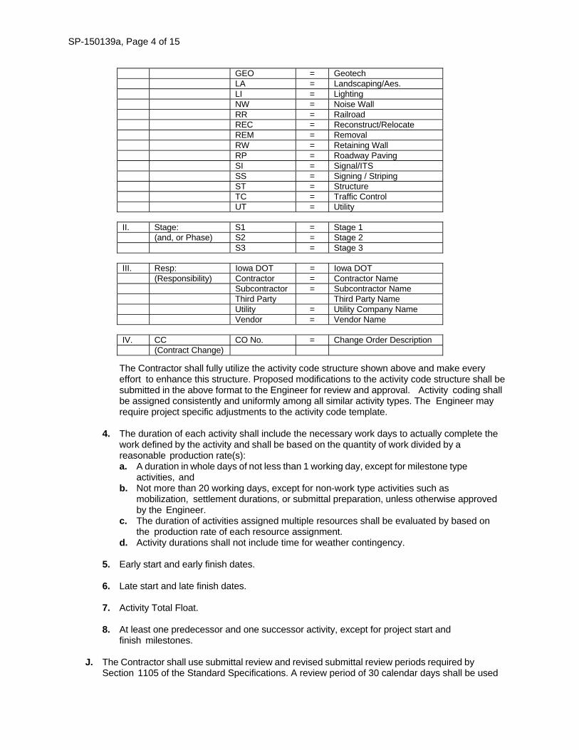
SP-150139a, Page 4 of 15
GEO = Geotech LA = Landscaping/Aes. LI = Lighting NW = Noise Wall RR = Railroad REC = Reconstruct/Relocate REM = Removal RW = Retaining Wall RP = Roadway Paving SI = Signal/ITS SS = Signing / Striping ST = Structure TC = Traffic Control UT = Utility
II. Stage: S1 = Stage 1
(and, or Phase) S2 = Stage 2 S3 = Stage 3
III. Resp: Iowa DOT = Iowa DOT
(Responsibility) Contractor = Contractor Name Subcontractor = Subcontractor Name Third Party Third Party Name Utility = Utility Company Name Vendor = Vendor Name
IV. CC CO No. = Change Order Description
(Contract Change)
The Contractor shall fully utilize the activity code structure shown above and make every effort to enhance this structure. Proposed modifications to the activity code structure shall be submitted in the above format to the Engineer for review and approval. Activity coding shall be assigned consistently and uniformly among all similar activity types. The Engineer may require project specific adjustments to the activity code template.
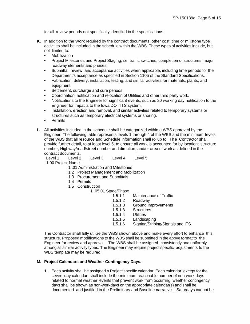
4. The duration of each activity shall include the necessary work days to actually complete the
work defined by the activity and shall be based on the quantity of work divided by a reasonable production rate(s): a. A duration in whole days of not less than 1 working day, except for milestone type
activities, and b. Not more than 20 working days, except for non-work type activities such as
mobilization, settlement durations, or submittal preparation, unless otherwise approved by the Engineer.
c. The duration of activities assigned multiple resources shall be evaluated by based on the production rate of each resource assignment.
d. Activity durations shall not include time for weather contingency.
5. Early start and early finish dates.
6. Late start and late finish dates.
7. Activity Total Float.
8. At least one predecessor and one successor activity, except for project start and finish milestones.
J. The Contractor shall use submittal review and revised submittal review periods required by Section 1105 of the Standard Specifications. A review period of 30 calendar days shall be used
SP-150139a, Page 5 of 15
for all review periods not specifically identified in the specifications.
K. In addition to the Work required by the contract documents, other cost, time or millstone type activities shall be included in the schedule within the WBS. These types of activities include, but not limited to: • Mobilization • Project Milestones and Project Staging, i.e. traffic switches, completion of structures, major
roadway elements and phases. • Submittal, review, and acceptance activities when applicable, including time periods for the
Department’s acceptance as specified in Section 1105 of the Standard Specifications. • Fabrication, delivery, installation, testing, and similar activities for materials, plants, and
equipment. • Settlement, surcharge and cure periods. • Coordination, notification and relocation of Utilities and other third party work. • Notifications to the Engineer for significant events, such as 20 working day notification to the
Engineer for impacts to the Iowa DOT ITS system. • Installation, erection and removal, and similar activities related to temporary systems or
structures such as temporary electrical systems or shoring. • Permits
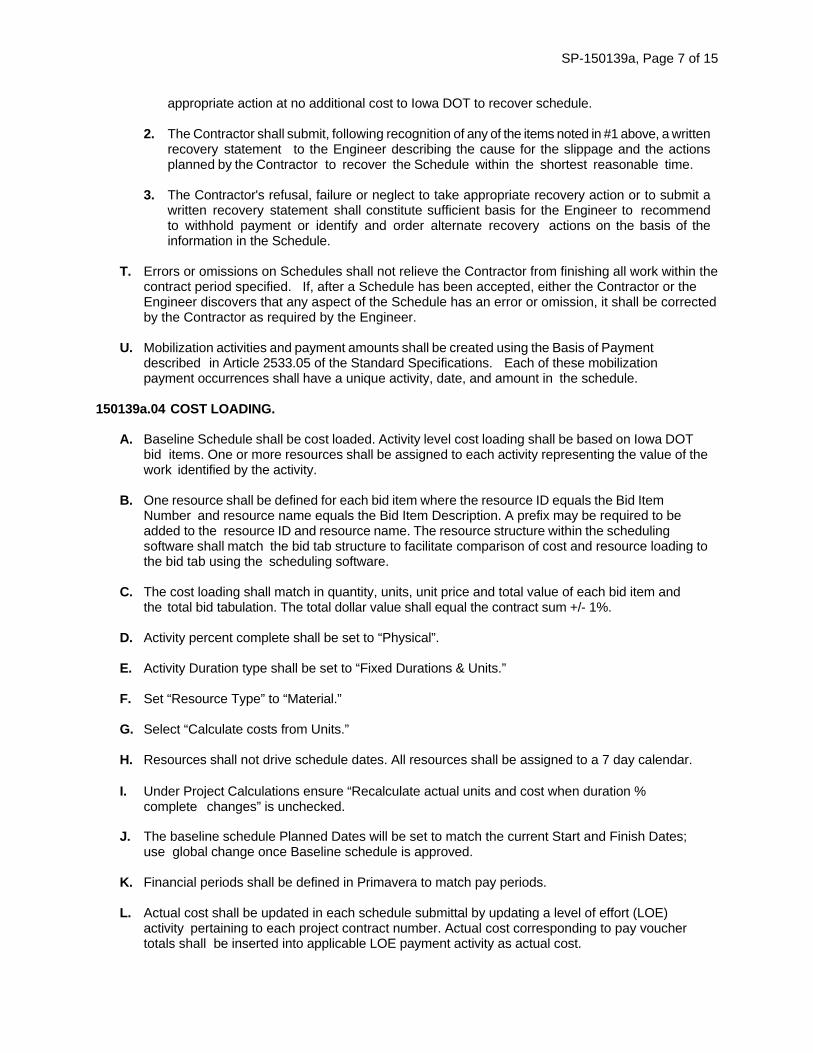
L. All activities included in the schedule shall be categorized within a WBS approved by the
Engineer. The following table represents levels 1 through 4 of the WBS and the minimum levels of the WBS that all resource and Schedule information shall rollup to. The Contractor shall provide further detail, to at least level 5, to ensure all work is accounted for by location; structure number, Highway/road/street number and direction, and/or area of work as defined in the contract documents. Level 1 Level 2 Level 3 Level 4 Level 5 1.00 Project Name
1 .01 Administration and Milestones 1.2 Project Management and Mobilization 1.3 Procurement and Submittals 1.4 Permits 1.5 Construction
1 .05.01 Stage/Phase 1.5.1.1 Maintenance of Traffic 1.5.1.2 Roadway 1.5.1.3 Ground Improvements 1.5.1.3 Structures 1.5.1.4 Utilities 1.5.1.5 Landscaping 1.5.1.6 Signing/Striping/Signals and ITS
The Contractor shall fully utilize the WBS shown above and make every effort to enhance this structure. Proposed modifications to the WBS shall be submitted in the above format to the Engineer for review and approval. The WBS shall be assigned consistently and uniformly among all similar activity types. The Engineer may require project specific adjustments to the WBS template may be required.
M. Project Calendars and Weather Contingency Days.
1. Each activity shall be assigned a Project specific calendar. Each calendar, except for the
seven day calendar, shall include the minimum reasonable number of non-work days related to normal weather events that prevent work from occurring; weather contingency days shall be shown as non-workdays on the appropriate calendar(s) and shall be documented and justified in the Preliminary and Baseline narrative. Saturdays cannot be

SP-150139a, Page 6 of 15
used as a weather contingency work day if a 5 day work week is planned, and Sundays cannot be used as a weather contingency work day if a 6 day work week is planned. The estimated number of weather contingency days shall not be the basis for additional time compensation in the event the number of weather contingency days is exceeded. The number of weather contingency days is subject to the Engineers approval.
2. Calendars shall be updated monthly in the scheduling software with actual days worked and days not worked prior to submittal of an updated Schedule.
3. The number of work related calendars shall be minimized to prevent the distortion of total float, However, calendars specific to a particular type work, such as earthwork, structures, paving, etc. shall be utilized to address seasonal weather limitations based on the type of work. Calendars shall be assigned consistently and uniformly among all similar activities.
N. Schedule submittals shall utilize Project ID and Project Naming conventions approved by
the Engineer.
O. Schedules shall not include or utilize negative lag durations, open ended activities, float suppression techniques or date constraints which are not contractual. The Schedule shall not include positive lag durations, unspecified milestones, and unreasonable logic ties. Sequestering of total float through the manipulation of calendars, extending activity durations, logic ties or sequences is prohibited. Multiple relationships with the same predecessor or successor and reverse logic conditions are prohibited. Redundant logic shall be removed from the schedule.
P. The “Level Resources,” “Apply Actual,” “Update Progress,” “Auto Compute Actuals” or similar functions shall not be used to automatically update the schedule. The schedule shall be updated manually with actual information.
Q. The Contractor shall illustrate, through submittal of a time impact analysis, the effects resulting from any changes which are being negotiated between the Engineer and the Contractor. The Contractor shall prepare a time impact analysis to determine the effect of the change in conformance with the provisions in Article SP-120326.06 SP-150139a.06, D, Time Impact Analysis. Approved time extensions shall be included in the next Schedule update. Changes that do not affect the controlling operation on the longest path will not be considered as the basis for a time adjustment.
R. Use of Float.
1. Total Float and Contract Float are not for the exclusive benefit of the Contractor or IOWA DOT, but is an expiring resource available to the Project, to accommodate changes in the Work, or to mitigate the effect of events which may delay performance or completion of all or part of the Work within the Contract Time. Contract time extensions will be granted only to the extent that delays or disruptions to affected work paths in the Schedule in effect at the time of delay or disruption exceed total float.
2. The use of float suppression techniques are expressly prohibited. The use of any techniques solely for the purpose of suppressing float will be cause for rejection of Schedule submittal.
S. Schedule Recovery.
1. Unless otherwise directed in writing by the Engineer, whenever the schedule includes negative
float, critical items of construction fall behind the planned Schedule or when items which were not critical become critical the Contractor shall promptly notify the Engineer and undertake
SP-150139a, Page 7 of 15
appropriate action at no additional cost to Iowa DOT to recover schedule.
2. The Contractor shall submit, following recognition of any of the items noted in #1 above, a written recovery statement to the Engineer describing the cause for the slippage and the actions planned by the Contractor to recover the Schedule within the shortest reasonable time.
3. The Contractor's refusal, failure or neglect to take appropriate recovery action or to submit a written recovery statement shall constitute sufficient basis for the Engineer to recommend to withhold payment or identify and order alternate recovery actions on the basis of the information in the Schedule.
T. Errors or omissions on Schedules shall not relieve the Contractor from finishing all work within the
contract period specified. If, after a Schedule has been accepted, either the Contractor or the Engineer discovers that any aspect of the Schedule has an error or omission, it shall be corrected by the Contractor as required by the Engineer.
U. Mobilization activities and payment amounts shall be created using the Basis of Payment
described in Article 2533.05 of the Standard Specifications. Each of these mobilization payment occurrences shall have a unique activity, date, and amount in the schedule.
150139a.04 COST LOADING.
A. Baseline Schedule shall be cost loaded. Activity level cost loading shall be based on Iowa DOT bid items. One or more resources shall be assigned to each activity representing the value of the work identified by the activity.
B. One resource shall be defined for each bid item where the resource ID equals the Bid Item Number and resource name equals the Bid Item Description. A prefix may be required to be added to the resource ID and resource name. The resource structure within the scheduling software shall match the bid tab structure to facilitate comparison of cost and resource loading to the bid tab using the scheduling software.
C. The cost loading shall match in quantity, units, unit price and total value of each bid item and the total bid tabulation. The total dollar value shall equal the contract sum +/- 1%.
D. Activity percent complete shall be set to “Physical”.
E. Activity Duration type shall be set to “Fixed Durations & Units.”
F. Set “Resource Type” to “Material.”
G. Select “Calculate costs from Units.”
H. Resources shall not drive schedule dates. All resources shall be assigned to a 7 day calendar.
I. Under Project Calculations ensure “Recalculate actual units and cost when duration % complete changes” is unchecked.
J. The baseline schedule Planned Dates will be set to match the current Start and Finish Dates; use global change once Baseline schedule is approved.
K. Financial periods shall be defined in Primavera to match pay periods.
L. Actual cost shall be updated in each schedule submittal by updating a level of effort (LOE)
activity pertaining to each project contract number. Actual cost corresponding to pay voucher totals shall be inserted into applicable LOE payment activity as actual cost.

SP-150139a, Page 8 of 15
M. Create a resource per LOE payment activity representing voucher payments. Payment resource
to have an assigned price of $1/unit.
N. Actual cost data paid from Iowa DOT pay vouchers shall be saved to the corresponding pay period within the financial period using Primavera’s “Store Period Performance” function.
O. Update cost and resource loaded activities in the schedule based on “Physical % Complete” only, actual cost information is placed in LOE activities.
150139a.05 SCHEDULING CONFERENCE.
A. The Contractor shall schedule and the Engineer will conduct a scheduling conference with the Contractor's project manager and scheduler within 15 calendar days of Receipt of signed contract. At this meeting the Engineer will review the requirements of the special provisions with the Contractor.
B. Items to be submitted by the Contractor, 2 working days before the scheduling conference, include, but are not limited to: • Preliminary Baseline Schedule that complies with the requirements of these special provisions.
The Preliminary Baseline Schedule shall include the activities and sequence of planned operations for the first 120 days of work after Receipt of signed contract and lesser detail for the remainder of the project. The Contractor should be prepared to discuss the proposed work plan and Schedule methodology that comply with the requirements of these special provisions. The schedule shall be submitted electronically in pdf and xer formats.
• List of Activity Codes. • WBS Structure. • Narrative report index. • Graphical reports (time-scaled resource bar charts). • Two Week Detail Schedule.
C. Items to be reviewed include, but are not limited to:
• Review the resume, experience, and qualifications of the proposed Scheduler. • Review of Narrative and report formats. • Review utility, railroad and other third party requirements and schedules. • Review submittal requirements and procedures. • Review time required to review submittals and resubmittals. • Review requirements for tests and inspections. • Review and finalize a list of construction activities to be included in the Schedule. • Review of cost loading. • Review Activity Codes and WBS structure. • Review procedures for updating the Schedule. • Review proposed modifications to the activity ID, activity code and work breakdown structure. • Review other requirements of the specifications regarding Scheduling that are not
specifically listed above.
The Engineer will review the Preliminary Baseline Schedule, proposed modifications, sample reports and other submittals and provide comments or required Baseline Schedule changes to the Contractor for implementation.
150139a.06 SUBMITTAL OF A CPM SCHEDULE.
A. Baseline Schedule Submittals.
1. Beginning the week following the Scheduling Conference, the Contractor and the
SP-150139a, Page 9 of 15
Contractor’s Scheduler shall meet with the Engineer to review Baseline Schedule development and resolve issues identified by the Engineer’s review of the submittals provided at the Scheduling Conference. The Baseline Schedule review meetings will continue to be held every 14 calendar days, unless determined otherwise by the Engineer, until the Baseline Schedule is accepted by the Engineer. The contractor shall submit a revised Baseline schedule 2 working days prior to the Baseline schedule review meetings.
2. The Contractor shall submit to the Engineer an acceptable Baseline Schedule prior to the start of construction activities, but no later than 45 calendar days from receipt of signed contract. Failure to provide an acceptable baseline schedule within 45 calendar days of Receipt of signed contract will result in enforcement of Non-Compliance provisions within this specification.
3. The Baseline Schedule shall include the entire scope of work and how the Contractor plans to complete all Work contracted. The Baseline Schedule shall clearly show the activities that define the critical path. Multiple critical paths and near-critical paths shall be minimized by minimizing the number of predecessors and successor relationships between activities, illogical or redundant logic. A total of not more than 30% of the Baseline Schedule activities shall be critical or near critical, unless otherwise authorized by the Engineer.
4. The Baseline Schedule shall start and finish all work within the contract time(s) established in the contract documents, including but not limited to project start, project finish, intermediate contract periods and milestones, closure limitations, etc. Unless directed otherwise by the Engineer, the Baseline Schedule shall use a data date set to the projects late start date and shall not include progress or as-built updates. The Baseline Schedule shall not include negative float or utilize any other prohibited scheduling technique.
B. Contract Schedule Update Submittals.
1. Schedule updates shall be submitted each calendar month with a data date matching the
progress through date of the first, or last, pay request of each month unless directed otherwise by the Engineer. The first schedule update shall be submitted as prescribed the first month following acceptance of the baseline schedule. Each monthly update shall be submitted within 5 working days of the schedule’s data date. Progress meetings shall be scheduled by the Contractor to correspond with the schedule submittals to review progress with the Engineer.
2. Schedule updates shall include all elements defined for the Baseline Schedule except that a Schedule shall include progress, and as-built updates and updated actual units and cost for each activity, etc.
3. Each Schedule shall show the status of work actually completed up to the data date and the work remaining to be performed as planned. The CPM Schedule diagram shall accurately reflect “as-built” information for each activity shown on previous schedules, including, but not limited to, actual start dates (discounting early starts not representative of true as-built conditions), remaining days of work, percent complete, and actual finish dates (when the activities were completed so that dependent work could proceed) and actual resource utilization. Schedule calendars shall be updated to show actual days worked and days not worked.
4. Schedule updates shall accurately represent all planning changes, adjustments, or updates in the sequencing and timing of work remaining to ensure that the Schedule stays current with the Contractor's plan for performing and furnishing work remaining. If the Schedule submittal indicates slippage or delayed progress, the Contractor shall include a schedule recovery statement.
SP-150139a, Page 10 of 15
5. The Contractor may propose modifications by adding or deleting activities or changing activity descriptions, durations or logic that do not (1) alter the critical path(s) or near critical path(s) or (2) extend the scheduled completion date compared to that shown on the current accepted Schedule and (3) do not disrupt the integrity or comparative relationship between the Baseline and Schedules. The Contractor shall p r o v i d e w r i t t e n r e a s o n s i n the update for any changes to Schedule or planned work. The Engineer shall review the justification for changes and either accept or reject the proposed modifications.
6. If any proposed changes to the schedule or planned work will result in (1), (2) or (3) above, then the Contractor shall submit a time impact analysis as described herein.
7. The Contractor shall incorporate planning revisions, which have been agreed upon in Contract Changes ordered since the last revision. Those revisions shall conform to the sequencing and time of performance requirements of the applicable instrument. These types of revisions shall be included in the Schedule when reconciling extensions in Contract Time.
8. If work is performed out of sequence, the Contractor shall implement logic changes to allow the out of sequence work to proceed. The use of negative lag shall not be permitted.
C. Two Week Detail Schedule.
1. The Contractor shall prepare and submit a detailed 2 week schedule to the Engineer each
bi-weekly until all work is completed. The Two Week Detail Schedule consist of the following:
2. Hand or computer generated bar chart schedule which spans a forward looking, rolling period of at least 14 calendar days from the date of submittal.
3. Updated and submitted to the Engineer on a be-weekly basis on the date at a time specified by
the Engineer.
4. Based on the accepted Schedule and provide a greater breakdown of the Schedule activities; activities for excavation, forming, placing rebar, pouring, stripping backfilling, etc., for example.
5. Specifically reference the accepted Schedule activity ID numbers and define subsequent specific daily operations at each specific location for all work activities scheduled to be performed during the 2 week period.
6. Developed to a level of detail acceptable to the Engineer.
D. Time Impact Analysis.
1. The Contractor shall submit a written TIA to the Engineer with each request for an adjustment of Contract time, when an accepted or anticipated change may impact the critical path or Contract progress or when directed by the Engineer. The Contractor shall take all steps necessary to mitigate the effects to cost and, or time resulting from impacts caused by delay regardless of who is found responsible for the delay.
2. The TIA shall illustrate the impacts of each change or delay on the current scheduled completion date or internal milestone, as appropriate. The analysis shall use the accepted Schedule that has the closest data date prior to the event. If the Engineer determines that the accepted Schedule used does not appropriately represent the conditions prior to the event, the accepted Schedule shall be updated to the day before the event being analyzed. The TIA shall include an impact schedule developed from incorporating the event into the accepted Schedule by adding or deleting activities, or by changing durations or logic of existing activities. If the impact schedule shows that incorporating the event modifies the
SP-150139a, Page 11 of 15
critical path and scheduled completion date of the accepted Schedule, the difference between scheduled completion dates of the two schedules may be considered for an adjustment of Contract time. The Engineer may construct and utilize an appropriate project schedule or other recognized method to determine adjustments in Contract time until the Contractor provides the TIA.
3. The Contractor shall submit a TIA in duplicate within 15 calendar days of receiving a request for a TIA from the Engineer. The Contractor shall allow the Engineer 15 calendar days after receipt to accepted or reject the submitted TIA. All accepted TIA schedule changes shall be shown on the next updated Schedule.
4. If a TIA submitted by the Contractor is rejected by the Engineer, the Contractor shall meet with the Engineer to discuss and resolve issues related to the TIA. The Contractor shall only show actual as-built work, not unaccepted changes related to the TIA, in subsequent updated Schedules. If agreement is reached at a later date, accepted TIA schedule changes shall be shown on the next update Schedule.
5. A time impact analysis shall consist of one or all of the steps listed below: a. Step 1. Establish the status of the project before the impact using the most
recent approved Schedule prior to the impact occurrence. b. Step 2. Predict the effect of the impact on the most Schedule prior to the impact
occurrence. This requires estimating the duration of the impact and inserting the impact into the schedule update. The Contractor shall demonstrate how the impact was inserted into the schedule using a fragment. This is the presentation of a fragmentary portion of the schedule network showing the added or modified activities and the added or modified relationships. Any other changes made to the schedule including modifications to the calendars or constraints shall be noted.
c. Step 3. Track the effects of the impact on the schedule during its occurrence. Note any changes in sequencing, and mitigation efforts.
d. Step 4. Compare the status of the work prior to the impact (Step 1) to the prediction of the effect of the impact (Step 2), and to the status of the work during and after the effects of the impact are over (Step 3).
E. Extension of Contract Time. 1. The Contractor shall notify the Engineer within 5 days of the time impact.
2. The Engineer may use the results of the Time Impact Analysis to determine the extension to
Contract Time.
3. Delays are defined as follows: An event, action, force, or factor causing work to extend beyond the specified contract time.
4. Time may be granted for excusable non-compensable delays that impact the project schedule’s critical path. Additional compensation will not be granted.
5. Time and monetary compensation may be granted for excusable compensable delays that impact the project schedule’s critical path and the Contractor’s costs.
6. Neither time nor money will be granted for non-excusable delays.
7. Contract adjustment is made as written modification to the contract, when warranted, unless the Contractor does not notify the Engineer according to this article.
8. Types of Delays are as follows: a. Excusable Delay – A delay which impacts the longest path and the completion
dates for proposal milestones or project completion that is beyond the Contractor’s
SP-150139a, Page 12 of 15
control, not the fault or responsibility of the Contractor, or could not have been foreseen by the Contractor, for which a time extension may be granted. 1) Compensable Delay – An excusable delay caused by Department action or inaction,
or under the Department’s control, including delays resulting from extra work orders, differing site conditions, work suspensions caused by conditions beyond the control of the Contractor, lack of site access, and delayed shop drawing approval. The Department may grant additional time and compensation for such compensable delays.
2) Non‐compensable Delay – Unforeseen and unanticipated excusable delay caused by acts of God, acts of the public enemy, fires, floods, epidemics, quarantine restrictions, strikes, freight embargoes, unusually severe weather, or delays not the fault of the Contractor or Department. The Department will not grant additional monetary compensation for such delays.
3) Concurrent Delay – A non‐compensable delay that occurs when both the Contractor and the Department independently delay work on longest path activities during approximately the same time period.
b. Non-excusable Delay – A delay that was within the Contractor’s control, was the fault or responsibility of the Contractor, or could have reasonably been foreseen by the Contractor and for which there is no monetary compensation or time extension. Examples of such delay-causing events are normal weather or the failure by the Contractor to assign sufficient resources to the work.
E F. Submittal Requirements.
1. The Contractor shall provide the following items with each schedule submittal;
preliminary, baseline, update, time impact, or revised schedule submittal in electronic format: a. Schedule plot which includes all activities organized by WBS in PDF format. b. Schedule plot of the longest path in PDF format. c. An export of all schedule data in XER format compatible with Primavera Project Manager
Version P8.2 d. Narrative Report
2. Schedule plots shall conform to the following:
a. Include the following columns in the following order: Activity ID, Activity Name, Original Durations, Remaining Duration, Early Start, Early Finish, Total Float, Budgeted Cost, Actual Cost This Period, Actual Cost to Date.
b. Include a title block, schedule name, run date, data date and a timeline on each page. c. Sorted by Early Start.
3. The narrative report shall be organized and tabbed in the following sequence and include all
applicable and appropriate supporting documentation including, but not limited to: a. Contractor's transmittal letter. b. Narrative description supporting the approach to the Work outlined in the Contract
Schedule, i n c l u d i n g reasons for the sequencing of Work, problem areas, unusual conditions, restrictions regarding labor, equipment or material, use of multiple shifts, specified overtime or work at times other than regular days, potential conflicts, and other items that may affect the schedule and how they may be resolved.
c. Narrative description of the general status of the Project including Work completed during the period, Work planned to be completed during the next reporting period, current total float and calculated percent complete.
d. Narrative description of the difference between previously planned Work and the actual Work performed.
SP-150139a, Page 13 of 15
e. The working days per week, number of shifts per day, number of hours per shift, the holidays to be observed, and how the schedule accommodates adverse weather days for each month or activity.
f. Planned Production rates with justification of rates above or below typical. g. A listing of activity durations exceeding the 20 working days with justification thereof. h. A list of activity relationships with lags with justification for use of the lag. i. A list of constrained activities with a justification for use of the constraint. j. Activities requiring coordination with the Department and/or 3rd parties (i.e. Utilities,
adjacent contractors, etc) k. Schedule changes - A listing of all changes, and a narrative description of the reason or
justification for the changes and the resulting affects or impact of the changes: • Added, deleted or modified activities and activity descriptions. • Added, deleted or modified date constraints. • Added, deleted or modified lags. • Added, deleted or modified logic. • Added, deleted or modified calendars. • Modified activity durations. • Significant changes in float.
l. Narrative description of the current longest path. m. Comparative analysis of changes to the longest path with the previous schedule
submittal, including identification of and justification for the cause of the changes. n. Changes to the scheduled completion date since the last Schedule submittal
including identification of and justification for the cause of the change. o. Current and anticipated delays:
• Cause of delay. • Impact of delay on other activities, milestones and completion dates. • Corrective action and schedule adjustments to correct the delay.
p. Pending items and status thereof: • Permits • Contract changes • Time adjustments • Time Impact Analysis
q. Cost information: • Include a listing and justification for adjustments to cost loading. • Comparison of schedule cost loading and current pay application.
r. Additional Information as requested by the Engineer. s. A statement certifying the schedule submittal is based on factual, accurate
information which represents true planned and as-built conditions accompanied with the signature of the Project Manager and Scheduler.
Schedule submittals will be considered complete when all documents and data have been provided as described above to the satisfaction of the Engineer.
150139a.07 SCHEDULE REVIEWS.
A. The Engineer’s review will be for conformance with the Contract Time and those sequences of Work indicated in or required by the Contract Documents, to record Early and Late Dates for Milestones, to identify the Contractor's use of Float, to compare as-built data, and for conformance with the requirements of this Special Provision and other information given in the Contract Documents which may have a bearing on the Schedule. The Engineer’s review may extend to the accuracy of other matters dealt with by the Schedule, including, but not limited to, whether work is omitted, activity durations are reasonable, the level of labor, materials and equipment, the Contractor's means, methods, techniques, procedures, or sequences of construction, or whether the sequences and timing for work remaining are practicable, the correctness of all which shall remain the sole responsibility of the Contractor. The Engineers
SP-150139a, Page 14 of 15
review may also extend to the technical acceptability of the Schedule submittal.
B. The Contractor shall allow 7 working days for the Engineer's review after each Schedule update and all support data are submitted, except that the review period shall not start until the previous month's Schedule update submittal is accepted. Schedules that are not accepted or rejected within the review period will be considered not accepted by the Engineer.
C. The Engineer's review and acceptance of Schedules shall not waive any Contract requirements and shall not relieve the Contractor of any obligation or responsibility for submitting complete and accurate information. Schedules that are not approved, rejected, or returned revise and resubmit shall be corrected by the Contractor and resubmitted to the Engineer within 5 working days of notification.
D. When reviewed by the Engineer, one copy of each Schedule submittal will be returned to the Contractor as either "Revise and Resubmit" or "Acceptable". Submittals found “Acceptable” will represent the most-current Schedule as of the date of the submittal. Neither the Engineer’s review of a schedule, nor the Engineer’s statement of "Acceptable", will relieve the Contractor from responsibility for complying with the Contract Specifications, Contract Time requirements and completing all work required by the Contract Documents. Failure by the Contractor to include any element of the Work required by the Contract does not relieve the Contractor from its responsibility to complete the work, or to complete the omitted Work within the Contract Time(s). “Acceptance” of the Schedule submittals by the Engineer does not attest to the validity of assumptions, production rates, activities, relationships, sequences, resource allocations or any other aspect of the Schedule submittal. Schedule submittals determined to be “Acceptable” by the Engineer may be reviewed again for “Acceptability” at a later date, if deemed necessary by the Engineer. The Contractor remains obligated to correct schedule issues identified during future reviews by the Engineer.
E. The Contractor shall make appropriate adjustments or corrections in a Schedule submittal returned to him as "Revise and Resubmit", and shall respond with the required copies of a full, revised Schedule revision submittal within 5 working days of receipt of the Engineer’s comments. Once the Contractor's Schedule submittal, or resubmittal, is returned to the Contractor as '”Acceptable", it shall represent the most current approved Schedule for the Work as of the date of the submittal, and it shall be the basis for the monitoring of the Contractor's performance and progress.
F. The most-current Schedule will be the basis for (a) the monitoring of the Contractor's progress against Milestone and Contract Times, and (b) the evaluation and reconciliation of extensions in Contract Time, if and when a Contract Time is indeed extended.
G. All schedules shall be in accordance with the Contract Time requirements of the Contract. Nothing contained in this Section shall relieve the Contractor from compliance with the Contract Time.
H. The Engineer’s acceptance does not warrant or imply accuracy or Iowa DOT agreement with production rates or other factors used to prepare the Schedule.
I. The Engineer may monitor the Contractor’s production rates, project personnel and equipment usage for comparison with the Contract Schedule at his/her discretion.
J. Should the Contractor submit a claim with reference to the Schedule as part of the claim rationale, Iowa DOT’s prior acceptance of the Schedule will not be considered as acceptance of the assumed production rates and other factors used in the development of the Schedule.
K. If the Engineer elects to review an early-completion schedule, the time between the scheduled completion date and the completion date associated with the Contract Time is considered Float.
SP-150139a, Page 15 of 15
L. The review of a portion of the Schedule or an incomplete Schedule submittal shall not indicate
acceptance of the entire Schedule. 150139.08 PROJECT MANAGEMENT When the Supplemental Specifications for Project Management are applied, the following requirements shall be active:
A. Communication with the Engineer: The Project Manager shall schedule and participate in a bi-weekly schedule and quantity rectification meeting with the Engineer. This meeting will occur at the beginning of each week of voucher issuance.
B. Documentation of Item Progress: Schedule Activity ID shall be included for all item quantity
records and measurement. 150139.09 150139a.08 NONCOMPLIANCE.
A. Non-Compliance – Iowa DOT will remedy the nonconformance by retaining an amount equal to 100% of the total estimated value of the work performed during each period in which the Contractor fails, refuses or neglects to satisfy the requirements of this specification, or the Contract Schedule submittals precludes a proper evaluation by the Engineer, or the Contract Schedule submittals preclude an “Acceptable” determination, or if the Contractor fails to conform said submittals within the submittal time requirements herein. Retention due to this non-conformance shall be in addition to all other retentions provided for under the Contract. The retention withheld for Non-Compliance will be released for payment on the next pay estimate for partial payment following the date the Engineer determines compliance has been achieved and, or the submittal(s) are found Acceptable.
B. Progress & Performance – If the project falls 15 calendar days behind schedule, the Engineer may take steps specified in Article 1108.02., I of the Standard Specifications to suspend the Contractor’s bidding qualifications. If the Contractor fails to take action within 14 calendar days, the Engineer may take steps specified in Article 1108.10 of the Standard Specifications to declare the contract in default.
150139.10 150139a.09 METHOD OF MEASUREMENT AND BASIS OF PAYMENT.
A. Lump Sum price for Progress Scheduling shall be full compensation for all costs for complying with this special provision.
B. Progress payments for this item will be made at the same rate as the percent of work
completed.
POTTAWATTAMIE COUNTY PROJECT NUMBER IM-NHS-080-1(393)0--03-78 SHEET NUMBER C.1FILE NO. ENGLISH DESIGN TEAM Abrams/Stanley Consultants11/9/2016 11:03:51 AM 5549 \\mus-fs2\Mus-Projects-2\iadot\23900\23900-28(CBIS E-1 West)\78-0801-393 - Pottawattamie\Electrical\Tabs\78-0801-393c01.xlsm ADDENDUM
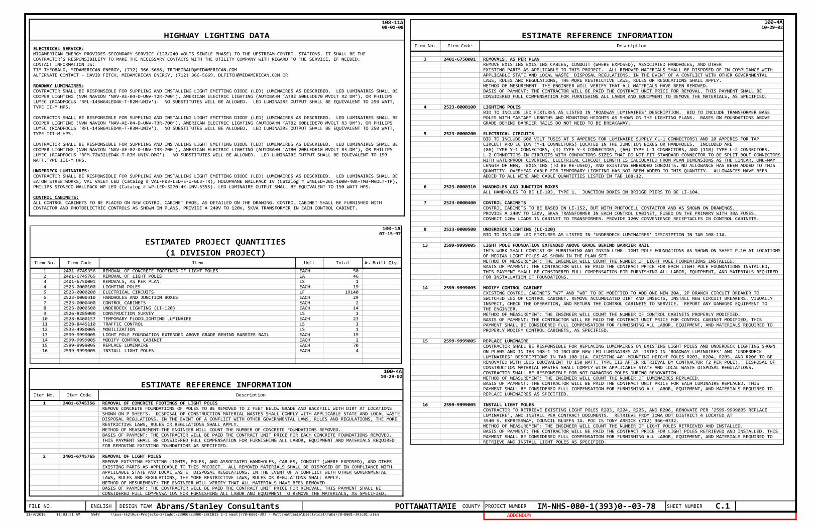
1 2401-6745356 REMOVAL OF CONCRETE FOOTINGS OF LIGHT POLES EACH 502 2401-6745765 REMOVAL OF LIGHT POLES EA 463 2401-6750001 REMOVALS, AS PER PLAN LS 14 2523-0000100 LIGHTING POLES EACH 195 2523-0000200 ELECTRICAL CIRCUITS LF 191406 2523-0000310 HANDHOLES AND JUNCTION BOXES EACH 297 2523-0000400 CONTROL CABINETS EACH 28 2523-0000500 UNDERDECK LIGHTING (LI-120) EACH 149 2526-8285000 CONSTRUCTION SURVEY LS 110 2528-8400157 TEMPORARY FLOODLIGHTING LUMINAIRE EACH 2311 2528-8445110 TRAFFIC CONTROL LS 112 2533-4980005 MOBILIZATION LS 113 2599-9999005 LIGHT POLE FOUNDATION EXTENDED ABOVE GRADE BEHIND BARRIER RAIL EACH 1914 2599-9999005 MODIFY CONTROL CABINET EACH 215 2599-9999005 REPLACE LUMINAIRE EACH 7016 2599-9999005 INSTALL LIGHT POLES EACH 4
100-1A07-15-97
ESTIMATED PROJECT QUANTITIES
(1 DIVISION PROJECT)Item No. Item Code Item Unit Total As Built Qty.
108-11A08-01-08
ELECTRICAL SERVICE:MIDAMERICAN ENERGY PROVIDES SECONDARY SERVICE (120/240 VOLTS SINGLE PHASE) TO THE UPSTREAM CONTROL STATIONS. IT SHALL BE THE CONTRACTOR'S RESPONSIBILITY TO MAKE THE NECESSARY CONTACTS WITH THE UTILITY COMPANY WITH REGARD TO THE SERVICE, IF NEEDED.CONTACT INFORMATION IS: TIM THEOBALD, MIDAMERICAN ENERGY, (712) 366-5668, [email protected] CONTACT - DAVID FITCH, MIDAMERICAN ENERGY, (712) 366-5669, [email protected] OR
ROADWAY LUMINAIRES:CONTRACTOR SHALL BE RESPONSIBLE FOR SUPPLING AND INSTALLING LIGHT EMITTING DIODE (LED) LUMINAIRES AS DESCRIBED. LED LUMINAIRES SHALL BECOOPER LIGHTING (NVN NAVION ‘NAV-AE-04-D-UNV-T2R-700’), AMERICAN ELECTRIC LIGHTING (AUTOBAHN ‘ATB2 60BLEDE70 MVOLT R2 DM’), OR PHILIPSLUMEC (ROADFOCUS ‘RFL-145W64LED4K-T-R2M-UNIV’). NO SUBSTITUTES WILL BE ALLOWED. LED LUMINAIRE OUTPUT SHALL BE EQUIVALENT TO 250 WATT,TYPE II-M HPS.
CONTRACTOR SHALL BE RESPONSIBLE FOR SUPPLING AND INSTALLING LIGHT EMITTING DIODE (LED) LUMINAIRES AS DESCRIBED. LED LUMINAIRES SHALL BECOOPER LIGHTING (NVN NAVION ‘NAV-AE-04-D-UNV-T3R-700’), AMERICAN ELECTRIC LIGHTING (AUTOBAHN ‘ATB2 60BLEDE70 MVOLT R3 DM’), OR PHILIPSLUMEC (ROADFOCUS ‘RFL-145W64LED4K-T-R3M-UNIV’). NO SUBSTITUTES WILL BE ALLOWED. LED LUMINAIRE OUTPUT SHALL BE EQUIVALENT TO 250 WATT,TYPE III-M HPS.
CONTRACTOR SHALL BE RESPONSIBLE FOR SUPPLING AND INSTALLING LIGHT EMITTING DIODE (LED) LUMINAIRES AS DESCRIBED. LED LUMINAIRES SHALL BECOOPER LIGHTING (NVN NAVION ‘NAV-AE-02-D-UNV-T3R-700’), AMERICAN ELECTRIC LIGHTING (AUTOBAHN ‘ATB0 20BLEDE10 MVOLT R3 DM’), OR PHILIPSLUMEC (ROADFOCUS ‘RFM-72W32LED4K-T-R3M-UNIV-DMG’). NO SUBSTITUTES WILL BE ALLOWED. LED LUMINAIRE OUTPUT SHALL BE EQUIVALENT TO 150WATT,TYPE III-M HPS.
UNDERDECK LUMINAIRES:CONTRACTOR SHALL BE RESPONSIBLE FOR SUPPLING AND INSTALLING LIGHT EMITTING DIODE (LED) LUMINAIRES AS DESCRIBED. LED LUMINAIRES SHALL BEEATON STREETWORKS, VAL VALET LED (Catalog # VAL-F03-LED-E-U-GL3-TR), HOLOPHANE WALLPACK IV (Catalog # W4GLED-20C-1000-40K-TM3-MVOLT-TP), PHILIPS STONECO WALLPACK WP LED (Catalog # WP-LED-3270-4K-UNV-535S). LED LUMINAIRE OUTPUT SHALL BE EQUIVALENT TO 150 WATT HPS.
CONTROL CABINETS:ALL CONTROL CABINETS TO BE PLACED ON NEW CONTROL CABINET PADS, AS DETAILED ON THE DRAWING. CONTROL CABINET SHALL BE FURNISHED WITHCONTACTOR AND PHOTOELECTRIC CONTROLS AS SHOWN ON PLANS. PROVIDE A 240V TO 120V, 5KVA TRANSFORMER IN EACH CONTROL CABINET.
HIGHWAY LIGHTING DATA
1 2401-6745356 REMOVAL OF CONCRETE FOOTINGS OF LIGHT POLESREMOVE CONCRETE FOUNDATIONS OF POLES TO BE REMOVED TO 2 FEET BELOW GRADE AND BACKFILL WITH DIRT AT LOCATIONSSHOWN ON P SHEETS. DISPOSAL OF CONSTRUCTION MATERIAL WASTES SHALL COMPLY WITH APPLICABLE STATE AND LOCAL WASTE DISPOSAL REGULATIONS. IN THE EVENT OF A CONFLICT WITH OTHER GOVERNMENTAL LAWS, RULES AND REGULATIONS, THE MORE RESTRICTIVE LAWS, RULES OR REGULATIONS SHALL APPLY.METHOD OF MEASUREMENT:THE ENGINEER WILL COUNT THE NUMBER OF CONCRETE FOUNDATIONS REMOVED.BASIS OF PAYMENT: THE CONTRACTOR WILL BE PAID THE CONTRACT UNIT PRICE FOR EACH CONCRETE FOUNDATIONS REMOVED. THIS PAYMENT SHALL BE CONSIDERED FULL COMPENSATION FOR FURNISHING ALL LABOR, EQUIPMENT AND MATERIALS REQUIRED FOR REMOVING EXISTING FOUNDATIONS AS SPECIFIED.
2 2401-6745765 REMOVAL OF LIGHT POLESREMOVE EXISTING EXISTING LIGHTS, POLES, AND ASSOCIATED HANDHOLES, CABLES, CONDUIT (WHERE EXPOSED), AND OTHEREXISTING PARTS AS APPLICABLE TO THIS PROJECT. ALL REMOVED MATERIALS SHALL BE DISPOSED OF IN COMPLIANCE WITHAPPLICABLE STATE AND LOCAL WASTE DISPOSAL REGULATIONS. IN THE EVENT OF A CONFLICT WITH OTHER GOVERNMENTALLAWS, RULES AND REGULATIONS, THE MORE RESTRICTIVE LAWS, RULES OR REGULATIONS SHALL APPLY.METHOD OF MESUREMENT: THE ENGINEER WILL VERIFY THAT ALL MATERIALS HAVE BEEN REMOVED. BASIS OF PAYMENT: THE CONTRACTOR WILL BE PAID THE CONTRACT UNIT PRICE FOR REMOVAL. THIS PAYMENT SHALL BE CONSIDERED FULL COMPENSATION FOR FURNISHING ALL LABOR AND EQUIPMENT TO REMOVE THE MATERIALS, AS SPECIFIED.
100-4A10-29-02
ESTIMATE REFERENCE INFORMATIONItem No. Item Code Description
3 2401-6750001 REMOVALS, AS PER PLANREMOVE EXISTING EXISTING CABLES, CONDUIT (WHERE EXPOSED), ASSOCIATED HANDHOLES, AND OTHEREXISTING PARTS AS APPLICABLE TO THIS PROJECT. ALL REMOVED MATERIALS SHALL BE DISPOSED OF IN COMPLIANCE WITHAPPLICABLE STATE AND LOCAL WASTE DISPOSAL REGULATIONS. IN THE EVENT OF A CONFLICT WITH OTHER GOVERNMENTALLAWS, RULES AND REGULATIONS, THE MORE RESTRICTIVE LAWS, RULES OR REGULATIONS SHALL APPLY.METHOD OF MESUREMENT: THE ENGINEER WILL VERIFY THAT ALL MATERIALS HAVE BEEN REMOVED. BASIS OF PAYMENT: THE CONTRACTOR WILL BE PAID THE CONTRACT UNIT PRICE FOR REMOVAL. THIS PAYMENT SHALL BE CONSIDERED FULL COMPENSATION FOR FURNISHING ALL LABOR AND EQUIPMENT TO REMOVE THE MATERIALS, AS SPECIFIED.
4 2523-0000100 LIGHTING POLESBID TO INCLUDE LED FIXTURES AS LISTED IN ‘ROADWAY LUMINAIRES’ DESCRIPTION. BID TO INCLUDE TRANSFORMER BASE POLES WITH MASTARM LENGTHS AND MOUNTING HEIGHTS AS SHOWN ON THE LIGHTING PLANS. BASES ON FOUNDATIONS ABOVEGRADE BEHIND BARRIER RAILS DO NOT NEED TO BE BREAKAWAY.
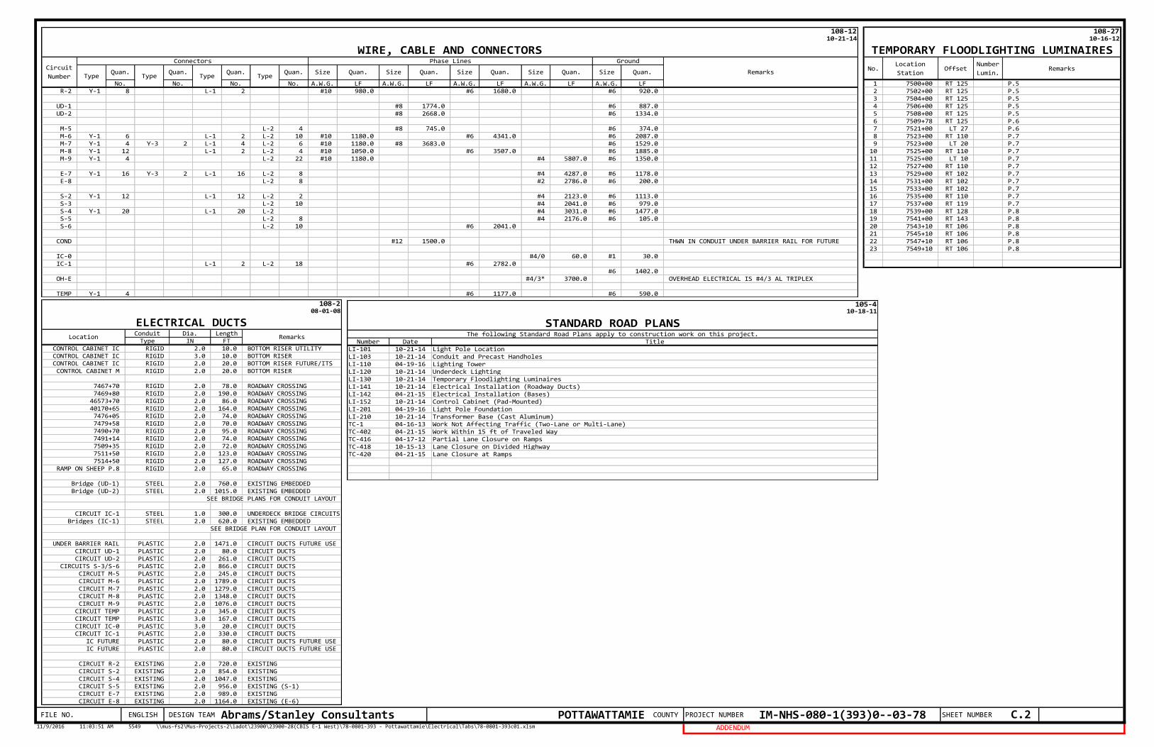
5 2523-0000200 ELECTRICAL CIRCUITS BID TO INCLUDE 600 VOLT FUSES AT 5 AMPERES FOR LUMINAIRE SUPPLY (L-1 CONNECTORS) AND 20 AMPERES FOR TAP CIRCUIT PROTECTION (Y-1 CONNECTORS) LOCATED IN THE JUNCTION BOXES OR HANDHOLES. INCLUDED ARE (86) TYPE Y-1 CONNECTORS, (4) TYPE Y-3 CONNECTORS, (60) TYPE L-1 CONNECTORS, AND (110) TYPE L-2 CONNECTORS.L-2 CONNECTORS IN CIRCUITS WITH CONDUCTORS SIZES THAT DO NOT FIT STANDARD CONNECTOR TO BE SPLIT BOLT CONNECTORS WITH WATERPROOF COVERING. ELECTRICAL CIRCUIT LENGTH IS CALCULATED FROM PLAN DIMENSIONS AS THE LINEAR, ONE-WAYLENGTH OF NEW, EXISTING (TO BE RE-USED), AND EXISTING EMBEDDED CONDUITS. NO ALLOWANCE HAS BEEN ADDED TO THISQUANTITY. OVERHEAD CABLE FOR TEMPORARY LIGHTING HAS NOT BEEN ADDED TO THIS QUANTITY. ALLOWANCES HAVE BEENADDED TO ALL WIRE AND CABLE QUANTITIES LISTED IN TAB 108-12.
6 2523-0000310 HANDHOLES AND JUNCTION BOXESALL HANDHOLES TO BE LI-103, TYPE 1. JUNCTION BOXES ON BRIDGE PIERS TO BE LI-104.
7 2523-0000400 CONTROL CABINETSCONTROL CABINETS TO BE BASED ON LI-152, BUT WITH PHOTOCELL CONTACTOR AND AS SHOWN ON DRAWINGS.PROVIDE A 240V TO 120V, 5KVA TRANSFORMER IN EACH CONTROL CABINET, FUSED ON THE PRIMARY WITH 30A FUSES.CONNECT 120V LOADS IN CABINET TO TRANSFORMER. PROVIDE 120V CONVENIENCE RECEPTACLES IN CONTROL CABINETS.
8 2523-0000500 UNDERDECK LIGHTING (LI-120) BID TO INCLUDE LED FIXTURES AS LISTED IN ‘UNDERDECK LUMINAIRES’ DESCRIPTION IN TAB 108-11A.
13 2599-9999005 LIGHT POLE FOUNDATION EXTENDED ABOVE GRADE BEHIND BARRIER RAILTHIS WORK SHALL CONSIST OF FURNISHING AND INSTALLING LIGHT POLE FOUNDATIONS AS SHOWN ON SHEET P.10 AT LOCATIONS OF MEDIAN LIGHT POLES AS SHOWN IN THE PLAN SET.METHOD OF MEASUREMENT: THE ENGINEER WILL COUNT THE NUMBER OF LIGHT POLE FOUNDATIONS INSTALLED.BASIS OF PAYMENT: THE CONTRACTOR WILL BE PAID THE CONTRACT PRICE FOR EACH LIGHT POLE FOUNDATIONS INSTALLED, THIS PAYMENT SHALL BE CONSIDERED FULL COMPENSATION FOR FURNISHING ALL LABOR, EQUIPMENT, AND MATERIALS REQUIRED FOR INSTALLATION OF FOUNDATIONS.
14 2599-9999005 MODIFY CONTROL CABINETEXISTING CONTROL CABINETS "W7" AND "W8" TO BE MODIFIED TO ADD ONE NEW 20A, 2P BRANCH CIRCUIT BREAKER TO SWITCHED LEG OF CONTROL CABINET. REMOVE ACCUMULATED DIRT AND INSECTS, INSTALL NEW CIRCUIT BREAKERS. VISUALLY INSPECT, CHECK THE OPERATION, AND RETURN THE CONTROL CABINETS TO SERVICE. REPORT ANY DAMAGED EQUIPMENT TOTHE ENGINEER.METHOD OF MEASUREMENT: THE ENGINEER WILL COUNT THE NUMBER OF CONTROL CABINETS PROPERLY MODIFIED.BASIS OF PAYMENT: THE CONTRACTOR WILL BE PAID THE CONTRACT UNIT PRICE FOR CONTROL CABINET MODIFIED, THIS PAYMENT SHALL BE CONSIDERED FULL COMPENSATION FOR FURNISHING ALL LABOR, EQUIPMENT, AND MATERIALS REQUIRED TO PROPERLY MODIFY CONTROL CABINETS, AS SPECIFIED.
15 2599-9999005 REPLACE LUMINAIRECONTRACTOR SHALL BE RESPONSIBLE FOR REPLACING LUMINAIRES ON EXISTING LIGHT POLES AND UNDERDECK LIGHTING SHOWNON PLANS AND IN TAB 108-1 TO INCLUDE NEW LED LUMINAIRES AS LISTED IN 'ROADWAY LUMINAIRES' AND 'UNDERDECK LUMINAIRES' DESCRIPTIONS IN TAB 108-11A. EXISTING 40' MOUNTING HEIGHT POLES R203, R204, R205, AND R206 TO BE RENOVATED WITH LEDS EQUIVALENT TO 150 WATT, TYPE III AFTER RETRIEVAL BY CONTRACTOR (2 PER POLE). DISPOSAL OF CONSTRUCTION MATERIAL WASTES SHALL COMPLY WITH APPLICABLE STATE AND LOCAL WASTE DISPOSAL REGULATIONS. CONTRACTOR SHALL BE RESPONSIBLE FOR NOT DAMAGING POLES DURING RENOVATION.METHOD OF MEASUREMENT: THE ENGINEER WILL COUNT THE NUMBER OF LUMINAIRES REPLACED.BASIS OF PAYMENT: THE CONTRACTOR WILL BE PAID THE CONTRACT UNIT PRICE FOR EACH LUMINAIRE REPLACED. THISPAYMENT SHALL BE CONSIDERED FULL COMPENSATION FOR FURNISHING ALL LABOR, EQUIPMENT, AND MATERIALS REQUIRED TOREPLACE LUMINAIRES AS SPECIFIED.
16 2599-9999005 INSTALL LIGHT POLESCONTRACTOR TO RETRIEVE EXISTING LIGHT POLES R203, R204, R205, AND R206, RENOVATE PER '2599-9999005 REPLACELUMINAIRE', AND INSTALL PER CONTRACT DOCUMENTS. RETRIEVE FROM IOWA DOT DISTRICT 4 LOCATED AT 3540 S. EXPRESSWAY, COUNCIL BLUFFS IA. POC IS TONY ARRICK (712) 366-0332.METHOD OF MEASUREMENT: THE ENGINEER WILL COUNT THE NUMBER OF LIGHT POLES RETRIEVED AND INSTALLED.BASIS OF PAYMENT: THE CONTRACTOR WILL BE PAID THE CONTRACT PRICE FOR LIGHT POLES RETRIEVED AND INSTALLED. THIS PAYMENT SHALL BE CONSIDERED FULL COMPENSATION FOR FURNISHING ALL LABOR, EQUIPMENT, AND MATERIALS REQUIRED TORETRIEVE AND INSTALL LIGHT POLES AS SPECIFIED.
100-4A10-29-02
ESTIMATE REFERENCE INFORMATIONItem No. Item Code Description
POTTAWATTAMIE COUNTY PROJECT NUMBER IM-NHS-080-1(393)0--03-7811/9/2016 11:03:51 AM 5549 \\mus-fs2\Mus-Projects-2\iadot\23900\23900-28(CBIS E-1 West)\78-0801-393 - Pottawattamie\Electrical\Tabs\78-0801-393c01.xlsm ADDENDUM
SHEET NUMBERFILE NO. ENGLISH DESIGN TEAM Abrams/Stanley Consultants C.2
1 7500+00 RT 125 P.52 7502+00 RT 125 P.53 7504+00 RT 125 P.54 7506+00 RT 125 P.55 7508+00 RT 125 P.56 7509+78 RT 125 P.67 7521+00 LT 27 P.68 7523+00 RT 110 P.79 7523+00 LT 20 P.710 7525+00 RT 110 P.711 7525+00 LT 10 P.712 7527+00 RT 110 P.713 7529+00 RT 102 P.714 7531+00 RT 102 P.715 7533+00 RT 102 P.716 7535+00 RT 110 P.717 7537+00 RT 119 P.718 7539+00 RT 128 P.819 7541+00 RT 143 P.820 7543+10 RT 106 P.821 7545+10 RT 106 P.822 7547+10 RT 106 P.823 7549+10 RT 106 P.8
108-2710-16-12
TEMPORARY FLOODLIGHTING LUMINAIRES
No.Location
StationOffset
Number
Lumin.Remarks
No. No. No. No. A.W.G. LF A.W.G. LF A.W.G. LF A.W.G. LF A.W.G. LFR-2 Y-1 8 L-1 2 #10 980.0 #6 1680.0 #6 920.0
UD-1 #8 1774.0 #6 887.0UD-2 #8 2668.0 #6 1334.0
M-5 L-2 4 #8 745.0 #6 374.0M-6 Y-1 6 L-1 2 L-2 10 #10 1180.0 #6 4341.0 #6 2087.0M-7 Y-1 4 Y-3 2 L-1 4 L-2 6 #10 1180.0 #8 3683.0 #6 1529.0M-8 Y-1 12 L-1 2 L-2 4 #10 1050.0 #6 3507.0 #6 1885.0M-9 Y-1 4 L-2 22 #10 1180.0 #4 5807.0 #6 1350.0
E-7 Y-1 16 Y-3 2 L-1 16 L-2 8 #4 4287.0 #6 1178.0E-8 L-2 8 #2 2786.0 #6 200.0
S-2 Y-1 12 L-1 12 L-2 2 #4 2123.0 #6 1113.0S-3 L-2 10 #4 2041.0 #6 979.0S-4 Y-1 20 L-1 20 L-2 #4 3031.0 #6 1477.0S-5 L-2 8 #4 2176.0 #6 105.0S-6 L-2 10 #6 2041.0
COND #12 1500.0 THWN IN CONDUIT UNDER BARRIER RAIL FOR FUTURE
IC-0 #4/0 60.0 #1 30.0IC-1 L-1 2 L-2 18 #6 2782.0
#6 1402.0OH-E #4/3* 3700.0 OVERHEAD ELECTRICAL IS #4/3 AL TRIPLEX
TEMP Y-1 4 #6 1177.0 #6 590.0
Quan.
108-1210-21-14
WIRE, CABLE AND CONNECTORS
Circuit
Number
Connectors Phase Lines Ground
RemarksType
Quan.Type
Quan.Type
Quan.Type
Size Quan. Size Quan.Size Quan. Size Quan. Size Quan.
Conduit Dia. LengthType IN FT
CONTROL CABINET IC RIGID 2.0 10.0 BOTTOM RISER UTILITYCONTROL CABINET IC RIGID 3.0 10.0 BOTTOM RISERCONTROL CABINET IC RIGID 2.0 20.0 BOTTOM RISER FUTURE/ITSCONTROL CABINET M RIGID 2.0 20.0 BOTTOM RISER
7467+70 RIGID 2.0 78.0 ROADWAY CROSSING7469+80 RIGID 2.0 190.0 ROADWAY CROSSING46573+70 RIGID 2.0 86.0 ROADWAY CROSSING40170+65 RIGID 2.0 164.0 ROADWAY CROSSING7476+05 RIGID 2.0 74.0 ROADWAY CROSSING7479+58 RIGID 2.0 70.0 ROADWAY CROSSING7490+70 RIGID 2.0 95.0 ROADWAY CROSSING7491+14 RIGID 2.0 74.0 ROADWAY CROSSING7509+35 RIGID 2.0 72.0 ROADWAY CROSSING7511+50 RIGID 2.0 123.0 ROADWAY CROSSING7514+50 RIGID 2.0 127.0 ROADWAY CROSSING
RAMP ON SHEEP P.8 RIGID 2.0 65.0 ROADWAY CROSSING
Bridge (UD-1) STEEL 2.0 760.0 EXISTING EMBEDDEDBridge (UD-2) STEEL 2.0 1015.0 EXISTING EMBEDDED
SEE BRIDGE PLANS FOR CONDUIT LAYOUT
CIRCUIT IC-1 STEEL 1.0 300.0 UNDERDECK BRIDGE CIRCUITSBridges (IC-1) STEEL 2.0 620.0 EXISTING EMBEDDED
SEE BRIDGE PLAN FOR CONDUIT LAYOUT
UNDER BARRIER RAIL PLASTIC 2.0 1471.0 CIRCUIT DUCTS FUTURE USECIRCUIT UD-1 PLASTIC 2.0 80.0 CIRCUIT DUCTSCIRCUIT UD-2 PLASTIC 2.0 261.0 CIRCUIT DUCTS
CIRCUITS S-3/S-6 PLASTIC 2.0 866.0 CIRCUIT DUCTSCIRCUIT M-5 PLASTIC 2.0 245.0 CIRCUIT DUCTSCIRCUIT M-6 PLASTIC 2.0 1789.0 CIRCUIT DUCTSCIRCUIT M-7 PLASTIC 2.0 1279.0 CIRCUIT DUCTSCIRCUIT M-8 PLASTIC 2.0 1348.0 CIRCUIT DUCTSCIRCUIT M-9 PLASTIC 2.0 1076.0 CIRCUIT DUCTSCIRCUIT TEMP PLASTIC 2.0 345.0 CIRCUIT DUCTSCIRCUIT TEMP PLASTIC 3.0 167.0 CIRCUIT DUCTSCIRCUIT IC-0 PLASTIC 3.0 20.0 CIRCUIT DUCTSCIRCUIT IC-1 PLASTIC 2.0 330.0 CIRCUIT DUCTS
IC FUTURE PLASTIC 2.0 80.0 CIRCUIT DUCTS FUTURE USEIC FUTURE PLASTIC 2.0 80.0 CIRCUIT DUCTS FUTURE USE
CIRCUIT R-2 EXISTING 2.0 720.0 EXISTINGCIRCUIT S-2 EXISTING 2.0 854.0 EXISTINGCIRCUIT S-4 EXISTING 2.0 1047.0 EXISTINGCIRCUIT S-5 EXISTING 2.0 956.0 EXISTING (S-1)CIRCUIT E-7 EXISTING 2.0 989.0 EXISTINGCIRCUIT E-8 EXISTING 2.0 1164.0 EXISTING (E-6)
108-208-01-08
ELECTRICAL DUCTSLocation Remarks
Number Date TitleLI-101 10-21-14 Light Pole LocationLI-103 10-21-14 Conduit and Precast HandholesLI-110 04-19-16 Lighting TowerLI-120 10-21-14 Underdeck LightingLI-130 10-21-14 Temporary Floodlighting LuminairesLI-141 10-21-14 Electrical Installation (Roadway Ducts)LI-142 04-21-15 Electrical Installation (Bases)LI-152 10-21-14 Control Cabinet (Pad-Mounted)LI-201 04-19-16 Light Pole FoundationLI-210 10-21-14 Transformer Base (Cast Aluminum)TC-1 04-16-13 Work Not Affecting Traffic (Two-Lane or Multi-Lane)TC-402 04-21-15 Work Within 15 ft of Traveled WayTC-416 04-17-12 Partial Lane Closure on RampsTC-418 10-15-13 Lane Closure on Divided HighwayTC-420 04-21-15 Lane Closure at Ramps
105-410-18-11
STANDARD ROAD PLANSThe following Standard Road Plans apply to construction work on this project.
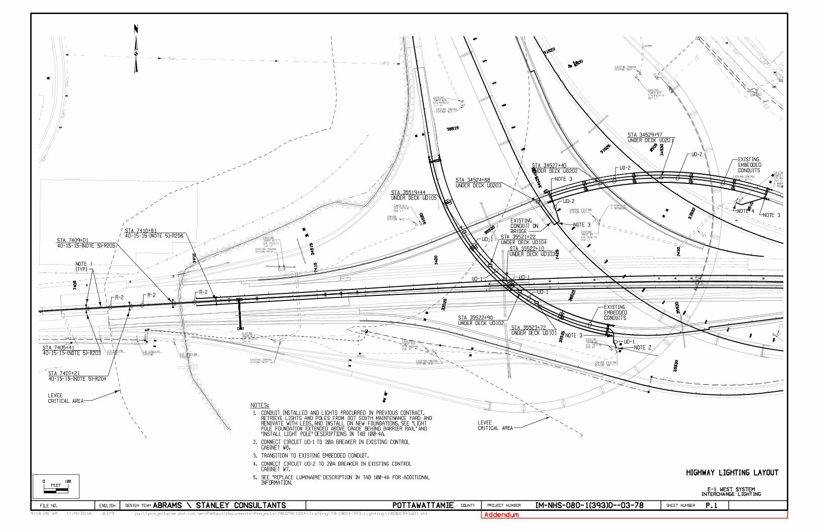
P.1
O O 100
FEET
HIGHWAY LIGHTING LAYOUT
1.
NOTES:
2.CABINET W8.CONNECT CIRCUIT UD-1 TO 20A BREAKER IN EXISTING CONTROL
3. TRANSITION TO EXISTING EMBEDDED CONDUIT.
CABINET W7.CONNECT CIRCUIT UD-2 TO 20A BREAKER IN EXISTING CONTROL 4.
NOTE 3
NOTE 3
INTERCHANGE LIGHTING
E-1 WEST SYSTEM
5.
Addendum
INFORMATION.SEE "REPLACE LUMINAIRE" DESCRIPTION IN TAB 100-4A FOR ADDITIONAL
"INSTALL LIGHT POLE" DESCRIPTIONS IN TAB 100-4A.POLE FOUNDATION EXTENDED ABOVE GRADE BEHIND BARRIER RAIL" AND RENOVATE WITH LEDS, AND INSTALL ON NEW FOUNDATIONS. SEE "LIGHT RETRIEVE LIGHTS AND POLES FROM DOT SOUTH MAINTENANCE YARD AND CONDUIT INSTALLED AND LIGHTS PROCURRED IN PREVIOUS CONTRACT.
6179 pw:\\projectwise.dot.int.lan:PWMain\Documents\Projects\7802901004\TrafEng\78-0801-393_Lighting\78080393p01.sht
DESIGN TEAM PROJECT NUMBER SHEET NUMBER COUNTY
9:18:28 AM
ENGLISH
11/9/2016
FILE NO. ABRAMS \ STANLEY CONSULTANTS IM-NHS-080-1(393)0--03-78POTTAWATTAMIE
CRITICAL AREA
LEVEE
CRITICAL AREA
LEVEE
CONDUITS
EMBEDDED
EXISTING
NOTE 3
NOTE 2
UD-1
UD-1
UD-1
UD-1
UD-1
CONDUITS
EMBEDDED
EXISTING
UD-2
UD-2
UD-2
NOTE 4
BRIDGE
CONDUIT ON
EXISTINGSTATION "W11"CONTROL
269' LT
STA 7419+47
TOWER W11
HH#10
HH#55
R-3
HH#2
E 981066.89
N 458412.97
(3")E-1
EXISTING
STA 7405+90
EXISTING
STA 37507+45
EXISTING
STA 37509+00
STATION "W12"EXISTING CONTROL
179' RT
STA 7413+14
TOWER W12
EXISTING
STATION "W13"EXISTING CONTROL
116' LT
STA 7413+71
TOWER W13
EXISTING
256' RT
STA 7419+48
TOWER W10
EXISTING
STATION "W10"EXISTING CONTROL
STATION "W15"EXISTING CONTROL
111' RT
STA 9499+17
TOWER W15
EXISTING
STATION "W9"CONTROL EXISTING
258' LT
STA 7426+74
TOWER W9
EXISTING
CABINET "W7"
EXISTING CONTROL
E 981650.36
N 458495.58
104' LT
STA 8509+45
TOWER W7
EXISTING
STATION "W5"CONTROL EXISTING
276' RT
STA 7427+16
TOWER W8
EXISTING
STATION "W8"CONTROL EXISTING
STATION "W14"EXISTING CONTROL
257' LT
STA 8502+15
TOWER W14
EXISTING
40-15-15-(NOTE 5)-R206
STA 7410+81
40-15-15-(NOTE 5)-R205
STA 7409+01
40-15-15-(NOTE 5)-R203
STA 7405+41
40-15-15-(NOTE 5)-R204
STA 7407+21
R-2R-2
R-2
UNDER DECK UD105
STA 35519+44
UNDER DECK UD104
STA 35521+22
UNDER DECK UD103
STA 35522+10
UNDER DECK UD102
STA 35522+90
UNDER DECK UD101
STA 35523+72
UNDER DECK UD203
STA 34524+68
UNDER DECK UD202
STA 34527+40
UNDER DECK UD201
STA 34529+97
NOTE 3
(TYP)
NOTE 1
9497
9498
9499
9500
9501
9502
9503
9504
9505
9506
9507
9508
9509
9510
9511
9512
9513
9514
9515
9516
3152
0
31525
31530
32520
32525
32530
34525
34535
34515
34520
34525
34530
35515
35520
35525
35530
8500
8505
8510
7405
7415 7420 7425
7430
7410
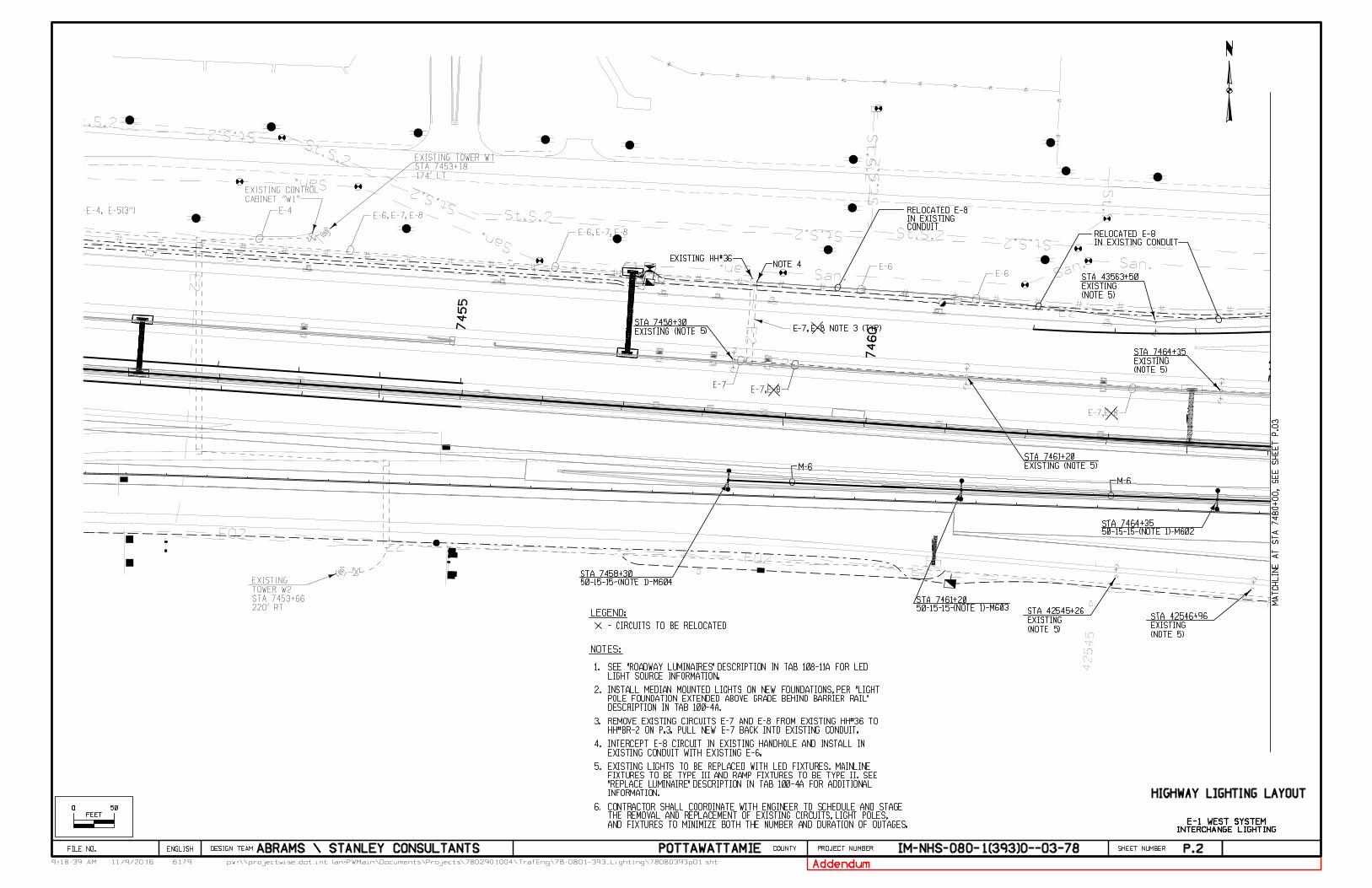
P.2
HIGHWAY LIGHTING LAYOUT
MA
TC
HLI
NE
AT
ST
A 7480
+00,
SE
E
SH
EE
T
P.03
LEGEND:
- CIRCUITS TO BE RELOCATED
INTERCHANGE LIGHTING
E-1 WEST SYSTEM
O O 50
FEET
LIGHT SOURCE INFORMATION.SEE "ROADWAY LUMINAIRES" DESCRIPTION IN TAB 108-11A FOR LED1.
NOTES:
2.
DESCRIPTION IN TAB 100-4A.POLE FOUNDATION EXTENDED ABOVE GRADE BEHIND BARRIER RAIL" INSTALL MEDIAN MOUNTED LIGHTS ON NEW FOUNDATIONS, PER "LIGHT
3.HH#BR-2 ON P.3. PULL NEW E-7 BACK INTO EXISTING CONDUIT.REMOVE EXISTING CIRCUITS E-7 AND E-8 FROM EXISTING HH#36 TO
4.EXISTING CONDUIT WITH EXISTING E-6.INTERCEPT E-8 CIRCUIT IN EXISTING HANDHOLE AND INSTALL IN
5.
Addendum
INFORMATION."REPLACE LUMINAIRE" DESCRIPTION IN TAB 100-4A FOR ADDITIONAL FIXTURES TO BE TYPE III AND RAMP FIXTURES TO BE TYPE II. SEE EXISTING LIGHTS TO BE REPLACED WITH LED FIXTURES. MAINLINE
AND FIXTURES TO MINIMIZE BOTH THE NUMBER AND DURATION OF OUTAGES.THE REMOVAL AND REPLACEMENT OF EXISTING CIRCUITS, LIGHT POLES, CONTRACTOR SHALL COORDINATE WITH ENGINEER TO SCHEDULE AND STAGE 6.
61799:18:39 AM pw:\\projectwise.dot.int.lan:PWMain\Documents\Projects\7802901004\TrafEng\78-0801-393_Lighting\78080393p01.sht
DESIGN TEAM PROJECT NUMBER SHEET NUMBER COUNTY
11/9/2016
ENGLISHFILE NO. ABRAMS \ STANLEY CONSULTANTS POTTAWATTAMIE IM-NHS-080-1(393)0--03-78
E-7E-7,E-8
E-7,E-8
E-4, E-5(3")E-6, E-7, E-8
E-6, E-7, E-8
E-7E-7,E-8
E-6E-6
M-6
M-6
E-4
174' LT
STA 7453+18
EXISTING TOWER W1
CABINET "W1"
EXISTING CONTROL
220' RT
STA 7453+66
TOWER W2
EXISTING
50-15-15-(NOTE 1)-M603STA 7461+20
50-15-15-(NOTE 1)-M604STA 7458+30
50-15-15-(NOTE 1)-M602STA 7464+35
NOTE 4
CONDUITIN EXISTINGRELOCATED E-8
IN EXISTING CONDUITRELOCATED E-8
EXISTING (NOTE 5)
STA 7458+30
EXISTING HH#36
(NOTE 5)
EXISTING
STA 43563+50
(NOTE 5)
EXISTING
STA 7464+35
EXISTING (NOTE 5)
STA 7461+20
E-7, E-8 NOTE 3 (TYP)
(NOTE 5)
EXISTING
STA 42545+26
(NOTE 5)
EXISTING
STA 42546+96
42545
7460
7465
7455
P.3
HIGHWAY LIGHTING LAYOUT
MA
TC
HLI
NE
AT
ST
A 7465
+00,
SE
E
SH
EE
T
P.02
LEGEND:
- CIRCUITS TO BE RELOCATED
INTERCHANGE LIGHTING
E-1 WEST SYSTEM
MA
TC
HLI
NE
AT
ST
A 7480
+00,
SE
E
SH
EE
T
P.04
O O 50
FEET
LIGHT SOURCE INFORMATION.SEE "ROADWAY LUMINAIRES" DESCRIPTION IN TAB 108-11A FOR LED1.
NOTES:
2.
DESCRIPTION IN TAB 100-4A.POLE FOUNDATION EXTENDED ABOVE GRADE BEHIND BARRIER RAIL" INSTALL MEDIAN MOUNTED LIGHTS ON NEW FOUNDATIONS, PER "LIGHT
3.
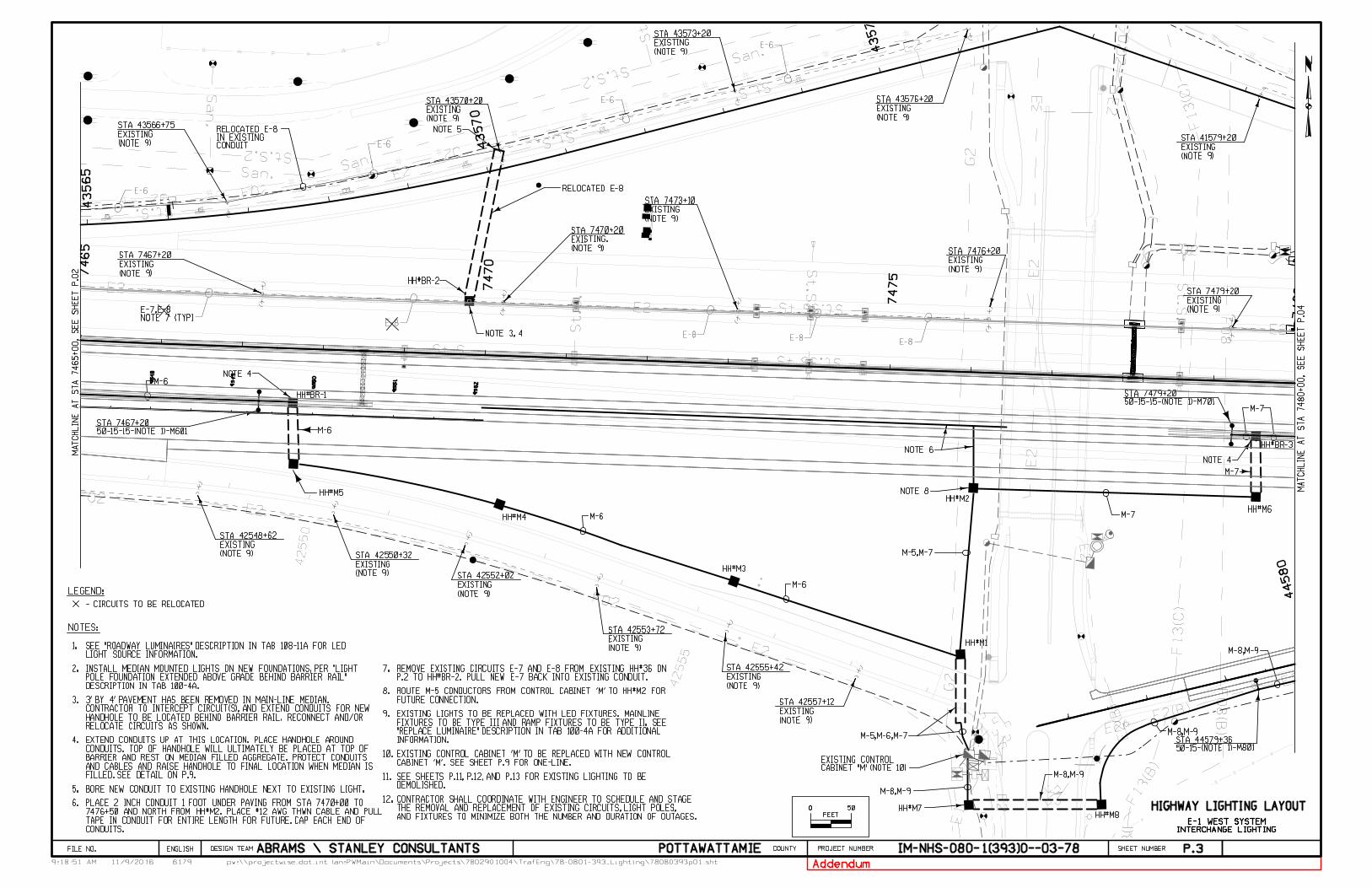
RELOCATE CIRCUITS AS SHOWN.HANDHOLE TO BE LOCATED BEHIND BARRIER RAIL. RECONNECT AND/OR CONTRACTOR TO INTERCEPT CIRCUIT(S), AND EXTEND CONDUITS FOR NEW 3' BY 4' PAVEMENT HAS BEEN REMOVED IN MAIN-LINE MEDIAN.
4.
5. BORE NEW CONDUIT TO EXISTING HANDHOLE NEXT TO EXISTING LIGHT.
FILLED. SEE DETAIL ON P.9.AND CABLES AND RAISE HANDHOLE TO FINAL LOCATION WHEN MEDIAN IS BARRIER AND REST ON MEDIAN FILLED AGGREGATE. PROTECT CONDUITS CONDUITS. TOP OF HANDHOLE WILL ULTIMATELY BE PLACED AT TOP OF EXTEND CONDUITS UP AT THIS LOCATION. PLACE HANDHOLE AROUND
6.
CONDUITS.TAPE IN CONDUIT FOR ENTIRE LENGTH FOR FUTURE. CAP EACH END OF 7476+50 AND NORTH FROM HH#M2. PLACE #12 AWG THWN CABLE AND PULL PLACE 2 INCH CONDUIT 1 FOOT UNDER PAVING FROM STA 7470+00 TO
7.P.2 TO HH#BR-2. PULL NEW E-7 BACK INTO EXISTING CONDUIT.REMOVE EXISTING CIRCUITS E-7 AND E-8 FROM EXISTING HH#36 ON
8.FUTURE CONNECTION.ROUTE M-5 CONDUCTORS FROM CONTROL CABINET 'M' TO HH#M2 FOR
9.
10.CABINET 'M'. SEE SHEET P.9 FOR ONE-LINE.EXISTING CONTROL CABINET 'M' TO BE REPLACED WITH NEW CONTROL
11.DEMOLISHED.SEE SHEETS P.11, P.12, AND P.13 FOR EXISTING LIGHTING TO BE
Addendum
INFORMATION."REPLACE LUMINAIRE" DESCRIPTION IN TAB 100-4A FOR ADDITIONAL FIXTURES TO BE TYPE III AND RAMP FIXTURES TO BE TYPE II. SEE EXISTING LIGHTS TO BE REPLACED WITH LED FIXTURES. MAINLINE
AND FIXTURES TO MINIMIZE BOTH THE NUMBER AND DURATION OF OUTAGES.THE REMOVAL AND REPLACEMENT OF EXISTING CIRCUITS, LIGHT POLES, CONTRACTOR SHALL COORDINATE WITH ENGINEER TO SCHEDULE AND STAGE 12.
61799:18:51 AM pw:\\projectwise.dot.int.lan:PWMain\Documents\Projects\7802901004\TrafEng\78-0801-393_Lighting\78080393p01.sht
DESIGN TEAM PROJECT NUMBER SHEET NUMBER COUNTY
11/9/2016
ENGLISHFILE NO. ABRAMS \ STANLEY CONSULTANTS POTTAWATTAMIE IM-NHS-080-1(393)0--03-78
E-6
E-6
E-6
E-6
E-8E-8 E-8
E-8
M-6
RELOCATED E-8
50-15-15-(NOTE 1)-M601STA 7467+20
50-15-15-(NOTE 1)-M701STA 7479+20
M-6
M-6
NOTE 3, 4
HH#BR-2
HH#M5
HH#M3
HH#M1
HH#M2
M-5,M-6,M-7
M-5,M-7
M-6
M-7
HH#M7HH#M8
M-7
HH#M6
M-7
HH#BR-3
NOTE 4
M-8,M-9
M-8,M-9
M-8,M-9
M-8,M-9
HH#BR-1
CONDUITIN EXISTINGRELOCATED E-8
HH#M4
NOTE 5
NOTE 4
NOTE 6
NOTE 8
CABINET "M" (NOTE 10)EXISTING CONTROL
50-15-(NOTE 1)-M801STA 44579+36
NOTE 7 (TYP)E-7,E-8
(NOTE 9)
EXISTING
STA 7467+20
(NOTE 9)
EXISTING
STA 43566+75
(NOTE 9)
EXISTING
STA 7473+10
(NOTE 9)
EXISTING.
STA 7470+20
(NOTE 9)
EXISTING
STA 7476+20
(NOTE 9)
EXISTING
STA 43576+20
(NOTE 9)
EXISTING
STA 43573+20
(NOTE 9)
EXISTING
STA 7479+20
(NOTE 9)
EXISTING
STA 41579+20
(NOTE 9)
EXISTING
STA 43570+20
42550
42555
(NOTE 9)
EXISTING
STA 42548+62
(NOTE 9)
EXISTING
STA 42550+32
(NOTE 9)
EXISTING
STA 42552+02
(NOTE 9)
EXISTING
STA 42553+72
(NOTE 9)
EXISTING
STA 42555+42
(NOTE 9)
EXISTING
STA 42557+12
9548
9549
9550
9551
9552
7465
7470
7475
7480
44580
43565
43570
43575
P.4
INTERCHANGE LIGHTING
E-1 WEST SYSTEM
HIGHWAY LIGHTING LAYOUT
MA
TC
HLI
NE
AT
ST
A 7480
+00,
SE
E
SH
EE
T
P.03
MA
TC
HLI
NE
AT
ST
A 7493
+00,
SE
E
SH
EE
T
P.05
LEGEND:
- CIRCUITS TO BE RELOCATED
O O 50
FEET
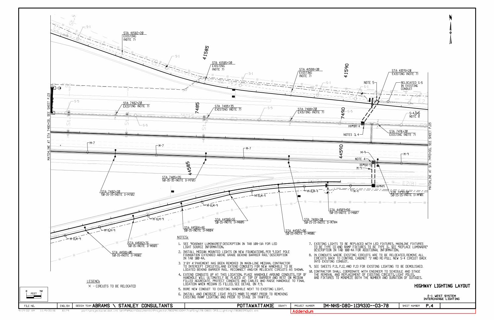
LIGHT SOURCE INFORMATION.SEE "ROADWAY LUMINAIRES" DESCRIPTION IN TAB 108-11A FOR LED1.
NOTES:
2.
3.
4.
5. BORE NEW CONDUIT TO EXISTING HANDHOLE NEXT TO EXISTING LIGHT.
IN TAB 100-4A.FOUNDATION EXTENDED ABOVE GRADE BEHIND BARRIER RAIL" DESCRIPTION INSTALL MEDIAN MOUNTED LIGHTS ON NEW FOUNDATIONS, PER "LIGHT POLE
LOCATED BEHIND BARRIER RAIL. RECONNECT AND/OR RELOCATE CIRCUITS AS SHOWN.TO INTERCEPT CIRCUIT(S), AND EXTEND CONDUITS FOR NEW HANDHOLE TO BE3' BY 4' PAVEMENT HAS BEEN REMOVED IN MAIN-LINE MEDIAN. CONTRACTOR
EXISTING RAMP LIGHTING AND PRIOR TO STAGE 2A TRAFFIC.INSTALL AND ENERGIZE LIGHT POLES M801 TO M807 PRIOR TO REMOVING6.
7.
8.
INTO EXISTING CONDUIT.CIRCUITS BACK TO CONTROL CABINET 'S' AND RE-PULL NEW S-4 CIRCUIT BACKIN CONDUITS WHERE EXISTING CIRCUITS ARE TO BE RELOCATED, REMOVE ALL
9.
LOCATION WHEN MEDIAN IS FILLED. SEE DETAIL ON P.9.FILLED AGGREGATE. PROTECT CONDUITS AND CABLES AND RAISE HANDHOLE TO FINAL HANDHOLE WILL ULTIMATELY BE PLACED AT TOP OF BARRIER AND REST ON MEDIAN EXTEND CONDUITS UP AT THIS LOCATION. PLACE HANDHOLE AROUND CONDUITS. TOP OF
SEE SHEETS P.11, P.12, AND P.13 FOR EXISTING LIGHTING TO BE DEMOLISHED.
Addendum
DESCRIPTION IN TAB 100-4A FOR ADDITIONAL INFORMATION.TO BE TYPE III AND RAMP FIXTURES TO BE TYPE II. SEE "REPLACE LUMINAIRE"EXISTING LIGHTS TO BE REPLACED WITH LED FIXTURES. MAINLINE FIXTURES
AND FIXTURES TO MINIMIZE BOTH THE NUMBER AND DURATION OF OUTAGES.THE REMOVAL AND REPLACEMENT OF EXISTING CIRCUITS, LIGHT POLES, CONTRACTOR SHALL COORDINATE WITH ENGINEER TO SCHEDULE AND STAGE 10.
61799:19:02 AM pw:\\projectwise.dot.int.lan:PWMain\Documents\Projects\7802901004\TrafEng\78-0801-393_Lighting\78080393p01.sht
DESIGN TEAM PROJECT NUMBER SHEET NUMBER COUNTY
11/9/2016
ENGLISHFILE NO. ABRAMS \ STANLEY CONSULTANTS POTTAWATTAMIE IM-NHS-080-1(393)0--03-78
S-1
S-1
S-5
S-1
S-5
S-1
S-1
S-1
S-5
M-7
50-15-15-(NOTE 1)-M702STA 7482+20
50-15-15-(NOTE 1)-M703STA 7485+35
50-15-15-(NOTE 1)-M901STA 7491+20M-8,M-9
M-8,M-9
M-8,M-9
M-8,M-9
M-8,M-9
M-8,M-9
M-9
M-9
M-7M-7
M-9M-9
HH#BR-5
HH#BR-4
NOTES 3, 4
NOTE 4
CONDUITIN EXISTING RELOCATED S-5
HH#M9
NOTE 5
(NOTE 7)
EXISTING
STA 41582+20
(NOTE 7)
EXISTING
STA 41585+20
(NOTE 7)
EXISTING
STA 41588+20
EXISTING (NOTE 7)
STA 41591+20
EXISTING (NOTE 7)
STA 7482+20
EXISTING (NOTE 7)
STA 7485+35
EXISTING (NOTE 7)
STA 7488+20S-5
EXISTING (NOTE 7)
STA 7491+20
NOTE 8
S-4,S-5
50-15-(NOTE 1)-M807STA 44589+56
50-15-(NOTE 1)-M806STA 44587+86
50-15-(NOTE 1)-M805STA 44586+16
50-15-(NOTE 1)-M804STA 44584+46
50-15-(NOTE 1)-M803STA 44582+76
50-15-(NOTE 1)-M802STA 44581+05
50-15-15-(NOTE 1)-M704STA 7488+20
APR42
APR42
APR42
APR42APR42
SOLAR PANEL
7480
7485
7490
44580
44585
44590
41590
41580
41585
P.5
MA
TC
HLI
NE
AT
ST
A 7508
+00,
SE
E
SH
EE
T
P.06
MA
TC
HLI
NE
AT
ST
A 7493
+00,
SE
E
SH
EE
T
P.04
INTERCHANGE LIGHTING
E-1 WEST SYSTEM
HIGHWAY LIGHTING LAYOUT
LEGEND:
- CIRCUITS TO BE RELOCATED
O O 50
FEET
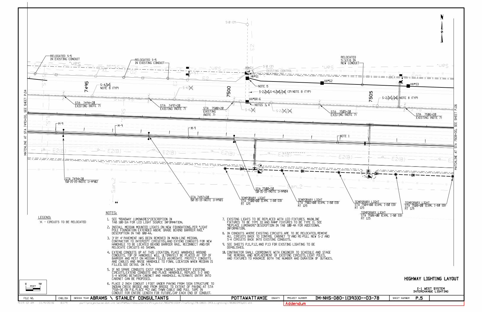
1.
NOTES:
TAB 108-11A FOR LED LIGHT SOURCE INFORMATION.SEE "ROADWAY LUMINAIRES" DESCRIPTION IN
2.
DESCRIPTION IN TAB 100-4A.POLE FOUNDATION EXTENDED ABOVE GRADE BEHIND BARRIER RAIL" INSTALL MEDIAN MOUNTED LIGHTS ON NEW FOUNDATIONS, PER "LIGHT
3.
RELOCATE CIRCUITS AS SHOWN.HANDHOLE TO BE LOCATED BEHIND BARRIER RAIL. RECONNECT AND/OR CONTRACTOR TO INTERCEPT CIRCUIT(S), AND EXTEND CONDUITS FOR NEW 3' BY 4' PAVEMENT HAS BEEN REMOVED IN MAIN-LINE MEDIAN.
4.
5.
CABINET CAN BE PROPOSED.S-4 WIRING BETWEEN CABINET AND HANDHOLE. ALTERNATE ENTRY INTO CIRCUITS, EXTEND CONDUITS AND PLACE HANDHOLE. REPLACE S-2 AND IF NO SPARE CONDUITS EXIST FROM CABINET, INTERCEPT EXISTING
6.
FILLED. SEE DETAIL ON P.9.AND CABLES AND RAISE HANDHOLE TO FINAL LOCATION WHEN MEDIAN IS BARRIER AND REST ON MEDIAN FILLED AGGREGATE. PROTECT CONDUITS CONDUITS. TOP OF HANDHOLE WILL ULTIMATELY BE PLACED AT TOP OF EXTEND CONDUITS UP AT THIS LOCATION. PLACE HANDHOLE AROUND
7.
8.
S-4 CIRCUITS BACK INTO EXISTING CONDUITS.ALL CIRCUITS BACK TO CONTROL CABINET 'S' AND RE-PULL NEW S-2 AND IN CONDUITS WHERE EXISTING CIRCUITS ARE TO BE RELOCATED, REMOVE
9.DEMOLISHED.SEE SHEETS P.11, P.12, AND P.13 FOR EXISTING LIGHTING TO BE
CONDUIT FOR ENTIRE LENGTH FOR FUTURE. CAP EACH END OF CONDUIT.7518+36 ON P.6. PLACE #12 AWG THWN CABLE AND PULL TAPE IN INDIAN CREEK BRIDGE AND FROM BRIDGE TO EXTENT OF PAVING AT STA PLACE 2 INCH CONDUIT 1 FOOT UNDER PAVING FROM SIGN STRUCTURE TO
Addendum
INFORMATION."REPLACE LUMINAIRE" DESCRIPTION IN TAB 100-4A FOR ADDITIONAL FIXTURES TO BE TYPE III AND RAMP FIXTURES TO BE TYPE II. SEE EXISTING LIGHTS TO BE REPLACED WITH LED FIXTURES. MAINLINE
AND FIXTURES TO MINIMIZE BOTH THE NUMBER AND DURATION OF OUTAGES.THE REMOVAL AND REPLACEMENT OF EXISTING CIRCUITS, LIGHT POLES, CONTRACTOR SHALL COORDINATE WITH ENGINEER TO SCHEDULE AND STAGE 10.
61799:19:12 AM pw:\\projectwise.dot.int.lan:PWMain\Documents\Projects\7802901004\TrafEng\78-0801-393_Lighting\78080393p01.sht
DESIGN TEAM PROJECT NUMBER SHEET NUMBER COUNTY
11/9/2016
ENGLISHFILE NO. ABRAMS \ STANLEY CONSULTANTS POTTAWATTAMIE IM-NHS-080-1(393)0--03-78
S-1
S-1
S-4,S-5
S-4,S-5 S-2,S-3,S-6
S-0 (3")
S-0 (3")
NEW CONDUITS-3,S-6 IN RELOCATED
NOTE 1
STATION "S"EXISTING CONTROL
50-15-15-(NOTE 1)-M902STA 7494+20
50-15-15-(NOTE 1)-M903STA 7497+20
50-15-15-(NOTE 1)-M904STA 7500+20
RT 125STA 7500+00 (EXML I-80 EB)TEMPORARY LIGHT
RT 125STA 7502+00 (EXML I-80 EB)TEMPORARY LIGHT
RT 125STA 7504+00 (EXML I-80 EB)TEMPORARY LIGHT
RT 125STA 7506+00 (EXML I-80 EB)TEMPORARY LIGHT
RT 125STA 7508+00 (EXML I-80 EB)TEMPORARY LIGHT
OHOH
OH
OH
M-9M-9
M-9
HH#S1
HH#BR-6
NOTES 3, 4
NOTE 5
IN EXISTING CONDUITRELOCATED S-5
IN EXISTING CONDUITRELOCATED S-5
HH#S2
HH#S3
NOTE 8 (TYP)
S-4,S-5
EXISTING (NOTE 7)
STA 7494+20
EXISTING (NOTE 7)
STA 7497+20
(NOTE 7)
EXISTING
STA 7500+20
S-2,S-3,S-4,S-5,S-6 (3") NOTE 8 (TYP)
EXISTING (NOTE 7)
STA 7503+20
EXISTING (NOTE 7)
STA 7506+20
S-2,S-3,S-6 NOTE 8 (TYP)
DRAWN FROM TOPO QL D
DRAWN IN QL D
DRAWN IN QL D
PRIVATE LIFT STATION
PRIVATE LIFT STATION
PRIVATE LIFT STATION
PRIVATE LIFT STATION
DRAWN IN QL D
APR24
DRAWN FROM TOPO QL D
APR24
DRAINAGE
DRAINAGE
DRAINAGE
DRAINAGE
DRAINAGE
DRAINAGE
DRAINAGE
DRAINAGE
DRAINAGE
DRAINAGE
DRAINAGE
DRAINAGE
7495
7500
7505
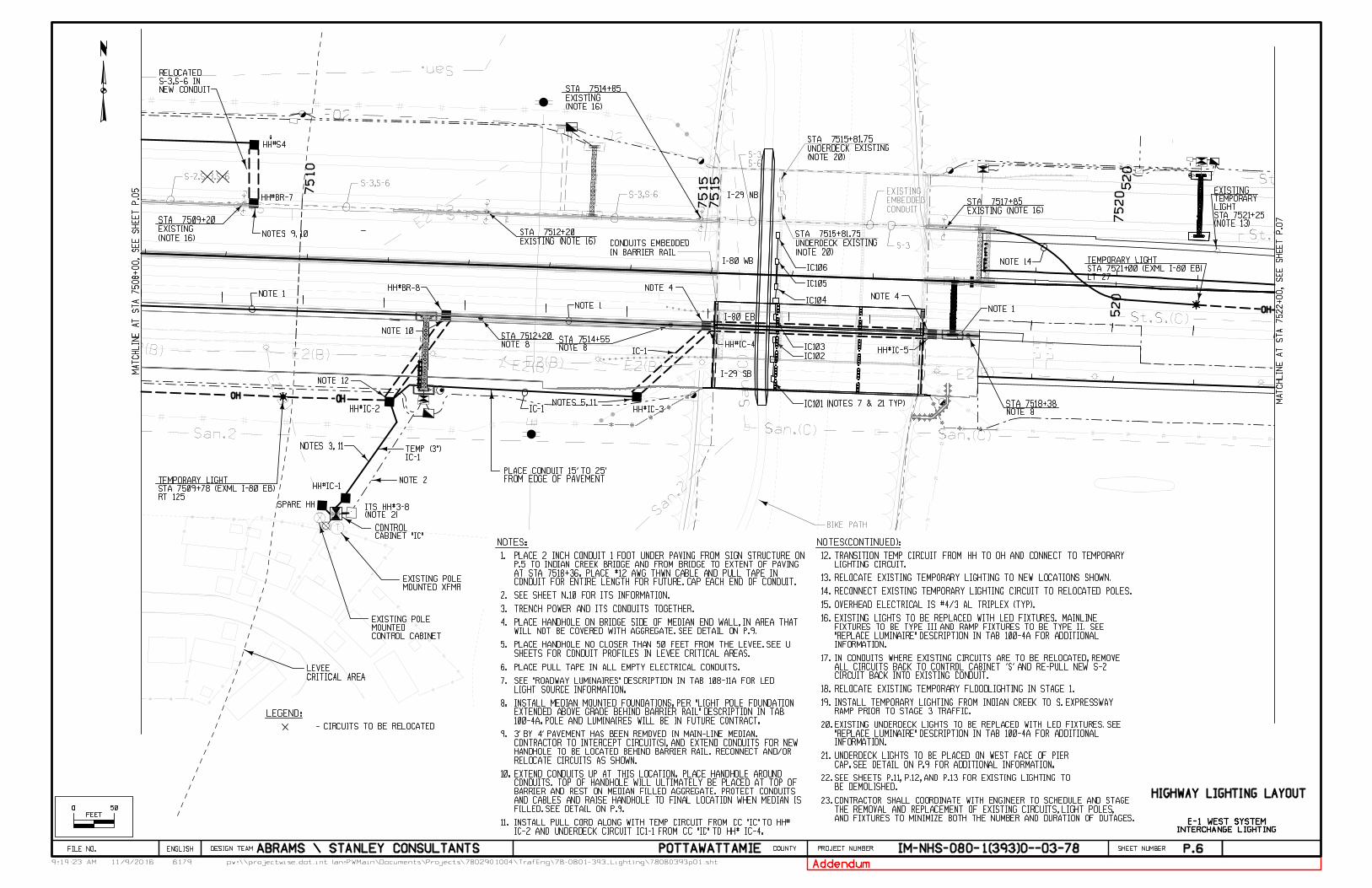
P.6
HIGHWAY LIGHTING LAYOUT
MA
TC
HLI
NE
AT
ST
A 7508
+00,
SE
E
SH
EE
T
P.05
1.
NOTES:
INTERCHANGE LIGHTING
E-1 WEST SYSTEM
2.
3.
LEGEND:
- CIRCUITS TO BE RELOCATED
4.
5.
6.
7.
8.
9.
O O 50
FEET
TRENCH POWER AND ITS CONDUITS TOGETHER.
WILL NOT BE COVERED WITH AGGREGATE. SEE DETAIL ON P.9.PLACE HANDHOLE ON BRIDGE SIDE OF MEDIAN END WALL, IN AREA THAT
10.
MA
TC
HLI
NE
AT
ST
A 7522
+00,
SE
E
SH
EE
T
P.07
PLACE PULL TAPE IN ALL EMPTY ELECTRICAL CONDUITS.
RELOCATE CIRCUITS AS SHOWN.HANDHOLE TO BE LOCATED BEHIND BARRIER RAIL. RECONNECT AND/OR CONTRACTOR TO INTERCEPT CIRCUIT(S), AND EXTEND CONDUITS FOR NEW 3' BY 4' PAVEMENT HAS BEEN REMOVED IN MAIN-LINE MEDIAN.
100-4A. POLE AND LUMINAIRES WILL BE IN FUTURE CONTRACT.EXTENDED ABOVE GRADE BEHIND BARRIER RAIL" DESCRIPTION IN TAB INSTALL MEDIAN MOUNTED FOUNDATIONS, PER "LIGHT POLE FOUNDATION
NOTES(CONTINUED):
11.
12.
13.
14.
15.OVERHEAD ELECTRICAL IS #4/3 AL TRIPLEX (TYP).
RECONNECT EXISTING TEMPORARY LIGHTING CIRCUIT TO RELOCATED POLES.
RELOCATE EXISTING TEMPORARY LIGHTING TO NEW LOCATIONS SHOWN.
FILLED. SEE DETAIL ON P.9.AND CABLES AND RAISE HANDHOLE TO FINAL LOCATION WHEN MEDIAN IS BARRIER AND REST ON MEDIAN FILLED AGGREGATE. PROTECT CONDUITS CONDUITS. TOP OF HANDHOLE WILL ULTIMATELY BE PLACED AT TOP OF EXTEND CONDUITS UP AT THIS LOCATION. PLACE HANDHOLE AROUND
16.
17.
CIRCUIT BACK INTO EXISTING CONDUIT.ALL CIRCUITS BACK TO CONTROL CABINET 'S' AND RE-PULL NEW S-2 IN CONDUITS WHERE EXISTING CIRCUITS ARE TO BE RELOCATED, REMOVE
18.
19.RAMP PRIOR TO STAGE 3 TRAFFIC.INSTALL TEMPORARY LIGHTING FROM INDIAN CREEK TO S. EXPRESSWAY
RELOCATE EXISTING TEMPORARY FLOODLIGHTING IN STAGE 1.
SEE SHEET N.10 FOR ITS INFORMATION.
LIGHT SOURCE INFORMATION.SEE "ROADWAY LUMINAIRES" DESCRIPTION IN TAB 108-11A FOR LED
IC-2 AND UNDERDECK CIRCUIT IC1-1 FROM CC "IC" TO HH# IC-4.INSTALL PULL CORD ALONG WITH TEMP CIRCUIT FROM CC "IC" TO HH#
20.
LIGHTING CIRCUIT.TRANSITION TEMP CIRCUIT FROM HH TO OH AND CONNECT TO TEMPORARY
21.
22.BE DEMOLISHED.SEE SHEETS P.11, P.12, AND P.13 FOR EXISTING LIGHTING TO
CONDUIT FOR ENTIRE LENGTH FOR FUTURE. CAP EACH END OF CONDUIT.AT STA 7518+36. PLACE #12 AWG THWN CABLE AND PULL TAPE IN P.5 TO INDIAN CREEK BRIDGE AND FROM BRIDGE TO EXTENT OF PAVING PLACE 2 INCH CONDUIT 1 FOOT UNDER PAVING FROM SIGN STRUCTURE ON
SHEETS FOR CONDUIT PROFILES IN LEVEE CRITICAL AREAS.PLACE HANDHOLE NO CLOSER THAN 50 FEET FROM THE LEVEE. SEE U
Addendum
INFORMATION."REPLACE LUMINAIRE" DESCRIPTION IN TAB 100-4A FOR ADDITIONAL FIXTURES TO BE TYPE III AND RAMP FIXTURES TO BE TYPE II. SEE EXISTING LIGHTS TO BE REPLACED WITH LED FIXTURES. MAINLINE
INFORMATION."REPLACE LUMINAIRE" DESCRIPTION IN TAB 100-4A FOR ADDITIONAL EXISTING UNDERDECK LIGHTS TO BE REPLACED WITH LED FIXTURES. SEE
CAP. SEE DETAIL ON P.9 FOR ADDITIONAL INFORMATION.UNDERDECK LIGHTS TO BE PLACED ON WEST FACE OF PIER
AND FIXTURES TO MINIMIZE BOTH THE NUMBER AND DURATION OF OUTAGES.THE REMOVAL AND REPLACEMENT OF EXISTING CIRCUITS, LIGHT POLES, CONTRACTOR SHALL COORDINATE WITH ENGINEER TO SCHEDULE AND STAGE 23.
61799:19:23 AM pw:\\projectwise.dot.int.lan:PWMain\Documents\Projects\7802901004\TrafEng\78-0801-393_Lighting\78080393p01.sht
DESIGN TEAM PROJECT NUMBER SHEET NUMBER COUNTY
11/9/2016
ENGLISHFILE NO. ABRAMS \ STANLEY CONSULTANTS POTTAWATTAMIE IM-NHS-080-1(393)0--03-78
S-3
S-3,S-6S-2,S-3,S-6
CONDUIT
EMBEDDED
EXISTING
S-6
S-3,
S-3,S-6
T
NOTE 1NOTE 1
NEW CONDUITS-3,S-6 IN RELOCATED
CABINET "IC"CONTROL
MOUNTED XFMREXISTING POLE
CONTROL CABINETMOUNTEDEXISTING POLE
CRITICAL AREA
LEVEE
NOTE 1NOTE 4
BIKE PATH
FROM EDGE OF PAVEMENTPLACE CONDUIT 15' TO 25'
(NOTE 2)ITS HH#3-8
NOTE 2
OH OH
OH
LT 27STA 7521+00 (EXML I-80 EB)TEMPORARY LIGHT
HH#BR-7
HH#BR-8
HH#IC-2
HH#IC-1
SPARE HH
HH#IC-3
HH#IC-4
HH#S4
NOTES 9, 10
NOTE 10
NOTE 8STA 7512+20
NOTE 8STA 7514+55
NOTES 3, 11
NOTE 12
NOTE 14
(NOTE 16)
EXISTING
STA 7509+20
EXISTING (NOTE 16)
STA 7512+20
EXISTING (NOTE 16)
STA 7517+85
NOTES 5, 11
NOTE 4
HH#IC-5
I-29 NB
I-80 WB
I-80 EB
I-29 SB
IC101 (NOTES 7 & 21 TYP)
NOTE 8STA 7518+38
RT 125STA 7509+78 (EXML I-80 EB)TEMPORARY LIGHT
IC102
IC103
IC104
IC105
IC106
(NOTE 16)
EXISTING
STA 7514+85
(NOTE 20)
UNDERDECK EXISTING
STA 7515+81.75
(NOTE 20)
UNDERDECK EXISTING
STA 7515+81.75
IN BARRIER RAIL
CONDUITS EMBEDDED
(NOTE 13)STA 7521+25LIGHTTEMPORARY EXISTING
IC-1
IC-1TEMP (3")
IC-1
7515
520
520
7510
7515
7520