ip-02 2:1 ratio transfer pump operating manualempirefoam.com/pdfs/pumps/transfer/manuals/ip02 inst...
TRANSCRIPT

IP-02
2:1 RATIO TRANSFER PUMP
OPERATING MANUAL
IPM, INC. Manufactured by International Pump Manufacturing, Inc.
Covers models: IP02, IP02S, IP02SST and IP02S-SST Manual Number: MIP11192008

2
IP-02, IP-02S IP02-SST, IP02S-SST
2:1 RATIO TRANSFER PUMP
OPERATION MANUAL with
PARTS IDENTIFICATION
This manual contains IMPORTANT WARNINGS and INSTRUCTIONS. Read and retain for reference.
International Pump Mfg, INC.
3107 142nd Avenue E Suite 106
Sumner, WA 98390 U.S.A.
TEL: (253) 863 2222 FAX: (253) 863 2223
Website : www.ipmpumps.com
For Technical Service Call Your Local Distributor
Copyright 2004 International Pump Mfg, Inc.
Printed: November 2008
WARNING: The equipment described herein must only be operated or serviced by properly
trained individuals, thoroughly familiar with the operating instructions and limitations of the
equipment.
Notice: All statements, information and data given herein are believed to be accurate and reliable but are presented without guarantee, warranty or responsibility of any kind expressed or implied. Statements or suggestions concerning possible use of IPM equipment are made without representation or warranty that any such use is free of patent infringement, and are not recommendations to infringe any patent. The user should not assume that all safety measures are indicated or that other measures may not be required.

3
CONTENTS:
1.0 SAFETY WARNINGS………………………………….. 4
2.0 INSTALLATION………………………………………… 7 2.1 MOUNTING CONFIGURATION………………………… 8
3.0 OPERATIONS………………………………………….. 9
4.0 MAINTENANCE AND REPAIR SECTIONS 4.1 AIR MOTOR DISASSEMBLY…………………………… 11 4.2 AIR MOTOR ASSEMBLY……………………………….. 13 4.3 DISASSEMBLY LOWER FLUID SECTION…………. 14 4.4 ASSEMBLY LOWER FLUID SECTION…………….. 16
5.0 PARTS IDENTIFICATION 5.1 PARTS DIAGRAM FOR AIR MOTORS (IP02/IP02S).. 17 5.2 PARTS LIST FOR AIR MOTORS (IP02/IP02S)……… 18 5.3 FLUID SECTION PARTS DIAGRAM IP02…………… 19 5.4 PARTS LIST IP-02…………………………………………. 20 5.5 FLUID SECTION PARTS DIAGRAM IP-02SST……….. 21 5.6 PARTS LIST IP-02SST……………………………………. 22 5.7 FLUID SECTION PARTS DIAGRAM IP02-S..….……. 23 5.8 PARTS LIST IP02S………………………………….. 24 5.9 FLUID SECTION PARTS DIAGRAM IP02S-SST…….. 25 5.10 PARTS LIST IP02-SST………………………………….. 26
6.0 REPAIR KITS………………………………………………… 27
7.0 TROUBLESHOOTING…………………………………. 28
8.0 TECHNICAL SPECIFICATIONS………………………. 29
9.0 WARRANTY AND DISCLAIMER………………………. 32
4
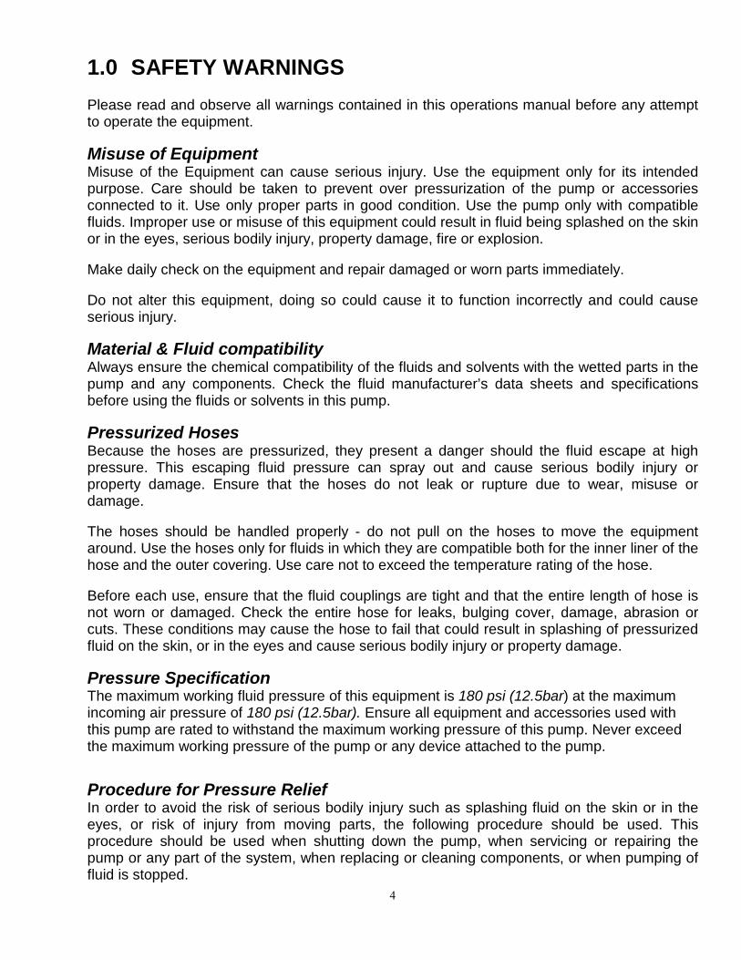
1.0 SAFETY WARNINGS Please read and observe all warnings contained in this operations manual before any attempt to operate the equipment. Misuse of Equipment Misuse of the Equipment can cause serious injury. Use the equipment only for its intended purpose. Care should be taken to prevent over pressurization of the pump or accessories connected to it. Use only proper parts in good condition. Use the pump only with compatible fluids. Improper use or misuse of this equipment could result in fluid being splashed on the skin or in the eyes, serious bodily injury, property damage, fire or explosion. Make daily check on the equipment and repair damaged or worn parts immediately. Do not alter this equipment, doing so could cause it to function incorrectly and could cause serious injury. Material & Fluid compatibility Always ensure the chemical compatibility of the fluids and solvents with the wetted parts in the pump and any components. Check the fluid manufacturer’s data sheets and specifications before using the fluids or solvents in this pump. Pressurized Hoses Because the hoses are pressurized, they present a danger should the fluid escape at high pressure. This escaping fluid pressure can spray out and cause serious bodily injury or property damage. Ensure that the hoses do not leak or rupture due to wear, misuse or damage. The hoses should be handled properly - do not pull on the hoses to move the equipment around. Use the hoses only for fluids in which they are compatible both for the inner liner of the hose and the outer covering. Use care not to exceed the temperature rating of the hose. Before each use, ensure that the fluid couplings are tight and that the entire length of hose is not worn or damaged. Check the entire hose for leaks, bulging cover, damage, abrasion or cuts. These conditions may cause the hose to fail that could result in splashing of pressurized fluid on the skin, or in the eyes and cause serious bodily injury or property damage. Pressure Specification The maximum working fluid pressure of this equipment is 180 psi (12.5bar) at the maximum incoming air pressure of 180 psi (12.5bar). Ensure all equipment and accessories used with this pump are rated to withstand the maximum working pressure of this pump. Never exceed the maximum working pressure of the pump or any device attached to the pump.
Procedure for Pressure Relief In order to avoid the risk of serious bodily injury such as splashing fluid on the skin or in the eyes, or risk of injury from moving parts, the following procedure should be used. This procedure should be used when shutting down the pump, when servicing or repairing the pump or any part of the system, when replacing or cleaning components, or when pumping of fluid is stopped.

5
1. Close the air valve to the pump. 2. Use the air bleed down valve (see installation instructions) to relieve the air pressure in
the system. 3. Relieve the fluid pressure by holding a grounded metal pail in contact with the metal
part of the fluid dispense valve and slowly opening the valve. 4. With a container ready to catch the fluid open the drain valve (see installation
instructions). 5. It is a good practice to leave the drain valve open until it is time to dispense fluid again. If you are unsure that the fluid pressure has been relieved (due to a blockage in a component or a hose) be careful to relieve the pressure by slowly loosening the hose end coupling to allow the fluid pressure to escape slowly. After the pressure has been relieved, the fitting can be removed completely and any blockages removed. Hazards from Fire or Explosion Hazards exist when sparks can ignite vapors or fumes from flammable or combustible materials or other hazardous conditions (explosive dusts, etc.). These sparks can be created from plugging in or unplugging an electrical supply cord. Sparks can also be created from the static electricity generated by the flow of fluid through the pump and hose. Every part of the equipment must be properly grounded to prevent static electricity from generating a spark and causing the pump or system to become hazardous. These sparks can cause a fire, explosion, and serious bodily injury and property damage. Ensure that the pump and all components and accessories are properly grounded and that electrical supply cords are not plugged in or unplugged when these hazards exist. Should any evidence of static electricity (sparks or small shocks while in contact with the equipment) exists, discontinue the operation immediately. Investigate the source of the static electricity and correct the grounding problem. Do not use the system until the grounding problem is repaired. Grounding Procedures Grounding of the pump and all other dispensing equipment is necessary to minimize the possibility of sparks due to static electricity. Grounding must be in compliance with local electrical codes. Check with the local authorities for requirements in your area and with the type of equipment being used. Ensure that all the following equipment is grounded: 1. Air Compressor: Follow the grounding procedures as recommended
by the manufacturer. 2. Air Hoses: Use grounded air hoses. 3. Fluid Container used to
supply the system: Grounding must be done according to local codes. 4. Pump: Follow the procedures included referring to Figure 1. 5. Fluid Hoses: Use grounded fluid hoses. 6. Dispensing Valve: The valve must be metal to conduct through the fluid hose to the pump which must be properly grounded.

6
7. Dispensing Point: Grounding must be done according to local codes. 8. Solvent Containers: Grounding must be done according to local codes. Use
metal conductive pails that are properly grounded. 9. Grounding while Maintain conductivity by firmly holding the metal part of the
dispensing, cleaning, dispensing valve to the side of a grounded metal container. or relieving:
FIGURE 1 Grounding the Pump: Follow these procedures for grounding the pump. Loosen the lock screw (W) to allow insertion of one end of a 12 ga. (1.5 mm2) minimum size wire into the hole in the side of the lug (Z). Insert the wire (Y) and tighten the lock screw securely. The other end of the ground wire must be secured to a true earth ground.
Hose Grounding: It is very important that the hoses used for both air and the fluid be a grounding type and that this ground continuity is maintained. Regular checks of the hose ground resistance (with a resistance meter using a suitable range) and a comparison to the Manufacturer’s Specification will ensure the ground is within specifications. If it is not within specified limits it should be replaced immediately. Solvent Cleaning: While cleaning the system with solvent, hold the metal part of the dispensing valve in contact with a grounded metal pail to minimize the possibility of splashing fluid on the skin or in the eyes or static sparks. Use low fluid pressure for additional safety.
Hazards From Moving Parts: Use the Pressure Relief Procedure (page 9) to prevent the pump from starting unintentionally when not desired. Please observe that moving parts present a pinching hazard to fingers or other body parts. Always stay clear of moving parts when starting or operating the pump. Safety Standards: Safety standards have been established by the United States Government under the Occupational Safety and Health Act. These standards should be consulted as they apply to the hazards and type of equipment being used.

7
2.0 INSTALLATION
FIGURE 2 Figure 2 depicts a typical installation provided as a guide for your reference. Select and install optional accessories required. Feel free to call an IPM representative or the IPM Technical Department for assistance.

8
2.1 Mounting Configuration Install the necessary accessories in sequence using Figure 2 as a guide. An Air Control Valve (K) for Controlling air flow is required with the equipment. To minimize the risk of serious bodily injury such as splashing fluid on the skin or in the eyes; or risk of injury from moving parts, install the following accessories in your system. 1. Bleed-off master air valve (D)
This valve will relieve the air trapped within the system after the pump is stopped. Air that is trapped between this valve and the pump can cause the pump to reciprocate unintentionally, which may cause harm to the operator.
2. Fluid Drain Valve (G) The fluid drain valve (use a metal valve for grounding purposes) is installed to relieve fluid pressure in the pump, hose or the dispensing valve when the pump is stopped. The relief of pressure by the dispensing valve, which at times is inadequate if there is a clog or restriction in the hose or the dispensing valve, can be achieved by using the fluid drain valve (G).
3. Low level cut-off valve or runaway safety valve The low level cut-off valve should be installed at the fluid intake port of the pump. It shuts off the fluid intake when the fluid level is too low, causing the pump to stall. This is to prevent the pump from running empty. If not, then a runaway safety valve should be installed. This valve shuts off the air supply to the pump if the pump accelerates beyond the pre-set value when the fluid level is too low and the pump is pumping air, or there is insufficient fluid for normal pump operation.
Connect an air lubricator (C). The lubricator provides proper lubrication to the air motor. (see daily maintenance check). Next, install a bleed-off master air valve (D). This valve is required in your system to relieve trapped air (as explained above). Air Filter (E) helps to remove dirt and foreign particles from the supply air, water moisture also will be trapped within this filter. Be sure to release the trapped water daily as a good housekeeping practice (Also see daily maintenance check). Connect a grounded air supply hose for the supply of air. For the fluid section, connect one fluid drain valve (G) directly after the outlet of the pump. Be sure to connect it pointing downwards for safety. Connect a grounded fluid hose (M) to the fluid outlet 3/4” NPTF. Grounding of the pump and accessories are to be ensured before operation. Observe all OSHA regulations and other safety regulations.

9
3.0 OPERATION
Start up and Adjustment of the Pump (Refer figure 2, page 7) Ensure that installation is fully completed before proceeding to start up operations. 1. Ensure that the air control valve (K) is closed. Open the bleed-type master air valves
(D). Connect the quick disconnect coupler to the male fitting. 2. Into a grounded metal container, open the dispensing valve (G) slowly. Ensure metal-to-
metal contact between the container and the valve. 3. Adjust the pump air control valve (K) slowly for pressure just enough to start running the
pump. This is to prime all air within the system. After all the air has been expelled from the lines, close the dispensing valve. During the priming of the pump, the pump runs when the dispensing valve is opened and stop when the valve is closed.
4. Turn the air regulator slowly until sufficient flow from the dispensing valve is achieved.
Remember to run the pump always at the lowest possible speed necessary to achieve what is desired. Never exceed the maximum working pressure of any component in the system.
5. The pump should not be left to run dry of the fluid being pumped. When running empty,
the pump speed will become very fast and probably cause damage. During operation, should the pump be found to run too fast, stop it immediately and check the fluid supply. Is the fluid level in the drum too low or empty? If air has gone into the system, do a priming procedure. Ensure that all air has been expelled from the lines before beginning operations again. Flush the pump or leave it filled with a compatible solvent when not in use.
6. Always follow the Pressure Relief Procedure should the pump be put away for any
period of time or during system shut off at the end of the day.
Daily Maintenance Check 1. Ensure sufficient lubricant in the air lubricator. 2. Drain the moisture trapped in the air pressure regulator. Clean and flush the pump thoroughly with care and appropriate cleaning fluid to obtain maximum service life of the equipment.
Procedure For Pressure Relief In order to avoid the risk of serious bodily injury such as spraying fluid on the skin or in the eyes, or risk of injury from the moving part, the following procedure should be used. This procedure should be used when shutting down the pump, servicing or repairing the pump or any part of the system, replacing or cleaning components, or if the pumping of fluid has stopped.
1. Close the air valve (D) of the pump. 2. Use the air bleed down valve (see installation instructions) to relieve the air
pressure in the system.

10
Warning To reduce the risk of static sparking, splashing fluid in the eyes or on the skin, follow the Pressure Relief Procedure before flushing.
For your safety, read the Fire or Explosion Hazard before flushing and follow all the recommendations furnished.
3. Relieve the fluid pressure by holding a grounded metal pail in contact with metal
part of the fluid dispense valve (G) and slowly opening the valve.
4. With a container ready to catch the fluid open the drain valve (G) (see installation
instructions).
5. It is a good practice to leave the drain valve (G) open until it is time to dispense
fluid again. If you are unsure that the fluid pressure has been relieved due to a blockage in a component or a hose, relieve pressure by slowly
Flush the Pump before Using It
loosening the hose end coupling to allow the fluid pressure to escape. After the pressure has been relieved, the fitting can be removed completely and any blockages removed.
1. The pump is tested with lightweight DOP oil, which is left in to protect the pump parts. If
the fluid you are pumping may contaminated by oil, Flush out the oil with a compatible solvent before using the pump. Follow the Flushing Instruction below:
2. If you are pumping fluid that dries, hardens or sets up, flush the system with a compatible solvent as often as necessary to prevent build-up of dried fluid in the pump or hoses.
3. If the pump is being used to supply a circulating system, allow the solvent to circulate
through the entire system for at least 30 minutes every 48 hours- more often if necessary to prevent any undesired settling.
4. Always fill the wet-cup 1/2 full of Throat Seal Liquid (TSL) or a compatible solvent to
keep the fluid from drying on the displacement rod and/or damaging the pump throat packing.
5. Lubricate the throat packing frequently when you are pumping a non-lubricating fluid, or
are shutting down for more than a few days. Shut down & care of the Pump For overnight shut down, follow the Pressure Relief Procedure on page 9. Always stop the pump at bottom of the stroke to prevent the fluid from drying on the exposed displacement rod, which could damage the throat packing.

11
4.0 IP-02 Maintenance & Repair Section
4.1 Air Motor Disassembly Procedure
1. Follow the Procedure For Pressure Relief on page 9. It is very important to relieve all air and fluid line pressure, as well as pump pressure before proceeding to the next step or injury can occur.
2. Remove inlet and outlet hoses. Place the pump in a vise or other holding device.
If you know that you just need to work on the air motor, the pump can simply be left in the drum it is operating in.
3. Clamp on the housing with the outlet hole against one of the jaws of the vice.
When clamping the housing- either the air motor assembly or the lower tube and/or foot valve can be removed.
Use a strap wrench to remove the air motor assembly. The pump assembly can be removed from the air motor by disengaging the Piston Rod.

12
Remove the air cylinder either by hand or by using a strap wrench.
Air piston assembly with the Air Cylinder removed.
Place a pair of channel-lock pliers on the knurled area and a crescent wrench on the flats to remove the air piston assembly. Examine the spring in the air motor cap to ensure that it is not damaged or loose. Examine the gasket in the air motor cap, and replace as needed. This gasket seals the cylinder cap to the air cylinder. Also inspect the lower return spring to ensure it is secured correctly into the air motor base assembly.
13
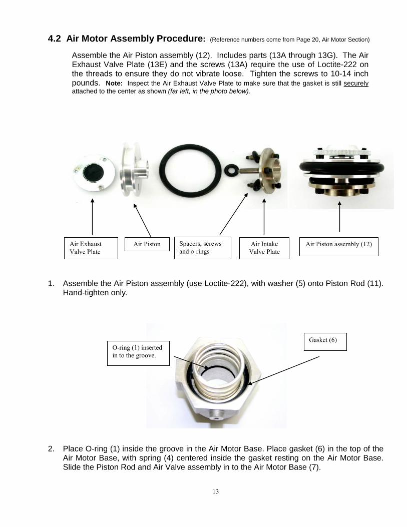
4.2 Air Motor Assembly Procedure: (Reference numbers come from Page 20, Air Motor Section)
Assemble the Air Piston assembly (12). Includes parts (13A through 13G). The Air Exhaust Valve Plate (13E) and the screws (13A) require the use of Loctite-222 on the threads to ensure they do not vibrate loose. Tighten the screws to 10-14 inch pounds. Note: Inspect the Air Exhaust Valve Plate to make sure that the gasket is still securely
attached to the center as shown (far left, in the photo below).
1. Assemble the Air Piston assembly (use Loctite-222), with washer (5) onto Piston Rod (11).
Hand-tighten only. 2. Place O-ring (1) inside the groove in the Air Motor Base. Place gasket (6) in the top of the
Air Motor Base, with spring (4) centered inside the gasket resting on the Air Motor Base. Slide the Piston Rod and Air Valve assembly in to the Air Motor Base (7).
Air Piston assembly (12) Air Intake Valve Plate
Spacers, screws and o-rings
Air Piston Air Exhaust Valve Plate
O-ring (1) inserted in to the groove.
Gasket (6)

14
3. Place the conical spring (2) into the groove in the Air Cylinder Cap (10) followed by Gasket
(6). Clamp the Air Motor Base in to a vice and use a strap wrench to assemble the Air Cylinder (3) and the Air Cylinder Cap to the Air Motor Base. Hand-tighten the Air Cylinder cap.
4. Place the Connecting Ring (9) around the Connecting Rod Housing (8) and hand-tighten.
4.3 Disassembly Lower Fluid Section
1. Remove the foot valve while holding the cylinder with a strap wrench.
2. With the upper air motor assembly already removed, you should be able to simply push from the upper ball end, the complete assembly out the bottom of the lower section.
3. Use two wrenches and dismantle the upper pump section. Note the orientation of the Teflon cups. One goes up, followed by a wear ring in the center, and one goes down followed by a lower support washer. Use Loctite-222 when re-installing.
Upper portion of the Lower Connecting Rod assembly.
Spring must be pushed under the lip inside the cap

15
Internal foot valve of an IP-02 pump.
Internal foot valve disassembled. Clean, inspect or replace (if necessary) these components before re-assembly. Use Loctite-222 when re-installing. After the lower piston rod is inspected and proper parts replaced/cleaned as needed, inspect the lower body assembly
and make sure that they are also clean and free from any rough scratches. Grease and push this assembly back up from the bottom into the pump’s cylinder. Just push it in far enough to re attach the foot valve.
IP-02 lower foot valve parts. On the stubby version there are ¾” female pipe threads under the Foot Valve- on the drum length IP02 there are not. Should you need to extend in to your container farther, it is recommended to install a proper Cylinder Extension Tube to keep the foot valve at the lowest possible point.
Be sure to clean and inspect and replace any of the above items if needed.
You will need to re-assemble the foot valve assembly the same way that you removed it.

16
4.4 Attaching lower fluid assembly to the Air Motor assembly
The Piston Rod is actually inside the Air Motor assembly- which has been removed so you can see more detail. Notice how the Upper Connecting Rod is being inserted at an angle. This is to ensure that the ball on the end correctly engages the slot or notch in the photo on the left. You will need to “hook” the ball in to the slot by moving at an angle- and then press it towards the center of the notch. Note: the lower section will need to have the Piston Rod extended, and the Air Motor will need to be in the down position in order for you to have enough length to hook these two components together. Connect the assembly to the lower section as shown. You should now be ready to re-install the pump into your container. Attach the fluid hose first and tighten before attaching the air line and turning the air supply back on.

17
5.0 PARTS IDENTIFICATION:
5.1 Parts Drawing for AIR MOTOR IP-02 (Drum Length) Parts Drawing for AIR MOTOR IP02S (Stubby)
14A: Complete air motor assy. for IP02. 14B: Complete air motor assy. for IP02S

18
5.2 Parts List for AIR MOTOR IP-02 (Drum Length) Parts List for AIR MOTOR IP02S (Stubby)
Ref No.
New Part Number
Old Part Number Description QTY
1* 500206 02-156-698 O-ring 1 2 500284 02-157-630 SPRING, conical 1
3 500203 02-157-632 Air cylinder (IP02) 1
500241 02-186-565 Air cylinder (IP02S) 1
4 500204 02-157-633 SPRING, compression 1
5 500104 02-157-872 WASHER, valve 1 6* 500236 02-158-109 GASKET, rubber 2 7 500205 02-161-770 BASE, air motor 1
8 500207 02-161-771 HOUSING, connecting rod 1
9 500212 02-161-772 RING, connecting 1
10 500200 02-204-465 Air cylinder cap 1 11 700027 02-204-723 ROD, piston 1
12 700055 02-220-168
Air valve & piston assembly. (Includes 13a-13g) 1
13a 500288 02-220-884
SCREW, SHCS (6-32X1” with copper gasket) 3
13b 500140 02-181-485 SPACER 3 13c 500137 02-189-210 PISTON, air 1 13d 500139 02-181-487 Air intake valve plate 1
13e 500138 02-162-729 Air exhaust valve plate 1
13f 500141 02-108-357 O-Ring 1 13g 500144 02-108-358 O-Ring 3
14A 700038 02-204-722 IP02 complete air motor 1
14B 700046 02-223-953 IP02S complete air motor 1
* Supplied in the air motor repair kit 601011.

19
5.3 Parts drawing for IP-02 Fluid Section for C/Steel (Drum Length)

20
5.4 Parts List for IP-02 Fluid Section for C/Steel (Drum Length)
Ref No.
New Part Number
Old Part Number Description QTY
1 700038 02-204-722 AIR MOTOR 1
2 700047 02-208-197 Displacement pump assy. (includes items 3-31) 1
3* 500213 02-102-596 O-Ring, Teflon 1 4 500268 02-101-750 BALL, piston valve 1 5 500269 02-101-917 BALL, intake valve 1
6* 500221 02-161-788 CUP PACKING, Teflon 2 7* 500222 02-186-647 BEARING, Piston 1 8* 500227 02-161-793 CUP PACKING, Teflon 2 9* 500228 02-186-648 BEARING, Piston 1 10 500107 02-104-029 LUG, grounding 1 11 500230 02-164-250CS PIN, ball stop 1 12 500210 02-166-564 BEARING 1 13 500225 02-169-293 HOUSING, Piston valve 1 14 500224 02-169-294 ROD, lower connecting 1 15 500226 02-169-295 WASHER, back-up 1 16 500223 02-169-296 WASHER, back-up 1
17 700017 02-990-017 FRAME, displacement pump 1
18 700028 02-208-198 Rod, upper connecting 1 19 500211 02-169-298 RETAINER, packing 1 20 500229 02-208-201 BODY, piston 1 21 500289 02-208-202X Foot Valve 1 22 500233 02-100-040 PLUG, pipe, 3/8" NPT 1 23 500232 02-103-147 PLUG. Pipe, 1/16" NPT 1 24 500108 02-104-582 SCREW, M5X10 1 25 500238 02-990-359-A ADAPTER,BUNG 1 26 500239 02-990-359-B CAP, bung adapter 1 27 500053 02-990-359-C GASKET 1 28 500240 02-990-359-D O-RING 1
(25-28) 700019 02-990-359 Complete Bung Assy. 1 29* 500237 02-990-032 O-RING 1 30 500220 02-990-017-5 CYLINDER 1
31* 500066 02-990-038 O-RING 1 32 810201 02-208-177 Complete IP02 Pump 1
*Supplied in the repair kit P/N 601009.

21
5.5 Parts drawing for IP-02SST Fluid Section for S/Steel (Drum Length)

22
5.6 Parts List for IP-02SST Fluid Section for S/Steel (Drum Length)
Ref No.
New Part Number
Old Part Number Description QTY
1 700038 02-204-722 AIR MOTOR 1
2 700048 02-204-724 Displacement pump assy. (includes items 3-31) 1
3* 500213 02-102-596 O-Ring, Teflon 1 4 500268 02-101-750 BALL, piston valve 1 5 500269 02-101-917 BALL, intake valve 1
6* 500221 02-161-788 CUP PACKING, Teflon 2 7* 500222 02-186-647 BEARING, Piston 1 8* 500227 02-161-793 CUP PACKING, Teflon 2 9* 500228 02-186-648 BEARING, Piston 1 10 500107 02-104-029 LUG, grounding 1 11 500264 02-164-250 PIN, ball stop 1 12 500210 02-166-564 BEARING 1 13 500261 02-161-791 HOUSING, Piston valve 1 14 500260 02-162-239 ROD, lower connecting 1 15 500262 02-161-792 WASHER, back-up 1 16 500259 02-162-238 WASHER, back-up 1
17 700023 02-990-041 FRAME, displacement pump 1
18 700030 02-204-885 Rod, upper connecting 1 19 500252 02-990-043 RETAINER, packing 1 20 500263 02-161-795 BODY, piston 1 21 500290 02-164-251X Foot Valve 1 22 500267 02-101-748 PLUG, pipe; 3/8npt 1 23 500266 02-990-045 PLUG. Pipe; 1/16npt 1 24 500108 02-104-582 SCREW, M5X10 1 25 500238 02-990-359-A ADAPTER, BUNG 1 26 500239 02-990-359-B CAP, bung adapter 1 27 500053 02-990-359-C GASKET 1 28 500240 02-990-359-D O-RING 1
(25-28) 700019 02-990-359 Complete Bung Assy. 1 29* 500237 02-990-032 O-RING 1 30 500258 02-990-041-6 CYLINDER 1
31* 500066 02-990-038 O-RING 1
32 810202 02-223-954 Complete IP02-SST Pump 1
*Supplied in the repair kit P/N 601009.

23
5.7 Parts drawing for IP-02S Fluid Section for C/Steel Stubby

24
5.8 Parts List for IP-02S Fluid Section C/Steel Stubby
Ref No.
New Part Number
Old Part Number Description QTY
1 700046 02-223-953 AIR MOTOR 1
2 700049 02-223-955CS Displacement pump assy. (includes items 3-33) 1
3 500233 02-100-040 PLUG, pipe 3/8” NPT 1 4 500268 02-101-750 BALL, piston valve 1 5 500269 02-101-917 BALL, intake valve 1
6* 500221 02-161-788 CUP PACKING, Teflon 2 7* 500222 02-186-647 BEARING, Piston 1 8* 500227 02-161-793 CUP PACKING, Teflon 2 9* 500228 02-186-648 BEARING, Piston 1 10 500107 02-104-029 LUG, grounding 1 11 500230 02-164-250CS PIN, ball stop 1 12 500210 02-166-564 BEARING 1 13 500225 02-169-293 HOUSING, Piston valve 1 14 500246 02-186-569CS ROD, lower connecting 1 15 500226 02-169-295 WASHER, back-up 1 16 500223 02-169-296 WASHER, back-up 1
17 700020 02-990-018 FRAME, displacement pump 1
18 700029 02-223-957CS Rod, upper connecting 1 19 500211 02-169-298 RETAINER, packing 1 20 500229 02-208-201 BODY, piston 1 21 500291 02-166-609CSX Foot Valve 1 22 500232 02-103-147 PLUG. Pipe; 1/16” NPT 1
23* 500248 02-166-612 O-RING, Teflon 1 24 500249 02-188-037CS ADAPTER, intake 1
25* 500213 02-102-596 O-RING, Teflon 1 26 500238 02-990-359-A ADAPTER,BUNG 1 27 500239 02-990-359-B CAP, bung adapter 1 28 500053 02-990-359-C GASKET 1 29 500240 02-990-359-D O-RING 1
(26-29) 700019 02-990-359 Complete Bung Assy. 1 30 500108 02-104-582 SCREW, M5X10 1
31* 500066 02-990-038 O-RING 1 32 500245 02-990-018-5 CYLINDER 1
33* 500237 02-990-032 O-RING 1 34 810203 02-223-954CS Complete IP02S Pump 1
*Supplied in the repair kit P/N 601013.

25
5.9 Parts drawing for IP-02S-SST Fluid Section S/Steel Stubby

26
5.10 Parts list for IP-02S-SST Fluid Section S/Steel Stubby Ref No.
New Part Number
Old Part Number Description QTY
1 700046 02-223-953 AIR MOTOR 1
2 700050 02-223-955 Displacement pump assy. (includes items 3-33) 1
3 500267 02-101-748 PLUG, pipe 3/8" NPT 1 4 500268 02-101-750 BALL, piston valve 1 5 500269 02-101-917 BALL, intake valve 1
6* 500221 02-161-788 CUP PACKING, Teflon 2 7* 500222 02-186-647 BEARING, Piston 1 8* 500227 02-161-793 CUP PACKING, Teflon 2 9* 500228 02-186-648 BEARING, Piston 1 10 500107 02-104-029 LUG, grounding 1 11 500264 02-164-250 PIN, ball stop 1 12 500210 02-166-564 BEARING 1 13 500261 02-161-791 HOUSING, Piston valve 1 14 500275 02-186-569 ROD, lower connecting 1 15 500262 02-161-792 WASHER, back-up 1 16 500259 02-162-238 WASHER, back-up 1
17 700025 02-990-042 FRAME, displacement pump 1
18 700031 02-223-957 Rod, upper connecting 1 19 500252 02-990-043 RETAINER, packing 1 20 500263 02-161-795 BODY, piston 1 21 500292 02-166-609X Foot Valve 1 22 500266 02-990-045 PLUG. Pipe; 1/16" NPT 1
23* 500248 02-166-612 O-RING, Teflon 1 24 500274 02-188-037 AFAPTER, intake 1
25* 500213 02-102-596 O-RING, Teflon 1 26 500238 02-990-359-A ADAPTER, BUNG 1 27 500239 02-990-359-B CAP, bung adapter 1 28 500053 02-990-359-C GASKET 1 29 500240 02-990-359-D O-RING 1
(26-29) 700019 02-990-359 Complete Bung Assy. 1 30 500108 02-104-582 SCREW, M5X10 1
31* 500066 02-990-038 O-RING 1 32 500272 02-990-042-3 CYLINDER 1
33* 500237 02-990-032 O-RING 1 34 810204 02-223-954 Complete IP02S-SST 1
*Supplied in the repair kit P/N 601013.

27
6.0 Repair Kits IP02 Air Motor
New Part Number Old Part Number Description Qty 601011 02-990-053 Air Motor Repair Kit N/A 500236 02-158-109 O-Ring 2 500206 02-156-698 O-Ring 1
IP02 Fluid Section
New Part Number Old Part Number Description Qty 601009 02-990-051 Fluid Section Repair Kit N/A 500213 02-102-596 O-Ring 1 500221 02-161-788 Packing 2 500222 02-186-647 Bearing 1 500227 02-161-793 Packing 2 500228 02-186-648 Bearing 1 500237 02-990-032 O-Ring 1 500066 02-990-038 O-Ring 1
IP02S Fluid Section
New Part Number Old Part Number Description Qty 601013 02-990-052 Fluid Section Repair Kit N/A 500213 02-102-596 O-Ring 1 500221 02-161-788 Packing 2 500222 02-186-647 Bearing 1 500227 02-161-793 Packing 2 500228 02-186-648 Bearing 1 500237 02-990-032 O-Ring 1 500066 02-990-038 O-Ring 1 500248 02-166-612 O-Ring 1
28
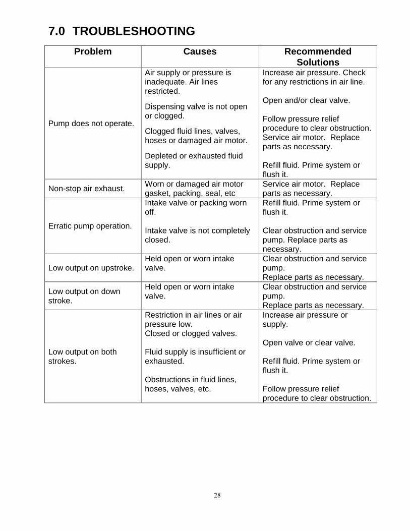
7.0 TROUBLESHOOTING
Problem Causes Recommended Solutions
Pump does not operate.
Air supply or pressure is inadequate. Air lines restricted. Dispensing valve is not open or clogged. Clogged fluid lines, valves, hoses or damaged air motor. Depleted or exhausted fluid supply.
Increase air pressure. Check for any restrictions in air line. Open and/or clear valve. Follow pressure relief procedure to clear obstruction. Service air motor. Replace parts as necessary. Refill fluid. Prime system or flush it.
Non-stop air exhaust. Worn or damaged air motor gasket, packing, seal, etc
Service air motor. Replace parts as necessary.
Erratic pump operation.
Intake valve or packing worn off. Intake valve is not completely closed.
Refill fluid. Prime system or flush it. Clear obstruction and service pump. Replace parts as necessary.
Low output on upstroke. Held open or worn intake valve.
Clear obstruction and service pump. Replace parts as necessary.
Low output on down stroke.
Held open or worn intake valve.
Clear obstruction and service pump. Replace parts as necessary.
Low output on both strokes.
Restriction in air lines or air pressure low. Closed or clogged valves. Fluid supply is insufficient or exhausted. Obstructions in fluid lines, hoses, valves, etc.
Increase air pressure or supply. Open valve or clear valve. Refill fluid. Prime system or flush it. Follow pressure relief procedure to clear obstruction.

29
8.0 TECHNICAL SPECIFICATIONS
(A) Recommended Application Chart Industry Application Viscosity
Range(CPS)
Alcohol 0-100
Dye 0-1000
Methyl Chloride 0-200 Solvents 0-500
Paint(Latex) 100-1000
Paint(Oil base) 100-800
Sealer(Wood) 100-800 Stain(Oil base) 100-1000
Anti-Freeze 30-100
Die Lubricant 30-50
Gear Oil 200-1000
Lubricant 100-1500
Mold Release Agent 30-100 Oil 100-500
(B) Technical Specifications
Fluid to Air Pressure Ratio…..……………….………………………. 2 : 1 Max. Output Flow(intermittent)(Stubby)…………………………….. 2.5gpm (9.5 l/pm) Max. Output Flow(intermittent)(Drum)……………………………..... 3.75gpm (11.7 l/pm) Max. Output Flow(continuous)(Stubby)…………………………….. 2.0pm (7.6 l/pm) Max. Output Flow(continuous)(Drum)……………………………..... 2.5gpm (9.5 l/pm) Maximum Output Fluid Pressure…………...…………..……………. 360 psi (24.8bar) Air Input Pressure Range…………………………………………….. 30 – 180 psi (2 – 12.4 bar) Air Inlet Size…………………………………………………………..... 1/4” NPT(f) Fluid Inlet Size…………………………………………………………. 3/4” NPT(m) Fluid Outlet Size ………………………………………………………. 3/4” NPT(f) Weight Drum Length……………………………………………….. Stubby…………………………………………….….
16 lbs (7.3 kg) 14 lbs (6.4 Kg)
Packing.………………………………………………………………… Teflon, UHMWPE Rod and Cylinder………………………………………………………. SST 304

30

31

32
9.0 WARRANTY AND DISCLAIMER
International Pump Manufacturing, Inc. (IPM) warrants the equipment it manufactures to be free of defects in material and workmanship for a period of one year from the day of sale by an authorized IPM distributor to the original purchaser. IPM will at its discretion repair or replace any part of the equipment proven to be defective. This warranty applies only when the equipment is used for the intended purpose and has been installed, operated and maintained in accordance with the written recommendations. A condition of the warranty is the prepaid return of the equipment to an authorized distributor of IPM who shall provide verification of the warranty claim. IPM will repair or replace, free of charge any parts found and verified to be defective. Transportation will be prepaid for the repaired or replaced parts under warranty. Should the inspection of the equipment not reveal any defect in material or workmanship, repairs will be made at standard charges, which include parts, labor and transportation. The warranty does not apply or nor will IPM be liable for damage, wear, or malfunction of equipment caused by improper installation, misuse, abrasion, corrosion, negligence, accident, tampering, lack of improper maintenance, or by substitution of non-IPM parts. Additionally IPM shall not be liable for and the warranty does not apply to wear, damage, or malfunction caused by incompatibility of accessories, components, structures, equipment or materials not supplied by IPM. The warranty does not apply to nor will IPM be responsible for the improper operation, maintenance, design, manufacture, installation of components, accessories, equipment or structures not supplied by IPM. The warranty is void unless the Warranty Registration Card is properly completed and returned to International Pump, Inc. within ONE month of date of sale. LIMITATIONS AND DISCLAIMERS This warranty is the sole and exclusive remedy for the purchaser. No other warranties (expressed or implied), including warranties for fitness of purpose or merchantability, or non-contractual liabilities are made, including product liability, whether on negligence or strict liability basis. Liability for directly special or non-contractual damages or loss is expressly excluded and denied. IPM’s liability shall in no case exceed the amount of the purchase price. IPM does not warrant and disclaims implied warranties of merchantability and fitness for a particular purpose, components, accessories, equipment, materials sold but not manufactured by IPM. These items (switches, hoses, etc.) are subject to the provisions of the warranty of the manufacturer of these items. IPM will provide reasonable assistance with warranty claims on these items.

3107 142nd Avenue East, Suite 106 Sumner, Washington
Telephone: (253)863-2222 Fax: (253)863-2223 Website:
ipmpumps.com
Revised 12/16/08