ip-237 - nyab · rail vehicle systems ip-237 rev. 06 (2/16/15) -en operator’s manual ep-60 /...
TRANSCRIPT

. . . . . . . . . . . . . . . . . . . .
. . . . . . . . . . . . . . . . . . . .
. . . . . . . . . . . . . . . . . . . .
. . . . . . . . . . . . . . . . . . . .
R a i l V e h i c l e S y s t e m s
I P - 2 3 7Rev. 06 (2/16/15) -en
Operator’s ManualEP-60 / CCBII with Locomotive Display Interface (IFC, CCA, FIRE)

EP-60 / CCBII with Locomotive Display InterfaceOperator’s Manual
Doc. No. IP-237Revision: 06 2/16/15-en
This document was originally written in English.
Knorr-Bremse Group Page 2 / 106
Copyright 2015© NYAB. All rights reserved, including industrial property rights applications.NYAB retains any power of disposal, such as copying and transferring.
Contact address
New York Air Brake 748 Starbuck AvenueWatertown, NY 13601USAPhone: +1 315 786 5200Fax: +1 315 786 5676www.nyab.com

EP-60 / CCBII with Locomotive Display Interface
Operator’s ManualDoc. No. IP-237
Revision: 06 2/16/15-en
Knorr-Bremse Group Page 3 / 106
Copyright 2015© NYAB. All rights reserved, including industrial property rights applications.NYAB retains any power of disposal, such as copying and transferring.
Revision History
Rev. Date Name Para Description of Change
01 Jan/08 Original Release ALL
02 Sept/10 ALL Reformatted and renumbered docu-ment, added CCD LED detail, added troubleshooting matrix, added Lan-yard replacement info
03 July/11 Pg. 42Pg. 52Pg. 76Pg. 94
Corrected Step references.Added "or NYAB TILTD Device"Added "or NYAB TILTD Device"Reworded Section 5.12.2 and added Section 5.13
04 Sept/14 Pg. 48Pg. 50Pg. 51-end
Added "Does not include..." to 5.6Added Section 5.7 "For system with..."Renumbered sections 5.7 on
05 Oct/14 M. Parisian Section 5.1
Section 5.4.4
Section 5.8
Section 5.10
Updated to set Empty Load at begin-ning of ECP Run InitializationCorrect battery charge from battery voltage to battery % charge throughout documentUpdated to set Empty Load at begin-ning of ECP Switch InitializationCorrected incorrect car BCP function-ality
06 Feb/15 J. Truglio Section 4.2 thru 4.6
Updated to agree with changes made in Section 5 under Revision 05

EP-60 / CCBII with Locomotive Display Interface
Operator’s ManualDoc. No. IP-237
Revision: 06 2/16/15-en
Knorr-Bremse Group Page 4 / 106
Copyright 2015© NYAB. All rights reserved, including industrial property rights applications.NYAB retains any power of disposal, such as copying and transferring.
Table of contents
1 General information 5
1.1 Technical changes 5
1.2 Target group for this document 5
1.3 Notes and warning messages 6
2 Introduction 7
2.1 General Introduction to EP-60 Components 7
2.2 Terminology 8
3 System Components 9
3.1 Integrated Function Display 9
3.2 ECP Data Displayed During ECP Operation 10
3.3 Combined End of Train 12
4 ECP Set-Up Guide 19
4.1 EP-60 Trainline Set-Up 19
4.2 ECP Run Mode 22
4.3 Set Trainline Empty / Load Setting 23
4.4 ECP Switch Mode 24
4.5 End ECP (Does not include systems with "End ECP in Emergency" feature) 25
4.6 End ECP (For systems with "End ECP in Emergency" feature) 26
4.7 LEDs on the CCD 27
5 ECP System Operation 28
5.1 Normal Operation / ECP Run Mode 28
5.2 Trainline Power On/Off 35
5.3 Set Load 36
5.4 Vehicle Select Screen 39
5.5 Event Log and Maintenance Menu Screens 46
5.6 End ECP (Does not include systems with "End ECP in Emergency" feature) 48
5.7 End ECP (For systems with "End ECP in Emergency" feature) 51
5.8 Switching Operations / ECP Switch Mode 52
5.9 Locomotive Alerter and Overspeed Operation in ECP 56
5.10 ECP Fault Response and Recovery 57
5.11 ECP Aux Menu 86
5.12 Adding and Removing ECP "Helper" Locomotives 87
5.13 Adding and Removing Cars in an ECP Train 93
5.14 Manually Cutting A Car Out/In 94
6 ECP Troubleshooting 96
7 Inter-Car Connector Pull-Out Repair 101
8 Replacement Procedure: Inter-Car Connector Lanyard 104

EP-60 / CCBII with Locomotive Display Interface
Operator’s ManualDoc. No. IP-237
Revision: 06 2/16/15-en
Knorr-Bremse Group Page 5 / 106
Copyright 2015© NYAB. All rights reserved, including industrial property rights applications.NYAB retains any power of disposal, such as copying and transferring.
1.1 Technical changes
NYAB reserves the right to change the equipment or this document at any time without giving special notice.
1.2 Target group for this document
This document is intended for use by NYAB trained technicians and end users who
have the skill, experience, safety awareness and professional ability:
operate and debug the equipment,
have read and understood this document from start to finish, and
are familiar with the safety codes and accident prevention regulations for these activities.
1 General information
DANGERPlease read this document carefully from start to finish to ensure safety of operation and to avoid personal injuries and damage to equipment.
NOTEThis document will be useful to other target groups as well, e.g. project engineers and road crews.
However, it does not claim to provide complete information for such target groups.
EP-60 / CCBII with Locomotive Display Interface
Operator’s ManualDoc. No. IP-237
Revision: 06 2/16/15-en
Knorr-Bremse Group Page 6 / 106
Copyright 2015© NYAB. All rights reserved, including industrial property rights applications.NYAB retains any power of disposal, such as copying and transferring.
1.3 Notes and warning messages
Warning messages are subdivided into the following hazard levels in this document:
Safety notes have a specific structure which is explained here for DANGER:
Notes do not contain any messages relevant to safety and are included only for the sake of complete-ness.
Warning messages in other parts of this Description draw your attention to the individual risks concern-ing your use of the product. Warning messages and notes generally precede the descriptions of the relevant applications.
DANGERPlease read this document carefully from start to finish to ensure safety of operation and to avoid personal injuries and damage to equipment.
WARNINGFailure to comply with these instructions may lead to irreversible physical injuries which may have fatal consequences.
CAUTIONFailure to comply with these instructions may lead to personal injuries and/or to damage to the unit or the environment.
DANGERSource of the danger
Consequences of the danger
Remedial measures
NOTENotes contain useful hints and additional information about the unit.

EP-60 / CCBII with Locomotive Display Interface
Operator’s ManualDoc. No. IP-237
Revision: 06 2/16/15-en
Knorr-Bremse Group Page 7 / 106
Copyright 2015© NYAB. All rights reserved, including industrial property rights applications.NYAB retains any power of disposal, such as copying and transferring.
2.1 General Introduction to EP-60 Components
EP-60‚ is a registered trademark for the NYAB electrically controlled pneumatic (ECP) brake control system.
The ECP brake control system consists of locomotive equipment, car braking equipment, an ECP end-of-train device, and a power and communications distribution system. The locomotive equipment, referred to as the head-end-unit, consists of a trainline communica-tions controller, trainline power supply and an identification module. The car equipment con-sists of the car control device, vent valve, car identification module and junction boxes. Trainline cable and connectors are provided on both the car and locomotive.
The locomotive head-end unit (HEU) supplies power to and communicates with each of the car control devices (CCD) via the intra-train communications network. This trainline network provides communication via a single set of wires. This network is also used for reporting car exceptions, status information, and diagnostics. In addition, the ECP end-of-train device provides termination of the communication line and transmits an end-of-train message back to the HEU for establishing trainline integrity.
The integrated EP-60 / CCBII brake control system provides the capability to control a freight train with either conventional brake control or ECP brake control through a common handle. The system is integrated with the locomotive’s integrated function computer (IFC, CCA, or FIRE) / integrated function display (IFD, Smart Display, or FIRE Display). The display is used to provide ECP information to the operator. It includes information that is displayed upon request, such as set-up and diagnostic information, as well as that which is displayed continuously. It also includes information that is displayed on an event basis such as alarms and operator crew messages. The air brake parameters that are displayed during conventi-onal mode are still displayed during ECP mode.
Unlike non-integrated systems the EP-60 / CCBII integrated system allows for both locomo-tive BC and car BC control through a common handle. This system uses the existing automatic brake handle for ECP mode operation. When configured for ECP mode the automatic brake controls the train’s brake for both the locomotive and car braking. The bail-off function performs as it would in conventional brake control.
2 Introduction

EP-60 / CCBII with Locomotive Display Interface
Operator’s ManualDoc. No. IP-237
Revision: 06 2/16/15-en
Knorr-Bremse Group Page 8 / 106
Copyright 2015© NYAB. All rights reserved, including industrial property rights applications.NYAB retains any power of disposal, such as copying and transferring.
2.2 Terminology
BC Brake Cylinder
BP Brake Pipe
BV Brake Valve
CCB Computer Controlled Brake
CCD Car Control Device
CEOT Combined End of Train Device
EBV Electronic Brake Valve
ECP Electrically Controlled Pneumatic
EMER Emergency
EOT End-of-Train
ER Equalizing Reservoir
FS Full Service
HEU Head End Unit
IDM Identification Module
IFD Integrated Function Display
TCC Trainline Communication Controller
TPCB Trainline Power Circuit Breaker
TPS Trainline Power Supply
VDC Voltage Direct Current
%OP Percent Operable Brake

EP-60 / CCBII with Locomotive Display Interface
Operator’s ManualDoc. No. IP-237
Revision: 06 2/16/15-en
Knorr-Bremse Group Page 9 / 106
Copyright 2015© NYAB. All rights reserved, including industrial property rights applications.NYAB retains any power of disposal, such as copying and transferring.
3.1 Integrated Function Display (IFD)
The system interfaces with the locomotive’s integrated function computer (IFC) / Integrated Function Display (IFD). The IFD is used to provide ECP information to the operator. It inclu-des information that is displayed upon request, such as set-up and diagnostic information, as well as that which is displayed continuously. It also includes information that is displayed on an event basis such as alarms and operator crew messages. The air brake parameters that are displayed during conventional mode are still displayed during ECP mode.
ECP Set-up and other functions are performed by using an ECP remote sessions on the IFD. When a locomotive alarm occurs, the IFC terminates any Remote Sessions that are running. If this occurs it is necessary to acknowledge the alarm and re-enter the ECP remote sessions.
When ECP mode is not active the IFD screen will be as shown in Figure 1 below.
Figure 1 IFD Screen - ECP Mode Not Active
3 SYSTEM COMPONENTS
EP-60 / CCBII with Locomotive Display Interface
Operator’s ManualDoc. No. IP-237
Revision: 06 2/16/15-en
Knorr-Bremse Group Page 10 / 106
Copyright 2015© NYAB. All rights reserved, including industrial property rights applications.NYAB retains any power of disposal, such as copying and transferring.
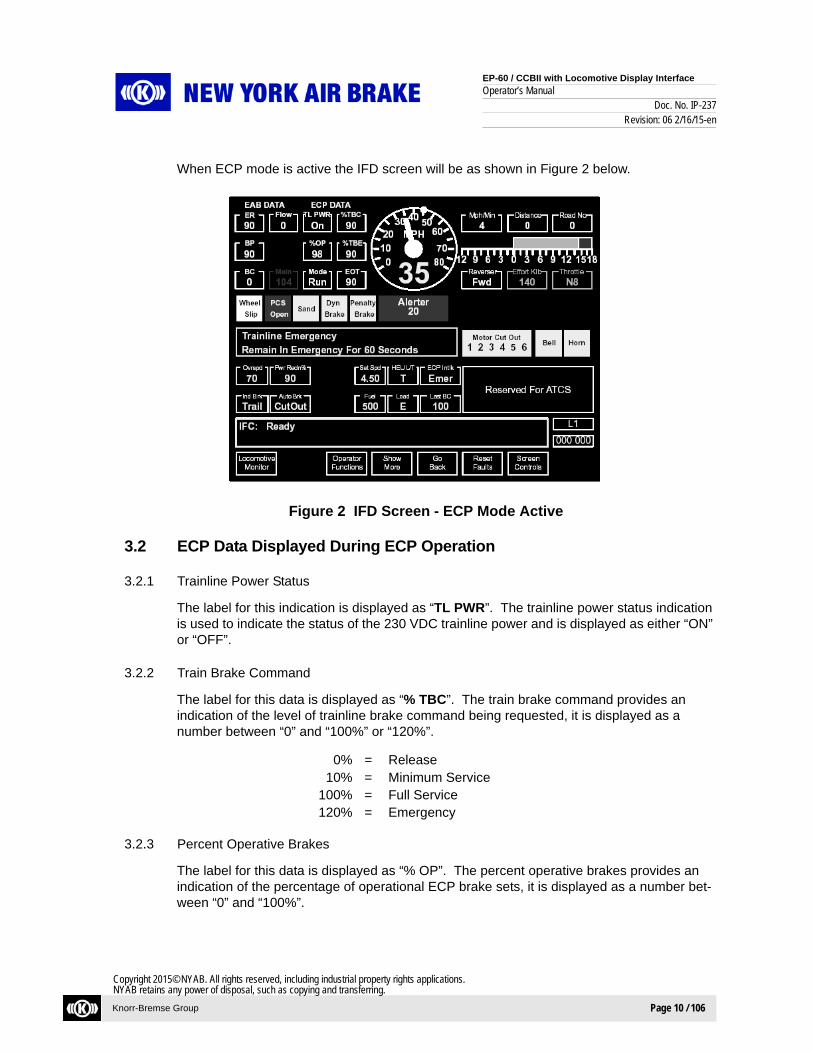
When ECP mode is active the IFD screen will be as shown in Figure 2 below.
Figure 2 IFD Screen - ECP Mode Active
3.2 ECP Data Displayed During ECP Operation
3.2.1 Trainline Power Status
The label for this indication is displayed as “TL PWR”. The trainline power status indication is used to indicate the status of the 230 VDC trainline power and is displayed as either “ON” or “OFF”.
3.2.2 Train Brake Command
The label for this data is displayed as “% TBC”. The train brake command provides an indication of the level of trainline brake command being requested, it is displayed as a number between “0” and “100%” or “120%”.
0% = Release10% = Minimum Service
100% = Full Service120% = Emergency
3.2.3 Percent Operative Brakes
The label for this data is displayed as “% OP”. The percent operative brakes provides an indication of the percentage of operational ECP brake sets, it is displayed as a number bet-ween “0” and “100%”.

EP-60 / CCBII with Locomotive Display Interface
Operator’s ManualDoc. No. IP-237
Revision: 06 2/16/15-en
Knorr-Bremse Group Page 11 / 106
Copyright 2015© NYAB. All rights reserved, including industrial property rights applications.NYAB retains any power of disposal, such as copying and transferring.
3.2.4 Train Brake Effort
The label for this data is displayed as “% TBE”. The train brake effort provides an indication of the level of trainline brake command being reported as feedback from the CCDs. It is dis-played as a number between “0” and “120%”.
3.2.5 ECP System Mode
The label for this data is displayed as “MODE”. The mode is displayed as “INIT”, “RUN”, “SWITCH” or “CUTOUT”.
3.2.6 End-of-Train Brake Pipe Pressure (from the ECP EOT)
The label for this data is displayed as “EOT”. The value of the brake pipe pressure reported by the ECP EOT is displayed as a number between “0” and “250” PSI.
3.2.7 HEU Lead / Trail Status
The label for this data is displayed as “HEU L/T”. The Head End Unit status provides the ECP Lead / Trail / Remote status of the locomotive. It is displayed as “L” (ECP Lead), “T” (ECP Trail) or “R” (ECP Remote). This is NOT to be confused with the Air Brake lead or trail setting.
3.2.8 ECP Brake Interlock Status
The label for this indication is displayed as “ECP INTLK”. This provides an indication that the ECP system is commanding an ECP brake interlock, it is displayed as is either “OFF”, “FS” or “EMER”. FS represents full service and EMER stands for emergency.
3.2.9 Train Empty / Load
The label for this data is displayed as “LOAD”. This provides an indication of the train’s empty or loaded condition. It is displayed as “E” (for empty load), or “L” (for loaded).
ECP Set-up and other functions are performed by using an ECP remote sessions on the IFD. The following is the main screen of the ECP remote sessions (Figure 3).

EP-60 / CCBII with Locomotive Display Interface
Operator’s ManualDoc. No. IP-237
Revision: 06 2/16/15-en
Knorr-Bremse Group Page 12 / 106
Copyright 2015© NYAB. All rights reserved, including industrial property rights applications.NYAB retains any power of disposal, such as copying and transferring.
Figure 3 ECP Main Remote Sessions Screen
Function Keys
RUN - Requests LEAD / RUN / AUTO (see section 5.1)SWITCH - Requests LEAD / SWITCH / AUTO (see section 5.7)SET LOAD - Activates the SET LOAD screen (see section 5.3)POWER ON/OFF - Requests Power to AUTO or OFF (see section 5.3)END ECP - Requests ENDING ECP (see section 5.6)ECP AUX MENU - Activates the ECP Auxiliary Menu screen (see section 5.10)EXIT - Terminates Remote Session, This key is always displayed
and controlled by the IFD
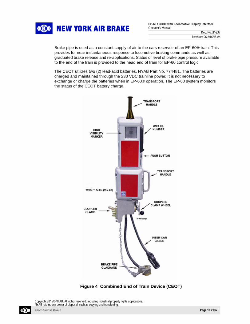
3.3 Combined End Of Train (CEOT)
The Combined End Of Train Device (CEOT) is a self contained, portable device that is moved and placed on the coupler of the last car making up an ECP equipped train. It is iden-tified as the last device within the train. It occupies the Inter Car Cable connector and brake pipe connection of the car, therefore further cars could not be connected.
The CEOT uses trainline power to charge its batteries and to supply power to its electronics. The CEOT derives its power from the batteries in the absence of trainline power. Commu-nication is available when 230 VDC trainline power is active and also when it is not active. The CEOT generates a ‘beacon’ message transmitted throughout the train as an indication of trainline communication integrity. Status of level of trainline power available to the end of the train is provided to the head end of train for EP-60® control logic.
ECP BRAKE SYSTEM
RUN
RUN - Enter ECP Run ModeSWITCH - Enter ECP Switch ModeSET LOAD - Set Train Empty/LoadPOWER ON/OFF - Trainline Power ON/OFFEND ECP - Set ECP Cut-out and TrailECP AUX MENU - Other ECP Functions
SWITCH SETLOAD
POWERON/OFF
ENDECP
ECP AUXMENU
EXIT
MAIN OPERATING MENUScreen header
Screen name
Menu optiondescription
Menu options
Function Keys
EP-60 / CCBII with Locomotive Display Interface
Operator’s ManualDoc. No. IP-237
Revision: 06 2/16/15-en
Knorr-Bremse Group Page 13 / 106
Copyright 2015© NYAB. All rights reserved, including industrial property rights applications.NYAB retains any power of disposal, such as copying and transferring.
Brake pipe is used as a constant supply of air to the cars reservoir of an EP-60® train. This provides for near instantaneous response to locomotive braking commands as well as graduated brake release and re-applications. Status of level of brake pipe pressure available to the end of the train is provided to the head end of train for EP-60 control logic.
The CEOT utilizes two (2) lead-acid batteries, NYAB Part No. 774481. The batteries are charged and maintained through the 230 VDC trainline power. It is not necessary to exchange or charge the batteries when in EP-60® operation. The EP-60 system monitors the status of the CEOT battery charge.
Figure 4 Combined End of Train Device (CEOT)

EP-60 / CCBII with Locomotive Display Interface
Operator’s ManualDoc. No. IP-237
Revision: 06 2/16/15-en
Knorr-Bremse Group Page 14 / 106
Copyright 2015© NYAB. All rights reserved, including industrial property rights applications.NYAB retains any power of disposal, such as copying and transferring.
3.3.1 Installation
3.3.1.1 Assure that ECP Trainline Power is not applied (ON).
3.3.1.2 Locate Coupler Clamp Mounting Position on coupler of last car in ECP equipped train as shown in Figure 5.
Figure 5 Coupler Clamp Mounting Position
3.3.1.3 Release Clamp Lock. Turn Coupler Clamp Wheel counter-clockwise to fully extend finger to perpendicular position (against stop). Refer to Figure 6. Then set the Clamp Lock.
Figure 6 Clamp Lock in Unlocked Position
COUPLER CLAMPMOUNTING POSITION
INTER-CAR CABLEand CONNECTOR
BRAKE PIPE END HOSE

EP-60 / CCBII with Locomotive Display Interface
Operator’s ManualDoc. No. IP-237
Revision: 06 2/16/15-en
Knorr-Bremse Group Page 15 / 106
Copyright 2015© NYAB. All rights reserved, including industrial property rights applications.NYAB retains any power of disposal, such as copying and transferring.
3.3.1.4 Set CEOT Clamp onto coupler with Finger extending into the upper clevis of the mounting position. Turn Coupler Clamp Wheel clockwise to secure (See Figure 7).
Figure 7 CEOT Clamped onto Coupler
The CEOT may require jostling as coupler clamp wheel is tightened to assure unit is secure. Assure that wheel is seated with clamp lock as anti rotation protection.
3.3.1.5 Secure with optional padlock with clasp through wheel and lock.
3.3.1.6 Connect CEOT Gladhand to BP End Hose and open BP End Valve.
3.3.1.7 Connect CEOT Trainline Cable to Inter-Car Cable.
NOTEIf brake pipe pressure is present the CEOT may activate the High Visibility Marker if ambient light conditions justify.

EP-60 / CCBII with Locomotive Display Interface
Operator’s ManualDoc. No. IP-237
Revision: 06 2/16/15-en
Knorr-Bremse Group Page 16 / 106
Copyright 2015© NYAB. All rights reserved, including industrial property rights applications.NYAB retains any power of disposal, such as copying and transferring.
Figure 8 Mounted CEOT
3.3.2 Removal
3.3.2.1 Assure ECP Trainline Power is OFF.
3.3.2.2 Disconnect CEOT Trainline Cable from Inter Car Cable.
3.3.2.3 Close car’s brake pipe end valve.
3.3.2.4 Depress Pressure Relief Valve located on the CEOT Gladhand until all air has been allowed to exhaust.
3.3.2.5 Disconnect CEOT gladhand from brake pipe end hose.
WARNINGSerious injury could occur if power is not removed.
WARNINGSerious injury could occur if pressure is not removed.

EP-60 / CCBII with Locomotive Display Interface
Operator’s ManualDoc. No. IP-237
Revision: 06 2/16/15-en
Knorr-Bremse Group Page 17 / 106
Copyright 2015© NYAB. All rights reserved, including industrial property rights applications.NYAB retains any power of disposal, such as copying and transferring.
3.3.2.6 Remove optional padlock clasp from Coupler Clamp Wheel and Clamp Lock.
3.3.2.7 Release Clamp Lock by pulling downward.
3.3.2.8 Supporting CEOT, turn Coupler Clamp Wheel counter-clockwise to release Finger from clevis of coupler.
3.3.2.9 Set unit on back or side for transport.
3.3.3 Activation
3.3.3.1 The CEOT will activate on the application of ECP Trainline Power to:a) Send its trainline-wire communicated EOT Beacon with status information.b) Brake pipe pressure from CEOT will be invalid (- - - - display) until pressure greater
than ~70 kPa (10 psi) is applied.
3.3.3.2 The CEOT will activate on the application of brake pipe pressure greater than ~70 kPa (10 psi) to:a) Flash the High Visibility Marker if ambient light conditions warrant.b) Initiate optional RF communications.
3.3.3.3 The CEOT will activate on two (2) Test Pushbutton presses to:a) Send its trainline-wire communicated EOT Beacon with status information.b) Flash the High Visibility Marker if ambient light conditions warrant.c) Initiate optional RF communications.
3.3.4 De-Activation
3.3.4.1 The CEOT will de-activate immediately on loss of ECP Trainline Power, combined with loss of HEU (Head End Unit) Beacon, when accompanied with an ECP “CUT OUT” to:
a) Stop sending its trainline-wire communicated EOT Beacon.
3.3.4.2 The CEOT will de-activate in one (1) hour on loss of ECP Trainline Power, combined with loss of HEU Beacon, when not accompanied with an ECP “CUT OUT” to:a) Stop sending its trainline-wire communicated EOT Beacon
3.3.4.3 The CEOT will not de-activate on loss of ECP Trainline Power with an HEU Beacon until “Low Battery” detection (4+ hours minimum from charged condition).
NOTEHigh Visibility Marker is set to off by an internal level switch.

EP-60 / CCBII with Locomotive Display Interface
Operator’s ManualDoc. No. IP-237
Revision: 06 2/16/15-en
Knorr-Bremse Group Page 18 / 106
Copyright 2015© NYAB. All rights reserved, including industrial property rights applications.NYAB retains any power of disposal, such as copying and transferring.
3.3.4.4 The CEOT will not de-activate with ECP Trainline Power applied.
3.3.4.5 The CEOT will de-activate optional RF communications in five (5) minutes from when brake pipe trainline is reduced to less than ~35 kPa (5 psi) combined with ending of its trainline-wire communicated EOT Beacon.
3.3.4.6 The CEOT will de-activate its High Visibility Marker when:a) Ambient light conditions do not warrant operation.b) CEOT is removed from coupler (tilt).c) Battery(s) power is sufficiently reduced (>12 hours).
EP-60 / CCBII with Locomotive Display Interface
Operator’s ManualDoc. No. IP-237
Revision: 06 2/16/15-en
Knorr-Bremse Group Page 19 / 106
Copyright 2015© NYAB. All rights reserved, including industrial property rights applications.NYAB retains any power of disposal, such as copying and transferring.
The following set – up guide is a quick reference to set-up an EP-60 Trainline. A full overview of this section is repeated again in more detail under 5.0 ECP System Operation.
4.1 EP-60 Trainline Set-Up
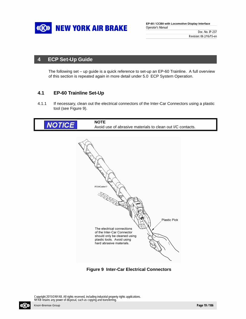
4.1.1 If necessary, clean out the electrical connectors of the Inter-Car Connectors using a plastic tool (see Figure 9).
Figure 9 Inter-Car Electrical Connectors
4 ECP Set-Up Guide
NOTEAvoid use of abrasive materials to clean out I/C contacts.
EP-60 / CCBII with Locomotive Display Interface
Operator’s ManualDoc. No. IP-237
Revision: 06 2/16/15-en
Knorr-Bremse Group Page 20 / 106
Copyright 2015© NYAB. All rights reserved, including industrial property rights applications.NYAB retains any power of disposal, such as copying and transferring.
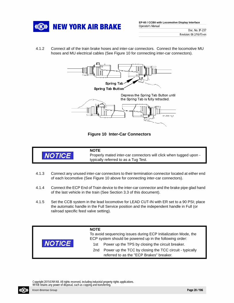
4.1.2 Connect all of the train brake hoses and inter-car connectors. Connect the locomotive MU hoses and MU electrical cables (See Figure 10 for connecting inter-car connectors).
Figure 10 Inter-Car Connectors
4.1.3 Connect any unused inter-car connectors to their termination connector located at either end of each locomotive (See Figure 10 above for connecting inter-car connectors).
4.1.4 Connect the ECP End of Train device to the inter-car connector and the brake pipe glad hand of the last vehicle in the train (See Section 3.3 of this document).
4.1.5 Set the CCB system in the lead locomotive for LEAD CUT-IN with ER set to a 90 PSI; place the automatic handle in the Full Service position and the independent handle in Full (or railroad specific feed valve setting).
NOTEProperly mated inter-car connectors will click when tugged upon - typically referred to as a Tug Test.
NOTETo avoid sequencing issues during ECP Initialization Mode, the ECP system should be powered up in the following order:
1st Power up the TPS by closing the circuit breaker.
2nd Power up the TCC by closing the TCC circuit - typically referred to as the "ECP Brakes" breaker.

EP-60 / CCBII with Locomotive Display Interface
Operator’s ManualDoc. No. IP-237
Revision: 06 2/16/15-en
Knorr-Bremse Group Page 21 / 106
Copyright 2015© NYAB. All rights reserved, including industrial property rights applications.NYAB retains any power of disposal, such as copying and transferring.
4.1.6 The main circuit breakers for the Trainline Power Supply (TPS), and the Trainline Communications Controller (TCC) should be in the “ON” position. The TPS is typically referred to as the "ECP 230 VDC TRAINLINE POWER". The TCC breaker is typically referred to as the “ECP Brake System”.
4.1.7 The trailing locomotives in the ECP train are to be operated as follows:
4.1.8 Set the CCB system in the trailing locomotive(s) for TRAIL operation as normally done in conventional CCB TRAIL mode operation. Next FIRST turn on the circuit breaker for the trainline power supply (TPS), this may be labeled “ECP 230 VDC TRAINLINE POWER”. SECOND, turn on the circuit breaker for the trainline communications controller (TCC), this may be labeled ECP COMM CONTROLLER. The TCC will power-up and default to ECP TRAIL.
NOTEOnce the ECP trainline becomes active (from the Lead locomotive), the trailing locomotive’s system automatically enters ECP trail mode and begins responding to trainline commands. ECP data will be displayed on the trailing locomotive’s main screen display.
NOTEThe ECP system can be operated with multiple trainline power sup-plies at the same time. The TCC(s) on the trailing locomotives need to be turned ON in order for those locomotives to be included during train sequencing.
NOTEECP set-up and other functions are performed by using an ECP remote sessions on the IFD display. When a locomotive alarm occurs, the IFC terminates the ECP Remote Sessions that are running. If this occurs it is necessary to acknowledge the alarm and re-enter the ECP remote sessions.

EP-60 / CCBII with Locomotive Display Interface
Operator’s ManualDoc. No. IP-237
Revision: 06 2/16/15-en
Knorr-Bremse Group Page 22 / 106
Copyright 2015© NYAB. All rights reserved, including industrial property rights applications.NYAB retains any power of disposal, such as copying and transferring.
4.2 ECP Run Mode
4.2.1 Place the INDEPENDENT handle in FULL. Press the Operator Functions key, and then press the Air Brake key. Press the ECP key.
4.2.2 Press the RUN key.
4.2.3 If the train is in the LOADED condition, press the ACCEPT key. The ECP gage LOAD will be L. The train is now set to the LOADED condition.
4.2.4 If the train is in the EMPTY condition, press the CHANGE LOAD key.
4.2.5 Press the CONFIRM LOAD key.
4.2.6 Press the ACCEPT key.
4.2.7 Press the EXECUTE key. The system will command a full-service (100%) train brake interlock.
4.2.8 Unless already there, place the AUTOMATIC handle to RELEASE in order to charge the brake pipe.
4.2.9 Verify that the correct number of locomotives, power supplies, cars, CCDs and EOT are found as displayed on the make up screen. To ensure the correct percent Operable Brake (%OP) is reported to the head end, increase the number of cars to match the trains consist during make up if a discrepancy exists.
WARNINGThe train load must be set the same as the load condition of the cars (Empty or Loaded) in order to obtain the correct amount of braking to stop the train. Set the load to either empty or loaded.
Failure to observe these safety precautions can lead to injury or death.
WARNINGWhen the execute key is pressed 230 VDC will be applied to the trainline. Verify that all personnel are clear of the train’s ECP inter-car connectors before pressing the execute key.
Failure to observe these safety precautions can lead to injury or death.
EP-60 / CCBII with Locomotive Display Interface
Operator’s ManualDoc. No. IP-237
Revision: 06 2/16/15-en
Knorr-Bremse Group Page 23 / 106
Copyright 2015© NYAB. All rights reserved, including industrial property rights applications.NYAB retains any power of disposal, such as copying and transferring.
4.2.10 Press the ACCEPT key.
4.2.11 Press the START SEQUENCE key and wait until the system completes sequencing.
4.2.12 The percent operable brake sets (%OP) will start to increase.
The system requires at least 85% operable in order to proceed past this step. If the percent operable remains less than 85%:
- Car reservoir pressures may be too low, allow the train to charge.- CCD battery charges may be too low, allow the batteries to charge.
(Also see section 5.10.4.3 a CCD/EOT battery test can be performed to determine which cars have low battery).
Once percent operative brake is determined, a crew message may be displayed indicating what is required to enter RUN Mode:
- Low EOT Brake Pipe Pressure- Low EOT Battery Charge- Automatic Handle must be placed in the FULL SERVICE position.
4.2.13 Move the AUTOMATIC brake handle to FULL SERVICE, the following crew message is displayed:
TRAIN LOAD CURRENTLY SET TO EMPTY/LOADED (Pending load condition)
4.2.14 The train can now be controlled using ECP brake control. If desired to release the train brakes, move the AUTOMATIC handle to RELEASE.
4.2.15 If desired to release the locomotive brakes, move the INDEPENDENT handle to RELEASE.
4.3 Set Trainline Empty / Load Setting
4.3.1 Press the ECP MAIN MENU key. Press the SET LOAD key.
NOTEThe required train brake departure test(s) should be performed prior to operating the train as governed by regulation and the railroad in which the train is operating under: these may include a brake pipe leakage test and a brake application and release test.
CAUTIONIt is very important to correctly set the ECP system for the car’sEMPTY or LOAD weight condition. All of the car’s CCDs will pro-vide braking based on this information. Setting the Load incorrectly can result in either over-braking or under-braking the train.

EP-60 / CCBII with Locomotive Display Interface
Operator’s ManualDoc. No. IP-237
Revision: 06 2/16/15-en
Knorr-Bremse Group Page 24 / 106
Copyright 2015© NYAB. All rights reserved, including industrial property rights applications.NYAB retains any power of disposal, such as copying and transferring.
4.3.2 IF all the cars in the train are EMPTY set the train load setting to EMPTY by:
4.3.3 Press the CHANGE LOAD key and EMPTY will be displayed and highlighted. Press the CONFIRM LOAD key and EMPTY will be displayed and highlighted. Press the ACCEPT key. The train is now set to the EMPTY condition. Note that the Empty/Load gage on the screen shows that the setting is EMPTY.
IF all the cars in the train are LOADED (as it would be at a mine for example) set the train load setting to LOADED by:
4.3.4 Press the CHANGE LOAD key and LOADED will be displayed and highlighted. Press the CONFIRM LOAD key and LOADED will be displayed and highlighted. Press the ACCEPT key. The train is now set to the LOADED condition. Note that the Empty/Load gage on the screen shows that the setting is LOADED.
4.4 ECP SWITCH MODE
4.4.1 Switching To ECP SWITCH MODE:
4.4.2 SWITCH mode can be used for performing switching operations and where the use of an ECP end-of-train device is not practical. The system can continue to operate in SWITCH mode without an ECP EOT, this will cause trainline power to be shutdown.
4.4.3 The percent operative brakes are not known when in SWITCH mode and speed is limited to 20 MPH. Before moving the train in SWITCH mode, ensure that a sufficient number of CCDs are functioning in order to provide the required amount of braking. A means to verify this would be to make an ECP brake application and physically inspect the cars for a brake application.
4.4.4 Place the INDEPENDENT handle in FULL. Press the Operator Functions key, and then press the Air Brake key. Press the ECP key.
4.4.5 From the ECP MAIN MENU. Press the SWITCH key.
4.4.6 If the train is in the LOADED condition, press the ACCEPT key. The ECP gage LOAD will be L. The train is now set to the LOADED condition.
4.4.7 If the train is in the EMPTY condition, press the CHANGE LOAD key.
4.4.8 Press the CONFIRM LOAD key.
4.4.9 Press the ACCEPT key.
WARNINGWhen the execute key is pressed 230 VDC will be applied to the trainline. Verify that all personnel are clear of the train’s ECP inter-car connectors before pressing the EXECUTE key.
Failure to observe these safety precautions can lead to injury or death.

EP-60 / CCBII with Locomotive Display Interface
Operator’s ManualDoc. No. IP-237
Revision: 06 2/16/15-en
Knorr-Bremse Group Page 25 / 106
Copyright 2015© NYAB. All rights reserved, including industrial property rights applications.NYAB retains any power of disposal, such as copying and transferring.
4.4.10 Press the EXECUTE key. The following crew messages are displayed:
ACTIVATING TRAINLINE POWER
ECP SWITCH MODE SPEED LIMIT
If there is no ECP EOT or NYAB TILTD Device then trainline power will be shutdown after approximately 8 seconds.
The ECP system is now in SWITCH mode.
Refer to section 5.6 or 5.7 for information about ending ECP and changing to conventional pneumatic brake control.
Refer to section 5.1 for information about entering ECP RUN mode.
4.5 End ECP (*Changing from ECP to Conventional Pneumatic Brake Control) *Does not include system with "End ECP in Emergency" feature.
4.5.1 These steps need to be followed in order to exit ECP operation (RUN or SWITCH) and change to conventional pneumatic brake control. This would also be done when it is desired to leave the ECP train brakes released when the locomotives are uncoupled from the train, such as when the locomotives are uncoupled from the train and leaving it to be unloaded at an unloading site.
4.5.2 Once these steps are completed the locomotive’s brake system will provide conventional pneumatic brake control (ER and BP will respond corresponding to automatic handle position). The only braking available on the cars with Stand-alone CCD’s, is the CCD pneumatic back-up brake which will release the brake if brake pipe is charged to 90 PSI or apply the brake only if brake pipe is vented to zero (0).
4.5.3 Place the INDEPENDENT handle in FULL. Press the Operator Functions key, and then press the Air Brake key. Press the ECP key.
4.5.4 From the ECP MAIN MENU. Press the END ECP key and the crew message PNEUMATIC BRAKE ACTIVE is displayed.
WARNINGThe train load must be set the same as the load condition of the cars (empty or loaded) in order to obtain the correct amount of brak-ing to stop the train. Set the load to either EMPTY or LOADED.
Failure to observe these safety precautions can lead to injury or death.
NOTEThe EBV display no longer displays the ECP Train Brake Call and it now shows the target ER pressure.

EP-60 / CCBII with Locomotive Display Interface
Operator’s ManualDoc. No. IP-237
Revision: 06 2/16/15-en
Knorr-Bremse Group Page 26 / 106
Copyright 2015© NYAB. All rights reserved, including industrial property rights applications.NYAB retains any power of disposal, such as copying and transferring.
4.5.5 Move the automatic handle to any desired position, ER and BP will now respond based on the AUTOMATIC handle position chosen.
4.5.6 Press the EXECUTE key. ECP is now inactive. All of the cars now have cut-out the ECP brake and the trainline 230 VDC power is turned OFF.
4.6 END ECP (*Changing From ECP TO Conventional Pneumatic Brake Control) *For systems with "End ECP in Emergency" feature.
These steps need to be followed in order to exit ECP operation (RUN or SWITCH) and change to conventional pneumatic brake control. This would also be done when it is desired to leave the ECP train brakes released when the locomotives are uncoupled from the train, such as when the locomotives are uncoupled from the train and leaving it to be unloaded at an unloading site.
Once these steps are completed the locomotive’s brake system will provide conventional pneumatic brake control (ER and BP will respond corresponding to automatic handle posi-tion). The only braking available on the cars equipped with Stand-alone CCD’s, is the CCD pneumatic back-up brake which will release the brake if brake pipe is charged to 90 PSI or apply the brake only if brake pipe is vented to zero (0).
4.6.1 ECP can be ended from the MAIN OPERATING MENU.
4.6.2 Move the independent handle to FULL.
4.6.3 Move the automatic handle to EMER and wait until the EOT field on the display reports zero (0) brake pipe pressure before proceeding.
4.6.4 Press the END ECP key and then EXECUTE. ECP mode will end but the screen will still show ECP data fields.
Note that the END ECP key is still visible in the ECP screen. The END ECP key can be used by a locomotive to shut down active CCDs in a train without the need to re-enter ECP mode.
4.6.5 Press the EXIT key to return to the pneumatic mode screen.
WARNINGWhen the EXECUTE key is pressed, all CCDs in the train will cut-out and stop responding to ECP train brake commands and release the brakes. The only train brake that is operational on the cars with stand-aloneCCDs is the CCD pneumatic back-up brake which will release the brake if brake pipe is charged to 90 PSI and apply the brake only if brake pipe is vented to zero (0).
Failure to observe these safety precautions can lead to injury or death.

EP-60 / CCBII with Locomotive Display Interface
Operator’s ManualDoc. No. IP-237
Revision: 06 2/16/15-en
Knorr-Bremse Group Page 27 / 106
Copyright 2015© NYAB. All rights reserved, including industrial property rights applications.NYAB retains any power of disposal, such as copying and transferring.
4.7 LEDs on the CCD
There are four LED's on the CCD's front face. These provide local operating status pertaining to Trainline power, HEU communication, brake-applied status, and CCD health.
PWR LED (Red or Green): OFF = CCD shut downGreen = CCD under battery power Red = CCD receiving 230 VDC trainline power Flashing = Battery voltage is low
BRK LED (Green):OFF = Brakes ReleasedGreen = Brakes AppliedFlashing= CCD is Cut-Out (ECP)
COM LED (Green): OFF = No communication signal received from the HEU Flashing = Communications signal is received from the HEUSolid = Emulation Mode
FLT LED (Red):OFF = OKRed = Active Fault(s)
Two circular connectors (J1) and (J2) are provided on the front of the CCD. The connector on the left side of the front face (J1) is for connecting to the trainline cable / car identification module (IDM). The circular connector on the right side of the front face (J2) is for a local power and communications network interface for the add-on capability of any potential future "Smart Car" technologies (see Figure 11).
Figure 11 CCD LED Status

EP-60 / CCBII with Locomotive Display Interface
Operator’s ManualDoc. No. IP-237
Revision: 06 2/16/15-en
Knorr-Bremse Group Page 28 / 106
Copyright 2015© NYAB. All rights reserved, including industrial property rights applications.NYAB retains any power of disposal, such as copying and transferring.
5.1 Normal Operation / ECP Run Mode
5.1.1 Set-Up Procedure
5.1.1.1 Connect all of the train brake hoses and inter-car connectors together.
5.1.1.2 Connect the unused inter-car connectors to their termination connector on both ends of each locomotive.
5.1.1.3 Connect the ECP End-of-train device to the inter-car connector and brake pipe glad hand of the last vehicle in the train as outlined in Section 3.3 of this document.
5.1.1.4 If an Emergency condition hasn’t been reset after performing a CCB SELF TEST the Automatic handle must be placed into Emergency and then Release. Emergency will reset once ER has charged.
5.1.1.5 In order to set up the locomotive for ECP brake control the CCB must be set to Lead cut-in with ER set to 90 PSI (This is the recommended ER setting for ECP operation, although the system will allow an ER value within the range of 60-110 PSI. Place the automatic handle in any desired service position and the independent handle in Full.
5.1.1.6 FIRST turn on the circuit breaker for the trainline power supply TPS), this may be labeled “ECP 230 VDC TRAINLINE POWER”. SECOND, turn on the circuit breaker for the trainline communications controller (TCC), this may be labeled ECP COMM CONTROLLER.
5.1.1.7 The trailing locomotives in the ECP train are to be operated as follows.
Set the CCB system in the trailing locomotive(s) for TRAIL operation as normally done in conventional CCB TRAIL mode operation. Next, FIRST turn on the circuit breaker for the trainline power supply (TPS), this may be labeled “ECP 230 VDC TRAINLINE
5 ECP System Operation
WARNINGMake sure that the 230 VDC trainline power is off before connecting the inter-car connectors.
Failure to observe these safety precautions can lead to injury or death.
NOTEThe LED on the front face of the TCC must also be ON (illuminated "RED").

EP-60 / CCBII with Locomotive Display Interface
Operator’s ManualDoc. No. IP-237
Revision: 06 2/16/15-en
Knorr-Bremse Group Page 29 / 106
Copyright 2015© NYAB. All rights reserved, including industrial property rights applications.NYAB retains any power of disposal, such as copying and transferring.
POWER”. SECOND, turn on the circuit breaker for the trainline communications cont-roller (TCC), this may be labeled ECP COMM CONTROLLER. The TCC will power-up and default to ECP TRAIL.
5.1.2 Place the INDEPENDENT handle in FULL. Press the Operator Functions key, and then press the Air Brake key. Press the ECP key. The following remote session’s ECP Main Operating Menu screen will be displayed (Figure 12). Press the RUN key.
Figure 12 Main Operating Screen
NOTEOnce the ECP trainline becomes active (from the Lead locomotive), the trailing locomotive’s system automatically enters ECP trail mode and begins responding to trainline commands. ECP data will be displayed on the trailing locomotive’s main screen display.
NOTEThe ECP system can be operated with multiple trainline power sup-plies at the same time. The TCC(s) on the trailing locomotives need to be turned ON in order for those locomotives to be included during train sequencing.
NOTEECP set-up and other functions are performed by using an ECP remote sessions on the IFD display. When a locomotive alarm occurs, the IFC terminates the ECP Remote Sessions that are running. If this occurs it is necessary to acknowledge the alarm and re-enter the ECP remote sessions.
ECP BRAKE SYSTEM
RUN
RUN - Enter ECP Run ModeSWITCH - Enter ECP Switch ModeSET LOAD - Set Train Empty/LoadPOWER ON/OFF - Trainline Power ON/OFFEND ECP - Set ECP Cut-out and TrailECP AUX MENU - Other ECP Functions
SWITCH SETLOAD
POWERON/OFF
ENDECP
ECP AUXMENU
EXIT
MAIN OPERATING MENU

EP-60 / CCBII with Locomotive Display Interface
Operator’s ManualDoc. No. IP-237
Revision: 06 2/16/15-en
Knorr-Bremse Group Page 30 / 106
Copyright 2015© NYAB. All rights reserved, including industrial property rights applications.NYAB retains any power of disposal, such as copying and transferring.
5.1.3 The following screen is displayed (Figure 13):
Figure 13 Set Load
5.1.4 If the train is in the LOADED condition, press the ACCEPT key. The ECP gage LOAD will be L. The train is now set to the LOADED condition.
5.1.5 If the train is in the EMPTY condition, press the CHANGE LOAD key and the screen changes to (Figure 14):
Figure 14 Set Load - Change Load
WARNINGThe train load must be set the same as the load condition of the cars (Empty or Loaded) in order to obtain the correct amount of braking to stop the train. Set the load to either empty or loaded.
Failure to observe these safety precautions can lead to injury or death.
ECP BRAKE SYSTEM
SET LOAD
ECP MAINMENU
EXIT
<== New<== CurrentLOADED
LOADED
ACCEPTCHANGELOAD
ECP BRAKE SYSTEM
SET LOAD
ECP MAINMENU
EXIT
<== New<== CurrentLOADED LOADED
EMPTY
CONFIRMLOAD
LOADED

EP-60 / CCBII with Locomotive Display Interface
Operator’s ManualDoc. No. IP-237
Revision: 06 2/16/15-en
Knorr-Bremse Group Page 31 / 106
Copyright 2015© NYAB. All rights reserved, including industrial property rights applications.NYAB retains any power of disposal, such as copying and transferring.
5.1.6 Press the CONFIRM LOAD key and the screen changes to (Figure 15):
Figure 15 Set Load - Confirm Load
5.1.7 Press the ACCEPT key and the screen changes to (Figure 16):
Figure 16 Main Operating Screen - Run
WARNINGWhen the execute key is pressed, 230 VDC will be applied to the trainline. Verify that all personnel are clear of the train’s ECP inter-car connectors before pressing the EXECUTE key.
Failure to observe these safety precautions can lead to injury or death.
ECP BRAKE SYSTEM
SET LOAD
ECP MAINMENU
EXIT
<== New<== CurrentLOADED LOADED
ACCEPT
ACCEPT/EXECUTE to change
EMPTY EMPTY
ECP BRAKE SYSTEM
RUN - Enter ECP Run ModeSWITCH - Enter ECP Switch ModeSET LOAD - Set Train Empty/LoadPOWER ON/OFF - Trainline Power ON/OFFEND ECP - Set ECP Cut-out and TrailECP AUX MENU - Other ECP Functions
MAIN OPERATING MENU
No EOT - T/L power will activate
EXECUTE CANCEL EXIT

EP-60 / CCBII with Locomotive Display Interface
Operator’s ManualDoc. No. IP-237
Revision: 06 2/16/15-en
Knorr-Bremse Group Page 32 / 106
Copyright 2015© NYAB. All rights reserved, including industrial property rights applications.NYAB retains any power of disposal, such as copying and transferring.
Press the EXECUTE key. The following crew messages are displayed;
ACTIVATING TRAINLINE POWER
ECP PENALTY – INITIALIZATION MODE ACTIVE, MAKEUP REQUIRED TO ENTER RUN MODE
Unless already there, move the AUTOMATIC handle to RELEASE in order to charge the brake pipe.
Once the system completes a train makeup, the screen changes to (Figure 17):
Figure 17 Train Makeup
5.1.8 Verify that the correct number of locomotives and cars are found.
If the correct number of vehicles is not displayed the operator is provided with a means to manually adjust it, it can be increased using the INCREASE button. If the INCEASE button is pressed the “Total ECP brake sets” will increase. Note that this will cause the percent operable to be less than 100%. If the INCREASE button is pressed a DECREASE button will be displayed next to it in order to manually decrease the number of vehicles.
Press the ACCEPT key and the screen will change to (Figure 18);
NOTEUpon entering Initialization Mode a 100% brake application will be applied until the train has been properly set-up to "ECP RUN MODE ENABLED".
ECP BRAKE SYSTEM
TRAIN MAKEUP
ECP Locos: ECP Power Supplies:ECP Cars: ECP CCDs:ECP EOT:
TOTAL ECP BRAKE SETS =
Train Sequenced:
INCREASE ACCEPT REJECT EXIT
21701
2170
No
170
Change and/or accept total brake sets

EP-60 / CCBII with Locomotive Display Interface
Operator’s ManualDoc. No. IP-237
Revision: 06 2/16/15-en
Knorr-Bremse Group Page 33 / 106
Copyright 2015© NYAB. All rights reserved, including industrial property rights applications.NYAB retains any power of disposal, such as copying and transferring.
Figure 18 Train Makeup - Accept
5.1.9 The actual order of the ECP vehicles can be determined by the ECP system by pressing the START SEQUENCE key. If this is NOT desired, press the SKIP SEQUENCE key and go to step 5.1.11.
Press the START SEQUENCE key and the following operator prompts are displayed:
INITIATING SEQUENCE
ACTIVATING 24 V T/L POWER
Figure 19 Train Makeup – Sequencing in Progress
ECP PENALTY – INITIALIZATION MODE ACTIVE, VERFYING % OP BRAKE SETS
NOTEIt is not required to complete train sequencing in order to operate the ECP system.
ECP BRAKE SYSTEM
TRAIN MAKEUP
ECP Locos: ECP Power Supplies:ECP Cars: ECP CCDs:ECP EOT:
TOTAL ECP BRAKE SETS =
Train Sequenced:
CANCEL EXIT
Sequencing in progress: 5% complete
170
17022
1170
No
ECP BRAKE SYSTEM
TRAIN MAKEUP
ECP Locos: ECP Power Supplies:ECP Cars: ECP CCDs:ECP EOT:
TOTAL ECP BRAKE SETS =
Train Sequenced:
STARTSEQUENCE
SKIPSEQUENCE
EXIT
START or SKIP train sequencing
21701
2
170
170
No
EP-60 / CCBII with Locomotive Display Interface
Operator’s ManualDoc. No. IP-237
Revision: 06 2/16/15-en
Knorr-Bremse Group Page 34 / 106
Copyright 2015© NYAB. All rights reserved, including industrial property rights applications.NYAB retains any power of disposal, such as copying and transferring.
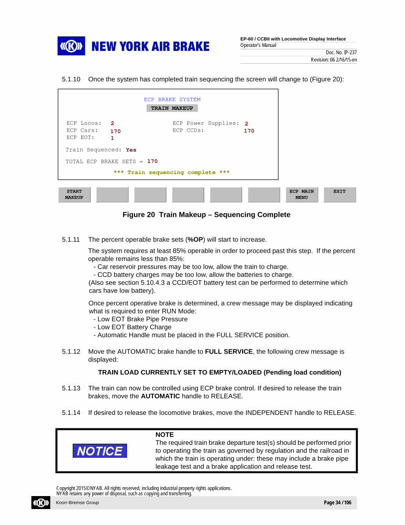
5.1.10 Once the system has completed train sequencing the screen will change to (Figure 20):
Figure 20 Train Makeup – Sequencing Complete
5.1.11 The percent operable brake sets (%OP) will start to increase.
The system requires at least 85% operable in order to proceed past this step. If the percent operable remains less than 85%:
- Car reservoir pressures may be too low, allow the train to charge.- CCD battery charges may be too low, allow the batteries to charge.
(Also see section 5.10.4.3 a CCD/EOT battery test can be performed to determine which cars have low battery).
Once percent operative brake is determined, a crew message may be displayed indicating what is required to enter RUN Mode:
- Low EOT Brake Pipe Pressure- Low EOT Battery Charge- Automatic Handle must be placed in the FULL SERVICE position.
5.1.12 Move the AUTOMATIC brake handle to FULL SERVICE, the following crew message is displayed:
TRAIN LOAD CURRENTLY SET TO EMPTY/LOADED (Pending load condition)
5.1.13 The train can now be controlled using ECP brake control. If desired to release the train brakes, move the AUTOMATIC handle to RELEASE.
5.1.14 If desired to release the locomotive brakes, move the INDEPENDENT handle to RELEASE.
NOTEThe required train brake departure test(s) should be performed prior to operating the train as governed by regulation and the railroad in which the train is operating under: these may include a brake pipe leakage test and a brake application and release test.
ECP BRAKE SYSTEM
TRAIN MAKEUP
ECP Locos: ECP Power Supplies:ECP Cars: ECP CCDs:ECP EOT:
TOTAL ECP BRAKE SETS =
Train Sequenced:
*** Train sequencing complete ***
170
17022
1170
STARTMAKEUP
ECP MAINMENU
EXIT
Yes
EP-60 / CCBII with Locomotive Display Interface
Operator’s ManualDoc. No. IP-237
Revision: 06 2/16/15-en
Knorr-Bremse Group Page 35 / 106
Copyright 2015© NYAB. All rights reserved, including industrial property rights applications.NYAB retains any power of disposal, such as copying and transferring.
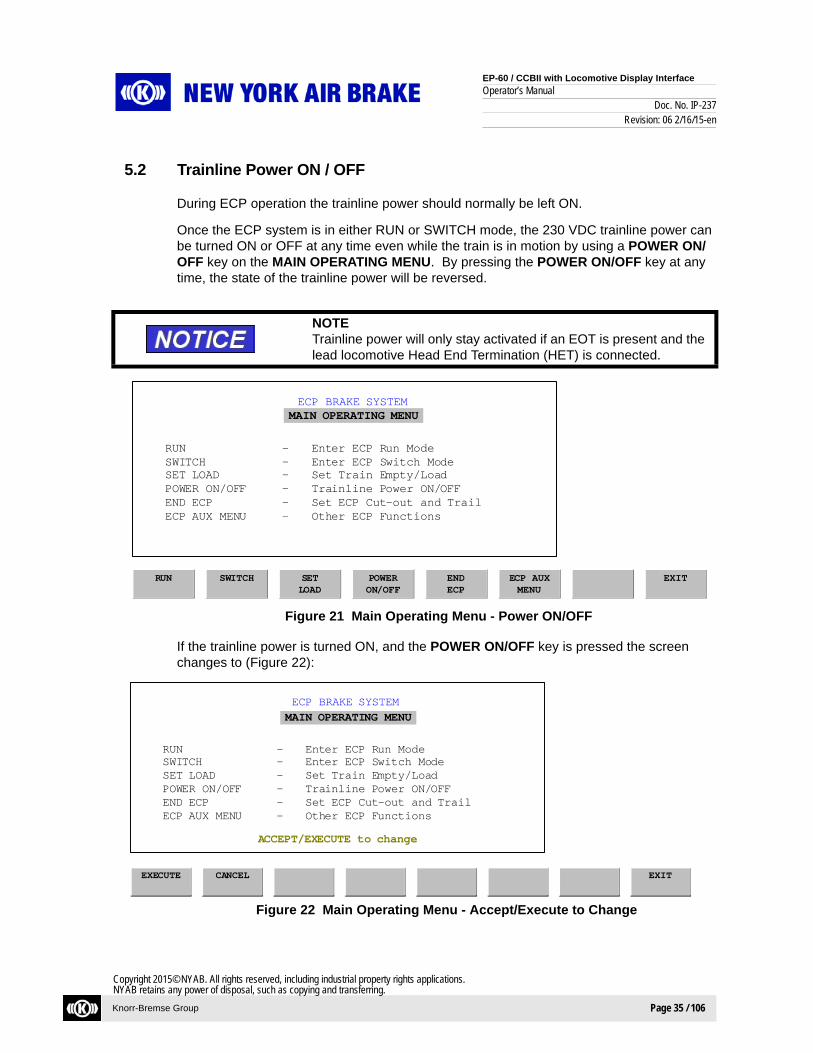
5.2 Trainline Power ON / OFF
During ECP operation the trainline power should normally be left ON.
Once the ECP system is in either RUN or SWITCH mode, the 230 VDC trainline power can be turned ON or OFF at any time even while the train is in motion by using a POWER ON/OFF key on the MAIN OPERATING MENU. By pressing the POWER ON/OFF key at any time, the state of the trainline power will be reversed.
Figure 21 Main Operating Menu - Power ON/OFF
If the trainline power is turned ON, and the POWER ON/OFF key is pressed the screen changes to (Figure 22):
Figure 22 Main Operating Menu - Accept/Execute to Change
NOTETrainline power will only stay activated if an EOT is present and the lead locomotive Head End Termination (HET) is connected.
ECP BRAKE SYSTEM
RUN
RUN - Enter ECP Run ModeSWITCH - Enter ECP Switch ModeSET LOAD - Set Train Empty/LoadPOWER ON/OFF - Trainline Power ON/OFFEND ECP - Set ECP Cut-out and TrailECP AUX MENU - Other ECP Functions
SWITCH SETLOAD
POWERON/OFF
ENDECP
ECP AUXMENU
EXIT
MAIN OPERATING MENU
ECP BRAKE SYSTEM
RUN - Enter ECP Run ModeSWITCH - Enter ECP Switch ModeSET LOAD - Set Train Empty/LoadPOWER ON/OFF - Trainline Power ON/OFFEND ECP - Set ECP Cut-out and TrailECP AUX MENU - Other ECP Functions
MAIN OPERATING MENU
EXECUTE CANCEL EXIT
ACCEPT/EXECUTE to change

EP-60 / CCBII with Locomotive Display Interface
Operator’s ManualDoc. No. IP-237
Revision: 06 2/16/15-en
Knorr-Bremse Group Page 36 / 106
Copyright 2015© NYAB. All rights reserved, including industrial property rights applications.NYAB retains any power of disposal, such as copying and transferring.
Press the EXECUTE key, the trainline power turns OFF and the TL PWR gage changes to OFF. In order to turn the trainline power ON, press the POWER ON/OFF key and the screen changes to (Figure 23):
Figure 23 Main Operating Menu – Activate Trainline Power
Press the EXECUTE key, the trainline power turns ON, the TL PWR gage changes to ON and the screen changes to (Figure 24):
Figure 24 Main Operating Menu – Setup Information
5.3 Set Load
CAUTIONIt is very important to correctly set the ECP system for the car’s EMPTY or LOAD weight condition. All of the car’s CCDs will pro-vide braking based on this information. Setting the Load incorrectly can result in either over-braking or under-braking the train.
ECP BRAKE SYSTEM
EXECUTE
RUN - Enter ECP Run ModeSWITCH - Enter ECP Switch ModeSET LOAD - Set Train Empty/LoadPOWER ON/OFF - Trainline Power ON/OFFEND ECP - Set ECP Cut-out and TrailECP AUX MENU - Other ECP Functions
CANCEL EXIT
MAIN OPERATING MENU
Trainline power will activate
ECP BRAKE SYSTEM
RUN - Enter ECP Run ModeSWITCH - Enter ECP Switch ModeSET LOAD - Set Train Empty/LoadPOWER ON/OFF - Trainline Power ON/OFFEND ECP - Set ECP Cut-out and TrailECP AUX MENU - Other ECP Functions
EXIT
MAIN OPERATING MENU
*** Setup information saved ***

EP-60 / CCBII with Locomotive Display Interface
Operator’s ManualDoc. No. IP-237
Revision: 06 2/16/15-en
Knorr-Bremse Group Page 37 / 106
Copyright 2015© NYAB. All rights reserved, including industrial property rights applications.NYAB retains any power of disposal, such as copying and transferring.
The train’s EMPTY / LOAD setting must be correctly made before departure. If it is needed to change this setting once the train is in motion, it is possible to do so.
The train load can be set by using a SET LOAD key on the MAIN OPERATING MENU (Figure 25).
Figure 25 Main Operating Menu - Set Load
Press the SET LOAD key. If the load is currently set to EMPTY to screen changes to (Figure 26):
Figure 26 Set Load - Empty
Press the CHANGE LOAD key and the screen changes to (Figure 27):
ECP BRAKE SYSTEM
RUN
RUN - Enter ECP Run ModeSWITCH - Enter ECP Switch ModeSET LOAD - Set Train Empty/LoadPOWER ON/OFF - Trainline Power ON/OFFEND ECP - Set ECP Cut-out and TrailECP AUX MENU - Other ECP Functions
SWITCH SETLOAD
POWERON/OFF
ENDECP
ECP AUXMENU
EXIT
MAIN OPERATING MENU
ECP BRAKE SYSTEM
SET LOAD
ECP MAINMENU
EXIT
<== New<== Current
CHANGELOAD
ACCEPT
EMPTYEMPTY

EP-60 / CCBII with Locomotive Display Interface
Operator’s ManualDoc. No. IP-237
Revision: 06 2/16/15-en
Knorr-Bremse Group Page 38 / 106
Copyright 2015© NYAB. All rights reserved, including industrial property rights applications.NYAB retains any power of disposal, such as copying and transferring.
Figure 27 Set Load – Change Load
Press the CONFIRM LOAD key and the screen changes to (Figure 28):
Figure 28 Set Load – Confirm Load
Press the ACCEPT key and the screen changes to (Figure 29):
Figure 29 Set Load – Setup Information Saved
ECP BRAKE SYSTEMSET LOAD
ECP MAINMENU
EXIT
<== New<== Current
CONFIRMLOAD
EMPTY EMPTYLOADED EMPTY
ECP BRAKE SYSTEM
SET LOAD
ECP MAINMENU
EXIT
<== New<== Current
LOADED LOADEDEMPTY EMPTY
ACCEPT/EXECUTE to change
ACCEPT
ECP BRAKE SYSTEM
SET LOAD
ECP MAINMENU
EXIT
<== New<== Current
EMPTYEMPTY
*** Setup information saved ***
CHANGELOAD
ACCEPT

EP-60 / CCBII with Locomotive Display Interface
Operator’s ManualDoc. No. IP-237
Revision: 06 2/16/15-en
Knorr-Bremse Group Page 39 / 106
Copyright 2015© NYAB. All rights reserved, including industrial property rights applications.NYAB retains any power of disposal, such as copying and transferring.
The train load is now set to EMPTY and the ECP gage LOAD will display E.
Follow the same procedure In order to change the train load to LOADED.
The EMPTY / LOAD condition of individual cars can be set differently than the rest of the train by using the ECP AUX MENU and the VEHICLE SELECT key. Refer to the section 5.4 for instructions.
5.4 Vehicle Select Screen (CCD Cut In/Out, CCD Change Load, etc…)
5.4.1 Press the ECP AUX MENU key and the following screen is displayed (Figure 30):
Figure 30 AUX Menu
ECP BRAKE SYSTEM
SETUP
SETUP - Select ECP Operating ModeTRAIN MAKEUP - Determine Train ConsistTEST MENU - Perform ECP System TestVEHICLE SELECT - View Vehicle InformationEVENT LOG - View Event LogMAINT MENU - System Maintenance
TRAINMAKEUP
TESTMENU
VEHICLESELECT
EVENTLOG
MAINTMENU
ECP MAINMENU
EXIT
AUX MENU

EP-60 / CCBII with Locomotive Display Interface
Operator’s ManualDoc. No. IP-237
Revision: 06 2/16/15-en
Knorr-Bremse Group Page 40 / 106
Copyright 2015© NYAB. All rights reserved, including industrial property rights applications.NYAB retains any power of disposal, such as copying and transferring.
5.4.2 Press the VEHICLE SELECT key. If there are vehicles in the data base (such as in RUN mode), the following screen will be displayed (Figure 31):
Figure 31 Vehicle Select
Function KeysPAGE DOWN - Displays next group of vehicles in train consist databasePAGE UP - Displays previous group of vehicles in train consist databaseLAST - Displays and selects last vehicle in the train consist databaseNEXT - Moves the selection bar to the next vehicle in this group (L002 in this example) - Moves the selection bar to the right (C007 in this example)ACCEPT - Displays CCD INFO screen for currently selected vehicle
ECP MAIN MENU- Returns to ECP main menu screen
NOTEIf an "I" is shown next to a car number, it means the locomotive includes this CCD as inoperable, the ECP gage %OP will be less than 100%. If an "I" is shown, the CCD may be cut-out OR it may still be cut-in but has an inoperable condition such as a low reser-voir pressure or a low battery. If a "?" is shown, the vehicle has not yet responded to the lead locomotive’s HEU request for information. The "?" should change to either an "I" or a blank after the vehicle has responded.
ECP BRAKE SYSTEM
VEHICLE SELECT
PAGEDOWN
LAST NEXT ==> ACCEPT ECP MAINMENU
EXIT
L002<-CQC029 C008<-QC1166:IC001<-QC3467 C009<-QC9876C002<-Q4665-8154 C010<-QC9876C003<-QC7723 C011<-QC9876C004<-QC6445 C012<-QC9876C005<-QC4567 C013<-QC9876C006<-QC9876 C014<-QC9876
C007<-QC7739L001<-CQC018
I - Inoperative CCDSee NOTE
Vehicle Sequence / PositionIn Train and Orientation:C CarL Locomotive<- A End or Short Hood Forward-> B End or Long Hood Forward

EP-60 / CCBII with Locomotive Display Interface
Operator’s ManualDoc. No. IP-237
Revision: 06 2/16/15-en
Knorr-Bremse Group Page 41 / 106
Copyright 2015© NYAB. All rights reserved, including industrial property rights applications.NYAB retains any power of disposal, such as copying and transferring.
5.4.3 Use the NEXT key to highlight the car QC3467.
5.4.4 Press the ACCEPT key and the following CCD info screen will be displayed (Figure 32):
Figure 32 CCD Info
Function KeysREFRESH - Displays the latest information for the CCDMORE - Provides additional key functions as shown belowVEHICLE SELECT - Returns to the VEHICLE SELECT screenECP MAIN MENU - Returns to ECP main menu screen
Car Sequence in train,If *** Sequencing was not performed
Car Reporting Mark STATUS = CCD Cut-in Or Cut-Out
%BATT = CCD % Battery Charge 100 = Fully Charged Battery0-20 = Low Battery Charge
% LOAD = CCD Car Load Setting 100 = Loaded 0 = Empty
% BRK = Percent of CCD Brake Cylinder Applied120 = Emergency100 = Full-Service 10 = Min-Service
0 = Release
BP = CCD Brake Pipe PressureRES = CCD Reservoir PressureBC = CCD Brake Cylinder Press

EP-60 / CCBII with Locomotive Display Interface
Operator’s ManualDoc. No. IP-237
Revision: 06 2/16/15-en
Knorr-Bremse Group Page 42 / 106
Copyright 2015© NYAB. All rights reserved, including industrial property rights applications.NYAB retains any power of disposal, such as copying and transferring.
5.4.5 When the MORE key is pressed, the function keys CUT IN/OUT and CHANGE LOAD and on some systems a MONITOR BCP is provided (Figure 33).
Figure 33 CCD Info - More
Function KeysCUT IN/OUT - Toggles the CCD STATE between CUT-IN and CUT-OUT, see step 5.4.6CHANGE LOAD - Toggles the CCD %LOAD between 0 and 100, see step 5.4.10MORE - Returns back to the function key display as shown in step 5.4.5VEHICLE SELECT - Returns to the VEHICLE SELECT screenECP MAIN MENU - Returns to the ECP main menu screen
5.4.6 The CUT IN/OUT key can be used to command a CCD to either CUT-IN or CUT-OUT.
If the CCD is CUT-IN and the CUT IN/OUT key is pressed the screen will change to (Figure 34):
Figure 34 CCD Info - Cut-In/Out

EP-60 / CCBII with Locomotive Display Interface
Operator’s ManualDoc. No. IP-237
Revision: 06 2/16/15-en
Knorr-Bremse Group Page 43 / 106
Copyright 2015© NYAB. All rights reserved, including industrial property rights applications.NYAB retains any power of disposal, such as copying and transferring.
5.4.7 When the REQUEST CHANGE key is pressed the screen will change to (Figure 35).
Figure 35 CCD Info – Request Change
5.4.8 If the CANCEL key is pressed, it terminates the operation.
When the ACCEPT key is pressed, a command is transmitted to the CCD to change its state and the screen is then refreshed with current CCD status information. The ECP gage %OP will decrease from 100%.
The selected CCD is now electrically cut-out and will no longer provide ECP braking, the screen changes to (Figure 36):
Figure 36 CCD Info – CCD Cut-Out

EP-60 / CCBII with Locomotive Display Interface
Operator’s ManualDoc. No. IP-237
Revision: 06 2/16/15-en
Knorr-Bremse Group Page 44 / 106
Copyright 2015© NYAB. All rights reserved, including industrial property rights applications.NYAB retains any power of disposal, such as copying and transferring.
5.4.9 The same procedure is used in order to command the CCD to CUT-IN. Press the CUT IN/OUT key, press the REQUEST CHANGE key and then press the ACCEPT key.
The selected CCD is now electrically cut-in, it will provide ECP braking and the screen appears as follows(Figure 37):
Figure 37 CCD Info – Cut-In
5.4.10 If it desired to change the EMPTY / LOADED weight of a selected car to be different than the train Empty / Loaded command, the CHANGE LOAD key and the following steps following are used.
If the car is set to Loaded, when the CHANGE LOAD key is pressed, the screen changes to (Figure 38):
Figure 38 CCD Info – Change Load
CAUTIONSetting the LOAD incorrectly can result in either over-braking or under-braking.

EP-60 / CCBII with Locomotive Display Interface
Operator’s ManualDoc. No. IP-237
Revision: 06 2/16/15-en
Knorr-Bremse Group Page 45 / 106
Copyright 2015© NYAB. All rights reserved, including industrial property rights applications.NYAB retains any power of disposal, such as copying and transferring.
5.4.11 Pressing the REQUEST CHANGE key changes the screen to (Figure 39):
Figure 39 CCD Info – Request Change
5.4.12 When the ACCEPT key is pressed the screen will change to (Figure 40):
Figure 40 CCD Info – Accept Change
The selected car’s CCD now has its load changed and will provide ECP braking based on this new setting.
If the Empty / Loaded weight of a selected car is changed, it will reset and change to the train Empty / Loaded command when the train empty / load setting is changed. It will also reset and change to the train Empty / Loaded command when the system enters INIT mode (such as during a train make-up).

EP-60 / CCBII with Locomotive Display Interface
Operator’s ManualDoc. No. IP-237
Revision: 06 2/16/15-en
Knorr-Bremse Group Page 46 / 106
Copyright 2015© NYAB. All rights reserved, including industrial property rights applications.NYAB retains any power of disposal, such as copying and transferring.
5.4.13 If available, the MONITOR BCP key can be used to select the car to be used for displaying BC pressure on screen gage LAST CAR BC (or SELECTED CAR BC).
Press the VEHICLE SELECT key and then press the LAST key.
Press the ACCEPT key and then press the MORE key.
Press the MONITOR BCP key. This car’s BC pressure will now be displayed on the screen.
5.5 Event Log and Maintenance Menu Screens
5.5.1 Press the ECP AUX MENU key and the following screen is displayed (Figure 41):
Figure 41 ECP Aux Menu
5.5.2 Press the EVENT LOG key and the following screen will be displayed. This screen displays ECP system events including any ECP alarms that have been displayed to the operator. The most recent 100 events recorded are available for display. The most recent event occurrence is displayed first. Once the PAGE DOWN key is pressed, two other function keys, PAGE UP and MOST RECENT, will appear (Figure 42).
ECP BRAKE SYSTEM
SETUP
SETUP - Select ECP Operating ModeTRAIN MAKEUP - Determine Train ConsistTEST MENU - Perform ECP System TestVEHICLE SELECT - View Vehicle InformationEVENT LOG - View Event LogMAINT MENU - System Maintenance
TRAINMAKEUP
TESTMENU
VEHICLESELECT
EVENTLOG
MAINTMENU
ECP MAINMENU
EXIT
AUX MENU

EP-60 / CCBII with Locomotive Display Interface
Operator’s ManualDoc. No. IP-237
Revision: 06 2/16/15-en
Knorr-Bremse Group Page 47 / 106
Copyright 2015© NYAB. All rights reserved, including industrial property rights applications.NYAB retains any power of disposal, such as copying and transferring.
Figure 42 ECP Event Log - Page Down
Function KeysPAGE DOWN - Displays the next (less recent) group of eventsPAGE UP - Displays previous (more recent) group of eventsMOST RECENT - Displays most recent group of eventsCLEAR EVENTS - Clears all events from event log displayECP MAIN MENU - Returns to ECP main menu screen
5.5.3 Return to the ECP Main Menu and press the ECP AUX MENU key. Then press the MAINT MENU key, the following screen is displayed (Figure 43).
Figure 43 Maintenance Menu
5.5.4 Press the VERSION INFO key and the software versions for the locomotive’s TCC, TPS and IDM will be displayed.
ECP BRAKE SYSTEM
EVENT LOG
PAGEDOWN
PAGE UP
MOSTRECENT
CLEAREVENTS
ECP MAINMENU
EXIT
10/14/2004 14:05:04Sequencing Completed10/14/2004 14:02:03Makeup Successful 10/14/2004 13:59:36No EOT10/13/2004 10:12:37
ECP BRAKE SYSTEM
VERSIONINFO
VERSION INFO - View Software VersionsMAINT LOG - View Maintenance LogLOCO ID INFO - View Loco ID Parameters
MAINTLOG
LOCO IDINFO
ECP MAINMENU
EXIT
MAINT MENU

EP-60 / CCBII with Locomotive Display Interface
Operator’s ManualDoc. No. IP-237
Revision: 06 2/16/15-en
Knorr-Bremse Group Page 48 / 106
Copyright 2015© NYAB. All rights reserved, including industrial property rights applications.NYAB retains any power of disposal, such as copying and transferring.
5.5.5 Press the MAINT LOG key and information recorded in the ECP maintenance log will be displayed. This includes event information and fault / exceptions. This information is intended to aid a maintenance person in troubleshooting the train. The most recent 100 events recorded are available for display. The most recent event occurrence is displayed first.
Events are shown in “yellow” color.Faults / exceptions that are shown in “yellow” color are active.Faults / exceptions that are shown in “green” color have been cleared (not active).
5.5.6 Press the LOCO ID INFO key and a list of locomotive parameters will be displayed including the following information:
Locomotive Road Number:Loco type:Stretched Length:Nominal Weight:Number of axles:
Wheel Diameter:Net Braking Ratio:
BP Pressure set point:
Suppression application:Low Battery fault threshold:
Low Battery fault clear threshold:Sequencing Orientation:
5.6 END ECP (*Changing From ECP TO Conventional Pneumatic Brake Control) *Does not include systems with "End ECP in Emergency" feature.
These steps need to be followed in order to exit ECP operation (RUN or SWITCH) and change to conventional pneumatic brake control. This would also be done when it is desired to leave the ECP train brakes released when the locomotives are uncoupled from the train, such as when the locomotives are uncoupled from the train and leaving it to be unloaded at an unloading site.
Once these steps are completed the locomotive’s brake system will provide conventional pneumatic brake control (ER and BP will respond corresponding to automatic handle posi-tion). The only braking available on the cars equipped with Stand-alone CCD’s, is the CCD pneumatic back-up brake which will release the brake if brake pipe is charged to 90 PSI or apply the brake only if brake pipe is vented to zero (0).

EP-60 / CCBII with Locomotive Display Interface
Operator’s ManualDoc. No. IP-237
Revision: 06 2/16/15-en
Knorr-Bremse Group Page 49 / 106
Copyright 2015© NYAB. All rights reserved, including industrial property rights applications.NYAB retains any power of disposal, such as copying and transferring.
5.6.1 ECP can be ended from the MAIN OPERATING MENU (Figure 44).
Figure 44 Main Operating Menu - End ECP
5.6.2 Move the independent handle to FULL. Press the END ECP key, the following crew message is displayed (Figure 45):
PNEUMATIC BRAKE ACTIVE
Note that the EBV display no longer displays the ECP Train Brake Call and it now shows the target ER pressure.
Figure 45 Main Operating Menu - Pneumatic Brake Active
ECP BRAKE SYSTEM
RUN
RUN - Enter ECP Run ModeSWITCH - Enter ECP Switch ModeSET LOAD - Set Train Empty/LoadPOWER ON/OFF - Trainline Power ON/OFFEND ECP - Set ECP Cut-out and TrailECP AUX MENU - Other ECP Functions
SWITCH SETLOAD
POWERON/OFF
ENDECP
ECP AUXMENU
EXIT
MAIN OPERATING MENU
ECP BRAKE SYSTEM
EXECUTE
RUN - Enter ECP Run ModeSWITCH - Enter ECP Switch ModeSET LOAD - Set Train Empty/LoadPOWER ON/OFF - Trainline Power ON/OFFEND ECP - Set ECP Cut-out and TrailECP AUX MENU - Other ECP Functions
CANCEL EXIT
MAIN OPERATING MENU
ECP train brakes will release

EP-60 / CCBII with Locomotive Display Interface
Operator’s ManualDoc. No. IP-237
Revision: 06 2/16/15-en
Knorr-Bremse Group Page 50 / 106
Copyright 2015© NYAB. All rights reserved, including industrial property rights applications.NYAB retains any power of disposal, such as copying and transferring.
5.6.3 Move the automatic handle to any desired position, ER and BP will now respond based on the AUTOMATIC handle position chosen.
When the EXECUTE key is pressed all CCDs in the train will CUT-OUT, stop responding to ECP train brake commands and release the ECP brakes. The only train brake that is opera-tional is the car’s Stand Alone CCD pneumatic brake – which will release the brake if brake pipe is charged to 90 PSI and apply the brake only if brake pipe is vented to zero (0).
Press the EXECUTE key. ECP is now INACTIVE
All of the cars now have cut-out the ECP brake and the trainline 230 VDC power is turned OFF.
Press the “EXIT” key. The IFD main screen will change to the following (Figure 46):
Figure 46 IFD Main Screen

EP-60 / CCBII with Locomotive Display Interface
Operator’s ManualDoc. No. IP-237
Revision: 06 2/16/15-en
Knorr-Bremse Group Page 51 / 106
Copyright 2015© NYAB. All rights reserved, including industrial property rights applications.NYAB retains any power of disposal, such as copying and transferring.
5.7 END ECP (*Changing From ECP TO Conventional Pneumatic Brake Control) *For systems with "End ECP in Emergency" feature.
These steps need to be followed in order to exit ECP operation (RUN or SWITCH) and change to conventional pneumatic brake control. This would also be done when it is desired to leave the ECP train brakes released when the locomotives are uncoupled from the train, such as when the locomotives are uncoupled from the train and leaving it to be unloaded at an unloading site.
Once these steps are completed the locomotive’s brake system will provide conventional pneumatic brake control (ER and BP will respond corresponding to automatic handle posi-tion). The only braking available on the cars equipped with Stand-alone CCD’s, is the CCD pneumatic back-up brake which will release the brake if brake pipe is charged to 90 PSI or apply the brake only if brake pipe is vented to zero (0).
5.7.1 ECP can be ended from the MAIN OPERATING MENU (Figure 47).
Figure 47 Main Operating Menu - ECP Mode
5.7.2 Move the independent handle to FULL.
5.7.3 Move the automatic handle to EMER and wait until the EOT field on the display reports zero (0) brake pipe pressure before proceeding.
5.7.4 Press the END ECP key and then EXECUTE. ECP mode will end but the screen will still show ECP data fields.
Note that the END ECP key is still visible in the ECP screen. The END ECP key can be used by a locomotive to shut down active CCDs in a train without the need to re-enter ECP mode.
ECP BRAKE SYSTEM
RUN
RUN - Enter ECP Run ModeSWITCH - Enter ECP Switch ModeSET LOAD - Set Train Empty/LoadPOWER ON/OFF - Trainline Power ON/OFFEND ECP - Set ECP Cut-out and TrailECP AUX MENU - Other ECP Functions
SWITCH SETLOAD
POWERON/OFF
ENDECP
ECP AUXMENU
EXIT
MAIN OPERATING MENU

EP-60 / CCBII with Locomotive Display Interface
Operator’s ManualDoc. No. IP-237
Revision: 06 2/16/15-en
Knorr-Bremse Group Page 52 / 106
Copyright 2015© NYAB. All rights reserved, including industrial property rights applications.NYAB retains any power of disposal, such as copying and transferring.
5.7.5 Press the EXIT key to return to the pneumatic mode screen.
Figure 48 Main Operating Menu - Pneumatic Mode
5.8 Switching Operations / ECP Switch Mode
SWITCH mode can be used for performing switching operations and where the use of an ECP end-of-train device is not practical. The system can continue to operate in SWITCH mode without an ECP EOT, this will cause trainline power to be shutdown.
The percent operative brakes are not known when in SWITCH mode and speed is limited to 20 MPH. Since the ECP system does not know the status of the train in SWITCH mode, it is possible that all or some of the cars’ CCDs may not be functioning. If the 20 MPH speed limit is exceeded the ECP system automatically initiates a penalty brake.
Before moving the train in SWITCH mode, ensure that a sufficient number of CCDs are func-tioning in order to provide the required amount of braking. A means to verify this would be to make an ECP brake application and physically inspect the cars for a brake application.

EP-60 / CCBII with Locomotive Display Interface
Operator’s ManualDoc. No. IP-237
Revision: 06 2/16/15-en
Knorr-Bremse Group Page 53 / 106
Copyright 2015© NYAB. All rights reserved, including industrial property rights applications.NYAB retains any power of disposal, such as copying and transferring.
5.8.1 ECP SWITCH mode can be entered from the MAIN OPERATING MENU (Figure 49).
Figure 49 Main Operating Menu – ECP Switch Mode
5.8.2 Move the independent handle to FULL. Move the automatic handle to any desired position. Press the SWITCH key and the following screen is displayed (Figure 50):
Figure 50 Set Load
WARNINGThe train load must be set the same as the load condition of the cars (Empty or Loaded) in order to obtain the correct amount of braking to stop the train. Set the load to either empty or loaded.
Failure to observe these safety precautions can lead to injury or death.
ECP BRAKE SYSTEM
RUN
RUN - Enter ECP Run ModeSWITCH - Enter ECP Switch ModeSET LOAD - Set Train Empty/LoadPOWER ON/OFF - Trainline Power ON/OFFEND ECP - Set ECP Cut-out and TrailECP AUX MENU - Other ECP Functions
SWITCH SETLOAD
POWERON/OFF
ENDECP
ECP AUXMENU
EXIT
MAIN OPERATING MENU
ECP BRAKE SYSTEMSET LOAD
ECP MAINMENU
EXIT
<== New<== CurrentLOADED
LOADED
ACCEPTCHANGELOAD

EP-60 / CCBII with Locomotive Display Interface
Operator’s ManualDoc. No. IP-237
Revision: 06 2/16/15-en
Knorr-Bremse Group Page 54 / 106
Copyright 2015© NYAB. All rights reserved, including industrial property rights applications.NYAB retains any power of disposal, such as copying and transferring.
5.8.3 If the train is in the LOADED condition, press the ACCEPT key. The ECP gage LOAD will be L. The train is now set to the LOADED condition.
5.8.4 If the train is in the EMPTY condition, press the CHANGE LOAD key and the screen changes to (Figure 51):
Figure 51 Set Load - Change Load
5.8.5 Press the CONFIRM LOAD key and the screen changes to (Figure 52):
Figure 52 Set Load - Confirm Load
ECP BRAKE SYSTEM
SET LOAD
ECP MAINMENU
EXIT
<== New<== CurrentLOADED LOADED
EMPTY
CONFIRMLOAD
LOADED
ECP BRAKE SYSTEM
SET LOAD
ECP MAINMENU
EXIT
<== New<== CurrentLOADED LOADED
ACCEPT
ACCEPT/EXECUTE to change
EMPTY EMPTY

EP-60 / CCBII with Locomotive Display Interface
Operator’s ManualDoc. No. IP-237
Revision: 06 2/16/15-en
Knorr-Bremse Group Page 55 / 106
Copyright 2015© NYAB. All rights reserved, including industrial property rights applications.NYAB retains any power of disposal, such as copying and transferring.
5.8.6 Press the ACCEPT key and the screen changes to (Figure 53):
Figure 53 Main Operating Screen - Run
5.8.7 Press the EXECUTE key. The following crew messages are displayed:
ACTIVATING TRAINLINE POWER
ECP SWITCH MODE SPEED LIMIT
If there is no ECP EOT or NYAB TILTD Device then trainline power will be shutdown after approximately 8 seconds.
The ECP system is now in SWITCH mode.
Refer to section 5.6 for information about ending ECP and changing to conventional pneumatic brake control.
Refer to section 5.1 for information about entering ECP RUN mode.
WARNINGWhen the execute key is pressed, 230 VDC will be applied to the trainline. Verify that all personnel are clear of the train’s ECP inter-car connectors before pressing the EXECUTE key.
Failure to observe these safety precautions can lead to injury or death.
CAUTIONThe train load must be set the same as the load condition of the cars (EMPTY or LOADED) in order to obtain the correct amount of braking to stop the train. Set the load to either EMPTY or LOADED. Refer to Section 4.3 for SET LOAD. Ensure that the train Empty/Load setting is correct (Load = E or L).
ECP BRAKE SYSTEM
RUN - Enter ECP Run ModeSWITCH - Enter ECP Switch ModeSET LOAD - Set Train Empty/LoadPOWER ON/OFF - Trainline Power ON/OFFEND ECP - Set ECP Cut-out and TrailECP AUX MENU - Other ECP Functions
MAIN OPERATING MENU
No EOT - T/L power will activate
EXECUTE CANCEL EXIT

EP-60 / CCBII with Locomotive Display Interface
Operator’s ManualDoc. No. IP-237
Revision: 06 2/16/15-en
Knorr-Bremse Group Page 56 / 106
Copyright 2015© NYAB. All rights reserved, including industrial property rights applications.NYAB retains any power of disposal, such as copying and transferring.
5.9 LOCOMOTIVE ALERTER AND OVERSPEED OPERATION IN ECP
5.9.1 Alerter Penalty
A. When in ECP RUN or SWITCH mode and the Alerter system times out the following occurs:
- ER & BP remain charged- %TBC = 100- PCS indicator will light- Penalty brake indicator will light- Crew message:
ALERTER PENALTYTO CLEAR PENALTY MOVE HANDLE TO SUPPRESSION
B. Once the automatic handle is placed into suppression position the crew message changes to:
ALERTER PENALTYKEEP HANDLE IN SUPPRESSION FOR 10 SECONDS
After 10 seconds the penalty is recovered, crew message changes to ECP LEAD MODE ENABLED and the PCS light goes out.
5.9.2 Over-Speed Penalty
A. When the ECP system is in RUN or SWITCH mode, if the train is Over-Speed the following occurs:
- ER & BP remain charged- %TBC = 100- PCS indicator will light- Penalty brake indicator will light- Crew message:
OVERSPEED PENALTYTO CLEAR PENALTY MOVE HANDLE TO SUPPRESSION
B. Once the automatic handle is placed into Suppression position and the train is under speed the crew message changes to:
OVERSPEED PENALTYKEEP HANDLE IN SUPPRESSION FOR 10 SECONDS
After 10 seconds the penalty is recovered, the crew message changes to ECP LEAD MODE ENABLED and the PCS light goes out.
NOTEIf the system was in ECP Cut-Out Mode when the Alerter system times out, then the CCB system will respond the same as it does when operating under conventional pneumatic brake control.
EP-60 / CCBII with Locomotive Display Interface
Operator’s ManualDoc. No. IP-237
Revision: 06 2/16/15-en
Knorr-Bremse Group Page 57 / 106
Copyright 2015© NYAB. All rights reserved, including industrial property rights applications.NYAB retains any power of disposal, such as copying and transferring.
5.10 ECP Fault Response and Recovery
Section 5.10.1 describes conditions that result in the following ECP alarms:
5.10.1.1 Below 95% OP Brakes5.10.1.2 Below 90% OP Brakes5.10.1.3 Car Cut-Out Required5.10.1.4 EAB Comm Loss5.10.1.5 E/L Command Mismatch5.10.1.6 HEU Failure5.10.1.7 Incorrect Car BCP5.10.1.8 Loss of HEU Beacon5.10.1.9 Low ECP EOT BPP5.10.1.10 Low T/L Voltage5.10.1.11 Locomotive ID Fault5.10.1.12 T/L Power Offline5.10.1.13 T/L Voltage Applied
Section 5.10.2 describes conditions that result in the following penalty brake conditions.
5.10.2.1 ECP PENALTY – Initialization Mode Active5.10.2.2 ECP PENALTY – Incorrect EAB Mode5.10.2.3 ECP PENALTY – EOT Low BP Pressure5.10.2.4 ECP PENALTY – Low EOT Battery5.10.2.5 ECP PENALTY – EOT Loss of HEU Comm5.10.2.6 ECP PENALTY – Low % OP Brakes5.10.2.7 ECP PENALTY – Low Power / Low % OP Brakes5.10.2.8 ECP PENALTY – Motion Detected (No ECP Cars Detected)5.10.2.9 ILC Time-Out Penalty5.10.2.10 ECP PENALTY – No Comm with ECP Display5.10.2.11 ECP PENALTY – SWITCH Mode Speed Limit Exceeded
Section 5.10.3 describes conditions that result in the following ECP emergency brake condi-tions:
5.10.3.1 ECP Operator Emergency5.10.3.2 ECP EMER – Loss of HEU Comm5.10.3.3 HEU Failure5.10.3.4 ECP EMER – Low Brake Pipe Pressure5.10.3.5 Multiple Lead HEU5.10.3.6 ECP HEU Communications Loss Emergency5.10.3.7 ECP EMER – No EOT – T/L Power Shutdown5.10.3.8 Train Separation, Break-in-Two
Section 5.10.4 describes ECP System Diagnostic Tests:
5.10.4.1 T/L Power Test5.10.4.2 T/L Communication Test5.10.4.3 CCD/EOT Test

EP-60 / CCBII with Locomotive Display Interface
Operator’s ManualDoc. No. IP-237
Revision: 06 2/16/15-en
Knorr-Bremse Group Page 58 / 106
Copyright 2015© NYAB. All rights reserved, including industrial property rights applications.NYAB retains any power of disposal, such as copying and transferring.
5.10.1 ECP Alarms
This section describes ECP alarms. ECP alarms are an indication that an ECP event has occurred which warrants operator notification. The alarm is an indication that a condition exists which, may lead to an ECP penalty or emergency brake condition. The alarm will include both a text message and an audible tone.
5.10.1.1 Below 95% OP Brakes
A. A.This alarm will only be provided in ECP RUN mode. If the %OP becomes less than 95% the alarm message BELOW 95% OP BRAKES will be displayed. The “%OP” display turns yellow and an audible tone will be given.
B. This alarm is an indication that the number of operative ECP brakes is decreasing. If the percent operable continues to decrease, a penalty brake will apply as described in sections 5.10.2.6 and 5.10.2.7.
5.10.1.2 Below 90% OP Brakes
A. This alarm will only be provided in ECP RUN mode. If the %OP becomes less than 90% an alarm message BELOW 90% OP BRAKES will display. The “%OP” display turns yellow and an audible tone will sound.
B. This alarm is an indication that the number of operative ECP brakes is decreasing. If the percent operable continues to decrease a penalty brake will be applied as described in section 5.10.2.6 and 5.10.2.7.
5.10.1.3 Car Cut-Out Required – For Overlay Applications Only
A. This alarm will be provided in ECP RUN mode. If a CCD is an OVERLAY without stuck brake protection, an alarm message, BNSF601123 CAR CUT-OUT REQUI-RED, will be displayed with an audible tone.
B. This alarm is an indication that the ECP braking on that car will release and ECP braking will not be available on that car. This alarm indicates that the CCD that has electrically cut-out.
C. This alarm is from an OVERLAY CCD and it means that its stuck brake protection feature is not active and that it should be pneumatically (manually) cut-out as soon as possible. This is required because the car’s conventional brake equipment may apply the brake due to normal brake pipe fluctuations that occur during ECP mode and not release.

EP-60 / CCBII with Locomotive Display Interface
Operator’s ManualDoc. No. IP-237
Revision: 06 2/16/15-en
Knorr-Bremse Group Page 59 / 106
Copyright 2015© NYAB. All rights reserved, including industrial property rights applications.NYAB retains any power of disposal, such as copying and transferring.
5.10.1.4 EAB Comm Loss
A. This alarm will be provided in ECP TRAIL or Remote mode. If there is a communica-tion loss detected between the ECP and CCBII systems an alarm message, EAB COMM LOSS, will display and an audible tone will sound.
B. This alarm is an indication that a communication loss exists between the ECP and CCBII systems. There is no effect on the locomotive or train brake control when this exists in ECP TRAIL or Remote mode. ECP Lead mode can not be used until this communication is restored, refer to section 5.10.3.6, the effects when operating in ECP RUN or SWITCH mode are also explained in section 5.10.3.6.
5.10.1.5 E/L Command Mismatch
A. This alarm will be provided in either ECP RUN or SWITCH mode. If the HEU receives a status response message from a CCD for empty / load mismatch an alarm message, E/L COMMAND MISMATCH, will be provided and an audible tone will be given.
B. There are two redundant empty / load command signals provided on the ECP trainline. This alarm indicates that a CCD has determined an empty / load command mismatch exists between these two signals. The CCD that reports this can be determined by viewing the maintenance log (see section 5.5).
This car may be providing loaded brake cylinder control when the car is actually empty, use the VEHICLE SELECT screen (section 5.5) in order to determine what the car’s load setting is. If it is not correct, then change its load setting as explained in section 5.5. If the problem persists, the car with this CCD should be sent to the car shop and single car tested as soon as possible.
5.10.1.6 HEU Failure
A. This alarm is provided in ECP Cut-Out mode. An alarm message, HEU FAILURE, will be displayed and an audible tone will be given.
B. This alarm is an indication that a TCC failure has occurred. There are different reasons that this may occur, including the TCC detecting a problem with itself due to uncontrolled signal transmissions from its network transceiver.
C. Refer to section 5.10.3.3 for effects and recovery.
5.10.1.7 Incorrect Car BCP
A. This alarm will be provided in either ECP RUN or SWITCH mode. If a CCD deter-mines that its brake cylinder pressure (BCP) is incorrect, an alarm message, XYZ1234 INCORRECT CAR BCP, will be displayed with an audible tone. In this example the alarm message “XYZ1234” is the car reporting mark for the car with the CCD that has reported the exception "Incorrect Car BCP".
EP-60 / CCBII with Locomotive Display Interface
Operator’s ManualDoc. No. IP-237
Revision: 06 2/16/15-en
Knorr-Bremse Group Page 60 / 106
Copyright 2015© NYAB. All rights reserved, including industrial property rights applications.NYAB retains any power of disposal, such as copying and transferring.
B. This alarm is an indication that a CCD on a car has determined that its BC pressure is incorrect. It will determine that BCP is incorrect if any of the following are true:
1. CCD detects a BCP that for non-zero TBC 5 psig or more higher than the target
BCP (referred to as BCP High).
2. CCD cannot obtain a BCP of at least 5 psig after minimum service or greater is com-manded (referred to as BCP Can Not Apply). A CCD with this condition will auto-matically cut out.
3. CCD cannot release BCP below 5 psig with TBC = 0 (referred to as BCP Stuck Brake).
For the case of number 2 above, the CCD will automatically cut-out. A possible cause for this condition would be pulling the manual release valve’s rod on a Stand Alone CCD which will release BC pressure.
Condition number 3 above could be an indication of a stuck brake. The operator can verify this by reviewing the car/wagon BC status via the vehicle select screen BC Pres-sure. If a stuck brake is confirmed, the engineer/operator should take the following action:
Electrically cut-out by using the vehicle select screen as outlined in this manual Section 5.4.9.
Mechanically cut-out via closing the Dirt Collector Cut Out Cock and completely draining the reservoir via the release rod at the earliest opportunity. Vent all stored air from the car’s reservoir by pushing/pulling the manual release rod. To ensure all air is released from the car’s reservoir, the release rod must be held for at least 30 seconds.
5.10.1.8 Loss of HEU Beacon
A. This alarm will be provided in ECP Trail or Remote mode. If there is an HEU beacon communication loss detected between the ECP system on a Trail or Remote unit an alarm message, LOSS OF HEU BEACON, will be displayed and an audible tone will be given.
B. This alarm is an indication that the HEU communication beacon is not being received by the ECP system on a Trail or Remote unit. No action is required on the Trail or Remote unit. Refer to section 5.10.3.3 for recovering from this situation on a lead unit.
C. This alarm will also be provided if the HEU Lead / Trail setting is changed from ECP lead to ECP trail. No action is required in this case.

EP-60 / CCBII with Locomotive Display Interface
Operator’s ManualDoc. No. IP-237
Revision: 06 2/16/15-en
Knorr-Bremse Group Page 61 / 106
Copyright 2015© NYAB. All rights reserved, including industrial property rights applications.NYAB retains any power of disposal, such as copying and transferring.
5.10.1.9 Low ECP EOT BPP
A. If the ECP EOT detects brake pipe pressure is less than 0.67 multiplied by the feed valve setting (example 0.67*90 PSI = 60 PSI) it sends an exception message to the lead HEU.
B. When the ECP system is in either RUN or SWITCH mode, if the HEU receives this exception message from the ECP EOT, an alarm message LOW ECP EOT BPP will be displayed and an audible tone will be given.
C. This alarm is an indication that if brake pipe continues to reduce the penalty condition described in Section 4.9.2.3 and emergency condition described in Section 5.10.3.4 will occur.
5.10.1.10 Low T/L Voltage
A. If the trainline power remains off, the % operable brakes will decrease until an alarm or penalty occurs. To make it more visible and attract the driver’s attention, a crew message will display "LOW T/L POWER" whenever the trainline power is turned off.
B. This alarm will be provided in either ECP RUN or SWITCH mode. If trainline power is being commanded ON (sections 4.1 & 4.2) and the ECP EOT or Trainline Power Supply determines that trainline power is not active (less than approximately 100 VDC) an alarm message Low T/L Voltage will be displayed, the TL PWR display turns yellow and an audible tone will be given.
C. This alarm is an indication that trainline power is very low and may no longer be available. Refer to Section 5.0 to correct this problem. The CCDs will continue to operate normally using their battery power. If the CCDs then cut-out, the ECP braking on that car will release and ECP braking will not be available on that car.
When operating in ECP RUN mode, as CCDs cut-out, the percent operable will decrease and a penalty brake will be applied as described in section 5.10.2.5, 5.10.2.6 and 5.10.2.10.
When operating in ECP SWITCH mode, the percent operable is not monitored and is therefore unknown.
5.10.1.11 Locomotive ID Fault
A. This alarm will be provided in all ECP modes when the TCC is initially powered ON. If the TCC determines that it can not communicate with its locomotive ID Module than an alarm message, LOCOMOTIVE ID FAULT will be displayed and an audible tone will be given.
B. This alarm is an indication that the TCC can not communicate with the ID Module that is located in the locomotive’s center junction box. Refer to section 4.5.6 and view the locomotive ID parameters, if they are correct as indicated by the correct locomotive road number than no other action is necessary. If the data is not correct or are not available, the locomotive ID parameters and the order of the vehicles in the train determined by train sequencing will not be correct.

EP-60 / CCBII with Locomotive Display Interface
Operator’s ManualDoc. No. IP-237
Revision: 06 2/16/15-en
Knorr-Bremse Group Page 62 / 106
Copyright 2015© NYAB. All rights reserved, including industrial property rights applications.NYAB retains any power of disposal, such as copying and transferring.
5.10.1.12 T/L Power Offline
A. This alarm will be provided in either ECP RUN or ECP SWITCH mode and the ECP EOT is active. If the ECP system determines that trainline power is OFF and the trainline power supplies in the train can not be activated than an alarm message, T/L POWER OFFLINE will be displayed and an audible tone will be given.
B. This alarm is an indication that the trainline power is OFF and the trainline power supplies in the train can not be activated in order to supply 230 VDC. Refer to Section 6.0 to trouble shoot this issue.
5.10.1.13 T/L Voltage Applied
A. This alarm will be provided in ECP RUN, SWITCH or Cut-Out mode. If trainline power is set to OFF (sections 5.1 and 5.2) and the ECP system determines that trainline power is high (greater than 30 VDC) an alarm message T/L VOLTAGE APPLIED will be displayed, the TL PWR display turns yellow and an audible tone will be given.
B. This alarm is an indication that trainline power is ON (greater than 30 VDC) when it is being commanded OFF. The TPS’s circuit breaker (TPCB) can be turned off as a final means to ensure that trainline power is OFF.
5.10.2 ECP Penalty Brake Conditions
This section describes ECP Penalty Brake Conditions. If an ECP penalty brake condition is detected the system automatically initiates a full service (100%) brake command, a full ser-vice (100%) brake interlock, locomotive power knock-down (PCS) and corresponding crew message(s). The 100% full service brake interlock will remain in effect for a minimum of 2 minutes since the penalty condition occurred or the train is stopped. The interlock can then be reset once the condition that caused the penalty has been corrected and the automatic brake handle has been moved to full service. If the condition can not be corrected then a mode change may be allowed. The various ECP penalty brake conditions and the recovery process for each are described below.
5.10.2.1 ECP Penalty - Initialization Mode Active
The ECP system automatically changes to Initialization (INIT) mode during the ECP set-up process.
A. When in initialization (INIT) mode the following occurs:
- %TBC = 100- ECP INTLK = FS- Power-knock down will be active (PCS indicator will light)- Penalty brake indicator will light- The system may provide any of the following crew messages to aid the
operator:
EP-60 / CCBII with Locomotive Display Interface
Operator’s ManualDoc. No. IP-237
Revision: 06 2/16/15-en
Knorr-Bremse Group Page 63 / 106
Copyright 2015© NYAB. All rights reserved, including industrial property rights applications.NYAB retains any power of disposal, such as copying and transferring.
ECP PENALTY – INITIALIZATION MODE ACTIVET/L POWER REQUIRED TO ENTER RUN MODE
Check that the T/L Power is properly set (Section 5.1 or 5.2).
ECP PENALTY – INITIALIZATION MODE ACTIVEMAKEUP REQUIRED TO ENTER RUN MODE
Perform a train makeup (Section 5.1).
ECP PENALTY – INITIALIZATION MODE ACTIVEVERIFYING %OP BRAKE SETS
No operator action should be required, wait until message clears.
ECP PENALTY – INITIALIZATION MODE ACTIVE85% OR MORE OPERABLE BRAKE SETS REQUIRED
No operator action should be required, wait until message clears (see also Section 5.9.2.6).
ECP PENALTY – INITIALIZATION MODE ACTIVEINVALID EAB SETUP-MOVE IND TO FULL
Move the independent handle to the fully applied position.
ECP PENALTY – INITIALIZATION MODE ACTIVEINVALID EAB SETUP-FV SET OUT OF RANGE
The Air Brake’s feed valve setting must be within the range of 60 -110 PSI, NS typically 90 PSI. This can be done by ENDING ECP operation (see Section 5.6) and then using the Air Brake’s Remote Session in the normal manner. After the feed valve setting is changed, re-enter ECP mode (see section 5.1 or 5.7).
ECP PENALTY – INITIALIZATION MODE ACTIVEINVALID EAB SETUP-SET TO LEAD CUT-IN
Refer to Section 5.1.
ECP PENALTY – INITIALIZATION MODE ACTIVEMOVE AUTO HANDLE TO RELEASE TO CHARGE BP
If it is desired to charge brake pipe, move the automatic handle to release position.
ECP PENALTY – INITIALIZATION MODE ACTIVEVERIFYING EOT BRAKE PIPE PRESSURE
No operator action should be required, when brake pipe at the EOT is charged sufficiently (to at least 67 PSI if feed valve is set to 90 PSI) the message clears.

EP-60 / CCBII with Locomotive Display Interface
Operator’s ManualDoc. No. IP-237
Revision: 06 2/16/15-en
Knorr-Bremse Group Page 64 / 106
Copyright 2015© NYAB. All rights reserved, including industrial property rights applications.NYAB retains any power of disposal, such as copying and transferring.
ECP PENALTY – INITIALIZATION MODE ACTIVEVERIFYING EOT BATTERY IS CHARGED
No operator action should be required, when the ECP EOT battery is charged sufficiently the message clears. After waiting, if the message does not clear replace the ECP EOT with one that has a charged battery.
ECP PENALTY – INITIALIZATION MODE ACTIVEACCEPT OR CHANGE TRAIN LOAD SETTING
The train empty / load setting must be accepted or changed. Refer to Section 5.3.
5.10.2.2 ECP Penalty - Incorrect EAB Mode
A. When the ECP system is in RUN or SWITCH mode, if it determines that the CCBII system is in conventional mode and the train is moved above zero speed the follo-wing occurs.
- %TBC = 100- ECP INTLK = FS- Power-knock down will be active (PCS indicator will light)- Penalty brake indicator will light- Crew message:
ECP PENALTY – INCORRECT EAB MODEHANDLE MUST BE IN FULL SERV TO RECOVER
B. Move the automatic handle to the full service position. The crew message will change to the following:
ECP PENALTY – INCORRECT EAB MODEECP BRAKE SAFTEY DELAY – 120 SECONDS
C. After 2 minutes since the penalty occurred or the train is stopped if the problem remains active the crew message changes to the following:
ECP PENALTY – INCORRECT EAB MODEKEEP HANDLE IN FULL SERVICE
D. This condition would typically exist if the change to ECP cut-out mode was not completed properly. End ECP (refer to Section 5.6) and then re-enter either RUN mode (Section 5.1) or SWITCH mode (Section 5.7).
5.10.2.3 ECP Penalty – EOT Low BP Pressure
When the EOT detects a loss of BP Pressure the HEU commands a full service brake.
Recovery from this fault condition can be made once the EOT clears this condition. In SWITCH mode, recovery can be made by disconnecting the EOT.

EP-60 / CCBII with Locomotive Display Interface
Operator’s ManualDoc. No. IP-237
Revision: 06 2/16/15-en
Knorr-Bremse Group Page 65 / 106
Copyright 2015© NYAB. All rights reserved, including industrial property rights applications.NYAB retains any power of disposal, such as copying and transferring.
A. If the ECP EOT detects brake pipe is less than 0.56 multiplied by the feed valve set-ting (example 0.56*90 PSI = 50 PSI) it sends an exception message.
B. When the ECP system is in RUN or SWITCH mode, if the HEU receives this exception message from the ECP EOT only, the following occurs.
- %TBC = 100- ECP INTLK = FS- Power-knock down will be active (PCS indicator will light)- Penalty brake indicator will light- Crew message:
ECP PENALTY – EOT LOW BP PRESSUREHANDLE MUST BE IN FULL SERV TO RECOVER
C. Move the automatic handle to full service position. The crew message will change to:
ECP PENALTY – EOT LOW BP PRESSUREKEEP HANDLE IN FULL SERVICE
D. The locomotive HEU will allow the system to recover when the ECP EOT brake pipe pressure is charged to at least 67 PSI (if feed valve is set to 90 PSI). When this occurs the following happens:
- %TBC = 100- ECP INTLK = off- Power-knock down will not be active (PCS indicator will turn off)- Penalty brake indicator will turn off- Crew message for the ECP Penalty clears
If the condition can not be cleared, the train can be moved by setting the ECP mode to SWITCH and disconnecting the ECP EOT connector from the trainline.
5.10.2.4 ECP Penalty – Low EOT Battery
In RUN mode, if the EOT detects a loss of HEU beacon the HEU commands a full service brake for a minimum of 120 seconds.
Recovery from this fault condition can be made once the EOT clears this condition or by changing to SWITCH mode.
A. When the ECP system is in RUN mode, if the ECP EOT device determines that its battery charge is low it will report this to the HEU and the following occurs:
- %TBC = 100- ECP INTLK = FS- Power-knock down will be active (PCS indicator will light)- Penalty brake indicator will light- Crew message:
ECP PENALTY – LOW EOT BATTERYHANDLE MUST BE IN FULL SERV TO RECOVER

EP-60 / CCBII with Locomotive Display Interface
Operator’s ManualDoc. No. IP-237
Revision: 06 2/16/15-en
Knorr-Bremse Group Page 66 / 106
Copyright 2015© NYAB. All rights reserved, including industrial property rights applications.NYAB retains any power of disposal, such as copying and transferring.
B. Move the automatic handle to the full service position. The crew message will change to:
ECP PENALTY – LOW EOT BATTERYKEEP HANDLE IN FULL SERVICE
C. The locomotive HEU will allow the system to recover when the ECP EOT battery is charged sufficiently. When this occurs the following happens.
- %TBC = 100- ECP INTLK = off- Power-knock down will not be active (PCS indicator will turn off)- Penalty brake indicator will turn off- Crew message for the ECP Penalty clears
If the condition can not be cleared, the ECP EOT can be replaced and RUN mode can be re-entered (Section 5.1). Or it is possible to change ECP mode to SWITCH (Section 5.7) and continue at a restricted speed.
Or IF the cars are equipped with conventional brakes (OVERLAY ECP) then conventional pneumatic brake control could be used (Section 5.6).
5.10.2.5 ECP Penalty – EOT Loss of HEU Comm
In RUN mode, if the EOT detects a loss of HEU beacon the HEU commands a full service brake and it remains in effect for a minimum of 120 seconds.
Recovery from this fault condition can be made once the EOT clears this condition or by changing to SWITCH mode.
A. In RUN mode only, if the ECP EOT detects a loss of HEU beacon (communication with the HEU), the HEU commands a penalty brake.
B. When the ECP system is in RUN, if the HEU receives this exception message from the ECP EOT, the following occurs:
- %TBC = 100- ECP INTLK = FS- Power-knock down will be active (PCS indicator will light)- Penalty brake indicator will light- Crew message:
ECP PENALTY – EOT LOSS OF HEU COMMHANDLE MUST BE IN FULL SERV TO RECOVER
NOTENS does not have OVERLAY.

EP-60 / CCBII with Locomotive Display Interface
Operator’s ManualDoc. No. IP-237
Revision: 06 2/16/15-en
Knorr-Bremse Group Page 67 / 106
Copyright 2015© NYAB. All rights reserved, including industrial property rights applications.NYAB retains any power of disposal, such as copying and transferring.
C. Move the automatic handle to full service position. The crew message changes to:
ECP PENALTY – EOT LOSS OF HEU COMMECP BRAKE SAFETY DELAY – 120 SECONDS or KEEP HANDLE IN FULL SERVICE
D. The locomotive HEU will allow the system to recover when the ECP EOT determines that the communication has been restored. When this occurs the following happens:
- %TBC = 100- ECP INTLK = off- Power-knock down will not be active (PCS indicator will turn off)- Penalty brake indicator will turn off- Crew message for the ECP Penalty clears
If the condition can not be cleared in RUN mode, it can be cleared by setting the ECP mode to SWITCH.
5.10.2.6 ECP Penalty - Low %OP Brakes
When the ECP system is in RUN mode, the HEU monitors the number of operative CCD(s) in the train. It is displayed on the IFC main display as “% OP” and is a number between 0 and 100%. If the percent operable decreases below 95% an operator warning is provided, and then again when the percent operable falls below 90%. A penalty brake is applied when the percent operable decreases below 85%.
The HEU determines the percent operable including CCDs that are inoperable because of communication loss with the HEU, low reservoir or cut-out by the operator. CCDs with a low or missing battery are counted as inoperable, but not displayed as inoperable until the total inoperable reaches less than 90% with trainline power OFF, or less than 85% with trainline power ON, at which time a penalty brake application will be commanded.
Recovery from the penalty with trainline power OFF can be made by turning trainline power ON.
Recovery from the penalty with trainline power ON can be made by the percent operable increasing appropriately or by changing to SWITCH mode.
A. If in ECP RUN mode and if the %OP becomes less than 85% the following occurs:
- %TBC = 100- ECP INTLK = FS- Power-knock down will be active (PCS indicator will light)- Penalty brake indicator will light- %OP marker turns red- Crew message:
ECP PENALTY – LOW % OP BRAKESHANDLE MUST BE IN FULL SERV TO RECOVER

EP-60 / CCBII with Locomotive Display Interface
Operator’s ManualDoc. No. IP-237
Revision: 06 2/16/15-en
Knorr-Bremse Group Page 68 / 106
Copyright 2015© NYAB. All rights reserved, including industrial property rights applications.NYAB retains any power of disposal, such as copying and transferring.
B. Move the automatic handle to the full service position. The crew message will change to:
ECP PENALTY – LOW % OP BRAKESKEEP HANDLE IN FULL SERVICE
C. One of the following two situations will happen.
1. After 2 minutes since the penalty occurred or the train is stopped, if the %OP in-creases above 85% the following occurs:
- %TBC = 100- ECP INTLK = OFF- Power-knock down will not be active (PCS indicator will turn off)- Penalty brake indicator will turn off- Crew message for the ECP Penalty clears
2. After 2 minutes since the penalty occurred or the train is stopped, if the %OP re-mains less than 85% the ECP Penalty will not clear.
The CCD / EOT diagnostic test (see section 4.9.4) can also be performed to identify any CCDs that have a low battery.
If the penalty can not be cleared, it is possible to change ECP mode to SWITCH (Section 5.7) and continue at a restricted speed.
Or IF the cars are equipped with conventional brakes (OVERLAY ECP) then conventional pneumatic brake control could be used (Section 5.6).
5.10.2.7 ECP Penalty – Low Power / Low %OP Brakes
A. When the ECP system is in RUN mode, if the trainline power is lost (OFF) the ECP system will operate the same as described in Section 5.10.2.5 except that the 85% penalty threshold changes to 90% and the crew message displayed is as follows:
ECP PENALTY – LOW POWER / LOW % OP BRAKES
B. If the %OP remains less than 90% the ECP Penalty will not clear.
Restore trainline power (ON) and the penalty will clear.
The CCD / EOT Test (see Section 5.10.4) can also be performed to identify any CCDs that have a low battery.
If the penalty can not be cleared, it is possible to change ECP mode to SWITCH (Section 5.7) and continue at a restricted speed.
NOTENS does not have OVERLAY.

EP-60 / CCBII with Locomotive Display Interface
Operator’s ManualDoc. No. IP-237
Revision: 06 2/16/15-en
Knorr-Bremse Group Page 69 / 106
Copyright 2015© NYAB. All rights reserved, including industrial property rights applications.NYAB retains any power of disposal, such as copying and transferring.
5.10.2.8 ECP Penalty - Motion Detected (No ECP Cars Detected)
A. When the ECP system is in RUN mode, if there are no ECP cars found during the train make-up process and the speed is increased above zero speed, the following occurs:
- %TBC = 100- ECP INTLK = FS- Power-knock down will be active (PCS indicator will light)- Penalty brake indicator will light- Crew message:
ECP PENALTY – MOTION DETECTEDHANDLE MUST BE IN FULL SERV TO RECOVER
B. Move the automatic handle to the full service position.
C. This penalty will remain in affect until the train is stopped. Once stopped the crew message changes to:
UNKNOWN % OPERABLE – NO MOTION ALLOWED
D. This penalty would typically occur when an ECP locomotive or consist is being tested with the system in ECP RUN mode. This would require that an ECP EOT device be connected to it. Since no cars are connected to the locomotives, motion is not allowed in RUN mode. The system can be set to SWITCH mode or conventional mode if motion is desired without any cars.
5.10.2.9 ILC Time-Out Penalty (No EAB Communications with ILC)
A. When the ECP system is in Remote mode (ECP Trail active) and CCBII is in Lead and a loss of communication between the EAB (CCBII E-IPM) and the ILC (IFC) occurs, the following occurs:
- All EAB data changes to *** (stars)- Power-knock down will be active (PCS indicator will light)- CCBII system initiates a conventional pneumatic penalty brake application
(ER & BP will reduce)- Penalty brake indicator will light
B. When the ECP system is in RUN or SWITCH mode and a loss of communication between the EAB (CCBII E-IPM) and the ILC (IFC) occurs, the following occurs:
- %TBC = 100- All EAB & ECP data changes to *** (stars)- Power-knock down will be active (PCS indicator will light)- Penalty brake indicator will light

EP-60 / CCBII with Locomotive Display Interface
Operator’s ManualDoc. No. IP-237
Revision: 06 2/16/15-en
Knorr-Bremse Group Page 70 / 106
Copyright 2015© NYAB. All rights reserved, including industrial property rights applications.NYAB retains any power of disposal, such as copying and transferring.
C. The following crew message will be displayed.
ILC TIME-OUT PENALTYTO CLEAR PENALTY, MOVE HANDLE TO SUPPRESSION
D. Move the automatic handle to the suppression position. If the communication has not been re-stored, the crew message will change to the following:
ILC TIME-OUT PENALTYPENALTY SOURCE STILL PRESENT
If the communication has been re-stored, see step F.
E. In order to recover from this penalty, the communications must be restored between the CCBII E-IPM and the locomotive’s IFC. Once the communication is re-stored, verify that all of the following are true.
- EAB & ECP data displayed is not stars- Crew message:
ILC TIME-OUT PENALTYTO CLEAR PENALTY, MOVE HANDLE TO SUPPRESSION
F. Move the automatic handle to the suppression position, the crew message changes to the following:
ILC TIME-OUT PENALTYKEEP HANDLE IN SUPPRESSION FOR 10 SECONDS
The Power knockdown clears next (PCS indicator goes out).
G. If the communication between the CCBII E-IPM and the locomotive’s IFC can not be restored then turn the ABCB (CCBII) circuit breaker OFF and place another locomotive in lead, re-enter ECP operation from the replacement locomotive (refer to Section 5.1).
5.10.2.10 ECP Penalty – No Comm with ECP Display
A. This penalty pertains to ECP Lead RUN or SWITCH mode only and a loss of commu-nications (comm) between the ECP HEU (TCC) and the ILC (IFC) occurs.
B. When the ECP system is in Trail mode and a loss of communication between the HEU (TCC) and the ILC (IFC) occurs, no indication is provided.
C. When the ECP system is in RUN or SWITCH mode and a loss of communication between the HEU (TCC) and the ILC (IFC) occurs, the following occurs:
- All ECP data changes to *** (stars)- Power-knock down will be active (PCS indicator will light)- Penalty brake indicator will light- Crew message:
ECP PENALTY – NO COMM WITH ECP DISPLAYHANDLE MUST BE IN FULL SERV TO RECOVER

EP-60 / CCBII with Locomotive Display Interface
Operator’s ManualDoc. No. IP-237
Revision: 06 2/16/15-en
Knorr-Bremse Group Page 71 / 106
Copyright 2015© NYAB. All rights reserved, including industrial property rights applications.NYAB retains any power of disposal, such as copying and transferring.
D. Move the automatic handle to the full service position.
E. If the communication loss continues after 2 minutes since the penalty was initiated or the train is stopped, the crew message changes to the following:
ECP PENALTY – NO COMM WITH ECP DISPLAYKEEP HANDLE IN FULL SERVICE
F. In order to recover from this penalty, the communications must be restored between the TCC and the locomotive’s IFC. Once the communication is re-stored, verify that all of the following are true.
- The above crew message is clear- Any ECP data displayed is not stars- The ECP remote sessions function key will be active (press the “Operators
Functions” key, then the “Air Brake” key, and the F5 key should display “ECP”)
- Power knockdown clears (PCS indicator goes out)
The desired ECP mode can now be entered (see Section 5.1 or 5.7).
G. If the communication between the TCC and the locomotive’s IFC can not be restored then turn the TCCB (TCC) circuit breaker OFF and place another locomotive in lead, re-enter ECP operation from the replacement locomotive (refer to Section 5.1 or 5.7).
Or IF the cars are equipped with conventional pneumatic brakes (OVERLAY ECP) (Note: NS does not have OVERLAY) then conventional pneumatic brake control could be used, by doing the following:
- Ensure that the TCC circuit breaker TCCB is turned OFF.- In order to set the CCBII to conventional pneumatic brake control, turn the CCBII
circuit breaker ABCB OFF and then turn it ON.- Complete the CCBII power-up sequence by following the crew messages provided- Place the Independent handle in the fully applied position.- Place the Automatic handle in the Full Service position and wait until brake pipe
has reduced down the entire trainline.- Once brake pipe has reduced down the trainline, wait an additional 60 seconds to
allow time for the CCD’s to electrically Cut-out.- Move the Automatic handle to release.- At this time the train brakes will be released and the train will be under conventio-
nal pneumatic brake control.
NOTEIf the TCC circuit breaker TCCB is turned OFF, it will cause the CCBII system to initiate an Emergency brake pipe reduction on the train due to loss of ECP/CCBII communication (Section 5.10.3.6).

EP-60 / CCBII with Locomotive Display Interface
Operator’s ManualDoc. No. IP-237
Revision: 06 2/16/15-en
Knorr-Bremse Group Page 72 / 106
Copyright 2015© NYAB. All rights reserved, including industrial property rights applications.NYAB retains any power of disposal, such as copying and transferring.
5.10.2.11 ECP Penalty - SWITCH Mode Speed Exceeded
If the train speed exceeds 20 MPH in SWITCH mode the HEU commands a full-service brake application and gives a warning to the operator. This penalty may be reset once train speed falls below 20 MPH.
A. When operating in SWITCH mode, operating speed is restricted to a maximum speed of 20 MPH. If this speed limit is exceeded the ECP system automatically initiates a penalty brake and the following occurs:
- %TBC = 100- ECP INTLK = FS- Power-knock down will be active (PCS indicator will light)- Penalty brake indicator will light- Crew message:
ECP PENALTY – SWITCH MODE SPEED EXCEEDEDHANDLE MUST BE IN FULL SERV TO RECOVER
B. Move the automatic handle to the full service position. The crew message will change to the following:
ECP PENALTY – SWITCH MODE SPEED EXCEEDEDECP BRAKE SAFETY DELAY – 120 SECONDS
C. The speed must be reduced to less than 20 MPH and the following occurs:
- %TBC = 100- ECP INTLK = OFF- Power-knock down will not be active (PCS indicator will turn off)- Penalty brake indicator will turn off- Crew message for ECP Penalty clears
D. Before moving the train again in SWITCH mode, ensure that a sufficient number of CCD’s are functioning in order to provide the required amount of braking. A means to verify this would be to make an ECP brake application and physically inspect the train for a brake application.
5.10.3 ECP Emergency Brake Conditions
This section describes ECP Emergency Brake Conditions. If an emergency brake condition is detected the system provides an emergency (120%) brake command, an emergency brake (120%) brake interlock, locomotive power knock-down (PCS) and corresponding crew message(s). The 120% emergency brake interlock will remain in effect for a minimum of 2 minutes since the emergency condition occurred. The interlock can then be reset once the condition that caused the emergency has been corrected. If the condition can not be cor-rected then a mode change may be allowed. The various emergency brake conditions and the recovery process for each is described below.

EP-60 / CCBII with Locomotive Display Interface
Operator’s ManualDoc. No. IP-237
Revision: 06 2/16/15-en
Knorr-Bremse Group Page 73 / 106
Copyright 2015© NYAB. All rights reserved, including industrial property rights applications.NYAB retains any power of disposal, such as copying and transferring.
5.10.3.1 ECP Operator Emergency
The Emergency brake position is the position marked “emergency” on the brake valve, in this position brake pipe is vented to zero and a 120% ECP train brake command is provi-ded (refer to Section 5.10.3.4).
If the automatic handle is moved to the “handle off / continuous service” position brake pipe will continue to charge but a 120% ECP train brake command is provided as described below.
A. When in ECP RUN or SWITCH mode, if the automatic handle is moved to the Handle Off (HO)/ Continuous Service (CS) position the following occurs:
- %TBC = 120- ECP INTLK = EMER- Power-knock down will be active (PCS indicator will light)- Sanding indicator will light- Crew message:
ECP OPERATOR EMERGENCYECP BRAKE SAFETY DELAY – 120 SECONDS
B. Move the automatic handle to full service position.
C. After 2 minutes since the emergency occurred, the following occurs:
- %TBC = 100- ECP INTLK = OFF- Power-knock down will not be active (PCS indicator will turn off)- Crew message for ECP emergency clears
5.10.3.2 ECP EMER – Loss of HEU Comm
When the system critical loss fault (loss of HEU Comm) occurs on only two network devices (such as the EOT and 1 CCD or 2 CCDs or one locomotive and one CCD etc…) within 5 seconds, the HEU commands an emergency brake application. Recovery from this fault condition can be made after 2 minutes by following the crew messages.
When the ECP system is in RUN or SWITCH mode, if a device (CCD, Trailing HEU, or ECP EOT) detects a loss of HEU communication it broadcasts an exception message on the ECP trainline.
A. If this condition occurs CCDs and Trailing HEUs will also be receiving this exception message, if they receive it (exception message) from at least 1 other within 5 seconds they will self-initiate an emergency brake. The HEU receives these exception messages and commands an emergency brake on the ECP trainline.

EP-60 / CCBII with Locomotive Display Interface
Operator’s ManualDoc. No. IP-237
Revision: 06 2/16/15-en
Knorr-Bremse Group Page 74 / 106
Copyright 2015© NYAB. All rights reserved, including industrial property rights applications.NYAB retains any power of disposal, such as copying and transferring.
B. This results in the following:
- %TBC = 120- ECP INTLK = EMER- Power-knock down will be active (PCS indicator will light)- Sanding indicator will light- Crew messages:
ECP EMER – LOSS OF HEU COMMHANDLE MUST BE IN FULL SERV TO RECOVER
C. Move the automatic handle to full service position and the crew message becomes:
ECP EMER – LOSS OF HEU COMMECP BRAKE SAFETY DELAY – 120 SECONDS
D. After 2 minutes since the emergency occurred, the crew message for the emergency clears. Move the automatic handle to release when ready to do so.
E. If the emergency occurs again. Use the MAINT MENU and the MAIN LOG key (refer to Section 5.5), to determine which vehicles caused this loss of HEU Comm.
The ECP system trainline communications test (T/L COMM TEST), see Section 5.9.4, can also be used to identify the vehicles that have an HEU communication loss failure.
F. Use the VEHICLE SELECT screen (refer to Section 5.4) and command the CCDs that caused this condition to CUT-OUT. If the CCDs do not CUT-OUT as commanded, go to the vehicles that have this failure and pneumatically cut them out (exhausting both reservoir and brake cylinder pressure).
5.10.3.3 HEU Failure
This condition is a TCC failure. There are different reasons that this may occur, including the TCC detecting a problem with itself due to uncontrolled signal transmissions from its network transceiver. If an HEU failure occurs the events described in Section 5.9.2.10 (No communications with ECP Display) or Section 5.10.3.6 (No communications with EAB) may occur. If these do not occur, the following will.
A. An alarm will be provided (refer to Section 5.10.1.6).
B. Additionally, if in ECP RUN, or SWITCH mode it results in the following:
- Power-knock down will be active (PCS indicator will light)- Sanding indicator will light- Crew message:
HEU FAILURE
C. If in ECP Trail, there is no effect on the locomotive or train brake control. No action is required unless it is desired to change ECP modes, if this is desired go to the following step E.

EP-60 / CCBII with Locomotive Display Interface
Operator’s ManualDoc. No. IP-237
Revision: 06 2/16/15-en
Knorr-Bremse Group Page 75 / 106
Copyright 2015© NYAB. All rights reserved, including industrial property rights applications.NYAB retains any power of disposal, such as copying and transferring.
D. Turn the TCC’s circuit breaker TCCB off and then ON. Re-enter the desired ECP mode see Section 5.1 or 5.7.
E. If the problem still exists then the TCC will need to be replaced, if this is not possible turn the TCC’s circuit breaker TCCB OFF and place another locomotive in lead, re-enter ECP operation using it (refer to Section 5.1).
Or IF the cars are equipped with conventional brakes (OVERLAY ECP) (note: NS does not have OVERLAY) then conventional pneumatic brake control could be used, by doing the following:
- Ensure that the TCC circuit breaker TCCB is turned OFF.- Place the Independent handle in the fully applied position.- Place the Automatic handle in the Full Service position and wait until brake pipe
has reduced down the entire trainline.- Once brake pipe has reduced down the trainline, wait an additional 60 seconds
to allow time for the CCD’s to electrically Cut-out.- Move the Automatic handle to release.- At this time the train brakes will be released and the train will be under
conventional pneumatic brake control.
5.10.3.4 ECP EMER - Low Brake Pipe Pressure
In RUN or SWITCH mode, when a system critical loss fault occurs on all network devices, due to a loss of BP pressure, the HEU commands an emergency brake application. Brake pipe must be re-charged. Recovery from this fault condition can then be made when the EOT clears this condition, and the CCDs and trailing HEU clear this condition.
In SWITCH mode without an EOT, recovery from the system critical loss fault (due to a loss of BP pressure) can be made after 120 seconds if brake pipe is re-charged.
A. Although it is not normally expected, it is possible that the above condition could exist if brake pipe were to become low without a pneumatic brake pipe emergency also in effect. If this happened, brake pipe charging would continue at the locomotive (pro-viding the brake valve was not set to cut-out) and an ECP emergency brake applica-tion would be commanded. Follow the crew messages to recover.
B. The low brake pipe condition that is normally expected is when the brake pipe is rapidly vented to zero. This would be a result of a pneumatic trainline brake pipe emergency or a movement of the automatic handle to the emergency position. If either of these occurs the following will happen:
- %TBC = 120- brake pipe rapidly vents to zero- ECP INTLK = EMER- Power-knock down will be active (PCS indicator will light)- Sanding indicator will light

EP-60 / CCBII with Locomotive Display Interface
Operator’s ManualDoc. No. IP-237
Revision: 06 2/16/15-en
Knorr-Bremse Group Page 76 / 106
Copyright 2015© NYAB. All rights reserved, including industrial property rights applications.NYAB retains any power of disposal, such as copying and transferring.
C. Follow the crew messages in order to recover.
D. In order to recover the brake pipe must be re-charged so that the CCDs, Trailing HEUs and ECP EOT will clear their low brake pipe exception. The CCDs and Trailing HEUs will clear this exception once BP is greater than 0.67 multiplied by the feed valve setting (example 0.67*90 PSI = 60 PSI). The ECP EOT clears this exception once BP is greater than 0.74 multiplied by the feed valve setting (example 0.74*90 PSI = 67 PSI).
E. The locomotive HEU will allow the system to recover once brake pipe has been re-charged sufficiently and a total of 2 minutes since the emergency initiation has occurred. The following happens.
- %TBC = 100- ECP INTLK = off- Power-knock down will not be active (PCS indicator will turn off)- Crew message for the emergency clears
5.10.3.5 Multiple Lead HEU
A trail locomotive’s HEU can not be placed into ECP lead when another locomotive is already in ECP lead. If a lead ECP locomotive were to be connected to another ECP lead locomotive that both locomotive’s HEU broadcast one more HEU beacon with the mode set to initialization and a TBC of 100%. The HEU(s) will then transition to ECP Trail (or remote mode).
A. When in ECP RUN or SWITCH an alarm message, MULTIPLE LEAD HEUs, will be displayed and an audible tone will be given. Additionally, if in ECP RUN or SWITCH mode the following occurs:
- ECP mode will change to ECP Trail- %TBC = --- (dashes)- HEU L/T = T- Power-knock down will be active (PCS indicator will light)- Sanding indicator will light
B. Re-enter the desired ECP mode see Section 5.1 or 5.7.
NOTEIf operating in SWITCH mode without an ECP EOT, the HEU will allow recovery after a total of 2 minutes provided the brake pipe has recharged and the devices (CCDs and Trailing HEUs) do not re-initiate the low BP exception message.

EP-60 / CCBII with Locomotive Display Interface
Operator’s ManualDoc. No. IP-237
Revision: 06 2/16/15-en
Knorr-Bremse Group Page 77 / 106
Copyright 2015© NYAB. All rights reserved, including industrial property rights applications.NYAB retains any power of disposal, such as copying and transferring.
5.10.3.6 ECP HEU Communications Loss Emergency
A. If in ECP Trail mode and there is a loss of communication between the ECP and CCBII systems, an alarm will be provided (refer to Section 5.10.1.4).
B. When in ECP RUN or SWITCH mode, if there is a communication loss detected between the ECP and CCBII systems both an ECP and a pneumatic emergency application will be provided.
C. This results in the following:
- %TBC = 120- Brake pipe rapidly vents to zero- ECP INTLK = EMER- Power-knock down will be active (PCS indicator will light)- Sanding indicator will light- Crew messages:
ECP-HEU COMM LOSS-PNEUMATIC BRAKE ACTIVE then ECP-HEU COMMUNICATIONS LOSS EMERGENCYHANDLE MUST BE IN FULL SERV TO RECOVER
D. Refer to Section 5.10.3.4 and follow the steps to recover.
5.10.3.7 ECP EMER - No EOT – T/L Power Shutdown
In ECP RUN mode, if the HEU (TCC) detects that it is not receiving the EOT beacon, it will then determine the ECP EOT communication is lost and a 120% emergency ECP train brake command is provided.
Trainline power will also be automatically turned off.
Vehicles that can still hear the TCC HEU beacon will respond with an ECP emergency brake application of brake cylinder pressure.
RUN MODE
A. When the ECP system is in RUN mode and the HEU detects that the ECP EOT communication is lost, the following occurs:
- %TBC = 120- ECP INTLK = EMER- Power-knock down will be active (PCS indicator will light)- Sanding indicator will light- EOT = --- (dashes)- Crew message:
ECP EMER – NO EOT – T/L POWER SHUTDOWNHANDLE MUST BE IN FULL SERV TO

EP-60 / CCBII with Locomotive Display Interface
Operator’s ManualDoc. No. IP-237
Revision: 06 2/16/15-en
Knorr-Bremse Group Page 78 / 106
Copyright 2015© NYAB. All rights reserved, including industrial property rights applications.NYAB retains any power of disposal, such as copying and transferring.
B. Move the automatic handle to the full service position. The crew message changes to:
ECP EMER – NO EOT – T/L POWER SHUTDOWNECP BRAKE SAFTEY DELAY – 120 SECONDS
C. After 2 minutes since the emergency occurred if the ECP EOT communication is not restored, the crew message changes to the following.
ECP EMER – NO EOT – T/L POWER SHUTDOWNKEEP HANDLE IN FULL SERVICE
D. In order to recover the ECP EOT communication must be restored. Perform the ECP system trainline communications test (T/L COMM TEST), Section 5.9.4, to determine the location of the communications failure. It may be then necessary to inspect the train, checking for disconnected or damaged inter-car connectors.
E. Once the ECP EOT communication is restored the IFC main display EOT will change from --- (dashes) to a pressure. The crew messages will clear and the ECP system can be set-up again for RUN mode (Section 5.1).
F. If the ECP EOT communication can not be restored, it is possible to change ECP mode to SWITCH (Section 5.6) and continue at a restricted speed. Or IF the cars are equipped with conventional brakes (OVERLAY ECP) (note: NS does not have OVERLAY) then conventional pneumatic brake control could be used (Section 5.5).
SWITCH MODE
A. When the ECP system is in SWITCH mode and the HEU detects that the ECP EOT or NYAB TILTD communication is lost, the following occurs:
- EOT = --- (dashes)- Crew message:
NO EOT DETECTED– T/L POWER SHUTDOWN
B. The system can continue to operate in SWITCH mode without an ECP EOT, note that this will cause trainline power to be shutdown (unless the TPS over-ride feature is active). The percent operative brakes are not known when in SWITCH mode. Cars still connected to the locomotive will follow the train brake command. Cars not connected to the locomotive will self-initiate an emergency brake application.
5.10.3.8 Train Separation, Break-in-Two
When the ECP system is in RUN or SWITCH mode, if a break-in-two (undesired train separation) occurs an ECP emergency brake will be applied. In a break-in-two situation, both the ECP trainline and the brake pipe are separated.
A. This causes an emergency brake pipe reduction, a loss of ECP EOT communication to the HEU, and a loss of HEU communication for the devices that are no longer con-nected to the leading HEU section of the train.
EP-60 / CCBII with Locomotive Display Interface
Operator’s ManualDoc. No. IP-237
Revision: 06 2/16/15-en
Knorr-Bremse Group Page 79 / 106
Copyright 2015© NYAB. All rights reserved, including industrial property rights applications.NYAB retains any power of disposal, such as copying and transferring.
B. When this condition occurs, the CCDs, Trailing HEUs and ECP EOT detect low brake pipe pressure and broadcast an exception message. Additionally, those that are not connected to the lead HEU will also detect loss of HEU communication and broadcast an exception message. The CCDs and Trailing HEUs interpret these exception messages and self-initiate an emergency brake. The lead HEU uses exception messages and commands an emergency brake command on the ECP trainline.
C. The following steps must be performed to reconnect the separated train sections.
D. Secure each portion of the train to prevent undesired movement (follow applicable Railroad practices).
E. Close the brake pipe angle cock on the rear car of the front section of the train.
F. Insure that the independent handle is in the fully applied position.
G. Enter ECP SWITCH mode, refer to Section 5.6.
H. Once in SWITCH mode the 120% emergency brake application will be active on the locomotive and all cars coupled to it.
I. Follow the crew messages that are provided and reset the pneumatic emergency. Move the automatic handle to full service when prompted to do so and begin re-charging the brake pipe. Since the system is in SWITCH mode without an ECP EOT, the HE will allow recovery after a total of 2 minutes providing the brake pipe has re-charged enough that the devices (CCDs and Trailing HEUs) do not re-initiate the low BP exception message.
J. At this time the ECP system will be commanding a full service application on the ECP trainline. When brake pipe is re-charged the automatic handle can be moved to any desired service position and the HEU will provide the corresponding ECP brake commands on the ECP trainline. The brakes on the lead locomotive consist and the cars connected to the lead consist will respond accordingly.
K. The front section of the train can now be moved using the ECP SWITCH mode.
When the train has been re-coupled the following steps must be taken.
A. Set the Automatic handle to the Full Service position and the independent handle to the fully applied position.
B. Ensure that trainline power is not turned ON and re-connect the ECP inter-car connectors and the brake pipe hoses.
C. Re-enter ECP RUN mode (refer to Section 5.1), the angle cock can now be slowly opened to begin charging the rear section of the train. Once brake pipe has re-charged the full service interlock can be reset and normal operation can be resumed.

EP-60 / CCBII with Locomotive Display Interface
Operator’s ManualDoc. No. IP-237
Revision: 06 2/16/15-en
Knorr-Bremse Group Page 80 / 106
Copyright 2015© NYAB. All rights reserved, including industrial property rights applications.NYAB retains any power of disposal, such as copying and transferring.
5.10.4 ECP System Diagnostic Tests
The ECP system provides the capability to perform system diagnostic tests in order to aid the operator or maintenance personnel in trouble shooting problems with the train.
In order to perform these tests, press the ECP AUX MENU key and then press the TEST MENU key. The following screen will be displayed (Figure 54).
Figure 54 Test Menu
5.10.4.1 T/L PWR TEST
5.10.4.1.1 Press the T/L PWR TEST key and the following screen is displayed (Figure 55).
Figure 55 Trainline Power Test
Pressing T/L PWR TEST results in displaying the trainline voltage at the head end unit, trainline power supply and the end of train.
Press TEST MENU to return to the Test Menu (Figure 54).
ECP BRAKE SYSTEMTEST MENU
T/L PWRTEST
T/L COMTEST
CCD/EOTTEST
TESTLOG
ECP MAINMENU
EXIT
T/L PWR TEST - Test T/L Power SuppliesT/L COM TEST - Test T/L CommunicationsCCD/EOT TEST - Test CCD and EOT BatteriesTEST LOG - View Test Results Log

EP-60 / CCBII with Locomotive Display Interface
Operator’s ManualDoc. No. IP-237
Revision: 06 2/16/15-en
Knorr-Bremse Group Page 81 / 106
Copyright 2015© NYAB. All rights reserved, including industrial property rights applications.NYAB retains any power of disposal, such as copying and transferring.
5.10.4.2 T/L COM TEST
A Trainline Communications Diagnostic Test (T/L COM TEST) should be performed when there is a problem with the trainline communications.
This test should be performed in the event that there is a problem, such as ECP EMER - NO EOT – T/L Power Shutdown. If there is a break in the trainline, such as a discon-nected inter-car connector, this test will determine the location / vehicle where the break may be.
The test may be performed when the locomotive is in ECP lead and RUN, SWITCH or Initialization mode and not moving. The Automatic brake handle must be placed into the full-service position before this test will be performed.
Go to the ECP AUX MENU, press the TEST MENU key and then press the T/L COM TEST key. If there is a break in the ECP trainline or a train make-up has not yet been completed, the following screen will displayed. Otherwise, the actual number of vehicles in the train would be displayed instead of the zero(s) shown (Figure 56).
Figure 56 Trainline Communication Test – Break in ECP Trainline
5.10.4.2.1 If the system knows the number of vehicles in the train when the START TEST key is pressed a prompt will be provided “test in progress … “, and when the test is completed the results will be provided and can be viewed in the TEST LOG.
Press the START TEST key and if not known, the system will determine the number of vehicles that are still connected & communicating with the lead locomotive. If there is a break in the ECP trainline or a train make-up has not yet been completed, a prompt “Locating ECP Devices …” will be provided. The following is an example of what the screen will look like once it has finished locating all ECP devices (ECP Locomotives, ECP Power Supplies, ECP Cars, ECP CCDs, and ECP EOTs). In this example the system has found 2 ECP locomotives & Power Supplies and 75 ECP Cars & CCDs (Fig. 57).
ECP BRAKE SYSTEMTRAINLINE COMMUNICATION TEST
ECP Locos: ECP Power Supplies:ECP Cars: ECP CCDs:ECP EOT:
STARTTEST
TESTMENU
EXIT
100
00

EP-60 / CCBII with Locomotive Display Interface
Operator’s ManualDoc. No. IP-237
Revision: 06 2/16/15-en
Knorr-Bremse Group Page 82 / 106
Copyright 2015© NYAB. All rights reserved, including industrial property rights applications.NYAB retains any power of disposal, such as copying and transferring.
Figure 57 Trainline Communication Test – ECP Devices Located
If the number of vehicles is NOT correct then press the REJECT key, and the screen will change to (Figure 58):
Figure 58 Trainline Communication Test - Reject
Inspect the train for a disconnected or damaged trainline inter-car connector / junction
box etc… starting near the 78th vehicle from the front of the train, in this example this
would be the 75th car. The break in the trainline is most probably between the 75th and
76th car.
NOTEIf the CONTINUE key is pressed the communiction will be tested with only the number of vehicles found (in this example 2 locomo-tives and 75 cars (Figure 58).
ECP BRAKE SYSTEMTRAINLINE COMMUNICATION TEST
ECP Locos: ECP Power Supplies:ECP Cars: ECP CCDs:ECP EOT:
ACCEPT REJECT CANCEL EXIT
2750
275
ACCEPT or REJECT Makeup
ECP BRAKE SYSTEMTRAINLINE COMMUNICATION TEST
ECP Locos: ECP Power Supplies:ECP Cars: ECP CCDs:ECP EOT:
RESTART CONTINUE CANCEL EXIT
2750
275
Check trainline near vehicle 78

EP-60 / CCBII with Locomotive Display Interface
Operator’s ManualDoc. No. IP-237
Revision: 06 2/16/15-en
Knorr-Bremse Group Page 83 / 106
Copyright 2015© NYAB. All rights reserved, including industrial property rights applications.NYAB retains any power of disposal, such as copying and transferring.
5.10.4.2.2 If the break in the trainline is located, repair it (re-connect inter-car connectors). Press the RESTART key, the system should now find all the vehicles, if it does go to the step 5.10.4.2.5.
If the break in the trainline was repaired and all vehicles are NOT found, it is most likely because CCDs have shutdown since the initial break occurred, turn trainline power ON in order to wake up any CCDs. To do this, press the CANCEL key, return to the ECP MAIN MENU and turn trainline power ON. If trainline power turns ON and stays ON, re-enter RUN mode (see Section 5.1).
5.10.4.2.3 If the break can NOT be located, be sure that all personnel are clear of the train-line, and turn trainline power ON. This is to wake-up any CCDs that may have shutdown since the initial break occurred. To do this, press the CANCEL key, return to the ECP MAIN MENU and turn trainline power ON. If trainline power turns ON and OFF and a prompt NO EOT – T/L Power Shutdown is given, a break in the trainline still exists. Repeat steps 5.10.4.2.1 to 5.10.4.2.3.
5.10.4.2.4 Once the test has determined the number of vehicles that are still connected and communicating with the lead locomotive the screen will look like the following (Figure 59).
Figure 59 Trainline Communication Test – Accept/Reject Makeup
5.10.4.2.5 Press the ACCEPT key, a prompt will be provided “test in progress … “. The test will now measure the communication level of the cars and any that have a weak signal will be identified.
Once the test is finished the system can now be returned to RUN or SWITCH mode, re-enter the desired mode (see Section 5.1 or 5.7).
The results of the test can be viewed in the TEST LOG. Press the TEST MENU key in order to access the TEST LOG key.
ECP BRAKE SYSTEMTRAINLINE COMMUNICATION TEST
ECP Locos: ECP Power Supplies:ECP Cars: ECP CCDs:ECP EOT:
ACCEPT REJECT CANCEL EXIT
21701
2170
ACCEPT or REJECT Makeup

EP-60 / CCBII with Locomotive Display Interface
Operator’s ManualDoc. No. IP-237
Revision: 06 2/16/15-en
Knorr-Bremse Group Page 84 / 106
Copyright 2015© NYAB. All rights reserved, including industrial property rights applications.NYAB retains any power of disposal, such as copying and transferring.
This test should be performed when there is a problem with the trainline communications. If test results are provided other than “test passed”… it does not necessarily mean that there is a problem that will keep the train out-of-service. If RUN mode can be entered (see Section 5.1) the train is able to be run.
The possible results of the test are shown below.
A. Test PassedB. Test Complete: see test logC. Signal Drop at trainline connection
This is an indication that the trainline communication strength has a large signal strength drop near or at the lead locomotive. If RUN mode can be entered, then continue to operate the train in RUN mode. Maintenance personnel should investigate the locomo-tive and its trainline wiring at the next earliest opportunity.
D. High Attenuation on trainline
If RUN mode can be entered, then continue to operate the train in RUN mode. Main-tenance personnel should investigate the locomotive and its trainline wiring at the next earliest opportunity.
If RUN mode can not be entered, SWITCH mode may be able to be used (see Section 5.7) in order to “get home”.
High attenuation can be a reason that communication problems exist including NO EOT detected. If the EOT can not be detected, repeat steps 5.10.4.2.1 to 5.10.4.2.4.
If RUN mode can still not be entered, move the EOT to another location in the train and repeat steps 5.10.4.2.1 to 5.10.4.2.4.
E. Signal drop at or before ….a vehicle’s reporting mark will be provided
If RUN mode can be entered, then continue to operate the train in RUN mode. This is an indication that a large communication signal drop is detected among the number of vehicles found (in the database). The reporting mark of the vehicle will be provided. Inspect for a disconnected or damaged trainline inter-car connector / junction box etc… at this vehicle.
F. Device Offline … a reporting mark will be provided
If RUN mode can be entered, then continue to operate the train in RUN mode. This is an indication that the CCD / device on the vehicle is not communicating with the lead HEU. The percent operable may be less than 100% if this occurs, see Sections 5.10.2.6 and 5.10.2.7.
5.10.4.3 CCD / EOT TEST
A CCD / EOT Diagnostic Test (CCD / EOT TEST) can be performed that tests the CCDs and EOT status and battery charge. This should most likely be done when the percent operable is less than 100%.

EP-60 / CCBII with Locomotive Display Interface
Operator’s ManualDoc. No. IP-237
Revision: 06 2/16/15-en
Knorr-Bremse Group Page 85 / 106
Copyright 2015© NYAB. All rights reserved, including industrial property rights applications.NYAB retains any power of disposal, such as copying and transferring.
The test may be performed when the locomotive is in ECP lead and RUN and not moving. Once the system is in RUN mode and it is then changed to SWITCH mode, this test can also be performed.
The Head-End Termination cables and the EOT beacon must also be connected / present. The Automatic brake handle must be placed into the full-service position and the Independent handle in FULL before this test will be performed.
If power was ON when the CCD / EOT TEST was started it will be turned ON again at the end of the test. If power was OFF when the test was started it will be left OFF at the end of the test.
5.10.4.3.1 Go to the ECP AUX MENU, press the TEST MENU key. Press the CCD / EOT TEST key and the following screen is displayed (Figure 60).
Figure 60 CCD/EOT Test
5.10.4.3.2 Press the START TEST key, a prompt will be provided “Test in progress … “. If trainline power was ON when the START TEST key was pressed, the CCDs and EOT will be tes-ted with trainline power ON and then they will be re-tested with trainline power OFF. When the system is ready to test repeat the test with trainline power OFF, the screen will change to (Figure 61):
ECP BRAKE SYSTEM
CCD/EOT TEST
STARTTEST
TESTMENU
EXIT
T/L Power: 230V ONCCDs Tested: 0Low Batteries: *** No Response: ***
EOT Battery: OK

EP-60 / CCBII with Locomotive Display Interface
Operator’s ManualDoc. No. IP-237
Revision: 06 2/16/15-en
Knorr-Bremse Group Page 86 / 106
Copyright 2015© NYAB. All rights reserved, including industrial property rights applications.NYAB retains any power of disposal, such as copying and transferring.
Figure 61 CCD/EOT Test – Trainline Power Off
5.10.4.3.3 Press the EXECUTE key, a prompt will be provided “Test in progress … “. The test will repeat with trainline power turned OFF. At the conclusion of the test, the trainline power will be returned to ON.
5.10.4.3.4 The results of the test can be viewed in the TEST LOG as well as on the screen itself. Press the TEST MENU key in order to access the TEST LOG key.
The possible results of the test are shown below.
A.Test Passed
B.Test Complete: see test log
The test log will include the reporting mark of the cars with a CCD low battery. It will also provide the reporting mark of any cars with a CCD that “No Response” was received from.
The CCDs with low battery will re-charge as long as the 230 VDC trainline power is turned ON. If the CCD’s battery does not re-charge than its battery can be replaced.
If the log shows “No Response” from a car, then trainline power ON (see Section 5.2) and use the VEHICLE SELECT screen (see Section 5.4) to select this car. Check to see if information can be received from it. If information is not received than maintenance personnel should test that car the next earliest opportunity.
5.11 ECP AUX Menu
The use of the MAIN OPERATING MENU has been previously discussed. Some functions of the ECP AUX MENU have also been previously discussed.
ECP BRAKE SYSTEM
CCD/EOT TEST
EXECUTE CANCEL EXIT
Test will repeat with T/L power OFF
T/L Power: 230V ONCCDs Tested: 170Low Batteries: 0 No Response: 0
EOT Battery: OK

EP-60 / CCBII with Locomotive Display Interface
Operator’s ManualDoc. No. IP-237
Revision: 06 2/16/15-en
Knorr-Bremse Group Page 87 / 106
Copyright 2015© NYAB. All rights reserved, including industrial property rights applications.NYAB retains any power of disposal, such as copying and transferring.
If the ECP AUX MENU key is pressed the following screen is displayed (Figure 62).
Figure 62 AUX Menu
See Section 5.1 for instructions on use of the ECP MAIN MENU.
See Section 5.5 for instructions on use of the MAINT MENU.
See Section 5.5 for instructions on use of the EVENT LOG.
See Section 5.4 for instructions on use of the VEHICLE SELECT.
See Section 5.9.4 for instructions on use of the TEST MENU.
The TRAIN MAKEUP key is not normally used because the train makeup occurs automatically when the RUN key is pressed (see Section 5.1). If it is desired to do another train makeup after the system is in RUN mode this key can be used to do it. Follow the prompts that are provided on the screen.
The SETUP key is not normally used because SETUP occurs automatically when either the RUN key or the SWITCH key is pressed (see Section 5.1 or 5.7).
5.12 Adding and Removing ECP “HELPER” Locomotives
A “helper” locomotive is a locomotive with an operator on-board that is connected to the last car to “help” push the train.
With the locomotive ECP system set to TRAIL and its CCBII AIR BRAKE system set to LEAD, its mode will be ECP REMOTE mode. In ECP REMOTE mode, the locomotive ECP inter-car connector and brake pipe hose are connected to those of the last car in the train. The locomotive’s automatic brakes will apply and release in response to the train brake command from the lead ECP locomotive.
In order to operate the train in RUN mode, the ECP EOT needs to be connected to the end of this “helper” locomotive. Alternatively, this locomotive’s ECP equipment can be used as the ECP EOT. See Section 5.12.2.1. to 5.12.2.3. for Locomotive as EOT.
ECP BRAKE SYSTEM
SETUP
SETUP - Select ECP Operating ModeTRAIN MAKEUP - Determine Train ConsistTEST MENU - Perform ECP System TestVEHICLE SELECT - View Vehicle InformationEVENT LOG - View Event LogMAINT MENU - System Maintenance
TRAINMAKEUP
TESTMENU
VEHICLESELECT
EVENTLOG
MAINTMENU
ECP MAINMENU
EXIT
AUX MENU

EP-60 / CCBII with Locomotive Display Interface
Operator’s ManualDoc. No. IP-237
Revision: 06 2/16/15-en
Knorr-Bremse Group Page 88 / 106
Copyright 2015© NYAB. All rights reserved, including industrial property rights applications.NYAB retains any power of disposal, such as copying and transferring.
5.12.1 ADDING ECP “REMOTE” HELPER SERVICE TO THE TRAIN
To use the locomotive as a “helper” locomotive, the ECP system must be changed from ECP LEAD to ECP TRAIL. The following identifies the recommended procedure for setting up an ECP “helper” locomotive.
5.12.1.1 Before connecting the “helper” locomotive’s inter-car connector to the last car, the EOT of the train must be removed, and placed on the rear locomotive within the consist. Alternatively, the last locomotive can be set up as the train EOT as outlined in 5.12.2.1. to 5.12.2.3. of this section. With the train secured, the engineer will put the train into SWITCH Mode with the trainline power OFF (see Section 5.7).
With confirmation from the engineer to the conductor that the train is secured, and the trainline power is OFF, the conductor will remove the EOT from the last car of the train, and install it on the rear of the last locomotive within the consist.
5.12.1.2 The following procedure identifies how to set up the rear locomotive as a “helper” in ECP operation.
5.12.1.3 Using the AIR BRAKE key on the main menu, place the locomotive as LEAD, CUT OUT.
5.12.1.4 To configure the locomotive as an ECP “helper”, it must be designated as an ECP TRAIL unit. To place the locomotive in ECP TRAIL, press the ECP AUX MENU key, and press the SETUP Key. The screen will look as follows (Figure 63):
Figure 63 SETUP – ECP Aux Menu
NOTEThe locomotive designated as the "helper" must be configured properly as outlined below before being electrically connected to the rear of the train.
ECP BRAKE SYSTEM
SETUP
HEUL/T
ECPMODE
T/LPOWER
ECP AUXMENU
EXIT
<== New<== CurrentLEAD SWITCH OFF
LEAD SWITCH OFF
ACCEPT

EP-60 / CCBII with Locomotive Display Interface
Operator’s ManualDoc. No. IP-237
Revision: 06 2/16/15-en
Knorr-Bremse Group Page 89 / 106
Copyright 2015© NYAB. All rights reserved, including industrial property rights applications.NYAB retains any power of disposal, such as copying and transferring.
5.12.1.5 Press the HEU L/T key. The New setting will change to TRAIL and a REQUEST CHANGE key will be provided.
5.12.1.6 Press the REQUEST CHANGE key and a prompt “ACCEPT/EXECUTE to change” will be shown.
5.12.1.7 Press the ACCEPT key, the screen will change to (Figure 64):
Figure 64 SETUP Information Saved
An alarm will be provided “Loss OF HEU COMM”. A crew message “ECP REMOTE MODE ENABLED, PLACE AUTOMATIC HANDLE TO HO (CS)” will be displayed.
The HEU L/T gage will be R on the main screen.
Place the AUTOMATIC handle to HO (CS).
5.12.1.8 With confirmation from the engineer to the conductor that the lead locomotive is secure, and in SWITCH mode with the trainline power OFF, the conductor can then connect the “helper” locomotive’s inter-car connector and its brake pipe hose to the last car in the train.
With confirmation from the conductor to the engineer that all the cables and hoses have been connected properly, and he or she is clear from the train, the engineer can initiate the train into RUN mode (see Section 5.1). The “helper” locomotive is now enabled in which the automatic brakes will apply and release in response to the train brake command from the lead ECP locomotive.
With the lead locomotive in RUN mode, trainline power established, and all sequencing complete, the engineer can then perform all required brake tests for the helper service.
ECP BRAKE SYSTEM
SETUP
HEUL/T
ECPMODE
T/LPOWER
ECP AUXMENU
EXIT
<== New<== CurrentTRAIL ***** OFF
TRAIL ***** OFF
ACCEPT
*** Setup information saved ***
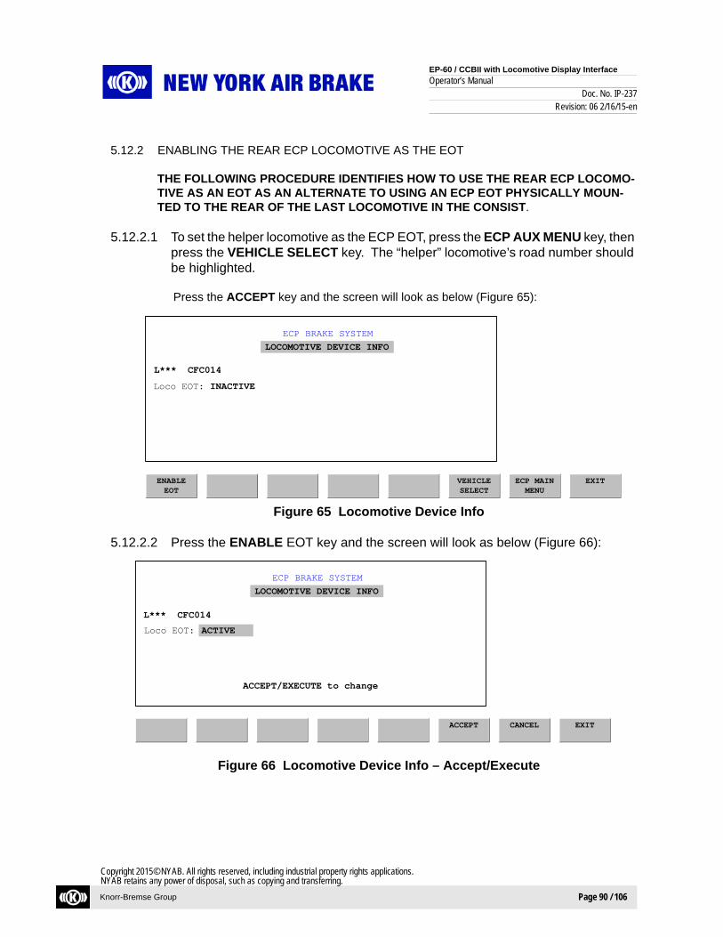
EP-60 / CCBII with Locomotive Display Interface
Operator’s ManualDoc. No. IP-237
Revision: 06 2/16/15-en
Knorr-Bremse Group Page 90 / 106
Copyright 2015© NYAB. All rights reserved, including industrial property rights applications.NYAB retains any power of disposal, such as copying and transferring.
5.12.2 ENABLING THE REAR ECP LOCOMOTIVE AS THE EOT
THE FOLLOWING PROCEDURE IDENTIFIES HOW TO USE THE REAR ECP LOCOMO-TIVE AS AN EOT AS AN ALTERNATE TO USING AN ECP EOT PHYSICALLY MOUN-TED TO THE REAR OF THE LAST LOCOMOTIVE IN THE CONSIST.
5.12.2.1 To set the helper locomotive as the ECP EOT, press the ECP AUX MENU key, then press the VEHICLE SELECT key. The “helper” locomotive’s road number should be highlighted.
Press the ACCEPT key and the screen will look as below (Figure 65):
Figure 65 Locomotive Device Info
5.12.2.2 Press the ENABLE EOT key and the screen will look as below (Figure 66):
Figure 66 Locomotive Device Info – Accept/Execute
ECP BRAKE SYSTEM
ACCEPT CANCEL EXIT
ACCEPT/EXECUTE to change
LOCOMOTIVE DEVICE INFO
Loco EOT:
L*** CFC014
ACTIVE
ECP BRAKE SYSTEM
ENABLEEOT
VEHICLESELECT
ECP MAINMENU
EXIT
LOCOMOTIVE DEVICE INFO
Loco EOT: INACTIVE
L*** CFC014

EP-60 / CCBII with Locomotive Display Interface
Operator’s ManualDoc. No. IP-237
Revision: 06 2/16/15-en
Knorr-Bremse Group Page 91 / 106
Copyright 2015© NYAB. All rights reserved, including industrial property rights applications.NYAB retains any power of disposal, such as copying and transferring.
5.12.2.3 Press the ACCEPT key and the screen will change to (Figure 67):
Figure 67 Locomotive Device Info – EOT Active
This locomotive is now the ECP EOT.
With confirmation from the conductor to the engineer that all the cables and hoses have been connected properly, and he or she is clear from the train, the engineer can initiate the train into RUN mode (see Section 5.1). The “helper” locomotive is now enabled in which the automatic brakes will apply and release in response to the train brake command from the lead ECP locomotive, and is recognized as the EOT.
With the lead locomotive in RUN mode, trainline power established, and all sequencing complete, the engineer can then perform all required brake tests for the helper service.
5.12.3 REMOVING ECP “REMOTE” HELPER SERVICE TO THE TRAIN
The following procedure identifies how to remove an ECP “REMOTE” helper locomotive from the rear of the train.
5.12.3.1 Place the ECP “LEAD” locomotive into “SWITCH” mode (See Section 5.7).
5.12.3.2 With confirmation from the engineer to the conductor that the train is secured, and the trainline power is OFF, the conductor will remove the EOT from the rear of the last locomotive, and install it on the rear of the last car within the consist.
5.12.3.3 With confirmation from the conductor to the engineer that he or she is clear from the train, the “REMOTE” helper locomotive engineer can then break away from the end of the train.
5.12.3.4 Using the AIR BRAKE key on the main menu, place the locomotive as LEAD, CUT IN.
NOTEIf the service in which the train is running does not require an EOT such as loading or dumping, the EOT can be stored elsewhere until it is needed.
ECP BRAKE SYSTEM
DISABLEEOT
VEHICLESELECT
ECP MAINMENU
EXIT
LOCOMOTIVE DEVICE INFO
Loco EOT: ACTIVE
L*** CFC014

EP-60 / CCBII with Locomotive Display Interface
Operator’s ManualDoc. No. IP-237
Revision: 06 2/16/15-en
Knorr-Bremse Group Page 92 / 106
Copyright 2015© NYAB. All rights reserved, including industrial property rights applications.NYAB retains any power of disposal, such as copying and transferring.
5.12.3.5 At that time the locomotive or set of locomotives can be run in either ECP “MODE”, or Conventional “MODE”.
5.12.3.6 To run the locomotive or set of locomotives in ECP “MODE”, the LEAD locomotive must be configured as the ECP LEAD. To place the locomotive in ECP LEAD, press the ECP AUX MENU key, and press the SETUP Key. The screen will look as follows (Figure 68):
Figure 68 Setup
Press the HEU L/T key. The New setting will change to LEAD and a REQUEST CHANGE key will be provided. Press the REQUEST CHANGE key and a prompt “ACCEPT/EXECUTE to change” will be shown.
5.12.3.7 Press the ACCEPT key, the screen will change to (Figure 69):
Figure 69 Setup – Setup Information Saved
5.12.3.8 To run the locomotive or set of locomotives in Conventional ECP “MODE”, see Section 5.6.
ECP BRAKE SYSTEM
SETUP
HEUL/T
ECPMODE
T/LPOWER
ECP AUXMENU
EXIT
<== New<== CurrentTRAIL **** OFF
TRAIL **** OFF
ACCEPT
ECP BRAKE SYSTEM
SETUP
HEUL/T
ECPMODE
T/LPOWER
ECP AUXMENU
EXIT
<== New<== CurrentLEAD ***** OFF
LEAD ***** OFF
ACCEPT
*** Setup information saved ***

EP-60 / CCBII with Locomotive Display Interface
Operator’s ManualDoc. No. IP-237
Revision: 06 2/16/15-en
Knorr-Bremse Group Page 93 / 106
Copyright 2015© NYAB. All rights reserved, including industrial property rights applications.NYAB retains any power of disposal, such as copying and transferring.
5.13 Adding and Removing Cars in an ECP Train
The following procedure identifies the recommended practice of adding and removing freight cars to or from an ECP Train.
5.13.1 ADDING A FREIGHT CAR OR A SET OF FREIGHT CARS TO AN ECP TRAIN
5.13.2 With a locomotive, or locomotive and a set of cars coupled and stretched to the section of cars being added to the train, the engineer will secure the train and ensure that power is “OFF” across the trainline.
With confirmation from the engineer to the conductor that the train is secured, and that trainline power is “OFF”, the conductor can then hook up the air hose and the electrical inter-car connector to the car or set of cars being added to the train. Once connected, the conductor can supply air to the car or set of cars that are being added to the train.
5.13.2.1 With confirmation from the conductor to the engineer that the trainline is clear, the engineer must send power down the trainline to activate the CCD’s. The engineer can now proceed to move the train. At that time the train can either be initialized into ECP “RUN” mode (See Section 5.1), or left in ECP “SWITCH” mode (See Section 5.7).
5.13.3 REMOVING A FREIGHT CAR OR A SET OF FREIGHT CARS FROM AN ECP TRAIN
5.13.3.1 Before removing a car or set of cars from an ECP trainline, the engineer must secure the train, and ensure that the power is “OFF” across the trainline.
With confirmation from the engineer to the conductor that the train is secured, and that trainline power is “OFF”, the conductor can then apply any hand brakes as outlined within that railroad’s guidelines. With the hand brakes applied, the conductor will request from the engineer to release the train, and to perform a C102 test to ensure the hand brakes are set to secure the car or set of cars to be cut from the train.
With the train secure, the engineer will END ECP. After waiting approximately 1 minute, the engineer will confirm to the conductor that the train is secured with T/L Power "OFF". The conductor can then blank the angle cock and disconnect the inter-car connector bet-ween the car or set of cars in which are being cut from the train.
NOTEWhenever adding or removing cars from an ECP train, it is recommended that the train is operated in ECP "SWITCH" Mode.
NOTEWhenever adding or removing cars from an ECP train, it is recommended that the train is operated in ECP "SWITCH" Mode.
EP-60 / CCBII with Locomotive Display Interface
Operator’s ManualDoc. No. IP-237
Revision: 06 2/16/15-en
Knorr-Bremse Group Page 94 / 106
Copyright 2015© NYAB. All rights reserved, including industrial property rights applications.NYAB retains any power of disposal, such as copying and transferring.
5.13.3.2 With confirmation from the conductor to the engineer that the trainline is clear, the engineer will initiate Switch Mode. Once initiated into Switch Mode, the engineer can proceed to move the train ahead to cut out the car or set of cars from the train.
5.14 MANUALLY CUTTING A CAR “OFF” AIR
5.14.1 Manually Cutting A Car Out
5.14.1.1 NYAB recommends manually cutting out all cars within a train that are not communicating to the Head End locomotive, are electronically cut out, or have other mechanical reasons that may attribute to fouled rigging, etc.
5.14.1.2 If deemed necessary to cut a car off air, close the Dirt Collector Cock to that car’s CCD.
5.14.1.3 Vent all stored air from the car’s reservoir by pushing/pulling the manual release rod. To ensure all air is drained from the car’s reservoir, the release rod must be held for 30 seconds or until the sound of air is no longer heard draining from the car, which ever is longer.
5.14.1.4 If two or more cars are manually cut out simultaneously, a low brake pipe emergency will be initiated from the Lead Locomotive due to a Trainline Critical Loss Of Brake Pipe reported by two or more devices on the ECP Trainline network. With the reservoirs completely drained, the Trainline Critical Loss Of Brake Pipe Emergency will clear after timing out.
NOTEIf available, a NYAB TILTD can be placed on the end of the car or cut of cars to allow T/L Power to be energized upon entering Switch mode to conserve CCD battery charge.
NOTEIf the air is not completely drained from a car’s reservoir while attempting to manually cut out, there is potential for a stuck brake situation due to the stored energy remaining in the car’s barke sys-tem.

EP-60 / CCBII with Locomotive Display Interface
Operator’s ManualDoc. No. IP-237
Revision: 06 2/16/15-en
Knorr-Bremse Group Page 95 / 106
Copyright 2015© NYAB. All rights reserved, including industrial property rights applications.NYAB retains any power of disposal, such as copying and transferring.
5.14.2 Manually Cutting a Car In
5.14.2.1 If desired to manually cut a car in, ensure all personnel are clear of the brake rigging for there is potential for the brakes to apply.
5.14.2.2 With the Dirt Collector Cut Out Cock open, there are two ways to cut a car back into the train:
• Using the vehicle select screen within the lead locomotive, select the car to be cut in and use the cut out/cut in function keys as outlined earlier in this document, setting the car to Cut In.
• Re-initializing a train into either Run or Switch Mode.
NOTEIf two or more cars are manually cut out in which the reservoirs have not been completely drained, the ECP system will remain in a Trainline Critical Loss of Brake Pipe Emergency. The only way to clear this Emergency is to completely drain all air from the manually cut out cars, or clear the low brake pipe condition by opening the Dirt Collector Cut Out Cock to the cars cut out (opening the Dirt Col-lector Cut Out Cock may not be desired due to the reasons the car was initially cut out to begin with). With the reservoirs completely drained, the Trainline Critical Loss of Brake Pipe Emergency will clear after timing out.

EP-60 / CCBII with Locomotive Display Interface
Operator’s ManualDoc. No. IP-237
Revision: 06 2/16/15-en
Knorr-Bremse Group Page 96 / 106
Copyright 2015© NYAB. All rights reserved, including industrial property rights applications.NYAB retains any power of disposal, such as copying and transferring.
The following matrix should be used as a quick reference troubleshooting guide.
TROUBLESHOOTING MATRIX:
6 ECP Troubleshooting
Problem Corrective Action/Possible CauseECP Will Not Power Up On Display (OIU, LCDM) Check that ECP Circuit Breaker Is On
Check that the main Locomotive Knife Switch Is “Closed” supplying power to the TCC Breaker.
Check TCC “ON/OFF” Switch is “ON” located In Locomotive Brake Bay
Check the cable connections C7 and C4 at the TCC located in the Brake Bay.
Low BP Pressure If an EOT is present, confirm BP Pressure as reported by the EOT on the Locomotive Display.
Check the Trainline to ensure all Angle Cocks are Open allowing BP to travel the entire length of the train
Confirm that the Locomotive Main Reservoir is Charged.
Check the air flow from the lead locomotive. If found to be excessive, check the system for leaks along the trainline.
Loss Of HEU Comm/No EOT Perform a T/L Comm Test if possible. Correct outstanding issue as determined by T/L Comm Test.
Inspect EOT at the end of the train and verify proper installation.
Disconnect the EOT if present. Initiating Switch Mode, visually inspect the Trainline CCD’s to verify they are on by looking at the CCD’s LEDs. Inspect the Trainline Cable between the cars in which the CCD’s "POWER" LED is off and the CCD’s "POWER" LED is on.
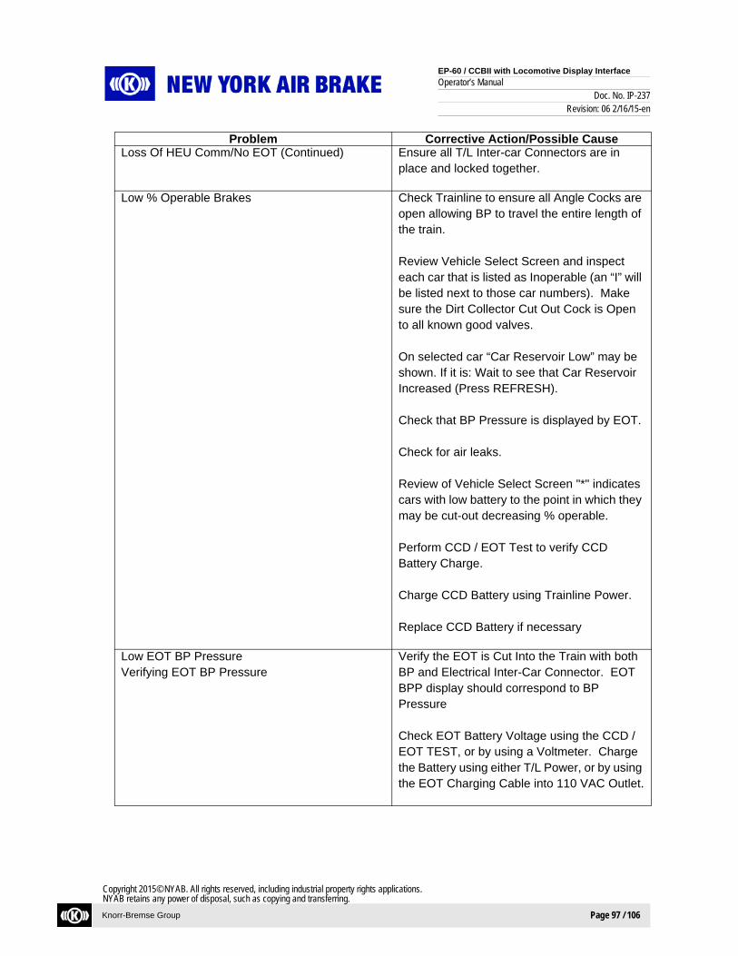
EP-60 / CCBII with Locomotive Display Interface
Operator’s ManualDoc. No. IP-237
Revision: 06 2/16/15-en
Knorr-Bremse Group Page 97 / 106
Copyright 2015© NYAB. All rights reserved, including industrial property rights applications.NYAB retains any power of disposal, such as copying and transferring.
Problem Corrective Action/Possible CauseLoss Of HEU Comm/No EOT (Continued) Ensure all T/L Inter-car Connectors are in
place and locked together.
Low % Operable Brakes Check Trainline to ensure all Angle Cocks are open allowing BP to travel the entire length of the train.
Review Vehicle Select Screen and inspect each car that is listed as Inoperable (an “I” will be listed next to those car numbers). Make sure the Dirt Collector Cut Out Cock is Open to all known good valves.
On selected car “Car Reservoir Low” may be shown. If it is: Wait to see that Car Reservoir Increased (Press REFRESH).
Check that BP Pressure is displayed by EOT.
Check for air leaks.
Review of Vehicle Select Screen "*" indicates cars with low battery to the point in which they may be cut-out decreasing % operable.
Perform CCD / EOT Test to verify CCD Battery Charge. Charge CCD Battery using Trainline Power.
Replace CCD Battery if necessary
Low EOT BP PressureVerifying EOT BP Pressure
Verify the EOT is Cut Into the Train with both BP and Electrical Inter-Car Connector. EOT BPP display should correspond to BP Pressure
Check EOT Battery Voltage using the CCD / EOT TEST, or by using a Voltmeter. Charge the Battery using either T/L Power, or by using the EOT Charging Cable into 110 VAC Outlet.

EP-60 / CCBII with Locomotive Display Interface
Operator’s ManualDoc. No. IP-237
Revision: 06 2/16/15-en
Knorr-Bremse Group Page 98 / 106
Copyright 2015© NYAB. All rights reserved, including industrial property rights applications.NYAB retains any power of disposal, such as copying and transferring.
Problem Corrective Action/Possible CauseLow EOT Battery Charge Check EOT Battery Voltage using a
Voltmeter.
Perform a CCD /EOT Test to verify EOT Battery Charge.
Charge the Battery using either T/L Power, or by using the EOT Charging Cable into 110 VAC Outlet.
Replace EOT batteries if necessary.
Low T/L Power Review T/L Power is on via the Locomotive Display, or the appropriate indicator as found on the Locomotive.
Perform a T/L Power Test to diagnose Supplied T/L Power. Trainline power at the rear of the train (EOT) should be within 50 VDC of the HEU.
If there is a voltage drop of more than 50 VDC across the entire train, there is most likely a poor connection somewhere within the T/L. Using the Vehicle Select Screen, review various vehicles throughout the train. If battery voltage at a specific vehicle reports below 13 VDC continue to look at vehicles towards the front of the train until a vehicle battery voltage >13.0 VDC is reported. A problem exists in the T/L where the cars begin reporting a lower battery voltage then the expected 13.5 VDC.
The problem can also be identified by walking the train and by inspecting the CCD LEDs. The problem exists between the cars in which the Power LEDs show solid red to the next car in which the LED is solid green, indicating that the car is running off of battery power and is not receiving T/L voltage. Check the I/C connectors between these cars.

EP-60 / CCBII with Locomotive Display Interface
Operator’s ManualDoc. No. IP-237
Revision: 06 2/16/15-en
Knorr-Bremse Group Page 99 / 106
Copyright 2015© NYAB. All rights reserved, including industrial property rights applications.NYAB retains any power of disposal, such as copying and transferring.
Problem Corrective Action/Possible Cause
Low T/L Power (continued) If the CCDs have a low battery and are cut out in the train, the Power LED will be off. Activate T/L power from the HEU while simultaneously observing the CCD Power LED. If T/L power reaches the car, the Power LED will "flicker" red then shut down. Check the I/C connector between the cut out cars in which the Power LED "flickers" red and the car in which it does not flicker.
CCD’s Cut Out Low Battery Report Of Incorrect BCP Car ID Fault
Check MAINT LOG for affected car number.
Review VEHICLE SELECT screen for affected car.
Use the VEHICLE SELECT screen to attempt to either cut-in the car or cut-out the car depending on problem; press the MORE key then the cut-in or cut-out key and follow prompts.
Charge battery using T/L Voltage. Replace Battery (Section 5.0). Check Dirt Collector Cut-Out Cock.
Loss Of “HET”: T/L Power Deactivating Check Lead Locomotive Head End Terminal is connected to the Unused Locomotive Inter-car Connector.
T/L Short: “Deactivating T/L Power” Isolate the last locomotive in the Front Consist to Lead Cut In and initiate Run Mode to verify if the T/L problem is within the Leading Locomotives. Continue to isolate each locomotive until the problem locomotive is identified. Once the problem locomotive is identified, use a wrap around cable to bypass the problem locomotive in the T/L.If a T/L short is not found within the locomotive consist, proceed to troubleshoot the remaining trainline to identify the location of the short.

EP-60 / CCBII with Locomotive Display Interface
Operator’s ManualDoc. No. IP-237
Revision: 06 2/16/15-en
Knorr-Bremse Group Page 100 / 106
Copyright 2015© NYAB. All rights reserved, including industrial property rights applications.NYAB retains any power of disposal, such as copying and transferring.
Problem Corrective Action/Possible CauseT/L Short: “Deactivating T/L Power” (continued) Disconnect the Output Connector on all
trailing and remote ECP TPSs. If the problem goes away, one of the Trailing or Remote TPSs are defective.
With the train secure, have the conductor walk the train and disconnect the I/C connector at various places within the train. At each point while operating in Switch Mode press the “Power” key to send power down the T/L. If the section of the train being tested is OK, the Crew Message displayed should say “No EOT Detected T/L Power Shutdown”. If the section of train being tested contains the T/L short, one of two messages may result, “T/L Power Offline” / “No PSCs Detected”. The message “T/L Short” will be present within the Maintenance Logs. Continue moving through the train until the problematic car containing the T/L short is identified.
Using the Vehicle Select Screen, determine if there is a car cut out due to Car ID Fault. This would be the first place to look for a T/L short Identified above.
Once the T/L short is identified in a specific car, a wrap around cable will be required to bypass the problem car. Once the wrap around cable is installed on the problem car, initiate Run Mode.
When to Replace CCD Battery Replace CCD battery as a result of a failed battery test during EPSCTD
Or
Replace CCD battery when a CCD’s “POWER” LED is blinking on/off “Red” and the “FAULT” LED is solid “Red”.
Or
Replace CCD battery when measured voltage across battery reads below 9.5 VDC.

EP-60 / CCBII with Locomotive Display Interface
Operator’s ManualDoc. No. IP-237
Revision: 06 2/16/15-en
Knorr-Bremse Group Page 101 / 106
Copyright 2015© NYAB. All rights reserved, including industrial property rights applications.NYAB retains any power of disposal, such as copying and transferring.
7.1 Inter-Car Connector Pull-Out Repair
7.1.1 Unscrew the connecting nut from the junction box and separate the plastic skid washer from the connecting nut. If not already present, make a cut through the plastic skid washer at a 30 degree angle (see Figure 70).
Figure 70 Cutting the Skid Washer
7.1.2 Slide the connecting nut onto the inter-car cable assembly.
7.1.3 Spread the plastic skid washer just enough to slip it onto the cable assembly between the connecting nut and the connector plug. Position the plastic skid washer so the lip of the skid washer is against the lip of the connector plug (see Figure 71).
Figure 71 Installing the Skid Washer
7 Inter-Car Connector Pull-Out Repair

EP-60 / CCBII with Locomotive Display Interface
Operator’s ManualDoc. No. IP-237
Revision: 06 2/16/15-en
Knorr-Bremse Group Page 102 / 106
Copyright 2015© NYAB. All rights reserved, including industrial property rights applications.NYAB retains any power of disposal, such as copying and transferring.
7.1.4 Slide the connecting nut forward over the plastic skid washer and the connector.
7.1.5 Ensure the o-ring is properly installed on the connecting nut as illustrated in Figure 72.
Figure 72 Correct O-Ring Installation
7.1.6 Plug the inter-car cable assembly into the EOC and carefully thread the nut of the inter-car cable assembly into the female threads of the EOC assembly.
7.1.7 The hex nut should be hand tightened to junction box until tight. Then, using a 2-1/4” open end or adjustable wrench, tighten an additional 1/3 turn. Ensure that the o-ring is not exposed outside of the hex nut after tightening the hex nut.
NOTEUse caution when threading the cable assembly into the EOC to avoid cross threading.

EP-60 / CCBII with Locomotive Display Interface
Operator’s ManualDoc. No. IP-237
Revision: 06 2/16/15-en
Knorr-Bremse Group Page 103 / 106
Copyright 2015© NYAB. All rights reserved, including industrial property rights applications.NYAB retains any power of disposal, such as copying and transferring.
8.1 Replacement Procedure: Inter-Car Connector Lanyard
Figure 73 Lanyard Strap Assembly Replacement Kits
8.1.1 Remove the Inter-Car Connector Cable Assembly by unscrewing the gland nut from the junction box and separating the plastic skid washer from the gland nut (Figure 74).
Figure 74 Removing the Inter-Car Connector Cable Assembly
8 Inter-Car Connector Lanyard Replacement

EP-60 / CCBII with Locomotive Display Interface
Operator’s ManualDoc. No. IP-237
Revision: 06 2/16/15-en
Knorr-Bremse Group Page 104 / 106
Copyright 2015© NYAB. All rights reserved, including industrial property rights applications.NYAB retains any power of disposal, such as copying and transferring.
8.1.2 If not already present, make a cut through the plastic skid washer at a 30 degree angle and remove from the Inter-Car Connector Cable Assebly. Then pull the glad nut off the inter-car connector plug.
8.1.3 Using a special thin walled deep well 3/8" hex socket, remove the eyebolt nut located in the recessed hole within the Inter-Car Connector boot (see Figure 75).
Figure 75 Remove Eyebolt Nut
8.1.4 With the gland nut removed, slide the damaged lanyard off the Inter-Car Connector Cable Assembly as shown in Figure 72 and replace with the new lanyard from the Lanyard Strap Assembly Replacement Kit as shown in Figure 76.
Figure 76 Remove Damaged Lanyard

EP-60 / CCBII with Locomotive Display Interface
Operator’s ManualDoc. No. IP-237
Revision: 06 2/16/15-en
Knorr-Bremse Group Page 105 / 106
Copyright 2015© NYAB. All rights reserved, including industrial property rights applications.NYAB retains any power of disposal, such as copying and transferring.
Figure 77 Install New Lanyard
8.1.5 Apply Loctite Grade 271 to the threads of the lanyard eyebolt. Using the lock nut and washer supplied with the Lanyard Replacement Kit, reconnect the lanyard eyebolt to the Inter-Car Connector boot using a torque value of 150 in-lbs (see Figure 78).
Figure 78 Reconnect the Lanyard Eyebolt

EP-60 / CCBII with Locomotive Display Interface
Operator’s ManualDoc. No. IP-237
Revision: 06 2/16/15-en
Knorr-Bremse Group Page 106 / 106
Copyright 2015© NYAB. All rights reserved, including industrial property rights applications.NYAB retains any power of disposal, such as copying and transferring.
For Further Technical AssistanceContact Our
24 Hour Help Desk
at
1-800-645-4564