ip multicast: pim configuration guide, cisco ios release 12 · protocol independent multicast 8 pim...
TRANSCRIPT

IP Multicast: PIM Configuration Guide,Cisco IOS Release 12.4T
Americas HeadquartersCisco Systems, Inc.170 West Tasman DriveSan Jose, CA 95134-1706USAhttp://www.cisco.comTel: 408 526-4000 800 553-NETS (6387)Fax: 408 527-0883

THE SPECIFICATIONS AND INFORMATION REGARDING THE PRODUCTS IN THIS MANUAL ARE SUBJECT TO CHANGE WITHOUT NOTICE. ALL STATEMENTS,INFORMATION, AND RECOMMENDATIONS IN THIS MANUAL ARE BELIEVED TO BE ACCURATE BUT ARE PRESENTED WITHOUT WARRANTY OF ANY KIND,EXPRESS OR IMPLIED. USERS MUST TAKE FULL RESPONSIBILITY FOR THEIR APPLICATION OF ANY PRODUCTS.
THE SOFTWARE LICENSE AND LIMITED WARRANTY FOR THE ACCOMPANYING PRODUCT ARE SET FORTH IN THE INFORMATION PACKET THAT SHIPPEDWITH THE PRODUCT AND ARE INCORPORATED HEREIN BY THIS REFERENCE. IF YOU ARE UNABLE TO LOCATE THE SOFTWARE LICENSE OR LIMITEDWARRANTY, CONTACT YOUR CISCO REPRESENTATIVE FOR A COPY.
The Cisco implementation of TCP header compression is an adaptation of a program developed by the University of California, Berkeley (UCB) as part of UCB’s public domain versionof the UNIX operating system. All rights reserved. Copyright © 1981, Regents of the University of California.
NOTWITHSTANDING ANY OTHER WARRANTY HEREIN, ALL DOCUMENT FILES AND SOFTWARE OF THESE SUPPLIERS ARE PROVIDED “AS IS” WITH ALLFAULTS. CISCO AND THE ABOVE-NAMED SUPPLIERS DISCLAIM ALL WARRANTIES, EXPRESSED OR IMPLIED, INCLUDING, WITHOUT LIMITATION, THOSE OFMERCHANTABILITY, FITNESS FOR A PARTICULAR PURPOSE AND NONINFRINGEMENT OR ARISING FROM A COURSE OF DEALING, USAGE, OR TRADEPRACTICE.
IN NO EVENT SHALL CISCO OR ITS SUPPLIERS BE LIABLE FOR ANY INDIRECT, SPECIAL, CONSEQUENTIAL, OR INCIDENTAL DAMAGES, INCLUDING,WITHOUT LIMITATION, LOST PROFITS OR LOSS OR DAMAGE TO DATA ARISING OUT OF THE USE OR INABILITY TO USE THIS MANUAL, EVEN IF CISCO ORITS SUPPLIERS HAVE BEEN ADVISED OF THE POSSIBILITY OF SUCH DAMAGES.
Cisco and the Cisco logo are trademarks or registered trademarks of Cisco and/or its affiliates in the U.S. and other countries. To view a list of Cisco trademarks, go to this URL: www.cisco.com/go/trademarks. Third-party trademarks mentioned are the property of their respective owners. The use of the word partner does not imply a partnership relationshipbetween Cisco and any other company. (1110R)
Any Internet Protocol (IP) addresses and phone numbers used in this document are not intended to be actual addresses and phone numbers. Any examples, command display output,network topology diagrams, and other figures included in the document are shown for illustrative purposes only. Any use of actual IP addresses or phone numbers in illustrative contentis unintentional and coincidental.
© 2012 Cisco Systems, Inc. All rights reserved.
C O N T E N T S
IP Multicast Technology Overview 1
Finding Feature Information 1
Information About IP Multicast Technology 1
Role of IP Multicast in Information Delivery 2
Multicast Group Transmission Scheme 2
IP Multicast Routing Protocols 4
IP Multicast Group Addressing 5
IP Class D Addresses 5
IP Multicast Address Scoping 5
Layer 2 Multicast Addresses 7
IP Multicast Delivery Modes 7
Any Source Multicast 7
Source Specific Multicast 7
Protocol Independent Multicast 8
PIM Dense Mode 8
PIM Sparse Mode 9
Sparse-Dense Mode 9
Bidirectional PIM 10
Multicast Group Modes 10
Bidirectional Mode 11
Sparse Mode 11
Dense Mode 11
Rendezvous Points 11
Auto-RP 12
Sparse-Dense Mode for Auto-RP 13
Bootstrap Router 13
Multicast Source Discovery Protocol 13
Anycast RP 14
Multicast Forwarding 14
IP Multicast: PIM Configuration Guide, Cisco IOS Release 12.4T iii

Multicast Distribution Source Tree 15
Multicast Distribution Shared Tree 16
Source Tree Advantage 16
Shared Tree Advantage 17
Reverse Path Forwarding 17
RPF Check 17
PIM Dense Mode Fallback 18
Guidelines for Choosing a PIM Mode 19
Where to Go Next 20
Additional References 20
Feature Information for IP Multicast Technology Overview 21
Glossary 21
Configuring Basic IP Multicast 25
Finding Feature Information 25
Prerequisites for Configuring Basic IP Multicast 25
Information About Configuring Basic IP Multicast 26
Auto-RP Overview 26
The Role of Auto-RP in a PIM Network 26
IP Multicast Boundary 26
Benefits of Auto-RP in a PIM Network 27
Anycast RP Overview 27
BSR Overview 28
BSR Election and Functionality 28
BSR Border Interface 28
Static RP Overview 28
SSM Overview 29
SSM Components 29
How SSM Differs from Internet Standard Multicast 29
SSM Operations 30
IGMPv3 Host Signaling 30
Benefits of Source Specific Multicast 31
Bidir-PIM Overview 32
Multicast Group Modes 32
Bidirectional Shared Tree 32
DF Election 34
Contents
IP Multicast: PIM Configuration Guide, Cisco IOS Release 12.4Tiv

Bidirectional Group Tree Building 34
Packet Forwarding 34
Benefits of Bidirectional PIM 35
How to Configure Basic IP Multicast 35
Configuring Sparse Mode with Auto-RP 35
What to Do Next 40
Configuring Sparse Mode with Anycast RP 40
What to Do Next 44
Configuring Sparse Mode with a Bootstrap Router 44
What to Do Next 49
Configuring Sparse Mode with a Single Static RP 49
What to Do Next 51
Configuring Source Specific Multicast 52
What to Do Next 54
Configuring Bidirectional PIM 54
Configuration Examples for Basic IP Multicast 56
Sparse Mode with Auto-RP Example 57
Sparse Mode with Anycast RP Example 57
Sparse Mode with Bootstrap Router Example 59
BSR and RFC 2362 Interoperable Candidate RP Example 59
Sparse Mode with a Single Static RP Example 60
SSM with IGMPv3 Example 60
SSM Filtering Example 61
Bidir-PIM Example 61
Additional References 62
Feature Information for Configuring Basic IP Multicast 63
Using MSDP to Interconnect Multiple PIM-SM Domains 65
Finding Feature Information 65
Prerequisites for Using MSDP to Interconnect Multiple PIM-SM Domains 65
Information About Using MSDP to Interconnect Multiple PIM-SM Domains 66
Benefits of Using MSDP to Interconnect Multiple PIM-SM Domains 66
Use of MSDP to Interconnect Multiple PIM-SM Domains 66
MSDP Message Types 69
SA Messages 69
SA Request Messages 69
Contents
IP Multicast: PIM Configuration Guide, Cisco IOS Release 12.4T v
SA Response Messages 69
Keepalive Messages 70
SA Message Origination Receipt and Processing 70
SA Message Origination 70
SA Message Receipt 70
How RPF Check Rules Are Applied to SA Messages 71
How the Software Determines the Rule to Apply to RPF Checks 71
Rule 1 of RPF Checking of SA Messages in MSDP 71
Implications of Rule 1 of RPF Checking on MSDP 72
Rule 2 of RPF Checking of SA Messages in MSDP 72
Implications of Rule 2 of RPF Checking on MSDP 72
Rule 3 of RPF Checking of SA Messages in MSDP 73
SA Message Processing 73
MSDP Peers 73
MSDP MD5 Password Authentication 74
How MSDP MD5 Password Authentication Works 74
Benefits of MSDP MD5 Password Authentication 74
SA Message Limits 74
MSDP Keepalive and Hold-Time Intervals 74
MSDP Connection-Retry Interval 75
MSDP Compliance with IETF RFC 3618 75
Benefits of MSDP Compliance with RFC 3618 75
Default MSDP Peers 76
MSDP Mesh Groups 77
Benefits of MSDP Mesh Groups 77
SA Origination Filters 78
Use of Outgoing Filter Lists in MSDP 79
Use of Incoming Filter Lists in MSDP 80
TTL Thresholds in MSDP 81
SA Request Messages 81
SA Request Filters 81
MSDP MIB 82
How to Use MSDP to Interconnect Multiple PIM-SM Domains 82
Configuring an MSDP Peer 83
Shutting Down an MSDP Peer 84
Contents
IP Multicast: PIM Configuration Guide, Cisco IOS Release 12.4Tvi
Configuring MSDP MD5 Password Authentication Between MSDP Peers 85
Troubleshooting Tips 86
Preventing DoS Attacks by Limiting the Number of SA Messages Allowed in the SA Cache
from Specified MSDP Peers 87
Adjusting the MSDP Keepalive and Hold-Time Intervals 88
Adjusting the MSDP Connection-Retry Interval 90
Configuring MSDP Compliance with IETF RFC 3618 91
Configuring a Default MSDP Peer 92
Configuring an MSDP Mesh Group 93
Controlling SA Messages Originated by an RP for Local Sources 94
Controlling the Forwarding of SA Messages to MSDP Peers Using Outgoing Filter Lists 95
Controlling the Receipt of SA Messages from MSDP Peers Using Incoming Filter Lists 96
Using TTL Thresholds to Limit the Multicast Data Sent in SA Messages 97
Requesting Source Information from MSDP Peers 98
Controlling the Response to Outgoing SA Request Messages from MSDP Peers Using SA
Request Filters 100
Including a Bordering PIM Dense Mode Region in MSDP 101
Configuring an Originating Address Other Than the RP Address 102
Monitoring MSDP 103
Clearing MSDP Connections Statistics and SA Cache Entries 105
Enabling SNMP Monitoring of MSDP 106
Troubleshooting Tips 107
Configuration Examples for Using MSDP to Interconnect Multiple PIM-SM Domains 108
Configuring an MSDP Peer Example 108
Configuring MSDP MD5 Password Authentication Example 108
Configuring MSDP Compliance with IETF RFC 3618 Example 109
Configuring a Default MSDP Peer Example 109
Configuring MSDP Mesh Groups Example 110
Additional References 110
Feature Information for Using MSDP to Interconnect Multiple PIM-SM Domains 112
Configuring Source Specific Multicast 115
Finding Feature Information 115
Restrictions for Source Specific Multicast 115
Information About Source Specific Multicast 117
SSM Overview 117
Contents
IP Multicast: PIM Configuration Guide, Cisco IOS Release 12.4T vii

SSM Components 117
How SSM Differs from Internet Standard Multicast 117
SSM Operations 118
IGMPv3 Host Signaling 119
Benefits of Source Specific Multicast 119
IGMP v3lite Host Signalling 120
URD Host Signalling 121
How to Configure Source Specific Multicast 122
Configuring SSM 123
Monitoring SSM 124
Configuration Examples of Source Specific Multicast 124
SSM with IGMPv3 Example 125
SSM with IGMP v3lite and URD Example 125
SSM Filtering Example 125
Additional References 126
Implementing Multicast Stub Routing 129
Finding Feature Information 129
Prerequisites for Multicast Stub Routing 129
Restrictions for Multicast Stub Routing 130
Information About Multicast Stub Routing 130
Multicast Stub Networks 130
Multicast Stub Routing 130
Multicast Stub Routing Between Stub and Distribution Routers 131
Multicast Stub Routing Between the Stub Router and Interested Receivers 131
Benefits of Multicast Stub Routing 131
How to Implement Multicast Stub Routing 131
Implementing Multicast Stub Routing 131
Prerequisites 132
Restrictions 132
Configuring the Stub Router for Multicast Stub Routing 132
Configuring the Distribution Router for Multicast Stub Routing 135
Configuration Examples for Implementing Multicast Stub Routing 137
Examples Implementing Multicast Stub Routing 137
Example Implementing Multicast Stub Routing - PIM-DM 137
Example Implementing Multicast Stub Routing - PIM-SM Static RP 138
Contents
IP Multicast: PIM Configuration Guide, Cisco IOS Release 12.4Tviii

Example Implementing Multicast Stub Routing - PIM-SSM 139
Example Implementing Multicast Stub Routing - Bidir-PIM 140
Additional References 141
Feature Information for Implementing Multicast Stub Routing 142
Tunneling to Connect Non-IP Multicast Areas 145
Finding Feature Information 145
Prerequisites for Tunneling to Connect Non-IP Multicast Areas 145
Information About Tunneling to Connect Non-IP Multicast Areas 145
Benefits of Tunneling to Connect Non-IP Multicast Areas 146
IP Multicast Static Route 146
How to Connect Non-IP Multicast Areas 146
Configuring a Tunnel to Connect Non-IP Multicast Areas 147
Configuration Examples for Tunneling to Connect Non-IP Multicast Areas 150
Tunneling to Connect Non-IP Multicast Areas Example 150
Additional References 152
Feature Information for Tunneling to Connect Non-IP Multicast Areas 153
Verifying IP Multicast Operation 155
Finding Feature Information 155
Prerequisites for Verifying IP Multicast Operation 155
Restrictions for Verifying IP Multicast Operation 155
Information About Verifying IP Multicast Operation 156
Guidelines for Verifying IP Multicast Operation in a PIM-SM and PIM-SSM Network
Environment 156
Common Commands Used to Verify IP Multicast Operation on the Last Hop Router for
PIM-SM and PIM-SSM 156
Common Commands Used to Verify IP Multicast Operation on Routers Along the SPT for
PIM-SM and PIM-SSM 158
Common Commands Used to Verify IP Multicast Operation on the First Hop Router for
PIM-SM and PIM-SSM 158
How to Verify IP Multicast Operation 159
Using PIM-Enabled Routers to Test IP Multicast Reachability 159
Configuring Routers to Respond to Multicast Pings 159
Pinging Routers Configured to Respond to Multicast Pings 160
Verifying IP Multicast Operation in a PIM-SM or a PIM-SSM Network 161
Verifying IP Multicast Operation on the Last Hop Router 161
Verifying IP Multicast on Routers Along the SPT 165
Contents
IP Multicast: PIM Configuration Guide, Cisco IOS Release 12.4T ix
Verifying IP Multicast on the First Hop Router 166
Configuration Examples for Verifying IP Multicast Operation 167
Verifying IP Multicast Operation in a PIM-SM or PIM-SSM Network Example 168
Verifying IP Multicast on the Last Hop Router Example 168
Verifying IP Multicast on Routers Along the SPT Example 171
Verifying IP Multicast on the First Hop Router Example 171
Additional References 172
Feature Information for Verifying IP Multicast Operation 173
SNMP Traps for IP Multicast 175
Finding Feature Information 175
Prerequisites for SNMP Traps for IP Multicast 175
Restrictions for SNMP Traps for IP Multicast 175
Information About SNMP Traps for IP Multicast 176
PIM MIB Extensions for SNMP Traps for IP Multicast 176
Benefits of PIM MIB Extensions 176
How to Configure SNMP Traps for IP Multicast 176
Enabling PIM MIB Extensions for IP Multicast 177
Configuration Examples for SNMP Traps for IP Multicast 178
Example Enabling PIM MIB Extensions for IP Multicast 178
Additional References 178
Feature Information for SNMP Traps for IP Multicast 179
Monitoring and Maintaining IP Multicast 181
Finding Feature Information 181
Prerequisites for Monitoring and Maintaining IP Multicast 181
Information About Monitoring and Maintaining IP Multicast 182
IP Multicast Delivery Using IP Multicast Heartbeat 182
IP Multicast Heartbeat 182
SNMP Notifications 182
Session Announcement Protocol (SAP) 183
How to Monitor and Maintain IP Multicast 183
Displaying Multicast Peers Packet Rates and Loss Information and Tracing a Path 184
Displaying IP Multicast System and Network Statistics 185
Clearing IP Multicast Routing Table or Caches 186
Monitoring IP Multicast Delivery Using IP Multicast Heartbeat 188
Advertising Multicast Multimedia Sessions Using SAP Listener 189
Contents
IP Multicast: PIM Configuration Guide, Cisco IOS Release 12.4Tx

Storing IP Multicast Headers 191
Disabling Fast Switching of IP Multicast 192
Configuration Examples for Monitoring and Maintaining IP Multicast 193
Example Displaying Multicast Peers Packet Rates and Loss Information and Tracing a Path 193
Example Displaying IP Multicast System and Network Statistics 194
Example Monitoring IP Multicast Delivery Using IP Multicast Heartbeat 196
Example Advertising Multicast Multimedia Sessions Using SAP Listener 197
Example Storing IP Multicast Headers 197
Additional References 197
Contents
IP Multicast: PIM Configuration Guide, Cisco IOS Release 12.4T xi

Contents
IP Multicast: PIM Configuration Guide, Cisco IOS Release 12.4Txii
IP Multicast Technology Overview
IP multicast is a bandwidth-conserving technology that reduces traffic by delivering a single stream ofinformation simultaneously to potentially thousands of businesses and homes. Applications that takeadvantage of multicast include video conferencing, corporate communications, distance learning, anddistribution of software, stock quotes, and news.
This module contains a technical overview of IP multicast. IP multicast is an efficient way to use networkresources, especially for bandwidth-intensive services such as audio and video. Before beginning toconfigure IP multicast, it is important that you understand the information presented in this module.
• Finding Feature Information, page 1• Information About IP Multicast Technology, page 1• Where to Go Next, page 20• Additional References, page 20• Feature Information for IP Multicast Technology Overview, page 21• Glossary, page 21
Finding Feature InformationYour software release may not support all the features documented in this module. For the latest featureinformation and caveats, see the release notes for your platform and software release. To find informationabout the features documented in this module, and to see a list of the releases in which each feature issupported, see the Feature Information Table at the end of this document.
Use Cisco Feature Navigator to find information about platform support and Cisco software image support.To access Cisco Feature Navigator, go to www.cisco.com/go/cfn. An account on Cisco.com is not required.
Information About IP Multicast Technology• Role of IP Multicast in Information Delivery, page 2• Multicast Group Transmission Scheme, page 2• IP Multicast Routing Protocols, page 4• IP Multicast Group Addressing, page 5• IP Multicast Address Scoping, page 5• Layer 2 Multicast Addresses, page 7• IP Multicast Delivery Modes, page 7• Protocol Independent Multicast, page 8• Multicast Group Modes, page 10
IP Multicast: PIM Configuration Guide, Cisco IOS Release 12.4T 1
• Rendezvous Points, page 11
• Multicast Forwarding, page 14
• PIM Dense Mode Fallback, page 18
• Guidelines for Choosing a PIM Mode, page 19
Role of IP Multicast in Information DeliveryIP multicast is a bandwidth-conserving technology that reduces traffic by delivering a single stream ofinformation simultaneously to potentially thousands of businesses and homes. Applications that takeadvantage of multicast include video conferencing, corporate communications, distance learning, anddistribution of software, stock quotes, and news.
IP multicast routing enables a host (source) to send packets to a group of hosts (receivers) anywhere withinthe IP network by using a special form of IP address called the IP multicast group address. The sendinghost inserts the multicast group address into the IP destination address field of the packet and IP multicastrouters and multilayer switches forward incoming IP multicast packets out all interfaces that lead to themembers of the multicast group. Any host, regardless of whether it is a member of a group, can send to agroup. However, only the members of a group receive the message.
Multicast Group Transmission SchemeIP communication consists of hosts that act as senders and receivers of traffic as shown in the first figure.Senders are called sources. Traditional IP communication is accomplished by a single host source sendingpackets to another single host (unicast transmission) or to all hosts (broadcast transmission). IP multicastprovides a third scheme, allowing a host to send packets to a subset of all hosts (multicast transmission).This subset of receiving hosts is called a multicast group. The hosts that belong to a multicast group arecalled group members.
Multicast is based on this group concept. A multicast group is an arbitrary number of receivers that join agroup in order to receive a particular data stream. This multicast group has no physical or geographicalboundaries--the hosts can be located anywhere on the Internet or on any private internetwork. Hosts that areinterested in receiving data from a source to a particular group must join that group. Joining a group isaccomplished by a host receiver by way of the Internet Group Management Protocol (IGMP).
In a multicast environment, any host, regardless of whether it is a member of a group, can send to a group.However, only the members of a group can receive packets sent to that group. Multicast packets aredelivered to a group using best-effort reliability, just like IP unicast packets.
Role of IP Multicast in Information Delivery Information About IP Multicast Technology
IP Multicast: PIM Configuration Guide, Cisco IOS Release 12.4T2
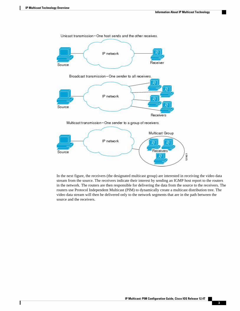
In the next figure, the receivers (the designated multicast group) are interested in receiving the video datastream from the source. The receivers indicate their interest by sending an IGMP host report to the routersin the network. The routers are then responsible for delivering the data from the source to the receivers. Therouters use Protocol Independent Multicast (PIM) to dynamically create a multicast distribution tree. Thevideo data stream will then be delivered only to the network segments that are in the path between thesource and the receivers.
IP Multicast Technology OverviewInformation About IP Multicast Technology
IP Multicast: PIM Configuration Guide, Cisco IOS Release 12.4T 3
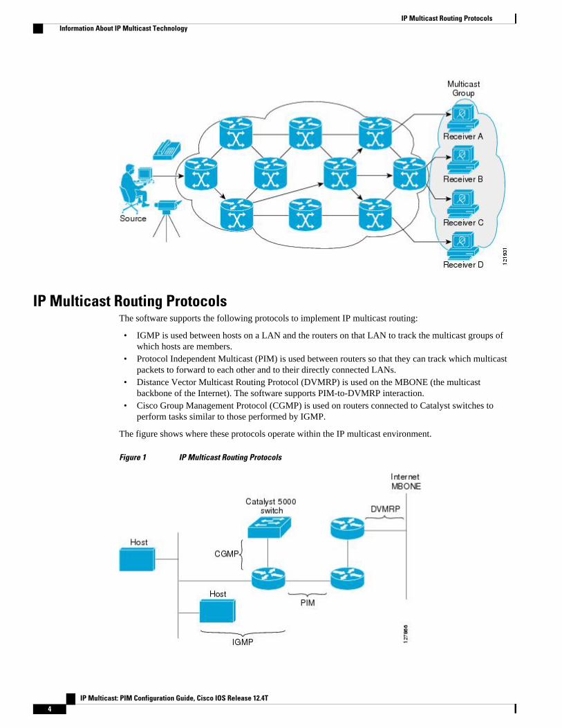
IP Multicast Routing ProtocolsThe software supports the following protocols to implement IP multicast routing:
• IGMP is used between hosts on a LAN and the routers on that LAN to track the multicast groups ofwhich hosts are members.
• Protocol Independent Multicast (PIM) is used between routers so that they can track which multicastpackets to forward to each other and to their directly connected LANs.
• Distance Vector Multicast Routing Protocol (DVMRP) is used on the MBONE (the multicastbackbone of the Internet). The software supports PIM-to-DVMRP interaction.
• Cisco Group Management Protocol (CGMP) is used on routers connected to Catalyst switches toperform tasks similar to those performed by IGMP.
The figure shows where these protocols operate within the IP multicast environment.
Figure 1 IP Multicast Routing Protocols
IP Multicast Routing Protocols Information About IP Multicast Technology
IP Multicast: PIM Configuration Guide, Cisco IOS Release 12.4T4
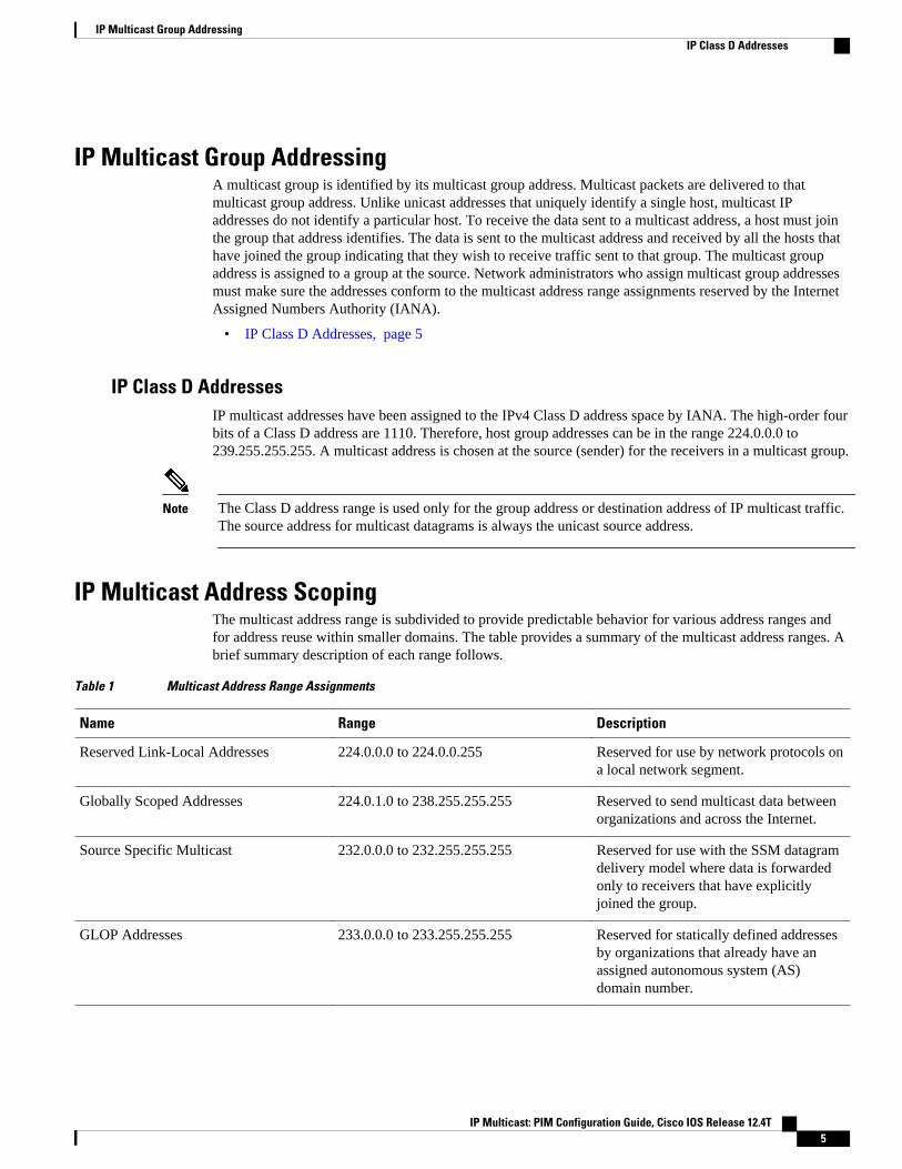
IP Multicast Group AddressingA multicast group is identified by its multicast group address. Multicast packets are delivered to thatmulticast group address. Unlike unicast addresses that uniquely identify a single host, multicast IPaddresses do not identify a particular host. To receive the data sent to a multicast address, a host must jointhe group that address identifies. The data is sent to the multicast address and received by all the hosts thathave joined the group indicating that they wish to receive traffic sent to that group. The multicast groupaddress is assigned to a group at the source. Network administrators who assign multicast group addressesmust make sure the addresses conform to the multicast address range assignments reserved by the InternetAssigned Numbers Authority (IANA).
• IP Class D Addresses, page 5
IP Class D AddressesIP multicast addresses have been assigned to the IPv4 Class D address space by IANA. The high-order fourbits of a Class D address are 1110. Therefore, host group addresses can be in the range 224.0.0.0 to239.255.255.255. A multicast address is chosen at the source (sender) for the receivers in a multicast group.
Note The Class D address range is used only for the group address or destination address of IP multicast traffic.The source address for multicast datagrams is always the unicast source address.
IP Multicast Address ScopingThe multicast address range is subdivided to provide predictable behavior for various address ranges andfor address reuse within smaller domains. The table provides a summary of the multicast address ranges. Abrief summary description of each range follows.
Table 1 Multicast Address Range Assignments
Name Range Description
Reserved Link-Local Addresses 224.0.0.0 to 224.0.0.255 Reserved for use by network protocols ona local network segment.
Globally Scoped Addresses 224.0.1.0 to 238.255.255.255 Reserved to send multicast data betweenorganizations and across the Internet.
Source Specific Multicast 232.0.0.0 to 232.255.255.255 Reserved for use with the SSM datagramdelivery model where data is forwardedonly to receivers that have explicitlyjoined the group.
GLOP Addresses 233.0.0.0 to 233.255.255.255 Reserved for statically defined addressesby organizations that already have anassigned autonomous system (AS)domain number.
IP Multicast Group AddressingIP Class D Addresses
IP Multicast: PIM Configuration Guide, Cisco IOS Release 12.4T 5
Name Range Description
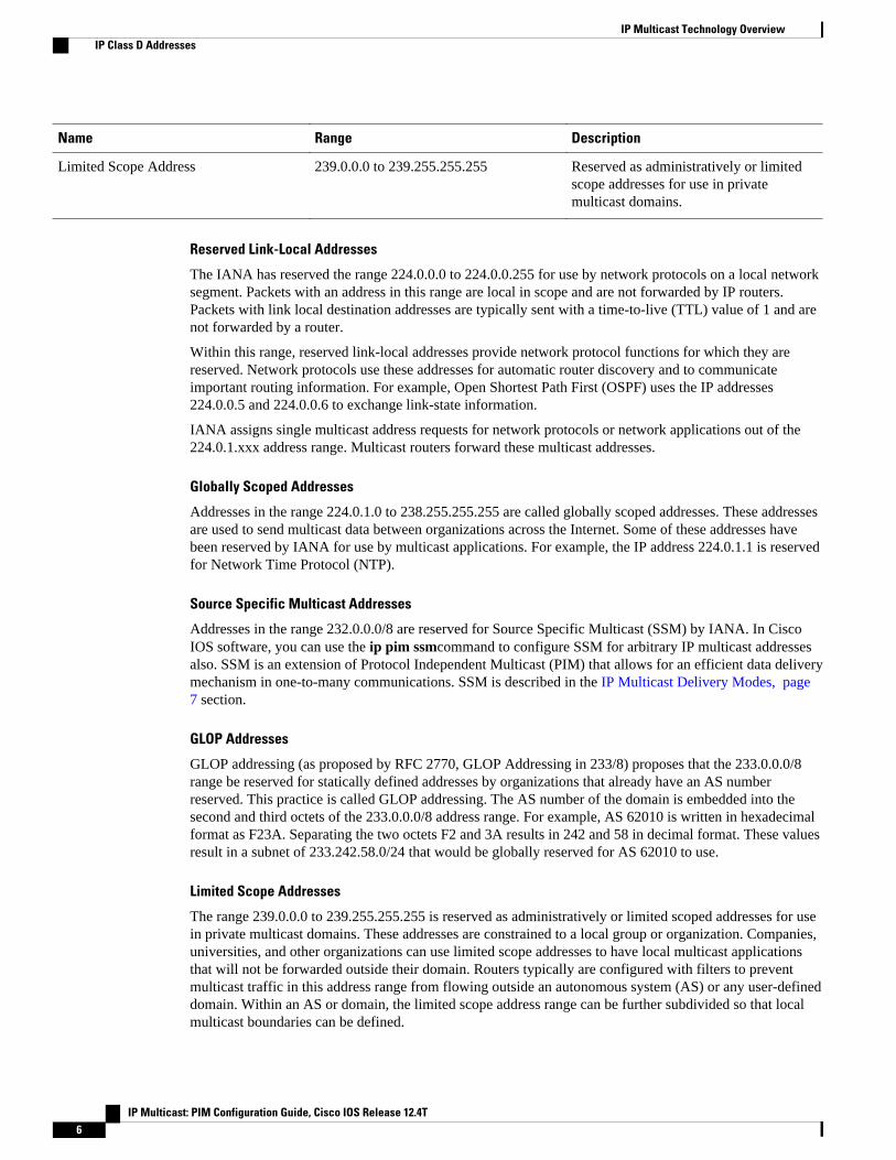
Limited Scope Address 239.0.0.0 to 239.255.255.255 Reserved as administratively or limitedscope addresses for use in privatemulticast domains.
Reserved Link-Local Addresses
The IANA has reserved the range 224.0.0.0 to 224.0.0.255 for use by network protocols on a local networksegment. Packets with an address in this range are local in scope and are not forwarded by IP routers.Packets with link local destination addresses are typically sent with a time-to-live (TTL) value of 1 and arenot forwarded by a router.
Within this range, reserved link-local addresses provide network protocol functions for which they arereserved. Network protocols use these addresses for automatic router discovery and to communicateimportant routing information. For example, Open Shortest Path First (OSPF) uses the IP addresses224.0.0.5 and 224.0.0.6 to exchange link-state information.
IANA assigns single multicast address requests for network protocols or network applications out of the224.0.1.xxx address range. Multicast routers forward these multicast addresses.
Globally Scoped Addresses
Addresses in the range 224.0.1.0 to 238.255.255.255 are called globally scoped addresses. These addressesare used to send multicast data between organizations across the Internet. Some of these addresses havebeen reserved by IANA for use by multicast applications. For example, the IP address 224.0.1.1 is reservedfor Network Time Protocol (NTP).
Source Specific Multicast Addresses
Addresses in the range 232.0.0.0/8 are reserved for Source Specific Multicast (SSM) by IANA. In CiscoIOS software, you can use the ip pim ssmcommand to configure SSM for arbitrary IP multicast addressesalso. SSM is an extension of Protocol Independent Multicast (PIM) that allows for an efficient data deliverymechanism in one-to-many communications. SSM is described in the IP Multicast Delivery Modes, page7 section.
GLOP Addresses
GLOP addressing (as proposed by RFC 2770, GLOP Addressing in 233/8) proposes that the 233.0.0.0/8range be reserved for statically defined addresses by organizations that already have an AS numberreserved. This practice is called GLOP addressing. The AS number of the domain is embedded into thesecond and third octets of the 233.0.0.0/8 address range. For example, AS 62010 is written in hexadecimalformat as F23A. Separating the two octets F2 and 3A results in 242 and 58 in decimal format. These valuesresult in a subnet of 233.242.58.0/24 that would be globally reserved for AS 62010 to use.
Limited Scope Addresses
The range 239.0.0.0 to 239.255.255.255 is reserved as administratively or limited scoped addresses for usein private multicast domains. These addresses are constrained to a local group or organization. Companies,universities, and other organizations can use limited scope addresses to have local multicast applicationsthat will not be forwarded outside their domain. Routers typically are configured with filters to preventmulticast traffic in this address range from flowing outside an autonomous system (AS) or any user-defineddomain. Within an AS or domain, the limited scope address range can be further subdivided so that localmulticast boundaries can be defined.
IP Multicast Technology Overview IP Class D Addresses
IP Multicast: PIM Configuration Guide, Cisco IOS Release 12.4T6
Note Network administrators may use multicast addresses in this range, inside a domain, without conflictingwith others elsewhere in the Internet.
Layer 2 Multicast AddressesHistorically, network interface cards (NICs) on a LAN segment could receive only packets destined fortheir burned-in MAC address or the broadcast MAC address. In IP multicast, several hosts need to be ableto receive a single data stream with a common destination MAC address. Some means had to be devised sothat multiple hosts could receive the same packet and still be able to differentiate between several multicastgroups. One method to accomplish this is to map IP multicast Class D addresses directly to a MAC address.Using this method, NICs can receive packets destined to many different MAC address.
Cisco Group Management Protocol ( CGMP) is used on routers connected to Catalyst switches to performtasks similar to those performed by IGMP. CGMP is necessary for those Catalyst switches that cannotdistinguish between IP multicast data packets and IGMP report messages, both of which are addressed tothe same group address at the MAC level.
IP Multicast Delivery ModesIP multicast delivery modes differ only for the receiver hosts, not for the source hosts. A source host sendsIP multicast packets with its own IP address as the IP source address of the packet and a group address asthe IP destination address of the packet.
• Any Source Multicast, page 7• Source Specific Multicast, page 7
Any Source MulticastFor the Any Source Multicast (ASM) delivery mode, an IP multicast receiver host can use any version ofIGMP to join a multicast group. This group is notated as G in the routing table state notation. By joiningthis group, the receiver host is indicating that it wants to receive IP multicast traffic sent by any source togroup G. The network will deliver IP multicast packets from any source host with the destination address Gto all receiver hosts in the network that have joined group G.
ASM requires group address allocation within the network. At any given time, an ASM group should onlybe used by a single application. When two applications use the same ASM group simultaneously, receiverhosts of both applications will receive traffic from both application sources. This may result in unexpectedexcess traffic in the network. This situation may cause congestion of network links and malfunction of theapplication receiver hosts.
Source Specific MulticastSource Specific Multicast (SSM) is a datagram delivery model that best supports one-to-many applications,also known as broadcast applications. SSM is a core network technology for the Cisco implementation ofIP multicast targeted for audio and video broadcast application environments.
For the SSM delivery mode, an IP multicast receiver host must use IGMP Version 3 (IGMPv3) to subscribeto channel (S,G). By subscribing to this channel, the receiver host is indicating that it wants to receive IPmulticast traffic sent by source host S to group G. The network will deliver IP multicast packets fromsource host S to group G to all hosts in the network that have subscribed to the channel (S, G).
Layer 2 Multicast AddressesAny Source Multicast
IP Multicast: PIM Configuration Guide, Cisco IOS Release 12.4T 7
SSM does not require group address allocation within the network, only within each source host. Differentapplications running on the same source host must use different SSM groups. Different applicationsrunning on different source hosts can arbitrarily reuse SSM group addresses without causing any excesstraffic on the network.
Protocol Independent MulticastThe Protocol Independent Multicast (PIM) protocol maintains the current IP multicast service mode ofreceiver-initiated membership. PIM is not dependent on a specific unicast routing protocol; it is IP routingprotocol independent and can leverage whichever unicast routing protocols are used to populate the unicastrouting table, including Enhanced Interior Gateway Routing Protocol (EIGRP), Open Shortest Path First(OSPF), Border Gateway Protocol (BGP), and static routes. PIM uses unicast routing information toperform the multicast forwarding function.
Although PIM is called a multicast routing protocol, it actually uses the unicast routing table to perform thereverse path forwarding (RPF) check function instead of building up a completely independent multicastrouting table. Unlike other routing protocols, PIM does not send and receive routing updates betweenrouters.
PIM is defined in RFC 2362, Protocol-Independent Multicast-Sparse Mode (PIM-SM): ProtocolSpecification .
PIM can operate in dense mode or sparse mode. The router can handle both sparse groups and dense groupsat the same time. The mode determines how the router populates its multicast routing table and how therouter forwards multicast packets it receives from its directly connected LANs.
For information about PIM forwarding (interface) modes, see the following sections:
• PIM Dense Mode, page 8
• PIM Sparse Mode, page 9
• Sparse-Dense Mode, page 9
• Bidirectional PIM, page 10
PIM Dense ModePIM dense mode (PIM-DM) uses a push model to flood multicast traffic to every corner of the network.This push model is a method for delivering data to the receivers without the receivers requesting the data.This method is efficient in certain deployments in which there are active receivers on every subnet in thenetwork.
In dense mode, a router assumes that all other routers want to forward multicast packets for a group. If arouter receives a multicast packet and has no directly connected members or PIM neighbors present, aprune message is sent back to the source. Subsequent multicast packets are not flooded to this router on thispruned branch. PIM builds source-based multicast distribution trees.
PIM-DM initially floods multicast traffic throughout the network. Routers that have no downstreamneighbors prune back the unwanted traffic. This process repeats every 3 minutes.
Routers accumulate state information by receiving data streams through the flood and prune mechanism.These data streams contain the source and group information so that downstream routers can build up theirmulticast forwarding table. PIM-DM supports only source trees--that is, (S,G) entries--and cannot be usedto build a shared distribution tree.
Protocol Independent Multicast PIM Dense Mode
IP Multicast: PIM Configuration Guide, Cisco IOS Release 12.4T8
Note Dense mode is not often used and its use is not recommended. For this reason it is not specified in theconfiguration tasks in related modules.
PIM Sparse ModePIM sparse mode (PIM-SM) uses a pull model to deliver multicast traffic. Only network segments withactive receivers that have explicitly requested the data will receive the traffic.
Unlike dense mode interfaces, sparse mode interfaces are added to the multicast routing table only whenperiodic Join messages are received from downstream routers, or when a directly connected member is onthe interface. When forwarding from a LAN, sparse mode operation occurs if an RP is known for thegroup. If so, the packets are encapsulated and sent toward the RP. When no RP is known, the packet isflooded in a dense mode fashion. If the multicast traffic from a specific source is sufficient, the first hoprouter of the receiver may send Join messages toward the source to build a source-based distribution tree.
PIM-SM distributes information about active sources by forwarding data packets on the shared tree.Because PIM-SM uses shared trees (at least, initially), it requires the use of a rendezvous point (RP). TheRP must be administratively configured in the network. See the Rendezvous Points, page 11 section formore information.
In sparse mode, a router assumes that other routers do not want to forward multicast packets for a group,unless there is an explicit request for the traffic. When hosts join a multicast group, the directly connectedrouters send PIM Join messages toward the RP. The RP keeps track of multicast groups. Hosts that sendmulticast packets are registered with the RP by the first hop router of that host. The RP then sends Joinmessages toward the source. At this point, packets are forwarded on a shared distribution tree. If themulticast traffic from a specific source is sufficient, the first hop router of the host may send Join messagestoward the source to build a source-based distribution tree.
Sources register with the RP and then data is forwarded down the shared tree to the receivers. The edgerouters learn about a particular source when they receive data packets on the shared tree from that sourcethrough the RP. The edge router then sends PIM (S,G) Join messages toward that source. Each router alongthe reverse path compares the unicast routing metric of the RP address to the metric of the source address.If the metric for the source address is better, it will forward a PIM (S,G) Join message toward the source. Ifthe metric for the RP is the same or better, then the PIM (S,G) Join message will be sent in the samedirection as the RP. In this case, the shared tree and the source tree would be considered congruent.
If the shared tree is not an optimal path between the source and the receiver, the routers dynamically createa source tree and stop traffic from flowing down the shared tree. This behavior is the default behavior insoftware. Network administrators can force traffic to stay on the shared tree by using the ip pim spt-threshold infinity command.
PIM-SM scales well to a network of any size, including those with WAN links. The explicit joinmechanism prevents unwanted traffic from flooding the WAN links.
Sparse-Dense ModeIf you configure either sparse mode or dense mode on an interface, then sparseness or denseness is appliedto the interface as a whole. However, some environments might require PIM to run in a single region insparse mode for some groups and in dense mode for other groups.
An alternative to enabling only dense mode or only sparse mode is to enable sparse-dense mode. In thiscase, the interface is treated as dense mode if the group is in dense mode; the interface is treated in sparse
IP Multicast Technology OverviewPIM Sparse Mode
IP Multicast: PIM Configuration Guide, Cisco IOS Release 12.4T 9
mode if the group is in sparse mode. You must have an RP if the interface is in sparse-dense mode and youwant to treat the group as a sparse group.
If you configure sparse-dense mode, the idea of sparseness or denseness is applied to the groups for whichthe router is a member.
Another benefit of sparse-dense mode is that Auto-RP information can be distributed in a dense mode; yet,multicast groups for user groups can be used in a sparse mode manner. Therefore there is no need toconfigure a default RP at the leaf routers.
When an interface is treated in dense mode, it is populated in the outgoing interface list of a multicastrouting table when either of the following conditions is true:
• Members or DVMRP neighbors are on the interface.• There are PIM neighbors and the group has not been pruned.
When an interface is treated in sparse mode, it is populated in the outgoing interface list of a multicastrouting table when either of the following conditions is true:
• Members or DVMRP neighbors are on the interface.• An explicit Join message has been received by a PIM neighbor on the interface.
Bidirectional PIMBidirectional PIM (bidir-PIM) is an enhancement of the PIM protocol that was designed for efficient many-to-many communications within an individual PIM domain. Multicast groups in bidirectional mode canscale to an arbitrary number of sources with only a minimal amount of additional overhead.
The shared trees that are created in PIM sparse mode are unidirectional. This means that a source tree mustbe created to bring the data stream to the RP (the root of the shared tree) and then it can be forwarded downthe branches to the receivers. Source data cannot flow up the shared tree toward the RP--this would beconsidered a bidirectional shared tree.
In bidirectional mode, traffic is routed only along a bidirectional shared tree that is rooted at the RP for thegroup. In bidir-PIM, the IP address of the RP acts as the key to having all routers establish a loop-freespanning tree topology rooted in that IP address. This IP address need not be a router address, but can beany unassigned IP address on a network that is reachable throughout the PIM domain.
Bidir-PIM is derived from the mechanisms of PIM sparse mode (PIM-SM) and shares many of the sharedtree operations. Bidir-PIM also has unconditional forwarding of source traffic toward the RP upstream onthe shared tree, but no registering process for sources as in PIM-SM. These modifications are necessary andsufficient to allow forwarding of traffic in all routers solely based on the (*, G) multicast routing entries.This feature eliminates any source-specific state and allows scaling capability to an arbitrary number ofsources.
Multicast Group ModesIn PIM, packet traffic for a multicast group is routed according to the rules of the mode configured for thatmulticast group. The Cisco implementation of PIM supports four modes for a multicast group:
• PIM Bidirectional mode• PIM Sparse mode• PIM Dense mode• PIM Source Specific Multicast (SSM) mode
A router can simultaneously support all four modes or any combination of them for different multicastgroups.
Multicast Group Modes Bidirectional PIM
IP Multicast: PIM Configuration Guide, Cisco IOS Release 12.4T10
• Bidirectional Mode, page 11• Sparse Mode, page 11• Dense Mode, page 11
Bidirectional ModeIn bidirectional mode, traffic is routed only along a bidirectional shared tree that is rooted at the rendezvouspoint (RP) for the group. In bidir-PIM, the IP address of the RP acts as the key to having all routersestablish a loop-free spanning tree topology rooted in that IP address. This IP address need not be a router,but can be any unassigned IP address on a network that is reachable throughout the PIM domain. Thistechnique is the preferred configuration method for establishing a redundant RP configuration for bidir-PIM.
Membership to a bidirectional group is signalled via explicit Join messages. Traffic from sources isunconditionally sent up the shared tree toward the RP and passed down the tree toward the receivers oneach branch of the tree.
Sparse ModeSparse mode operation centers around a single unidirectional shared tree whose root node is called therendezvous point (RP). Sources must register with the RP to get their multicast traffic to flow down theshared tree by way of the RP. This registration process actually triggers a shortest path tree (SPT) Join bythe RP toward the source when there are active receivers for the group in the network.
A sparse mode group uses the explicit join model of interaction. Receiver hosts join a group at arendezvous point (RP). Different groups can have different RPs.
Multicast traffic packets flow down the shared tree to only those receivers that have explicitly asked toreceive the traffic.
Dense ModeDense mode operates using the broadcast (flood) and prune model.
In populating the multicast routing table, dense mode interfaces are always added to the table. Multicasttraffic is forwarded out all interfaces in the outgoing interface list to all receivers. Interfaces are removedfrom the outgoing interface list in a process called pruning. In dense mode, interfaces are pruned forvarious reasons including that there are no directly connected receivers.
A pruned interface can be reestablished, that is, grafted back so that restarting the flow of multicast trafficcan be accomplished with minimal delay.
Rendezvous PointsA rendezvous point (RP) is a role that a router performs when operating in PIM-SM mode. An RP isrequired only in networks running PIM-SM. In PIM-SM, only network segments with active receivers thathave explicitly requested multicast data will be forwarded the traffic. This method of delivering multicastdata is in contrast to the PIM dense mode (PIM-DM) model. In PIM-DM, multicast traffic is initiallyflooded to all segments of the network. Routers that have no downstream neighbors or directly connectedreceivers prune back the unwanted traffic.
An RP acts as the meeting place for sources and receivers of multicast data. In a PIM-SM network, sourcesmust send their traffic to the RP. This traffic is then forwarded to receivers down a shared distribution tree.By default, when the first hop router of the receiver learns about the source, it will send a Join message
Rendezvous PointsBidirectional Mode
IP Multicast: PIM Configuration Guide, Cisco IOS Release 12.4T 11
directly to the source, creating a source-based distribution tree from the source to the receiver. This sourcetree does not include the RP unless the RP is located within the shortest path between the source andreceiver.
In most cases, the placement of the RP in the network is not a complex decision. By default, the RP isneeded only to start new sessions with sources and receivers. Consequently, the RP experiences littleoverhead from traffic flow or processing. In PIM version 2, the RP performs less processing than in PIMversion 1 because sources must only periodically register with the RP to create state.
• Auto-RP, page 12• Sparse-Dense Mode for Auto-RP, page 13• Bootstrap Router, page 13• Multicast Source Discovery Protocol, page 13• Anycast RP, page 14
Auto-RPIn the first version of PIM-SM, all leaf routers (routers directly connected to sources or receivers) wererequired to be manually configured with the IP address of the RP. This type of configuration is also knownas static RP configuration. Configuring static RPs is relatively easy in a small network, but it can belaborious in a large, complex network.
Following the introduction of PIM-SM version 1, Cisco implemented a version of PIM-SM with the Auto-RP feature. Auto-RP automates the distribution of group-to-RP mappings in a PIM network. Auto-RP hasthe following benefits:
• Configuring the use of multiple RPs within a network to serve different groups is easy.• Auto-RP allows load splitting among different RPs and arrangement of RPs according to the location
of group participants.• Auto-RP avoids inconsistent, manual RP configurations that can cause connectivity problems.
Multiple RPs can be used to serve different group ranges or serve as backups to each other. For Auto-RP towork, a router must be designated as an RP-mapping agent, which receives the RP-announcement messagesfrom the RPs and arbitrates conflicts. The RP-mapping agent then sends the consistent group-to-RPmappings to all other routers. Thus, all routers automatically discover which RP to use for the groups theysupport.
Note If you configure PIM in sparse mode or sparse-dense mode and do not configure Auto-RP, you muststatically configure an RP.
Note If router interfaces are configured in sparse mode, Auto-RP can still be used if all routers are configuredwith a static RP address for the Auto-RP groups.
To make Auto-RP work, a router must be designated as an RP mapping agent, which receives the RPannouncement messages from the RPs and arbitrates conflicts. The RP mapping agent then sends theconsistent group-to-RP mappings to all other routers by dense mode flooding. Thus, all routersautomatically discover which RP to use for the groups they support. The Internet Assigned NumbersAuthority (IANA) has assigned two group addresses, 224.0.1.39 and 224.0.1.40, for Auto-RP. Oneadvantage of Auto-RP is that any change to the RP designation must be configured only on the routers thatare RPs and not on the leaf routers. Another advantage of Auto-RP is that it offers the ability to scope the
IP Multicast Technology Overview Auto-RP
IP Multicast: PIM Configuration Guide, Cisco IOS Release 12.4T12
RP address within a domain. Scoping can be achieved by defining the time-to-live (TTL) value allowed forthe Auto-RP advertisements.
Each method for configuring an RP has its own strengths, weaknesses, and level of complexity. Inconventional IP multicast network scenarios, we recommend using Auto-RP to configure RPs because it iseasy to configure, well-tested, and stable. The alternative ways to configure an RP are static RP, Auto-RP,and bootstrap router.
Sparse-Dense Mode for Auto-RPA prerequisite of Auto-RP is that all interfaces must be configured in sparse-dense mode using the ip pimsparse-dense-mode interface configuration command. An interface configured in sparse-dense mode istreated in either sparse mode or dense mode of operation, depending on which mode the multicast groupoperates. If a multicast group has a known RP, the interface is treated in sparse mode. If a group has noknown RP, by default the interface is treated in dense mode and data will be flooded over this interface.(You can prevent dense-mode fallback; see the module “Configuring Basic IP Multicast.”)
To successfully implement Auto-RP and prevent any groups other than 224.0.1.39 and 224.0.1.40 fromoperating in dense mode, we recommend configuring a “sink RP” (also known as “RP of last resort”). Asink RP is a statically configured RP that may or may not actually exist in the network. Configuring a sinkRP does not interfere with Auto-RP operation because, by default, Auto-RP messages supersede static RPconfigurations. We recommend configuring a sink RP for all possible multicast groups in your network,because it is possible for an unknown or unexpected source to become active. If no RP is configured tolimit source registration, the group may revert to dense mode operation and be flooded with data.
Bootstrap RouterAnother RP selection model called bootstrap router (BSR) was introduced after Auto-RP in PIM-SMversion 2. BSR performs similarly to Auto-RP in that it uses candidate routers for the RP function and forrelaying the RP information for a group. RP information is distributed through BSR messages, which arecarried within PIM messages. PIM messages are link-local multicast messages that travel from PIM routerto PIM router. Because of this single hop method of disseminating RP information, TTL scoping cannot beused with BSR. A BSR performs similarly as an RP, except that it does not run the risk of reverting todense mode operation, and it does not offer the ability to scope within a domain.
Multicast Source Discovery ProtocolIn the PIM sparse mode model, multicast sources and receivers must register with their local rendezvouspoint (RP). Actually, the router closest to a source or a receiver registers with the RP, but the key point tonote is that the RP “knows” about all the sources and receivers for any particular group. RPs in otherdomains have no way of knowing about sources that are located in other domains. Multicast SourceDiscovery Protocol (MSDP) is an elegant way to solve this problem.
MSDP is a mechanism that allows RPs to share information about active sources. RPs know about thereceivers in their local domain. When RPs in remote domains hear about the active sources, they can passon that information to their local receivers. Multicast data can then be forwarded between the domains. Auseful feature of MSDP is that it allows each domain to maintain an independent RP that does not rely onother domains, but it does enable RPs to forward traffic between domains. PIM-SM is used to forward thetraffic between the multicast domains.
The RP in each domain establishes an MSDP peering session using a TCP connection with the RPs in otherdomains or with border routers leading to the other domains. When the RP learns about a new multicastsource within its own domain (through the normal PIM register mechanism), the RP encapsulates the firstdata packet in a Source-Active (SA) message and sends the SA to all MSDP peers. Each receiving peer
IP Multicast Technology OverviewSparse-Dense Mode for Auto-RP
IP Multicast: PIM Configuration Guide, Cisco IOS Release 12.4T 13
uses a modified Reverse Path Forwarding (RPF) check to forward the SA, until the SA reaches everyMSDP router in the interconnected networks--theoretically the entire multicast internet. If the receivingMSDP peer is an RP, and the RP has a (*, G) entry for the group in the SA (there is an interested receiver),the RP creates (S,G) state for the source and joins to the shortest path tree for the source. The encapsulateddata is decapsulated and forwarded down the shared tree of that RP. When the last hop router (the routerclosest to the receiver) receives the multicast packet, it may join the shortest path tree to the source. TheMSDP speaker periodically sends SAs that include all sources within the domain of the RP.
MSDP was developed for peering between Internet service providers (ISPs). ISPs did not want to rely onan RP maintained by a competing ISP to provide service to their customers. MSDP allows each ISP to haveits own local RP and still forward and receive multicast traffic to the Internet.
Anycast RPAnycast RP is a useful application of MSDP. Originally developed for interdomain multicast applications,MSDP used for Anycast RP is an intradomain feature that provides redundancy and load-sharingcapabilities. Enterprise customers typically use Anycast RP for configuring a Protocol IndependentMulticast sparse mode (PIM-SM) network to meet fault tolerance requirements within a single multicastdomain.
In Anycast RP, two or more RPs are configured with the same IP address on loopback interfaces. TheAnycast RP loopback address should be configured with a 32-bit mask, making it a host address. All thedownstream routers should be configured to “know” that the Anycast RP loopback address is the IP addressof their local RP. IP routing automatically will select the topologically closest RP for each source andreceiver. Assuming that the sources are evenly spaced around the network, an equal number of sources willregister with each RP. That is, the process of registering the sources will be shared equally by all the RPs inthe network.
Because a source may register with one RP and receivers may join to a different RP, a method is needed forthe RPs to exchange information about active sources. This information exchange is done with MSDP.
In Anycast RP, all the RPs are configured to be MSDP peers of each other. When a source registers withone RP, an SA message will be sent to the other RPs informing them that there is an active source for aparticular multicast group. The result is that each RP will know about the active sources in the area of theother RPs. If any of the RPs were to fail, IP routing would converge and one of the RPs would become theactive RP in more than one area. New sources would register with the backup RP. Receivers would jointoward the new RP and connectivity would be maintained.
Note The RP is normally needed only to start new sessions with sources and receivers. The RP facilitates theshared tree so that sources and receivers can directly establish a multicast data flow. If a multicast data flowis already directly established between a source and the receiver, then an RP failure will not affect thatsession. Anycast RP ensures that new sessions with sources and receivers can begin at any time.
Multicast ForwardingForwarding of multicast traffic is accomplished by multicast-capable routers. These routers createdistribution trees that control the path that IP multicast traffic takes through the network in order to delivertraffic to all receivers.
Multicast traffic flows from the source to the multicast group over a distribution tree that connects all of thesources to all of the receivers in the group. This tree may be shared by all sources (a shared tree) or aseparate distribution tree can be built for each source (a source tree). The shared tree may be one-way orbidirectional.
Multicast Forwarding Anycast RP
IP Multicast: PIM Configuration Guide, Cisco IOS Release 12.4T14
Before describing the structure of source and shared trees, it is helpful to explain the notations that are usedin multicast routing tables. These notations include the following:
• (S,G) = (unicast source for the multicast group G, multicast group G)• (*,G) = (any source for the multicast group G, multicast group G)
The notation of (S,G), pronounced “S comma G,” enumerates a shortest path tree where S is the IP addressof the source and G is the multicast group address.
Shared trees are (*,G) and the source trees are (S,G) and always routed at the sources.
• Multicast Distribution Source Tree, page 15
• Multicast Distribution Shared Tree, page 16
• Source Tree Advantage, page 16
• Shared Tree Advantage, page 17
• Reverse Path Forwarding, page 17
• RPF Check, page 17
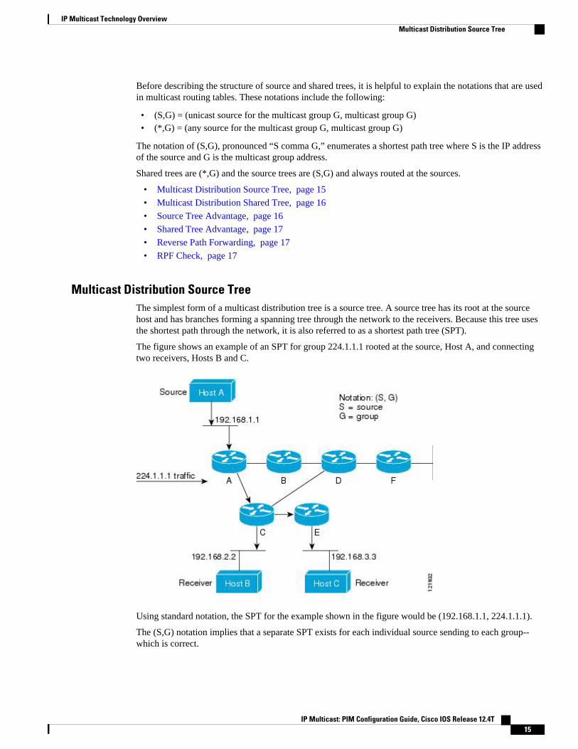
Multicast Distribution Source TreeThe simplest form of a multicast distribution tree is a source tree. A source tree has its root at the sourcehost and has branches forming a spanning tree through the network to the receivers. Because this tree usesthe shortest path through the network, it is also referred to as a shortest path tree (SPT).
The figure shows an example of an SPT for group 224.1.1.1 rooted at the source, Host A, and connectingtwo receivers, Hosts B and C.
Using standard notation, the SPT for the example shown in the figure would be (192.168.1.1, 224.1.1.1).
The (S,G) notation implies that a separate SPT exists for each individual source sending to each group--which is correct.
IP Multicast Technology OverviewMulticast Distribution Source Tree
IP Multicast: PIM Configuration Guide, Cisco IOS Release 12.4T 15
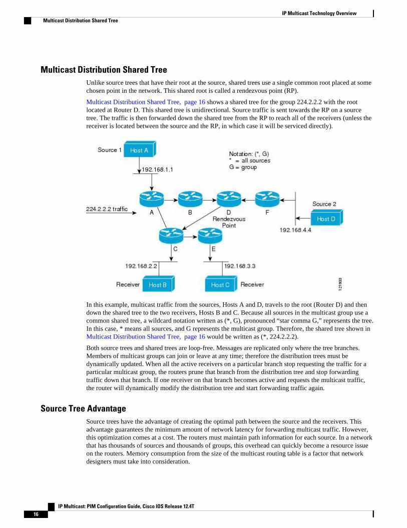
Multicast Distribution Shared TreeUnlike source trees that have their root at the source, shared trees use a single common root placed at somechosen point in the network. This shared root is called a rendezvous point (RP).
Multicast Distribution Shared Tree, page 16 shows a shared tree for the group 224.2.2.2 with the rootlocated at Router D. This shared tree is unidirectional. Source traffic is sent towards the RP on a sourcetree. The traffic is then forwarded down the shared tree from the RP to reach all of the receivers (unless thereceiver is located between the source and the RP, in which case it will be serviced directly).
In this example, multicast traffic from the sources, Hosts A and D, travels to the root (Router D) and thendown the shared tree to the two receivers, Hosts B and C. Because all sources in the multicast group use acommon shared tree, a wildcard notation written as (*, G), pronounced “star comma G,” represents the tree.In this case, * means all sources, and G represents the multicast group. Therefore, the shared tree shown in Multicast Distribution Shared Tree, page 16 would be written as (*, 224.2.2.2).
Both source trees and shared trees are loop-free. Messages are replicated only where the tree branches.Members of multicast groups can join or leave at any time; therefore the distribution trees must bedynamically updated. When all the active receivers on a particular branch stop requesting the traffic for aparticular multicast group, the routers prune that branch from the distribution tree and stop forwardingtraffic down that branch. If one receiver on that branch becomes active and requests the multicast traffic,the router will dynamically modify the distribution tree and start forwarding traffic again.
Source Tree AdvantageSource trees have the advantage of creating the optimal path between the source and the receivers. Thisadvantage guarantees the minimum amount of network latency for forwarding multicast traffic. However,this optimization comes at a cost. The routers must maintain path information for each source. In a networkthat has thousands of sources and thousands of groups, this overhead can quickly become a resource issueon the routers. Memory consumption from the size of the multicast routing table is a factor that networkdesigners must take into consideration.
IP Multicast Technology Overview Multicast Distribution Shared Tree
IP Multicast: PIM Configuration Guide, Cisco IOS Release 12.4T16
Shared Tree AdvantageShared trees have the advantage of requiring the minimum amount of state in each router. This advantagelowers the overall memory requirements for a network that only allows shared trees. The disadvantage ofshared trees is that under certain circumstances the paths between the source and receivers might not be theoptimal paths, which might introduce some latency in packet delivery. For example, in the figure above theshortest path between Host A (source 1) and Host B (a receiver) would be Router A and Router C. Becausewe are using Router D as the root for a shared tree, the traffic must traverse Routers A, B, D and then C.Network designers must carefully consider the placement of the rendezvous point (RP) when implementinga shared tree-only environment.
In unicast routing, traffic is routed through the network along a single path from the source to thedestination host. A unicast router does not consider the source address; it considers only the destinationaddress and how to forward the traffic toward that destination. The router scans through its routing table forthe destination address and then forwards a single copy of the unicast packet out the correct interface in thedirection of the destination.
In multicast forwarding, the source is sending traffic to an arbitrary group of hosts that are represented by amulticast group address. The multicast router must determine which direction is the upstream direction(toward the source) and which one is the downstream direction (or directions) toward the receivers. If thereare multiple downstream paths, the router replicates the packet and forwards it down the appropriatedownstream paths (best unicast route metric)--which is not necessarily all paths. Forwarding multicasttraffic away from the source, rather than to the receiver, is called Reverse Path Forwarding (RPF). RPF isdescribed in the following section.
Reverse Path ForwardingIn unicast routing, traffic is routed through the network along a single path from the source to thedestination host. A unicast router does not consider the source address; it considers only the destinationaddress and how to forward the traffic toward that destination. The router scans through its routing table forthe destination network and then forwards a single copy of the unicast packet out the correct interface in thedirection of the destination.
In multicast forwarding, the source is sending traffic to an arbitrary group of hosts that are represented by amulticast group address. The multicast router must determine which direction is the upstream direction(toward the source) and which one is the downstream direction (or directions) toward the receivers. If thereare multiple downstream paths, the router replicates the packet and forwards it down the appropriatedownstream paths (best unicast route metric)--which is not necessarily all paths. Forwarding multicasttraffic away from the source, rather than to the receiver, is called Reverse Path Forwarding (RPF). RPF isan algorithm used for forwarding multicast datagrams.
Protocol Independent Multicast (PIM) uses the unicast routing information to create a distribution treealong the reverse path from the receivers towards the source. The multicast routers then forward packetsalong the distribution tree from the source to the receivers. RPF is a key concept in multicast forwarding. Itenables routers to correctly forward multicast traffic down the distribution tree. RPF makes use of theexisting unicast routing table to determine the upstream and downstream neighbors. A router will forward amulticast packet only if it is received on the upstream interface. This RPF check helps to guarantee that thedistribution tree will be loop-free.
RPF CheckWhen a multicast packet arrives at a router, the router performs an RPF check on the packet. If the RPFcheck succeeds, the packet is forwarded. Otherwise, it is dropped.
IP Multicast Technology OverviewShared Tree Advantage
IP Multicast: PIM Configuration Guide, Cisco IOS Release 12.4T 17
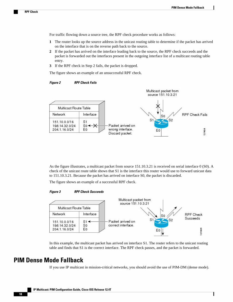
For traffic flowing down a source tree, the RPF check procedure works as follows:
1 The router looks up the source address in the unicast routing table to determine if the packet has arrivedon the interface that is on the reverse path back to the source.
2 If the packet has arrived on the interface leading back to the source, the RPF check succeeds and thepacket is forwarded out the interfaces present in the outgoing interface list of a multicast routing tableentry.
3 If the RPF check in Step 2 fails, the packet is dropped.
The figure shows an example of an unsuccessful RPF check.
Figure 2 RPF Check Fails
As the figure illustrates, a multicast packet from source 151.10.3.21 is received on serial interface 0 (S0). Acheck of the unicast route table shows that S1 is the interface this router would use to forward unicast datato 151.10.3.21. Because the packet has arrived on interface S0, the packet is discarded.
The figure shows an example of a successful RPF check.
Figure 3 RPF Check Succeeds
In this example, the multicast packet has arrived on interface S1. The router refers to the unicast routingtable and finds that S1 is the correct interface. The RPF check passes, and the packet is forwarded.
PIM Dense Mode FallbackIf you use IP multicast in mission-critical networks, you should avoid the use of PIM-DM (dense mode).
PIM Dense Mode Fallback RPF Check
IP Multicast: PIM Configuration Guide, Cisco IOS Release 12.4T18
Dense mode fallback describes the event of the PIM mode changing (falling back) from sparse mode(which requires an RP) to dense mode (which does not use an RP). Dense mode fallback occurs when RPinformation is lost.
If all interfaces are configured with the ip pim sparse-mode command, there is no dense mode fallbackbecause dense mode groups cannot be created over interfaces configured for sparse mode.
Cause and Effect of Dense Mode Fallback
PIM determines whether a multicast group operates in PIM-DM or PIM-SM mode based solely on theexistence of RP information in the group-to-RP mapping cache. If Auto-RP is configured or a bootstraprouter (BSR) is used to distribute RP information, there is a risk that RP information can be lost if all RPs,Auto-RP, or the BSR for a group fails due to network congestion. This failure can lead to the networkeither partially or fully falling back into PIM-DM.
If a network falls back into PIM-DM and AutoRP or BSR is being used, dense mode flooding will occur.Routers that lose RP information will fallback into dense mode and any new states that must be created forthe failed group will be created in dense mode.
Effects of Preventing Dense Mode Fallback
Prior to the introduction of PIM-DM fallback prevention, all multicast groups without a group-to-RPmapping would be treated as dense mode.
With the introduction of PIM-DM fallback prevention, the PIM-DM fallback behavior has been changed toprevent dense mode flooding. By default, if all of the interfaces are configured to operate in PIM sparsemode (using the ip pim sparse-mode command), there is no need to configure the no ip pim dm-fallbackcommand (that is, the PIM-DM fallback behavior is enabled by default). If any interfaces are notconfigured using the ip pim sparse-modecommand (for example, using the ip pim sparse-dense-modecommand), then the PIM-DM fallback behavior can be explicit disabled using the no ip pim dm-fallbackcommand.
When the no ip pim dm-fallback command is configured or when ip pim sparse-mode is configured onall interfaces, any existing groups running in sparse mode will continue to operate in sparse mode but willuse an RP address set to 0.0.0.0. Multicast entries with an RP address set to 0.0.0.0 will exhibit thefollowing behavior:
• Existing (S, G) states will be maintained.• No PIM Join or Prune messages for (*, G) or (S, G, RPbit) are sent.• Received (*, G) or (S, G, RPbit) Joins or Prune messages are ignored.• No registers are sent and traffic at the first hop is dropped.• Received registers are answered with register stop.• Asserts are unchanged.• The (*, G) outgoing interface list (olist) is maintained only for the Internet Group Management
Protocol (IGMP) state.• Multicast Source Discovery Protocol (MSDP) source active (SA) messages for RP 0.0.0.0 groups are
still accepted and forwarded.
Guidelines for Choosing a PIM ModeBefore beginning the configuration process, you must decide which PIM mode needs to be used. Thisdetermination is based on the applications you intend to support on your network.
Basic guidelines include the following:
Guidelines for Choosing a PIM ModeRPF Check
IP Multicast: PIM Configuration Guide, Cisco IOS Release 12.4T 19
• In general, if the application is one-to-many or many-to-many in nature, then PIM-SM can be usedsuccessfully.
• For optimal one-to-many application performance, SSM is appropriate but requires IGMP version 3support.
• For optimal many-to-many application performance, bidirectional PIM is appropriate but hardwaresupport is limited to Cisco devices and the Catalyst 6000 series switches with Sup720.
Where to Go Next• To configure basic IP multicast, see the “ Configuring Basic IP Multicast ” module.
Additional ReferencesRelated Documents
Related Topic Document Title
IP multicast commands: complete command syntax,command mode, command history, defaults, usageguidelines and examples
Cisco IOS IP Multicast Command Reference
MIBs
MIB MIBs Link
-- To locate and download MIBs for selectedplatforms, Cisco IOS releases, and feature sets, useCisco MIB Locator found at the following URL:
http://www.cisco.com/go/mibs
RFCs
RFC Title
RFC 1112 Host Extensions for IP Multicasting
RFC 2113 IP Router Alert Option
RFC 2362 Protocol Independent Multicast-Sparse Mode (PIM-SM): Protocol Specification
RFC 3180 GLOP Addressing in 233/8
IP Multicast Technology Overview Where to Go Next
IP Multicast: PIM Configuration Guide, Cisco IOS Release 12.4T20
Technical Assistance
Description Link
The Cisco Support website provides extensiveonline resources, including documentation and toolsfor troubleshooting and resolving technical issueswith Cisco products and technologies.
To receive security and technical information aboutyour products, you can subscribe to variousservices, such as the Product Alert Tool (accessedfrom Field Notices), the Cisco Technical ServicesNewsletter, and Really Simple Syndication (RSS)Feeds.
Access to most tools on the Cisco Support websiterequires a Cisco.com user ID and password.
http://www.cisco.com/cisco/web/support/index.html
Feature Information for IP Multicast Technology OverviewThe following table provides release information about the feature or features described in this module.This table lists only the software release that introduced support for a given feature in a given softwarerelease train. Unless noted otherwise, subsequent releases of that software release train also support thatfeature.
Use Cisco Feature Navigator to find information about platform support and Cisco software image support.To access Cisco Feature Navigator, go to www.cisco.com/go/cfn. An account on Cisco.com is not required.
Table 2 Feature Information for IP Multicast Technology Overview
Feature Names Releases Feature Configuration Information
PIM Dense Mode FallbackPrevention in a NetworkFollowing RP Information Loss
12.3(4)T The PIM Dense Mode FallbackPrevention in a NetworkFollowing RP Information Lossfeature enables you to preventPIM-DM fallback when all RPsfail. Preventing the use of densemode is very important tomulticast networks whosereliability is critical. This featureprovides a mechanism to keep themulticast groups in sparse mode,thereby preventing dense modeflooding.
Glossary
IP Multicast Technology OverviewFeature Information for IP Multicast Technology Overview
IP Multicast: PIM Configuration Guide, Cisco IOS Release 12.4T 21
basic multicast--Interactive intra-domain multicast. Supports multicast applications within an enterprisecampus. Also provides an additional integrity in the network with the inclusion of a reliable multicasttransport, PGM.
bidir PIM--Bidirectional PIM is an extension to the PIM suite of protocols that implements shared sparsetrees with bidirectional flow of data. In contrast to PIM-SM, bidir-PIM avoids keeping source specific statein router and thus allows trees to scale to an arbitrary number of sources.
broadcast--One-to-all transmission where the source sends one copy of the message to all nodes, whetherthey wish to receive it or not.
Cisco Group Management Protocol (CGMP)--Cisco-developed protocol that allows Layer 2 switches toleverage IGMP information on Cisco routers to make Layer 2 forwarding decisions. It allows the switchesto forward multicast traffic to only those ports that are interested in the traffic.
dense mode (DM) (Internet Draft Spec)--Actively attempts to send multicast data to all potential receivers(flooding) and relies upon their self-pruning (removal from group) to achieve desired distribution.
designated router (DR)--The router in a PIM-SM tree that instigates the Join/Prune message cascadeupstream to the RP in response to IGMP membership information it receives from IGMP hosts.
distribution tree--Multicast traffic flows from the source to the multicast group over a distribution tree thatconnects all of the sources to all of the receivers in the group. This tree may be shared by all sources (ashared-tree), or a separate distribution tree can be built for each source (a source-tree). The shared-tree maybe one-way or bidirectional.
IGMP messages--IGMP messages are encapsulated in standard IP datagrams with an IP protocol number of2 and the IP Router Alert option (RFC 2113).
IGMP snooping--IGMP snooping requires the LAN switch to examine, or “snoop,” some Layer 3information in the IGMP packet sent from the host to the router. When the switch hears an IGMP reportfrom a host for a particular multicast group, the switch adds the host’s port number to the associatedmulticast table entry. When it hears an IGMP Leave Group message from a host, it removes the host’s portfrom the table entry.
IGMP unidirectional link routing--Cisco’s other UDLR solution is to use IP multicast routing with IGMP,which has been enhanced to accommodate UDLR. This solution scales very well for many satellite links.
Internet Group Management Protocol v2 (IGMP)--Used by IP routers and their immediately connectedhosts to communicate multicast group membership states.
Internet Group Management Protocol v3 (IGMP)--IGMP is the protocol used by IPv4 systems to reporttheir IP multicast group memberships to neighboring multicast routers. Version 3 of IGMP adds support for“source filtering,” that is, the ability for a system to report interest in receiving packets only from specificsource addresses, or from all but specific source addresses, sent to a particular multicast address.
multicast--A routing technique that allows IP traffic to be sent from one source or multiple sources anddelivered to multiple destinations. Instead of sending individual packets to each destination, a single packetis sent to a group of destinations known as a multicast group, which is identified by a single IP destinationgroup address. Multicast addressing supports the transmission of a single IP datagram to multiple hosts.
multicast routing monitor (MRM)--A management diagnostic tool that provides network fault detection andisolation in a large multicast routing infrastructure. It is designed to notify a network administrator ofmulticast routing problems in near real time.
Multicast Source Discovery Protocol (MSDP)--A mechanism to connect multiple PIM sparse mode (PIM-SM) domains. MSDP allows multicast sources for a group to be known to all rendezvous point(s) (RPs) indifferent domains. Each PIM-SM domain uses its own RPs and need not depend on RPs in other domains.An RP runs MSDP over TCP to discover multicast sources in other domains. MSDP is also used to
IP Multicast Technology Overview Glossary
IP Multicast: PIM Configuration Guide, Cisco IOS Release 12.4T22
announce sources sending to a group. These announcements must originate at the domain’s RP. MSDPdepends heavily on MBGP for interdomain operation.
Protocol Independent Multicast (PIM)--A multicast routing architecture defined by the IETF that enables IPmulticast routing on existing IP networks. Its key point is its independence from any underlying unicastprotocol such as OSPF or BGP.
prune--Multicast routing terminology indicating that the multicast-enabled router has sent the appropriatemulticast messages to remove itself from the multicast tree for a particular multicast group. It will stopreceiving the multicast data addressed to that group and, therefore, cannot deliver the data to any connectedhosts until it rejoins the group.
query--IGMP messages originating from the router(s) to elicit multicast group membership informationfrom its connected hosts.
rendezvous point (RP)--The multicast router that is the root of the PIM-SM shared multicast distributiontree.
report--IGMP messages originating from the hosts that are joining, maintaining, or leaving theirmembership in a multicast group.
source tree--A multicast distribution path that directly connects the source’s and receivers’ designatedrouter (or the rendezvous point) to obtain the shortest path through the network. Results in most efficientrouting of data between source and receivers, but may result in unnecessary data duplication throughout thenetwork if built by anything other than the RP.
sparse mode (SM) (RFC 2362)--Relies upon an explicitly joining method before attempting to sendmulticast data to receivers of a multicast group.
UDLR tunnel--Uses a back channel (another link) so the routing protocols believe the one-way link isbidirectional. The back channel itself is a special, unidirectional, generic route encapsulation (GRE) tunnelthrough which control traffic flows in the opposite direction of the user data flow. This feature allows IPand its associated unicast and multicast routing protocols to believe the unidirectional link is logicallybidirectional. This solution accommodates all IP unicast and multicast routing protocols without changingthem. However, it does not scale and no more than 20 tunnels should feed into the upstream router. Thepurpose of the unidirectional GRE tunnel is to move control packets from a downstream node to anupstream node.
Unicast--Point-to-point transmission requiring the source to send an individual copy of a message to eachrequester.
unidirectional Link Routing Protocol (UDLR)--A routing protocol that provides a way to forward multicastpackets over a physical unidirectional interface (such as a satellite link of high bandwidth) to stub networksthat have a back channel.
URL rendezvous directory (URD)--URD is a multicast-lite solution that directly provides the network withinformation about the specific source of a content stream. It enables the network to quickly establish themost direct distribution path from the source to the receiver, thus significantly reducing the time and effortrequired in receiving the streaming media. URD allows an application to identify the source of the contentstream through a web page link or web directly. When that information is sent back to the application it isthen conveyed back to the network using URD.
In this feature, a URD-capable web page provides information about the source, the group, and theapplication (via media-type) on a web page. An interested host will click on the web page pulling across theinformation in an HTTP transaction. The last-hop router to receiver would intercept this transaction andsend it to a special port allocated by IANA. The last-hop router is also URD capable and uses theinformation to initiate the PIM source, group (S,G) join on behalf of the host.
IP Multicast Technology OverviewGlossary
IP Multicast: PIM Configuration Guide, Cisco IOS Release 12.4T 23

Cisco and the Cisco logo are trademarks or registered trademarks of Cisco and/or its affiliates in the U.S.and other countries. To view a list of Cisco trademarks, go to this URL: www.cisco.com/go/trademarks.Third-party trademarks mentioned are the property of their respective owners. The use of the word partnerdoes not imply a partnership relationship between Cisco and any other company. (1110R)
Any Internet Protocol (IP) addresses and phone numbers used in this document are not intended to beactual addresses and phone numbers. Any examples, command display output, network topology diagrams,and other figures included in the document are shown for illustrative purposes only. Any use of actual IPaddresses or phone numbers in illustrative content is unintentional and coincidental.
IP Multicast Technology Overview
IP Multicast: PIM Configuration Guide, Cisco IOS Release 12.4T24
Configuring Basic IP Multicast
IP multicast is a bandwidth-conserving technology that reduces traffic by delivering a single stream ofinformation simultaneously to potentially thousands of corporate businesses and homes. Applications thattake advantage of multicast include video conferencing, corporate communications, distance learning, anddistribution of software, stock quotes, and news. This module describes the tasks used to configure basicIP multicast.
• Finding Feature Information, page 25• Prerequisites for Configuring Basic IP Multicast, page 25• Information About Configuring Basic IP Multicast, page 26• How to Configure Basic IP Multicast, page 35• Configuration Examples for Basic IP Multicast, page 56• Additional References, page 62• Feature Information for Configuring Basic IP Multicast, page 63
Finding Feature InformationYour software release may not support all the features documented in this module. For the latest featureinformation and caveats, see the release notes for your platform and software release. To find informationabout the features documented in this module, and to see a list of the releases in which each feature issupported, see the Feature Information Table at the end of this document.
Use Cisco Feature Navigator to find information about platform support and Cisco software image support.To access Cisco Feature Navigator, go to www.cisco.com/go/cfn. An account on Cisco.com is not required.
Prerequisites for Configuring Basic IP Multicast• Before performing the tasks in this module, you should be familiar with the concepts explained in the
“IP Multicast Technology Overview” module.• To determine which of the tasks contained in this module you will have to perform, you must decide
which Protocol Independent Multicast (PIM) mode will be used. This determination is based on theapplications you intend to support on your network.
• All access lists you intend to use with the tasks in this module should be configured prior to beginningthe configuration task. For information about how to configure an access list, see the “ Creating an IPAccess List and Applying It to an Interface ” module.
IP Multicast: PIM Configuration Guide, Cisco IOS Release 12.4T 25
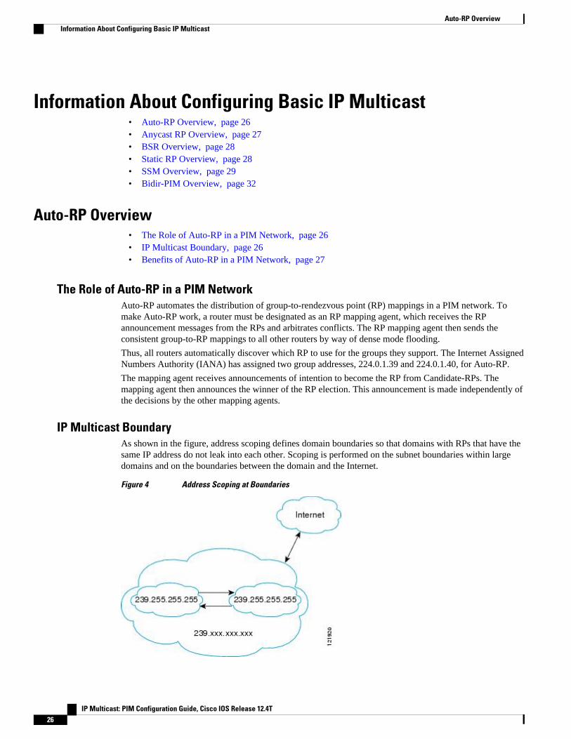
Information About Configuring Basic IP Multicast• Auto-RP Overview, page 26• Anycast RP Overview, page 27• BSR Overview, page 28• Static RP Overview, page 28• SSM Overview, page 29• Bidir-PIM Overview, page 32
Auto-RP Overview• The Role of Auto-RP in a PIM Network, page 26• IP Multicast Boundary, page 26• Benefits of Auto-RP in a PIM Network, page 27
The Role of Auto-RP in a PIM NetworkAuto-RP automates the distribution of group-to-rendezvous point (RP) mappings in a PIM network. Tomake Auto-RP work, a router must be designated as an RP mapping agent, which receives the RPannouncement messages from the RPs and arbitrates conflicts. The RP mapping agent then sends theconsistent group-to-RP mappings to all other routers by way of dense mode flooding.
Thus, all routers automatically discover which RP to use for the groups they support. The Internet AssignedNumbers Authority (IANA) has assigned two group addresses, 224.0.1.39 and 224.0.1.40, for Auto-RP.
The mapping agent receives announcements of intention to become the RP from Candidate-RPs. Themapping agent then announces the winner of the RP election. This announcement is made independently ofthe decisions by the other mapping agents.
IP Multicast BoundaryAs shown in the figure, address scoping defines domain boundaries so that domains with RPs that have thesame IP address do not leak into each other. Scoping is performed on the subnet boundaries within largedomains and on the boundaries between the domain and the Internet.
Figure 4 Address Scoping at Boundaries
Auto-RP Overview Information About Configuring Basic IP Multicast
IP Multicast: PIM Configuration Guide, Cisco IOS Release 12.4T26
You can set up an administratively scoped boundary on an interface for multicast group addresses using theip multicast boundary command with the access-list argument. A standard access list defines the range ofaddresses affected. When a boundary is set up, no multicast data packets are allowed to flow across theboundary from either direction. The boundary allows the same multicast group address to be reused indifferent administrative domains.
The Internet Assigned Numbers Authority (IANA) has designated the multicast address range 239.0.0.0 to239.255.255.255 as the administratively scoped addresses. This range of addresses can be reused indomains administered by different organizations. They would be considered local, not globally unique.
You can configure the filter-autorp keyword to examine and filter Auto-RP discovery and announcementmessages at the administratively scoped boundary. Any Auto-RP group range announcements from theAuto-RP packets that are denied by the boundary access control list (ACL) are removed. An Auto-RPgroup range announcement is permitted and passed by the boundary only if all addresses in the Auto-RPgroup range are permitted by the boundary ACL. If any address is not permitted, the entire group range isfiltered and removed from the Auto-RP message before the Auto-RP message is forwarded.
Benefits of Auto-RP in a PIM Network
• Auto-RP allows any change to the RP designation to be configured only on the routers that are RPs,not on the leaf routers.
• Auto-RP offers the ability to scope the RP address within a domain. Scoping can be achieved by usingthe ip multicast boundary command with the filter-autorp keyword.
Anycast RP OverviewAnycast RP is a useful application of MSDP. Originally developed for interdomain multicast applications,MSDP used for Anycast RP is an intradomain feature that provides redundancy and load-sharingcapabilities. Enterprise customers typically use Anycast RP for configuring a Protocol IndependentMulticast sparse mode (PIM-SM) network to meet fault tolerance requirements within a single multicastdomain.
In anycast RP, two or more RPs are configured with the same IP address on loopback interfaces. Theanycast RP loopback address should be configured with a 32-bit mask, making it a host address. All thedownstream routers should be configured so that the anycast RP loopback address is the IP address of theirlocal RP. IP routing will automatically select the topologically closest RP for each source and receiver.Assuming that the sources are evenly spaced around the network, an equal number of sources will registerwith each RP. That is, the process of registering the sources will be shared equally by all the RPs in thenetwork.
Because a source may register with one RP and receivers may join to a different RP, a method is needed forthe RPs to exchange information about active sources. This information exchange is done with MSDP.
In anycast RP, all the RPs are configured to be MSDP peers of each other. When a source registers withone RP, an SA message will be sent to the other RPs informing them that there is an active source for aparticular multicast group. The result is that each RP will know about the active sources in the area of theother RPs. If any of the RPs were to fail, IP routing would converge, and one of the RPs would become theactive RP in more than one area. New sources would register with the backup RP. Receivers would join thenew RP and connectivity would be maintained.
The RP is normally needed only to start new sessions with sources and receivers. The RP facilitates theshared tree so that sources and receivers can establish a direct multicast data flow. If a multicast data flowis already established between a source and the receiver, an RP failure will not affect that session. AnycastRP ensures that new sessions with sources and receivers can begin at any time.
Anycast RP OverviewBenefits of Auto-RP in a PIM Network
IP Multicast: PIM Configuration Guide, Cisco IOS Release 12.4T 27
BSR Overview• BSR Election and Functionality, page 28
• BSR Border Interface, page 28
BSR Election and FunctionalityPIM uses the BSR to discover and announce RP-set information for each group prefix to all the routers in aPIM domain. This is the same function performed by Auto-RP, but the BSR is part of the PIM Version 2specification. The BSR mechanism interoperates with Auto-RP on Cisco routers.
To avoid a single point of failure, you can configure several candidate BSRs in a PIM domain. A BSR iselected among the candidate BSRs automatically; they use bootstrap messages to discover which BSR hasthe highest priority. This router then announces to all PIM routers in the PIM domain that it is the BSR.
Following the election of the BSR, candidate RPs use unicast to announce to the BSR their willingness tobe the RP. The BSR advertises the entire group-to-RP mapping set to the router link local address224.0.0.13. Unlike the RP mapping agent in Auto-RP, which is used by Auto-RP to select the RP, everyrouter in the BSR network is responsible for selecting the RP.
BSR lacks the ability to scope RP advertisements; however, BSR is used when vendor interoperability oropen standard adherence is a requirement.
BSR Border InterfaceA border interface in a PIM sparse mode domain requires precautions to prevent exchange of certain trafficwith a neighboring domain reachable through that interface, especially if that domain is also running PIMsparse mode. BSR and Auto-RP messages should not be exchanged between different domains, becauserouters in one domain may elect RPs in the other domain, resulting in protocol malfunction or loss ofisolation between the domains. Configure a BSR border interface to prevent BSR messages from being sentor received through an interface.
Static RP OverviewIf you are configuring PIM sparse mode, you must configure a PIM RP for a multicast group. An RP caneither be configured statically in each device, or learned through a dynamic mechanism. This task explainshow to statically configure an RP, as opposed to the router learning the RP through a dynamic mechanismsuch as Auto-RP.
PIM designated routers (DRs) forward data from directly connected multicast sources to the RP fordistribution down the shared tree. Data is forwarded to the RP in one of two ways. It is encapsulated inregister packets and unicast directly to the RP, or, if the RP has itself joined the source tree, it is multicastforwarded per the RPF forwarding algorithm. Last hop routers directly connected to receivers may, at theirdiscretion, join themselves to the source tree and prune themselves from the shared tree.
A single RP can be configured for multiple groups that are defined by an access list. If no RP is configuredfor a group, the router treats the group as dense using the PIM dense mode techniques. (You can preventthis occurrence by configuring the no ip pim dm-fallbackcommand.)
If dynamic and static group-to-RP mappings are used together and there is an RP address conflict, the RPaddress configured for a static group-to-RP mapping (with the ip pim rp-address overridecommand) willtake precedence.
BSR Overview BSR Election and Functionality
IP Multicast: PIM Configuration Guide, Cisco IOS Release 12.4T28
Note If the override keyword is not specified and there is RP address conflict, dynamic group-to-RP mappingswill take precedence over static group-to-RP mappings.
SSM OverviewSource Specific Multicast (SSM). SSM is an extension of IP multicast where datagram traffic is forwardedto receivers from only those multicast sources that the receivers have explicitly joined. For multicast groupsconfigured for SSM, only source-specific multicast distribution trees (not shared trees) are created.
• SSM Components, page 29
• How SSM Differs from Internet Standard Multicast, page 29
• SSM Operations, page 30
• IGMPv3 Host Signaling, page 30
• Benefits of Source Specific Multicast, page 31
SSM ComponentsSSM is a datagram delivery model that best supports one-to-many applications, also known as broadcastapplications. SSM is a core networking technology for the Cisco implementation of IP multicast solutionstargeted for audio and video broadcast application environments and is described in RFC 3569. Thefollowing two components together support the implementation of SSM:
• Protocol Independent Multicast source-specific mode (PIM-SSM)• Internet Group Management Protocol Version 3 (IGMPv3)
Protocol Independent Multicast (PIM) SSM, or PIM-SSM, is the routing protocol that supports theimplementation of SSM and is derived from PIM sparse mode (PIM-SM). IGMP is the InternetEngineering Task Force (IETF) standards track protocol used for hosts to signal multicast groupmembership to routers. IGMP Version 3 supports source filtering, which is required for SSM. IGMP ForSSM to run with IGMPv3, SSM must be supported in the router, the host where the application is running,and the application itself.
How SSM Differs from Internet Standard MulticastThe standard IP multicast infrastructure in the Internet and many enterprise intranets is based on the PIM-SM protocol and Multicast Source Discovery Protocol (MSDP). These protocols have proved to be reliable,extensive, and efficient. However, they are bound to the complexity and functionality limitations of theInternet Standard Multicast (ISM) service model. For example, with ISM, the network must maintainknowledge about which hosts in the network are actively sending multicast traffic. With SSM, thisinformation is provided by receivers through the source addresses relayed to the last-hop routers byIGMPv3. SSM is an incremental response to the issues associated with ISM and is intended to coexist inthe network with the protocols developed for ISM. In general, SSM provides IP multicast service forapplications that utilize SSM.
ISM service is described in RFC 1112. This service consists of the delivery of IP datagrams from anysource to a group of receivers called the multicast host group. The datagram traffic for the multicast hostgroup consists of datagrams with an arbitrary IP unicast source address S and the multicast group address Gas the IP destination address. Systems will receive this traffic by becoming members of the host group.Membership in a host group simply requires signaling the host group through IGMP Version 1, 2, or 3.
SSM OverviewSSM Components
IP Multicast: PIM Configuration Guide, Cisco IOS Release 12.4T 29
In SSM, delivery of datagrams is based on (S, G) channels. Traffic for one (S, G) channel consists ofdatagrams with an IP unicast source address S and the multicast group address G as the IP destinationaddress. Systems will receive this traffic by becoming members of the (S, G) channel. In both SSM andISM, no signaling is required to become a source. However, in SSM, receivers must subscribe orunsubscribe to (S, G) channels to receive or not receive traffic from specific sources. In other words,receivers can receive traffic only from (S, G) channels to which they are subscribed, whereas in ISM,receivers need not know the IP addresses of sources from which they receive their traffic. The proposedstandard approach for channel subscription signaling utilizes IGMP INCLUDE mode membership reports,which are supported only in IGMP Version 3.
SSM can coexist with the ISM service by applying the SSM delivery model to a configured subset of the IPmulticast group address range. The Internet Assigned Numbers Authority (IANA) has reserved the addressrange from 232.0.0.0 through 232.255.255.255 for SSM applications and protocols. The software allowsSSM configuration for an arbitrary subset of the IP multicast address range from 224.0.0.0 through239.255.255.255. When an SSM range is defined, an existing IP multicast receiver application will notreceive any traffic when it tries to use addresses in the SSM range unless the application is modified to useexplicit (S, G) channel subscription or is SSM-enabled through a URL Rendezvous Directory (URD).
SSM OperationsAn established network in which IP multicast service is based on PIM-SM can support SSM services. SSMcan also be deployed alone in a network without the full range of protocols that are required forinterdomain PIM-SM. That is, SSM does not require an RP, so there is no need for an RP mechanism suchas Auto-RP, MSDP, or bootstrap router (BSR).
If SSM is deployed in a network that is already configured for PIM-SM, then only the last-hop routers mustbe upgraded to a software image that supports SSM. Routers that are not directly connected to receivers donot have to upgrade to a software image that supports SSM. In general, these non-last-hop routers mustonly run PIM-SM in the SSM range. They may need additional access control configuration to suppressMSDP signaling, registering, or PIM-SM shared-tree operations from occurring within the SSM range.
The SSM mode of operation is enabled by configuring the SSM range using the ip pim ssm globalconfiguration command. This configuration has the following effects:
• For groups within the SSM range, (S, G) channel subscriptions are accepted through IGMPv3INCLUDE mode membership reports.
• PIM operations within the SSM range of addresses change to PIM-SSM, a mode derived from PIM-SM. In this mode, only PIM (S, G) Join and Prune messages are generated by the router. Incomingmessages related to rendezvous point tree (RPT) operations are ignored or rejected, and incoming PIMregister messages are immediately answered with Register-Stop messages. PIM-SSM is backward-compatible with PIM-SM unless a router is a last-hop router. Therefore, routers that are not last-hoprouters can run PIM-SM for SSM groups (for example, if they do not yet support SSM).
• For groups within the SSM range, no MSDP Source-Active (SA) messages within the SSM range willbe accepted, generated, or forwarded.
IGMPv3 Host SignalingIGMPv3 is the third version of the IETF standards track protocol in which hosts signal membership to last-hop routers of multicast groups. IGMPv3 introduces the ability for hosts to signal group membership thatallows filtering capabilities with respect to sources. A host can signal either that it wants to receive trafficfrom all sources sending to a group except for some specific sources (a mode called EXCLUDE) or that itwants to receive traffic only from some specific sources sending to the group (a mode called INCLUDE).
Configuring Basic IP Multicast SSM Operations
IP Multicast: PIM Configuration Guide, Cisco IOS Release 12.4T30
IGMPv3 can operate with both ISM and SSM. In ISM, both EXCLUDE and INCLUDE mode reports areaccepted by the last-hop router. In SSM, only INCLUDE mode reports are accepted by the last-hop router.
Benefits of Source Specific Multicast
IP Multicast Address Management Not Required
In the ISM service, applications must acquire a unique IP multicast group address because trafficdistribution is based only on the IP multicast group address used. If two applications with different sourcesand receivers use the same IP multicast group address, then receivers of both applications will receivetraffic from the senders of both applications. Even though the receivers, if programmed appropriately, canfilter out the unwanted traffic, this situation would cause generally unacceptable levels of unwanted traffic.
Allocating a unique IP multicast group address for an application is still a problem. Most short-livedapplications use mechanisms like Session Description Protocol (SDP) and Session Announcement Protocol(SAP) to get a random address, a solution that does not work well with a rising number of applications inthe Internet. The best current solution for long-lived applications is described in RFC 2770, but thissolution suffers from the restriction that each autonomous system is limited to only 255 usable IP multicastaddresses.
In SSM, traffic from each source is forwarded between routers in the network independent of traffic fromother sources. Thus different sources can reuse multicast group addresses in the SSM range.
Denial of Service Attacks from Unwanted Sources Inhibited
In SSM, multicast traffic from each individual source will be transported across the network only if it wasrequested (through IGMPv3, IGMP v3lite, or URD memberships) from a receiver. In contrast, ISMforwards traffic from any active source sending to a multicast group to all receivers requesting thatmulticast group. In Internet broadcast applications, this ISM behavior is highly undesirable because itallows unwanted sources to easily disturb the actual Internet broadcast source by simply sending traffic tothe same multicast group. This situation depletes bandwidth at the receiver side with unwanted traffic andthus disrupts the undisturbed reception of the Internet broadcast. In SSM, this type of denial of service(DoS) attack cannot be made by simply sending traffic to a multicast group.
Easy to Install and Manage
SSM is easy to install and provision in a network because it does not require the network to maintain whichactive sources are sending to multicast groups. This requirement exists in ISM (with IGMPv1, IGMPv2, orIGMPv3).
The current standard solutions for ISM service are PIM-SM and MSDP. Rendezvous point (RP)management in PIM-SM (including the necessity for Auto-RP or BSR) and MSDP is required only for thenetwork to learn about active sources. This management is not necessary in SSM, which makes SSM easierthan ISM to install and manage, and therefore easier than ISM to operationally scale in deployment.Another factor that contributes to the ease of installation of SSM is the fact that it can leverage preexistingPIM-SM networks and requires only the upgrade of last hop routers to support IGMPv3, IGMP v3lite, orURD.
Ideal for Internet Broadcast Applications
The three benefits previously described make SSM ideal for Internet broadcast-style applications for thefollowing reasons:
Configuring Basic IP MulticastBenefits of Source Specific Multicast
IP Multicast: PIM Configuration Guide, Cisco IOS Release 12.4T 31
• The ability to provide Internet broadcast services through SSM without the need for unique IPmulticast addresses allows content providers to easily offer their service (IP multicast addressallocation has been a serious problem for content providers in the past).
• The prevention against DoS attacks is an important factor for Internet broadcast services because, withtheir exposure to a large number of receivers, they are the most common targets for such attacks.
• The ease of installation and operation of SSM makes it ideal for network operators, especially in thosecases where content needs to be forwarded between multiple independent PIM domains (because thereis no need to manage MSDP for SSM between PIM domains).
Bidir-PIM OverviewBidir-PIM shares many of its shortest path tree (SPT) operations with PIM-SM. Bidir-PIM also hasunconditional forwarding of source traffic toward the RP upstream on the shared tree, but has no registeringprocess for sources as in PIM-SM. These modifications allow forwarding of traffic in all routers basedsolely on the (*, G) multicast routing entries. This form of forwarding eliminates any source-specific stateand allows scaling capability to an arbitrary number of sources.
• Multicast Group Modes, page 32
• Bidirectional Shared Tree, page 32
• DF Election, page 34
• Bidirectional Group Tree Building, page 34
• Packet Forwarding, page 34
• Benefits of Bidirectional PIM, page 35
Multicast Group ModesIn PIM, packet traffic for a multicast group is routed according to the rules of the mode configured for thatmulticast group. The Cisco implementation of PIM supports four modes for a multicast group:
• PIM bidirectional mode• PIM dense mode• PIM sparse mode• PIM Source Specific Mode (SSM)
A router can simultaneously support all four modes or any combination of them for different multicastgroups.
Bidirectional Shared TreeIn bidirectional mode, traffic is routed only along a bidirectional shared tree that is rooted at the rendezvouspoint (RP) for the group. In bidir-PIM, the IP address of the RP acts as the key to having all routersestablish a loop-free spanning tree topology rooted in that IP address. This IP address need not be a router,but can be any unassigned IP address on a network that is reachable throughout the PIM domain. Thistechnique is the preferred configuration method for establishing a redundant RP configuration for bidir-PIM.
Membership in a bidirectional group is signaled by way of explicit Join messages. Traffic from sources isunconditionally sent up the shared tree toward the RP and passed down the tree toward the receivers oneach branch of the tree.
Bidir-PIM Overview Multicast Group Modes
IP Multicast: PIM Configuration Guide, Cisco IOS Release 12.4T32
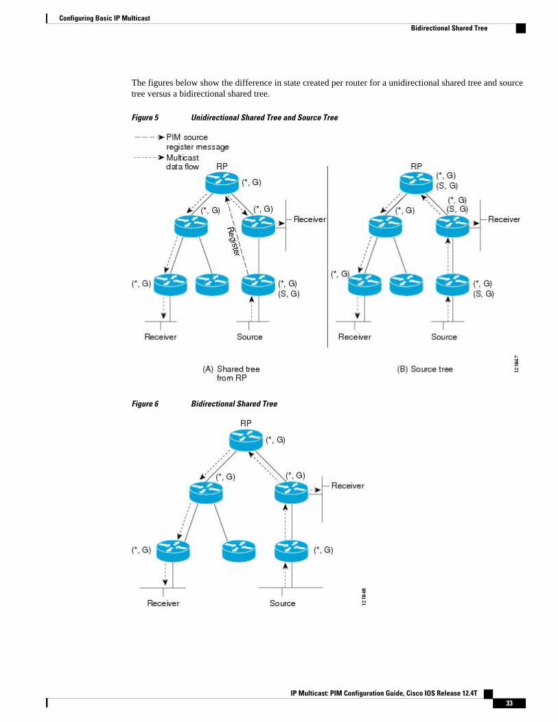
The figures below show the difference in state created per router for a unidirectional shared tree and sourcetree versus a bidirectional shared tree.
Figure 5 Unidirectional Shared Tree and Source Tree
Figure 6 Bidirectional Shared Tree
Configuring Basic IP MulticastBidirectional Shared Tree
IP Multicast: PIM Configuration Guide, Cisco IOS Release 12.4T 33
For packets that are forwarded downstream from the RP toward receivers, there are no fundamentaldifferences between bidir-PIM and PIM-SM. Bidir-PIM deviates substantially from PIM-SM for traffic thatis passed from sources upstream toward the RP.
PIM-SM cannot forward traffic in the upstream direction of a tree because it accepts traffic from only oneReverse Path Forwarding (RPF) interface. This interface (for the shared tree) points toward the RP, thusallowing only downstream traffic flow. Upstream traffic is first encapsulated into unicast register messages,which are passed from the designated router (DR) of the source toward the RP. Second, the RP joins anSPT that is rooted at the source. Therefore, in PIM-SM, traffic from sources destined for the RP does notflow upstream in the shared tree, but downstream along the SPT of the source until it reaches the RP. Fromthe RP, traffic flows along the shared tree toward all receivers.
In bidir-PIM, the packet-forwarding rules have been improved over PIM-SM, allowing traffic to be passedup the shared tree toward the RP. To avoid multicast packet looping, bidir-PIM introduces a newmechanism called designated forwarder (DF) election, which establishes a loop-free SPT rooted at the RP.
DF ElectionOn every network segment and point-to-point link, all PIM routers participate in a procedure calleddesignated forwarder (DF) election. The procedure selects one router as the DF for every RP ofbidirectional groups. This router is responsible for forwarding multicast packets received on that network.
The DF election is based on unicast routing metrics. The router with the most preferred unicast routingmetric to the RP becomes the DF. Use of this method ensures that only one copy of every packet will besent to the RP, even if there are parallel equal-cost paths to the RP.
A DF is selected for every RP of bidirectional groups. As a result, multiple routers may be elected as DF onany network segment, one for each RP. Any particular router may be elected as DF on more than oneinterface.
Bidirectional Group Tree BuildingThe procedure for joining the shared tree of a bidirectional group is almost identical to that used in PIM-SM. One main difference is that, for bidirectional groups, the role of the DR is assumed by the DF for theRP.
On a network that has local receivers, only the router elected as the DF populates the outgoing interface list(olist) upon receiving Internet Group Management Protocol (IGMP) Join messages, and sends (*, G) Joinand Leave messages upstream toward the RP. When a downstream router wishes to join the shared tree, theRPF neighbor in the PIM Join and Leave messages is always the DF elected for the interface that lead tothe RP.
When a router receives a Join or Leave message, and the router is not the DF for the receiving interface, themessage is ignored. Otherwise, the router updates the shared tree in the same way as in sparse mode.
In a network where all routers support bidirectional shared trees, (S, G) Join and Leave messages areignored. There is also no need to send PIM assert messages because the DF election procedure eliminatesparallel downstream paths from any RP. An RP never joins a path back to the source, nor will it send anyregister stops.
Packet ForwardingA router creates (*, G) entries only for bidirectional groups. The olist of a (*, G) entry includes all theinterfaces for which the router has been elected DF and that have received either an IGMP or PIM Joinmessage. If a router is located on a sender-only branch, it will also create a (*, G) state, but the olist will notinclude any interfaces.
Configuring Basic IP Multicast DF Election
IP Multicast: PIM Configuration Guide, Cisco IOS Release 12.4T34
If a packet is received from the RPF interface toward the RP, the packet is forwarded downstreamaccording to the olist of the (*, G) entry. Otherwise, only the router that is the DF for the receiving interfaceforwards the packet upstream toward the RP; all other routers must discard the packet.
Benefits of Bidirectional PIM
• Bidir-PIM removes the performance cost of maintaining a routing state table for a large number ofsources.
• Bidir-PIM is designed to be used for many-to-many applications within individual PIM domains.Multicast groups in bidirectional PIM mode can scale to an arbitrary number of sources withoutincurring overhead due to the number of sources.
How to Configure Basic IP MulticastThe tasks described in this section configure the basic IP multicast modes. No single task in this section isrequired; however, at least one of the tasks must be performed to configure IP multicast in a network. Morethan one of the tasks may be needed.
• Configuring Sparse Mode with Auto-RP, page 35• Configuring Sparse Mode with Anycast RP, page 40• Configuring Sparse Mode with a Bootstrap Router, page 44• Configuring Sparse Mode with a Single Static RP, page 49• Configuring Source Specific Multicast, page 52• Configuring Bidirectional PIM, page 54
Configuring Sparse Mode with Auto-RPThis section contains information about and instructions on how to configure auto-rendezvous point (Auto-RP). Auto-RP can also be optionally used with anycast RP.
Note The simultaneous deployment of Auto-RP and bootstrap router (BSR) is not supported.
• When configuring Auto-RP, you must either configure the Auto-RP listener feature using the ip pimautorp listener command (Step 5) and specify sparse mode using the ip pim sparse-mode command(Step 7) or specify sparse-dense mode (Step 8) using the ip pim sparse-dense mode command.
Note When you configure sparse-dense mode, dense mode failover may result in a network dense-mode flood.To avoid this condition, use PIM sparse mode with the Auto-RP listener feature.
• An interface configured in sparse-dense mode is treated in either sparse mode or dense mode ofoperation, depending on the mode in which the multicast group operates. You must decide how toconfigure your interfaces.
• All access lists that are needed when Auto-RP is configured should be configured prior to beginningthe configuration task. For information about how to configure an access list, see the “ Creating an IPAccess List and Applying It to an Interface ” module.
Configuring Sparse Mode with Auto-RPBenefits of Bidirectional PIM
IP Multicast: PIM Configuration Guide, Cisco IOS Release 12.4T 35

• If a group has no known RP and the interface is configured to be sparse-dense mode, the interface istreated as if it were in dense mode, and data is flooded over the interface. To avoid this data flooding,configure the Auto-RP listener using the ip pim autorp listener command and then configure theinterface as sparse mode using the ip pim sparse mode command.
SUMMARY STEPS
1. enable
2. configure terminal
3. ip multicast-routing [distributed]
4. Either perform Steps 5 through 7 or perform Steps 6 and 8.
5. ip pim autorp listener
6. interface type number
7. ip pim sparse-mode
8. ip pim sparse-dense-mode
9. exit
10. Repeat Steps 1 through 9 on all PIM interfaces.
11. ip pim send-rp-announce {interface-type interface-number | ip-address} scope ttl-value [group-listaccess-list] [interval seconds] [bidir]
12. ip pim send-rp-discovery [interface-type interface-number] scope ttl-value [interval seconds]
13. ip pim rp-announce-filter rp-list access-list group-list access-list
14. no ip pim dm-fallback
15. interface type number
16. ip multicast boundary access-list [filter-autorp]
17. end
18. show ip pim autorp
19. show ip pim rp [mapping] [rp-address]
20. show ip igmp groups [group-name | group-address| interface-type interface-number] [detail]
21. show ip mroute [group-address | group-name] [source-address | source-name] [interface-typeinterface-number] [summary] [count] [active kbps]
DETAILED STEPS
Command or Action Purpose
Step 1 enable
Example:
Router> enable
Enables privileged EXEC mode.
• Enter your password if prompted.
Step 2 configure terminal
Example:
Router# configure terminal
Enters global configuration mode.
Configuring Basic IP Multicast How to Configure Basic IP Multicast
IP Multicast: PIM Configuration Guide, Cisco IOS Release 12.4T36

Command or Action Purpose
Step 3 ip multicast-routing [distributed]
Example:
Router(config)# ip multicast-routing
Enables IP multicast routing.
• Use the distributed keyword to enabled Multicast DistributedSwitching.
Step 4 Either perform Steps 5 through 7 or performSteps 6 and 8.
--
Step 5 ip pim autorp listener
Example:
Router(config)# ip pim autorp listener
Causes IP multicast traffic for the two Auto-RP groups 224.0.1.39 and224.0.1.40 to be PIM dense mode flooded across interfaces operating inPIM sparse mode.
• Skip this step if you are configuring sparse-dense mode in Step 8.
Step 6 interface type number
Example:
Router(config)# interface Gigabitethernet 1/0/0
Selects an interface that is connected to hosts on which PIM can beenabled.
Step 7 ip pim sparse-mode
Example:
Router(config-if)# ip pim sparse-mode
Enables PIM sparse mode on an interface. When configuring Auto-RPin sparse mode, you must also configure the Auto-RP listener in thenext step.
• Skip this step if you are configuring sparse-dense mode in Step 8.
Step 8 ip pim sparse-dense-mode
Example:
Router(config-if)# ip pim sparse-dense-mode
Enables PIM sparse-dense mode on an interface.
• Skip this step if you configured sparse mode in Step 7.
Step 9 exit
Example:
Router(config-if)# exit
Exits interface configuration mode and returns to global configurationmode.
Step 10 Repeat Steps 1 through 9 on all PIM interfaces. --
Configuring Basic IP MulticastHow to Configure Basic IP Multicast
IP Multicast: PIM Configuration Guide, Cisco IOS Release 12.4T 37
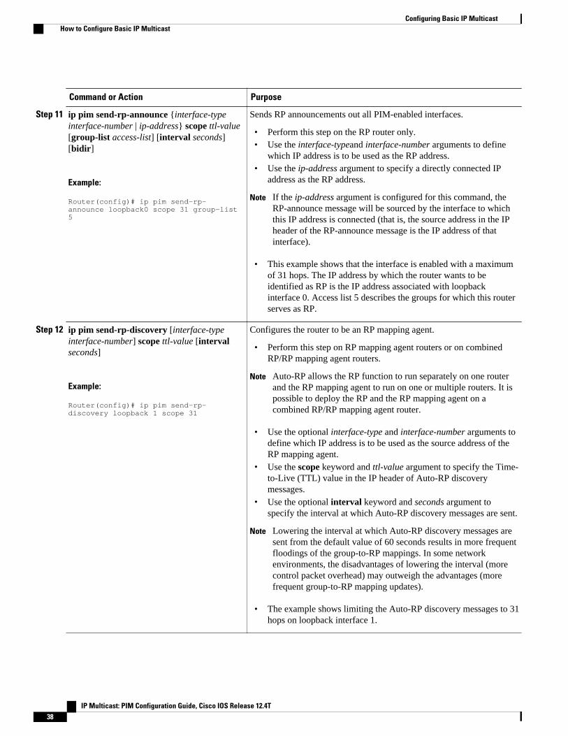
Command or Action Purpose
Step 11 ip pim send-rp-announce {interface-typeinterface-number | ip-address} scope ttl-value[group-list access-list] [interval seconds][bidir]
Example:
Router(config)# ip pim send-rp-announce loopback0 scope 31 group-list 5
Sends RP announcements out all PIM-enabled interfaces.
• Perform this step on the RP router only.• Use the interface-typeand interface-number arguments to define
which IP address is to be used as the RP address.• Use the ip-address argument to specify a directly connected IP
address as the RP address.
Note If the ip-address argument is configured for this command, theRP-announce message will be sourced by the interface to whichthis IP address is connected (that is, the source address in the IPheader of the RP-announce message is the IP address of thatinterface).
• This example shows that the interface is enabled with a maximumof 31 hops. The IP address by which the router wants to beidentified as RP is the IP address associated with loopbackinterface 0. Access list 5 describes the groups for which this routerserves as RP.
Step 12 ip pim send-rp-discovery [interface-typeinterface-number] scope ttl-value [intervalseconds]
Example:
Router(config)# ip pim send-rp-discovery loopback 1 scope 31
Configures the router to be an RP mapping agent.
• Perform this step on RP mapping agent routers or on combinedRP/RP mapping agent routers.
Note Auto-RP allows the RP function to run separately on one routerand the RP mapping agent to run on one or multiple routers. It ispossible to deploy the RP and the RP mapping agent on acombined RP/RP mapping agent router.
• Use the optional interface-type and interface-number arguments todefine which IP address is to be used as the source address of theRP mapping agent.
• Use the scope keyword and ttl-value argument to specify the Time-to-Live (TTL) value in the IP header of Auto-RP discoverymessages.
• Use the optional interval keyword and seconds argument tospecify the interval at which Auto-RP discovery messages are sent.
Note Lowering the interval at which Auto-RP discovery messages aresent from the default value of 60 seconds results in more frequentfloodings of the group-to-RP mappings. In some networkenvironments, the disadvantages of lowering the interval (morecontrol packet overhead) may outweigh the advantages (morefrequent group-to-RP mapping updates).
• The example shows limiting the Auto-RP discovery messages to 31hops on loopback interface 1.
Configuring Basic IP Multicast How to Configure Basic IP Multicast
IP Multicast: PIM Configuration Guide, Cisco IOS Release 12.4T38
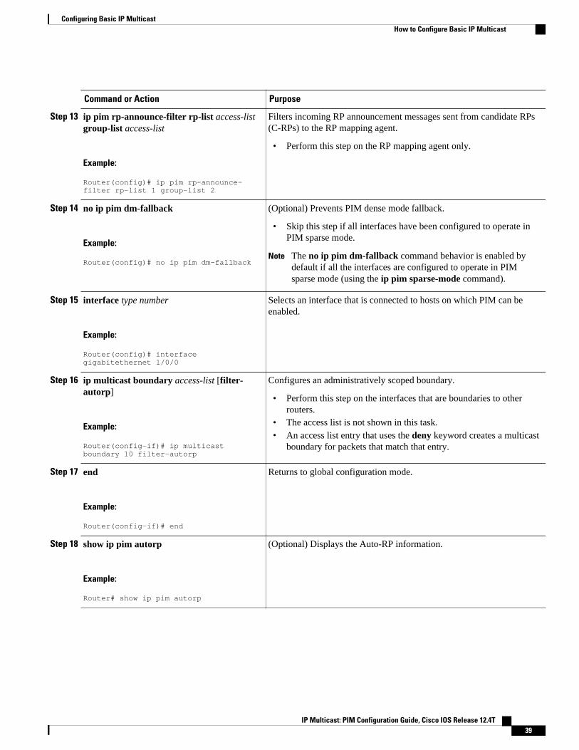
Command or Action Purpose
Step 13 ip pim rp-announce-filter rp-list access-listgroup-list access-list
Example:
Router(config)# ip pim rp-announce-filter rp-list 1 group-list 2
Filters incoming RP announcement messages sent from candidate RPs(C-RPs) to the RP mapping agent.
• Perform this step on the RP mapping agent only.
Step 14 no ip pim dm-fallback
Example:
Router(config)# no ip pim dm-fallback
(Optional) Prevents PIM dense mode fallback.
• Skip this step if all interfaces have been configured to operate inPIM sparse mode.
Note The no ip pim dm-fallback command behavior is enabled bydefault if all the interfaces are configured to operate in PIMsparse mode (using the ip pim sparse-mode command).
Step 15 interface type number
Example:
Router(config)# interface gigabitethernet 1/0/0
Selects an interface that is connected to hosts on which PIM can beenabled.
Step 16 ip multicast boundary access-list [filter-autorp]
Example:
Router(config-if)# ip multicast boundary 10 filter-autorp
Configures an administratively scoped boundary.
• Perform this step on the interfaces that are boundaries to otherrouters.
• The access list is not shown in this task.• An access list entry that uses the deny keyword creates a multicast
boundary for packets that match that entry.
Step 17 end
Example:
Router(config-if)# end
Returns to global configuration mode.
Step 18 show ip pim autorp
Example:
Router# show ip pim autorp
(Optional) Displays the Auto-RP information.
Configuring Basic IP MulticastHow to Configure Basic IP Multicast
IP Multicast: PIM Configuration Guide, Cisco IOS Release 12.4T 39
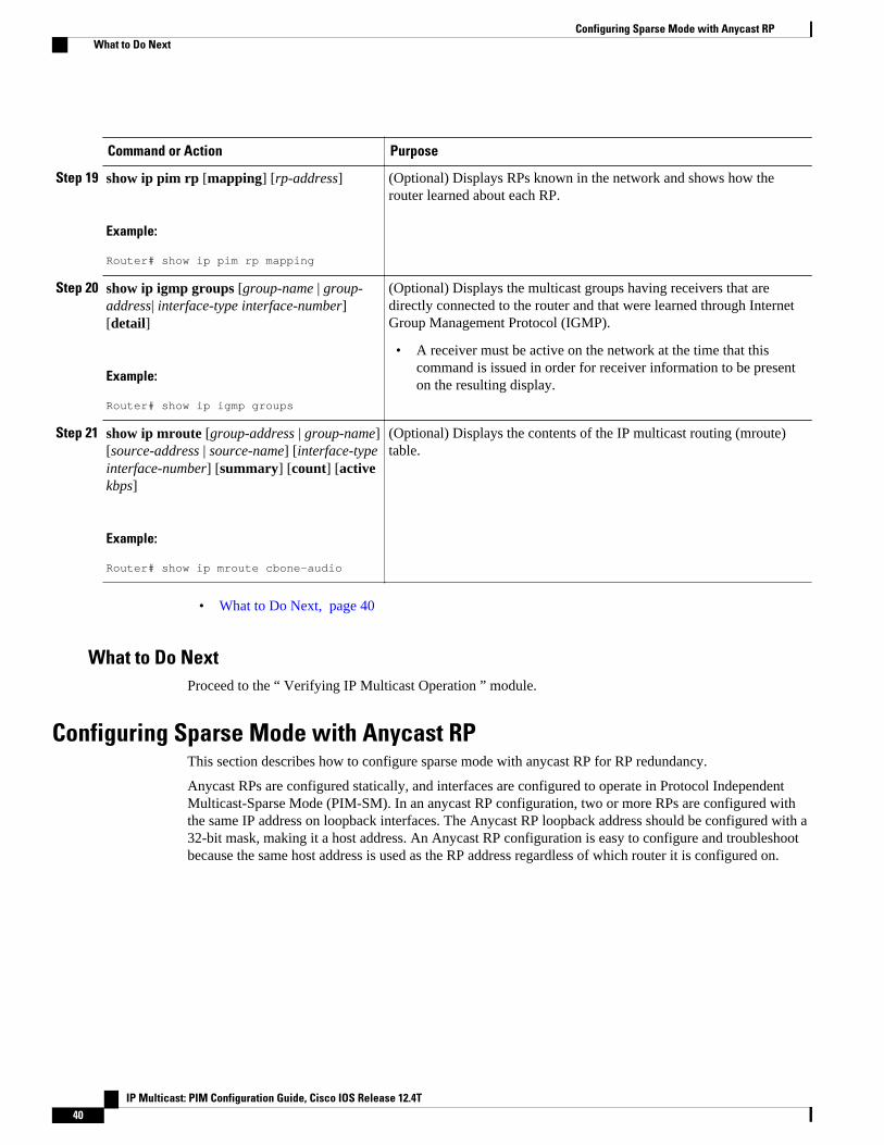
Command or Action Purpose
Step 19 show ip pim rp [mapping] [rp-address]
Example:
Router# show ip pim rp mapping
(Optional) Displays RPs known in the network and shows how therouter learned about each RP.
Step 20 show ip igmp groups [group-name | group-address| interface-type interface-number][detail]
Example:
Router# show ip igmp groups
(Optional) Displays the multicast groups having receivers that aredirectly connected to the router and that were learned through InternetGroup Management Protocol (IGMP).
• A receiver must be active on the network at the time that thiscommand is issued in order for receiver information to be presenton the resulting display.
Step 21 show ip mroute [group-address | group-name][source-address | source-name] [interface-typeinterface-number] [summary] [count] [activekbps]
Example:
Router# show ip mroute cbone-audio
(Optional) Displays the contents of the IP multicast routing (mroute)table.
• What to Do Next, page 40
What to Do NextProceed to the “ Verifying IP Multicast Operation ” module.
Configuring Sparse Mode with Anycast RPThis section describes how to configure sparse mode with anycast RP for RP redundancy.
Anycast RPs are configured statically, and interfaces are configured to operate in Protocol IndependentMulticast-Sparse Mode (PIM-SM). In an anycast RP configuration, two or more RPs are configured withthe same IP address on loopback interfaces. The Anycast RP loopback address should be configured with a32-bit mask, making it a host address. An Anycast RP configuration is easy to configure and troubleshootbecause the same host address is used as the RP address regardless of which router it is configured on.
Configuring Sparse Mode with Anycast RP What to Do Next
IP Multicast: PIM Configuration Guide, Cisco IOS Release 12.4T40
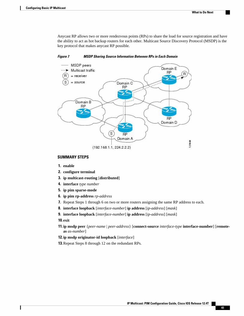
Anycast RP allows two or more rendezvous points (RPs) to share the load for source registration and havethe ability to act as hot backup routers for each other. Multicast Source Discovery Protocol (MSDP) is thekey protocol that makes anycast RP possible.
Figure 7 MSDP Sharing Source Information Between RPs in Each Domain
SUMMARY STEPS
1. enable
2. configure terminal
3. ip multicast-routing [distributed]
4. interface type number
5. ip pim sparse-mode
6. ip pim rp-address rp-address
7. Repeat Steps 1 through 6 on two or more routers assigning the same RP address to each.
8. interface loopback [interface-number] ip address [ip-address] [mask]
9. interface loopback [interface-number] ip address [ip-address] [mask]
10. exit
11. ip msdp peer {peer-name | peer-address} [connect-source interface-type interface-number] [remote-as as-number]
12. ip msdp originator-id loopback [interface]
13. Repeat Steps 8 through 12 on the redundant RPs.
Configuring Basic IP MulticastWhat to Do Next
IP Multicast: PIM Configuration Guide, Cisco IOS Release 12.4T 41

DETAILED STEPS
Command or Action Purpose
Step 1 enable
Example:
Router> enable
Enables privileged EXEC mode.
• Enter your password if prompted.
Step 2 configure terminal
Example:
Router# configure terminal
Enters global configuration mode.
Step 3 ip multicast-routing [distributed]
Example:
Router(config)# ip multicast-routing
Enables IP multicast routing.
• Use the distributed keyword to enableMulticast Distributed Switching.
Step 4 interface type number
Example:
Router(config)# interface gigabitethernet 1/0/0
Selects an interface that is connected to hosts onwhich PIM can be enabled.
Step 5 ip pim sparse-mode
Example:
Router(config-if)# ip pim sparse-mode
Enables sparse mode.
Step 6 ip pim rp-address rp-address
Example:
Router(config-if)# ip pim rp-address 10.0.0.1
Configures the address of a PIM RP for a particulargroup.
Step 7 Repeat Steps 1 through 6 on two or more routers assigning thesame RP address to each.
--
Configuring Basic IP Multicast What to Do Next
IP Multicast: PIM Configuration Guide, Cisco IOS Release 12.4T42
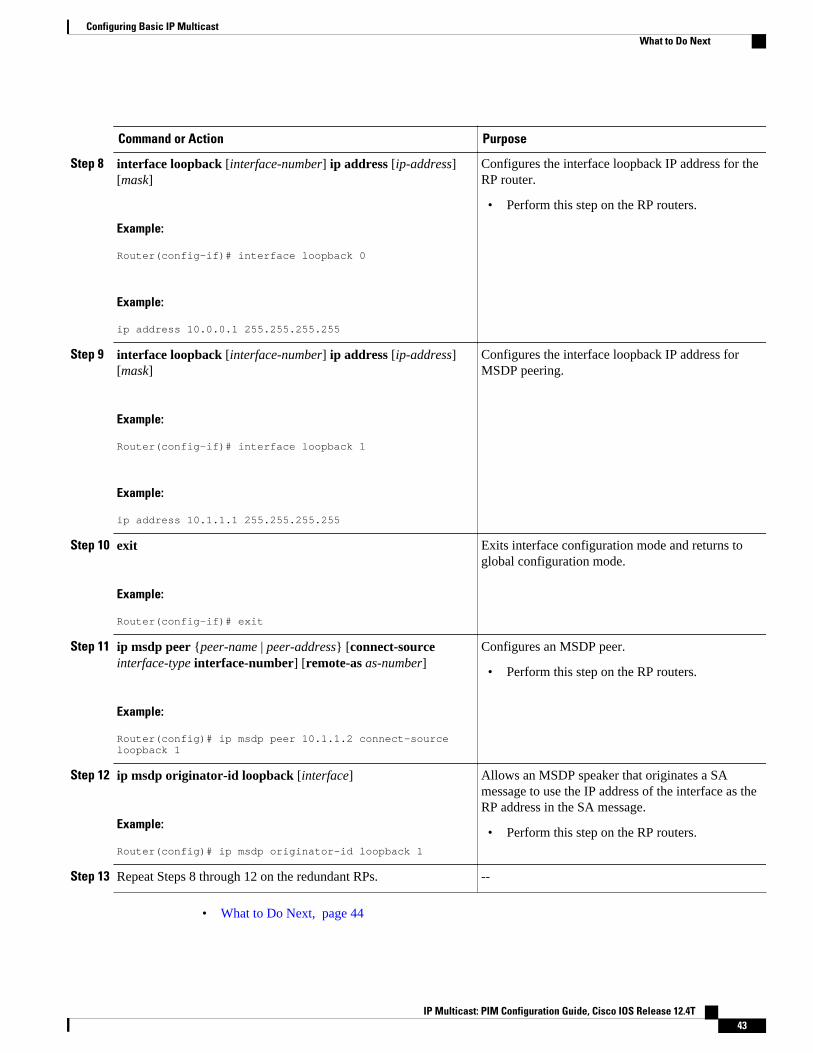
Command or Action Purpose
Step 8 interface loopback [interface-number] ip address [ip-address][mask]
Example:
Router(config-if)# interface loopback 0
Example:
ip address 10.0.0.1 255.255.255.255
Configures the interface loopback IP address for theRP router.
• Perform this step on the RP routers.
Step 9 interface loopback [interface-number] ip address [ip-address][mask]
Example:
Router(config-if)# interface loopback 1
Example:
ip address 10.1.1.1 255.255.255.255
Configures the interface loopback IP address forMSDP peering.
Step 10 exit
Example:
Router(config-if)# exit
Exits interface configuration mode and returns toglobal configuration mode.
Step 11 ip msdp peer {peer-name | peer-address} [connect-sourceinterface-type interface-number] [remote-as as-number]
Example:
Router(config)# ip msdp peer 10.1.1.2 connect-source loopback 1
Configures an MSDP peer.
• Perform this step on the RP routers.
Step 12 ip msdp originator-id loopback [interface]
Example:
Router(config)# ip msdp originator-id loopback 1
Allows an MSDP speaker that originates a SAmessage to use the IP address of the interface as theRP address in the SA message.
• Perform this step on the RP routers.
Step 13 Repeat Steps 8 through 12 on the redundant RPs. --
• What to Do Next, page 44
Configuring Basic IP MulticastWhat to Do Next
IP Multicast: PIM Configuration Guide, Cisco IOS Release 12.4T 43
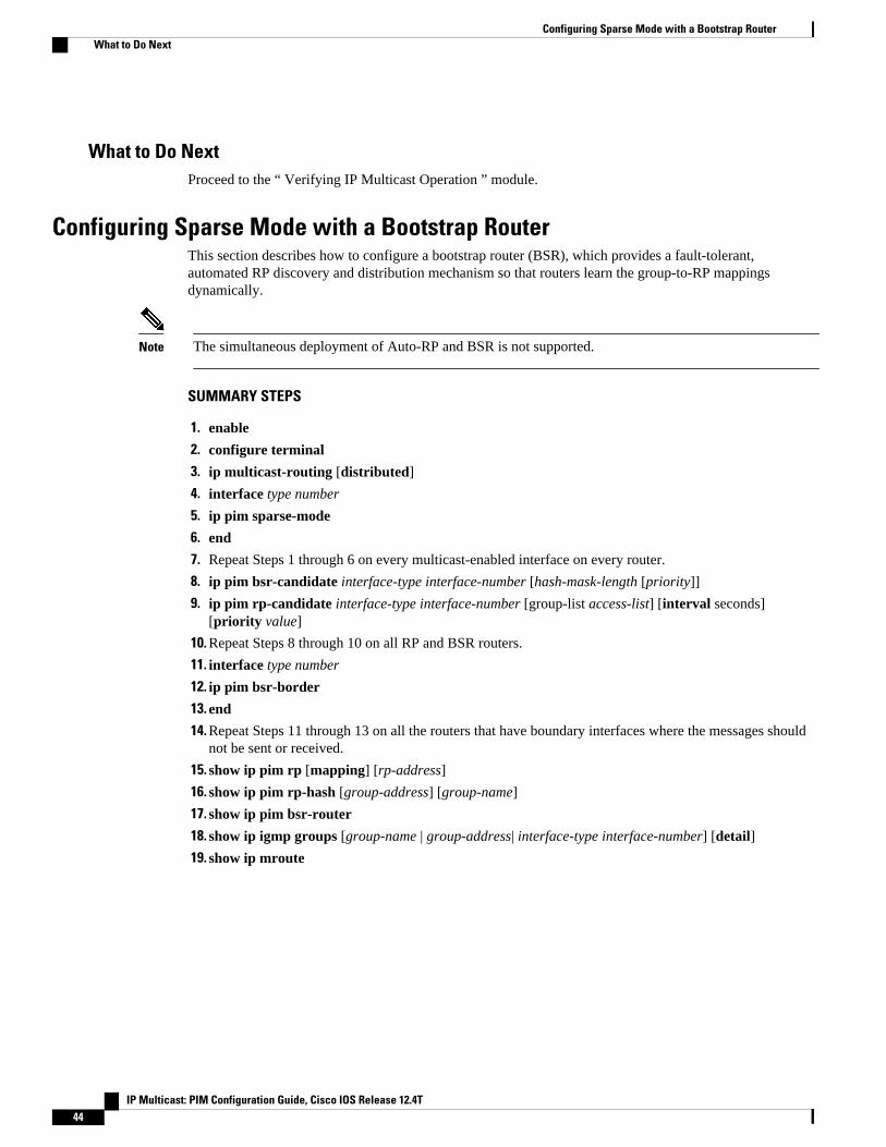
What to Do NextProceed to the “ Verifying IP Multicast Operation ” module.
Configuring Sparse Mode with a Bootstrap RouterThis section describes how to configure a bootstrap router (BSR), which provides a fault-tolerant,automated RP discovery and distribution mechanism so that routers learn the group-to-RP mappingsdynamically.
Note The simultaneous deployment of Auto-RP and BSR is not supported.
SUMMARY STEPS
1. enable
2. configure terminal
3. ip multicast-routing [distributed]
4. interface type number
5. ip pim sparse-mode
6. end
7. Repeat Steps 1 through 6 on every multicast-enabled interface on every router.
8. ip pim bsr-candidate interface-type interface-number [hash-mask-length [priority]]
9. ip pim rp-candidate interface-type interface-number [group-list access-list] [interval seconds][priority value]
10. Repeat Steps 8 through 10 on all RP and BSR routers.
11. interface type number
12. ip pim bsr-border
13. end
14. Repeat Steps 11 through 13 on all the routers that have boundary interfaces where the messages shouldnot be sent or received.
15. show ip pim rp [mapping] [rp-address]
16. show ip pim rp-hash [group-address] [group-name]
17. show ip pim bsr-router
18. show ip igmp groups [group-name | group-address| interface-type interface-number] [detail]
19. show ip mroute
Configuring Sparse Mode with a Bootstrap Router What to Do Next
IP Multicast: PIM Configuration Guide, Cisco IOS Release 12.4T44
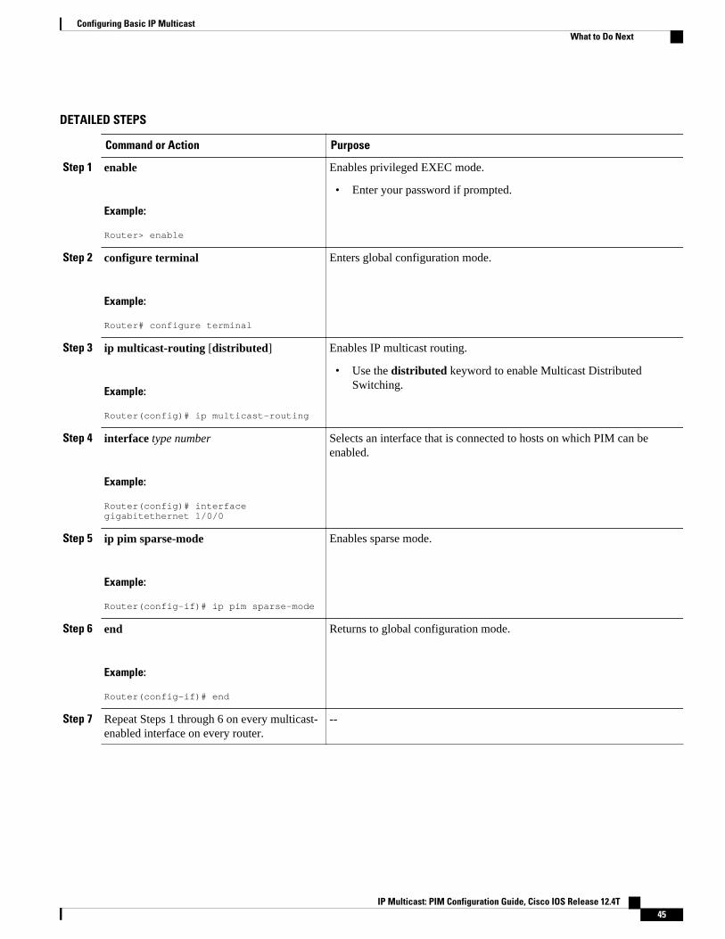
DETAILED STEPS
Command or Action Purpose
Step 1 enable
Example:
Router> enable
Enables privileged EXEC mode.
• Enter your password if prompted.
Step 2 configure terminal
Example:
Router# configure terminal
Enters global configuration mode.
Step 3 ip multicast-routing [distributed]
Example:
Router(config)# ip multicast-routing
Enables IP multicast routing.
• Use the distributed keyword to enable Multicast DistributedSwitching.
Step 4 interface type number
Example:
Router(config)# interface gigabitethernet 1/0/0
Selects an interface that is connected to hosts on which PIM can beenabled.
Step 5 ip pim sparse-mode
Example:
Router(config-if)# ip pim sparse-mode
Enables sparse mode.
Step 6 end
Example:
Router(config-if)# end
Returns to global configuration mode.
Step 7 Repeat Steps 1 through 6 on every multicast-enabled interface on every router.
--
Configuring Basic IP MulticastWhat to Do Next
IP Multicast: PIM Configuration Guide, Cisco IOS Release 12.4T 45
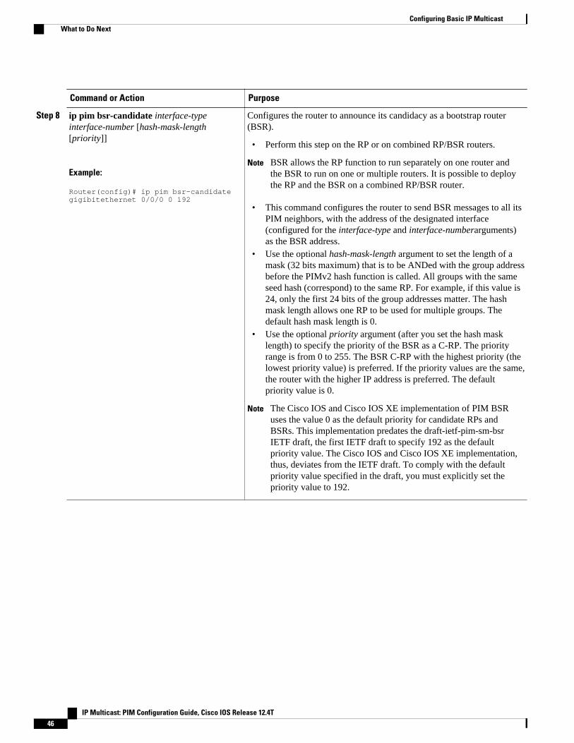
Command or Action Purpose
Step 8 ip pim bsr-candidate interface-typeinterface-number [hash-mask-length[priority]]
Example:
Router(config)# ip pim bsr-candidate gigibitethernet 0/0/0 0 192
Configures the router to announce its candidacy as a bootstrap router(BSR).
• Perform this step on the RP or on combined RP/BSR routers.
Note BSR allows the RP function to run separately on one router andthe BSR to run on one or multiple routers. It is possible to deploythe RP and the BSR on a combined RP/BSR router.
• This command configures the router to send BSR messages to all itsPIM neighbors, with the address of the designated interface(configured for the interface-type and interface-numberarguments)as the BSR address.
• Use the optional hash-mask-length argument to set the length of amask (32 bits maximum) that is to be ANDed with the group addressbefore the PIMv2 hash function is called. All groups with the sameseed hash (correspond) to the same RP. For example, if this value is24, only the first 24 bits of the group addresses matter. The hashmask length allows one RP to be used for multiple groups. Thedefault hash mask length is 0.
• Use the optional priority argument (after you set the hash masklength) to specify the priority of the BSR as a C-RP. The priorityrange is from 0 to 255. The BSR C-RP with the highest priority (thelowest priority value) is preferred. If the priority values are the same,the router with the higher IP address is preferred. The defaultpriority value is 0.
Note The Cisco IOS and Cisco IOS XE implementation of PIM BSRuses the value 0 as the default priority for candidate RPs andBSRs. This implementation predates the draft-ietf-pim-sm-bsrIETF draft, the first IETF draft to specify 192 as the defaultpriority value. The Cisco IOS and Cisco IOS XE implementation,thus, deviates from the IETF draft. To comply with the defaultpriority value specified in the draft, you must explicitly set thepriority value to 192.
Configuring Basic IP Multicast What to Do Next
IP Multicast: PIM Configuration Guide, Cisco IOS Release 12.4T46
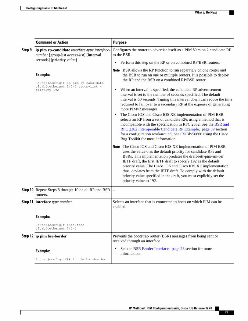
Command or Action Purpose
Step 9 ip pim rp-candidate interface-type interface-number [group-list access-list] [intervalseconds] [priority value]
Example:
Router(config)# ip pim rp-candidate gigabitethernet 2/0/0 group-list 4 priority 192
Configures the router to advertise itself as a PIM Version 2 candidate RPto the BSR.
• Perform this step on the RP or on combined RP/BSR routers.
Note BSR allows the RP function to run separately on one router andthe BSR to run on one or multiple routers. It is possible to deploythe RP and the BSR on a combined RP/BSR router.
• When an interval is specified, the candidate RP advertisementinterval is set to the number of seconds specified. The defaultinterval is 60 seconds. Tuning this interval down can reduce the timerequired to fail over to a secondary RP at the expense of generatingmore PIMv2 messages.
• The Cisco IOS and Cisco IOS XE implementation of PIM BSRselects an RP from a set of candidate RPs using a method that isincompatible with the specification in RFC 2362. See the BSR andRFC 2362 Interoperable Candidate RP Example, page 59 sectionfor a configuration workaround. See CSCdy56806 using the CiscoBug Toolkit for more information.
Note The Cisco IOS and Cisco IOS XE implementation of PIM BSRuses the value 0 as the default priority for candidate RPs andBSRs. This implementation predates the draft-ietf-pim-sm-bsrIETF draft, the first IETF draft to specify 192 as the defaultpriority value. The Cisco IOS and Cisco IOS XE implementation,thus, deviates from the IETF draft. To comply with the defaultpriority value specified in the draft, you must explicitly set thepriority value to 192.
Step 10 Repeat Steps 8 through 10 on all RP and BSRrouters.
--
Step 11 interface type number
Example:
Router(config)# interface gigabitethernet 1/0/0
Selects an interface that is connected to hosts on which PIM can beenabled.
Step 12 ip pim bsr-border
Example:
Router(config-if)# ip pim bsr-border
Prevents the bootstrap router (BSR) messages from being sent orreceived through an interface.
• See the BSR Border Interface, page 28 section for moreinformation.
Configuring Basic IP MulticastWhat to Do Next
IP Multicast: PIM Configuration Guide, Cisco IOS Release 12.4T 47

Command or Action Purpose
Step 13 end
Example:
Router(config-if)# end
Ends the current configuration session and returns to privileged EXECmode.
Step 14 Repeat Steps 11 through 13 on all the routersthat have boundary interfaces where themessages should not be sent or received.
--
Step 15 show ip pim rp [mapping] [rp-address]
Example:
Router# show ip pim rp
(Optional) Displays active rendezvous points (RPs) that are cached withassociated multicast routing entries.
Step 16 show ip pim rp-hash [group-address][group-name]
Example:
Router# show ip pim rp-hash 239.1.1.1
(Optional) Displays which rendezvous point (RP) is being selected for aspecified group.
Step 17 show ip pim bsr-router
Example:
Router# show ip pim bsr-router
(Optional) Displays the bootstrap router (BSR) information.
Step 18 show ip igmp groups [group-name | group-address| interface-type interface-number][detail]
Example:
Router# show ip igmp groups
(Optional) Displays the multicast groups having receivers that aredirectly connected to the router and that were learned through IGMP.
• A receiver must be active on the network at the time that thiscommand is issued in order for receiver information to be present onthe resulting display.
Step 19 show ip mroute
Example:
Router# show ip mroute cbone-audio
(Optional) Displays the contents of the IP mroute table.
• What to Do Next, page 40
Configuring Basic IP Multicast What to Do Next
IP Multicast: PIM Configuration Guide, Cisco IOS Release 12.4T48
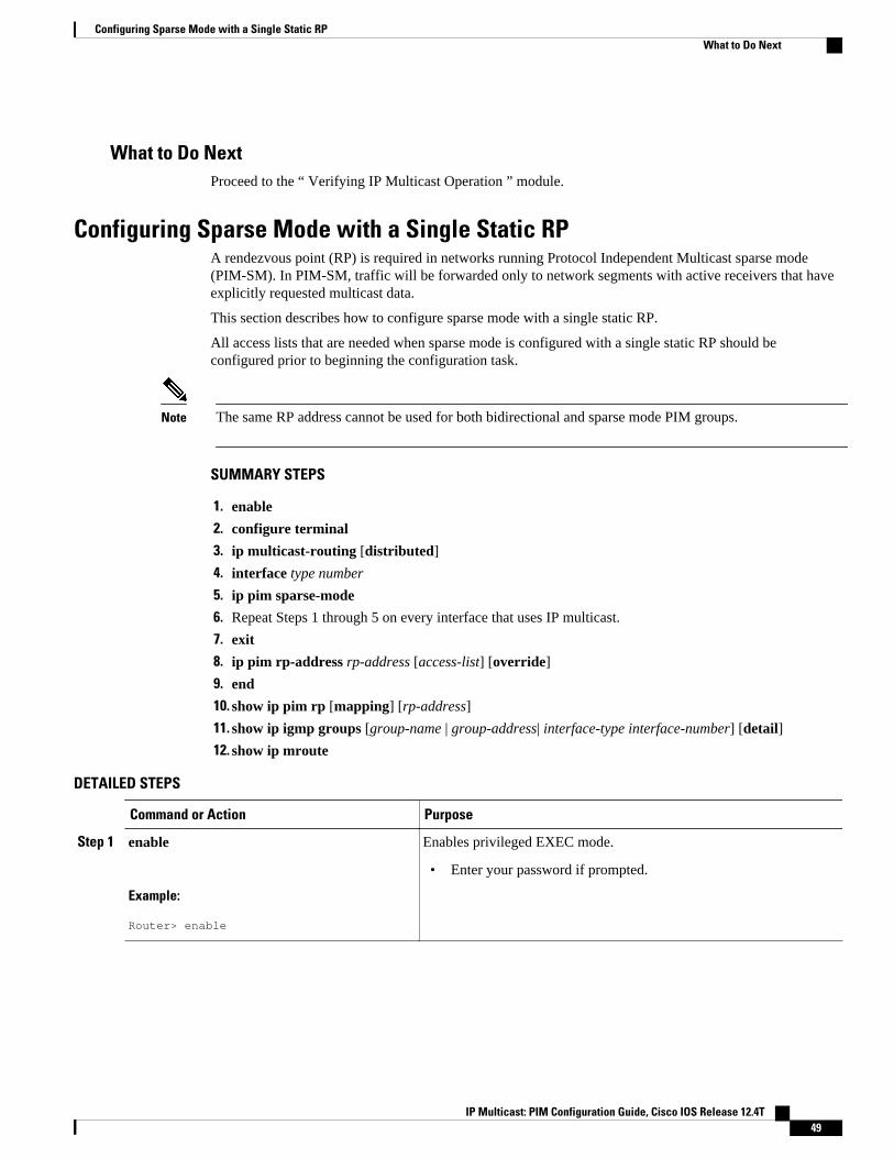
What to Do NextProceed to the “ Verifying IP Multicast Operation ” module.
Configuring Sparse Mode with a Single Static RPA rendezvous point (RP) is required in networks running Protocol Independent Multicast sparse mode(PIM-SM). In PIM-SM, traffic will be forwarded only to network segments with active receivers that haveexplicitly requested multicast data.
This section describes how to configure sparse mode with a single static RP.
All access lists that are needed when sparse mode is configured with a single static RP should beconfigured prior to beginning the configuration task.
Note The same RP address cannot be used for both bidirectional and sparse mode PIM groups.
SUMMARY STEPS
1. enable
2. configure terminal
3. ip multicast-routing [distributed]
4. interface type number
5. ip pim sparse-mode
6. Repeat Steps 1 through 5 on every interface that uses IP multicast.
7. exit
8. ip pim rp-address rp-address [access-list] [override]
9. end
10. show ip pim rp [mapping] [rp-address]
11. show ip igmp groups [group-name | group-address| interface-type interface-number] [detail]
12. show ip mroute
DETAILED STEPS
Command or Action Purpose
Step 1 enable
Example:
Router> enable
Enables privileged EXEC mode.
• Enter your password if prompted.
Configuring Sparse Mode with a Single Static RPWhat to Do Next
IP Multicast: PIM Configuration Guide, Cisco IOS Release 12.4T 49

Command or Action Purpose
Step 2 configure terminal
Example:
Router# configure terminal
Enters global configuration mode.
Step 3 ip multicast-routing [distributed]
Example:
Router(config)# ip multicast-routing
Enables IP multicast routing.
• Use the distributed keyword to enable Multicast DistributedSwitching.
Step 4 interface type number
Example:
Router(config)# interface gigabitethernet 1/0/0
Selects an interface that is connected to hosts on which PIM can beenabled.
Step 5 ip pim sparse-mode
Example:
Router(config-if)# ip pim sparse-mode
Enables PIM on an interface. You must use sparse mode.
Step 6 Repeat Steps 1 through 5 on every interface thatuses IP multicast.
--
Step 7 exit
Example:
Router(config-if)# exit
Returns to global configuration mode.
Configuring Basic IP Multicast What to Do Next
IP Multicast: PIM Configuration Guide, Cisco IOS Release 12.4T50
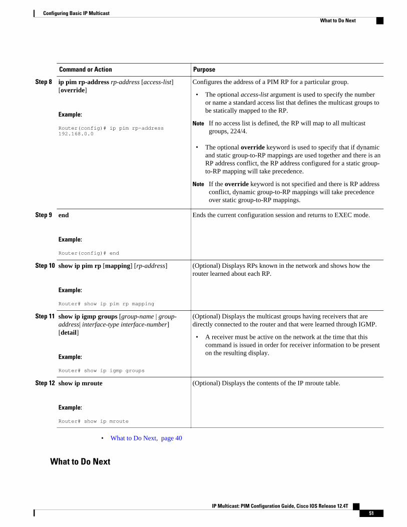
Command or Action Purpose
Step 8 ip pim rp-address rp-address [access-list][override]
Example:
Router(config)# ip pim rp-address 192.168.0.0
Configures the address of a PIM RP for a particular group.
• The optional access-list argument is used to specify the numberor name a standard access list that defines the multicast groups tobe statically mapped to the RP.
Note If no access list is defined, the RP will map to all multicastgroups, 224/4.
• The optional override keyword is used to specify that if dynamicand static group-to-RP mappings are used together and there is anRP address conflict, the RP address configured for a static group-to-RP mapping will take precedence.
Note If the override keyword is not specified and there is RP addressconflict, dynamic group-to-RP mappings will take precedenceover static group-to-RP mappings.
Step 9 end
Example:
Router(config)# end
Ends the current configuration session and returns to EXEC mode.
Step 10 show ip pim rp [mapping] [rp-address]
Example:
Router# show ip pim rp mapping
(Optional) Displays RPs known in the network and shows how therouter learned about each RP.
Step 11 show ip igmp groups [group-name | group-address| interface-type interface-number][detail]
Example:
Router# show ip igmp groups
(Optional) Displays the multicast groups having receivers that aredirectly connected to the router and that were learned through IGMP.
• A receiver must be active on the network at the time that thiscommand is issued in order for receiver information to be presenton the resulting display.
Step 12 show ip mroute
Example:
Router# show ip mroute
(Optional) Displays the contents of the IP mroute table.
• What to Do Next, page 40
What to Do Next
Configuring Basic IP MulticastWhat to Do Next
IP Multicast: PIM Configuration Guide, Cisco IOS Release 12.4T 51
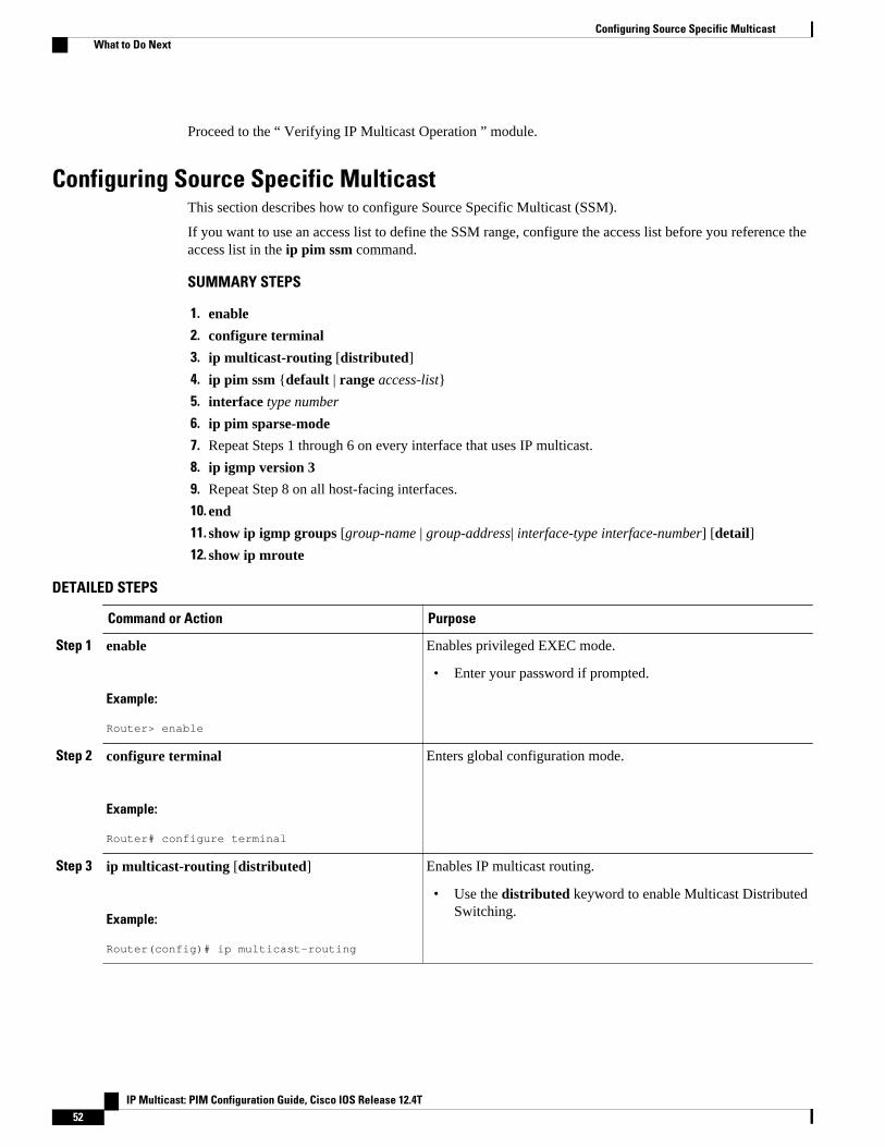
Proceed to the “ Verifying IP Multicast Operation ” module.
Configuring Source Specific MulticastThis section describes how to configure Source Specific Multicast (SSM).
If you want to use an access list to define the SSM range, configure the access list before you reference theaccess list in the ip pim ssm command.
SUMMARY STEPS
1. enable
2. configure terminal
3. ip multicast-routing [distributed]
4. ip pim ssm {default | range access-list}
5. interface type number
6. ip pim sparse-mode
7. Repeat Steps 1 through 6 on every interface that uses IP multicast.
8. ip igmp version 3
9. Repeat Step 8 on all host-facing interfaces.
10. end
11. show ip igmp groups [group-name | group-address| interface-type interface-number] [detail]
12. show ip mroute
DETAILED STEPS
Command or Action Purpose
Step 1 enable
Example:
Router> enable
Enables privileged EXEC mode.
• Enter your password if prompted.
Step 2 configure terminal
Example:
Router# configure terminal
Enters global configuration mode.
Step 3 ip multicast-routing [distributed]
Example:
Router(config)# ip multicast-routing
Enables IP multicast routing.
• Use the distributed keyword to enable Multicast DistributedSwitching.
Configuring Source Specific Multicast What to Do Next
IP Multicast: PIM Configuration Guide, Cisco IOS Release 12.4T52
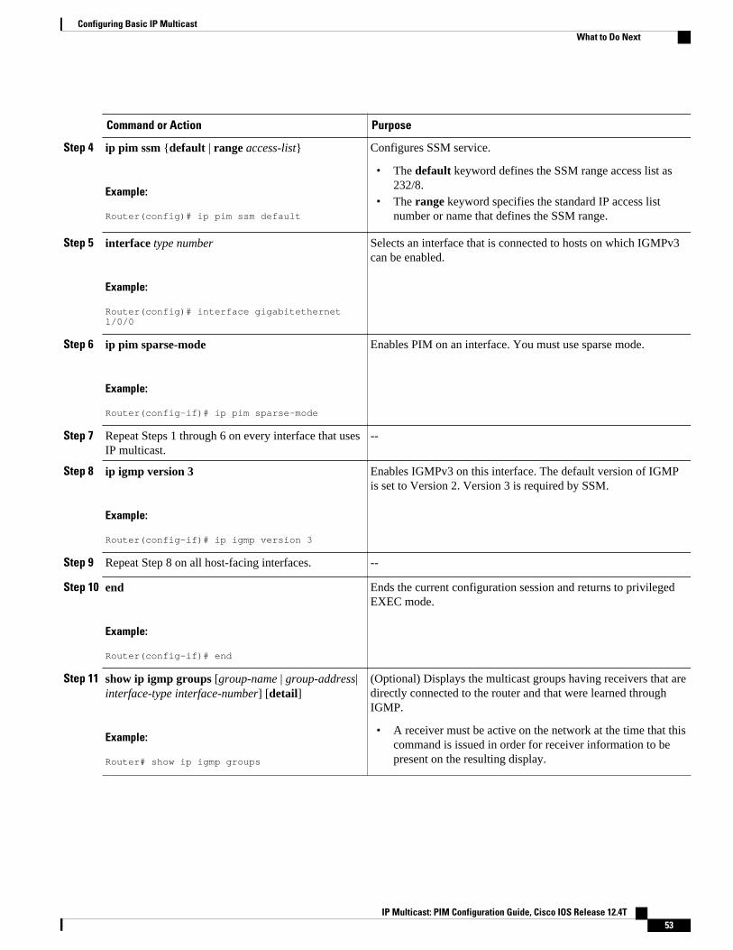
Command or Action Purpose
Step 4 ip pim ssm {default | range access-list}
Example:
Router(config)# ip pim ssm default
Configures SSM service.
• The default keyword defines the SSM range access list as232/8.
• The range keyword specifies the standard IP access listnumber or name that defines the SSM range.
Step 5 interface type number
Example:
Router(config)# interface gigabitethernet 1/0/0
Selects an interface that is connected to hosts on which IGMPv3can be enabled.
Step 6 ip pim sparse-mode
Example:
Router(config-if)# ip pim sparse-mode
Enables PIM on an interface. You must use sparse mode.
Step 7 Repeat Steps 1 through 6 on every interface that usesIP multicast.
--
Step 8 ip igmp version 3
Example:
Router(config-if)# ip igmp version 3
Enables IGMPv3 on this interface. The default version of IGMPis set to Version 2. Version 3 is required by SSM.
Step 9 Repeat Step 8 on all host-facing interfaces. --
Step 10 end
Example:
Router(config-if)# end
Ends the current configuration session and returns to privilegedEXEC mode.
Step 11 show ip igmp groups [group-name | group-address|interface-type interface-number] [detail]
Example:
Router# show ip igmp groups
(Optional) Displays the multicast groups having receivers that aredirectly connected to the router and that were learned throughIGMP.
• A receiver must be active on the network at the time that thiscommand is issued in order for receiver information to bepresent on the resulting display.
Configuring Basic IP MulticastWhat to Do Next
IP Multicast: PIM Configuration Guide, Cisco IOS Release 12.4T 53

Command or Action Purpose
Step 12 show ip mroute
Example:
Router# show ip mroute
(Optional) Displays the contents of the IP mroute table.
• This command displays whether a multicast group isconfigured for SSM service or a source-specific host reporthas been received.
• What to Do Next, page 40
What to Do NextProceed to the “ Verifying IP Multicast Operation ” module.
Configuring Bidirectional PIMThis section describes how to configure bidirectional PIM (bidir-PIM).
All access lists needed when configuring bidirectional PIM must be configured prior to beginning theconfiguration task.
SUMMARY STEPS
1. enable
2. configure terminal
3. ip multicast-routing [distributed]
4. interface type number
5. ip pim sparse-mode
6. exit
7. ip pim bidir-enable
8. ip pim rp-address rp-address [access-list] [override] bidir
9. end
10. Repeat Steps 2 through 9 on every multicast-enabled interface on every router.
11. show ip pim rp [mapping] [rp-address]
12. show ip mroute
13. show ip pim interface [type number] [df | count] [rp-address]
DETAILED STEPS
Command or Action Purpose
Step 1 enable
Example:
Router> enable
Enables privileged EXEC mode.
• Enter your password if prompted.
Configuring Bidirectional PIM What to Do Next
IP Multicast: PIM Configuration Guide, Cisco IOS Release 12.4T54
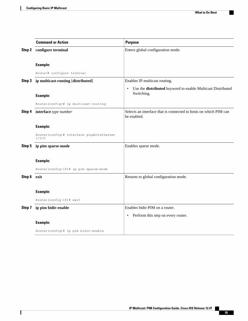
Command or Action Purpose
Step 2 configure terminal
Example:
Router# configure terminal
Enters global configuration mode.
Step 3 ip multicast-routing [distributed]
Example:
Router(config)# ip multicast-routing
Enables IP multicast routing.
• Use the distributed keyword to enable Multicast DistributedSwitching.
Step 4 interface type number
Example:
Router(config)# interface gigabitethernet 1/0/0
Selects an interface that is connected to hosts on which PIM canbe enabled.
Step 5 ip pim sparse-mode
Example:
Router(config-if)# ip pim sparse-mode
Enables sparse mode.
Step 6 exit
Example:
Router(config-if)# exit
Returns to global configuration mode.
Step 7 ip pim bidir-enable
Example:
Router(config)# ip pim bidir-enable
Enables bidir-PIM on a router.
• Perform this step on every router.
Configuring Basic IP MulticastWhat to Do Next
IP Multicast: PIM Configuration Guide, Cisco IOS Release 12.4T 55
Command or Action Purpose
Step 8 ip pim rp-address rp-address [access-list][override] bidir
Example:
Router(config)# ip pim rp-address 10.0.1.1 45 bidir
Configures the address of a PIM RP for a particular group.
• Perform this step on every router.• This command defines the RP as bidirectional and defines
the bidirectional group by way of the access list.• The optional override keyword is used to specify that if
dynamic and static group-to-RP mappings are used togetherand there is an RP address conflict, the RP addressconfigured for a static group-to-RP mapping will takeprecedence.
Note If the override keyword is not specified and there is RPaddress conflict, dynamic group-to-RP mappings will takeprecedence over static group-to-RP mappings.
Step 9 end
Example:
Router(config-if)# end
Exits interface configuration mode and returns to privilegedEXEC mode.
Step 10 Repeat Steps 2 through 9 on every multicast-enabledinterface on every router.
--
Step 11 show ip pim rp [mapping] [rp-address]
Example:
Router# show ip pim rp
(Optional) Displays active RPs that are cached with associatedmulticast routing entries.
Step 12 show ip mroute
Example:
Router# show ip mroute
(Optional) Displays the contents of the IP mroute table.
Step 13 show ip pim interface [type number] [df | count][rp-address]
Example:
Router# show ip pim interface
(Optional) Displays information about the elected DF for each RPof an interface, along with the unicast routing metric associatedwith the DF.
Configuration Examples for Basic IP Multicast• Sparse Mode with Auto-RP Example, page 57
Configuring Basic IP Multicast Configuration Examples for Basic IP Multicast
IP Multicast: PIM Configuration Guide, Cisco IOS Release 12.4T56
• Sparse Mode with Anycast RP Example, page 57
• Sparse Mode with Bootstrap Router Example, page 59
• BSR and RFC 2362 Interoperable Candidate RP Example, page 59
• Sparse Mode with a Single Static RP Example, page 60
• SSM with IGMPv3 Example, page 60
• SSM Filtering Example, page 61
• Bidir-PIM Example, page 61
Sparse Mode with Auto-RP ExampleThe following example configures sparse mode with Auto-RP:
ip multicast-routing ip pim autorp listener ip pim send-rp-announce Loopback0 scope 16 group-list 1 ip pim send-rp-discovery Loopback1 scope 16 no ip pim dm-fallbackaccess-list 1 permit 239.254.2.0 0.0.0.255 access-list 1 permit 239.254.3.0 0.0.0.255...access-list 10 permit 224.0.1.39access-list 10 permit 224.0.1.40access-list 10 permit 239.254.2.0 0.0.0.255access-list 10 permit 239.254.3.0 0.0.0.255
Sparse Mode with Anycast RP ExampleThe main purpose of an Anycast RP implementation is that the downstream multicast routers will have justone address for an RP. The example given in the figure below shows how loopback interface 0 of the RPs(RP1 and RP2) is configured with the 10.0.0.1 IP address. If this 10.0.0.1 address is configured on all RPsas the address for loopback interface 0 and then configured as the RP address, IP routing will converge onthe closest RP. This address must be a host route; note the 255.255.255.255 subnet mask.
The downstream routers must be informed about the 10.0.0.1 RP address. In the figure below, the routersare configured statically with the ip pim rp-address 10.0.0.1global configuration command. Thisconfiguration could also be accomplished using the Auto-RP or bootstrap router (BSR) features.
Sparse Mode with Auto-RP ExampleConfiguration Examples for Basic IP Multicast
IP Multicast: PIM Configuration Guide, Cisco IOS Release 12.4T 57
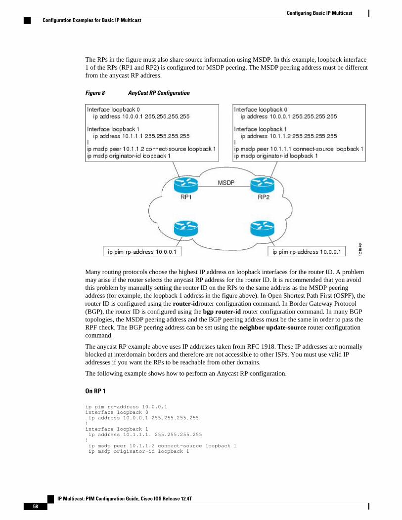
The RPs in the figure must also share source information using MSDP. In this example, loopback interface1 of the RPs (RP1 and RP2) is configured for MSDP peering. The MSDP peering address must be differentfrom the anycast RP address.
Figure 8 AnyCast RP Configuration
Many routing protocols choose the highest IP address on loopback interfaces for the router ID. A problemmay arise if the router selects the anycast RP address for the router ID. It is recommended that you avoidthis problem by manually setting the router ID on the RPs to the same address as the MSDP peeringaddress (for example, the loopback 1 address in the figure above). In Open Shortest Path First (OSPF), therouter ID is configured using the router-idrouter configuration command. In Border Gateway Protocol(BGP), the router ID is configured using the bgp router-id router configuration command. In many BGPtopologies, the MSDP peering address and the BGP peering address must be the same in order to pass theRPF check. The BGP peering address can be set using the neighbor update-source router configurationcommand.
The anycast RP example above uses IP addresses taken from RFC 1918. These IP addresses are normallyblocked at interdomain borders and therefore are not accessible to other ISPs. You must use valid IPaddresses if you want the RPs to be reachable from other domains.
The following example shows how to perform an Anycast RP configuration.
On RP 1
ip pim rp-address 10.0.0.1interface loopback 0 ip address 10.0.0.1 255.255.255.255!interface loopback 1 ip address 10.1.1.1. 255.255.255.255! ip msdp peer 10.1.1.2 connect-source loopback 1 ip msdp originator-id loopback 1
Configuring Basic IP Multicast Configuration Examples for Basic IP Multicast
IP Multicast: PIM Configuration Guide, Cisco IOS Release 12.4T58
On RP 2
ip pim rp-address 10.0.0.1interface loopback 0 ip address 10.0.0.1 255.255.255.255interface loopback 1 ip address 10.1.1.2. 255.255.255.255! ip msdp peer 10.1.1.1 connect-source loopback 1 ip msdp originator-id loopback 1
All Other Routers
ip pim rp-address 10.0.0.1
Sparse Mode with Bootstrap Router ExampleThe following example is a configuration for a candidate BSR, which also happens to be a candidate RP:
! ip multicast-routing ! interface GigabitEthernet0/0/0 ip address 172.69.62.35 255.255.255.240 ip pim sparse-mode ! interface GigabitEthernet1/0/0 ip address 172.21.24.18 255.255.255.248 ip pim sparse-mode ! interface GigabitEthernet2/0/0 ip address 172.21.24.12 255.255.255.248 ip pim sparse-mode ! ip pim bsr-candidate GigabitEthernet2/0/0 30 10 ip pim rp-candidate GigabitEthernet2/0/0 group-list 5 access-list 5 permit 239.255.2.0 0.0.0.255
BSR and RFC 2362 Interoperable Candidate RP ExampleWhen Cisco and non-Cisco routers are being operated in a single PIM domain with PIM Version 2 BSR,care must be taken when configuring candidate RPs because the Cisco implementation of the BSR RPselection is not fully compatible with RFC 2362.
RFC 2362 specifies that the BSR RP be selected as follows (RFC 2362, 3.7):
1 Select the candidate RP with the highest priority (lowest configured priority value).2 If there is a tie in the priority level, select the candidate RP with the highest hash function value.3 If there is a tie in the hash function value, select the candidate RP with the highest IP address.
Cisco routers always select the candidate RP based on the longest match on the announced group addressprefix before selecting an RP based on priority, hash function, or IP address.
Inconsistent candidate RP selection between Cisco and non-Cisco RFC 2362-compliant routers in the samedomain if multiple candidate RPs with partially overlapping group address ranges are configured can occur.Inconsistent candidate RP selection can prevent connectivity between sources and receivers in the PIMdomain. A source may register with one candidate RP and a receiver may connect to a different candidateRP even though it is in the same group.
Sparse Mode with Bootstrap Router ExampleConfiguration Examples for Basic IP Multicast
IP Multicast: PIM Configuration Guide, Cisco IOS Release 12.4T 59
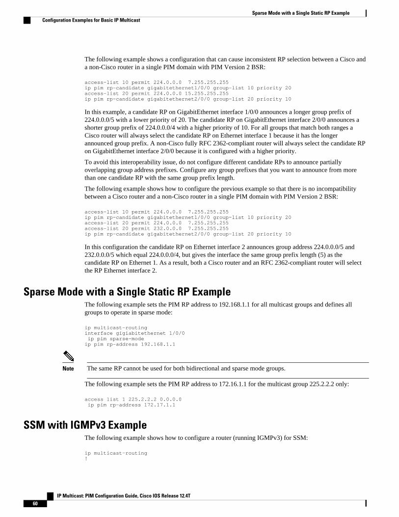
The following example shows a configuration that can cause inconsistent RP selection between a Cisco anda non-Cisco router in a single PIM domain with PIM Version 2 BSR:
access-list 10 permit 224.0.0.0 7.255.255.255 ip pim rp-candidate gigabitethernet1/0/0 group-list 10 priority 20access-list 20 permit 224.0.0.0 15.255.255.255ip pim rp-candidate gigabitethernet2/0/0 group-list 20 priority 10
In this example, a candidate RP on GigabitEthernet interface 1/0/0 announces a longer group prefix of224.0.0.0/5 with a lower priority of 20. The candidate RP on GigabitEthernet interface 2/0/0 announces ashorter group prefix of 224.0.0.0/4 with a higher priority of 10. For all groups that match both ranges aCisco router will always select the candidate RP on Ethernet interface 1 because it has the longerannounced group prefix. A non-Cisco fully RFC 2362-compliant router will always select the candidate RPon GigabitEthernet interface 2/0/0 because it is configured with a higher priority.
To avoid this interoperability issue, do not configure different candidate RPs to announce partiallyoverlapping group address prefixes. Configure any group prefixes that you want to announce from morethan one candidate RP with the same group prefix length.
The following example shows how to configure the previous example so that there is no incompatibilitybetween a Cisco router and a non-Cisco router in a single PIM domain with PIM Version 2 BSR:
access-list 10 permit 224.0.0.0 7.255.255.255 ip pim rp-candidate gigabitethernet1/0/0 group-list 10 priority 20access-list 20 permit 224.0.0.0 7.255.255.255access-list 20 permit 232.0.0.0 7.255.255.255ip pim rp-candidate gigabitethernet2/0/0 group-list 20 priority 10
In this configuration the candidate RP on Ethernet interface 2 announces group address 224.0.0.0/5 and232.0.0.0/5 which equal 224.0.0.0/4, but gives the interface the same group prefix length (5) as thecandidate RP on Ethernet 1. As a result, both a Cisco router and an RFC 2362-compliant router will selectthe RP Ethernet interface 2.
Sparse Mode with a Single Static RP ExampleThe following example sets the PIM RP address to 192.168.1.1 for all multicast groups and defines allgroups to operate in sparse mode:
ip multicast-routinginterface gigiabitethernet 1/0/0 ip pim sparse-modeip pim rp-address 192.168.1.1
Note The same RP cannot be used for both bidirectional and sparse mode groups.
The following example sets the PIM RP address to 172.16.1.1 for the multicast group 225.2.2.2 only:
access list 1 225.2.2.2 0.0.0.0 ip pim rp-address 172.17.1.1
SSM with IGMPv3 ExampleThe following example shows how to configure a router (running IGMPv3) for SSM:
ip multicast-routing !
Sparse Mode with a Single Static RP Example Configuration Examples for Basic IP Multicast
IP Multicast: PIM Configuration Guide, Cisco IOS Release 12.4T60
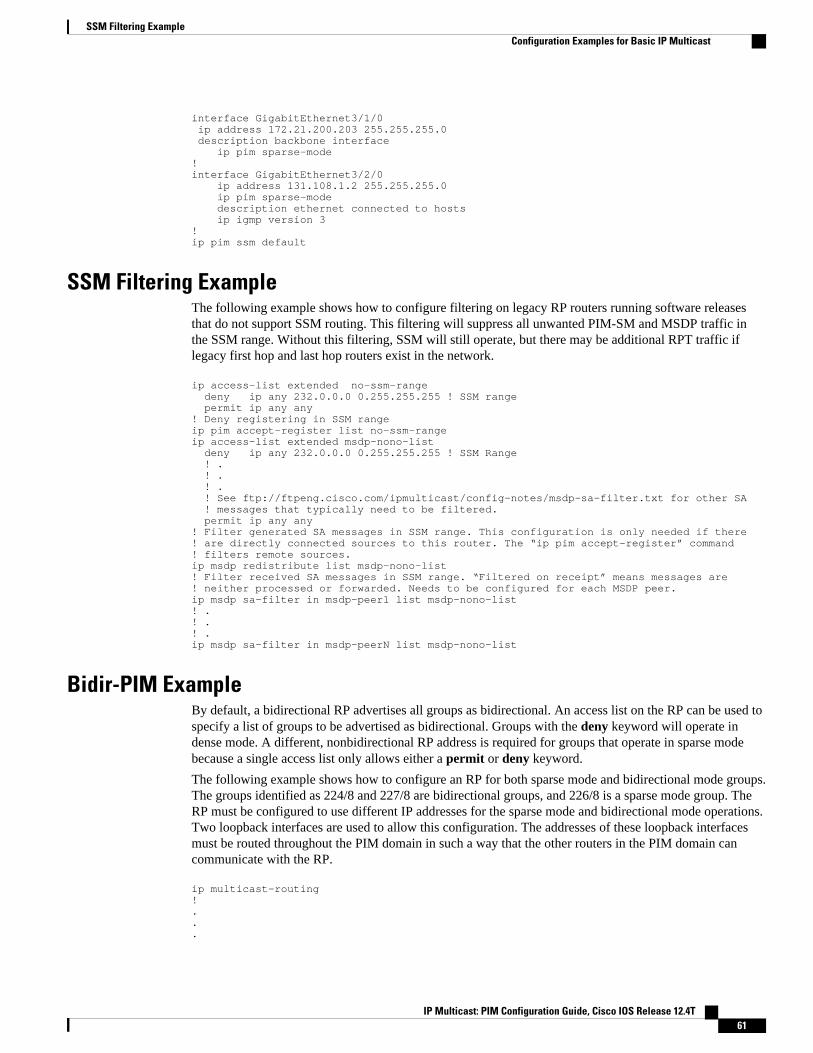
interface GigabitEthernet3/1/0 ip address 172.21.200.203 255.255.255.0 description backbone interface ip pim sparse-mode ! interface GigabitEthernet3/2/0 ip address 131.108.1.2 255.255.255.0 ip pim sparse-mode description ethernet connected to hosts ip igmp version 3 ! ip pim ssm default
SSM Filtering ExampleThe following example shows how to configure filtering on legacy RP routers running software releasesthat do not support SSM routing. This filtering will suppress all unwanted PIM-SM and MSDP traffic inthe SSM range. Without this filtering, SSM will still operate, but there may be additional RPT traffic iflegacy first hop and last hop routers exist in the network.
ip access-list extended no-ssm-range deny ip any 232.0.0.0 0.255.255.255 ! SSM range permit ip any any! Deny registering in SSM rangeip pim accept-register list no-ssm-rangeip access-list extended msdp-nono-list deny ip any 232.0.0.0 0.255.255.255 ! SSM Range ! . ! . ! . ! See ftp://ftpeng.cisco.com/ipmulticast/config-notes/msdp-sa-filter.txt for other SA ! messages that typically need to be filtered. permit ip any any! Filter generated SA messages in SSM range. This configuration is only needed if there! are directly connected sources to this router. The “ip pim accept-register” command! filters remote sources.ip msdp redistribute list msdp-nono-list! Filter received SA messages in SSM range. “Filtered on receipt” means messages are! neither processed or forwarded. Needs to be configured for each MSDP peer.ip msdp sa-filter in msdp-peer1 list msdp-nono-list! .! .! .ip msdp sa-filter in msdp-peerN list msdp-nono-list
Bidir-PIM ExampleBy default, a bidirectional RP advertises all groups as bidirectional. An access list on the RP can be used tospecify a list of groups to be advertised as bidirectional. Groups with the deny keyword will operate indense mode. A different, nonbidirectional RP address is required for groups that operate in sparse modebecause a single access list only allows either a permit or deny keyword.
The following example shows how to configure an RP for both sparse mode and bidirectional mode groups.The groups identified as 224/8 and 227/8 are bidirectional groups, and 226/8 is a sparse mode group. TheRP must be configured to use different IP addresses for the sparse mode and bidirectional mode operations.Two loopback interfaces are used to allow this configuration. The addresses of these loopback interfacesmust be routed throughout the PIM domain in such a way that the other routers in the PIM domain cancommunicate with the RP.
ip multicast-routing!...
SSM Filtering ExampleConfiguration Examples for Basic IP Multicast
IP Multicast: PIM Configuration Guide, Cisco IOS Release 12.4T 61
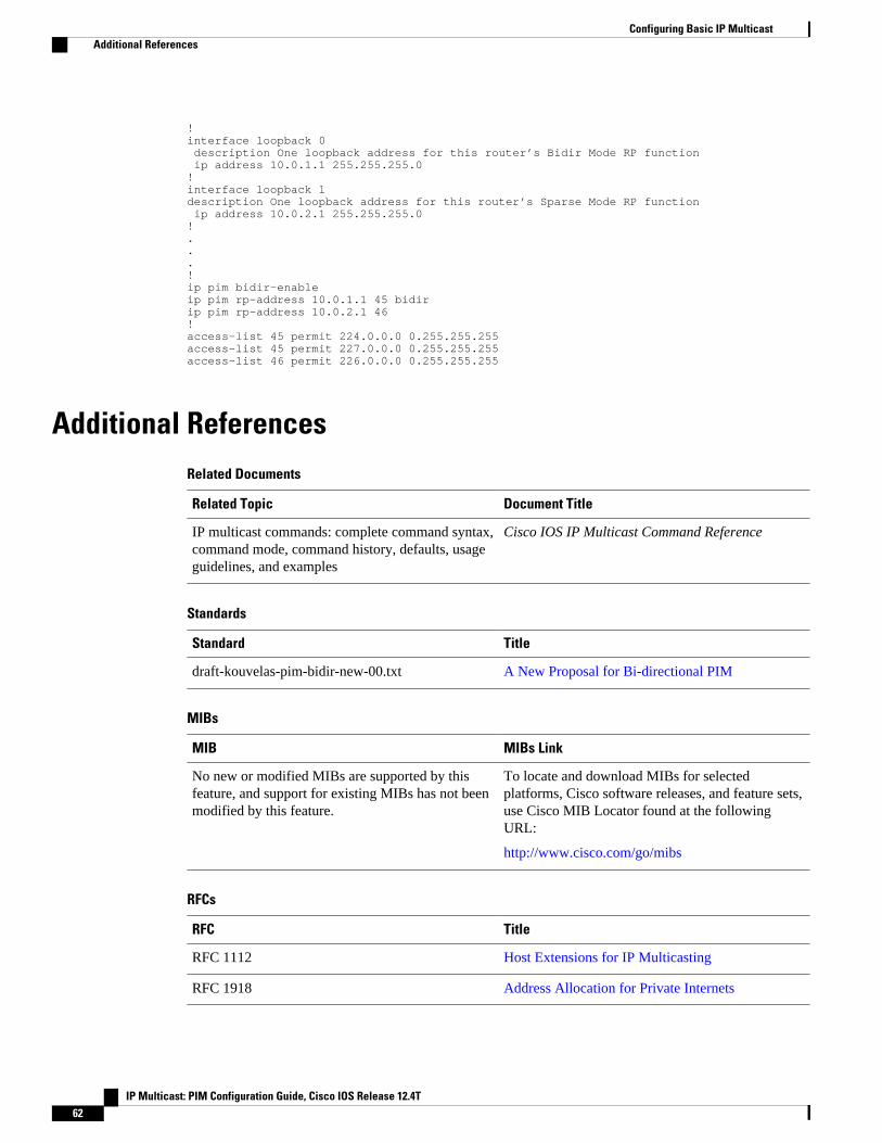
!interface loopback 0 description One loopback address for this router’s Bidir Mode RP function ip address 10.0.1.1 255.255.255.0 ! interface loopback 1 description One loopback address for this router’s Sparse Mode RP function ip address 10.0.2.1 255.255.255.0!...!ip pim bidir-enableip pim rp-address 10.0.1.1 45 bidirip pim rp-address 10.0.2.1 46 !access-list 45 permit 224.0.0.0 0.255.255.255 access-list 45 permit 227.0.0.0 0.255.255.255 access-list 46 permit 226.0.0.0 0.255.255.255
Additional ReferencesRelated Documents
Related Topic Document Title
IP multicast commands: complete command syntax,command mode, command history, defaults, usageguidelines, and examples
Cisco IOS IP Multicast Command Reference
Standards
Standard Title
draft-kouvelas-pim-bidir-new-00.txt A New Proposal for Bi-directional PIM
MIBs
MIB MIBs Link
No new or modified MIBs are supported by thisfeature, and support for existing MIBs has not beenmodified by this feature.
To locate and download MIBs for selectedplatforms, Cisco software releases, and feature sets,use Cisco MIB Locator found at the followingURL:
http://www.cisco.com/go/mibs
RFCs
RFC Title
RFC 1112 Host Extensions for IP Multicasting
RFC 1918 Address Allocation for Private Internets
Configuring Basic IP Multicast Additional References
IP Multicast: PIM Configuration Guide, Cisco IOS Release 12.4T62
RFC Title
RFC 2770 GLOP Addressing in 233/8
RFC 3569 An Overview of Source-Specific Multicast (SSM)
Technical Assistance
Description Link
The Cisco Support website provides extensiveonline resources, including documentation and toolsfor troubleshooting and resolving technical issueswith Cisco products and technologies.
To receive security and technical information aboutyour products, you can subscribe to variousservices, such as the Product Alert Tool (accessedfrom Field Notices), the Cisco Technical ServicesNewsletter, and Really Simple Syndication (RSS)Feeds.
Access to most tools on the Cisco Support websiterequires a Cisco.com user ID and password.
http://www.cisco.com/cisco/web/support/index.html
Feature Information for Configuring Basic IP MulticastThe following table provides release information about the feature or features described in this module.This table lists only the software release that introduced support for a given feature in a given softwarerelease train. Unless noted otherwise, subsequent releases of that software release train also support thatfeature.
Use Cisco Feature Navigator to find information about platform support and Cisco software image support.To access Cisco Feature Navigator, go to www.cisco.com/go/cfn. An account on Cisco.com is not required.
Configuring Basic IP MulticastFeature Information for Configuring Basic IP Multicast
IP Multicast: PIM Configuration Guide, Cisco IOS Release 12.4T 63
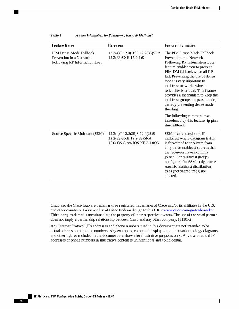
Table 3 Feature Information for Configuring Basic IP Multicast
Feature Name Releases Feature Information
PIM Dense Mode FallbackPrevention in a NetworkFollowing RP Information Loss
12.3(4)T 12.0(28)S 12.2(33)SRA12.2(33)SXH 15.0(1)S
The PIM Dense Mode FallbackPrevention in a NetworkFollowing RP Information Lossfeature enables you to preventPIM-DM fallback when all RPsfail. Preventing the use of densemode is very important tomulticast networks whosereliability is critical. This featureprovides a mechanism to keep themulticast groups in sparse mode,thereby preventing dense modeflooding.
The following command wasintroduced by this feature: ip pimdm-fallback.
Source Specific Multicast (SSM) 12.3(4)T 12.2(25)S 12.0(28)S12.2(33)SXH 12.2(33)SRA15.0(1)S Cisco IOS XE 3.1.0SG
SSM is an extension of IPmulticast where datagram trafficis forwarded to receivers fromonly those multicast sources thatthe receivers have explicitlyjoined. For multicast groupsconfigured for SSM, only source-specific multicast distributiontrees (not shared trees) arecreated.
Cisco and the Cisco logo are trademarks or registered trademarks of Cisco and/or its affiliates in the U.S.and other countries. To view a list of Cisco trademarks, go to this URL: www.cisco.com/go/trademarks.Third-party trademarks mentioned are the property of their respective owners. The use of the word partnerdoes not imply a partnership relationship between Cisco and any other company. (1110R)
Any Internet Protocol (IP) addresses and phone numbers used in this document are not intended to beactual addresses and phone numbers. Any examples, command display output, network topology diagrams,and other figures included in the document are shown for illustrative purposes only. Any use of actual IPaddresses or phone numbers in illustrative content is unintentional and coincidental.
Configuring Basic IP Multicast
IP Multicast: PIM Configuration Guide, Cisco IOS Release 12.4T64
Using MSDP to Interconnect Multiple PIM-SMDomains
This module describes the tasks associated with using Multicast Source Discovery Protocol (MSDP) tointerconnect multiple Protocol Independent Multicast (PIM) Sparse Mode (SM) domains. The tasksexplain how to configure MSDP peers, mesh groups, and default peers, how to use filters to control andscope MSDP activity, and how to monitor and maintain MSDP. Using MSDP with PIM-SM greatlyreduces the complexity of connecting multiple PIM-SM domains.
• Finding Feature Information, page 65• Prerequisites for Using MSDP to Interconnect Multiple PIM-SM Domains, page 65• Information About Using MSDP to Interconnect Multiple PIM-SM Domains, page 66• How to Use MSDP to Interconnect Multiple PIM-SM Domains, page 82• Configuration Examples for Using MSDP to Interconnect Multiple PIM-SM Domains, page 108• Additional References, page 110• Feature Information for Using MSDP to Interconnect Multiple PIM-SM Domains, page 112
Finding Feature InformationYour software release may not support all the features documented in this module. For the latest featureinformation and caveats, see the release notes for your platform and software release. To find informationabout the features documented in this module, and to see a list of the releases in which each feature issupported, see the Feature Information Table at the end of this document.
Use Cisco Feature Navigator to find information about platform support and Cisco software image support.To access Cisco Feature Navigator, go to www.cisco.com/go/cfn. An account on Cisco.com is not required.
Prerequisites for Using MSDP to Interconnect Multiple PIM-SM Domains
Before you configure MSDP, the addresses of all MSDP peers must be known in Border Gateway Protocol(BGP).
IP Multicast: PIM Configuration Guide, Cisco IOS Release 12.4T 65
Information About Using MSDP to Interconnect Multiple PIM-SM Domains
• Benefits of Using MSDP to Interconnect Multiple PIM-SM Domains, page 66
• Use of MSDP to Interconnect Multiple PIM-SM Domains, page 66
• MSDP Message Types, page 69
• SA Message Origination Receipt and Processing, page 70
• MSDP Peers, page 73
• MSDP MD5 Password Authentication, page 74
• SA Message Limits, page 74
• MSDP Keepalive and Hold-Time Intervals, page 74
• MSDP Connection-Retry Interval, page 75
• MSDP Compliance with IETF RFC 3618, page 75
• Default MSDP Peers, page 76
• MSDP Mesh Groups, page 77
• SA Origination Filters, page 78
• Use of Outgoing Filter Lists in MSDP, page 79
• Use of Incoming Filter Lists in MSDP, page 80
• TTL Thresholds in MSDP, page 81
• SA Request Messages, page 81
• SA Request Filters, page 81
• MSDP MIB, page 82
Benefits of Using MSDP to Interconnect Multiple PIM-SM Domains• Allows a rendezvous point (RP) to dynamically discover active sources outside of its domain.• Introduces a more manageable approach for building multicast distribution trees between multiple
domains.
Use of MSDP to Interconnect Multiple PIM-SM DomainsMSDP is a mechanism to connect multiple PIM-SM domains. The purpose of MSDP is to discovermulticast sources in other PIM domains. The main advantage of MSDP is that it reduces the complexity ofinterconnecting multiple PIM-SM domains by allowing PIM-SM domains to use an interdomain source tree(rather than a common shared tree). When MSDP is configured in a network, RPs exchange sourceinformation with RPs in other domains. An RP can join the interdomain source tree for sources that aresending to groups for which it has receivers. The RP can do that because it is the root of the shared treewithin its domain, which has branches to all points in the domain where there are active receivers. When alast-hop router learns of a new source outside the PIM-SM domain (through the arrival of a multicastpacket from the source down the shared tree), it then can send a join toward the source and join theinterdomain source tree.
Benefits of Using MSDP to Interconnect Multiple PIM-SM Domains Information About Using MSDP to Interconnect Multiple PIM-SM Domains
IP Multicast: PIM Configuration Guide, Cisco IOS Release 12.4T66
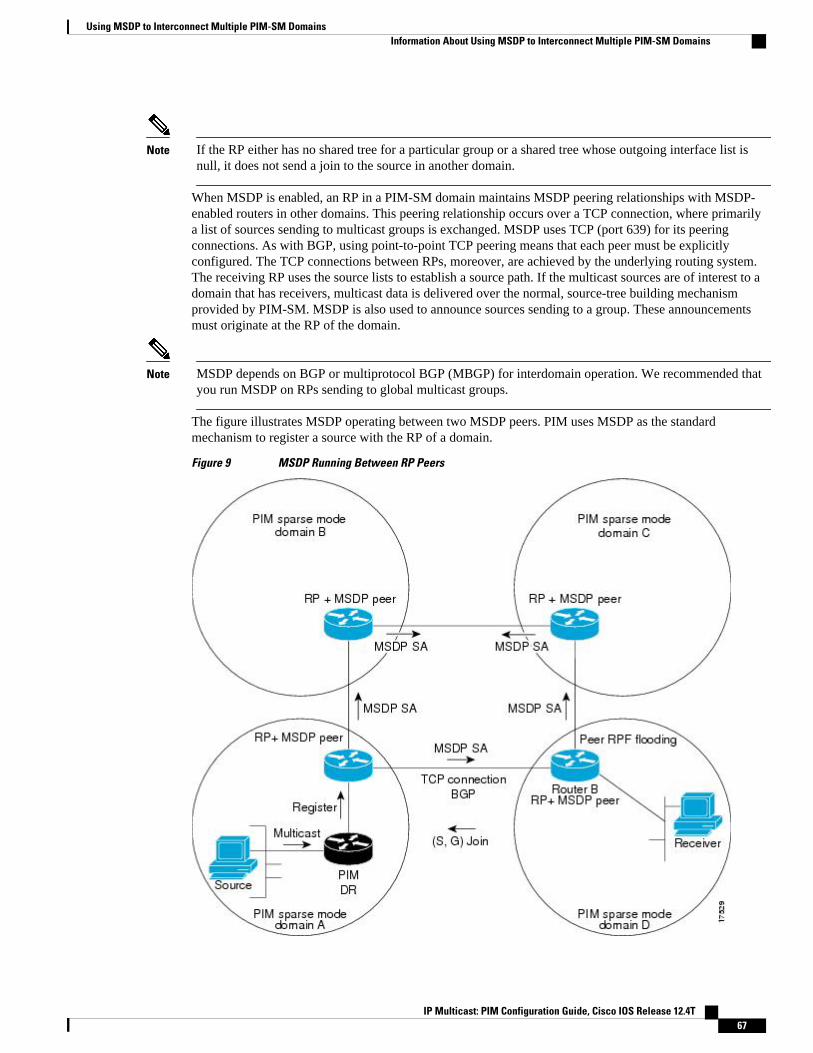
Note If the RP either has no shared tree for a particular group or a shared tree whose outgoing interface list isnull, it does not send a join to the source in another domain.
When MSDP is enabled, an RP in a PIM-SM domain maintains MSDP peering relationships with MSDP-enabled routers in other domains. This peering relationship occurs over a TCP connection, where primarilya list of sources sending to multicast groups is exchanged. MSDP uses TCP (port 639) for its peeringconnections. As with BGP, using point-to-point TCP peering means that each peer must be explicitlyconfigured. The TCP connections between RPs, moreover, are achieved by the underlying routing system.The receiving RP uses the source lists to establish a source path. If the multicast sources are of interest to adomain that has receivers, multicast data is delivered over the normal, source-tree building mechanismprovided by PIM-SM. MSDP is also used to announce sources sending to a group. These announcementsmust originate at the RP of the domain.
Note MSDP depends on BGP or multiprotocol BGP (MBGP) for interdomain operation. We recommended thatyou run MSDP on RPs sending to global multicast groups.
The figure illustrates MSDP operating between two MSDP peers. PIM uses MSDP as the standardmechanism to register a source with the RP of a domain.
Figure 9 MSDP Running Between RP Peers
Using MSDP to Interconnect Multiple PIM-SM DomainsInformation About Using MSDP to Interconnect Multiple PIM-SM Domains
IP Multicast: PIM Configuration Guide, Cisco IOS Release 12.4T 67
When MSDP is implemented, the following sequence of events occurs:
1 When a PIM designated router (DR) registers a source with its RP as illustrated in the figure, the RPsends a Source-Active (SA) message to all of its MSDP peers.
Note The DR sends the encapsulated data to the RP only once per source (when the source goes active). If thesource times out, this process happens again when it goes active again. This situation is different from theperiodic SA message that contains all sources that are registered to the originating RP. Those SA messagesare MSDP control packets, and, thus, do not contain encapsulated data from active sources.
1 The SA message identifies the source address, the group that the source is sending to, and the address orthe originator ID of the RP, if configured.
2 Each MSDP peer that receives the SA message floods the SA message to all of its peers downstreamfrom the originator. In some cases (such as the case with the RPs in PIM-SM domains B and C in thefigure), an RP may receive a copy of an SA message from more than one MSDP peer. To preventlooping, the RP consults the BGP next-hop database to determine the next hop toward the originator ofthe SA message. If both MBGP and unicast BGP are configured, MBGP is checked first, and thenunicast BGP. That next-hop neighbor is the RPF-peer for the originator. SA messages that are receivedfrom the originator on any interface other than the interface to the RPF peer are dropped. The SAmessage flooding process, therefore, is referred to as peer-RPF flooding. Because of the peer-RPFflooding mechanism, BGP or MBGP must be running in conjunction with MSDP.
Note (M)BGP is not required in MSDP mesh group scenarios. For more information about MSDP mesh groups,see the Configuring an MSDP Mesh Group, page 93 section.
Note (M)BGP is not required in default MSDP peer scenarios or in scenarios where only one MSDP peer isconfigured. For more information, see the Configuring a Default MSDP Peer, page 92 section.
1 When an RP receives an SA message, it checks to see whether there are any members of the advertisedgroups in its domain by checking to see whether there are interfaces on the group’s (*, G) outgoinginterface list. If there are no group members, the RP does nothing. If there are group members, the RPsends an (S, G) join toward the source. As a result, a branch of the interdomain source tree isconstructed across autonomous system boundaries to the RP. As multicast packets arrive at the RP, theyare then forwarded down its own shared tree to the group members in the RP’s domain. The members’DRs then have the option of joining the rendezvous point tree (RPT) to the source using standard PIM-SM procedures.
2 The originating RP continues to send periodic SA messages for the (S, G) state every 60 seconds for aslong as the source is sending packets to the group. When an RP receives an SA message, it caches theSA message. Suppose, for example, that an RP receives an SA message for (172.16.5.4, 228.1.2.3) fromoriginating RP 10.5.4.3. The RP consults its mroute table and finds that there are no active members forgroup 228.1.2.3, so it passes the SA message to its peers downstream of 10.5.4.3. If a host in thedomain then sends a join to the RP for group 228.1.2.3, the RP adds the interface toward the host to theoutgoing interface list of its (*, 224.1.2.3) entry. Because the RP caches SA messages, the router willhave an entry for (172.16.5.4, 228.1.2.3) and can join the source tree as soon as a host requests a join.
Using MSDP to Interconnect Multiple PIM-SM Domains Information About Using MSDP to Interconnect Multiple PIM-SM Domains
IP Multicast: PIM Configuration Guide, Cisco IOS Release 12.4T68
Note In all current and supported software releases, caching of MSDP SA messages is mandatory and cannot bemanually enabled or disabled. By default, when an MSDP peer is configured, the ip multicast cache-sa-state command will automatically be added to the running configuration.
MSDP Message TypesThere are four basic MSDP message types, each encoded in their own Type, Length, and Value (TLV) dataformat.
• SA Messages, page 69
• SA Request Messages, page 69
• SA Response Messages, page 69
• Keepalive Messages, page 70
SA MessagesSA messages are used to advertise active sources in a domain. In addition, these SA messages may containthe initial multicast data packet that was sent by the source.
SA messages contain the IP address of the originating RP and one or more (S, G) pairs being advertised. Inaddition, the SA message may contain an encapsulated data packet.
Note For more information about SA messages, see the SA Message Origination Receipt and Processing, page70 section.
SA Request MessagesSA request messages are used to request a list of active sources for a specific group. These messages aresent to an MSDP SA cache that maintains a list of active (S, G) pairs in its SA cache. Join latency can bereduced by using SA request messages to request the list of active sources for a group instead of having towait up to 60 seconds for all active sources in the group to be readvertised by originating RPs.
Note For more information about SA request messages, see the Requesting Source Information from MSDPPeers, page 98 section.
SA Response MessagesSA response messages are sent by the MSDP peer in response to an SA request message. SA responsemessages contain the IP address of the originating RP and one or more (S, G) pairs of the active sources inthe originating RP’s domain that are stored in the cache.
MSDP Message TypesSA Messages
IP Multicast: PIM Configuration Guide, Cisco IOS Release 12.4T 69
Note For more information about SA response messages, see the Controlling the Response to Outgoing SARequest Messages from MSDP Peers Using SA Request Filters, page 100 section.
Keepalive MessagesKeepalive messages are sent every 60 seconds in order to keep the MSDP session active. If no keepalivemessages or SA messages are received for 75 seconds, the MSDP session is reset.
Note For more information about keepalive messages, see the Adjusting the MSDP Keepalive and Hold-TimeIntervals, page 88 section.
SA Message Origination Receipt and ProcessingThe section describes SA message origination, receipt, and processing in detail.
• SA Message Origination, page 70• SA Message Receipt, page 70• SA Message Processing, page 73
SA Message OriginationSA messages are triggered by an RP (assuming MSDP is configured) when any new source goes activewithin a local PIM-SM domain. A local source is a source that is directly connected to the RP or is the first-hop DR that has registered with it. An RP originates SA messages only for local sources in its PIM-SMdomain; that is, for local sources that register with it.
Note A local source is denoted by the A flag being set in the (S, G) mroute entry on the RP (which can beviewed in the output of the show ip mroute command). This flag indicates that the source is a candidatefor advertisement by the RP to other MSDP peers.
When a source is in the local PIM-SM domain, it causes the creation of (S, G) state in the RP. New sourcesare detected by the RP either by the receipt of a register message or the arrival of the first (S, G) packetfrom a directly connected source. The initial multicast packet sent by the source (either encapsulated in theregister message or received from a directly connected source) is encapsulated in the initial SA message.
SA Message ReceiptSA messages are only accepted from the MSDP RPF peer that is in the best path back toward theoriginator. The same SA message arriving from other MSDP peers must be ignored or SA loops can occur.Deterministically selecting the MSDP RPF peer for an arriving SA message requires knowledge of theMSDP topology. However, MSDP does not distribute topology information in the form of routing updates.MSDP infers this information by using (M)BGP routing data as the best approximation of the MSDPtopology for the SA RPF check mechanism. An MSDP topology, therefore, must follow the same generaltopology as the BGP peer topology. Besides a few exceptions (such as default MSDP peers and MSDPpeers in MSDP mesh groups), MSDP peers, in general should also be (M)BGP peers.
SA Message Origination Receipt and Processing Keepalive Messages
IP Multicast: PIM Configuration Guide, Cisco IOS Release 12.4T70
• How RPF Check Rules Are Applied to SA Messages, page 71
• How the Software Determines the Rule to Apply to RPF Checks, page 71
• Rule 1 of RPF Checking of SA Messages in MSDP, page 71
• Implications of Rule 1 of RPF Checking on MSDP, page 72
• Rule 2 of RPF Checking of SA Messages in MSDP, page 72
• Implications of Rule 2 of RPF Checking on MSDP, page 72
• Rule 3 of RPF Checking of SA Messages in MSDP, page 73
How RPF Check Rules Are Applied to SA Messages
The rules that apply to RPF checks for SA messages are dependent on the BGP peerings between theMSDP peers:
• Rule 1: Applied when the sending MSDP peer is also an interior (M)BGP peer.• Rule 2: Applied when the sending MSDP peer is also an exterior (M)BGP peer.• Rule 3: Applied when the sending MSDP peer is not an (M)BGP peer.
RPF checks are not performed in the following cases:
• If the sending MSDP peer is the only MSDP peer, which would be the case if only a single MSDPpeer or a default MSDP peer is configured.
• If the sending MSDP peer is a member of a mesh group.• If the sending MSDP peer address is the RP address contained in the SA message.
How the Software Determines the Rule to Apply to RPF Checks
The software uses the following logic to determine which RPF rule to apply to RPF checks:
• Find the (M)BGP neighbor that has the same IP address as the sending MSDP peer.
◦ If the matching (M)BGP neighbor is an internal BGP (iBGP) peer, apply Rule 1.◦ If the matching (M)BGP neighbor is an external BGP (eBGP) peer, apply Rule 2.◦ If no match is found, apply Rule 3.
Note The implication of the RPF check rule selection is as follows: The IP address used to configure an MSDPpeer on a router must match the IP address used to configure the (M)BGP peer on the same router.
Rule 1 of RPF Checking of SA Messages in MSDP
Rule 1 of RPF checking in MSDP is applied when the sending MSDP peer is also an i(M)BGP peer. WhenRule 1 is applied, the RPF check proceeds as follows:
1 The peer searches the BGP Multicast Routing Information Base (MRIB) for the best path to the RP thatoriginated the SA message. If a path is not found in the MRIB, the peer then searches the UnicastRouting Information Base (URIB). If a path is still not found, the RPF check fails.
2 If the previous search succeeds (that is, the best path is found), the peer then determines the address ofthe BGP neighbor for this best path, which will be the address of the BGP neighbor that sent the peerthe path in BGP update messages.
Using MSDP to Interconnect Multiple PIM-SM DomainsHow RPF Check Rules Are Applied to SA Messages
IP Multicast: PIM Configuration Guide, Cisco IOS Release 12.4T 71
Note The BGP neighbor address is not the same as the next-hop address in the path. Because i(M)BGP peers donot update the next-hop attribute of a path, the next-hop address usually is not the same as the address ofthe BGP peer that sent us the path.
Note The BGP neighbor address is not necessarily the same as the BGP router ID of the peer that sent the peerthe path.
1 If the IP address of the sending MSDP peer is the same as the BGP neighbor address (that is, theaddress of the BGP peer that sent the peer the path), then the RPF check succeeds; otherwise it fails.
Implications of Rule 1 of RPF Checking on MSDP
The MSDP topology must mirror the (M)BGP topology. In general, wherever there is an i(M)BGP peerconnection between two routers, an MSDP peer connection should be configured. More specifically, the IPaddress of the far-end MSDP peer connection must be the same as the far-end i(M)BGP peer connection.The addresses must be the same because the BGP topology between i(M)BGP peers inside an autonomoussystem is not described by the AS path. If it were always the case that i(M)BGP peers updated the next-hopaddress in the path when sending an update to another i(M)BGP peer, then the peer could rely on the next-hop address to describe the i(M)BGP topology (and hence the MSDP topology). However, because thedefault behavior for i(M)BGP peers is to not update the next-hop address, the peer cannot rely on the next-hop address to describe the (M)BGP topology (MSDP topology). Instead, the i(M)BGP peer uses theaddress of the i(M)BGP peer that sent the path to describe the i(M)BGP topology (MSDP topology) insidethe autonomous system.
Tip Care should be taken when configuring the MSDP peer addresses to make sure that the same address isused for both i(M)BGP and MSDP peer addresses.
Rule 2 of RPF Checking of SA Messages in MSDP
Rule 2 of RPF checking in MSDP is applied when the sending MSDP peer is also an e(M)BGP peer. WhenRule 2 is applied, the RPF check proceeds as follows:
1 The peer searches the BGP MRIB for the best path to the RP that originated the SA message. If a path isnot found in the MRIB, the peer then searches the URIB. If a path is still not found, the RPF check fails.
2 If the previous search succeeds (that is, the best path is found), the peer then examines the path. If thefirst autonomous system in the best path to the RP is the same as the autonomous system of thee(M)BGP peer (which is also the sending MSDP peer), then the RPF check succeeds; otherwise it fails.
Implications of Rule 2 of RPF Checking on MSDP
The MSDP topology must mirror the (M)BGP topology. In general, wherever there is an e(M)BGP peerconnection between two routers, an MSDP peer connection should be configured. As opposed to Rule 1,the IP address of the far-end MSDP peer connection does not have to be the same as the far-end e(M)BGPpeer connection.The reason that the addresses do not have to be identical is that BGP topology between twoe(M)BGP peers is not described by the AS path.
Using MSDP to Interconnect Multiple PIM-SM Domains Implications of Rule 1 of RPF Checking on MSDP
IP Multicast: PIM Configuration Guide, Cisco IOS Release 12.4T72
Rule 3 of RPF Checking of SA Messages in MSDP
Rule 3 of RPF checking is applied when the sending MSDP peer is not a (M)BGP peer at all. When Rule 3is applied, the RPF check proceeds as follows:
1 The peer searches the BGP MRIB for the best path to the RP that originated the SA message. If a path isnot found in the MRIB, the peer then searches the URIB. If a path is still not found, the RPF check fails.
2 If the previous search succeeds (that is, the best path to the RP that originated the SA message is found),the peer then searches the BGP MRIB for the best path to the MSDP peer that sent the SA message. If apath is not found in the MRIB, the peer then searches the URIB. If a path is still not found, the RPFcheck fails.
Note The autonomous system of the MSDP peer that sent the SA is the origin autonomous system, which is thelast autonomous system in the AS path to the MSDP peer.
1 If the first autonomous system in the best path to the RP is the same as the autonomous system of thesending MSDP peer, then the RPF check succeeds; otherwise it fails.
SA Message ProcessingThe following steps are taken by an MSDP peer whenever it processes an SA message:
1 Using the group address G of the (S, G) pair in the SA message, the peer locates the associated (*, G)entry in the mroute table. If the (*, G) entry is found and its outgoing interface list is not null, then thereare active receivers in the PIM-SM domain for the source advertised in the SA message.
2 The MSDP peer then creates an (S, G) entry for the advertised source.3 If the (S, G) entry did not already exist, the MSDP peer immediately triggers an (S, G) join toward the
source in order to join the source tree.4 The peer then floods the SA message to all other MSDP peers with the exception of:
• The MSDP peer from which the SA message was received.• Any MSDP peers that are in the same MSDP mesh group as this router (if the peer is a member of
a mesh group).
Note SA messages are stored locally in the router’s SA cache.
MSDP PeersLike BGP, MSDP establishes neighbor relationships with other MSDP peers. MSDP peers connect usingTCP port 639. The lower IP address peer takes the active role of opening the TCP connection. The higherIP address peer waits in LISTEN state for the other to make the connection. MSDP peers send keepalivemessages every 60 seconds. The arrival of data performs the same function as the keepalive message andkeeps the session from timing out. If no keepalive messages or data is received for 75 seconds, the TCPconnection is reset.
MSDP PeersRule 3 of RPF Checking of SA Messages in MSDP
IP Multicast: PIM Configuration Guide, Cisco IOS Release 12.4T 73
MSDP MD5 Password AuthenticationThe MSDP MD5 password authentication feature is an enhancement to support Message Digest 5 (MD5)signature protection on a TCP connection between two MSDP peers. This feature provides added securityby protecting MSDP against the threat of spoofed TCP segments being introduced into the TCP connectionstream.
• How MSDP MD5 Password Authentication Works, page 74• Benefits of MSDP MD5 Password Authentication, page 74
How MSDP MD5 Password Authentication WorksDeveloped in accordance with RFC 2385, the MSDP MD5 password authentication feature is used toverify each segment sent on the TCP connection between MSDP peers. The ip msdp password peercommand is used to enable MD5 authentication for TCP connections between two MSDP peers. WhenMD5 authentication is enabled between two MSDP peers, each segment sent on the TCP connectionbetween the peers is verified. MD5 authentication must be configured with the same password on bothMSDP peers; otherwise, the connection between them will not be made. Configuring MD5 authenticationcauses the Cisco IOS software to generate and verify the MD5 digest of every segment sent on the TCPconnection.
Benefits of MSDP MD5 Password Authentication
• Protects MSDP against the threat of spoofed TCP segments being introduced into the TCP connectionstream.
• Uses the industry-standard MD5 algorithm for improved reliability and security.
SA Message LimitsThe ip msdp sa-limit command is used to limit the overall number of SA messages that a router can acceptfrom specified MSDP peers. When the ip msdp sa-limit command is configured, the router maintains aper-peer count of SA messages stored in the SA cache and will ignore new messages from a peer if theconfigured SA message limit for that peer has been reached.
The ip msdp sa-limit command was introduced as a means to protect an MSDP-enabled router from denialof service (DoS) attacks. We recommended that you configure SA message limits for all MSDP peeringson the router. An appropriately low SA limit should be configured on peerings with a stub MSDP region(for example, a peer that may have some further downstream peers but that will not act as a transit for SAmessages across the rest of the Internet). A high SA limit should be configured for all MSDP peerings thatact as transits for SA messages across the Internet.
MSDP Keepalive and Hold-Time IntervalsThe ip msdp keepalive command is used to adjust the interval at which an MSDP peer will send keepalivemessages and the interval at which the MSDP peer will wait for keepalive messages from other peersbefore declaring them down.
Once an MSDP peering session is established, each side of the connection sends a keepalive message andsets a keepalive timer. If the keepalive timer expires, the local MSDP peer sends a keepalive message andrestarts its keepalive timer; this interval is referred to as the keepalive interval. The keepalive-intervalargument is used to adjust the interval for which keepalive messages will be sent. The keepalive
MSDP MD5 Password Authentication How MSDP MD5 Password Authentication Works
IP Multicast: PIM Configuration Guide, Cisco IOS Release 12.4T74
timer is set to the value specified for the keepalive-intervalargument when the peer comes up. Thekeepalive timer is reset to the value of the keepalive-interval argument whenever an MSDP keepalivemessage is sent to the peer and reset when the timer expires. The keepalive timer is deleted when an MSDPpeering session is closed. By default, the keepalive timer is set to 60 seconds.
Note The value specified for the keepalive-interval argument must be less than the value specified for theholdtime-intervalargument and must be at least one second.
The hold-time timer is initialized to the value of the hold-time-interval argument whenever an MSDPpeering connection is established, and is reset to the value of the hold-time-intervalargument whenever anMSDP keepalive message is received. The hold-time timer is deleted whenever an MSDP peeringconnection is closed. By default, the hold-time interval is set to 75 seconds.
Use the hold-time-interval argument to adjust the interval at which the MSDP peer will wait for keepalivemessages from other peers before declaring them down.
MSDP Connection-Retry IntervalThe ip msdp timer command is used to adjust the interval at which all MSDP peers will wait after peeringsessions are reset before attempting to reestablish the peering sessions. This interval is referred to as theconnection-retry interval. By default, MSDP peers will wait 30 seconds after the session is reset beforeattempting to reestablish sessions with other peers. When the ip msdp timer command is configured, theconfigured connection-retry interval applies to all MSDP peering sessions on the router.
MSDP Compliance with IETF RFC 3618When the MSDP Compliance with IETF RFC 3618 feature is configured, the peer-RPF forwarding rulesdefined in IETF RFC 3618 are applied to MSDP peers. IETF RFC 3618 provides peer-RPF forwardingrules that are used for forwarding SA messages throughout an MSDP-enabled internet. Unlike the RPFcheck used when forwarding data packets, which compares a packet’s source address against the interfaceupon which the packet was received, the peer-RPF check compares the RP address carried in the SAmessage against the MSDP peer from which the message was received. Except when MSDP mesh groupsare being used, SA messages from an RP address are accepted from only one MSDP peer to avoid loopingSA messages.
Note For more information about the MSDP peer-forwarding rules defined in RFC 3618, see RFC 3618, Multicast Source Discovery Protocol (MSDP) .
• Benefits of MSDP Compliance with RFC 3618, page 75
Benefits of MSDP Compliance with RFC 3618
• You can use BGP route reflectors (RRs) without running MSDP on them. This capability is useful toservice providers that need to reduce the load on RRs.
• You can use an Interior Gateway Protocol (IGP) for the Reverse Path Forwarding (RPF) checks andthereby run peerings without (M)BGP. This capability is useful to enterprise customers that do not run(M)BGP and require larger topologies than mesh groups can provide.
MSDP Connection-Retry IntervalBenefits of MSDP Compliance with RFC 3618
IP Multicast: PIM Configuration Guide, Cisco IOS Release 12.4T 75
Note IGP peerings must always be between directly connected MSDP peers or else the RPF checks will fail.
• You can have peerings between routers in nondirectly connected autonomous systems (that is, withone or more autonomous systems between them). This capability helps in confederation configurationsand for redundancy.
Default MSDP PeersIn most scenarios, an MSDP peer is also a BGP peer. If an autonomous system is a stub or nontransitautonomous system, and particularly if the autonomous system is not multihomed, there is little or noreason to run BGP to its transit autonomous system. A static default route at the stub autonomous system,and a static route pointing to the stub prefixes at the transit autonomous system, is generally sufficient. Butif the stub autonomous system is also a multicast domain and its RP must peer with an RP in theneighboring domain, MSDP depends on the BGP next-hop database for its peer-RPF checks. You candisable this dependency on BGP by defining a default peer from which to accept all SA messages withoutperforming the peer-RPF check, using the ip msdp default-peer command. A default MSDP peer must bea previously configured MSDP peer.
A stub autonomous system also might want to have MSDP peerings with more than one RP for the sake ofredundancy. For example, SA messages cannot just be accepted from multiple default peers, because thereis no RPF check mechanism. Instead, SA messages are accepted from only one peer. If that peer fails, SAmessages are then accepted from the other peer. The underlying assumption here, of course, is that bothdefault peers are sending the same SA messages.
The figure illustrates a scenario where default MSDP peers might be used. In the figure, a customer thatowns Router B is connected to the Internet through two Internet service providers (ISPs), one that ownsRouter A and the other that owns Router C. They are not running BGP or MBGP between them. In orderfor the customer to learn about sources in the ISP domain or in other domains, Router B identifies Router Aas its default MSDP peer. Router B advertises SA messages to both Router A and Router C, but accepts SAmessages either from Router A only or Router C only. If Router A is the first default peer in theconfiguration, it will be used if it is up and running. Only if Router A is not running will Router B acceptSA messages from Router C.
The ISP will also likely use a prefix list to define which prefixes it will accept from the customer router.The customer will define multiple default peers, each having one or more prefixes associated with it.
Default MSDP Peers Benefits of MSDP Compliance with RFC 3618
IP Multicast: PIM Configuration Guide, Cisco IOS Release 12.4T76
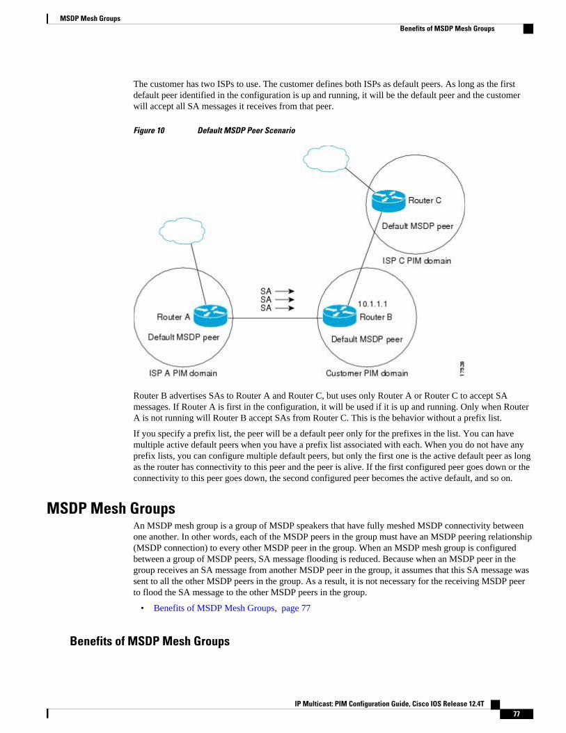
The customer has two ISPs to use. The customer defines both ISPs as default peers. As long as the firstdefault peer identified in the configuration is up and running, it will be the default peer and the customerwill accept all SA messages it receives from that peer.
Figure 10 Default MSDP Peer Scenario
Router B advertises SAs to Router A and Router C, but uses only Router A or Router C to accept SAmessages. If Router A is first in the configuration, it will be used if it is up and running. Only when RouterA is not running will Router B accept SAs from Router C. This is the behavior without a prefix list.
If you specify a prefix list, the peer will be a default peer only for the prefixes in the list. You can havemultiple active default peers when you have a prefix list associated with each. When you do not have anyprefix lists, you can configure multiple default peers, but only the first one is the active default peer as longas the router has connectivity to this peer and the peer is alive. If the first configured peer goes down or theconnectivity to this peer goes down, the second configured peer becomes the active default, and so on.
MSDP Mesh GroupsAn MSDP mesh group is a group of MSDP speakers that have fully meshed MSDP connectivity betweenone another. In other words, each of the MSDP peers in the group must have an MSDP peering relationship(MSDP connection) to every other MSDP peer in the group. When an MSDP mesh group is configuredbetween a group of MSDP peers, SA message flooding is reduced. Because when an MSDP peer in thegroup receives an SA message from another MSDP peer in the group, it assumes that this SA message wassent to all the other MSDP peers in the group. As a result, it is not necessary for the receiving MSDP peerto flood the SA message to the other MSDP peers in the group.
• Benefits of MSDP Mesh Groups, page 77
Benefits of MSDP Mesh Groups
MSDP Mesh GroupsBenefits of MSDP Mesh Groups
IP Multicast: PIM Configuration Guide, Cisco IOS Release 12.4T 77
• Optimizes SA flooding--MSDP mesh groups are particularly useful for optimizing SA flooding whentwo or more peers are in a group.
• Reduces the amount of SA traffic across the Internet--When MSDP mesh groups are used, SAmessages are not flooded to other mesh group peers.
• Eliminates RPF checks on arriving SA messages--When an MSDP mesh group is configured, SAmessages are always accepted from mesh group peers.
SA Origination FiltersBy default, an RP that is configured to run MSDP will originate SA messages for all local sources forwhich it is the RP. Local sources that register with an RP, therefore, will be advertised in SA messages,which in some cases is not desirable. For example, if sources inside a PIM-SM domain are using privateaddresses (for example, network 10.0.0.0/8), you should configure an SA origination filter to restrict thoseaddresses from being advertised to other MSDP peers across the Internet.
To control what sources are advertised in SA messages, you can configure SA origination filters on an RPusing the ip msdp redistribute command. By creating SA origination filters, you can control the sourcesadvertised in SA messages as follows:
• You can prevent an RP from originating SA messages for local sources by configuring the ip msdpredistribute command without any keywords or arguments. Issuing this form of the commandeffectively prevents the router from advertising local sources in SA messages.
Note When the ip msdp redistribute command is entered without any keywords or arguments, the router willstill forward SA messages from other MSDP peers in the normal fashion; it will just not originate any SAmessages for local sources.
• You can configure the router to originate SA messages only for (S, G) pairs defined in an extendedaccess list by configuring the ip msdp redistribute command with the optional list keyword andaccess-list argument. Issuing the form of the command effectively configures the router to onlyoriginate SA messages for local sources sending to specific groups that match (S, G) pairs defined inthe extended access list. All other local sources will not be advertised in SA messages.
• You can configure the router to originate SA messages only for AS paths defined in an AS-path accesslist by configuring the ip msdp redistribute command with the optional asn keyword and as-access-list argument. Issuing this form of the command effectively configures the router to only originate SAmessages for local sources sending to specific groups that the match AS paths defined in an AS-pathaccess list. All other local sources will not be advertised in SA messages.
Note AS-path access lists are configured using the ip as-path access-list command.
You can configure the router to originate SA messages only for local sources that match the criteria definedin a route map by configuring the ip msdp redistributecommand with the optional route-map keywordand map-name argument. Issuing this form of the command effectively configures the router to onlyoriginate SA messages for local sources that match the criteria defined in the route map. All other localsources will not be advertised in SA messages.
SA Origination Filters Benefits of MSDP Mesh Groups
IP Multicast: PIM Configuration Guide, Cisco IOS Release 12.4T78
Note You can configure an SA origination filter that includes an extended access list, an AS-path access list, androute map (or a combination thereof). In that case, all conditions must be true before any local sources areadvertised in SA messages.
Use of Outgoing Filter Lists in MSDPBy default, an MSDP-enabled router forwards all SA messages it receives to all of its MSDP peers.However, you can prevent SA messages from being forwarded to MSDP peers by creating outgoing filterlists using the ip msdp sa-filter out command. Outgoing filter lists (configured using the ip msdp sa-filteroutcommand) apply to all SA messages, whether locally originated or received from another MSDP peer,whereas SA origination filters (configured using the ip msdp redistribute command) apply only to locallyoriginated SA messages. For more information about using the ip msdp redistribute command to enable afilter for MSDP SA messages originated by the local router, see the Controlling SA Messages Originatedby an RP for Local Sources, page 94 section.
By creating an outgoing filter list, you can control the SA messages that a router forwards to a peer asfollows:
• You can filter all outgoing SA messages forwarded to a specified MSDP peer by configuring the ipmsdp filter-sa-request outcommand without any keywords or arguments. Issuing this form of thecommand effectively configures the router to stop forwarding its SA messages to the MSDP peer.
• You can filter a subset of outgoing SA messages forwarded to a specified MSDP peer based on (S, G)pairs defined in an extended access list by configuring the ip msdp sa-filter outcommand with theoptional list keyword and access-list argument. Issuing the form of the command effectivelyconfigures the router to only forward SA messages to the MSDP peer that match the (S, G) pairspermitted in an extended access list. The forwarding of all other SA messages to the MSDP peer willbe stopped.
• You can filter a subset of outgoing SA messages forwarded to a specified MSDP peer based on matchcriteria defined in a route map by configuring the ip msdp sa-filter outcommand with the optionalroute-map keyword and map-name argument. Issuing this form of the command effectivelyconfigures the router to only forward SA messages that match the criteria defined in the route map.The forwarding of all other SA messages to the MSDP peer will be stopped.
• You can filter a subset of outgoing SA messages from a specified peer based on the announcing RPaddress contained in the SA message by configuring the ip msdp sa-filter outcommand with theoptional rp-list keyword and list argument or with the rp-route-map keyword map-nameargument.This type of outgoing filter list enables the router to filter outgoing SA messages based on their origin,even after an SA message has been transmitted across one or more MSDP peers. The forwarding of allother SA messages to the MSDP peer will be stopped.
Note You can configure an outgoing filter list that includes an extended access list, a route map, and either an RPaccess list or an RP route map. In that case, all conditions must be true for the MSDP peer to forward theoutgoing SA message.
Use of Outgoing Filter Lists in MSDPBenefits of MSDP Mesh Groups
IP Multicast: PIM Configuration Guide, Cisco IOS Release 12.4T 79
Caution Arbitrary filtering of SA messages can result in downstream MSDP peers being starved of SA messages forlegitimate active sources. Care, therefore, should be taken when using these sorts of filters. Normally,outgoing filter lists are used only to reject undesirable sources, such as sources using private addresses.
Use of Incoming Filter Lists in MSDPBy default, an MSDP-enabled router receives all SA messages sent to it from its MSDP peers. However,you can control the source information that a router receives from its MSDP peers by creating incomingfilter lists using the ip msdp sa-filter in command.
By creating incoming filter lists, you can control the incoming SA messages that a router receives from itspeers as follows:
• You can filter all incoming SA messages from a specified MSDP peer by configuring the ip msdpfilter-sa-request in command without any keywords or arguments. Issuing this form of the commandeffectively configures the router to ignore all SA messages sent to it from the specified MSDP peer.
• You can filter a subset of incoming SA messages from a specified peer based on (S, G) pairs definedin an extended access list by configuring the ip msdp sa-filter in command with the optional listkeyword and access-list argument. Issuing the form of the command effectively configures the routerto only receive SA messages from the MSDP peer that match the (S, G) pairs defined in the extendedaccess list. All other incoming SA messages from the MSDP peer will be ignored.
• You can filter a subset of incoming SA request messages from a specified peer based on match criteriadefined in a route map by configuring the ip msdp sa-filter incommand with the optional route-mapkeyword and map argument. Issuing this form of the command effectively configures the router toonly receive SA messages that match the criteria defined in the route map. All other incoming SAmessages from the MSDP peer will be ignored.
• You can filter a subset of incoming SA messages from a specified peer based on both (S, G) pairsdefined in an extended access list and on match criteria defined in a route map by configuring the ipmsdp sa-filter incommand with the optional list keyword and access-list argument and with theoptional route-map keyword and map-name argument. Issuing this form of the command configuresthe router to only receive incoming SA messages that both match the (S, G) pairs defined in theextended access list and match the criteria defined in the route map. All other incoming SA messagesfrom the MSDP peer will be ignored.
• You can filter a subset of incoming SA messages from a specified peer based on the announcing RPaddress contained in the SA message by configuring the ip msdp sa-filter in command with theoptional rp-list keyword and list argument or with the rp-route-map map-name. This type ofincoming filter list enables the router to filter incoming SA messages based on their origin, even afterthe SA message may have already been transmitted across one or more MSDP peers.
Note You can configure an incoming filter list that includes an extended access list, a route map, and either anRP access list or an RP route map. In that case, all conditions must be true for the MSDP peer to receive theincoming SA message.
Use of Incoming Filter Lists in MSDP Benefits of MSDP Mesh Groups
IP Multicast: PIM Configuration Guide, Cisco IOS Release 12.4T80
Caution Arbitrary filtering of SA messages can result in downstream MSDP peers being starved of SA messages forlegitimate active sources. Care, therefore, should be taken when using these sorts of filters. Normally,incoming filter lists are used only to reject undesirable sources, such as sources using private addresses.
TTL Thresholds in MSDPThe time-to-live (TTL) value provides a means to limit the number of hops a packet can take before beingdropped. The ip multicast ttl-threshold command is used to specify a TTL for data-encapsulated SAmessages sent to specified MSDP peers. By default, multicast data packets in SA messages are sent to anMSDP peer, provided the TTL value of the packet is greater than 0, which is standard TTL behavior.
In general, a TTL-threshold problem can be introduced by the encapsulation of a source’s initial multicastpacket in an SA message. Because the multicast packet is encapsulated inside of the unicast SA message(whose TTL is 255), its TTL is not decremented as the SA message travels to the MSDP peer. Furthermore,the total number of hops that the SA message traverses can be drastically different than a normal multicastpacket because multicast and unicast traffic may follow completely different paths to the MSDP peer andhence the remote PIM-SM domain. As a result, encapsulated packets can end up violating TTL thresholds.The solution to this problem is to configure a TTL threshold that is associated with any multicast packetthat is encapsulated in an SA message sent to a particular MSDP peer using the ip multicast ttl-thresholdcommand. The ip msdp ttl-threshold command prevents any multicast packet whose TTL in the IP headeris less than the TTL value specified for the ttl-valueargument from being encapsulated in SA messages sentto that peer.
SA Request MessagesThe ip msdp sa-request command is used to enable a noncaching router to send SA request messages to aspecified MSDP peer. You can enter this command multiple times to specify that the router send SArequest messages to additional MSDP peers.
If an noncaching RP has an MSDP peer that is caching SAs, you can reduce the join latency for anoncaching peer by enabling the noncaching peer to send SA request messages. When a host requests a jointo a particular group, the noncaching RP sends an SA request message to its caching peers. If a peer hascached source information for the group in question, it sends the information to the requesting RP with anSA response message. The requesting RP uses the information in the SA response but does not forward themessage to any other peers. If a noncaching RP receives an SA request, it sends an error message back tothe requestor.
Note In all current and supported Cisco IOS software releases, caching of MSDP SA messages is mandatory andcannot be manually enabled or disabled. By default, when an MSDP peer is configured, the ip multicastcache-sa-state command will automatically be added to the running configuration. Prior to Cisco IOSReleases 12.1(7) and 12.0(14)S1, caching of SAs was disabled by default and could be enabled with the ipmsdp cache-sa-state command.
SA Request FiltersBy default, a router honors all outgoing SA request messages from its MSDP peers; that is, it sends cachedsource information to requesting MSDP peers in SA response messages. You can control the outgoing SA
TTL Thresholds in MSDPBenefits of MSDP Mesh Groups
IP Multicast: PIM Configuration Guide, Cisco IOS Release 12.4T 81
request messages that a router will honor from specified peers by enabling an SA request filter using the ipmsdp filter-sa-request command. By creating an SA request filter, you can control the outgoing SArequests that the router will honor from MSDP peers as follows:
• You can filter all SA request messages from a specified peer by configuring the ip msdp filter-sa-request command without the optional list keyword and access-listargument. Issuing this form of theip msdp filter-sa request command effectively configures the router to ignore all SA requests fromthe specified MSDP peer.
• You can filter a subset of SA request messages from a specified peer based on groups defined in astandard access list by configuring the ip msdp filter-sa-requestcommand with the optional listkeyword and access-list argument. Issuing the form of the command effectively configures the routerto honor only SA request messages from the MSDP peer that match the groups defined in a standardaccess list. SA request messages from the specified peer for other groups will be ignored.
MSDP MIBThe MSDP MIB describes managed objects that can be used to remotely monitor MSDP speakers usingSNMP. The MSDP MIB module contains four scalar objects and three tables. The tables are the Requeststable, the Peer table, and the Source-Active (SA) Cache table. The Cisco implementation supports the Peertable and SA Cache table only. The Requests table contains information used to determine which peer tosend SA requests to. However, the MSDP implementation used in Cisco IOS software does not associatesending SA requests to peers with group addresses (or group address masks).
Note The MSDP-MIB.my file can be downloaded from the Cisco MIB website on Cisco.com at the followingURL: http://www.cisco.com/public/sw-center/netmgmt/cmtk/mibs.shtml .
How to Use MSDP to Interconnect Multiple PIM-SM DomainsThe first task is required; all other tasks are optional.
• Configuring an MSDP Peer, page 83• Shutting Down an MSDP Peer, page 84• Configuring MSDP MD5 Password Authentication Between MSDP Peers, page 85• Preventing DoS Attacks by Limiting the Number of SA Messages Allowed in the SA Cache fromSpecified MSDP Peers, page 87• Adjusting the MSDP Keepalive and Hold-Time Intervals, page 88• Adjusting the MSDP Connection-Retry Interval, page 90• Configuring MSDP Compliance with IETF RFC 3618, page 91• Configuring a Default MSDP Peer, page 92• Configuring an MSDP Mesh Group, page 93• Controlling SA Messages Originated by an RP for Local Sources, page 94• Controlling the Forwarding of SA Messages to MSDP Peers Using Outgoing Filter Lists, page 95• Controlling the Receipt of SA Messages from MSDP Peers Using Incoming Filter Lists, page 96• Using TTL Thresholds to Limit the Multicast Data Sent in SA Messages, page 97• Requesting Source Information from MSDP Peers, page 98• Controlling the Response to Outgoing SA Request Messages from MSDP Peers Using SA RequestFilters, page 100
MSDP MIB How to Use MSDP to Interconnect Multiple PIM-SM Domains
IP Multicast: PIM Configuration Guide, Cisco IOS Release 12.4T82
• Including a Bordering PIM Dense Mode Region in MSDP, page 101
• Configuring an Originating Address Other Than the RP Address, page 102
• Monitoring MSDP, page 103
• Clearing MSDP Connections Statistics and SA Cache Entries, page 105
• Enabling SNMP Monitoring of MSDP, page 106
Configuring an MSDP PeerPerform this required task to configure an MSDP peer.
• This task assumes that you have enabled IP multicast routing and have configured PIM-SM.• With the exception of a single MSDP peer, default MSDP peer, and MSDP mesh group scenarios, all
MSDP peers must be configured to run BGP prior to being configured for MSDP.
Note By enabling an MSDP peer, you implicitly enable MSDP.
SUMMARY STEPS
1. enable
2. configure terminal
3. ip msdp peer {peer-name| peer-address} [connect-source type number] [remote-as as-number]
4. ip msdp description {peer-name| peer-address} text
5. end
DETAILED STEPS
Command or Action Purpose
Step 1 enable
Example:
Router> enable
Enables privileged EXEC mode.
• Enter your password if prompted.
Step 2 configure terminal
Example:
Router# configure terminal
Enters global configuration mode.
Configuring an MSDP PeerHow to Use MSDP to Interconnect Multiple PIM-SM Domains
IP Multicast: PIM Configuration Guide, Cisco IOS Release 12.4T 83
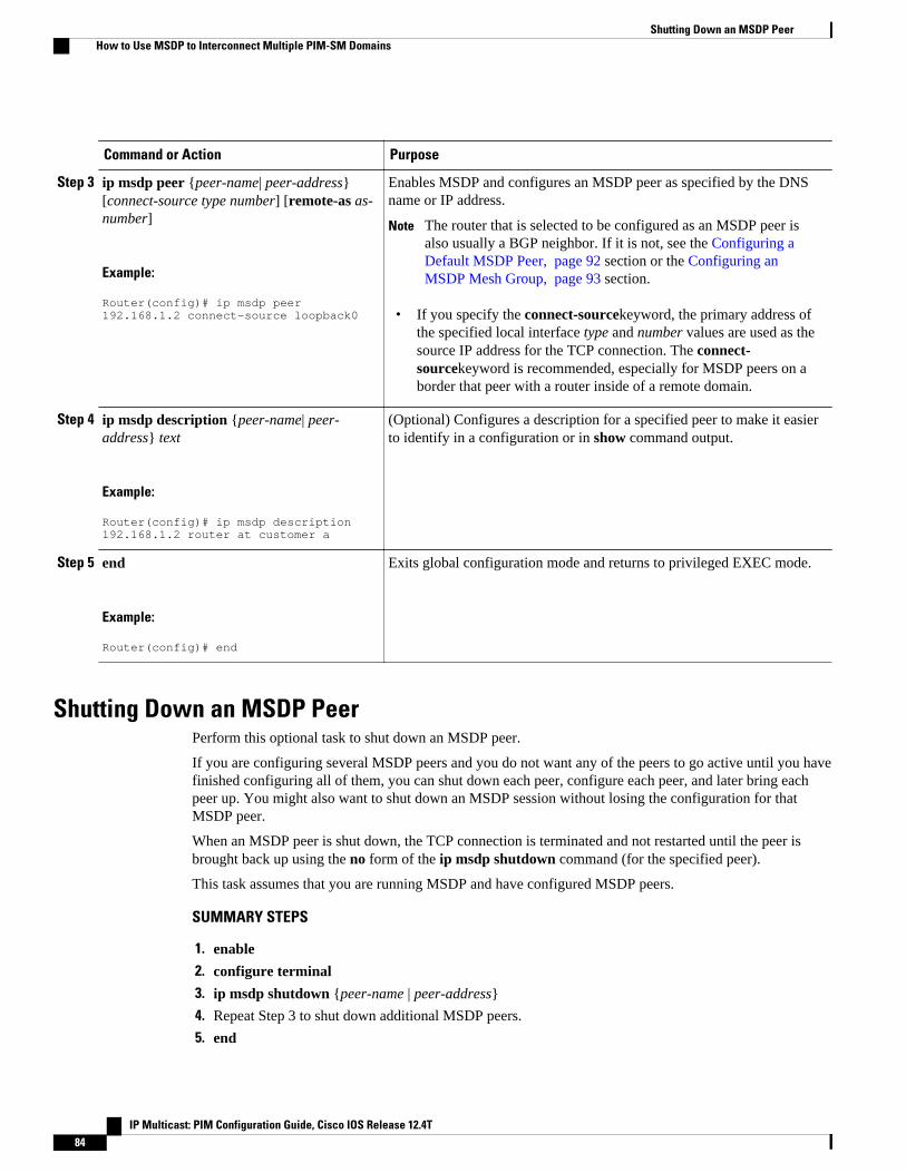
Command or Action Purpose
Step 3 ip msdp peer {peer-name| peer-address}[connect-source type number] [remote-as as-number]
Example:
Router(config)# ip msdp peer 192.168.1.2 connect-source loopback0
Enables MSDP and configures an MSDP peer as specified by the DNSname or IP address.
Note The router that is selected to be configured as an MSDP peer isalso usually a BGP neighbor. If it is not, see the Configuring aDefault MSDP Peer, page 92 section or the Configuring anMSDP Mesh Group, page 93 section.
• If you specify the connect-sourcekeyword, the primary address ofthe specified local interface type and number values are used as thesource IP address for the TCP connection. The connect-sourcekeyword is recommended, especially for MSDP peers on aborder that peer with a router inside of a remote domain.
Step 4 ip msdp description {peer-name| peer-address} text
Example:
Router(config)# ip msdp description 192.168.1.2 router at customer a
(Optional) Configures a description for a specified peer to make it easierto identify in a configuration or in show command output.
Step 5 end
Example:
Router(config)# end
Exits global configuration mode and returns to privileged EXEC mode.
Shutting Down an MSDP PeerPerform this optional task to shut down an MSDP peer.
If you are configuring several MSDP peers and you do not want any of the peers to go active until you havefinished configuring all of them, you can shut down each peer, configure each peer, and later bring eachpeer up. You might also want to shut down an MSDP session without losing the configuration for thatMSDP peer.
When an MSDP peer is shut down, the TCP connection is terminated and not restarted until the peer isbrought back up using the no form of the ip msdp shutdown command (for the specified peer).
This task assumes that you are running MSDP and have configured MSDP peers.
SUMMARY STEPS
1. enable
2. configure terminal
3. ip msdp shutdown {peer-name | peer-address}
4. Repeat Step 3 to shut down additional MSDP peers.
5. end
Shutting Down an MSDP Peer How to Use MSDP to Interconnect Multiple PIM-SM Domains
IP Multicast: PIM Configuration Guide, Cisco IOS Release 12.4T84
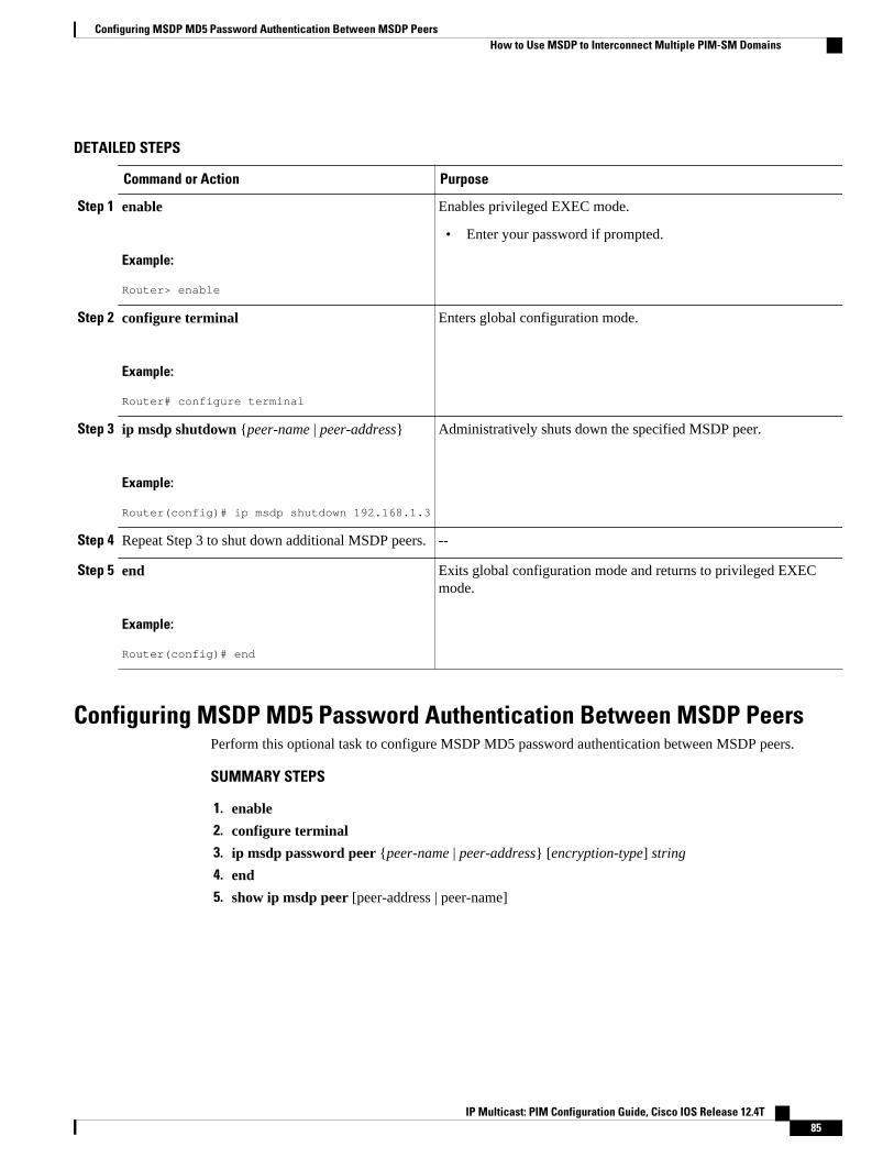
DETAILED STEPS
Command or Action Purpose
Step 1 enable
Example:
Router> enable
Enables privileged EXEC mode.
• Enter your password if prompted.
Step 2 configure terminal
Example:
Router# configure terminal
Enters global configuration mode.
Step 3 ip msdp shutdown {peer-name | peer-address}
Example:
Router(config)# ip msdp shutdown 192.168.1.3
Administratively shuts down the specified MSDP peer.
Step 4 Repeat Step 3 to shut down additional MSDP peers. --
Step 5 end
Example:
Router(config)# end
Exits global configuration mode and returns to privileged EXECmode.
Configuring MSDP MD5 Password Authentication Between MSDP PeersPerform this optional task to configure MSDP MD5 password authentication between MSDP peers.
SUMMARY STEPS
1. enable
2. configure terminal
3. ip msdp password peer {peer-name | peer-address} [encryption-type] string
4. end
5. show ip msdp peer [peer-address | peer-name]
Configuring MSDP MD5 Password Authentication Between MSDP PeersHow to Use MSDP to Interconnect Multiple PIM-SM Domains
IP Multicast: PIM Configuration Guide, Cisco IOS Release 12.4T 85
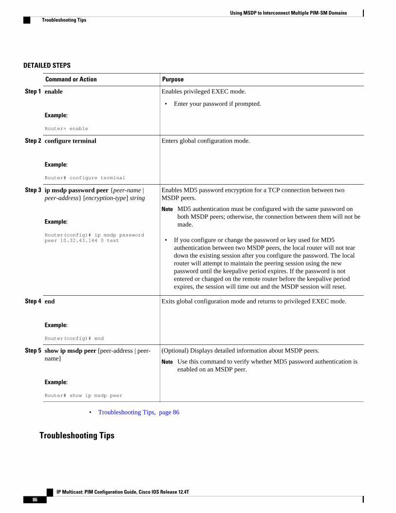
DETAILED STEPS
Command or Action Purpose
Step 1 enable
Example:
Router> enable
Enables privileged EXEC mode.
• Enter your password if prompted.
Step 2 configure terminal
Example:
Router# configure terminal
Enters global configuration mode.
Step 3 ip msdp password peer {peer-name |peer-address} [encryption-type] string
Example:
Router(config)# ip msdp password peer 10.32.43.144 0 test
Enables MD5 password encryption for a TCP connection between twoMSDP peers.
Note MD5 authentication must be configured with the same password onboth MSDP peers; otherwise, the connection between them will not bemade.
• If you configure or change the password or key used for MD5authentication between two MSDP peers, the local router will not teardown the existing session after you configure the password. The localrouter will attempt to maintain the peering session using the newpassword until the keepalive period expires. If the password is notentered or changed on the remote router before the keepalive periodexpires, the session will time out and the MSDP session will reset.
Step 4 end
Example:
Router(config)# end
Exits global configuration mode and returns to privileged EXEC mode.
Step 5 show ip msdp peer [peer-address | peer-name]
Example:
Router# show ip msdp peer
(Optional) Displays detailed information about MSDP peers.
Note Use this command to verify whether MD5 password authentication isenabled on an MSDP peer.
• Troubleshooting Tips, page 86
Troubleshooting Tips
Using MSDP to Interconnect Multiple PIM-SM Domains Troubleshooting Tips
IP Multicast: PIM Configuration Guide, Cisco IOS Release 12.4T86
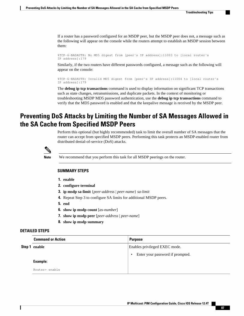
If a router has a password configured for an MSDP peer, but the MSDP peer does not, a message such asthe following will appear on the console while the routers attempt to establish an MSDP session betweenthem:
%TCP-6-BADAUTH: No MD5 digest from [peer's IP address]:11003 to [local router's IP address]:179
Similarly, if the two routers have different passwords configured, a message such as the following willappear on the console:
%TCP-6-BADAUTH: Invalid MD5 digest from [peer's IP address]:11004 to [local router's IP address]:179
The debug ip tcp transactions command is used to display information on significant TCP transactionssuch as state changes, retransmissions, and duplicate packets. In the context of monitoring ortroubleshooting MSDP MD5 password authentication, use the debug ip tcp transactions command toverify that the MD5 password is enabled and that the keepalive message is received by the MSDP peer.
Preventing DoS Attacks by Limiting the Number of SA Messages Allowed inthe SA Cache from Specified MSDP Peers
Perform this optional (but highly recommended) task to limit the overall number of SA messages that therouter can accept from specified MSDP peers. Performing this task protects an MSDP-enabled router fromdistributed denial-of-service (DoS) attacks.
Note We recommend that you perform this task for all MSDP peerings on the router.
SUMMARY STEPS
1. enable
2. configure terminal
3. ip msdp sa-limit {peer-address | peer-name} sa-limit
4. Repeat Step 3 to configure SA limits for additional MSDP peers.
5. end
6. show ip msdp count [as-number]
7. show ip msdp peer [peer-address | peer-name]
8. show ip msdp summary
DETAILED STEPS
Command or Action Purpose
Step 1 enable
Example:
Router> enable
Enables privileged EXEC mode.
• Enter your password if prompted.
Preventing DoS Attacks by Limiting the Number of SA Messages Allowed in the SA Cache from Specified MSDP PeersTroubleshooting Tips
IP Multicast: PIM Configuration Guide, Cisco IOS Release 12.4T 87
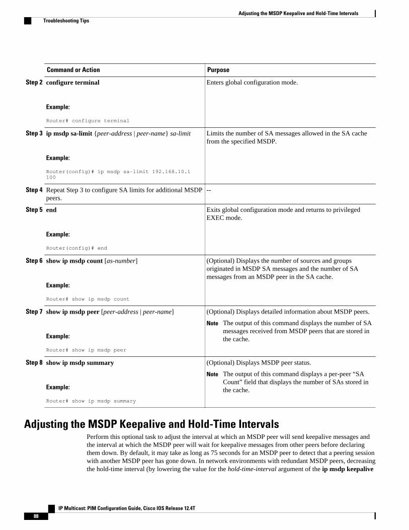
Command or Action Purpose
Step 2 configure terminal
Example:
Router# configure terminal
Enters global configuration mode.
Step 3 ip msdp sa-limit {peer-address | peer-name} sa-limit
Example:
Router(config)# ip msdp sa-limit 192.168.10.1 100
Limits the number of SA messages allowed in the SA cachefrom the specified MSDP.
Step 4 Repeat Step 3 to configure SA limits for additional MSDPpeers.
--
Step 5 end
Example:
Router(config)# end
Exits global configuration mode and returns to privilegedEXEC mode.
Step 6 show ip msdp count [as-number]
Example:
Router# show ip msdp count
(Optional) Displays the number of sources and groupsoriginated in MSDP SA messages and the number of SAmessages from an MSDP peer in the SA cache.
Step 7 show ip msdp peer [peer-address | peer-name]
Example:
Router# show ip msdp peer
(Optional) Displays detailed information about MSDP peers.
Note The output of this command displays the number of SAmessages received from MSDP peers that are stored inthe cache.
Step 8 show ip msdp summary
Example:
Router# show ip msdp summary
(Optional) Displays MSDP peer status.
Note The output of this command displays a per-peer “SACount” field that displays the number of SAs stored inthe cache.
Adjusting the MSDP Keepalive and Hold-Time IntervalsPerform this optional task to adjust the interval at which an MSDP peer will send keepalive messages andthe interval at which the MSDP peer will wait for keepalive messages from other peers before declaringthem down. By default, it may take as long as 75 seconds for an MSDP peer to detect that a peering sessionwith another MSDP peer has gone down. In network environments with redundant MSDP peers, decreasingthe hold-time interval (by lowering the value for the hold-time-interval argument of the ip msdp keepalive
Adjusting the MSDP Keepalive and Hold-Time Intervals Troubleshooting Tips
IP Multicast: PIM Configuration Guide, Cisco IOS Release 12.4T88
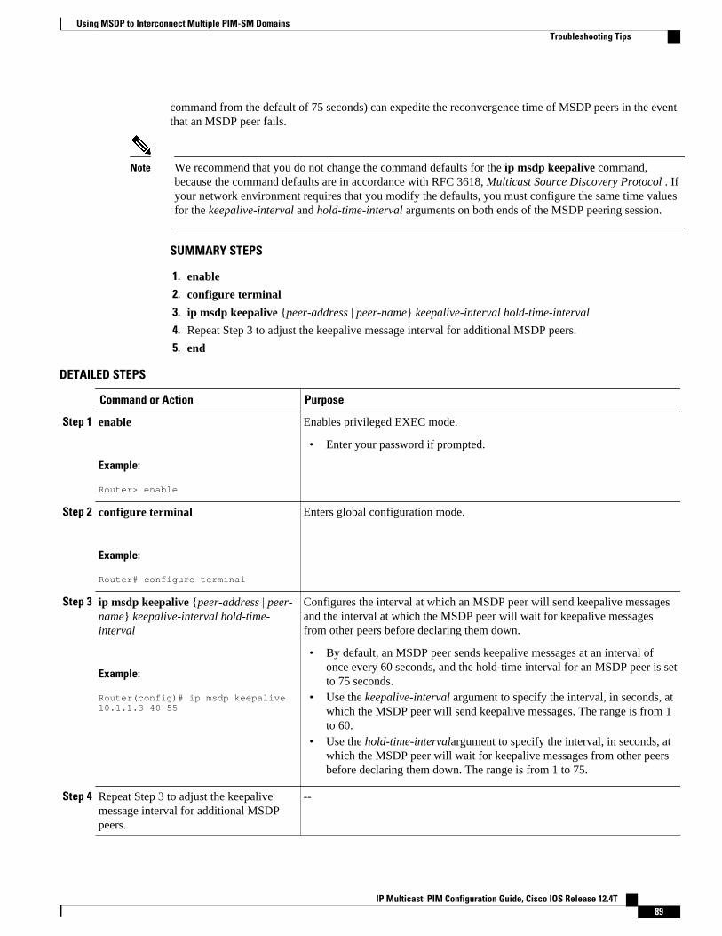
command from the default of 75 seconds) can expedite the reconvergence time of MSDP peers in the eventthat an MSDP peer fails.
Note We recommend that you do not change the command defaults for the ip msdp keepalive command,because the command defaults are in accordance with RFC 3618, Multicast Source Discovery Protocol . Ifyour network environment requires that you modify the defaults, you must configure the same time valuesfor the keepalive-interval and hold-time-interval arguments on both ends of the MSDP peering session.
SUMMARY STEPS
1. enable
2. configure terminal
3. ip msdp keepalive {peer-address | peer-name} keepalive-interval hold-time-interval
4. Repeat Step 3 to adjust the keepalive message interval for additional MSDP peers.
5. end
DETAILED STEPS
Command or Action Purpose
Step 1 enable
Example:
Router> enable
Enables privileged EXEC mode.
• Enter your password if prompted.
Step 2 configure terminal
Example:
Router# configure terminal
Enters global configuration mode.
Step 3 ip msdp keepalive {peer-address | peer-name} keepalive-interval hold-time-interval
Example:
Router(config)# ip msdp keepalive 10.1.1.3 40 55
Configures the interval at which an MSDP peer will send keepalive messagesand the interval at which the MSDP peer will wait for keepalive messagesfrom other peers before declaring them down.
• By default, an MSDP peer sends keepalive messages at an interval ofonce every 60 seconds, and the hold-time interval for an MSDP peer is setto 75 seconds.
• Use the keepalive-interval argument to specify the interval, in seconds, atwhich the MSDP peer will send keepalive messages. The range is from 1to 60.
• Use the hold-time-intervalargument to specify the interval, in seconds, atwhich the MSDP peer will wait for keepalive messages from other peersbefore declaring them down. The range is from 1 to 75.
Step 4 Repeat Step 3 to adjust the keepalivemessage interval for additional MSDPpeers.
--
Using MSDP to Interconnect Multiple PIM-SM DomainsTroubleshooting Tips
IP Multicast: PIM Configuration Guide, Cisco IOS Release 12.4T 89
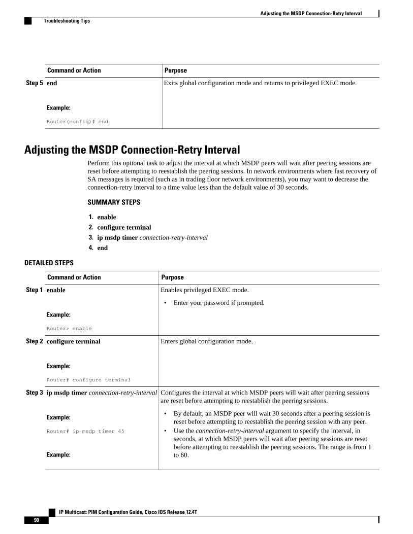
Command or Action Purpose
Step 5 end
Example:
Router(config)# end
Exits global configuration mode and returns to privileged EXEC mode.
Adjusting the MSDP Connection-Retry IntervalPerform this optional task to adjust the interval at which MSDP peers will wait after peering sessions arereset before attempting to reestablish the peering sessions. In network environments where fast recovery ofSA messages is required (such as in trading floor network environments), you may want to decrease theconnection-retry interval to a time value less than the default value of 30 seconds.
SUMMARY STEPS
1. enable
2. configure terminal
3. ip msdp timer connection-retry-interval
4. end
DETAILED STEPS
Command or Action Purpose
Step 1 enable
Example:
Router> enable
Enables privileged EXEC mode.
• Enter your password if prompted.
Step 2 configure terminal
Example:
Router# configure terminal
Enters global configuration mode.
Step 3 ip msdp timer connection-retry-interval
Example:
Router# ip msdp timer 45
Example:
Configures the interval at which MSDP peers will wait after peering sessionsare reset before attempting to reestablish the peering sessions.
• By default, an MSDP peer will wait 30 seconds after a peering session isreset before attempting to reestablish the peering session with any peer.
• Use the connection-retry-interval argument to specify the interval, inseconds, at which MSDP peers will wait after peering sessions are resetbefore attempting to reestablish the peering sessions. The range is from 1to 60.
Adjusting the MSDP Connection-Retry Interval Troubleshooting Tips
IP Multicast: PIM Configuration Guide, Cisco IOS Release 12.4T90
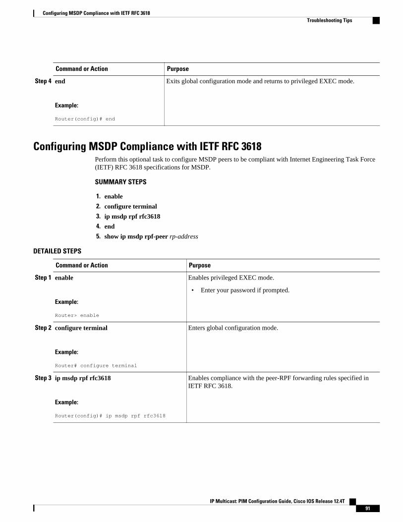
Command or Action Purpose
Step 4 end
Example:
Router(config)# end
Exits global configuration mode and returns to privileged EXEC mode.
Configuring MSDP Compliance with IETF RFC 3618Perform this optional task to configure MSDP peers to be compliant with Internet Engineering Task Force(IETF) RFC 3618 specifications for MSDP.
SUMMARY STEPS
1. enable
2. configure terminal
3. ip msdp rpf rfc3618
4. end
5. show ip msdp rpf-peer rp-address
DETAILED STEPS
Command or Action Purpose
Step 1 enable
Example:
Router> enable
Enables privileged EXEC mode.
• Enter your password if prompted.
Step 2 configure terminal
Example:
Router# configure terminal
Enters global configuration mode.
Step 3 ip msdp rpf rfc3618
Example:
Router(config)# ip msdp rpf rfc3618
Enables compliance with the peer-RPF forwarding rules specified inIETF RFC 3618.
Configuring MSDP Compliance with IETF RFC 3618Troubleshooting Tips
IP Multicast: PIM Configuration Guide, Cisco IOS Release 12.4T 91
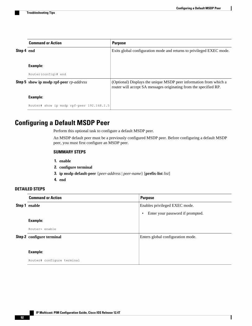
Command or Action Purpose
Step 4 end
Example:
Router(config)# end
Exits global configuration mode and returns to privileged EXEC mode.
Step 5 show ip msdp rpf-peer rp-address
Example:
Router# show ip msdp rpf-peer 192.168.1.5
(Optional) Displays the unique MSDP peer information from which arouter will accept SA messages originating from the specified RP.
Configuring a Default MSDP PeerPerform this optional task to configure a default MSDP peer.
An MSDP default peer must be a previously configured MSDP peer. Before configuring a default MSDPpeer, you must first configure an MSDP peer.
SUMMARY STEPS
1. enable
2. configure terminal
3. ip msdp default-peer {peer-address | peer-name} [prefix-list list]
4. end
DETAILED STEPS
Command or Action Purpose
Step 1 enable
Example:
Router> enable
Enables privileged EXEC mode.
• Enter your password if prompted.
Step 2 configure terminal
Example:
Router# configure terminal
Enters global configuration mode.
Configuring a Default MSDP Peer Troubleshooting Tips
IP Multicast: PIM Configuration Guide, Cisco IOS Release 12.4T92
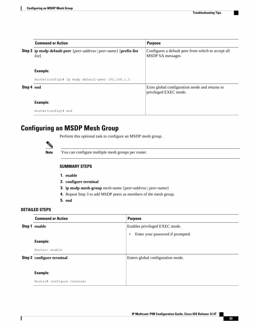
Command or Action Purpose
Step 3 ip msdp default-peer {peer-address | peer-name} [prefix-listlist]
Example:
Router(config)# ip msdp default-peer 192.168.1.3
Configures a default peer from which to accept allMSDP SA messages
Step 4 end
Example:
Router(config)# end
Exits global configuration mode and returns toprivileged EXEC mode.
Configuring an MSDP Mesh GroupPerform this optional task to configure an MSDP mesh group.
Note You can configure multiple mesh groups per router.
SUMMARY STEPS
1. enable
2. configure terminal
3. ip msdp mesh-group mesh-name {peer-address | peer-name}
4. Repeat Step 3 to add MSDP peers as members of the mesh group.
5. end
DETAILED STEPS
Command or Action Purpose
Step 1 enable
Example:
Router> enable
Enables privileged EXEC mode.
• Enter your password if prompted.
Step 2 configure terminal
Example:
Router# configure terminal
Enters global configuration mode.
Configuring an MSDP Mesh GroupTroubleshooting Tips
IP Multicast: PIM Configuration Guide, Cisco IOS Release 12.4T 93
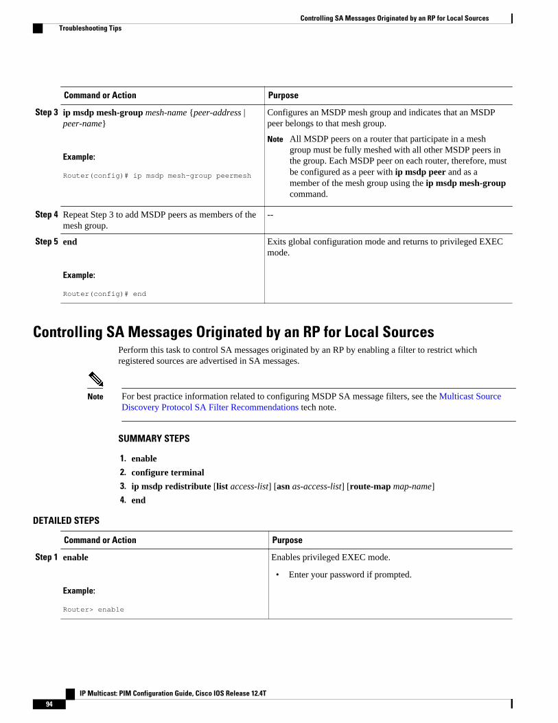
Command or Action Purpose
Step 3 ip msdp mesh-group mesh-name {peer-address |peer-name}
Example:
Router(config)# ip msdp mesh-group peermesh
Configures an MSDP mesh group and indicates that an MSDPpeer belongs to that mesh group.
Note All MSDP peers on a router that participate in a meshgroup must be fully meshed with all other MSDP peers inthe group. Each MSDP peer on each router, therefore, mustbe configured as a peer with ip msdp peer and as amember of the mesh group using the ip msdp mesh-groupcommand.
Step 4 Repeat Step 3 to add MSDP peers as members of themesh group.
--
Step 5 end
Example:
Router(config)# end
Exits global configuration mode and returns to privileged EXECmode.
Controlling SA Messages Originated by an RP for Local SourcesPerform this task to control SA messages originated by an RP by enabling a filter to restrict whichregistered sources are advertised in SA messages.
Note For best practice information related to configuring MSDP SA message filters, see the Multicast SourceDiscovery Protocol SA Filter Recommendations tech note.
SUMMARY STEPS
1. enable
2. configure terminal
3. ip msdp redistribute [list access-list] [asn as-access-list] [route-map map-name]
4. end
DETAILED STEPS
Command or Action Purpose
Step 1 enable
Example:
Router> enable
Enables privileged EXEC mode.
• Enter your password if prompted.
Controlling SA Messages Originated by an RP for Local Sources Troubleshooting Tips
IP Multicast: PIM Configuration Guide, Cisco IOS Release 12.4T94
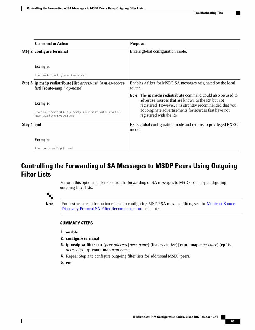
Command or Action Purpose
Step 2 configure terminal
Example:
Router# configure terminal
Enters global configuration mode.
Step 3 ip msdp redistribute [list access-list] [asn as-access-list] [route-map map-name]
Example:
Router(config)# ip msdp redistribute route-map customer-sources
Enables a filter for MSDP SA messages originated by the localrouter.
Note The ip msdp redistribute command could also be used toadvertise sources that are known to the RP but notregistered. However, it is strongly recommended that younot originate advertisements for sources that have notregistered with the RP.
Step 4 end
Example:
Router(config)# end
Exits global configuration mode and returns to privileged EXECmode.
Controlling the Forwarding of SA Messages to MSDP Peers Using OutgoingFilter Lists
Perform this optional task to control the forwarding of SA messages to MSDP peers by configuringoutgoing filter lists.
Note For best practice information related to configuring MSDP SA message filters, see the Multicast SourceDiscovery Protocol SA Filter Recommendations tech note.
SUMMARY STEPS
1. enable
2. configure terminal
3. ip msdp sa-filter out {peer-address | peer-name} [list access-list] [route-map map-name] [rp-listaccess-list | rp-route-map map-name]
4. Repeat Step 3 to configure outgoing filter lists for additional MSDP peers.
5. end
Controlling the Forwarding of SA Messages to MSDP Peers Using Outgoing Filter ListsTroubleshooting Tips
IP Multicast: PIM Configuration Guide, Cisco IOS Release 12.4T 95
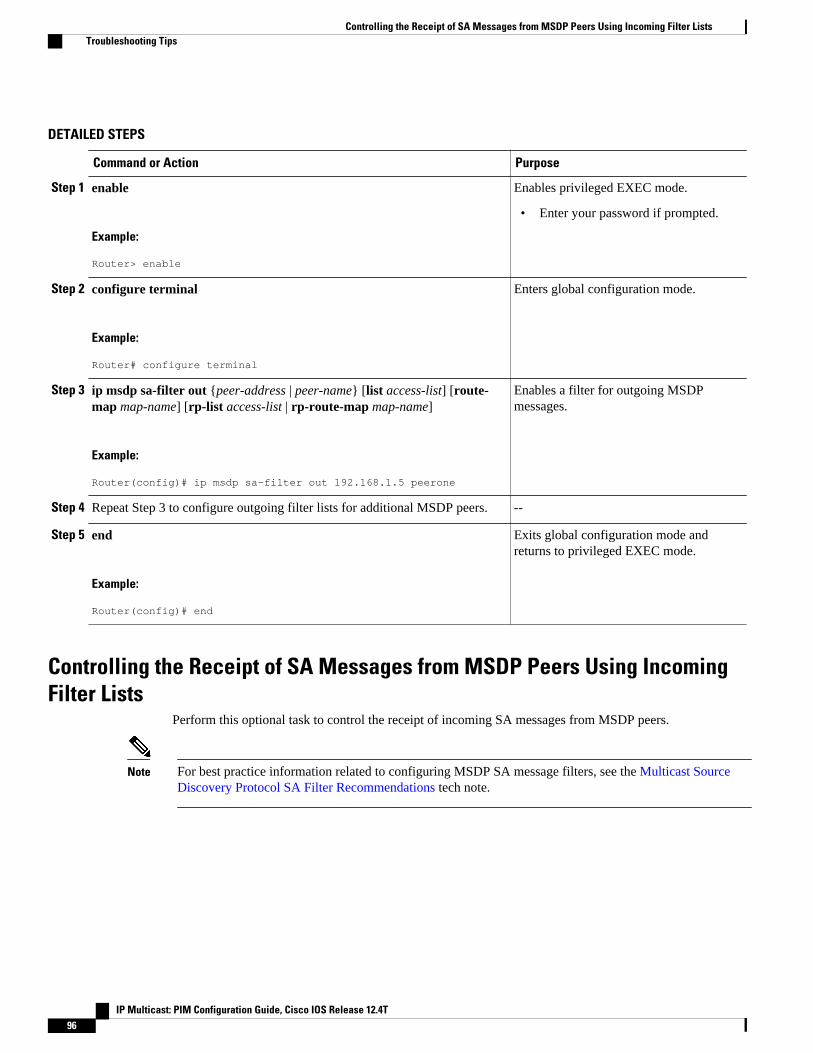
DETAILED STEPS
Command or Action Purpose
Step 1 enable
Example:
Router> enable
Enables privileged EXEC mode.
• Enter your password if prompted.
Step 2 configure terminal
Example:
Router# configure terminal
Enters global configuration mode.
Step 3 ip msdp sa-filter out {peer-address | peer-name} [list access-list] [route-map map-name] [rp-list access-list | rp-route-map map-name]
Example:
Router(config)# ip msdp sa-filter out 192.168.1.5 peerone
Enables a filter for outgoing MSDPmessages.
Step 4 Repeat Step 3 to configure outgoing filter lists for additional MSDP peers. --
Step 5 end
Example:
Router(config)# end
Exits global configuration mode andreturns to privileged EXEC mode.
Controlling the Receipt of SA Messages from MSDP Peers Using IncomingFilter Lists
Perform this optional task to control the receipt of incoming SA messages from MSDP peers.
Note For best practice information related to configuring MSDP SA message filters, see the Multicast SourceDiscovery Protocol SA Filter Recommendations tech note.
Controlling the Receipt of SA Messages from MSDP Peers Using Incoming Filter Lists Troubleshooting Tips
IP Multicast: PIM Configuration Guide, Cisco IOS Release 12.4T96
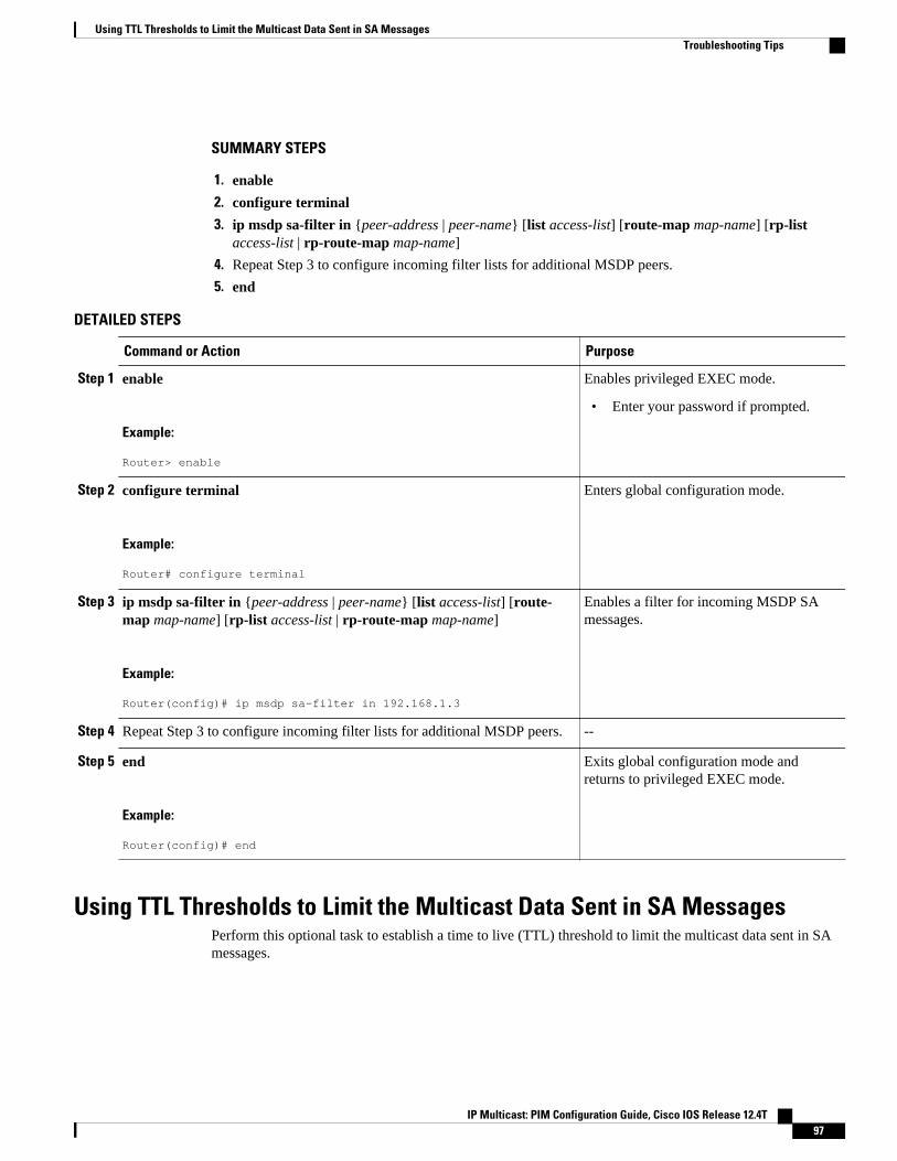
SUMMARY STEPS
1. enable
2. configure terminal
3. ip msdp sa-filter in {peer-address | peer-name} [list access-list] [route-map map-name] [rp-listaccess-list | rp-route-map map-name]
4. Repeat Step 3 to configure incoming filter lists for additional MSDP peers.
5. end
DETAILED STEPS
Command or Action Purpose
Step 1 enable
Example:
Router> enable
Enables privileged EXEC mode.
• Enter your password if prompted.
Step 2 configure terminal
Example:
Router# configure terminal
Enters global configuration mode.
Step 3 ip msdp sa-filter in {peer-address | peer-name} [list access-list] [route-map map-name] [rp-list access-list | rp-route-map map-name]
Example:
Router(config)# ip msdp sa-filter in 192.168.1.3
Enables a filter for incoming MSDP SAmessages.
Step 4 Repeat Step 3 to configure incoming filter lists for additional MSDP peers. --
Step 5 end
Example:
Router(config)# end
Exits global configuration mode andreturns to privileged EXEC mode.
Using TTL Thresholds to Limit the Multicast Data Sent in SA MessagesPerform this optional task to establish a time to live (TTL) threshold to limit the multicast data sent in SAmessages.
Using TTL Thresholds to Limit the Multicast Data Sent in SA MessagesTroubleshooting Tips
IP Multicast: PIM Configuration Guide, Cisco IOS Release 12.4T 97
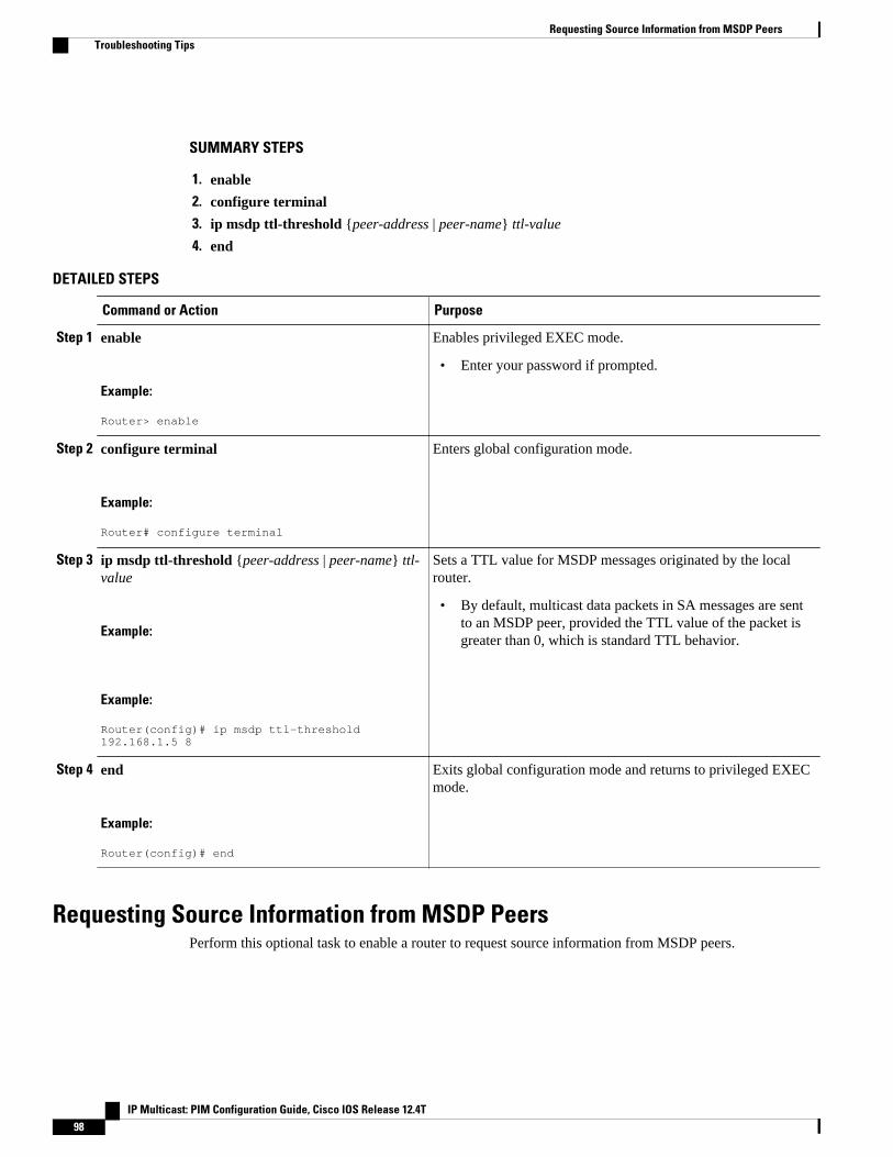
SUMMARY STEPS
1. enable
2. configure terminal
3. ip msdp ttl-threshold {peer-address | peer-name} ttl-value
4. end
DETAILED STEPS
Command or Action Purpose
Step 1 enable
Example:
Router> enable
Enables privileged EXEC mode.
• Enter your password if prompted.
Step 2 configure terminal
Example:
Router# configure terminal
Enters global configuration mode.
Step 3 ip msdp ttl-threshold {peer-address | peer-name} ttl-value
Example:
Example:
Router(config)# ip msdp ttl-threshold 192.168.1.5 8
Sets a TTL value for MSDP messages originated by the localrouter.
• By default, multicast data packets in SA messages are sentto an MSDP peer, provided the TTL value of the packet isgreater than 0, which is standard TTL behavior.
Step 4 end
Example:
Router(config)# end
Exits global configuration mode and returns to privileged EXECmode.
Requesting Source Information from MSDP PeersPerform this optional task to enable a router to request source information from MSDP peers.
Requesting Source Information from MSDP Peers Troubleshooting Tips
IP Multicast: PIM Configuration Guide, Cisco IOS Release 12.4T98
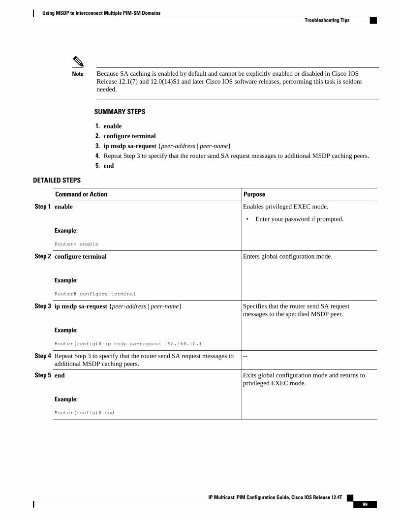
Note Because SA caching is enabled by default and cannot be explicitly enabled or disabled in Cisco IOSRelease 12.1(7) and 12.0(14)S1 and later Cisco IOS software releases, performing this task is seldomneeded.
SUMMARY STEPS
1. enable
2. configure terminal
3. ip msdp sa-request {peer-address | peer-name}
4. Repeat Step 3 to specify that the router send SA request messages to additional MSDP caching peers.
5. end
DETAILED STEPS
Command or Action Purpose
Step 1 enable
Example:
Router> enable
Enables privileged EXEC mode.
• Enter your password if prompted.
Step 2 configure terminal
Example:
Router# configure terminal
Enters global configuration mode.
Step 3 ip msdp sa-request {peer-address | peer-name}
Example:
Router(config)# ip msdp sa-request 192.168.10.1
Specifies that the router send SA requestmessages to the specified MSDP peer.
Step 4 Repeat Step 3 to specify that the router send SA request messages toadditional MSDP caching peers.
--
Step 5 end
Example:
Router(config)# end
Exits global configuration mode and returns toprivileged EXEC mode.
Using MSDP to Interconnect Multiple PIM-SM DomainsTroubleshooting Tips
IP Multicast: PIM Configuration Guide, Cisco IOS Release 12.4T 99
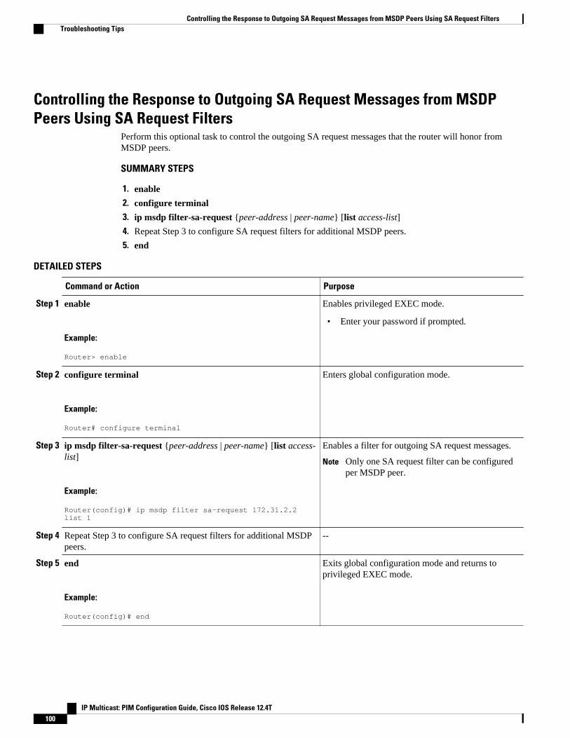
Controlling the Response to Outgoing SA Request Messages from MSDPPeers Using SA Request Filters
Perform this optional task to control the outgoing SA request messages that the router will honor fromMSDP peers.
SUMMARY STEPS
1. enable
2. configure terminal
3. ip msdp filter-sa-request {peer-address | peer-name} [list access-list]
4. Repeat Step 3 to configure SA request filters for additional MSDP peers.
5. end
DETAILED STEPS
Command or Action Purpose
Step 1 enable
Example:
Router> enable
Enables privileged EXEC mode.
• Enter your password if prompted.
Step 2 configure terminal
Example:
Router# configure terminal
Enters global configuration mode.
Step 3 ip msdp filter-sa-request {peer-address | peer-name} [list access-list]
Example:
Router(config)# ip msdp filter sa-request 172.31.2.2 list 1
Enables a filter for outgoing SA request messages.
Note Only one SA request filter can be configuredper MSDP peer.
Step 4 Repeat Step 3 to configure SA request filters for additional MSDPpeers.
--
Step 5 end
Example:
Router(config)# end
Exits global configuration mode and returns toprivileged EXEC mode.
Controlling the Response to Outgoing SA Request Messages from MSDP Peers Using SA Request Filters Troubleshooting Tips
IP Multicast: PIM Configuration Guide, Cisco IOS Release 12.4T100
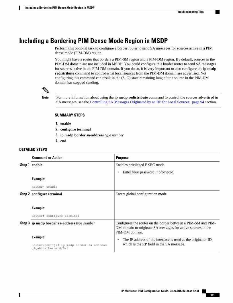
Including a Bordering PIM Dense Mode Region in MSDPPerform this optional task to configure a border router to send SA messages for sources active in a PIMdense mode (PIM-DM) region.
You might have a router that borders a PIM-SM region and a PIM-DM region. By default, sources in thePIM-DM domain are not included in MSDP. You could configure this border router to send SA messagesfor sources active in the PIM-DM domain. If you do so, it is very important to also configure the ip msdpredistribute command to control what local sources from the PIM-DM domain are advertised. Notconfiguring this command can result in the (S, G) state remaining long after a source in the PIM-DMdomain has stopped sending.
Note For more information about using the ip msdp redistribute command to control the sources advertised inSA messages, see the Controlling SA Messages Originated by an RP for Local Sources, page 94 section.
SUMMARY STEPS
1. enable
2. configure terminal
3. ip msdp border sa-address type number
4. end
DETAILED STEPS
Command or Action Purpose
Step 1 enable
Example:
Router> enable
Enables privileged EXEC mode.
• Enter your password if prompted.
Step 2 configure terminal
Example:
Router# configure terminal
Enters global configuration mode.
Step 3 ip msdp border sa-address type number
Example:
Router(config)# ip msdp border sa-address gigabitethernet0/0/0
Configures the router on the border between a PIM-SM and PIM-DM domain to originate SA messages for active sources in thePIM-DM domain.
• The IP address of the interface is used as the originator ID,which is the RP field in the SA message.
Including a Bordering PIM Dense Mode Region in MSDPTroubleshooting Tips
IP Multicast: PIM Configuration Guide, Cisco IOS Release 12.4T 101
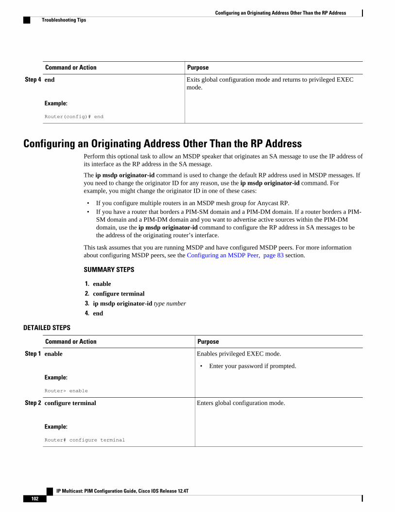
Command or Action Purpose
Step 4 end
Example:
Router(config)# end
Exits global configuration mode and returns to privileged EXECmode.
Configuring an Originating Address Other Than the RP AddressPerform this optional task to allow an MSDP speaker that originates an SA message to use the IP address ofits interface as the RP address in the SA message.
The ip msdp originator-id command is used to change the default RP address used in MSDP messages. Ifyou need to change the originator ID for any reason, use the ip msdp originator-id command. Forexample, you might change the originator ID in one of these cases:
• If you configure multiple routers in an MSDP mesh group for Anycast RP.• If you have a router that borders a PIM-SM domain and a PIM-DM domain. If a router borders a PIM-
SM domain and a PIM-DM domain and you want to advertise active sources within the PIM-DMdomain, use the ip msdp originator-id command to configure the RP address in SA messages to bethe address of the originating router’s interface.
This task assumes that you are running MSDP and have configured MSDP peers. For more informationabout configuring MSDP peers, see the Configuring an MSDP Peer, page 83 section.
SUMMARY STEPS
1. enable
2. configure terminal
3. ip msdp originator-id type number
4. end
DETAILED STEPS
Command or Action Purpose
Step 1 enable
Example:
Router> enable
Enables privileged EXEC mode.
• Enter your password if prompted.
Step 2 configure terminal
Example:
Router# configure terminal
Enters global configuration mode.
Configuring an Originating Address Other Than the RP Address Troubleshooting Tips
IP Multicast: PIM Configuration Guide, Cisco IOS Release 12.4T102

Command or Action Purpose
Step 3 ip msdp originator-id type number
Example:
Router(config)# ip msdp originator-id ethernet 1
Configures the RP address in SA messages to be the address ofthe originating router’s interface.
Step 4 end
Example:
Router(config)# end
Exits global configuration mode and returns to privilegedEXEC mode.
Monitoring MSDPPerform this optional task to monitor MSDP SA messages, peers, state, and peer status.
SUMMARY STEPS
1. enable
2. debug ip msdp [peer-address | peer-name] [detail] [routes]
3. debug ip msdp resets
4. show ip msdp count [as-number]
5. show ip msdp peer [peer-address | peer-name]
6. show ip msdp sa-cache [group-address | source-address | group-name | source-name] [as-number]
7. show ip msdp summary
DETAILED STEPS
Step 1 enableUse this command to enable privileged EXEC mode. Enter your password if prompted.
Example:
Router# enable
Step 2 debug ip msdp [peer-address | peer-name] [detail] [routes]Use this command to debug MSDP activity.
Use the optional peer-address or peer-name argument to specify for which peer debug events are logged.
The following is sample output from the debug ip msdp command:
Example:
Router# debug ip msdpMSDP debugging is on
Monitoring MSDPTroubleshooting Tips
IP Multicast: PIM Configuration Guide, Cisco IOS Release 12.4T 103

Router#MSDP: 224.150.44.254: Received 1388-byte message from peerMSDP: 224.150.44.254: SA TLV, len: 1388, ec: 115, RP: 172.31.3.92 MSDP: 224.150.44.254: Peer RPF check passed for 172.31.3.92, used EMBGP peerMSDP: 224.150.44.250: Forward 1388-byte SA to peerMSDP: 224.150.44.254: Received 1028-byte message from peerMSDP: 224.150.44.254: SA TLV, len: 1028, ec: 85, RP: 172.31.3.92 MSDP: 224.150.44.254: Peer RPF check passed for 172.31.3.92, used EMBGP peerMSDP: 224.150.44.250: Forward 1028-byte SA to peerMSDP: 224.150.44.254: Received 1388-byte message from peerMSDP: 224.150.44.254: SA TLV, len: 1388, ec: 115, RP: 172.31.3.111 MSDP: 224.150.44.254: Peer RPF check passed for 172.31.3.111, used EMBGP peerMSDP: 224.150.44.250: Forward 1388-byte SA to peerMSDP: 224.150.44.250: Received 56-byte message from peerMSDP: 224.150.44.250: SA TLV, len: 56, ec: 4, RP: 192.168.76.241 MSDP: 224.150.44.250: Peer RPF check passed for 192.168.76.241, used EMBGP peerMSDP: 224.150.44.254: Forward 56-byte SA to peerMSDP: 224.150.44.254: Received 116-byte message from peerMSDP: 224.150.44.254: SA TLV, len: 116, ec: 9, RP: 172.31.3.111 MSDP: 224.150.44.254: Peer RPF check passed for 172.31.3.111, used EMBGP peerMSDP: 224.150.44.250: Forward 116-byte SA to peerMSDP: 224.150.44.254: Received 32-byte message from peerMSDP: 224.150.44.254: SA TLV, len: 32, ec: 2, RP: 172.31.3.78 MSDP: 224.150.44.254: Peer RPF check passed for 172.31.3.78, used EMBGP peerMSDP: 224.150.44.250: Forward 32-byte SA to peer
Step 3 debug ip msdp resetsUse this command to debug MSDP peer reset reasons.
Example:
Router# debug ip msdp resets
Step 4 show ip msdp count [as-number]Use this command to display the number of sources and groups originated in MSDP SA messages and the number ofSA messages from an MSDP peer in the SA cache. The ip msdp cache-sa-state command must be configured for thiscommand to produce any output.
The following is sample output from the show ip msdp countcommand:
Example:
Router# show ip msdp countSA State per Peer Counters, <Peer>: <# SA learned> 192.168.4.4: 8SA State per ASN Counters, <asn>: <# sources>/<# groups> Total entries: 8 ?: 8/8
Step 5 show ip msdp peer [peer-address | peer-name]Use this command to display detailed information about MSDP peers.
Use the optional peer-address or peer-name argument to display information about a particular peer.
The following is sample output from the show ip msdp peercommand:
Example:
Router# show ip msdp peer 192.168.4.4MSDP Peer 192.168.4.4 (?), AS 64512 (configured AS) Connection status: State: Up, Resets: 0, Connection source: Loopback0 (2.2.2.2) Uptime(Downtime): 00:07:55, Messages sent/received: 8/18 Output messages discarded: 0
Using MSDP to Interconnect Multiple PIM-SM Domains Troubleshooting Tips
IP Multicast: PIM Configuration Guide, Cisco IOS Release 12.4T104
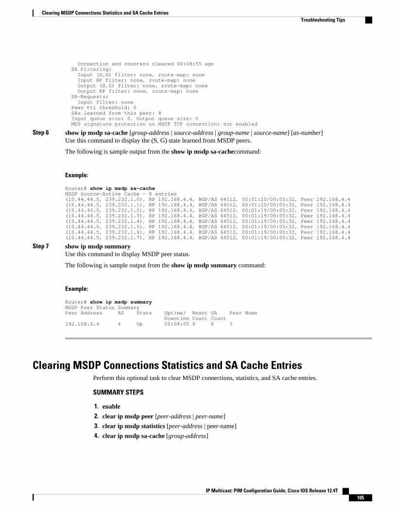
Connection and counters cleared 00:08:55 ago SA Filtering: Input (S,G) filter: none, route-map: none Input RP filter: none, route-map: none Output (S,G) filter: none, route-map: none Output RP filter: none, route-map: none SA-Requests: Input filter: none Peer ttl threshold: 0 SAs learned from this peer: 8 Input queue size: 0, Output queue size: 0 MD5 signature protection on MSDP TCP connection: not enabled
Step 6 show ip msdp sa-cache [group-address | source-address | group-name | source-name] [as-number]Use this command to display the (S, G) state learned from MSDP peers.
The following is sample output from the show ip msdp sa-cachecommand:
Example:
Router# show ip msdp sa-cacheMSDP Source-Active Cache - 8 entries(10.44.44.5, 239.232.1.0), RP 192.168.4.4, BGP/AS 64512, 00:01:20/00:05:32, Peer 192.168.4.4(10.44.44.5, 239.232.1.1), RP 192.168.4.4, BGP/AS 64512, 00:01:20/00:05:32, Peer 192.168.4.4(10.44.44.5, 239.232.1.2), RP 192.168.4.4, BGP/AS 64512, 00:01:19/00:05:32, Peer 192.168.4.4(10.44.44.5, 239.232.1.3), RP 192.168.4.4, BGP/AS 64512, 00:01:19/00:05:32, Peer 192.168.4.4(10.44.44.5, 239.232.1.4), RP 192.168.4.4, BGP/AS 64512, 00:01:19/00:05:32, Peer 192.168.4.4(10.44.44.5, 239.232.1.5), RP 192.168.4.4, BGP/AS 64512, 00:01:19/00:05:32, Peer 192.168.4.4(10.44.44.5, 239.232.1.6), RP 192.168.4.4, BGP/AS 64512, 00:01:19/00:05:32, Peer 192.168.4.4(10.44.44.5, 239.232.1.7), RP 192.168.4.4, BGP/AS 64512, 00:01:19/00:05:32, Peer 192.168.4.4
Step 7 show ip msdp summaryUse this command to display MSDP peer status.
The following is sample output from the show ip msdp summary command:
Example:
Router# show ip msdp summaryMSDP Peer Status SummaryPeer Address AS State Uptime/ Reset SA Peer Name Downtime Count Count192.168.4.4 4 Up 00:08:05 0 8 ?
Clearing MSDP Connections Statistics and SA Cache EntriesPerform this optional task to clear MSDP connections, statistics, and SA cache entries.
SUMMARY STEPS
1. enable
2. clear ip msdp peer [peer-address | peer-name]
3. clear ip msdp statistics [peer-address | peer-name]
4. clear ip msdp sa-cache [group-address]
Clearing MSDP Connections Statistics and SA Cache EntriesTroubleshooting Tips
IP Multicast: PIM Configuration Guide, Cisco IOS Release 12.4T 105
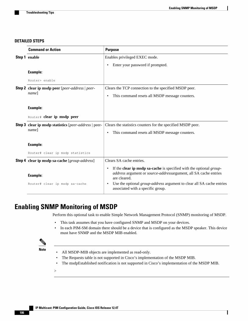
DETAILED STEPS
Command or Action Purpose
Step 1 enable
Example:
Router> enable
Enables privileged EXEC mode.
• Enter your password if prompted.
Step 2 clear ip msdp peer [peer-address | peer-name]
Example:
Router# clear ip msdp peer
Clears the TCP connection to the specified MSDP peer.
• This command resets all MSDP message counters.
Step 3 clear ip msdp statistics [peer-address | peer-name]
Example:
Router# clear ip msdp statistics
Clears the statistics counters for the specified MSDP peer.
• This command resets all MSDP message counters.
Step 4 clear ip msdp sa-cache [group-address]
Example:
Router# clear ip msdp sa-cache
Clears SA cache entries.
• If the clear ip msdp sa-cache is specified with the optional group-address argument or source-addressargument, all SA cache entriesare cleared.
• Use the optional group-address argument to clear all SA cache entriesassociated with a specific group.
Enabling SNMP Monitoring of MSDPPerform this optional task to enable Simple Network Management Protocol (SNMP) monitoring of MSDP.
• This task assumes that you have configured SNMP and MSDP on your devices.• In each PIM-SM domain there should be a device that is configured as the MSDP speaker. This device
must have SNMP and the MSDP MIB enabled.
Note• All MSDP-MIB objects are implemented as read-only.• The Requests table is not supported in Cisco’s implementation of the MSDP MIB.• The msdpEstablished notification is not supported in Cisco’s implementation of the MSDP MIB.
>
Enabling SNMP Monitoring of MSDP Troubleshooting Tips
IP Multicast: PIM Configuration Guide, Cisco IOS Release 12.4T106
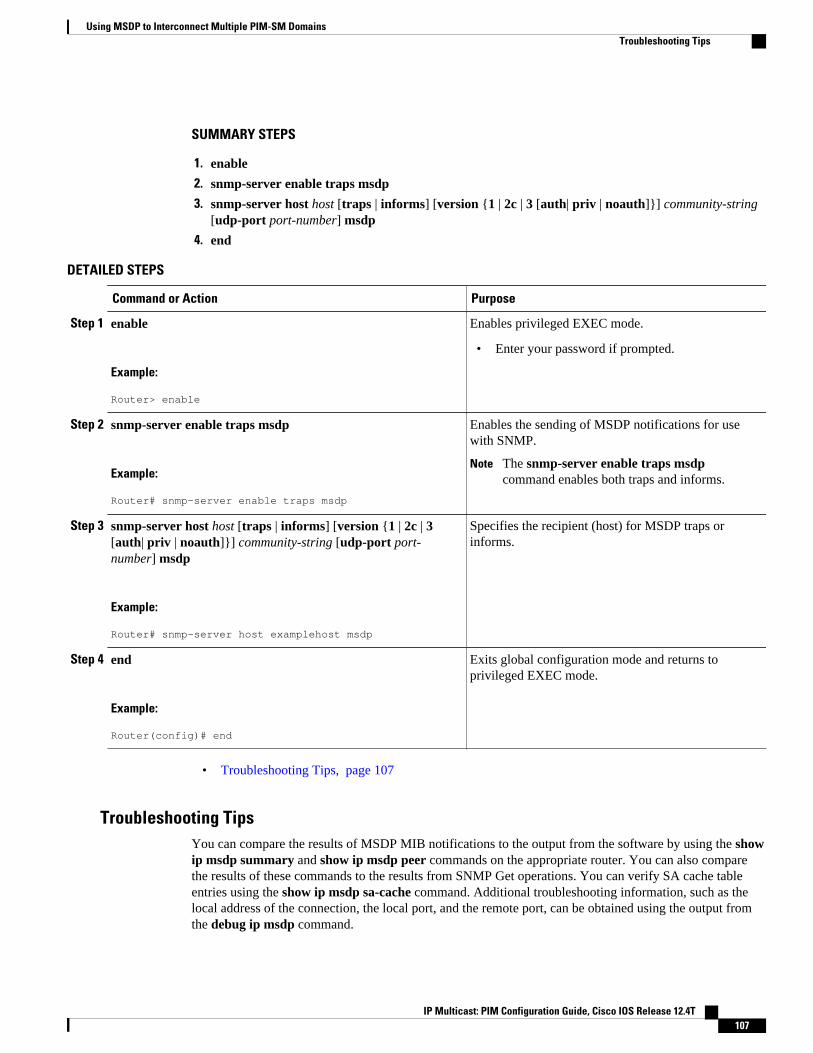
SUMMARY STEPS
1. enable
2. snmp-server enable traps msdp
3. snmp-server host host [traps | informs] [version {1 | 2c | 3 [auth| priv | noauth]}] community-string[udp-port port-number] msdp
4. end
DETAILED STEPS
Command or Action Purpose
Step 1 enable
Example:
Router> enable
Enables privileged EXEC mode.
• Enter your password if prompted.
Step 2 snmp-server enable traps msdp
Example:
Router# snmp-server enable traps msdp
Enables the sending of MSDP notifications for usewith SNMP.
Note The snmp-server enable traps msdpcommand enables both traps and informs.
Step 3 snmp-server host host [traps | informs] [version {1 | 2c | 3[auth| priv | noauth]}] community-string [udp-port port-number] msdp
Example:
Router# snmp-server host examplehost msdp
Specifies the recipient (host) for MSDP traps orinforms.
Step 4 end
Example:
Router(config)# end
Exits global configuration mode and returns toprivileged EXEC mode.
• Troubleshooting Tips, page 107
Troubleshooting TipsYou can compare the results of MSDP MIB notifications to the output from the software by using the showip msdp summary and show ip msdp peer commands on the appropriate router. You can also comparethe results of these commands to the results from SNMP Get operations. You can verify SA cache tableentries using the show ip msdp sa-cache command. Additional troubleshooting information, such as thelocal address of the connection, the local port, and the remote port, can be obtained using the output fromthe debug ip msdp command.
Using MSDP to Interconnect Multiple PIM-SM DomainsTroubleshooting Tips
IP Multicast: PIM Configuration Guide, Cisco IOS Release 12.4T 107
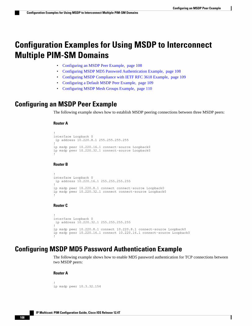
Configuration Examples for Using MSDP to InterconnectMultiple PIM-SM Domains
• Configuring an MSDP Peer Example, page 108
• Configuring MSDP MD5 Password Authentication Example, page 108
• Configuring MSDP Compliance with IETF RFC 3618 Example, page 109
• Configuring a Default MSDP Peer Example, page 109
• Configuring MSDP Mesh Groups Example, page 110
Configuring an MSDP Peer ExampleThe following example shows how to establish MSDP peering connections between three MSDP peers:
Router A
!interface Loopback 0 ip address 10.220.8.1 255.255.255.255!ip msdp peer 10.220.16.1 connect-source Loopback0ip msdp peer 10.220.32.1 connect-source Loopback0!
Router B
!interface Loopback 0 ip address 10.220.16.1 255.255.255.255!ip msdp peer 10.220.8.1 connect connect-source Loopback0 ip msdp peer 10.220.32.1 connect connect-source Loopback0!
Router C
!interface Loopback 0 ip address 10.220.32.1 255.255.255.255!ip msdp peer 10.220.8.1 connect 10.220.8.1 connect-source Loopback0ip msdp peer 10.220.16.1 connect 10.220.16.1 connect-source Loopback0!
Configuring MSDP MD5 Password Authentication ExampleThe following example shows how to enable MD5 password authentication for TCP connections betweentwo MSDP peers:
Router A
!ip msdp peer 10.3.32.154
Configuring an MSDP Peer Example Configuration Examples for Using MSDP to Interconnect Multiple PIM-SM Domains
IP Multicast: PIM Configuration Guide, Cisco IOS Release 12.4T108
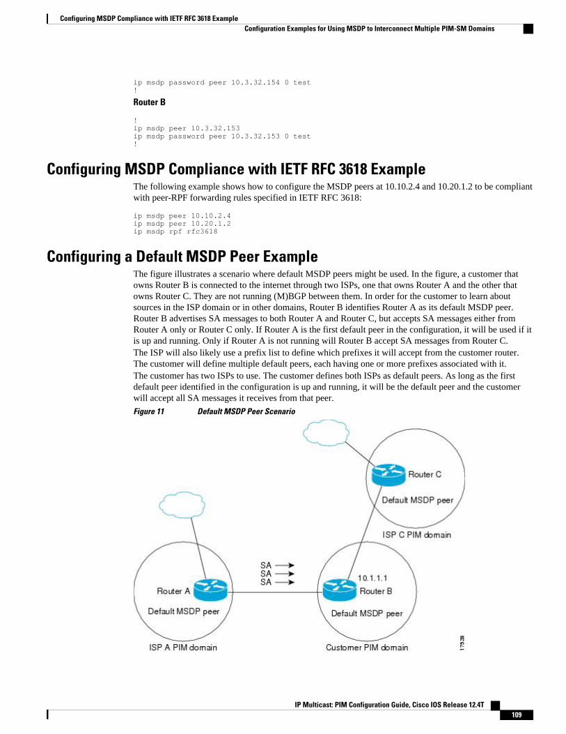
ip msdp password peer 10.3.32.154 0 test!
Router B
!ip msdp peer 10.3.32.153ip msdp password peer 10.3.32.153 0 test!
Configuring MSDP Compliance with IETF RFC 3618 ExampleThe following example shows how to configure the MSDP peers at 10.10.2.4 and 10.20.1.2 to be compliantwith peer-RPF forwarding rules specified in IETF RFC 3618:
ip msdp peer 10.10.2.4ip msdp peer 10.20.1.2ip msdp rpf rfc3618
Configuring a Default MSDP Peer ExampleThe figure illustrates a scenario where default MSDP peers might be used. In the figure, a customer thatowns Router B is connected to the internet through two ISPs, one that owns Router A and the other thatowns Router C. They are not running (M)BGP between them. In order for the customer to learn aboutsources in the ISP domain or in other domains, Router B identifies Router A as its default MSDP peer.Router B advertises SA messages to both Router A and Router C, but accepts SA messages either fromRouter A only or Router C only. If Router A is the first default peer in the configuration, it will be used if itis up and running. Only if Router A is not running will Router B accept SA messages from Router C.The ISP will also likely use a prefix list to define which prefixes it will accept from the customer router.The customer will define multiple default peers, each having one or more prefixes associated with it.The customer has two ISPs to use. The customer defines both ISPs as default peers. As long as the firstdefault peer identified in the configuration is up and running, it will be the default peer and the customerwill accept all SA messages it receives from that peer.
Figure 11 Default MSDP Peer Scenario
Configuring MSDP Compliance with IETF RFC 3618 ExampleConfiguration Examples for Using MSDP to Interconnect Multiple PIM-SM Domains
IP Multicast: PIM Configuration Guide, Cisco IOS Release 12.4T 109
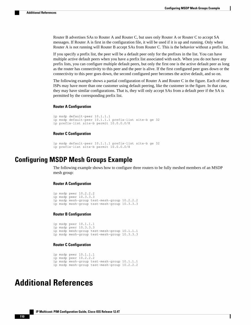
Router B advertises SAs to Router A and Router C, but uses only Router A or Router C to accept SAmessages. If Router A is first in the configuration file, it will be used if it is up and running. Only whenRouter A is not running will Router B accept SAs from Router C. This is the behavior without a prefix list.
If you specify a prefix list, the peer will be a default peer only for the prefixes in the list. You can havemultiple active default peers when you have a prefix list associated with each. When you do not have anyprefix lists, you can configure multiple default peers, but only the first one is the active default peer as longas the router has connectivity to this peer and the peer is alive. If the first configured peer goes down or theconnectivity to this peer goes down, the second configured peer becomes the active default, and so on.
The following example shows a partial configuration of Router A and Router C in the figure. Each of theseISPs may have more than one customer using default peering, like the customer in the figure. In that case,they may have similar configurations. That is, they will only accept SAs from a default peer if the SA ispermitted by the corresponding prefix list.
Router A Configuration
ip msdp default-peer 10.1.1.1ip msdp default-peer 10.1.1.1 prefix-list site-b ge 32ip prefix-list site-b permit 10.0.0.0/8
Router C Configuration
ip msdp default-peer 10.1.1.1 prefix-list site-b ge 32ip prefix-list site-b permit 10.0.0.0/8
Configuring MSDP Mesh Groups ExampleThe following example shows how to configure three routers to be fully meshed members of an MSDPmesh group:
Router A Configuration
ip msdp peer 10.2.2.2ip msdp peer 10.3.3.3ip msdp mesh-group test-mesh-group 10.2.2.2ip msdp mesh-group test-mesh-group 10.3.3.3
Router B Configuration
ip msdp peer 10.1.1.1ip msdp peer 10.3.3.3ip msdp mesh-group test-mesh-group 10.1.1.1ip msdp mesh-group test-mesh-group 10.3.3.3
Router C Configuration
ip msdp peer 10.1.1.1ip msdp peer 10.2.2.2ip msdp mesh-group test-mesh-group 10.1.1.1ip msdp mesh-group test-mesh-group 10.2.2.2
Additional References
Configuring MSDP Mesh Groups Example Additional References
IP Multicast: PIM Configuration Guide, Cisco IOS Release 12.4T110
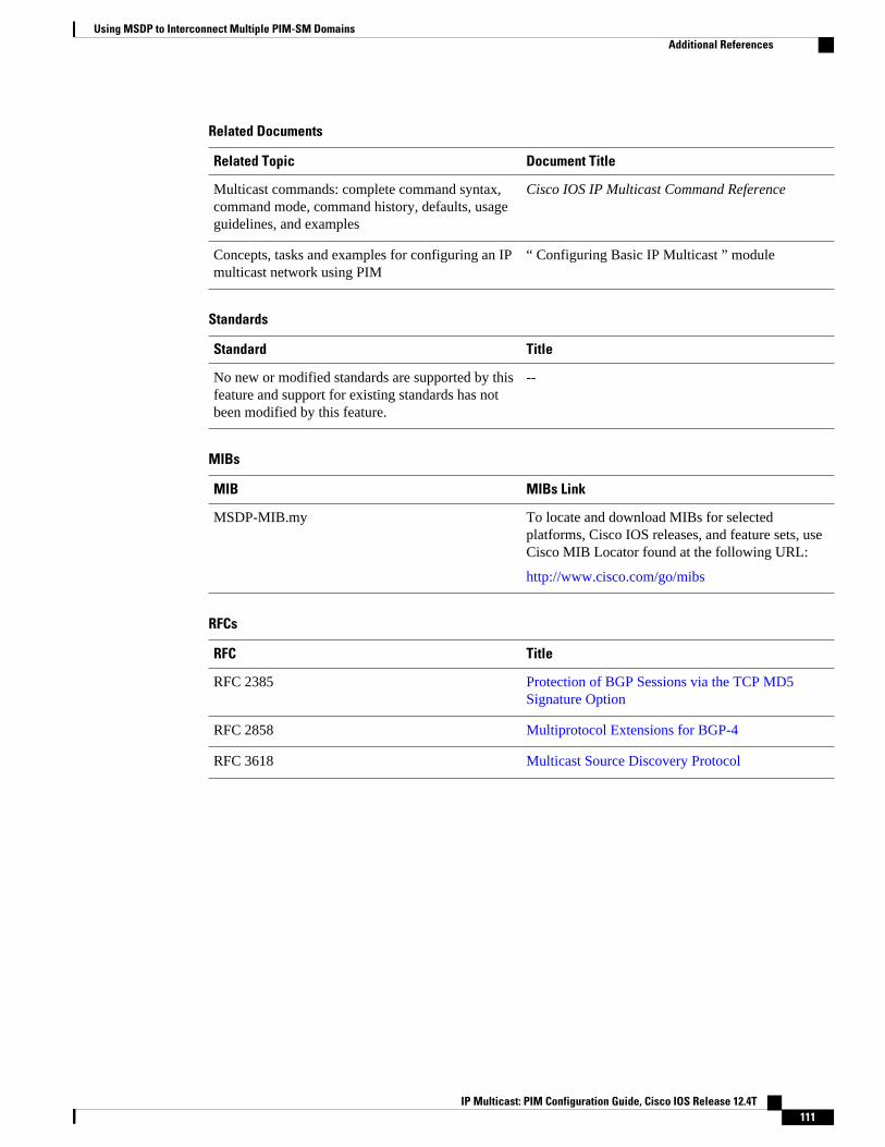
Related Documents
Related Topic Document Title
Multicast commands: complete command syntax,command mode, command history, defaults, usageguidelines, and examples
Cisco IOS IP Multicast Command Reference
Concepts, tasks and examples for configuring an IPmulticast network using PIM
“ Configuring Basic IP Multicast ” module
Standards
Standard Title
No new or modified standards are supported by thisfeature and support for existing standards has notbeen modified by this feature.
--
MIBs
MIB MIBs Link
MSDP-MIB.my To locate and download MIBs for selectedplatforms, Cisco IOS releases, and feature sets, useCisco MIB Locator found at the following URL:
http://www.cisco.com/go/mibs
RFCs
RFC Title
RFC 2385 Protection of BGP Sessions via the TCP MD5Signature Option
RFC 2858 Multiprotocol Extensions for BGP-4
RFC 3618 Multicast Source Discovery Protocol
Using MSDP to Interconnect Multiple PIM-SM DomainsAdditional References
IP Multicast: PIM Configuration Guide, Cisco IOS Release 12.4T 111
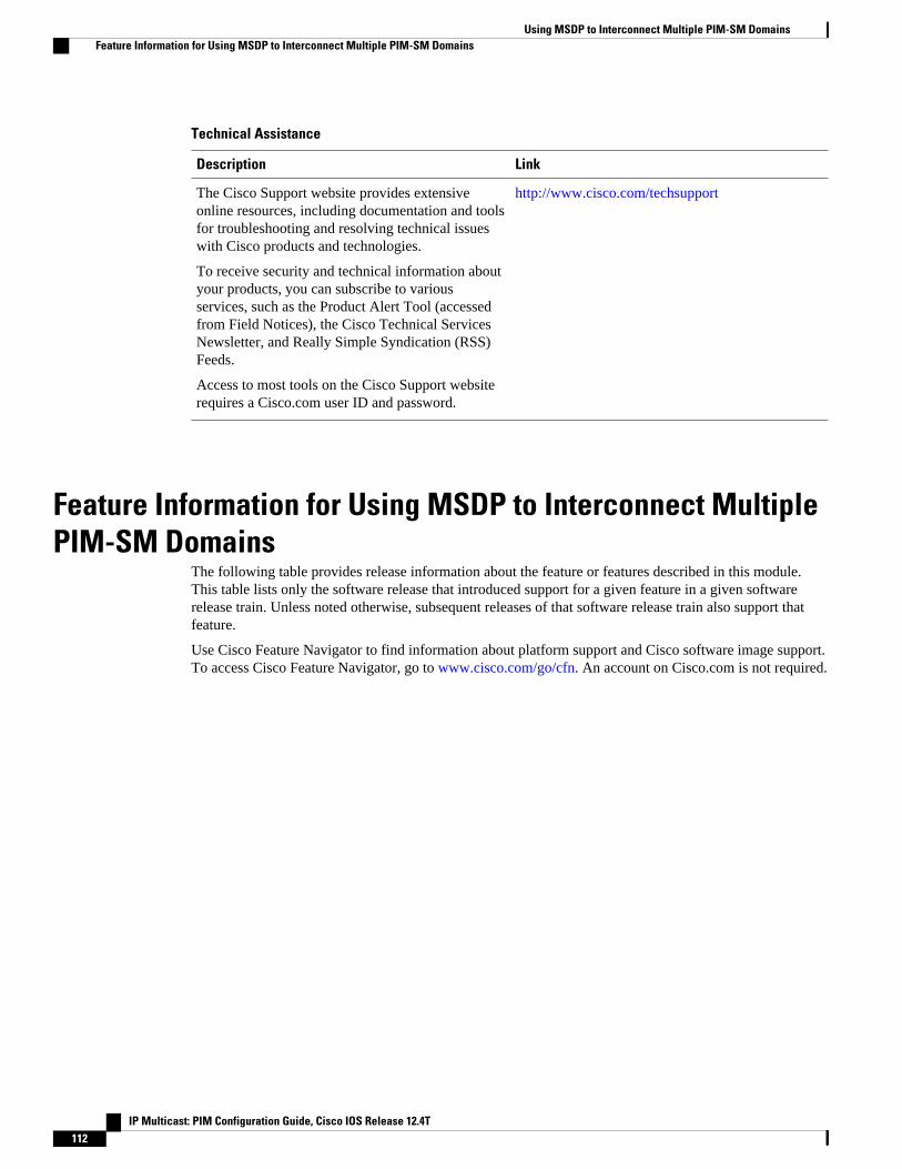
Technical Assistance
Description Link
The Cisco Support website provides extensiveonline resources, including documentation and toolsfor troubleshooting and resolving technical issueswith Cisco products and technologies.
To receive security and technical information aboutyour products, you can subscribe to variousservices, such as the Product Alert Tool (accessedfrom Field Notices), the Cisco Technical ServicesNewsletter, and Really Simple Syndication (RSS)Feeds.
Access to most tools on the Cisco Support websiterequires a Cisco.com user ID and password.
http://www.cisco.com/techsupport
Feature Information for Using MSDP to Interconnect MultiplePIM-SM Domains
The following table provides release information about the feature or features described in this module.This table lists only the software release that introduced support for a given feature in a given softwarerelease train. Unless noted otherwise, subsequent releases of that software release train also support thatfeature.
Use Cisco Feature Navigator to find information about platform support and Cisco software image support.To access Cisco Feature Navigator, go to www.cisco.com/go/cfn. An account on Cisco.com is not required.
Using MSDP to Interconnect Multiple PIM-SM Domains Feature Information for Using MSDP to Interconnect Multiple PIM-SM Domains
IP Multicast: PIM Configuration Guide, Cisco IOS Release 12.4T112
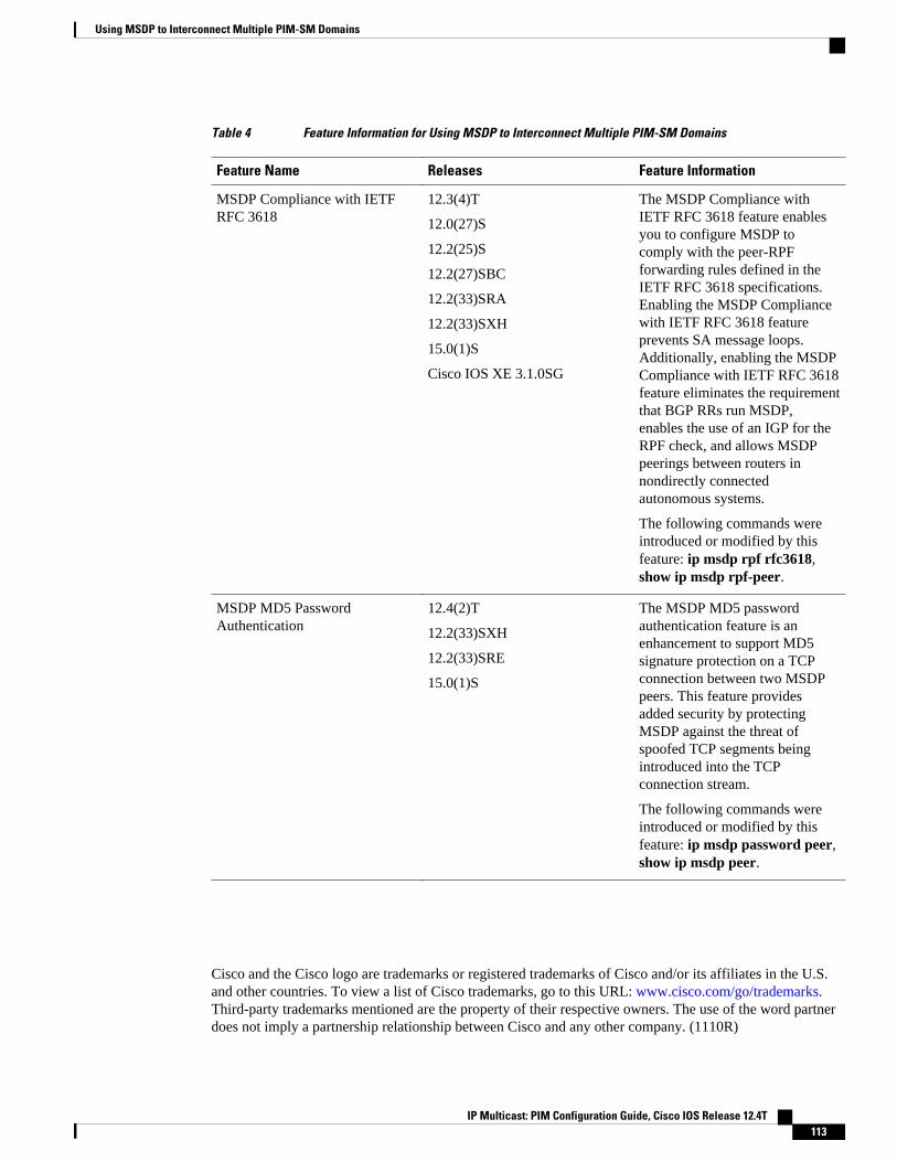
Table 4 Feature Information for Using MSDP to Interconnect Multiple PIM-SM Domains
Feature Name Releases Feature Information
MSDP Compliance with IETFRFC 3618
12.3(4)T
12.0(27)S
12.2(25)S
12.2(27)SBC
12.2(33)SRA
12.2(33)SXH
15.0(1)S
Cisco IOS XE 3.1.0SG
The MSDP Compliance withIETF RFC 3618 feature enablesyou to configure MSDP tocomply with the peer-RPFforwarding rules defined in theIETF RFC 3618 specifications.Enabling the MSDP Compliancewith IETF RFC 3618 featureprevents SA message loops.Additionally, enabling the MSDPCompliance with IETF RFC 3618feature eliminates the requirementthat BGP RRs run MSDP,enables the use of an IGP for theRPF check, and allows MSDPpeerings between routers innondirectly connectedautonomous systems.
The following commands wereintroduced or modified by thisfeature: ip msdp rpf rfc3618,show ip msdp rpf-peer.
MSDP MD5 PasswordAuthentication
12.4(2)T
12.2(33)SXH
12.2(33)SRE
15.0(1)S
The MSDP MD5 passwordauthentication feature is anenhancement to support MD5signature protection on a TCPconnection between two MSDPpeers. This feature providesadded security by protectingMSDP against the threat ofspoofed TCP segments beingintroduced into the TCPconnection stream.
The following commands wereintroduced or modified by thisfeature: ip msdp password peer,show ip msdp peer.
Cisco and the Cisco logo are trademarks or registered trademarks of Cisco and/or its affiliates in the U.S.and other countries. To view a list of Cisco trademarks, go to this URL: www.cisco.com/go/trademarks.Third-party trademarks mentioned are the property of their respective owners. The use of the word partnerdoes not imply a partnership relationship between Cisco and any other company. (1110R)
Using MSDP to Interconnect Multiple PIM-SM Domains
IP Multicast: PIM Configuration Guide, Cisco IOS Release 12.4T 113

Any Internet Protocol (IP) addresses and phone numbers used in this document are not intended to beactual addresses and phone numbers. Any examples, command display output, network topology diagrams,and other figures included in the document are shown for illustrative purposes only. Any use of actual IPaddresses or phone numbers in illustrative content is unintentional and coincidental.
Using MSDP to Interconnect Multiple PIM-SM Domains
IP Multicast: PIM Configuration Guide, Cisco IOS Release 12.4T114
Configuring Source Specific Multicast
This module describes how to configure Source Specific Multicast (SSM). The Source Specific Multicastfeature is an extension of IP multicast where datagram traffic is forwarded to receivers from only thosemulticast sources to which the receivers have explicitly joined. For multicast groups configured for SSM,only source-specific multicast distribution trees (no shared trees) are created.
• Finding Feature Information, page 115• Restrictions for Source Specific Multicast, page 115• Information About Source Specific Multicast, page 117• How to Configure Source Specific Multicast, page 122• Configuration Examples of Source Specific Multicast, page 124• Additional References, page 126
Finding Feature InformationYour software release may not support all the features documented in this module. For the latest featureinformation and caveats, see the release notes for your platform and software release. To find informationabout the features documented in this module, and to see a list of the releases in which each feature issupported, see the Feature Information Table at the end of this document.
Use Cisco Feature Navigator to find information about platform support and Cisco software image support.To access Cisco Feature Navigator, go to www.cisco.com/go/cfn. An account on Cisco.com is not required.
Restrictions for Source Specific MulticastLegacy Applications Within the SSM Range Restrictions
Existing applications in a network predating SSM will not work within the SSM range unless they aremodified to support (S, G) channel subscriptions or are enabled through URD. Therefore, enabling SSM ina network may cause problems for existing applications if they use addresses within the designated SSMrange.
IGMP v3lite and URD Require a Cisco Last Hop Router
SSM and IGMPv3 are solutions that are being standardized in the IETF. However, IGMP v3lite and URDare Cisco-developed solutions. For IGMP v3lite and URD to operate properly for a host, the last hop routertoward that host must be a Cisco router with IGMP v3lite or URD enabled.
IP Multicast: PIM Configuration Guide, Cisco IOS Release 12.4T 115
Note This limitation does not apply to an application using the HSIL if the host has kernel support for IGMPv3,because then the HSIL will use the kernel IGMPv3 instead of IGMP v3lite.
Address Management Restrictions
Address management is still necessary to some degree when SSM is used with Layer 2 switchingmechanisms. Cisco Group Management Protocol (CGMP), IGMP snooping, or Router-Port GroupManagement Protocol (RGMP) currently support only group-specific filtering, not (S, G) channel-specificfiltering. If different receivers in a switched network request different (S, G) channels sharing the samegroup, then they will not benefit from these existing mechanisms. Instead, both receivers will receive all (S,G) channel traffic (and filter out the unwanted traffic on input). Because of the ability of SSM to reuse thegroup addresses in the SSM range for many independent applications, this situation can lead to less thanexpected traffic filtering in a switched network. For this reason it is important to follow therecommendations set forth in the IETF drafts for SSM to use random IP addresses out of the SSM range foran application to minimize the chance for reuse of a single address within the SSM range between differentapplications. For example, an application service providing a set of television channels should, even withSSM, use a different group for each television (S, G) channel. This setup will guarantee that multiplereceivers to different channels within the same application service will never experience traffic aliasing innetworks that include Layer 2 switches.
IGMP Snooping and CGMP Limitations
IGMPv3 uses new membership report messages that may not be recognized correctly by older IGMPSnooping switches, in which case hosts will not properly receive traffic. This situation is not an issue ifURD or IGMP v3lite is used with hosts where the operating system is not upgraded for IGMPv3, becauseIGMP v3lite and URD rely only on IGMPv1 or IGMPv2 membership reports.
URD Intercept URL Limitations
A URD intercept URL string must be fewer than 256 bytes in length, starting from the /path argument. Inthe HTTP/TCP connection, this string must also be contained within a single TCP/IP packet. For example,for a 256-byte string, a link maximum transmission unit (MTU) of 128 bytes between the host andintercepting router would cause incorrect operation of URD.
State Maintenance Limitations
In PIM-SSM, the last hop router will continue to periodically send (S, G) join messages if appropriate (S,G) subscriptions are on the interfaces. Therefore, as long as receivers send (S, G) subscriptions, the shortestpath tree (SPT) state from the receivers to the source will be maintained, even if the source is not sendingtraffic for longer periods of time (or even never).
This case is opposite to PIM-SM, where (S, G) state is maintained only if the source is sending traffic andreceivers are joining the group. If a source stops sending traffic for more than 3 minutes in PIM-SM, the (S,G) state will be deleted and only reestablished after packets from the source arrive again through the RPT.Because no mechanism in PIM-SSM notifies a receiver that a source is active, the network must maintainthe (S, G) state in PIM-SSM as long as receivers are requesting receipt of that channel.
HSIL Limitations
As explained in the IGMP v3lite Host Signalling, page 120 concept, the HSIL tries to determine if thehost operating system supports IGMPv3. This check is made so that a single application can be used both
Configuring Source Specific Multicast Restrictions for Source Specific Multicast
IP Multicast: PIM Configuration Guide, Cisco IOS Release 12.4T116
on hosts where the operating system has been upgraded to IGMPv3 and on hosts where the operatingsystem only supports IGMPv1 or IGMPv2.
Checking for the availability of IGMPv3 in the host operating system can only be made by the HSIL ifIGMPv3 kernel support exists for at least one version of this operating system at the time when the HSILwas provided. If such an IGMPv3 kernel implementation has become available only recently, then usersmay need to also upgrade the HSIL on their hosts so that applications compiled with the HSIL will thendynamically bind to the newest version of the HSIL, which should support the check for IGMPv3 in theoperating system kernel. Upgrading the HSIL can be done independently of upgrading the applicationitself.
Information About Source Specific Multicast• SSM Overview, page 29• IGMP v3lite Host Signalling, page 120• URD Host Signalling, page 121
SSM OverviewSource Specific Multicast (SSM). SSM is an extension of IP multicast where datagram traffic is forwardedto receivers from only those multicast sources that the receivers have explicitly joined. For multicast groupsconfigured for SSM, only source-specific multicast distribution trees (not shared trees) are created.
• SSM Components, page 29• How SSM Differs from Internet Standard Multicast, page 29• SSM Operations, page 30• IGMPv3 Host Signaling, page 30• Benefits of Source Specific Multicast, page 31
SSM ComponentsSSM is a datagram delivery model that best supports one-to-many applications, also known as broadcastapplications. SSM is a core networking technology for the Cisco implementation of IP multicast solutionstargeted for audio and video broadcast application environments and is described in RFC 3569. Thefollowing two components together support the implementation of SSM:
• Protocol Independent Multicast source-specific mode (PIM-SSM)• Internet Group Management Protocol Version 3 (IGMPv3)
Protocol Independent Multicast (PIM) SSM, or PIM-SSM, is the routing protocol that supports theimplementation of SSM and is derived from PIM sparse mode (PIM-SM). IGMP is the InternetEngineering Task Force (IETF) standards track protocol used for hosts to signal multicast groupmembership to routers. IGMP Version 3 supports source filtering, which is required for SSM. IGMP ForSSM to run with IGMPv3, SSM must be supported in the router, the host where the application is running,and the application itself.
How SSM Differs from Internet Standard MulticastThe standard IP multicast infrastructure in the Internet and many enterprise intranets is based on the PIM-SM protocol and Multicast Source Discovery Protocol (MSDP). These protocols have proved to be reliable,
SSM OverviewInformation About Source Specific Multicast
IP Multicast: PIM Configuration Guide, Cisco IOS Release 12.4T 117
extensive, and efficient. However, they are bound to the complexity and functionality limitations of theInternet Standard Multicast (ISM) service model. For example, with ISM, the network must maintainknowledge about which hosts in the network are actively sending multicast traffic. With SSM, thisinformation is provided by receivers through the source addresses relayed to the last-hop routers byIGMPv3. SSM is an incremental response to the issues associated with ISM and is intended to coexist inthe network with the protocols developed for ISM. In general, SSM provides IP multicast service forapplications that utilize SSM.
ISM service is described in RFC 1112. This service consists of the delivery of IP datagrams from anysource to a group of receivers called the multicast host group. The datagram traffic for the multicast hostgroup consists of datagrams with an arbitrary IP unicast source address S and the multicast group address Gas the IP destination address. Systems will receive this traffic by becoming members of the host group.Membership in a host group simply requires signaling the host group through IGMP Version 1, 2, or 3.
In SSM, delivery of datagrams is based on (S, G) channels. Traffic for one (S, G) channel consists ofdatagrams with an IP unicast source address S and the multicast group address G as the IP destinationaddress. Systems will receive this traffic by becoming members of the (S, G) channel. In both SSM andISM, no signaling is required to become a source. However, in SSM, receivers must subscribe orunsubscribe to (S, G) channels to receive or not receive traffic from specific sources. In other words,receivers can receive traffic only from (S, G) channels to which they are subscribed, whereas in ISM,receivers need not know the IP addresses of sources from which they receive their traffic. The proposedstandard approach for channel subscription signaling utilizes IGMP INCLUDE mode membership reports,which are supported only in IGMP Version 3.
SSM can coexist with the ISM service by applying the SSM delivery model to a configured subset of the IPmulticast group address range. The Internet Assigned Numbers Authority (IANA) has reserved the addressrange from 232.0.0.0 through 232.255.255.255 for SSM applications and protocols. The software allowsSSM configuration for an arbitrary subset of the IP multicast address range from 224.0.0.0 through239.255.255.255. When an SSM range is defined, an existing IP multicast receiver application will notreceive any traffic when it tries to use addresses in the SSM range unless the application is modified to useexplicit (S, G) channel subscription or is SSM-enabled through a URL Rendezvous Directory (URD).
SSM OperationsAn established network in which IP multicast service is based on PIM-SM can support SSM services. SSMcan also be deployed alone in a network without the full range of protocols that are required forinterdomain PIM-SM. That is, SSM does not require an RP, so there is no need for an RP mechanism suchas Auto-RP, MSDP, or bootstrap router (BSR).
If SSM is deployed in a network that is already configured for PIM-SM, then only the last-hop routers mustbe upgraded to a software image that supports SSM. Routers that are not directly connected to receivers donot have to upgrade to a software image that supports SSM. In general, these non-last-hop routers mustonly run PIM-SM in the SSM range. They may need additional access control configuration to suppressMSDP signaling, registering, or PIM-SM shared-tree operations from occurring within the SSM range.
The SSM mode of operation is enabled by configuring the SSM range using the ip pim ssm globalconfiguration command. This configuration has the following effects:
• For groups within the SSM range, (S, G) channel subscriptions are accepted through IGMPv3INCLUDE mode membership reports.
• PIM operations within the SSM range of addresses change to PIM-SSM, a mode derived from PIM-SM. In this mode, only PIM (S, G) Join and Prune messages are generated by the router. Incomingmessages related to rendezvous point tree (RPT) operations are ignored or rejected, and incoming PIMregister messages are immediately answered with Register-Stop messages. PIM-SSM is backward-
Configuring Source Specific Multicast SSM Operations
IP Multicast: PIM Configuration Guide, Cisco IOS Release 12.4T118
compatible with PIM-SM unless a router is a last-hop router. Therefore, routers that are not last-hoprouters can run PIM-SM for SSM groups (for example, if they do not yet support SSM).
• For groups within the SSM range, no MSDP Source-Active (SA) messages within the SSM range willbe accepted, generated, or forwarded.
IGMPv3 Host SignalingIGMPv3 is the third version of the IETF standards track protocol in which hosts signal membership to last-hop routers of multicast groups. IGMPv3 introduces the ability for hosts to signal group membership thatallows filtering capabilities with respect to sources. A host can signal either that it wants to receive trafficfrom all sources sending to a group except for some specific sources (a mode called EXCLUDE) or that itwants to receive traffic only from some specific sources sending to the group (a mode called INCLUDE).
IGMPv3 can operate with both ISM and SSM. In ISM, both EXCLUDE and INCLUDE mode reports areaccepted by the last-hop router. In SSM, only INCLUDE mode reports are accepted by the last-hop router.
Benefits of Source Specific Multicast
IP Multicast Address Management Not Required
In the ISM service, applications must acquire a unique IP multicast group address because trafficdistribution is based only on the IP multicast group address used. If two applications with different sourcesand receivers use the same IP multicast group address, then receivers of both applications will receivetraffic from the senders of both applications. Even though the receivers, if programmed appropriately, canfilter out the unwanted traffic, this situation would cause generally unacceptable levels of unwanted traffic.
Allocating a unique IP multicast group address for an application is still a problem. Most short-livedapplications use mechanisms like Session Description Protocol (SDP) and Session Announcement Protocol(SAP) to get a random address, a solution that does not work well with a rising number of applications inthe Internet. The best current solution for long-lived applications is described in RFC 2770, but thissolution suffers from the restriction that each autonomous system is limited to only 255 usable IP multicastaddresses.
In SSM, traffic from each source is forwarded between routers in the network independent of traffic fromother sources. Thus different sources can reuse multicast group addresses in the SSM range.
Denial of Service Attacks from Unwanted Sources Inhibited
In SSM, multicast traffic from each individual source will be transported across the network only if it wasrequested (through IGMPv3, IGMP v3lite, or URD memberships) from a receiver. In contrast, ISMforwards traffic from any active source sending to a multicast group to all receivers requesting thatmulticast group. In Internet broadcast applications, this ISM behavior is highly undesirable because itallows unwanted sources to easily disturb the actual Internet broadcast source by simply sending traffic tothe same multicast group. This situation depletes bandwidth at the receiver side with unwanted traffic andthus disrupts the undisturbed reception of the Internet broadcast. In SSM, this type of denial of service(DoS) attack cannot be made by simply sending traffic to a multicast group.
Easy to Install and Manage
SSM is easy to install and provision in a network because it does not require the network to maintain whichactive sources are sending to multicast groups. This requirement exists in ISM (with IGMPv1, IGMPv2, orIGMPv3).
The current standard solutions for ISM service are PIM-SM and MSDP. Rendezvous point (RP)management in PIM-SM (including the necessity for Auto-RP or BSR) and MSDP is required only for the
Configuring Source Specific MulticastIGMPv3 Host Signaling
IP Multicast: PIM Configuration Guide, Cisco IOS Release 12.4T 119
network to learn about active sources. This management is not necessary in SSM, which makes SSM easierthan ISM to install and manage, and therefore easier than ISM to operationally scale in deployment.Another factor that contributes to the ease of installation of SSM is the fact that it can leverage preexistingPIM-SM networks and requires only the upgrade of last hop routers to support IGMPv3, IGMP v3lite, orURD.
Ideal for Internet Broadcast Applications
The three benefits previously described make SSM ideal for Internet broadcast-style applications for thefollowing reasons:
• The ability to provide Internet broadcast services through SSM without the need for unique IPmulticast addresses allows content providers to easily offer their service (IP multicast addressallocation has been a serious problem for content providers in the past).
• The prevention against DoS attacks is an important factor for Internet broadcast services because, withtheir exposure to a large number of receivers, they are the most common targets for such attacks.
• The ease of installation and operation of SSM makes it ideal for network operators, especially in thosecases where content needs to be forwarded between multiple independent PIM domains (because thereis no need to manage MSDP for SSM between PIM domains).
IGMP v3lite Host SignallingIGMP v3lite is a Cisco-developed transitional solution for application developers to immediately startprogramming SSM applications. It allows you to write and run SSM applications on hosts that do not yetsupport IGMPv3 in their operating system kernel.
Applications must be compiled with the Host Side IGMP Library (HSIL) for IGMP v3lite. This softwareprovides applications with a subset of the IGMPv3 applications programming interface (API) that isrequired to write SSM applications. HSIL was developed for Cisco by Talarian and is available from thefollowing web page:
http://www.talarianmulticast.com/cgi-bin/igmpdownld
One part of the HSIL is a client library linked to the SSM application. It provides the SSM subset of theIGMPv3 API to the SSM application. If possible, the library checks whether the operating system kernelsupports IGMPv3. If it does, then the API calls simply are passed through to the kernel. If the kernel doesnot support IGMPv3, then the library uses the IGMP v3lite mechanism.
When using the IGMP v3lite mechanism, the library tells the operating system kernel to join to the wholemulticast group, because joining to the whole group is the only method for the application to receive trafficfor that multicast group (if the operating system kernel only supports IGMPv1 or IGMPv2). In addition, thelibrary signals the (S, G) channel subscriptions to an IGMP v3lite server process, which is also part of theHSIL. A server process is needed because multiple SSM applications may be on the same host. This serverprocess will then send IGMP v3lite-specific (S, G) channel subscriptions to the last hop Cisco IOS router,which needs to be enabled for IGMP v3lite. This router will then “see” both the IGMPv1 or IGMPv2 groupmembership report from the operating system kernel and the (S, G) channel subscription from the HSILdaemon. If the router sees both of these messages, it will interpret them as an SSM (S, G) channelsubscription and join to the channel through PIM-SSM. We recommend referring to the documentationaccompanying the HSIL software for further information on how to utilize IGMP v3lite with yourapplication.
IGMP v3lite is supported by Cisco only through the API provided by the HSIL, not as a function of therouter independent of the HSIL. By default, IGMP v3lite is disabled. When IGMP v3lite is configuredthrough the ip igmp v3lite interface configuration command on an interface, it will be active only for IPmulticast addresses in the SSM range.
IGMP v3lite Host Signalling Benefits of Source Specific Multicast
IP Multicast: PIM Configuration Guide, Cisco IOS Release 12.4T120
URD Host SignallingURD is a Cisco-developed transitional solution that allows existing IP multicast receiver applications to beused with SSM without the need to modify the application and change or add any software on the receiverhost running the application. URD is a content provider solution in which the receiver applications can bestarted or controlled through a web browser.
URD operates by passing a special URL from the web browser to the last hop router. This URL is called aURD intercept URL. A URD intercept URL is encoded with the (S, G) channel subscription and has aformat that allows the last hop router to easily intercept it.
As soon as the last hop router intercepts both an (S, G) channel subscription encoded in a URD interceptURL and sees an IGMP group membership report for the same multicast group from the receiverapplication, the last hop router will use PIM-SSM to join toward the (S, G) channel as long as theapplication maintains the membership for the multicast group G. The URD intercept URL is thus onlyneeded initially to provide the last hop router with the address of the sources to join to.
A URD intercept URL has the following syntax:
http://webserver:465/path?group=group&source=source1&...source=sourceN&
The webserver string is the name or IP address to which the URL is targeted. This target need not be the IPaddress of an existing web server, except for situations where the web server wants to recognize that thelast hop router failed to support the URD mechanism. The number 465 indicates the URD port. Port 465 isreserved for Cisco by the IANA for the URD mechanism so that no other applications can use this port.
When the browser of a host encounters a URD intercept URL, it will try to open a TCP connection to theweb server on port 465. If the last hop router is enabled for URD on the interface where the router receivesthe TCP packets from the host, it will intercept all packets for TCP connections destined to port 465independent of the actual destination address of the TCP connection (independent of the address of the webserver). Once intercepted, the last hop router will “speak” a very simple subset of HTTP on this TCPconnection, emulating a web server. The only HTTP request that the last hop router will understand andreply to is the following GET request:
GET argument HTTP/1.0argument = /path?group=group&source=source1&...source=sourceN&
When it receives a GET command, the router tries to parse the argument according to this syntax to deriveone or more (S, G) channel memberships. The path string of the argument is anything up to, but notincluding, the first question mark, and is ignored. The group and source1 through sourceN strings are theIP addresses or fully qualified domain names of the channels for which this argument is a subscription
URD Host SignallingBenefits of Source Specific Multicast
IP Multicast: PIM Configuration Guide, Cisco IOS Release 12.4T 121
request. If the argument matches the syntax shown, the router interprets the argument to be subscriptionsfor the channels (source1 , group ) through (sourceN , group ).
The router will accept the channel subscriptions if the following conditions are met:
• The IP address of the multicast group is within the SSM range.• The IP address of the host that originated the TCP connection is directly connected to the router.
If the channel subscription is accepted, the router will respond to the TCP connection with the followingHTML page format:
HTTP/1.1 200 OKServer:cisco IOSContent-Type:text/html<html><body>Retrieved URL string successfully</body></html>
If an error condition occurs, the <body> part of the returned HTML page will carry an appropriate errormessage. The HTML page is a by-product of the URD mechanism. This returned text may, depending onhow the web pages carrying a URD intercept URL are designed, be displayed to the user or be sized so thatthe actual returned HTML page is invisible.
The primary effect of the URD mechanism is that the router will remember received channel subscriptionsand will match them against IGMP group membership reports received by the host. The router will“remember” a URD (S, G) channel subscription for up to 3 minutes without a matching IGMP groupmembership report. As soon as the router sees that it has received both an IGMP group membership reportfor a multicast group G and a URD (S, G) channel subscription for the same group G, it will join the (S, G)channel through PIM-SSM. The router will then continue to join to the (S, G) channel based only on thepresence of a continuing IGMP membership from the host. Thus, one initial URD channel subscription isall that is needed to be added through a web page to enable SSM with URD.
If the last hop router from the receiver host is not enabled for URD, then it will not intercept the HTTPconnection toward the web server on port 465. This situation will result in a TCP connection to port 465 onthe web server. If no further provisions on the web server are taken, then the user may see a notice (forexample, “Connection refused”) in the area of the web page reserved for displaying the URD interceptURL (if the web page was designed to show this output). It is also possible to let the web server “listen” torequests on port 465 and install a Common Gateway Interface (CGI) script that would allow the web serverto know if a channel subscription failed (for example, to subsequently return more complex errordescriptions to the user).
Because the router returns a Content-Type of text and HTML, the best way to include the URD interceptURL into a web page is to use a frame. By defining the size of the frame, you can also hide the URDintercept URL on the displayed page.
By default, URD is disabled on all interfaces. When URD is configured through the ip urd interfaceconfiguration command on an interface, it will be active only for IP multicast addresses in the SSM range.
How to Configure Source Specific Multicast• Configuring SSM, page 123
• Monitoring SSM, page 124
Configuring Source Specific Multicast How to Configure Source Specific Multicast
IP Multicast: PIM Configuration Guide, Cisco IOS Release 12.4T122
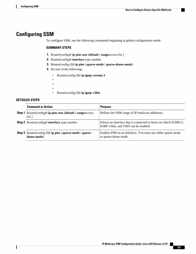
Configuring SSMTo configure SSM, use the following commands beginning in global configuration mode:
SUMMARY STEPS
1. Router(config)# ip pim ssm [default | rangeaccess-list ]
2. Router(config)# interface type number
3. Router(config-if)# ip pim {sparse-mode | sparse-dense-mode}
4. Do one of the following:
• Router(config-if)# ip igmp version 3•••• Router(config-if)# ip igmp v3lite
DETAILED STEPS
Command or Action Purpose
Step 1 Router(config)# ip pim ssm [default | rangeaccess-list ]
Defines the SSM range of IP multicast addresses.
Step 2 Router(config)# interface type number Selects an interface that is connected to hosts on which IGMPv3,IGMP v3lite, and URD can be enabled.
Step 3 Router(config-if)# ip pim {sparse-mode | sparse-dense-mode}
Enables PIM on an interface. You must use either sparse modeor sparse-dense mode.
Configuring SSMHow to Configure Source Specific Multicast
IP Multicast: PIM Configuration Guide, Cisco IOS Release 12.4T 123
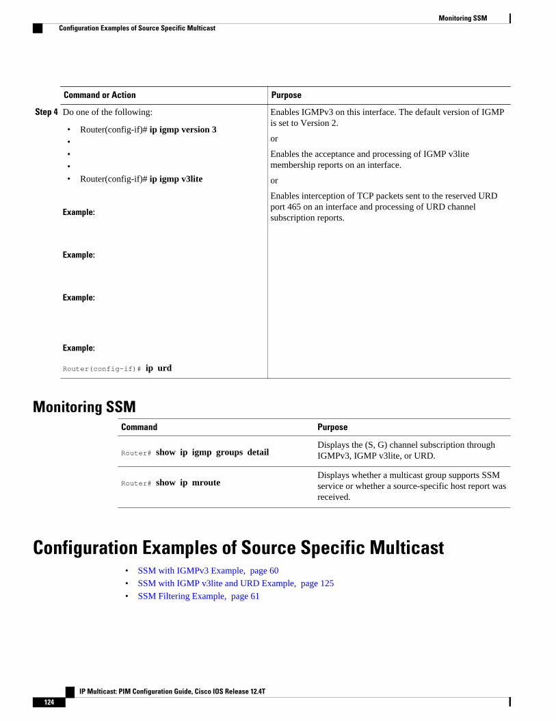
Command or Action Purpose
Step 4 Do one of the following:
• Router(config-if)# ip igmp version 3•••• Router(config-if)# ip igmp v3lite
Example:
Example:
Example:
Example:
Router(config-if)# ip urd
Enables IGMPv3 on this interface. The default version of IGMPis set to Version 2.
or
Enables the acceptance and processing of IGMP v3litemembership reports on an interface.
or
Enables interception of TCP packets sent to the reserved URDport 465 on an interface and processing of URD channelsubscription reports.
Monitoring SSMCommand Purpose
Router# show ip igmp groups detailDisplays the (S, G) channel subscription throughIGMPv3, IGMP v3lite, or URD.
Router# show ip mrouteDisplays whether a multicast group supports SSMservice or whether a source-specific host report wasreceived.
Configuration Examples of Source Specific Multicast• SSM with IGMPv3 Example, page 60
• SSM with IGMP v3lite and URD Example, page 125
• SSM Filtering Example, page 61
Monitoring SSM Configuration Examples of Source Specific Multicast
IP Multicast: PIM Configuration Guide, Cisco IOS Release 12.4T124
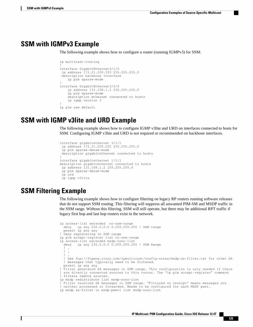
SSM with IGMPv3 ExampleThe following example shows how to configure a router (running IGMPv3) for SSM:
ip multicast-routing !interface GigabitEthernet3/1/0 ip address 172.21.200.203 255.255.255.0 description backbone interface ip pim sparse-mode ! interface GigabitEthernet3/2/0 ip address 131.108.1.2 255.255.255.0 ip pim sparse-mode description ethernet connected to hosts ip igmp version 3 ! ip pim ssm default
SSM with IGMP v3lite and URD ExampleThe following example shows how to configure IGMP v3lite and URD on interfaces connected to hosts forSSM. Configuring IGMP v3lite and URD is not required or recommended on backbone interfaces.
interface gigabitethernet 3/1/1 ip address 172.21.200.203 255.255.255.0 ip pim sparse-dense-mode description gigabitethernet connected to hosts!interface gigabitethernet 1/1/1description gigabitethernet connected to hosts ip address 131.108.1.2 255.255.255.0 ip pim sparse-dense-mode ip urd ip igmp v3lite
SSM Filtering ExampleThe following example shows how to configure filtering on legacy RP routers running software releasesthat do not support SSM routing. This filtering will suppress all unwanted PIM-SM and MSDP traffic inthe SSM range. Without this filtering, SSM will still operate, but there may be additional RPT traffic iflegacy first hop and last hop routers exist in the network.
ip access-list extended no-ssm-range deny ip any 232.0.0.0 0.255.255.255 ! SSM range permit ip any any! Deny registering in SSM rangeip pim accept-register list no-ssm-rangeip access-list extended msdp-nono-list deny ip any 232.0.0.0 0.255.255.255 ! SSM Range ! . ! . ! . ! See ftp://ftpeng.cisco.com/ipmulticast/config-notes/msdp-sa-filter.txt for other SA ! messages that typically need to be filtered. permit ip any any! Filter generated SA messages in SSM range. This configuration is only needed if there! are directly connected sources to this router. The “ip pim accept-register” command! filters remote sources.ip msdp redistribute list msdp-nono-list! Filter received SA messages in SSM range. “Filtered on receipt” means messages are! neither processed or forwarded. Needs to be configured for each MSDP peer.ip msdp sa-filter in msdp-peer1 list msdp-nono-list
SSM with IGMPv3 ExampleConfiguration Examples of Source Specific Multicast
IP Multicast: PIM Configuration Guide, Cisco IOS Release 12.4T 125
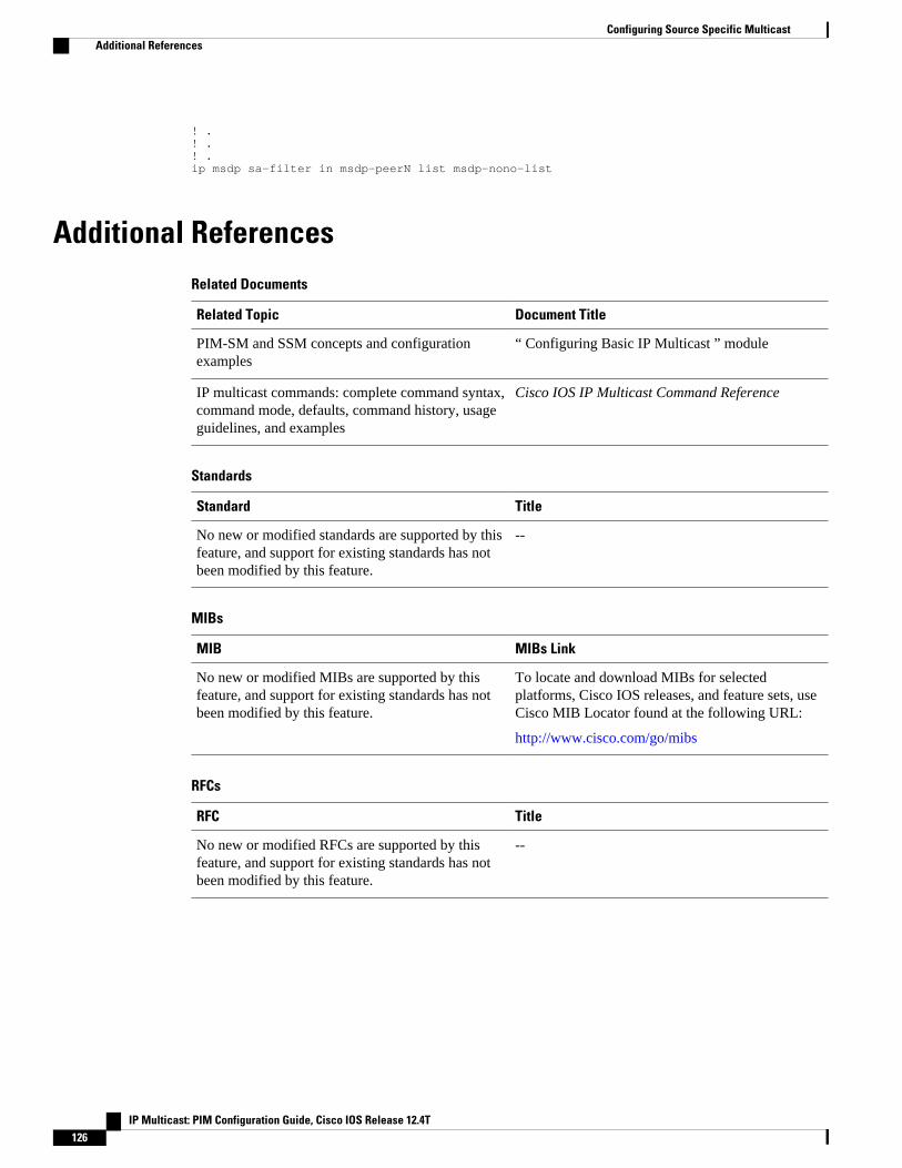
! .! .! .ip msdp sa-filter in msdp-peerN list msdp-nono-list
Additional ReferencesRelated Documents
Related Topic Document Title
PIM-SM and SSM concepts and configurationexamples
“ Configuring Basic IP Multicast ” module
IP multicast commands: complete command syntax,command mode, defaults, command history, usageguidelines, and examples
Cisco IOS IP Multicast Command Reference
Standards
Standard Title
No new or modified standards are supported by thisfeature, and support for existing standards has notbeen modified by this feature.
--
MIBs
MIB MIBs Link
No new or modified MIBs are supported by thisfeature, and support for existing standards has notbeen modified by this feature.
To locate and download MIBs for selectedplatforms, Cisco IOS releases, and feature sets, useCisco MIB Locator found at the following URL:
http://www.cisco.com/go/mibs
RFCs
RFC Title
No new or modified RFCs are supported by thisfeature, and support for existing standards has notbeen modified by this feature.
--
Configuring Source Specific Multicast Additional References
IP Multicast: PIM Configuration Guide, Cisco IOS Release 12.4T126
Technical Assistance
Description Link
The Cisco Support website provides extensiveonline resources, including documentation and toolsfor troubleshooting and resolving technical issueswith Cisco products and technologies.
To receive security and technical information aboutyour products, you can subscribe to variousservices, such as the Product Alert Tool (accessedfrom Field Notices), the Cisco Technical ServicesNewsletter, and Really Simple Syndication (RSS)Feeds.
Access to most tools on the Cisco Support websiterequires a Cisco.com user ID and password.
http://www.cisco.com/techsupport
Cisco and the Cisco logo are trademarks or registered trademarks of Cisco and/or its affiliates in the U.S.and other countries. To view a list of Cisco trademarks, go to this URL: www.cisco.com/go/trademarks.Third-party trademarks mentioned are the property of their respective owners. The use of the word partnerdoes not imply a partnership relationship between Cisco and any other company. (1110R)
Any Internet Protocol (IP) addresses and phone numbers used in this document are not intended to beactual addresses and phone numbers. Any examples, command display output, network topology diagrams,and other figures included in the document are shown for illustrative purposes only. Any use of actual IPaddresses or phone numbers in illustrative content is unintentional and coincidental.
Configuring Source Specific Multicast
IP Multicast: PIM Configuration Guide, Cisco IOS Release 12.4T 127

SSM Filtering Example
IP Multicast: PIM Configuration Guide, Cisco IOS Release 12.4T128
Implementing Multicast Stub Routing
This module describes the concepts and configuration tasks used to implement multicast stub routing.Multicast stub routing can be used for the following purposes:
• To prevent multicast transit when it is enforced by unicast stub routing.• To eliminate periodic flooding and pruning of dense mode traffic on low bandwidth links.• To reduce overall processing of Protocol Indendent Multicast (PIM) control traffic; and protect
against multicast spoofing of PIM Designated Router (DR) messages and PIM assert messages.
• Finding Feature Information, page 129• Prerequisites for Multicast Stub Routing, page 129• Restrictions for Multicast Stub Routing, page 130• Information About Multicast Stub Routing, page 130• How to Implement Multicast Stub Routing, page 131• Configuration Examples for Implementing Multicast Stub Routing, page 137• Additional References, page 141• Feature Information for Implementing Multicast Stub Routing, page 142
Finding Feature InformationYour software release may not support all the features documented in this module. For the latest featureinformation and caveats, see the release notes for your platform and software release. To find informationabout the features documented in this module, and to see a list of the releases in which each feature issupported, see the Feature Information Table at the end of this document.
Use Cisco Feature Navigator to find information about platform support and Cisco software image support.To access Cisco Feature Navigator, go to www.cisco.com/go/cfn. An account on Cisco.com is not required.
Prerequisites for Multicast Stub Routing• Before performing the tasks in this module, you should be familiar with the concepts explained in the
“ IP Multicast Technology Overview ” module.• The tasks in this module assume that IP multicast has been enabled and that the PIM interfaces have
been configured using the tasks described in the “ Configuring Basic IP Multicast ” module.
IP Multicast: PIM Configuration Guide, Cisco IOS Release 12.4T 129
Restrictions for Multicast Stub Routing• Multicast stub routing does not prevent the configuration of other Interior Gateway Protocols (IGPs)
that do not support stub routing, such as Routing Information Protocol (RIP), Open Shortest Path First(OSPF), and Intermediate System-to-Intermediate System (IS-IS) to bypass this restriction. Multicaststub routing also does not prevent the configuration of static routing to bypass this restriction.Multicast stub routing is enforced by unicast stub routing. The proper unicast Enhanced InteriorGateway Routing Protocol (EIGRP) stub routing configuration will assist in multicast stub routing.
Note For more information about unicast EIGRP stub routing, see the “Configuring EIGRP” module.
• Multicast stub routing can be only implemented in nonredundant stub network topologies.
Information About Multicast Stub Routing• Multicast Stub Networks, page 130
• Multicast Stub Routing, page 130
• Benefits of Multicast Stub Routing, page 131
Multicast Stub NetworksMulticast stub networks are those segments that receivers are directly connected to for any multicast group,even though there are receivers interested in multicast traffic beyond those segments. The Cisco IOSsoftware allows only the configuration of nonredundant multicast stub networks with the use of multicaststub routing.
Multicast Stub RoutingMulticast stub routing can be used on two types of links for multicast stub networks:
• Upstream link between the stub and distribution router--The stub router’s interface facing thedistribution router has full PIM functionality; a distribution router’s interface facing the stub routerdoes not and relies on a PIM neighbor filter or operates in PIM passive mode.
• Downstream link between the stub router and interested receiver--Downstream links are connected toLayer 2 access domains, such as VLANs, or Layer 3 routed interfaces. The downstream link operatesin PIM passive mode and assumes that it is the only interface on that access domain, making it theDesignated Router (DR). In Cisco IOS releases that do not support PIM passive mode, the downstreamlink relies on a PIM neighbor filter to prevent the stub router from discovering other PIM neighbors onthat interface. In addition, an Interior Group Management Protocol (IGMP) helper is used to proxyIGMP reports to the distribution router’s link facing the stub router.
• Multicast Stub Routing Between Stub and Distribution Routers, page 131
• Multicast Stub Routing Between the Stub Router and Interested Receivers, page 131
Multicast Stub Networks Restrictions for Multicast Stub Routing
IP Multicast: PIM Configuration Guide, Cisco IOS Release 12.4T130
Multicast Stub Routing Between Stub and Distribution RoutersImplementing multicast stub routing between the stub and distribution router is useful in PIM dense mode(PIM-DM) where periodic flooding and subsequent pruning of multicast traffic occurs for unwantedmulticast groups. Multicast stub routing in this scenario prevents periodic flooding and pruning and alsoallows multicast traffic to be forwarded for groups in which receivers are available on the stub network.
Implementing multicast stub routing between the stub and distribution router in PIM sparse mode (PIM-SM) and bidirectional PIM (bidir-PIM) environments eliminates the need to maintain the group-to-Rendezvous Point (RP) mapping cache on the stub router, and saves periodic update bandwidth--if Auto-RP or PIM bootstrap router (BSR) is used for distributing the RP information.
Multicast stub routing is intended to forward multicast traffic from the distribution to the stub router.Although it is possible to have sources directly connected to the stub network, it would only work in aPIM-DM environment. It is not possible in PIM-SM, Source Specific Multicast (SSM), and bidirectionalPIM (bidir-PIM) environments because the first hop router will be filtered by the PIM neighbor filterapplied on the distribution router, resulting in reverse path forwarding (RPF) failures. Furthermore,receivers must be directly connected to the stub router and cannot be further downstream.
Multicast Stub Routing Between the Stub Router and Interested ReceiversImplementing multicast stub routing between the stub router and interested receivers is used to reduce theoverall processing of PIM control traffic, especially as the number of stub links increases on the stub router,and to protect against DoS attacks targeted at the PIM DR.
Benefits of Multicast Stub RoutingMulticast stub routing allows such stub networks to be configured easily for multicast connectivity andprovides the following benefits:
• Prevents stub networks from being used for multicast transit when they are enforced by unicast stubrouting (EIGRP).
• Eliminates periodic flooding and pruning of dense mode traffic on low bandwidth links.• Reduces overall processing of PIM control traffic.• Protects against multicast spoofing of PIM DR messages and PIM assert messages.
Note Multicast stub routing can only be implemented in nonredundant stub network topologies.
How to Implement Multicast Stub Routing• Implementing Multicast Stub Routing, page 131
Implementing Multicast Stub RoutingPerform the following tasks to implement multicast stub routing:
• Prerequisites, page 132• Restrictions, page 132
Benefits of Multicast Stub RoutingMulticast Stub Routing Between Stub and Distribution Routers
IP Multicast: PIM Configuration Guide, Cisco IOS Release 12.4T 131
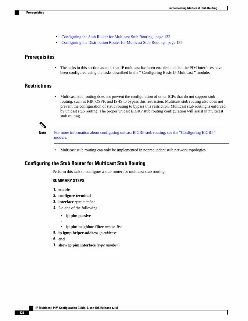
• Configuring the Stub Router for Multicast Stub Routing, page 132
• Configuring the Distribution Router for Multicast Stub Routing, page 135
Prerequisites
• The tasks in this section assume that IP multicast has been enabled and that the PIM interfaces havebeen configured using the tasks described in the “ Configuring Basic IP Multicast ” module.
Restrictions
• Multicast stub routing does not prevent the configuration of other IGPs that do not support stubrouting, such as RIP, OSPF, and IS-IS to bypass this restriction. Multicast stub routing also does notprevent the configuration of static routing to bypass this restriction. Multicast stub routing is enforcedby unicast stub routing. The proper unicast EIGRP stub routing configuration will assist in multicaststub routing.
Note For more information about configuring unicast EIGRP stub routing, see the “Configuring EIGRP”module.
• Multicast stub routing can only be implemented in nonredundant stub network topologies.
Configuring the Stub Router for Multicast Stub RoutingPerform this task to configure a stub router for multicast stub routing.
SUMMARY STEPS
1. enable
2. configure terminal
3. interface type number
4. Do one of the following:
• ip pim passive•• ip pim neighbor-filter access-list
5. ip igmp helper-address ip-address
6. end
7. show ip pim interface [type number]
Implementing Multicast Stub Routing Prerequisites
IP Multicast: PIM Configuration Guide, Cisco IOS Release 12.4T132

DETAILED STEPS
Command or Action Purpose
Step 1 enable
Example:
Router> enable
Enables privileged EXEC mode.
• Enter your password if prompted.
Step 2 configure terminal
Example:
Router# configure terminal
Enters global configuration mode.
Step 3 interface type number
Example:
Router(config)# interface GigabitEthernet0/0
Enters interface configuration mode.
Implementing Multicast Stub RoutingConfiguring the Stub Router for Multicast Stub Routing
IP Multicast: PIM Configuration Guide, Cisco IOS Release 12.4T 133
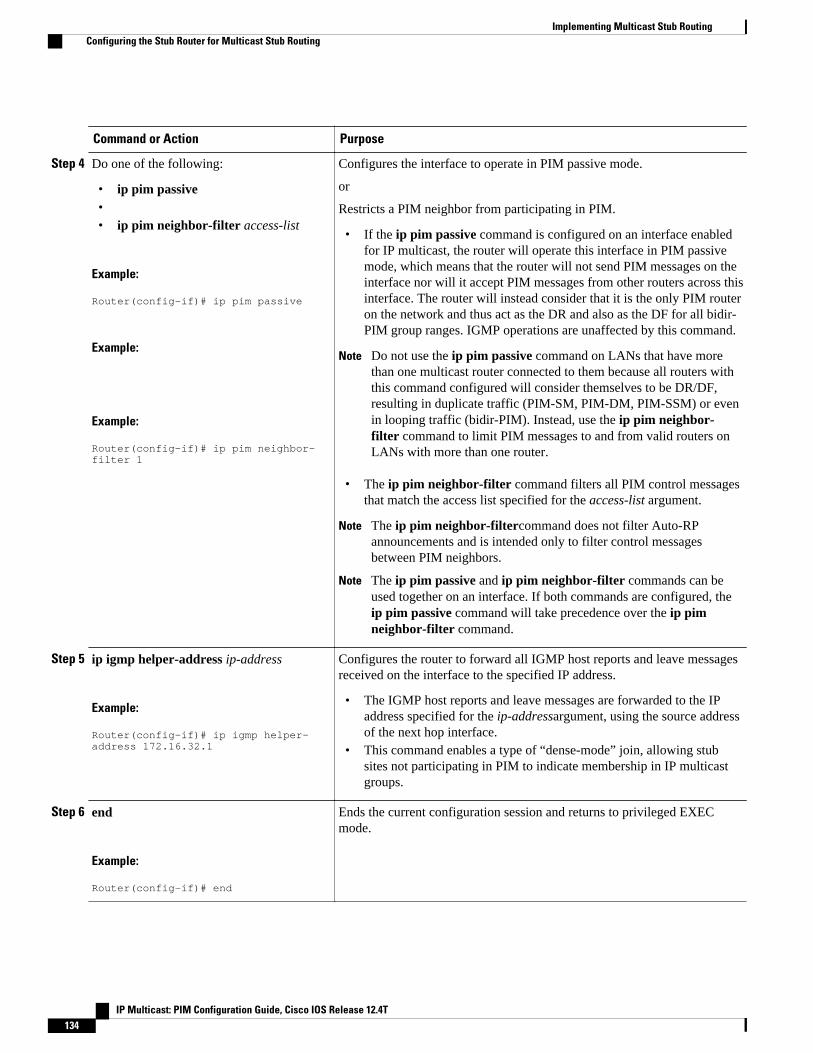
Command or Action Purpose
Step 4 Do one of the following:
• ip pim passive•• ip pim neighbor-filter access-list
Example:
Router(config-if)# ip pim passive
Example:
Example:
Router(config-if)# ip pim neighbor-filter 1
Configures the interface to operate in PIM passive mode.
or
Restricts a PIM neighbor from participating in PIM.
• If the ip pim passive command is configured on an interface enabledfor IP multicast, the router will operate this interface in PIM passivemode, which means that the router will not send PIM messages on theinterface nor will it accept PIM messages from other routers across thisinterface. The router will instead consider that it is the only PIM routeron the network and thus act as the DR and also as the DF for all bidir-PIM group ranges. IGMP operations are unaffected by this command.
Note Do not use the ip pim passive command on LANs that have morethan one multicast router connected to them because all routers withthis command configured will consider themselves to be DR/DF,resulting in duplicate traffic (PIM-SM, PIM-DM, PIM-SSM) or evenin looping traffic (bidir-PIM). Instead, use the ip pim neighbor-filter command to limit PIM messages to and from valid routers onLANs with more than one router.
• The ip pim neighbor-filter command filters all PIM control messagesthat match the access list specified for the access-list argument.
Note The ip pim neighbor-filtercommand does not filter Auto-RPannouncements and is intended only to filter control messagesbetween PIM neighbors.
Note The ip pim passive and ip pim neighbor-filter commands can beused together on an interface. If both commands are configured, theip pim passive command will take precedence over the ip pimneighbor-filter command.
Step 5 ip igmp helper-address ip-address
Example:
Router(config-if)# ip igmp helper-address 172.16.32.1
Configures the router to forward all IGMP host reports and leave messagesreceived on the interface to the specified IP address.
• The IGMP host reports and leave messages are forwarded to the IPaddress specified for the ip-addressargument, using the source addressof the next hop interface.
• This command enables a type of “dense-mode” join, allowing stubsites not participating in PIM to indicate membership in IP multicastgroups.
Step 6 end
Example:
Router(config-if)# end
Ends the current configuration session and returns to privileged EXECmode.
Implementing Multicast Stub Routing Configuring the Stub Router for Multicast Stub Routing
IP Multicast: PIM Configuration Guide, Cisco IOS Release 12.4T134
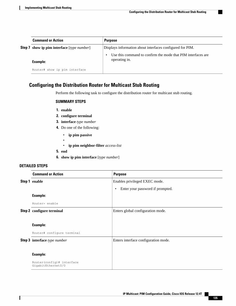
Command or Action Purpose
Step 7 show ip pim interface [type number]
Example:
Router# show ip pim interface
Displays information about interfaces configured for PIM.
• Use this command to confirm the mode that PIM interfaces areoperating in.
Configuring the Distribution Router for Multicast Stub RoutingPerform the following task to configure the distribution router for multicast stub routing.
SUMMARY STEPS
1. enable
2. configure terminal
3. interface type number
4. Do one of the following:
• ip pim passive•• ip pim neighbor-filter access-list
5. end
6. show ip pim interface [type number]
DETAILED STEPS
Command or Action Purpose
Step 1 enable
Example:
Router> enable
Enables privileged EXEC mode.
• Enter your password if prompted.
Step 2 configure terminal
Example:
Router# configure terminal
Enters global configuration mode.
Step 3 interface type number
Example:
Router(config)# interface GigabitEthernet0/0
Enters interface configuration mode.
Implementing Multicast Stub RoutingConfiguring the Distribution Router for Multicast Stub Routing
IP Multicast: PIM Configuration Guide, Cisco IOS Release 12.4T 135
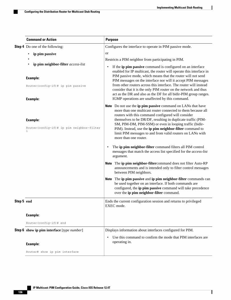
Command or Action Purpose
Step 4 Do one of the following:
• ip pim passive•• ip pim neighbor-filter access-list
Example:
Router(config-if)# ip pim passive
Example:
Example:
Router(config-if)# ip pim neighbor-filter 1
Configures the interface to operate in PIM passive mode.
or
Restricts a PIM neighbor from participating in PIM.
• If the ip pim passive command is configured on an interfaceenabled for IP multicast, the router will operate this interface inPIM passive mode, which means that the router will not sendPIM messages on the interface nor will it accept PIM messagesfrom other routers across this interface. The router will insteadconsider that it is the only PIM router on the network and thusact as the DR and also as the DF for all bidir-PIM group ranges.IGMP operations are unaffected by this command.
Note Do not use the ip pim passive command on LANs that havemore than one multicast router connected to them because allrouters with this command configured will considerthemselves to be DR/DF, resulting in duplicate traffic (PIM-SM, PIM-DM, PIM-SSM) or even in looping traffic (bidir-PIM). Instead, use the ip pim neighbor-filter command tolimit PIM messages to and from valid routers on LANs withmore than one router.
• The ip pim neighbor-filter command filters all PIM controlmessages that match the access list specified for the access-listargument.
Note The ip pim neighbor-filtercommand does not filter Auto-RPannouncements and is intended only to filter control messagesbetween PIM neighbors.
Note The ip pim passive and ip pim neighbor-filter commands canbe used together on an interface. If both commands areconfigured, the ip pim passive command will take precedenceover the ip pim neighbor-filter command.
Step 5 end
Example:
Router(config-if)# end
Ends the current configuration session and returns to privilegedEXEC mode.
Step 6 show ip pim interface [type number]
Example:
Router# show ip pim interface
Displays information about interfaces configured for PIM.
• Use this command to confirm the mode that PIM interfaces areoperating in.
Implementing Multicast Stub Routing Configuring the Distribution Router for Multicast Stub Routing
IP Multicast: PIM Configuration Guide, Cisco IOS Release 12.4T136
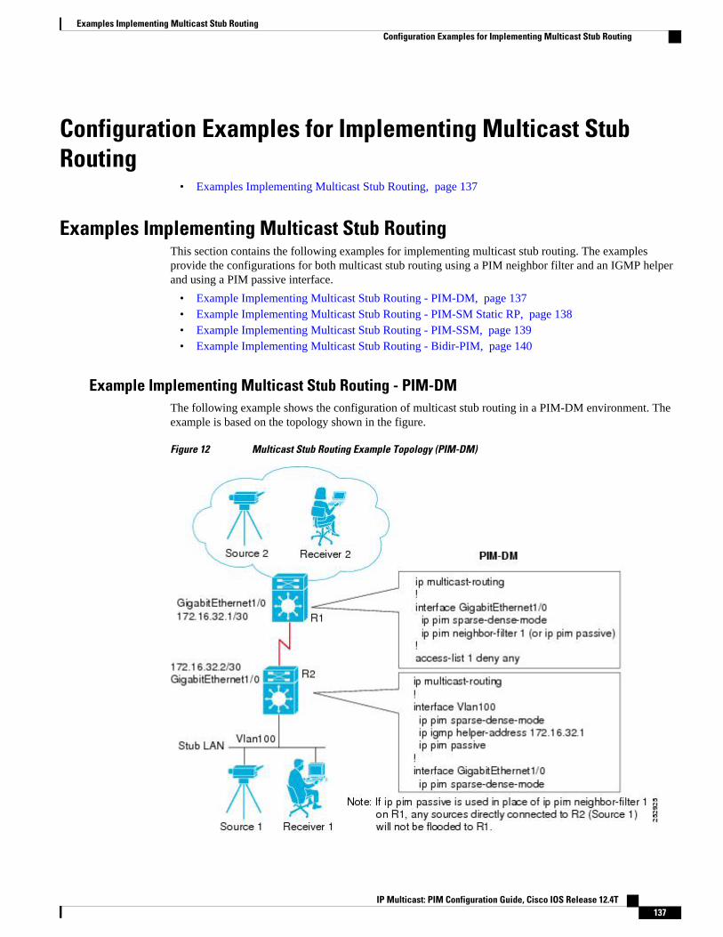
Configuration Examples for Implementing Multicast StubRouting
• Examples Implementing Multicast Stub Routing, page 137
Examples Implementing Multicast Stub RoutingThis section contains the following examples for implementing multicast stub routing. The examplesprovide the configurations for both multicast stub routing using a PIM neighbor filter and an IGMP helperand using a PIM passive interface.
• Example Implementing Multicast Stub Routing - PIM-DM, page 137• Example Implementing Multicast Stub Routing - PIM-SM Static RP, page 138• Example Implementing Multicast Stub Routing - PIM-SSM, page 139• Example Implementing Multicast Stub Routing - Bidir-PIM, page 140
Example Implementing Multicast Stub Routing - PIM-DMThe following example shows the configuration of multicast stub routing in a PIM-DM environment. Theexample is based on the topology shown in the figure.
Figure 12 Multicast Stub Routing Example Topology (PIM-DM)
Examples Implementing Multicast Stub RoutingConfiguration Examples for Implementing Multicast Stub Routing
IP Multicast: PIM Configuration Guide, Cisco IOS Release 12.4T 137
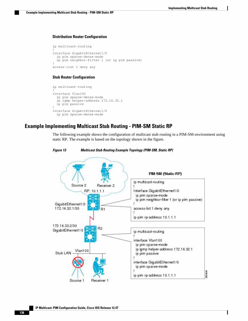
Distribution Router Configuration
ip multicast-routing!interface GigabitEthernet1/0 ip pim sparse-dense-mode ip pim neighbor-filter 1 (or ip pim passive)!access-list 1 deny any
Stub Router Configuration
ip multicast-routing!interface Vlan100 ip pim sparse-dense-mode ip igmp helper-address 172.16.32.1 ip pim passive!interface GigabitEthernet1/0 ip pim sparse-dense-mode
Example Implementing Multicast Stub Routing - PIM-SM Static RPThe following example shows the configuration of multicast stub routing in a PIM-SM environment usingstatic RP. The example is based on the topology shown in the figure.
Figure 13 Multicast Stub Routing Example Topology (PIM-SM, Static RP)
Implementing Multicast Stub Routing Example Implementing Multicast Stub Routing - PIM-SM Static RP
IP Multicast: PIM Configuration Guide, Cisco IOS Release 12.4T138
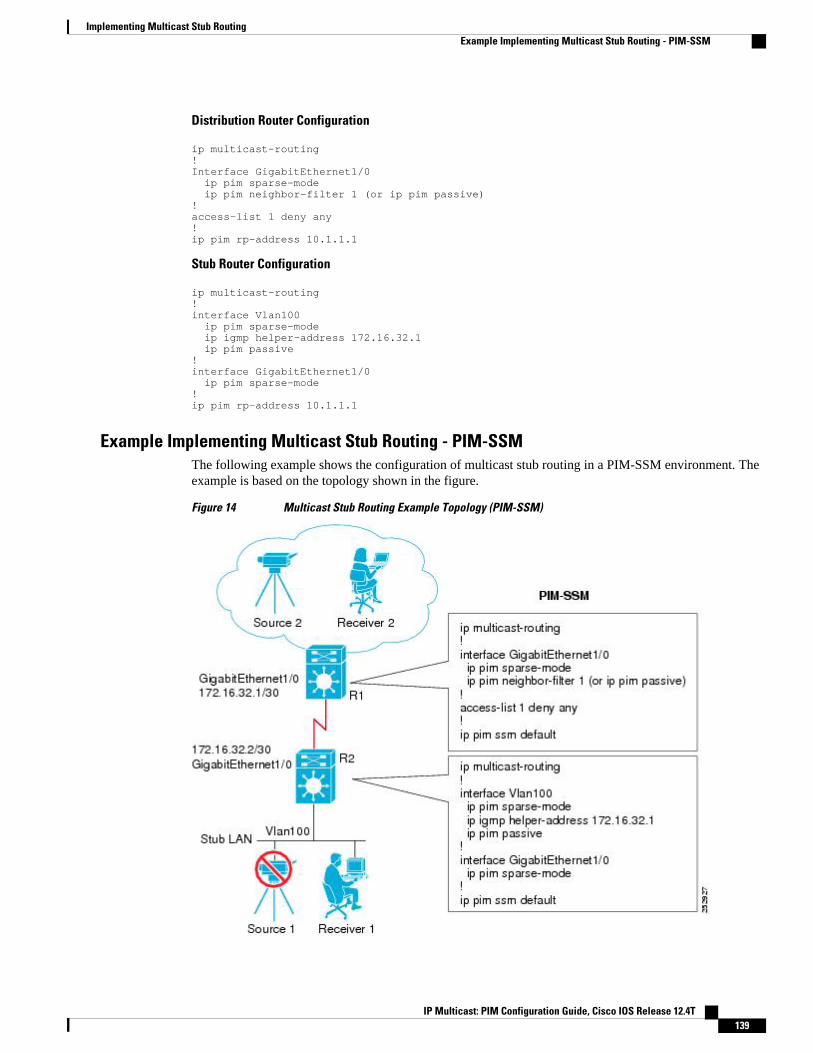
Distribution Router Configuration
ip multicast-routing!Interface GigabitEthernet1/0 ip pim sparse-mode ip pim neighbor-filter 1 (or ip pim passive)!access-list 1 deny any!ip pim rp-address 10.1.1.1
Stub Router Configuration
ip multicast-routing!interface Vlan100 ip pim sparse-mode ip igmp helper-address 172.16.32.1 ip pim passive!interface GigabitEthernet1/0 ip pim sparse-mode!ip pim rp-address 10.1.1.1
Example Implementing Multicast Stub Routing - PIM-SSMThe following example shows the configuration of multicast stub routing in a PIM-SSM environment. Theexample is based on the topology shown in the figure.
Figure 14 Multicast Stub Routing Example Topology (PIM-SSM)
Implementing Multicast Stub RoutingExample Implementing Multicast Stub Routing - PIM-SSM
IP Multicast: PIM Configuration Guide, Cisco IOS Release 12.4T 139
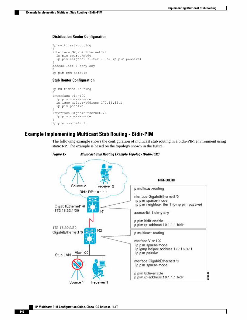
Distribution Router Configuration
ip multicast-routing!interface GigabitEthernet1/0 ip pim sparse-mode ip pim neighbor-filter 1 (or ip pim passive)!access-list 1 deny any!ip pim ssm default
Stub Router Configuration
ip multicast-routing!interface Vlan100 ip pim sparse-mode ip igmp helper-address 172.16.32.1 ip pim passive!interface GigabitEthernet1/0 ip pim sparse-mode!ip pim ssm default
Example Implementing Multicast Stub Routing - Bidir-PIMThe following example shows the configuration of multicast stub routing in a bidir-PIM environment usingstatic RP. The example is based on the topology shown in the figure.
Figure 15 Multicast Stub Routing Example Topology (Bidir-PIM)
Implementing Multicast Stub Routing Example Implementing Multicast Stub Routing - Bidir-PIM
IP Multicast: PIM Configuration Guide, Cisco IOS Release 12.4T140
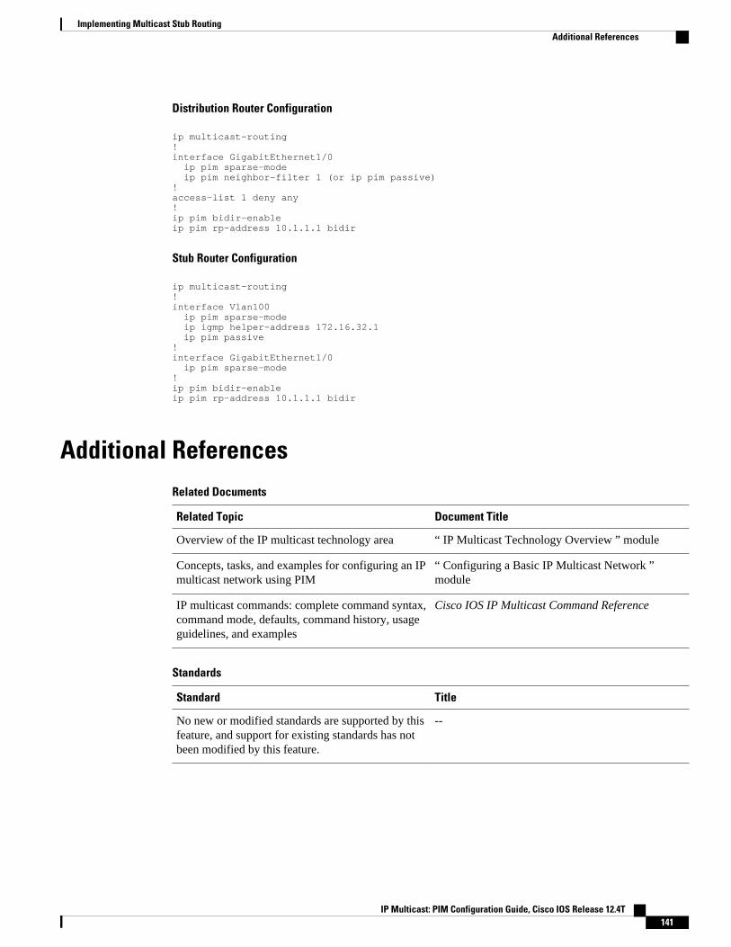
Distribution Router Configuration
ip multicast-routing!interface GigabitEthernet1/0 ip pim sparse-mode ip pim neighbor-filter 1 (or ip pim passive)!access-list 1 deny any!ip pim bidir-enableip pim rp-address 10.1.1.1 bidir
Stub Router Configuration
ip multicast-routing!interface Vlan100 ip pim sparse-mode ip igmp helper-address 172.16.32.1 ip pim passive!interface GigabitEthernet1/0 ip pim sparse-mode!ip pim bidir-enableip pim rp-address 10.1.1.1 bidir
Additional ReferencesRelated Documents
Related Topic Document Title
Overview of the IP multicast technology area “ IP Multicast Technology Overview ” module
Concepts, tasks, and examples for configuring an IPmulticast network using PIM
“ Configuring a Basic IP Multicast Network ”module
IP multicast commands: complete command syntax,command mode, defaults, command history, usageguidelines, and examples
Cisco IOS IP Multicast Command Reference
Standards
Standard Title
No new or modified standards are supported by thisfeature, and support for existing standards has notbeen modified by this feature.
--
Implementing Multicast Stub RoutingAdditional References
IP Multicast: PIM Configuration Guide, Cisco IOS Release 12.4T 141
MIBs
MIB MIBs Link
No new or modified MIBs are supported by thisfeature, and support for existing standards has notbeen modified by this feature.
To locate and download MIBs for selectedplatforms, Cisco software releases, and feature sets,use Cisco MIB Locator found at the followingURL:
http://www.cisco.com/go/mibs
RFCs
RFC Title
No new or modified RFCs are supported by thisfeature, and support for existing standards has notbeen modified by this feature.
--
Technical Assistance
Description Link
The Cisco Support website provides extensiveonline resources, including documentation and toolsfor troubleshooting and resolving technical issueswith Cisco products and technologies.
To receive security and technical information aboutyour products, you can subscribe to variousservices, such as the Product Alert Tool (accessedfrom Field Notices), the Cisco Technical ServicesNewsletter, and Really Simple Syndication (RSS)Feeds.
Access to most tools on the Cisco Support websiterequires a Cisco.com user ID and password.
http://www.cisco.com/cisco/web/support/index.html
Feature Information for Implementing Multicast Stub RoutingThe following table provides release information about the feature or features described in this module.This table lists only the software release that introduced support for a given feature in a given softwarerelease train. Unless noted otherwise, subsequent releases of that software release train also support thatfeature.
Use Cisco Feature Navigator to find information about platform support and Cisco software image support.To access Cisco Feature Navigator, go to www.cisco.com/go/cfn. An account on Cisco.com is not required.
Implementing Multicast Stub Routing Feature Information for Implementing Multicast Stub Routing
IP Multicast: PIM Configuration Guide, Cisco IOS Release 12.4T142
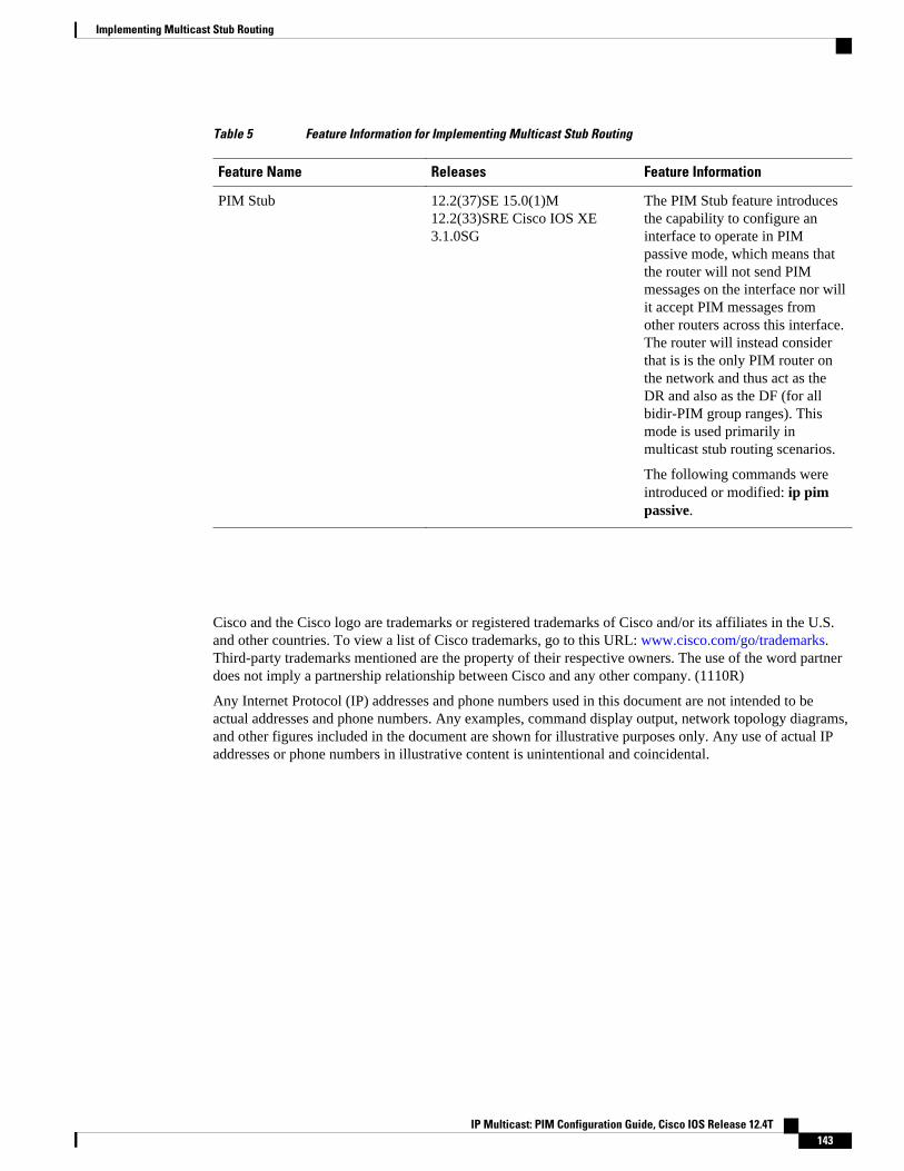
Table 5 Feature Information for Implementing Multicast Stub Routing
Feature Name Releases Feature Information
PIM Stub 12.2(37)SE 15.0(1)M12.2(33)SRE Cisco IOS XE3.1.0SG
The PIM Stub feature introducesthe capability to configure aninterface to operate in PIMpassive mode, which means thatthe router will not send PIMmessages on the interface nor willit accept PIM messages fromother routers across this interface.The router will instead considerthat is is the only PIM router onthe network and thus act as theDR and also as the DF (for allbidir-PIM group ranges). Thismode is used primarily inmulticast stub routing scenarios.
The following commands wereintroduced or modified: ip pimpassive.
Cisco and the Cisco logo are trademarks or registered trademarks of Cisco and/or its affiliates in the U.S.and other countries. To view a list of Cisco trademarks, go to this URL: www.cisco.com/go/trademarks.Third-party trademarks mentioned are the property of their respective owners. The use of the word partnerdoes not imply a partnership relationship between Cisco and any other company. (1110R)
Any Internet Protocol (IP) addresses and phone numbers used in this document are not intended to beactual addresses and phone numbers. Any examples, command display output, network topology diagrams,and other figures included in the document are shown for illustrative purposes only. Any use of actual IPaddresses or phone numbers in illustrative content is unintentional and coincidental.
Implementing Multicast Stub Routing
IP Multicast: PIM Configuration Guide, Cisco IOS Release 12.4T 143

Examples Implementing Multicast Stub Routing
IP Multicast: PIM Configuration Guide, Cisco IOS Release 12.4T144
Tunneling to Connect Non-IP Multicast Areas
This module describes how to configure a Generic Route Encapsulation (GRE) tunnel to tunnel IPmulticast packets between non-IP multicast areas. The benefit is that IP multicast traffic can be sent froma source to a multicast group, over an area where IP multicast is not supported.
• Finding Feature Information, page 145• Prerequisites for Tunneling to Connect Non-IP Multicast Areas, page 145• Information About Tunneling to Connect Non-IP Multicast Areas, page 145• How to Connect Non-IP Multicast Areas, page 146• Configuration Examples for Tunneling to Connect Non-IP Multicast Areas, page 150• Additional References, page 152• Feature Information for Tunneling to Connect Non-IP Multicast Areas, page 153
Finding Feature InformationYour software release may not support all the features documented in this module. For the latest featureinformation and caveats, see the release notes for your platform and software release. To find informationabout the features documented in this module, and to see a list of the releases in which each feature issupported, see the Feature Information Table at the end of this document.
Use Cisco Feature Navigator to find information about platform support and Cisco software image support.To access Cisco Feature Navigator, go to www.cisco.com/go/cfn. An account on Cisco.com is not required.
Prerequisites for Tunneling to Connect Non-IP MulticastAreas
This module assumes you understand the concepts in the “IP Multicast Technology Overview” module.
Information About Tunneling to Connect Non-IP MulticastAreas
• Benefits of Tunneling to Connect Non-IP Multicast Areas, page 146
• IP Multicast Static Route, page 146
IP Multicast: PIM Configuration Guide, Cisco IOS Release 12.4T 145
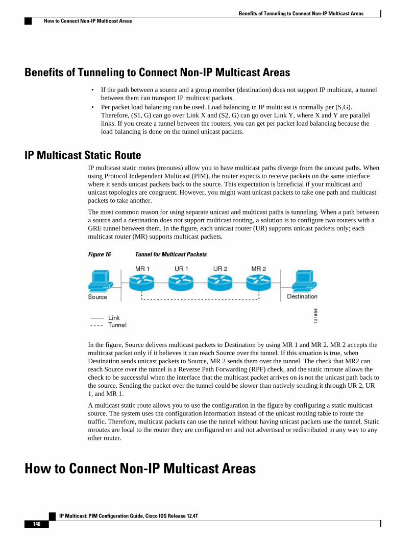
Benefits of Tunneling to Connect Non-IP Multicast Areas• If the path between a source and a group member (destination) does not support IP multicast, a tunnel
between them can transport IP multicast packets.• Per packet load balancing can be used. Load balancing in IP multicast is normally per (S,G).
Therefore, (S1, G) can go over Link X and (S2, G) can go over Link Y, where X and Y are parallellinks. If you create a tunnel between the routers, you can get per packet load balancing because theload balancing is done on the tunnel unicast packets.
IP Multicast Static RouteIP multicast static routes (mroutes) allow you to have multicast paths diverge from the unicast paths. Whenusing Protocol Independent Multicast (PIM), the router expects to receive packets on the same interfacewhere it sends unicast packets back to the source. This expectation is beneficial if your multicast andunicast topologies are congruent. However, you might want unicast packets to take one path and multicastpackets to take another.
The most common reason for using separate unicast and multicast paths is tunneling. When a path betweena source and a destination does not support multicast routing, a solution is to configure two routers with aGRE tunnel between them. In the figure, each unicast router (UR) supports unicast packets only; eachmulticast router (MR) supports multicast packets.
Figure 16 Tunnel for Multicast Packets
In the figure, Source delivers multicast packets to Destination by using MR 1 and MR 2. MR 2 accepts themulticast packet only if it believes it can reach Source over the tunnel. If this situation is true, whenDestination sends unicast packets to Source, MR 2 sends them over the tunnel. The check that MR2 canreach Source over the tunnel is a Reverse Path Forwarding (RPF) check, and the static mroute allows thecheck to be successful when the interface that the multicast packet arrives on is not the unicast path back tothe source. Sending the packet over the tunnel could be slower than natively sending it through UR 2, UR1, and MR 1.
A multicast static route allows you to use the configuration in the figure by configuring a static multicastsource. The system uses the configuration information instead of the unicast routing table to route thetraffic. Therefore, multicast packets can use the tunnel without having unicast packets use the tunnel. Staticmroutes are local to the router they are configured on and not advertised or redistributed in any way to anyother router.
How to Connect Non-IP Multicast Areas
Benefits of Tunneling to Connect Non-IP Multicast Areas How to Connect Non-IP Multicast Areas
IP Multicast: PIM Configuration Guide, Cisco IOS Release 12.4T146

• Configuring a Tunnel to Connect Non-IP Multicast Areas, page 147
Configuring a Tunnel to Connect Non-IP Multicast AreasConfigure a multicast static route if you want your multicast paths to differ from your unicast paths. Forexample, you might have a tunnel between two routers because the unicast path between a source anddestination does not support multicast routing.
SUMMARY STEPS
1. enable
2. configure terminal
3. interface tunnel number
4. ip unnumbered type number
5. ip pim sparse-mode
6. tunnel source {ip-address | type number}
7. tunnel destination {hostname | ip-address}
8. Repeat Steps 1 through 7 on the router at the opposite end of the tunnel, reversing the tunnel source anddestination addresses.
9. end
10. ip mroute source-address mask tunnel number [distance]
11. ip mroute source-address mask tunnel number [distance]
12. end
13. show ip mroute [group-address | group-name] [source-address | source-name] [interface-typeinterface-number] [summary] [count] [active kbps]
14. show ip rpf {source-address | source-name} [metric]
DETAILED STEPS
Command or Action Purpose
Step 1 enable
Example:
Router> enable
Enables privileged EXEC mode.
• Enter your password if prompted.
Step 2 configure terminal
Example:
Router# configure terminal
Enters global configuration mode.
Configuring a Tunnel to Connect Non-IP Multicast AreasHow to Connect Non-IP Multicast Areas
IP Multicast: PIM Configuration Guide, Cisco IOS Release 12.4T 147
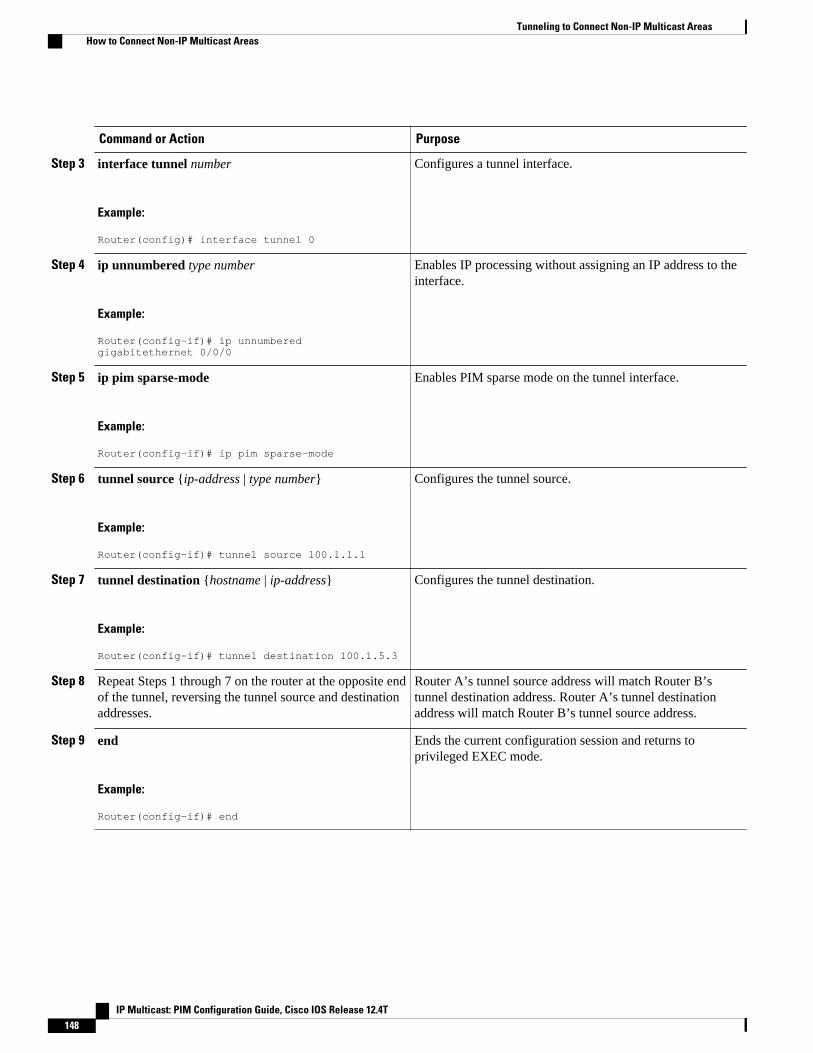
Command or Action Purpose
Step 3 interface tunnel number
Example:
Router(config)# interface tunnel 0
Configures a tunnel interface.
Step 4 ip unnumbered type number
Example:
Router(config-if)# ip unnumbered gigabitethernet 0/0/0
Enables IP processing without assigning an IP address to theinterface.
Step 5 ip pim sparse-mode
Example:
Router(config-if)# ip pim sparse-mode
Enables PIM sparse mode on the tunnel interface.
Step 6 tunnel source {ip-address | type number}
Example:
Router(config-if)# tunnel source 100.1.1.1
Configures the tunnel source.
Step 7 tunnel destination {hostname | ip-address}
Example:
Router(config-if)# tunnel destination 100.1.5.3
Configures the tunnel destination.
Step 8 Repeat Steps 1 through 7 on the router at the opposite endof the tunnel, reversing the tunnel source and destinationaddresses.
Router A’s tunnel source address will match Router B’stunnel destination address. Router A’s tunnel destinationaddress will match Router B’s tunnel source address.
Step 9 end
Example:
Router(config-if)# end
Ends the current configuration session and returns toprivileged EXEC mode.
Tunneling to Connect Non-IP Multicast Areas How to Connect Non-IP Multicast Areas
IP Multicast: PIM Configuration Guide, Cisco IOS Release 12.4T148
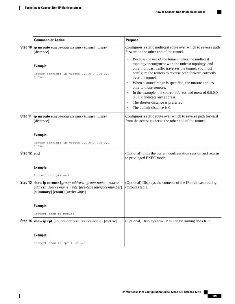
Command or Action Purpose
Step 10 ip mroute source-address mask tunnel number[distance]
Example:
Router(config)# ip mroute 0.0.0.0 0.0.0.0 tunnel 0
Configures a static multicast route over which to reverse pathforward to the other end of the tunnel.
• Because the use of the tunnel makes the multicasttopology incongruent with the unicast topology, andonly multicast traffic traverses the tunnel, you mustconfigure the routers to reverse path forward correctlyover the tunnel.
• When a source range is specified, the mroute appliesonly to those sources.
• In the example, the source-address and mask of 0.0.0.00.0.0.0 indicate any address.
• The shorter distance is preferred.• The default distance is 0.
Step 11 ip mroute source-address mask tunnel number[distance]
Example:
Router(config)# ip mroute 0.0.0.0 0.0.0.0 tunnel 0
Configures a static route over which to reverse path forwardfrom the access router to the other end of the tunnel.
Step 12 end
Example:
Router(config)# end
(Optional) Ends the current configuration session and returnsto privileged EXEC mode.
Step 13 show ip mroute [group-address | group-name] [source-address | source-name] [interface-type interface-number][summary] [count] [active kbps]
Example:
Router# show ip mroute
(Optional) Displays the contents of the IP multicast routing(mroute) table.
Step 14 show ip rpf {source-address | source-name} [metric]
Example:
Router# show ip rpf 10.2.3.4
(Optional) Displays how IP multicast routing does RPF.
Tunneling to Connect Non-IP Multicast AreasHow to Connect Non-IP Multicast Areas
IP Multicast: PIM Configuration Guide, Cisco IOS Release 12.4T 149
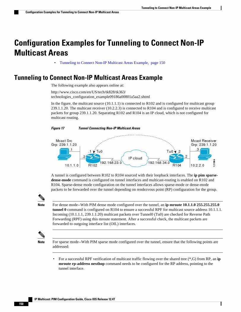
Configuration Examples for Tunneling to Connect Non-IPMulticast Areas
• Tunneling to Connect Non-IP Multicast Areas Example, page 150
Tunneling to Connect Non-IP Multicast Areas ExampleThe following example also appears online at:
http://www.cisco.com/en/US/tech/tk828/tk363/technologies_configuration_example09186a00801a5aa2.shtml
In the figure, the multicast source (10.1.1.1) is connected to R102 and is configured for multicast group239.1.1.20. The multicast receiver (10.2.2.3) is connected to R104 and is configured to receive multicastpackets for group 239.1.1.20. Separating R102 and R104 is an IP cloud, which is not configured formulticast routing.
Figure 17 Tunnel Connecting Non-IP Multicast Areas
A tunnel is configured between R102 to R104 sourced with their loopback interfaces. The ip pim sparse-dense-mode command is configured on tunnel interfaces and multicast-routing is enabled on R102 andR104. Sparse-dense mode configuration on the tunnel interfaces allows sparse-mode or dense-modepackets to be forwarded over the tunnel depending on rendezvous point (RP) configuration for the group.
Note For dense mode--With PIM dense mode configured over the tunnel, an ip mroute 10.1.1.0 255.255.255.0tunnel 0 command is configured on R104 to ensure a successful RPF for multicast source address 10.1.1.1.Incoming (10.1.1.1, 239.1.1.20) multicast packets over Tunnel0 (Tu0) are checked for Reverse PathForwarding (RPF) using this mroute statement. After a successful check, the multicast packets areforwarded to outgoing interface list (OIL) interfaces.
Note For sparse mode--With PIM sparse mode configured over the tunnel, ensure that the following points areaddressed:
• For a successful RPF verification of multicast traffic flowing over the shared tree (*,G) from RP, an ipmroute rp-address nexthop command needs to be configured for the RP address, pointing to thetunnel interface.
Tunneling to Connect Non-IP Multicast Areas Example Configuration Examples for Tunneling to Connect Non-IP Multicast Areas
IP Multicast: PIM Configuration Guide, Cisco IOS Release 12.4T150
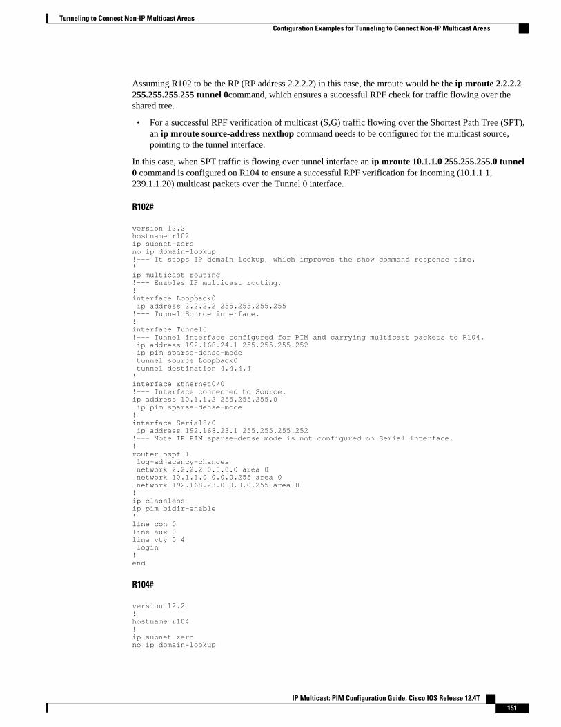
Assuming R102 to be the RP (RP address 2.2.2.2) in this case, the mroute would be the ip mroute 2.2.2.2255.255.255.255 tunnel 0command, which ensures a successful RPF check for traffic flowing over theshared tree.
• For a successful RPF verification of multicast (S,G) traffic flowing over the Shortest Path Tree (SPT),an ip mroute source-address nexthop command needs to be configured for the multicast source,pointing to the tunnel interface.
In this case, when SPT traffic is flowing over tunnel interface an ip mroute 10.1.1.0 255.255.255.0 tunnel0 command is configured on R104 to ensure a successful RPF verification for incoming (10.1.1.1,239.1.1.20) multicast packets over the Tunnel 0 interface.
R102#
version 12.2hostname r102ip subnet-zerono ip domain-lookup!--- It stops IP domain lookup, which improves the show command response time.!ip multicast-routing!--- Enables IP multicast routing.!interface Loopback0 ip address 2.2.2.2 255.255.255.255!--- Tunnel Source interface.!interface Tunnel0!--- Tunnel interface configured for PIM and carrying multicast packets to R104. ip address 192.168.24.1 255.255.255.252 ip pim sparse-dense-mode tunnel source Loopback0 tunnel destination 4.4.4.4!interface Ethernet0/0!--- Interface connected to Source.ip address 10.1.1.2 255.255.255.0 ip pim sparse-dense-mode!interface Serial8/0 ip address 192.168.23.1 255.255.255.252!--- Note IP PIM sparse-dense mode is not configured on Serial interface.!router ospf 1 log-adjacency-changes network 2.2.2.2 0.0.0.0 area 0 network 10.1.1.0 0.0.0.255 area 0 network 192.168.23.0 0.0.0.255 area 0!ip classlessip pim bidir-enable! line con 0line aux 0line vty 0 4 login!end
R104#
version 12.2!hostname r104!ip subnet-zerono ip domain-lookup
Tunneling to Connect Non-IP Multicast AreasConfiguration Examples for Tunneling to Connect Non-IP Multicast Areas
IP Multicast: PIM Configuration Guide, Cisco IOS Release 12.4T 151
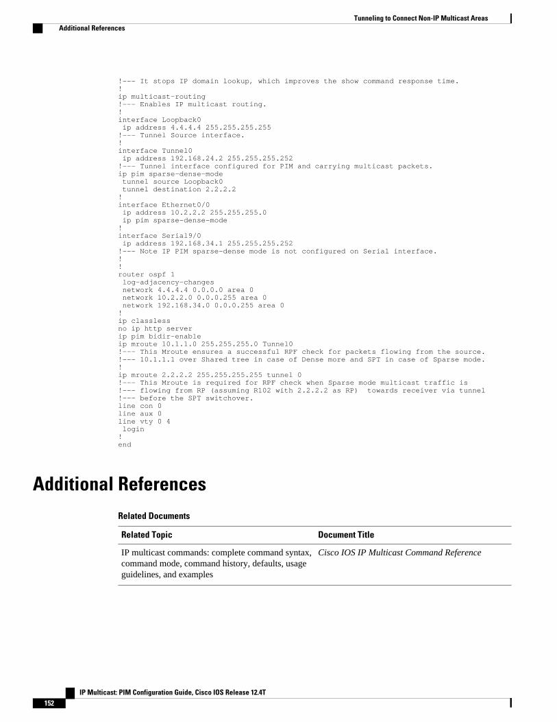
!--- It stops IP domain lookup, which improves the show command response time.!ip multicast-routing!--- Enables IP multicast routing.!interface Loopback0 ip address 4.4.4.4 255.255.255.255!--- Tunnel Source interface.!interface Tunnel0 ip address 192.168.24.2 255.255.255.252!--- Tunnel interface configured for PIM and carrying multicast packets.ip pim sparse-dense-mode tunnel source Loopback0 tunnel destination 2.2.2.2!interface Ethernet0/0 ip address 10.2.2.2 255.255.255.0 ip pim sparse-dense-mode!interface Serial9/0 ip address 192.168.34.1 255.255.255.252!--- Note IP PIM sparse-dense mode is not configured on Serial interface.!!router ospf 1 log-adjacency-changes network 4.4.4.4 0.0.0.0 area 0 network 10.2.2.0 0.0.0.255 area 0 network 192.168.34.0 0.0.0.255 area 0!ip classlessno ip http serverip pim bidir-enableip mroute 10.1.1.0 255.255.255.0 Tunnel0!--- This Mroute ensures a successful RPF check for packets flowing from the source.!--- 10.1.1.1 over Shared tree in case of Dense more and SPT in case of Sparse mode.!ip mroute 2.2.2.2 255.255.255.255 tunnel 0!--- This Mroute is required for RPF check when Sparse mode multicast traffic is !--- flowing from RP (assuming R102 with 2.2.2.2 as RP) towards receiver via tunnel !--- before the SPT switchover.line con 0line aux 0line vty 0 4 login!end
Additional ReferencesRelated Documents
Related Topic Document Title
IP multicast commands: complete command syntax,command mode, command history, defaults, usageguidelines, and examples
Cisco IOS IP Multicast Command Reference
Tunneling to Connect Non-IP Multicast Areas Additional References
IP Multicast: PIM Configuration Guide, Cisco IOS Release 12.4T152
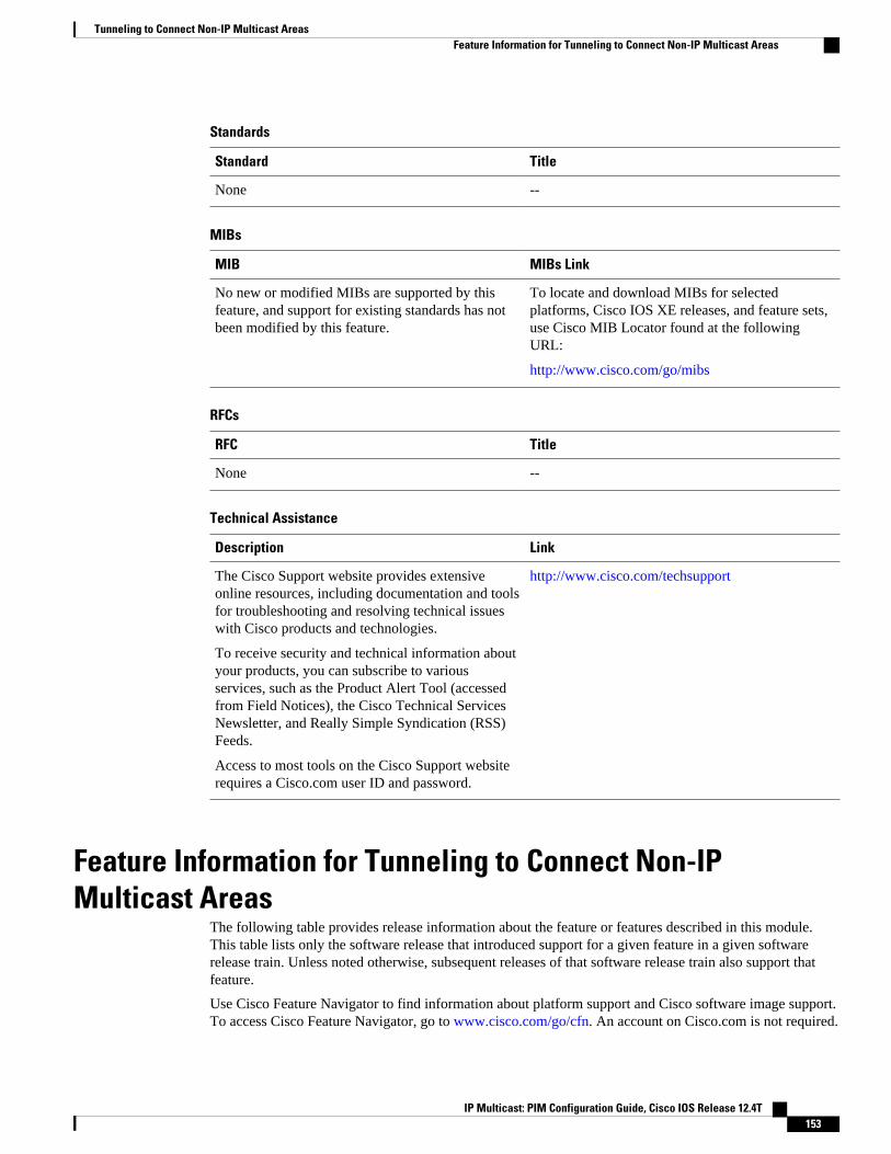
Standards
Standard Title
None --
MIBs
MIB MIBs Link
No new or modified MIBs are supported by thisfeature, and support for existing standards has notbeen modified by this feature.
To locate and download MIBs for selectedplatforms, Cisco IOS XE releases, and feature sets,use Cisco MIB Locator found at the followingURL:
http://www.cisco.com/go/mibs
RFCs
RFC Title
None --
Technical Assistance
Description Link
The Cisco Support website provides extensiveonline resources, including documentation and toolsfor troubleshooting and resolving technical issueswith Cisco products and technologies.
To receive security and technical information aboutyour products, you can subscribe to variousservices, such as the Product Alert Tool (accessedfrom Field Notices), the Cisco Technical ServicesNewsletter, and Really Simple Syndication (RSS)Feeds.
Access to most tools on the Cisco Support websiterequires a Cisco.com user ID and password.
http://www.cisco.com/techsupport
Feature Information for Tunneling to Connect Non-IPMulticast Areas
The following table provides release information about the feature or features described in this module.This table lists only the software release that introduced support for a given feature in a given softwarerelease train. Unless noted otherwise, subsequent releases of that software release train also support thatfeature.
Use Cisco Feature Navigator to find information about platform support and Cisco software image support.To access Cisco Feature Navigator, go to www.cisco.com/go/cfn. An account on Cisco.com is not required.
Tunneling to Connect Non-IP Multicast AreasFeature Information for Tunneling to Connect Non-IP Multicast Areas
IP Multicast: PIM Configuration Guide, Cisco IOS Release 12.4T 153
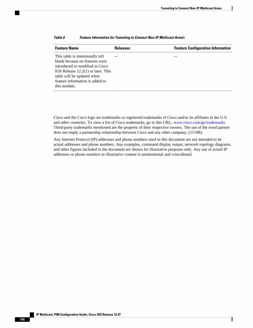
Table 6 Feature Information for Tunneling to Connect Non-IP Multicast Areas\
Feature Name Releases Feature Configuration Information
This table is intentionally leftblank because no features wereintroduced or modified in CiscoIOS Release 12.2(1) or later. Thistable will be updated whenfeature information is added tothis module.
-- --
Cisco and the Cisco logo are trademarks or registered trademarks of Cisco and/or its affiliates in the U.S.and other countries. To view a list of Cisco trademarks, go to this URL: www.cisco.com/go/trademarks.Third-party trademarks mentioned are the property of their respective owners. The use of the word partnerdoes not imply a partnership relationship between Cisco and any other company. (1110R)
Any Internet Protocol (IP) addresses and phone numbers used in this document are not intended to beactual addresses and phone numbers. Any examples, command display output, network topology diagrams,and other figures included in the document are shown for illustrative purposes only. Any use of actual IPaddresses or phone numbers in illustrative content is unintentional and coincidental.
Tunneling to Connect Non-IP Multicast Areas
IP Multicast: PIM Configuration Guide, Cisco IOS Release 12.4T154
Verifying IP Multicast Operation
This module describes how to verify IP multicast operation in a network after Protocol IndependentMulticast (PIM) sparse mode (PIM-SM) or Source Specific Multicast (PIM-SSM) has been implemented.The tasks in this module can be used to test IP multicast reachability and to confirm that receivers andsources are operating as expected in an IP multicast network.
• Finding Feature Information, page 155• Prerequisites for Verifying IP Multicast Operation, page 155• Restrictions for Verifying IP Multicast Operation, page 155• Information About Verifying IP Multicast Operation, page 156• How to Verify IP Multicast Operation, page 159• Configuration Examples for Verifying IP Multicast Operation, page 167• Additional References, page 172• Feature Information for Verifying IP Multicast Operation, page 173
Finding Feature InformationYour software release may not support all the features documented in this module. For the latest featureinformation and caveats, see the release notes for your platform and software release. To find informationabout the features documented in this module, and to see a list of the releases in which each feature issupported, see the Feature Information Table at the end of this document.
Use Cisco Feature Navigator to find information about platform support and Cisco software image support.To access Cisco Feature Navigator, go to www.cisco.com/go/cfn. An account on Cisco.com is not required.
Prerequisites for Verifying IP Multicast Operation• Before performing the tasks in this module, you should be familiar with the concepts described in the
“ IP Multicast Technology Overview ” module.• The tasks in this module assume that IP multicast has been enabled and that PIM-SM or SSM has been
configured using the relevant tasks described in the “ Configuring Basic IP Multicast ” module.
Restrictions for Verifying IP Multicast Operation• For PIM-SM, this module assumes that the shortest path tree (SPT) threshold for PIM-enabled routers
is set to the value of zero (the default) and not infinity. For more information about setting the SPT
IP Multicast: PIM Configuration Guide, Cisco IOS Release 12.4T 155
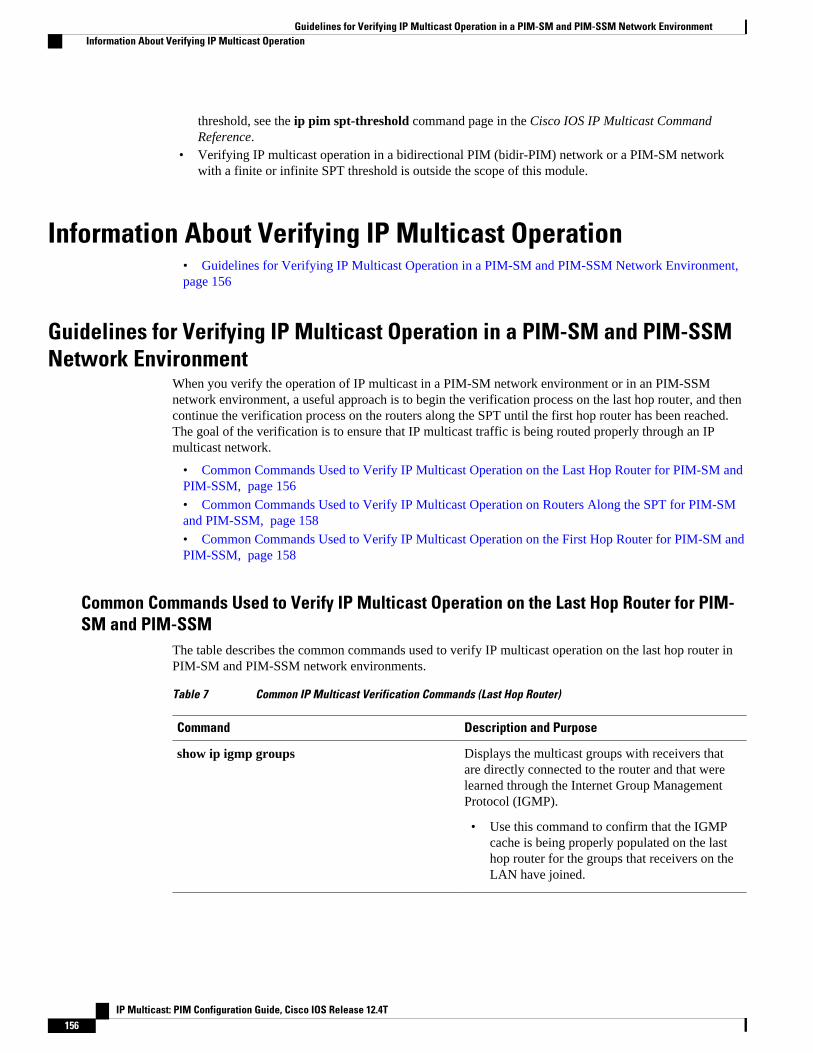
threshold, see the ip pim spt-threshold command page in the Cisco IOS IP Multicast CommandReference.
• Verifying IP multicast operation in a bidirectional PIM (bidir-PIM) network or a PIM-SM networkwith a finite or infinite SPT threshold is outside the scope of this module.
Information About Verifying IP Multicast Operation• Guidelines for Verifying IP Multicast Operation in a PIM-SM and PIM-SSM Network Environment, page 156
Guidelines for Verifying IP Multicast Operation in a PIM-SM and PIM-SSMNetwork Environment
When you verify the operation of IP multicast in a PIM-SM network environment or in an PIM-SSMnetwork environment, a useful approach is to begin the verification process on the last hop router, and thencontinue the verification process on the routers along the SPT until the first hop router has been reached.The goal of the verification is to ensure that IP multicast traffic is being routed properly through an IPmulticast network.
• Common Commands Used to Verify IP Multicast Operation on the Last Hop Router for PIM-SM andPIM-SSM, page 156
• Common Commands Used to Verify IP Multicast Operation on Routers Along the SPT for PIM-SMand PIM-SSM, page 158
• Common Commands Used to Verify IP Multicast Operation on the First Hop Router for PIM-SM andPIM-SSM, page 158
Common Commands Used to Verify IP Multicast Operation on the Last Hop Router for PIM-SM and PIM-SSM
The table describes the common commands used to verify IP multicast operation on the last hop router inPIM-SM and PIM-SSM network environments.
Table 7 Common IP Multicast Verification Commands (Last Hop Router)
Command Description and Purpose
show ip igmp groups Displays the multicast groups with receivers thatare directly connected to the router and that werelearned through the Internet Group ManagementProtocol (IGMP).
• Use this command to confirm that the IGMPcache is being properly populated on the lasthop router for the groups that receivers on theLAN have joined.
Guidelines for Verifying IP Multicast Operation in a PIM-SM and PIM-SSM Network Environment Information About Verifying IP Multicast Operation
IP Multicast: PIM Configuration Guide, Cisco IOS Release 12.4T156

Command Description and Purpose
show ip pim rp mapping Displays all group-to-RP mappings of which therouter is aware (either configured or learned fromAuto-RP or BSR).
• Use this command to confirm that the group-to-RP mappings are being populated correctlyon the last hop router.
Note The show ip pim rp mappingcommanddoes not work with routers in a PIM-SSMnetwork because PIM-SSM does not userendezvous points (RPs).
show ip mroute Displays the contents of the multicast routing(mroute) table.
• Use this command to verify that the mroutetable is being populated properly on the lasthop router.
show ip interface Displays information and statistics aboutconfigured interfaces.
• Use this command to verify that IP multicastfast switching is enabled on the outgoinginterface on the last hop router.
show ip mfib Displays the forwarding entries and interfaces inthe IP Multicast Forwarding Information Base(MFIB).
show ip pim interface count Displays statistics related to the number ofmulticast packets received by and sent out a PIM-enabled interface.
• Use this command on the last hop router toconfirm that multicast traffic is beingforwarded on the last hop router.
show ip mroute active Displays the rate that active sources are sending tomulticast groups, in kilobits per second (kb/s).
• Use this command to display informationabout the multicast packet rate for activesources sending to groups on the last hoprouter.
Verifying IP Multicast OperationCommon Commands Used to Verify IP Multicast Operation on the Last Hop Router for PIM-SM and PIM-SSM
IP Multicast: PIM Configuration Guide, Cisco IOS Release 12.4T 157
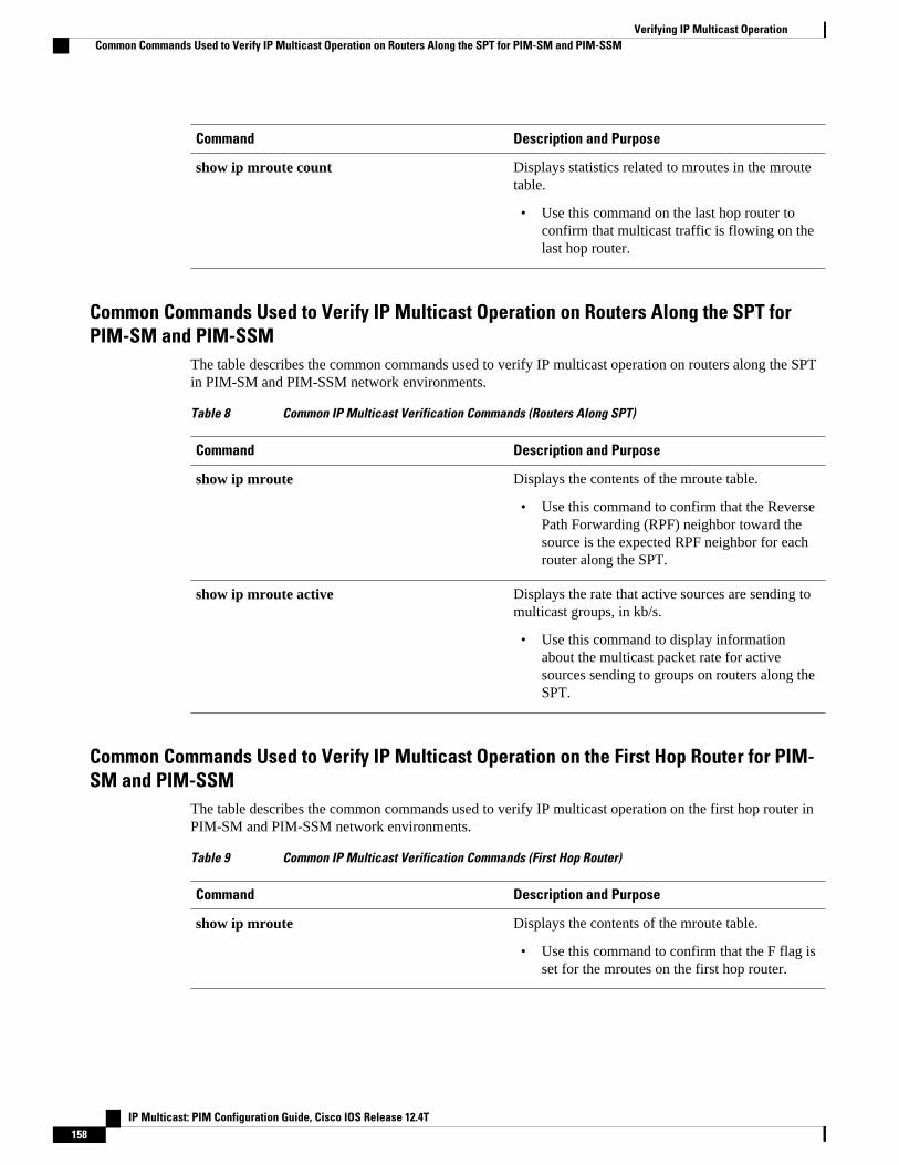
Command Description and Purpose
show ip mroute count Displays statistics related to mroutes in the mroutetable.
• Use this command on the last hop router toconfirm that multicast traffic is flowing on thelast hop router.
Common Commands Used to Verify IP Multicast Operation on Routers Along the SPT forPIM-SM and PIM-SSM
The table describes the common commands used to verify IP multicast operation on routers along the SPTin PIM-SM and PIM-SSM network environments.
Table 8 Common IP Multicast Verification Commands (Routers Along SPT)
Command Description and Purpose
show ip mroute Displays the contents of the mroute table.
• Use this command to confirm that the ReversePath Forwarding (RPF) neighbor toward thesource is the expected RPF neighbor for eachrouter along the SPT.
show ip mroute active Displays the rate that active sources are sending tomulticast groups, in kb/s.
• Use this command to display informationabout the multicast packet rate for activesources sending to groups on routers along theSPT.
Common Commands Used to Verify IP Multicast Operation on the First Hop Router for PIM-SM and PIM-SSM
The table describes the common commands used to verify IP multicast operation on the first hop router inPIM-SM and PIM-SSM network environments.
Table 9 Common IP Multicast Verification Commands (First Hop Router)
Command Description and Purpose
show ip mroute Displays the contents of the mroute table.
• Use this command to confirm that the F flag isset for the mroutes on the first hop router.
Verifying IP Multicast Operation Common Commands Used to Verify IP Multicast Operation on Routers Along the SPT for PIM-SM and PIM-SSM
IP Multicast: PIM Configuration Guide, Cisco IOS Release 12.4T158
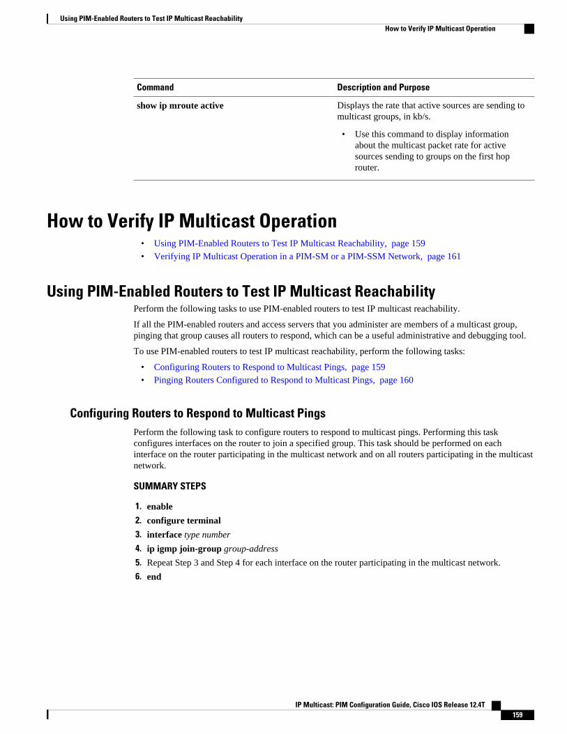
Command Description and Purpose
show ip mroute active Displays the rate that active sources are sending tomulticast groups, in kb/s.
• Use this command to display informationabout the multicast packet rate for activesources sending to groups on the first hoprouter.
How to Verify IP Multicast Operation• Using PIM-Enabled Routers to Test IP Multicast Reachability, page 159
• Verifying IP Multicast Operation in a PIM-SM or a PIM-SSM Network, page 161
Using PIM-Enabled Routers to Test IP Multicast ReachabilityPerform the following tasks to use PIM-enabled routers to test IP multicast reachability.
If all the PIM-enabled routers and access servers that you administer are members of a multicast group,pinging that group causes all routers to respond, which can be a useful administrative and debugging tool.
To use PIM-enabled routers to test IP multicast reachability, perform the following tasks:
• Configuring Routers to Respond to Multicast Pings, page 159
• Pinging Routers Configured to Respond to Multicast Pings, page 160
Configuring Routers to Respond to Multicast PingsPerform the following task to configure routers to respond to multicast pings. Performing this taskconfigures interfaces on the router to join a specified group. This task should be performed on eachinterface on the router participating in the multicast network and on all routers participating in the multicastnetwork.
SUMMARY STEPS
1. enable
2. configure terminal
3. interface type number
4. ip igmp join-group group-address
5. Repeat Step 3 and Step 4 for each interface on the router participating in the multicast network.
6. end
Using PIM-Enabled Routers to Test IP Multicast ReachabilityHow to Verify IP Multicast Operation
IP Multicast: PIM Configuration Guide, Cisco IOS Release 12.4T 159
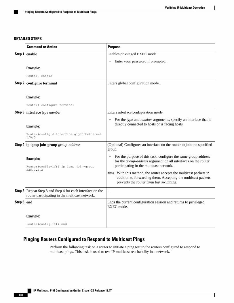
DETAILED STEPS
Command or Action Purpose
Step 1 enable
Example:
Router> enable
Enables privileged EXEC mode.
• Enter your password if prompted.
Step 2 configure terminal
Example:
Router# configure terminal
Enters global configuration mode.
Step 3 interface type number
Example:
Router(config)# interface gigabitethernet 1/0/0
Enters interface configuration mode.
• For the type and number arguments, specify an interface that isdirectly connected to hosts or is facing hosts.
Step 4 ip igmp join-group group-address
Example:
Router(config-if)# ip igmp join-group 225.2.2.2
(Optional) Configures an interface on the router to join the specifiedgroup.
• For the purpose of this task, configure the same group addressfor the group-address argument on all interfaces on the routerparticipating in the multicast network.
Note With this method, the router accepts the multicast packets inaddition to forwarding them. Accepting the multicast packetsprevents the router from fast switching.
Step 5 Repeat Step 3 and Step 4 for each interface on therouter participating in the multicast network.
--
Step 6 end
Example:
Router(config-if)# end
Ends the current configuration session and returns to privilegedEXEC mode.
Pinging Routers Configured to Respond to Multicast PingsPerform the following task on a router to initiate a ping test to the routers configured to respond tomulticast pings. This task is used to test IP multicast reachability in a network.
Verifying IP Multicast Operation Pinging Routers Configured to Respond to Multicast Pings
IP Multicast: PIM Configuration Guide, Cisco IOS Release 12.4T160
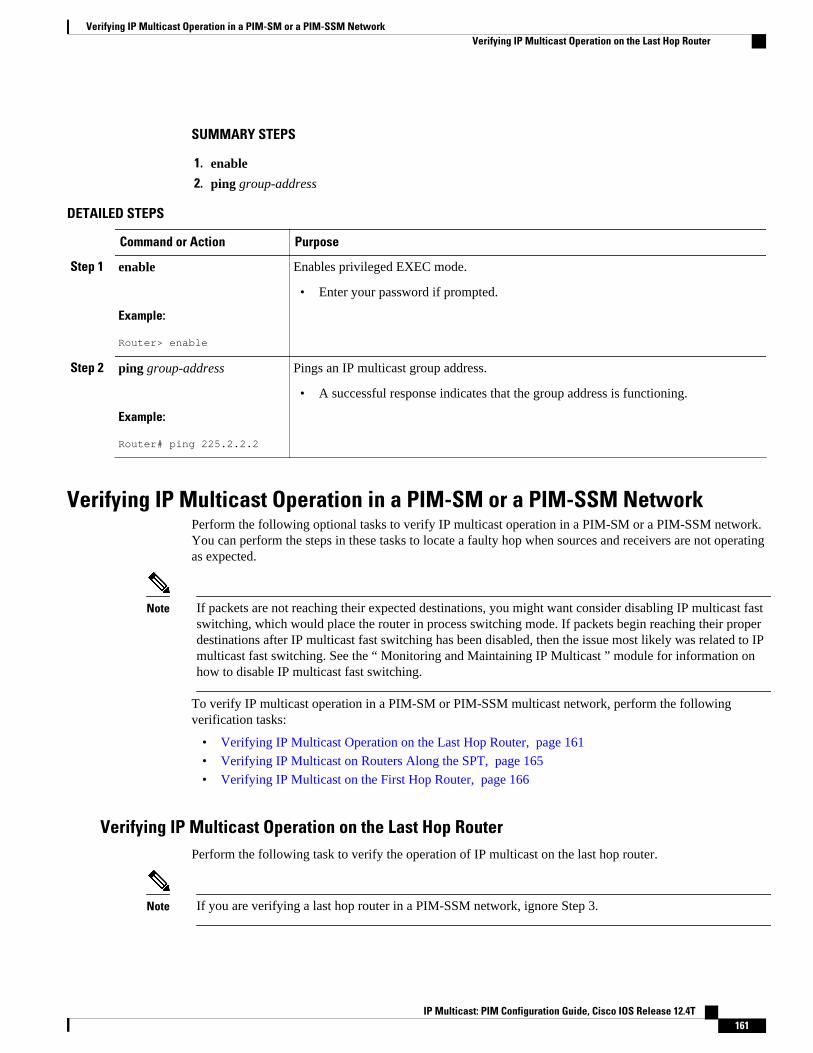
SUMMARY STEPS
1. enable
2. ping group-address
DETAILED STEPS
Command or Action Purpose
Step 1 enable
Example:
Router> enable
Enables privileged EXEC mode.
• Enter your password if prompted.
Step 2 ping group-address
Example:
Router# ping 225.2.2.2
Pings an IP multicast group address.
• A successful response indicates that the group address is functioning.
Verifying IP Multicast Operation in a PIM-SM or a PIM-SSM NetworkPerform the following optional tasks to verify IP multicast operation in a PIM-SM or a PIM-SSM network.You can perform the steps in these tasks to locate a faulty hop when sources and receivers are not operatingas expected.
Note If packets are not reaching their expected destinations, you might want consider disabling IP multicast fastswitching, which would place the router in process switching mode. If packets begin reaching their properdestinations after IP multicast fast switching has been disabled, then the issue most likely was related to IPmulticast fast switching. See the “ Monitoring and Maintaining IP Multicast ” module for information onhow to disable IP multicast fast switching.
To verify IP multicast operation in a PIM-SM or PIM-SSM multicast network, perform the followingverification tasks:
• Verifying IP Multicast Operation on the Last Hop Router, page 161
• Verifying IP Multicast on Routers Along the SPT, page 165
• Verifying IP Multicast on the First Hop Router, page 166
Verifying IP Multicast Operation on the Last Hop RouterPerform the following task to verify the operation of IP multicast on the last hop router.
Note If you are verifying a last hop router in a PIM-SSM network, ignore Step 3.
Verifying IP Multicast Operation in a PIM-SM or a PIM-SSM NetworkVerifying IP Multicast Operation on the Last Hop Router
IP Multicast: PIM Configuration Guide, Cisco IOS Release 12.4T 161

SUMMARY STEPS
1. enable
2. show ip igmp groups
3. show ip pim rp mapping
4. show ip mroute
5. show ip interface [type number]
6. show ip mfib
7. show ip pim interface count
8. show ip mroute count
9. show ip mroute active [kb/s]
DETAILED STEPS
Step 1 enableEnables privileged EXEC mode. Enter your password if prompted.
Router> enable
Step 2 show ip igmp groupsUse this command to verify IGMP memberships on the last hop router. This information will confirm the multicastgroups with receivers that are directly connected to the last hop router and that are learned through IGMP.
The following is sample output from the show ip igmp groups command:
Example:
Router# show ip igmp groupsIGMP Connected Group MembershipGroup Address Interface Uptime Expires Last Reporter239.1.2.3 GigabitEthernet1/0/0 00:05:14 00:02:14 10.1.0.6224.0.1.39 GigabitEthernet0/0/0 00:09:11 00:02:08 172.31.100.1
Step 3 show ip pim rp mappingUse this command to confirm that the group-to-RP mappings are being populated correctly on the last hop router.
Note Ignore this step if you are verifying a last hop router in a PIM-SSM network. The show ip pim rpmappingcommand does not work with routers in a PIM-SSM network because PIM-SSM does not use RPs. Inaddition, if configured correctly, PIM-SSM groups should not appear in the output of the show ip pim rpmappingcommand.
The following is sample output from the show ip pim rp mappingcommand:
Example:
Router# show ip pim rp mappingPIM Group-to-RP Mappings Group(s) 224.0.0.0/4 RP 172.16.0.1 (?), v2v1
Verifying IP Multicast Operation Verifying IP Multicast Operation on the Last Hop Router
IP Multicast: PIM Configuration Guide, Cisco IOS Release 12.4T162

Info source: 172.16.0.1 (?), elected via Auto-RP Uptime: 00:09:11, expires: 00:02:47
Step 4 show ip mrouteUse this command to verify that the mroute table is being populated properly on the last hop router.
The following is sample output from the show ip mroute command:
Example:
Router# show ip mroute(*, 239.1.2.3), 00:05:14/00:03:04, RP 172.16.0.1, flags: SJC Incoming interface: GigabitEthernet0/0/0, RPF nbr 172.31.100.1 Outgoing interface list: GigabitEthernet1/0, Forward/Sparse-Dense, 00:05:10/00:03:04 (10.0.0.1, 239.1.2.3), 00:02:49/00:03:29, flags: T Incoming interface: GigabitEthernet0/0/0, RPF nbr 172.31.100.1 Outgoing interface list: GigabitEthernet1/0, Forward/Sparse-Dense, 00:02:49/00:03:04 (*, 224.0.1.39), 00:10:05/stopped, RP 0.0.0.0, flags: DC Incoming interface: Null, RPF nbr 0.0.0.0 Outgoing interface list: GigabitEthernet1/0, Forward/Sparse-Dense, 00:05:15/00:00:00 GigabitEthernet0/0, Forward/Sparse-Dense, 00:10:05/00:00:00 (172.16.0.1, 224.0.1.39), 00:02:00/00:01:33, flags: PTX Incoming interface: GigabitEthernet0/0/0, RPF nbr 172.31.100.1
Step 5 show ip interface [type number]Use this command to verify that multicast fast switching is enabled for optimal performance on the outgoing interfaceon the last hop router.
Note Using the no ip mroute-cache interface command disables IP multicast fast-switching. When IP multicast fastswitching is disabled, packets are forwarded through the process-switched path.
The following is sample output from the show ip interfacecommand for a particular interface:
Example:
Router# show ip interface GigabitEthernet 0/0/0GigabitEthernet0/0 is up, line protocol is up Internet address is 172.31.100.2/24 Broadcast address is 255.255.255.255 Address determined by setup command MTU is 1500 bytes Helper address is not set Directed broadcast forwarding is disabled Multicast reserved groups joined: 224.0.0.1 224.0.0.22 224.0.0.13 224.0.0.5 224.0.0.6 Outgoing access list is not set Inbound access list is not set Proxy ARP is enabled Local Proxy ARP is disabled Security level is default Split horizon is enabled ICMP redirects are always sent ICMP unreachables are always sent ICMP mask replies are never sent IP fast switching is enabled IP fast switching on the same interface is disabled IP Flow switching is disabled IP CEF switching is disabled IP Fast switching turbo vector IP multicast fast switching is enabled
Verifying IP Multicast OperationVerifying IP Multicast Operation on the Last Hop Router
IP Multicast: PIM Configuration Guide, Cisco IOS Release 12.4T 163
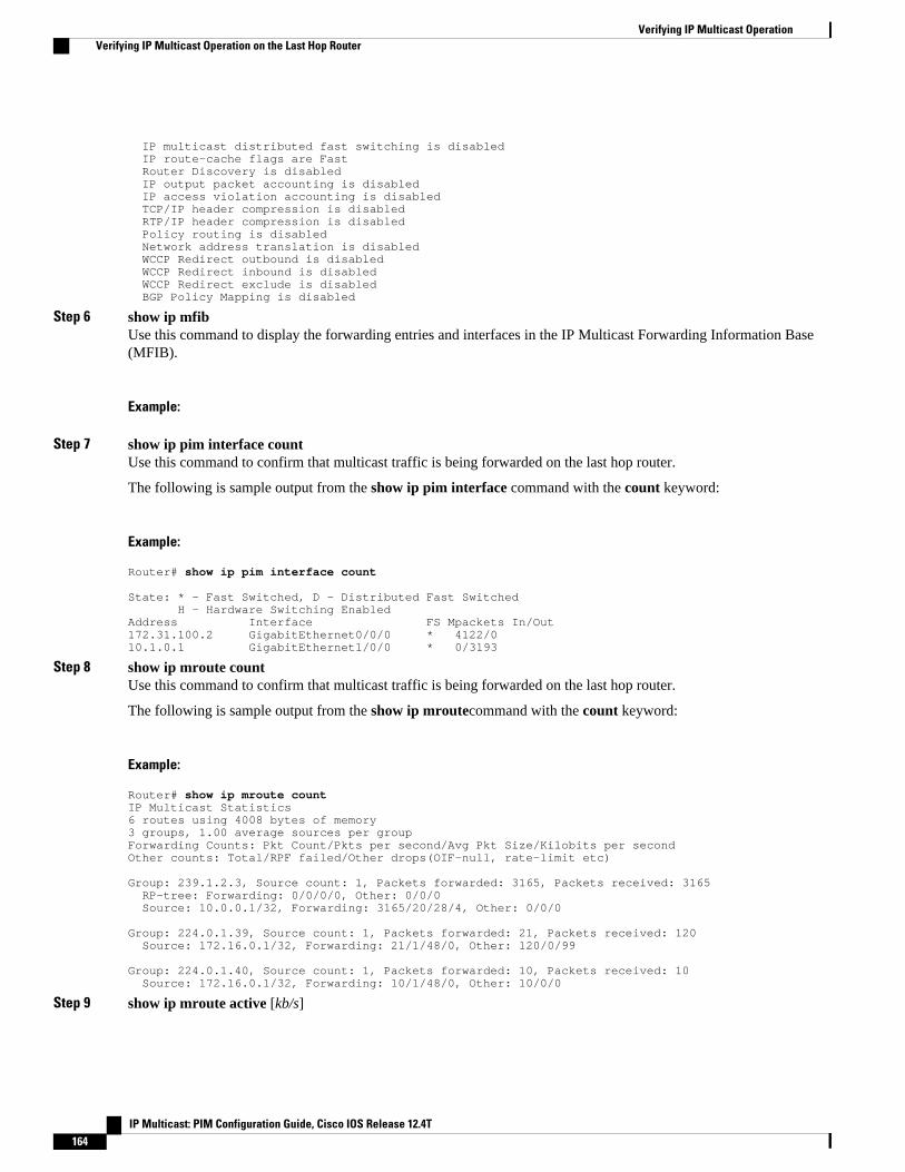
IP multicast distributed fast switching is disabled IP route-cache flags are Fast Router Discovery is disabled IP output packet accounting is disabled IP access violation accounting is disabled TCP/IP header compression is disabled RTP/IP header compression is disabled Policy routing is disabled Network address translation is disabled WCCP Redirect outbound is disabled WCCP Redirect inbound is disabled WCCP Redirect exclude is disabled BGP Policy Mapping is disabled
Step 6 show ip mfibUse this command to display the forwarding entries and interfaces in the IP Multicast Forwarding Information Base(MFIB).
Example:
Step 7 show ip pim interface countUse this command to confirm that multicast traffic is being forwarded on the last hop router.
The following is sample output from the show ip pim interface command with the count keyword:
Example:
Router# show ip pim interface count State: * - Fast Switched, D - Distributed Fast Switched H - Hardware Switching EnabledAddress Interface FS Mpackets In/Out172.31.100.2 GigabitEthernet0/0/0 * 4122/010.1.0.1 GigabitEthernet1/0/0 * 0/3193
Step 8 show ip mroute countUse this command to confirm that multicast traffic is being forwarded on the last hop router.
The following is sample output from the show ip mroutecommand with the count keyword:
Example:
Router# show ip mroute countIP Multicast Statistics6 routes using 4008 bytes of memory3 groups, 1.00 average sources per groupForwarding Counts: Pkt Count/Pkts per second/Avg Pkt Size/Kilobits per secondOther counts: Total/RPF failed/Other drops(OIF-null, rate-limit etc) Group: 239.1.2.3, Source count: 1, Packets forwarded: 3165, Packets received: 3165 RP-tree: Forwarding: 0/0/0/0, Other: 0/0/0 Source: 10.0.0.1/32, Forwarding: 3165/20/28/4, Other: 0/0/0 Group: 224.0.1.39, Source count: 1, Packets forwarded: 21, Packets received: 120 Source: 172.16.0.1/32, Forwarding: 21/1/48/0, Other: 120/0/99 Group: 224.0.1.40, Source count: 1, Packets forwarded: 10, Packets received: 10 Source: 172.16.0.1/32, Forwarding: 10/1/48/0, Other: 10/0/0
Step 9 show ip mroute active [kb/s]
Verifying IP Multicast Operation Verifying IP Multicast Operation on the Last Hop Router
IP Multicast: PIM Configuration Guide, Cisco IOS Release 12.4T164
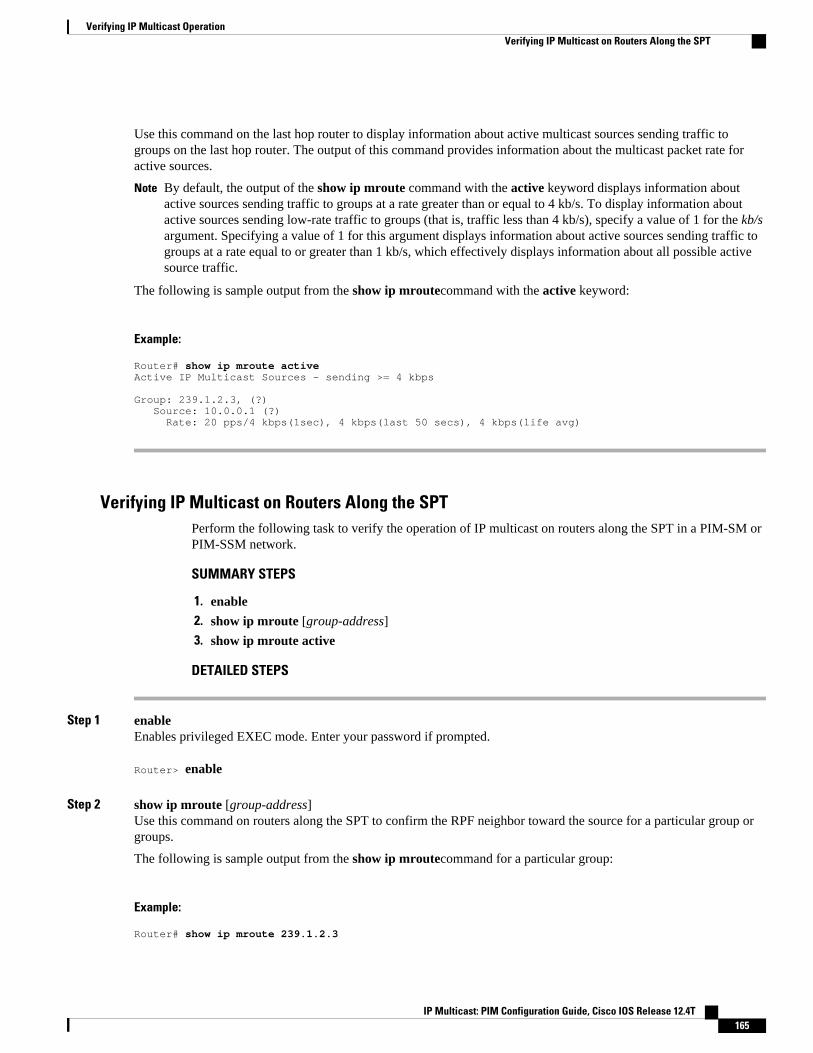
Use this command on the last hop router to display information about active multicast sources sending traffic togroups on the last hop router. The output of this command provides information about the multicast packet rate foractive sources.
Note By default, the output of the show ip mroute command with the active keyword displays information aboutactive sources sending traffic to groups at a rate greater than or equal to 4 kb/s. To display information aboutactive sources sending low-rate traffic to groups (that is, traffic less than 4 kb/s), specify a value of 1 for the kb/sargument. Specifying a value of 1 for this argument displays information about active sources sending traffic togroups at a rate equal to or greater than 1 kb/s, which effectively displays information about all possible activesource traffic.
The following is sample output from the show ip mroutecommand with the active keyword:
Example:
Router# show ip mroute activeActive IP Multicast Sources - sending >= 4 kbps Group: 239.1.2.3, (?) Source: 10.0.0.1 (?) Rate: 20 pps/4 kbps(1sec), 4 kbps(last 50 secs), 4 kbps(life avg)
Verifying IP Multicast on Routers Along the SPTPerform the following task to verify the operation of IP multicast on routers along the SPT in a PIM-SM orPIM-SSM network.
SUMMARY STEPS
1. enable
2. show ip mroute [group-address]
3. show ip mroute active
DETAILED STEPS
Step 1 enableEnables privileged EXEC mode. Enter your password if prompted.
Router> enable
Step 2 show ip mroute [group-address]Use this command on routers along the SPT to confirm the RPF neighbor toward the source for a particular group orgroups.
The following is sample output from the show ip mroutecommand for a particular group:
Example:
Router# show ip mroute 239.1.2.3
Verifying IP Multicast OperationVerifying IP Multicast on Routers Along the SPT
IP Multicast: PIM Configuration Guide, Cisco IOS Release 12.4T 165
(*, 239.1.2.3), 00:17:56/00:03:02, RP 172.16.0.1, flags: S Incoming interface: Null, RPF nbr 0.0.0.0 Outgoing interface list: GigabitEthernet0/0/0, Forward/Sparse-Dense, 00:17:56/00:03:02 (10.0.0.1, 239.1.2.3), 00:15:34/00:03:28, flags: T Incoming interface: Serial1/0, RPF nbr 172.31.200.1 Outgoing interface list: GigabitEthernet0/0/0, Forward/Sparse-Dense, 00:15:34/00:03:02
Step 3 show ip mroute activeUse this command on routers along the SPT to display information about active multicast sources sending to groups.The output of this command provides information about the multicast packet rate for active sources.
Note By default, the output of the show ip mroute command with the active keyword displays information aboutactive sources sending traffic to groups at a rate greater than or equal to 4 kb/s. To display information aboutactive sources sending low-rate traffic to groups (that is, traffic less than 4 kb/s), specify a value of 1 for the kb/sargument. Specifying a value of 1 for this argument displays information about active sources sending traffic togroups at a rate equal to or greater than 1 kb/s, which effectively displays information about all possible activesource traffic.
The following is sample output from the show ip mroute command with the active keyword:
Example:
Router# show ip mroute activeActive IP Multicast Sources - sending >= 4 kbps Group: 239.1.2.3, (?) Source: 10.0.0.1 (?) Rate: 20 pps/4 kbps(1sec), 4 kbps(last 30 secs), 4 kbps(life avg)
Verifying IP Multicast on the First Hop RouterPerform the following task to verify the operation of IP multicast on the first hop router.
SUMMARY STEPS
1. enable
2. show ip mroute [group-address]
3. show ip mroute active [kb/s]
DETAILED STEPS
Step 1 enableEnables privileged EXEC mode.
• Enter your password if prompted.
Verifying IP Multicast Operation Verifying IP Multicast on the First Hop Router
IP Multicast: PIM Configuration Guide, Cisco IOS Release 12.4T166
Router> enable
Step 2 show ip mroute [group-address]Use this command on the first hop router to confirm the F flag has been set for mroutes on the first hop router.
The following is sample output from the show ip mroutefor a particular group:
Example:
Router# show ip mroute 239.1.2.3(*, 239.1.2.3), 00:18:10/stopped, RP 172.16.0.1, flags: SPF Incoming interface: Serial1/0, RPF nbr 172.31.200.2 Outgoing interface list: Null (10.0.0.1, 239.1.2.3), 00:18:10/00:03:22, flags: FT Incoming interface: GigabitEthernet0/0/0, RPF nbr 0.0.0.0 Outgoing interface list: Serial1/0, Forward/Sparse-Dense, 00:18:10/00:03:19
Step 3 show ip mroute active [kb/s]Use this command on the first hop router to display information about active multicast sources sending to groups. Theoutput of this command provides information about the multicast packet rate for active sources.
Note By default, the output of the show ip mroute command with the active keyword displays information aboutactive sources sending traffic to groups at a rate greater than or equal to 4 kb/s. To display information aboutactive sources sending low-rate traffic to groups (that is, traffic less than 4 kb/s), specify a value of 1 for the kb/sargument. Specifying a value of 1 for this argument displays information about active sources sending traffic togroups at a rate equal to or greater than 1 kb/s, which effectively displays information about all possible activesource traffic.
The following is sample output from the show ip mroute command with the active keyword:
Example:
Router# show ip mroute activeActive IP Multicast Sources - sending >= 4 kbps Group: 239.1.2.3, (?) Source: 10.0.0.1 (?) Rate: 20 pps/4 kbps(1sec), 4 kbps(last 30 secs), 4 kbps(life avg)
Configuration Examples for Verifying IP Multicast Operation• Verifying IP Multicast Operation in a PIM-SM or PIM-SSM Network Example, page 168
Verifying IP Multicast OperationConfiguration Examples for Verifying IP Multicast Operation
IP Multicast: PIM Configuration Guide, Cisco IOS Release 12.4T 167
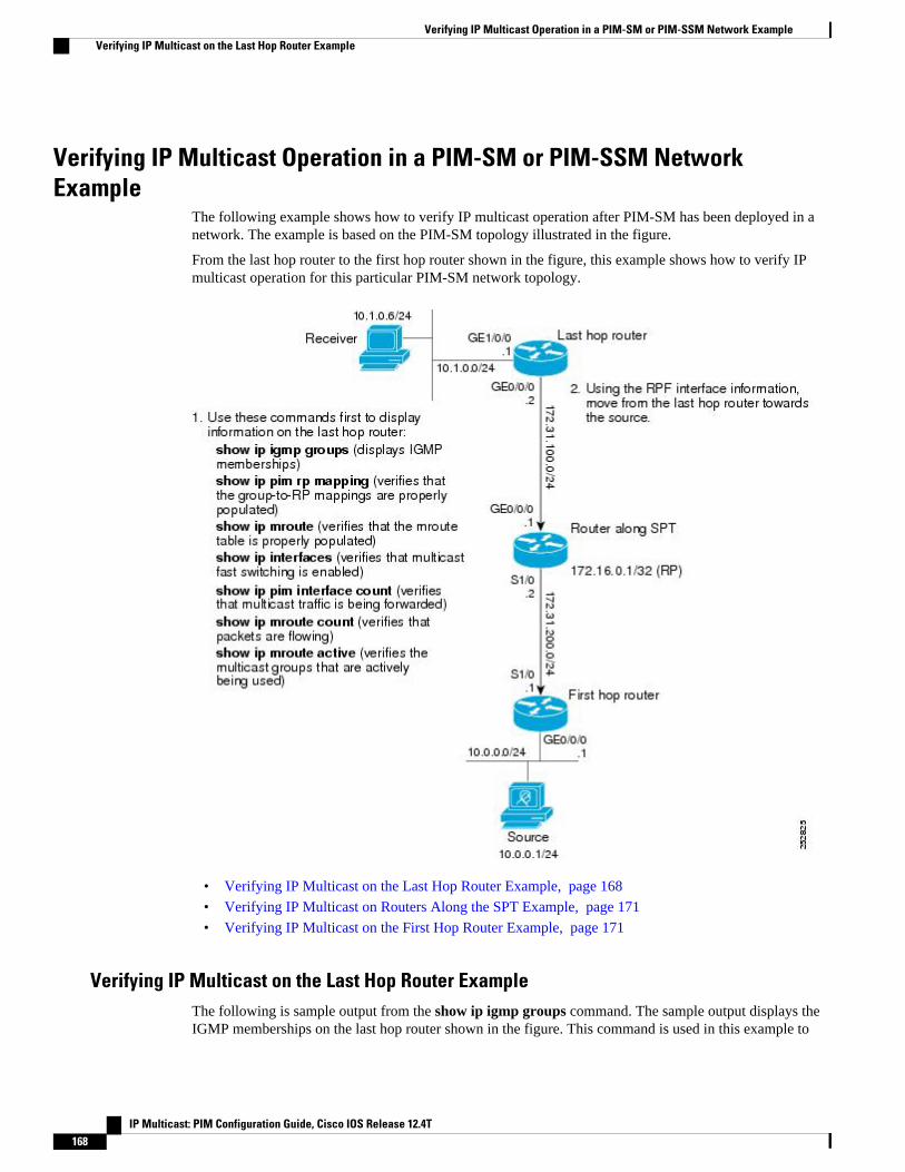
Verifying IP Multicast Operation in a PIM-SM or PIM-SSM NetworkExample
The following example shows how to verify IP multicast operation after PIM-SM has been deployed in anetwork. The example is based on the PIM-SM topology illustrated in the figure.
From the last hop router to the first hop router shown in the figure, this example shows how to verify IPmulticast operation for this particular PIM-SM network topology.
• Verifying IP Multicast on the Last Hop Router Example, page 168
• Verifying IP Multicast on Routers Along the SPT Example, page 171
• Verifying IP Multicast on the First Hop Router Example, page 171
Verifying IP Multicast on the Last Hop Router ExampleThe following is sample output from the show ip igmp groups command. The sample output displays theIGMP memberships on the last hop router shown in the figure. This command is used in this example to
Verifying IP Multicast Operation in a PIM-SM or PIM-SSM Network Example Verifying IP Multicast on the Last Hop Router Example
IP Multicast: PIM Configuration Guide, Cisco IOS Release 12.4T168

confirm that the IGMP cache is being properly populated for the groups that receivers on the LAN havejoined.
Router# show ip igmp groupsIGMP Connected Group MembershipGroup Address Interface Uptime Expires Last Reporter239.1.2.3 GigabitEthernet1/0/0 00:05:14 00:02:14 10.1.0.6224.0.1.39 GigabitEthernet0/0/0 00:09:11 00:02:08 172.31.100.1
The following is sample output from the show ip pim rp mappingcommand. In the sample output, noticethe RP address displayed for the RP field. Use the RP address and group information to verify that thegroup-to-RP mappings have been properly populated on the last hop router shown in the figure.
Note In the output, the “(?)” indicates that the router is unable to resolve an IP address to a hostname.
Router# show ip pim rp mappingPIM Group-to-RP Mappings Group(s) 224.0.0.0/4 RP 172.16.0.1 (?), v2v1 Info source: 172.16.0.1 (?), elected via Auto-RP Uptime: 00:09:11, expires: 00:02:47
The following is sample output from the show ip mroute command. This command is used to verify thatthe mroute table is being properly populated on the last hop router shown in the figure. In the sampleoutput, notice the T flag for the (10.0.0.1, 239.1.2.3) mroute. The T flag indicates that the SPT-bit has beenset, which means a multicast packet was received on the SPT tree for this particular mroute. In addition, theRPF nbr field should point toward the RPF neighbor with the highest IP address determined by unicastrouting toward the multicast source.
Router# show ip mroute(*, 239.1.2.3), 00:05:14/00:03:04, RP 172.16.0.1, flags: SJC Incoming interface: GigabitEthernet0/0/0, RPF nbr 172.31.100.1 Outgoing interface list: Ethernet1/0, Forward/Sparse-Dense, 00:05:10/00:03:04 (10.0.0.1, 239.1.2.3), 00:02:49/00:03:29, flags: T Incoming interface: GigabitEthernet0/0/0, RPF nbr 172.31.100.1 Outgoing interface list: Ethernet1/0, Forward/Sparse-Dense, 00:02:49/00:03:04 (*, 224.0.1.39), 00:10:05/stopped, RP 0.0.0.0, flags: DC Incoming interface: Null, RPF nbr 0.0.0.0 Outgoing interface list: Ethernet1/0, Forward/Sparse-Dense, 00:05:15/00:00:00 Ethernet0/0, Forward/Sparse-Dense, 00:10:05/00:00:00
The following is sample output from the show ip interface command for the incoming interface. Thiscommand is used in this example to confirm that IP multicast fast switching is enabled on the last hoprouter shown in the figure. When IP multicast fast switching is enabled, the line “IP multicast fastswitching is enabled” displays in the output.
Router# show ip interface GigabitEthernet 0/0/0GigabitEthernet0/0/0 is up, line protocol is up Internet address is 172.31.100.2/24 Broadcast address is 255.255.255.255 Address determined by setup command MTU is 1500 bytes Helper address is not set Directed broadcast forwarding is disabled Multicast reserved groups joined: 224.0.0.1 224.0.0.22 224.0.0.13 224.0.0.5 224.0.0.6 Outgoing access list is not set
Verifying IP Multicast OperationVerifying IP Multicast on the Last Hop Router Example
IP Multicast: PIM Configuration Guide, Cisco IOS Release 12.4T 169

Inbound access list is not set Proxy ARP is enabled Local Proxy ARP is disabled Security level is default Split horizon is enabled ICMP redirects are always sent ICMP unreachables are always sent ICMP mask replies are never sent IP fast switching is enabled IP fast switching on the same interface is disabled IP Flow switching is disabled IP CEF switching is disabled IP Fast switching turbo vector IP multicast fast switching is enabled IP multicast distributed fast switching is disabled IP route-cache flags are Fast Router Discovery is disabled IP output packet accounting is disabled IP access violation accounting is disabled TCP/IP header compression is disabled RTP/IP header compression is disabled Policy routing is disabled Network address translation is disabled WCCP Redirect outbound is disabled WCCP Redirect inbound is disabled WCCP Redirect exclude is disabled BGP Policy Mapping is disabled
The following is sample output from the show ip pim interface count command. This command is used inthis example to confirm that multicast traffic is being forwarded to the last hop router shown in the figure.In the sample output, notice the Mpackets In/Out field. This field displays the number of multicast packetsreceived by and sent on each interface listed in the output.
Router# show ip pim interface count State: * - Fast Switched, D - Distributed Fast Switched H - Hardware Switching EnabledAddress Interface FS Mpackets In/Out172.31.100.2 GigabitEthernet0/0/0 * 4122/010.1.0.1 GigabitEthernet1/0/0 * 0/3193
The following is sample output from the show ip mroutecommand with the count keyword. Thiscommand is used on the last hop router shown in the figure to verify the packets being sent to groups fromactive sources. In the sample output, notice the packet count displayed for the Forwarding field. This fielddisplays the packet forwarding count for sources sending to groups.
Router# show ip mroute countIP Multicast Statistics6 routes using 4008 bytes of memory3 groups, 1.00 average sources per groupForwarding Counts: Pkt Count/Pkts per second/Avg Pkt Size/Kilobits per secondOther counts: Total/RPF failed/Other drops(OIF-null, rate-limit etc) Group: 239.1.2.3, Source count: 1, Packets forwarded: 3165, Packets received: 3165 RP-tree: Forwarding: 0/0/0/0, Other: 0/0/0 Source: 10.0.0.1/32, Forwarding: 3165/20/28/4, Other: 0/0/0 Group: 224.0.1.39, Source count: 1, Packets forwarded: 21, Packets received: 120 Source: 172.16.0.1/32, Forwarding: 21/1/48/0, Other: 120/0/99 Group: 224.0.1.40, Source count: 1, Packets forwarded: 10, Packets received: 10 Source: 172.16.0.1/32, Forwarding: 10/1/48/0, Other: 10/0/0
The following is sample output from the show ip mroutecommand with the active keyword. Thiscommand is used on the last hop router shown in the figure to confirm the multicast groups with activesources on the last hop router.
Verifying IP Multicast Operation Verifying IP Multicast on the Last Hop Router Example
IP Multicast: PIM Configuration Guide, Cisco IOS Release 12.4T170
Note In the output, the “(?)” indicates that the router is unable to resolve an IP address to a hostname.
Router# show ip mroute activeActive IP Multicast Sources - sending >= 4 kbps Group: 239.1.2.3, (?) Source: 10.0.0.1 (?) Rate: 20 pps/4 kbps(1sec), 4 kbps(last 50 secs), 4 kbps(life avg)
Verifying IP Multicast on Routers Along the SPT ExampleThe following is sample output from the show ip mroutefor a particular group. This command is used inthis example to verify that the RPF neighbor toward the source is the expected RPF neighbor for the routeralong the SPT shown in the figure.
Router# show ip mroute 239.1.2.3(*, 239.1.2.3), 00:17:56/00:03:02, RP 172.16.0.1, flags: S Incoming interface: Null, RPF nbr 0.0.0.0 Outgoing interface list: Ethernet0/0, Forward/Sparse-Dense, 00:17:56/00:03:02 (10.0.0.1, 239.1.2.3), 00:15:34/00:03:28, flags: T Incoming interface: Serial1/0, RPF nbr 172.31.200.1 Outgoing interface list:
Ethernet0/0, Forward/Sparse-Dense, 00:15:34/00:03:02
The following is sample output from the show ip mroute command with the active keyword from therouter along the SPT shown in the figure. This command is used to confirm the multicast groups withactive sources on this router.
Note In the output, the “(?)” indicates that the router is unable to resolve an IP address to a hostname.
Router# show ip mroute activeActive IP Multicast Sources - sending >= 4 kbps Group: 239.1.2.3, (?) Source: 10.0.0.1 (?) Rate: 20 pps/4 kbps(1sec), 4 kbps(last 30 secs), 4 kbps(life avg)
Verifying IP Multicast on the First Hop Router ExampleThe following is sample output from the show ip mroutefor a particular group. This command is used inthis example to verify the packets being sent to groups from active sources on the first hop router shown inthe figure. In the sample output, notice the packet count displayed for the Forwarding field. This fielddisplays the packet forwarding count for sources sending to groups on the first hop router.
Note The RPF nbr 0.0.0.0 field indicates that the source of an mroute has been reached.
Router# show ip mroute 239.1.2.3(*, 239.1.2.3), 00:18:10/stopped, RP 172.16.0.1, flags: SPF Incoming interface: Serial1/0, RPF nbr 172.31.200.2 Outgoing interface list: Null
Verifying IP Multicast OperationVerifying IP Multicast on Routers Along the SPT Example
IP Multicast: PIM Configuration Guide, Cisco IOS Release 12.4T 171
(10.0.0.1, 239.1.2.3), 00:18:10/00:03:22, flags: FT Incoming interface: GigabitEthernet0/0/0, RPF nbr 0.0.0.0 Outgoing interface list: Serial1/0/0, Forward/Sparse-Dense, 00:18:10/00:03:19
The following is sample output from the show ip mroute command with the active keyword from the firsthop router shown in the figure:
Note In the output, the “(?)” indicates that the router is unable to resolve an IP address to a host name.
Router# show ip mroute activeActive IP Multicast Sources - sending >= 4 kbps Group: 239.1.2.3, (?) Source: 10.0.0.1 (?) Rate: 20 pps/4 kbps(1sec), 4 kbps(last 30 secs), 4 kbps(life avg)
Additional ReferencesRelated Documents
Related Topic Document Title
Overview of the IP multicast technology area “ IP Multicast Technology Overview ” module
PIM-SM and SSM concepts and configurationexamples
“ Configuring Basic IP Multicast ” module
IP multicast commands: complete command syntax,command mode, command history, defaults, usageguidelines, and examples
Cisco IOS IP Multicast Command Reference
Standards
Standard Title
No new or modified standards are supported, andsupport for existing standards has not beenmodified.
--
MIBs
MIB MIBs Link
No new or modified MIBs are supported, andsupport for existing MIBs has not been modified.
To locate and download MIBs for selectedplatforms, Cisco IOS releases, and feature sets, useCisco MIB Locator found at the following URL:
http://www.cisco.com/go/mibs
Verifying IP Multicast Operation Additional References
IP Multicast: PIM Configuration Guide, Cisco IOS Release 12.4T172
RFCs
RFC Title
No new or modified RFCs are supported, andsupport for existing RFCs has not been modified.
--
Technical Assistance
Description Link
The Cisco Support website provides extensiveonline resources, including documentation and toolsfor troubleshooting and resolving technical issueswith Cisco products and technologies.
To receive security and technical information aboutyour products, you can subscribe to variousservices, such as the Product Alert Tool (accessedfrom Field Notices), the Cisco Technical ServicesNewsletter, and Really Simple Syndication (RSS)Feeds.
Access to most tools on the Cisco Support websiterequires a Cisco.com user ID and password.
http://www.cisco.com/techsupport
Feature Information for Verifying IP Multicast OperationThe following table provides release information about the feature or features described in this module.This table lists only the software release that introduced support for a given feature in a given softwarerelease train. Unless noted otherwise, subsequent releases of that software release train also support thatfeature.
Use Cisco Feature Navigator to find information about platform support and Cisco software image support.To access Cisco Feature Navigator, go to www.cisco.com/go/cfn. An account on Cisco.com is not required.
Table 10 Feature Information for Verifying IP Multicast Operation
Feature Name Releases Feature Information
This table is intentionally leftblank because no features wereintroduced or modified in thismodule since Cisco IOS Release12.2(1). This table will beupdated when feature informationis added to this module.
-- --
Verifying IP Multicast OperationFeature Information for Verifying IP Multicast Operation
IP Multicast: PIM Configuration Guide, Cisco IOS Release 12.4T 173

Cisco and the Cisco logo are trademarks or registered trademarks of Cisco and/or its affiliates in the U.S.and other countries. To view a list of Cisco trademarks, go to this URL: www.cisco.com/go/trademarks.Third-party trademarks mentioned are the property of their respective owners. The use of the word partnerdoes not imply a partnership relationship between Cisco and any other company. (1110R)
Any Internet Protocol (IP) addresses and phone numbers used in this document are not intended to beactual addresses and phone numbers. Any examples, command display output, network topology diagrams,and other figures included in the document are shown for illustrative purposes only. Any use of actual IPaddresses or phone numbers in illustrative content is unintentional and coincidental.
Verifying IP Multicast Operation
IP Multicast: PIM Configuration Guide, Cisco IOS Release 12.4T174
SNMP Traps for IP Multicast
The SNMP Traps for IP Multicast feature provides support for the CISCO-PIM-MIB, which is anextension of RFC 2934 and an enhancement to the former Cisco implementation of the PIM MIB.
• Finding Feature Information, page 175• Prerequisites for SNMP Traps for IP Multicast, page 175• Restrictions for SNMP Traps for IP Multicast, page 175• Information About SNMP Traps for IP Multicast, page 176• How to Configure SNMP Traps for IP Multicast, page 176• Configuration Examples for SNMP Traps for IP Multicast, page 178• Additional References, page 178• Feature Information for SNMP Traps for IP Multicast, page 179
Finding Feature InformationYour software release may not support all the features documented in this module. For the latest featureinformation and caveats, see the release notes for your platform and software release. To find informationabout the features documented in this module, and to see a list of the releases in which each feature issupported, see the Feature Information Table at the end of this document.
Use Cisco Feature Navigator to find information about platform support and Cisco software image support.To access Cisco Feature Navigator, go to www.cisco.com/go/cfn. An account on Cisco.com is not required.
Prerequisites for SNMP Traps for IP Multicast• Before performing the tasks in this module, you should be familiar with the concepts explained in the
“ IP Multicast Technology Overview ” module.• This module assumes that IP multicast has been enabled and that the Protocol Independent Multicast
(PIM) interfaces have been configured using the tasks described in the “ Configuring Basic IPMulticast ” module.
• This module assumes that you are familiar with Simple Network Management Protocol (SNMP). Foremore information, see the “ Configuring SNMP Support ” module.
Restrictions for SNMP Traps for IP MulticastThe following MIB tables are not supported in Cisco IOS and Cisco IOS XE software:
IP Multicast: PIM Configuration Guide, Cisco IOS Release 12.4T 175
• pimIpMRouteTable• pimIpMRouteNextHopTable• The pimInterfaceVersion object was removed from RFC 2934 and, therefore, is no longer supported in
software.
Information About SNMP Traps for IP Multicast• PIM MIB Extensions for SNMP Traps for IP Multicast, page 176• Benefits of PIM MIB Extensions, page 176
PIM MIB Extensions for SNMP Traps for IP MulticastProtocol Independent Multicast (PIM) is an IP multicast routing protocol used for routing multicast datapackets to multicast groups. RFC 2934 defines the PIM MIB for IPv4, which describes managed objectsthat enable users to remotely monitor and configure PIM using Simple Network Management Protocol(SNMP).
PIM MIB extensions introduce the following new classes of PIM notifications:
• neighbor-change--This notification results from the following conditions:
◦ A router’s PIM interface is disabled or enabled (using the ip pim command in interfaceconfiguration mode)
◦ A router's PIM neighbor adjacency expires (defined in RFC 2934)• rp-mapping-change--This notification results from a change in the rendezvous point (RP) mapping
information due to either Auto-RP messages or bootstrap router (BSR) messages.• invalid-pim-message--This notification results from the following conditions:
◦ An invalid (*, G) Join or Prune message is received by the device (for example, when a routerreceives a Join or Prune message for which the RP specified in the packet is not the RP for themulticast group)
◦ An invalid PIM register message is received by the device (for example, when a router receives aregister message from a multicast group for which it is not the RP)
Benefits of PIM MIB ExtensionsPIM MIB extensions:
• Allow users to identify changes in the multicast topology of their network by detecting changes in theRP mapping.
• Provide traps to monitor the PIM protocol on PIM-enabled interfaces.• Help users identify routing issues when multicast neighbor adjacencies expire on a multicast interface.• Enable users to monitor RP configuration errors (for example, errors due to flapping in dynamic RP
allocation protocols like Auto-RP).
How to Configure SNMP Traps for IP Multicast• Enabling PIM MIB Extensions for IP Multicast, page 177
PIM MIB Extensions for SNMP Traps for IP Multicast Information About SNMP Traps for IP Multicast
IP Multicast: PIM Configuration Guide, Cisco IOS Release 12.4T176
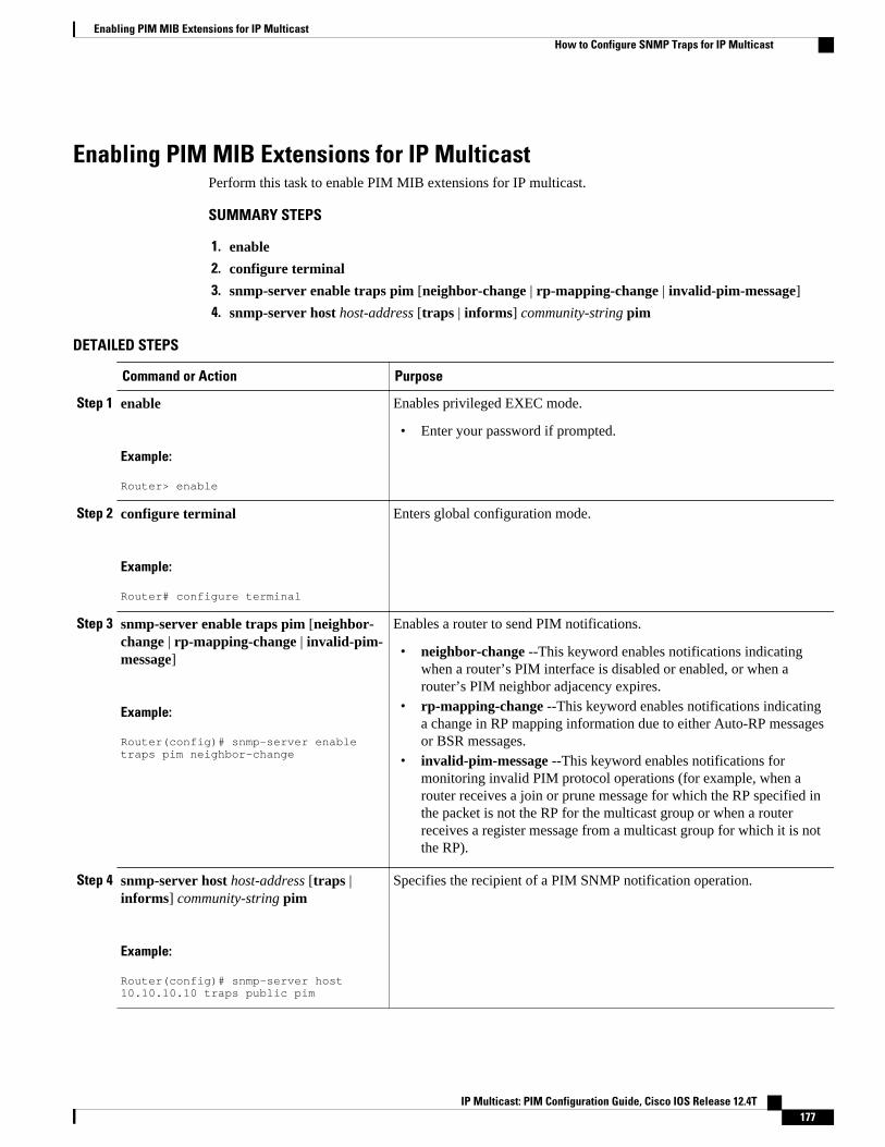
Enabling PIM MIB Extensions for IP MulticastPerform this task to enable PIM MIB extensions for IP multicast.
SUMMARY STEPS
1. enable
2. configure terminal
3. snmp-server enable traps pim [neighbor-change | rp-mapping-change | invalid-pim-message]
4. snmp-server host host-address [traps | informs] community-string pim
DETAILED STEPS
Command or Action Purpose
Step 1 enable
Example:
Router> enable
Enables privileged EXEC mode.
• Enter your password if prompted.
Step 2 configure terminal
Example:
Router# configure terminal
Enters global configuration mode.
Step 3 snmp-server enable traps pim [neighbor-change | rp-mapping-change | invalid-pim-message]
Example:
Router(config)# snmp-server enable traps pim neighbor-change
Enables a router to send PIM notifications.
• neighbor-change --This keyword enables notifications indicatingwhen a router’s PIM interface is disabled or enabled, or when arouter’s PIM neighbor adjacency expires.
• rp-mapping-change --This keyword enables notifications indicatinga change in RP mapping information due to either Auto-RP messagesor BSR messages.
• invalid-pim-message --This keyword enables notifications formonitoring invalid PIM protocol operations (for example, when arouter receives a join or prune message for which the RP specified inthe packet is not the RP for the multicast group or when a routerreceives a register message from a multicast group for which it is notthe RP).
Step 4 snmp-server host host-address [traps |informs] community-string pim
Example:
Router(config)# snmp-server host 10.10.10.10 traps public pim
Specifies the recipient of a PIM SNMP notification operation.
Enabling PIM MIB Extensions for IP MulticastHow to Configure SNMP Traps for IP Multicast
IP Multicast: PIM Configuration Guide, Cisco IOS Release 12.4T 177
Configuration Examples for SNMP Traps for IP Multicast• Example Enabling PIM MIB Extensions for IP Multicast, page 178
Example Enabling PIM MIB Extensions for IP MulticastThe following example shows how to configure a router to generate notifications indicating that a PIMinterface of the router has been enabled. The first line configures PIM traps to be sent as SNMP v2c traps tothe host with IP address 10.0.0.1. The second line configures the router to send the neighbor-change classof trap notification to the host.
snmp-server host 10.0.0.1 traps version 2c public pim snmp-server enable traps pim neighbor-change interface ethernet0/0 ip pim sparse-dense-mode
Additional ReferencesRelated Documents
Related Topic Document Title
Cisco IOS commands Cisco IOS Master Commands List, All Releases
IP multicast commands Cisco IOS IP Multicast Command Reference
Standards
Standard Title
No new or modified standards are supported, andsupport for existing standards has not beenmodified.
--
MIBs
MIB MIBs Link
CISCO-PIM-MIB To locate and download MIBs for selectedplatforms, Cisco software releases, and feature sets,use Cisco MIB Locator found at the followingURL:
http://www.cisco.com/go/mibs
Example Enabling PIM MIB Extensions for IP Multicast Configuration Examples for SNMP Traps for IP Multicast
IP Multicast: PIM Configuration Guide, Cisco IOS Release 12.4T178
RFCs
RFC Title
RFC 2934 Protocol Independent Multicast MIB for IPv4
Technical Assistance
Description Link
The Cisco Support and Documentation websiteprovides online resources to downloaddocumentation, software, and tools. Use theseresources to install and configure the software andto troubleshoot and resolve technical issues withCisco products and technologies. Access to mosttools on the Cisco Support and Documentationwebsite requires a Cisco.com user ID andpassword.
http://www.cisco.com/cisco/web/support/index.html
Feature Information for SNMP Traps for IP MulticastThe following table provides release information about the feature or features described in this module.This table lists only the software release that introduced support for a given feature in a given softwarerelease train. Unless noted otherwise, subsequent releases of that software release train also support thatfeature.
Use Cisco Feature Navigator to find information about platform support and Cisco software image support.To access Cisco Feature Navigator, go to www.cisco.com/go/cfn. An account on Cisco.com is not required.
Table 11 Feature Information for SNMP Traps for IP Multicast
Feature Name Releases Feature Information
SNMP Traps for IP Multicast 12.0(15)S
12.2(4)T
Cisco IOS XE 3.1.0SG
12.2(50)SY
The SNMP Traps for IP Multicastfeature provides support for theCISCO-PIM-MIB, which is anextension of RFC 2934 and anenhancement to the former Ciscoimplementation of the PIM MIB.
The following commands wereintroduced or modified: snmp-server enable traps pim, snmp-server host.
Cisco and the Cisco logo are trademarks or registered trademarks of Cisco and/or its affiliates in the U.S.and other countries. To view a list of Cisco trademarks, go to this URL: www.cisco.com/go/trademarks.
SNMP Traps for IP MulticastFeature Information for SNMP Traps for IP Multicast
IP Multicast: PIM Configuration Guide, Cisco IOS Release 12.4T 179

Third-party trademarks mentioned are the property of their respective owners. The use of the word partnerdoes not imply a partnership relationship between Cisco and any other company. (1110R)
Any Internet Protocol (IP) addresses and phone numbers used in this document are not intended to beactual addresses and phone numbers. Any examples, command display output, network topology diagrams,and other figures included in the document are shown for illustrative purposes only. Any use of actual IPaddresses or phone numbers in illustrative content is unintentional and coincidental.
SNMP Traps for IP Multicast
IP Multicast: PIM Configuration Guide, Cisco IOS Release 12.4T180
Monitoring and Maintaining IP Multicast
This module describes many ways to monitor and maintain an IP multicast network, such as
• displaying which neighboring multicast routers are peering with the local router• displaying multicast packet rates and loss information• tracing the path from a source to a destination branch for a multicast distribution tree• displaying the contents of the IP multicast routing table, information about interfaces configured for
PIM, the PIM neighbors discovered by the router, and contents of the IP fast-switching cache• clearing caches, tables, and databases• monitoring the delivery of IP multicast packets and being alerted if the delivery fails to meet certain
parameters (IP multicast heartbeat)• using session description and announcement protocols and applications to assist the advertisement of
multicast multimedia conferences and other multicast sessions and communicating the relevantsession setup information to prospective participants (SAP listener support)
• storing IP multicast packet headers in a cache and displaying them to find out information such aswho is sending IP multicast packets to what groups and any multicast forwarding loops in yournetwork
• disabling fast switching of IP multicast in order to log debug messages
• Finding Feature Information, page 181• Prerequisites for Monitoring and Maintaining IP Multicast, page 181• Information About Monitoring and Maintaining IP Multicast, page 182• How to Monitor and Maintain IP Multicast, page 183• Configuration Examples for Monitoring and Maintaining IP Multicast, page 193• Additional References, page 197
Finding Feature InformationYour software release may not support all the features documented in this module. For the latest featureinformation and caveats, see the release notes for your platform and software release. To find informationabout the features documented in this module, and to see a list of the releases in which each feature issupported, see the Feature Information Table at the end of this document.
Use Cisco Feature Navigator to find information about platform support and Cisco software image support.To access Cisco Feature Navigator, go to www.cisco.com/go/cfn. An account on Cisco.com is not required.
Prerequisites for Monitoring and Maintaining IP Multicast
IP Multicast: PIM Configuration Guide, Cisco IOS Release 12.4T 181
• Before performing the tasks in this module, you should be familiar with the concepts described in the“IP Multicast Technology Overview” module.
• You must also have enabled IP multicast and have Protocol Independent Multicast (PIM) configuredand running on your network. Refer to the “Configuring Basic IP Multicast” module.
Information About Monitoring and Maintaining IP Multicast• IP Multicast Delivery Using IP Multicast Heartbeat, page 182• Session Announcement Protocol (SAP), page 183
IP Multicast Delivery Using IP Multicast HeartbeatThe IP multicast heartbeat feature provides a way to monitor the status of IP multicast delivery and beinformed when the delivery fails (via Simple Network Management Protocol [SNMP] traps).
• IP Multicast Heartbeat, page 182• SNMP Notifications, page 182
IP Multicast HeartbeatThe IP Multicast Heartbeat feature enables you to monitor the delivery of IP multicast packets and to bealerted if the delivery fails to meet certain parameters.
Although you could alternatively use MRM to monitor IP multicast, you can perform the following taskswith IP multicast heartbeat that you cannot perform with MRM:
• Generate an SNMP trap• Monitor a production multicast stream
When IP multicast heartbeat is enabled, the router monitors IP multicast packets destined for a particularmulticast group at a particular interval. If the number of packets observed is less than a configuredminimum amount, the router sends an SNMP trap to a specified network management station to indicate aloss of heartbeat exception.
The ip multicast heartbeat command does not create a heartbeat if there is no existing multicastforwarding state for group in the router. This command will not create a multicast forwarding state in therouter. Use the ip igmp static-groupcommandon the router or on a downstream router to force forwardingof IP multicast traffic. Use the snmp-server host ipmulticast command to enable the sending of IPmulticast traps to specific receiver hosts. Use the debug ip mhbeatcommand to debug the MulticastHeartbeat feature.
SNMP NotificationsA key feature of SNMP is the ability to generate notifications from an SNMP agent. These notifications donot require that requests be sent from the SNMP manager. Unsolicited (asynchronous) notifications can begenerated as traps or inform requests. Traps are messages alerting the SNMP manager to a condition on thenetwork. Inform requests (informs) are traps that include a request for confirmation of receipt from theSNMP manager. Notifications can indicate improper user authentication, restarts, the closing of aconnection, loss of connection to a neighbor router, or other significant events.
Traps are less reliable than informs because the receiver does not send any acknowledgment when itreceives a trap. The sender cannot determine if the trap was received. An SNMP manager that receives an
IP Multicast Delivery Using IP Multicast Heartbeat Information About Monitoring and Maintaining IP Multicast
IP Multicast: PIM Configuration Guide, Cisco IOS Release 12.4T182
inform request acknowledges the message with an SNMP response protocol data unit (PDU). If themanager does not receive an inform request, it does not send a response. If the sender never receives aresponse, the inform request can be sent again. Thus, informs are more likely to reach their intendeddestination.
However, traps are often preferred because informs consume more resources in the router and in thenetwork. Unlike a trap, which is discarded as soon as it is sent, an inform request must be held in memoryuntil a response is received or the request times out. Also, traps are sent only once, while an inform may beretried several times. The retries increase traffic and contribute to a higher overhead on the network. Thus,traps and inform requests provide a trade-off between reliability and resources. If it is important that theSNMP manager receives every notification, use inform requests. However, if you are concerned abouttraffic on your network or memory in the router and you need not receive every notification, use traps.
Session Announcement Protocol (SAP)Session Announcement Protocol (SAP) listener support is needed to use session description andannouncement protocols and applications to assist the advertisement of multicast multimedia conferencesand other multicast sessions and to communicate the relevant session setup information to prospectiveparticipants.
Sessions are described by the Session Description Protocol (SDP), which is defined in RFC 2327. SDPprovides a formatted, textual description of session properties (for example, contact information, sessionlifetime, and the media) being used in the session (for example, audio, video, and whiteboard) with theirspecific attributes such as time-to-live (TTL) scope, group address, and User Datagram Protocol (UDP)port number.
Many multimedia applications rely on SDP for session descriptions. However, they may use differentmethods to disseminate these session descriptions. For example, IP/TV relies on the web to disseminatesession descriptions to participants. In this example, participants must know of a web server that providesthe session information.
MBONE applications (for example, vic, vat, and wb) and other applications rely on multicast sessioninformation sent throughout the network. In these cases, SAP is used to transport the SDP sessionannouncements. SAP Version 2 uses the well-known session directory multicast group 224.2.127.254 todisseminate SDP session descriptions for global scope sessions and group 239.255.255.255 foradministrative scope sessions.
Note The Session Directory (SDR) application is commonly used to send and receive SDP/SAP sessionannouncements.
How to Monitor and Maintain IP Multicast• Displaying Multicast Peers Packet Rates and Loss Information and Tracing a Path, page 184
• Displaying IP Multicast System and Network Statistics, page 185
• Clearing IP Multicast Routing Table or Caches, page 186
• Monitoring IP Multicast Delivery Using IP Multicast Heartbeat, page 188
• Advertising Multicast Multimedia Sessions Using SAP Listener, page 189
• Storing IP Multicast Headers, page 191
• Disabling Fast Switching of IP Multicast, page 192
Session Announcement Protocol (SAP)How to Monitor and Maintain IP Multicast
IP Multicast: PIM Configuration Guide, Cisco IOS Release 12.4T 183
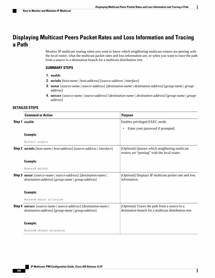
Displaying Multicast Peers Packet Rates and Loss Information and Tracinga Path
Monitor IP multicast routing when you want to know which neighboring multicast routers are peering withthe local router, what the multicast packet rates and loss information are, or when you want to trace the pathfrom a source to a destination branch for a multicast distribution tree.
SUMMARY STEPS
1. enable
2. mrinfo [host-name | host-address] [source-address | interface]
3. mstat {source-name | source-address} [destination-name | destination-address] [group-name | group-address]
4. mtrace {source-name | source-address} [destination-name | destination-address] [group-name | group-address]
DETAILED STEPS
Command or Action Purpose
Step 1 enable
Example:
Router> enable
Enables privileged EXEC mode.
• Enter your password if prompted.
Step 2 mrinfo [host-name | host-address] [source-address | interface]
Example:
Router# mrinfo
(Optional) Queries which neighboring multicastrouters are “peering” with the local router.
Step 3 mstat {source-name | source-address} [destination-name |destination-address] [group-name | group-address]
Example:
Router# mstat allsource
(Optional) Displays IP multicast packet rate and lossinformation.
Step 4 mtrace {source-name | source-address} [destination-name |destination-address] [group-name | group-address]
Example:
Router# mtrace allsource
(Optional) Traces the path from a source to adestination branch for a multicast distribution tree.
Displaying Multicast Peers Packet Rates and Loss Information and Tracing a Path How to Monitor and Maintain IP Multicast
IP Multicast: PIM Configuration Guide, Cisco IOS Release 12.4T184
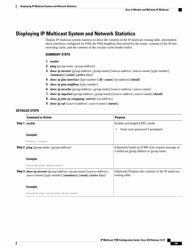
Displaying IP Multicast System and Network StatisticsDisplay IP multicast system statistics to show the contents of the IP multicast routing table, informationabout interfaces configured for PIM, the PIM neighbors discovered by the router, contents of the IP fast-switching cache, and the contents of the circular cache header buffer.
SUMMARY STEPS
1. enable
2. ping [group-name | group-address]
3. show ip mroute [group-address | group-name] [source-address | source-name] [type number][summary] [count] [active kbps]
4. show ip pim interface [type number] [df | count] [rp-address] [detail]
5. show ip pim neighbor [type number]
6. show ip mcache [group-address | group-name] [source-address | source-name]
7. show ip mpacket [group-address | group-name] [source-address | source-name] [detail]
8. show ip pim rp [mapping | metric] [rp-address]
9. show ip rpf {source-address | source-name} [metric]
DETAILED STEPS
Command or Action Purpose
Step 1 enable
Example:
Router> enable
Enables privileged EXEC mode.
• Enter your password if prompted.
Step 2 ping [group-name | group-address]
Example:
Router# ping cbone-audio
(Optional) Sends an ICMP echo request message toa multicast group address or group name.
Step 3 show ip mroute [group-address | group-name] [source-address |source-name] [type number] [summary] [count] [active kbps]
Example:
Router# show ip mroute cbone-audio
(Optional) Displays the contents of the IP multicastrouting table.
Displaying IP Multicast System and Network StatisticsHow to Monitor and Maintain IP Multicast
IP Multicast: PIM Configuration Guide, Cisco IOS Release 12.4T 185
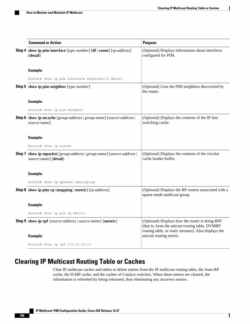
Command or Action Purpose
Step 4 show ip pim interface [type number] [df | count] [rp-address][detail]
Example:
Router# show ip pim interface ethernet1/0 detail
(Optional) Displays information about interfacesconfigured for PIM.
Step 5 show ip pim neighbor [type number]
Example:
Router# show ip pim neighbor
(Optional) Lists the PIM neighbors discovered bythe router.
Step 6 show ip mcache [group-address | group-name] [source-address |source-name]
Example:
Router# show ip mcache
(Optional) Displays the contents of the IP fast-switching cache.
Step 7 show ip mpacket [group-address | group-name] [source-address |source-name] [detail]
Example:
Router# show ip mpacket smallgroup
(Optional) Displays the contents of the circularcache header buffer.
Step 8 show ip pim rp [mapping | metric] [rp-address]
Example:
Router# show ip pim rp metric
(Optional) Displays the RP routers associated with asparse mode multicast group.
Step 9 show ip rpf {source-address | source-name} [metric]
Example:
Router# show ip rpf 172.16.10.13
(Optional) Displays how the router is doing RPF(that is, from the unicast routing table, DVMRProuting table, or static mroutes). Also displays theunicast routing metric.
Clearing IP Multicast Routing Table or CachesClear IP multicast caches and tables to delete entries from the IP multicast routing table, the Auto-RPcache, the IGMP cache, and the caches of Catalyst switches. When these entries are cleared, theinformation is refreshed by being relearned, thus eliminating any incorrect entries.
Clearing IP Multicast Routing Table or Caches How to Monitor and Maintain IP Multicast
IP Multicast: PIM Configuration Guide, Cisco IOS Release 12.4T186
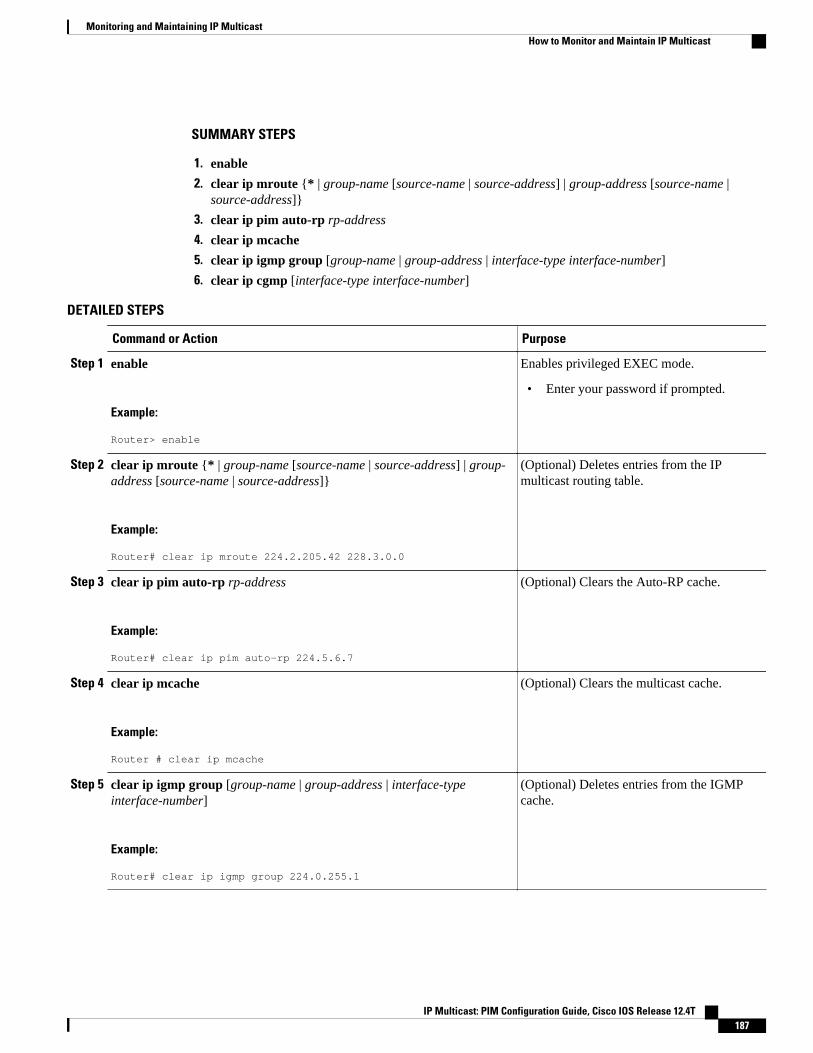
SUMMARY STEPS
1. enable
2. clear ip mroute {* | group-name [source-name | source-address] | group-address [source-name |source-address]}
3. clear ip pim auto-rp rp-address
4. clear ip mcache
5. clear ip igmp group [group-name | group-address | interface-type interface-number]
6. clear ip cgmp [interface-type interface-number]
DETAILED STEPS
Command or Action Purpose
Step 1 enable
Example:
Router> enable
Enables privileged EXEC mode.
• Enter your password if prompted.
Step 2 clear ip mroute {* | group-name [source-name | source-address] | group-address [source-name | source-address]}
Example:
Router# clear ip mroute 224.2.205.42 228.3.0.0
(Optional) Deletes entries from the IPmulticast routing table.
Step 3 clear ip pim auto-rp rp-address
Example:
Router# clear ip pim auto-rp 224.5.6.7
(Optional) Clears the Auto-RP cache.
Step 4 clear ip mcache
Example:
Router # clear ip mcache
(Optional) Clears the multicast cache.
Step 5 clear ip igmp group [group-name | group-address | interface-typeinterface-number]
Example:
Router# clear ip igmp group 224.0.255.1
(Optional) Deletes entries from the IGMPcache.
Monitoring and Maintaining IP MulticastHow to Monitor and Maintain IP Multicast
IP Multicast: PIM Configuration Guide, Cisco IOS Release 12.4T 187

Command or Action Purpose
Step 6 clear ip cgmp [interface-type interface-number]
Example:
Router# clear ip cgmp
(Optional) Clears all group entries from thecaches of Catalyst switches.
Monitoring IP Multicast Delivery Using IP Multicast Heartbeat
SUMMARY STEPS
1. enable
2. configure terminal
3. ip multicast-routing
4. snmp-server host {hostname | ip-address} [traps | informs] [version {1 | 2c | 3 [auth | noauth |priv]}] community-string[udp-port port] [notification-type]
5. snmp-server enable traps ipmulticast
6. ip multicast heartbeat group-address minimum-number window-size interval
DETAILED STEPS
Command or Action Purpose
Step 1 enable
Example:
Router> enable
Enables privileged EXEC mode.
• Enter your password if prompted.
Step 2 configure terminal
Example:
Router# configure terminal
Enters global configuration mode.
Step 3 ip multicast-routing
Example:
Router(config)# ip multicast-routing
Enables IP multicast routing.
Monitoring IP Multicast Delivery Using IP Multicast Heartbeat How to Monitor and Maintain IP Multicast
IP Multicast: PIM Configuration Guide, Cisco IOS Release 12.4T188
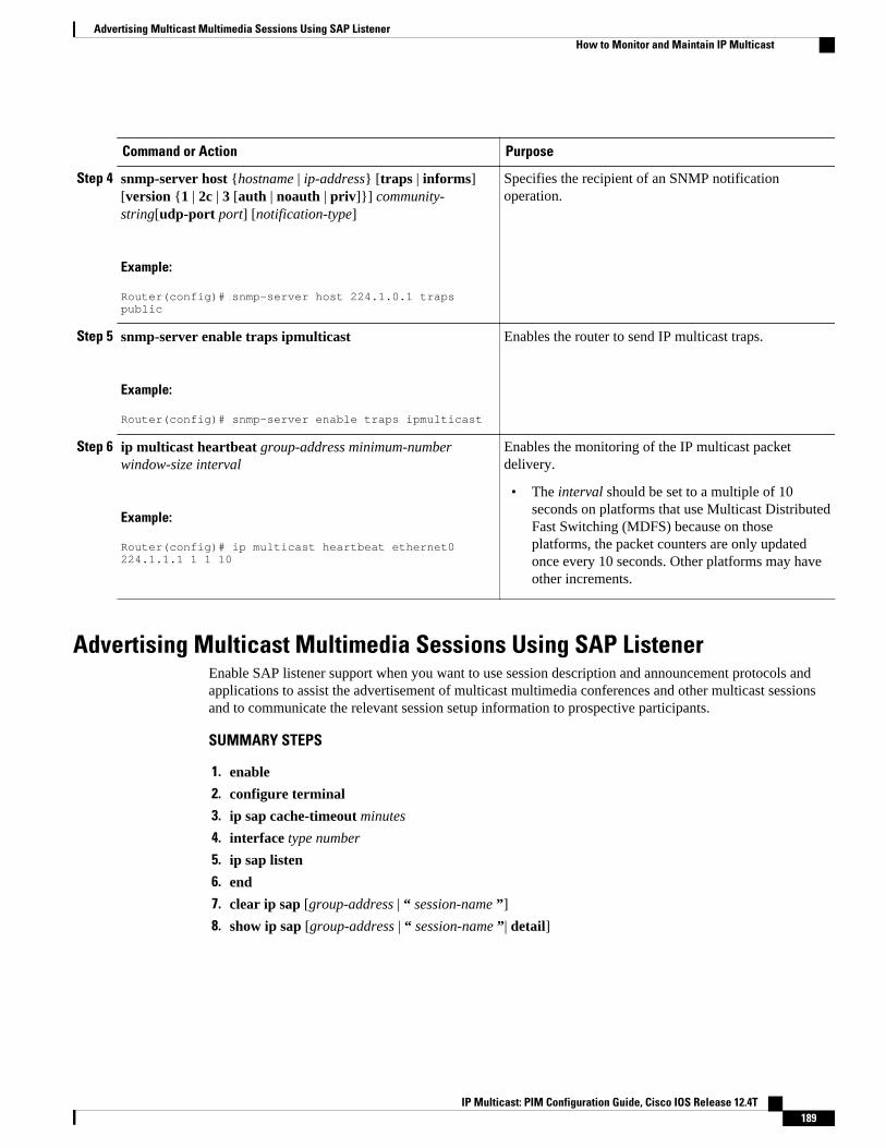
Command or Action Purpose
Step 4 snmp-server host {hostname | ip-address} [traps | informs][version {1 | 2c | 3 [auth | noauth | priv]}] community-string[udp-port port] [notification-type]
Example:
Router(config)# snmp-server host 224.1.0.1 traps public
Specifies the recipient of an SNMP notificationoperation.
Step 5 snmp-server enable traps ipmulticast
Example:
Router(config)# snmp-server enable traps ipmulticast
Enables the router to send IP multicast traps.
Step 6 ip multicast heartbeat group-address minimum-numberwindow-size interval
Example:
Router(config)# ip multicast heartbeat ethernet0 224.1.1.1 1 1 10
Enables the monitoring of the IP multicast packetdelivery.
• The interval should be set to a multiple of 10seconds on platforms that use Multicast DistributedFast Switching (MDFS) because on thoseplatforms, the packet counters are only updatedonce every 10 seconds. Other platforms may haveother increments.
Advertising Multicast Multimedia Sessions Using SAP ListenerEnable SAP listener support when you want to use session description and announcement protocols andapplications to assist the advertisement of multicast multimedia conferences and other multicast sessionsand to communicate the relevant session setup information to prospective participants.
SUMMARY STEPS
1. enable
2. configure terminal
3. ip sap cache-timeout minutes
4. interface type number
5. ip sap listen
6. end
7. clear ip sap [group-address | “ session-name ”]
8. show ip sap [group-address | “ session-name ”| detail]
Advertising Multicast Multimedia Sessions Using SAP ListenerHow to Monitor and Maintain IP Multicast
IP Multicast: PIM Configuration Guide, Cisco IOS Release 12.4T 189
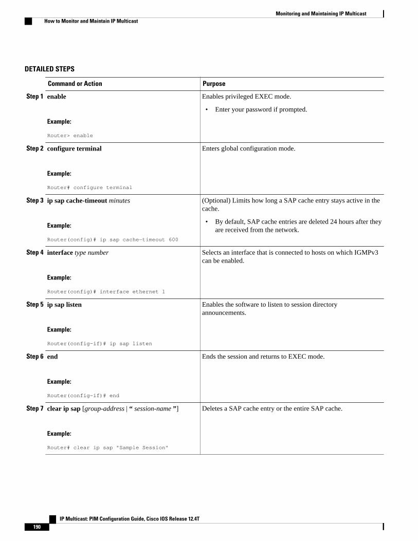
DETAILED STEPS
Command or Action Purpose
Step 1 enable
Example:
Router> enable
Enables privileged EXEC mode.
• Enter your password if prompted.
Step 2 configure terminal
Example:
Router# configure terminal
Enters global configuration mode.
Step 3 ip sap cache-timeout minutes
Example:
Router(config)# ip sap cache-timeout 600
(Optional) Limits how long a SAP cache entry stays active in thecache.
• By default, SAP cache entries are deleted 24 hours after theyare received from the network.
Step 4 interface type number
Example:
Router(config)# interface ethernet 1
Selects an interface that is connected to hosts on which IGMPv3can be enabled.
Step 5 ip sap listen
Example:
Router(config-if)# ip sap listen
Enables the software to listen to session directoryannouncements.
Step 6 end
Example:
Router(config-if)# end
Ends the session and returns to EXEC mode.
Step 7 clear ip sap [group-address | “ session-name ”]
Example:
Router# clear ip sap "Sample Session"
Deletes a SAP cache entry or the entire SAP cache.
Monitoring and Maintaining IP Multicast How to Monitor and Maintain IP Multicast
IP Multicast: PIM Configuration Guide, Cisco IOS Release 12.4T190

Command or Action Purpose
Step 8 show ip sap [group-address | “ session-name ”| detail]
Example:
Router# show ip sap 224.2.197.250 detail
(Optional) Displays the SAP cache.
Storing IP Multicast HeadersYou can store IP multicast packet headers in a cache and then display them to determine any of thefollowing information:
• Who is sending IP multicast packets to what groups• Interpacket delay• Duplicate IP multicast packets (if any)• Multicast forwarding loops in your network (if any)• Scope of the group• UDP port numbers• Packet length
Perform this task if you need any of the information listed above.
SUMMARY STEPS
1. enable
2. configure terminal
3. ip multicast cache-headers [rtp]
4. exit
5. show ip mpacket [group-address | group-name] [source-address | source-name] [detail]
DETAILED STEPS
Command or Action Purpose
Step 1 enable
Example:
Router> enable
Enables privileged EXEC mode.
• Enter your password if prompted.
Step 2 configure terminal
Example:
Router# configure terminal
Enters global configuration mode.
Storing IP Multicast HeadersHow to Monitor and Maintain IP Multicast
IP Multicast: PIM Configuration Guide, Cisco IOS Release 12.4T 191
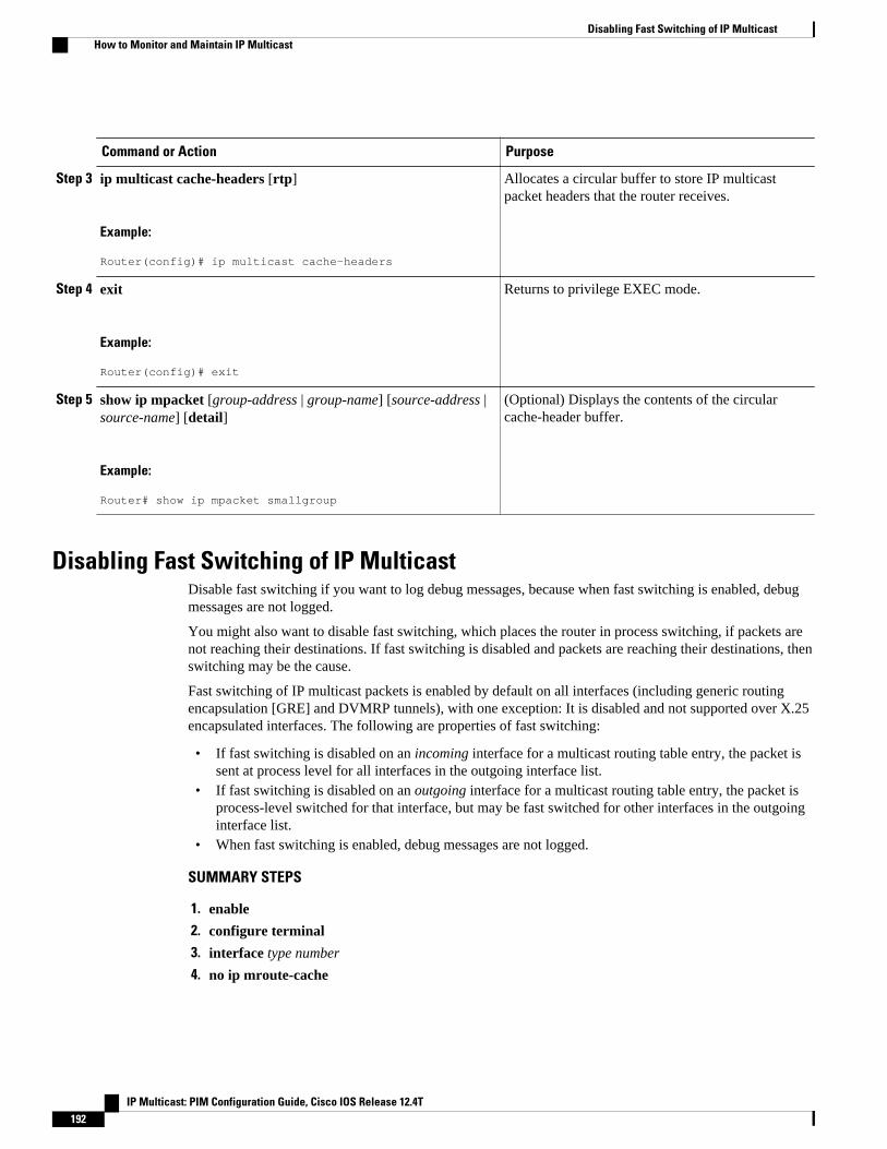
Command or Action Purpose
Step 3 ip multicast cache-headers [rtp]
Example:
Router(config)# ip multicast cache-headers
Allocates a circular buffer to store IP multicastpacket headers that the router receives.
Step 4 exit
Example:
Router(config)# exit
Returns to privilege EXEC mode.
Step 5 show ip mpacket [group-address | group-name] [source-address |source-name] [detail]
Example:
Router# show ip mpacket smallgroup
(Optional) Displays the contents of the circularcache-header buffer.
Disabling Fast Switching of IP MulticastDisable fast switching if you want to log debug messages, because when fast switching is enabled, debugmessages are not logged.
You might also want to disable fast switching, which places the router in process switching, if packets arenot reaching their destinations. If fast switching is disabled and packets are reaching their destinations, thenswitching may be the cause.
Fast switching of IP multicast packets is enabled by default on all interfaces (including generic routingencapsulation [GRE] and DVMRP tunnels), with one exception: It is disabled and not supported over X.25encapsulated interfaces. The following are properties of fast switching:
• If fast switching is disabled on an incoming interface for a multicast routing table entry, the packet issent at process level for all interfaces in the outgoing interface list.
• If fast switching is disabled on an outgoing interface for a multicast routing table entry, the packet isprocess-level switched for that interface, but may be fast switched for other interfaces in the outgoinginterface list.
• When fast switching is enabled, debug messages are not logged.
SUMMARY STEPS
1. enable
2. configure terminal
3. interface type number
4. no ip mroute-cache
Disabling Fast Switching of IP Multicast How to Monitor and Maintain IP Multicast
IP Multicast: PIM Configuration Guide, Cisco IOS Release 12.4T192
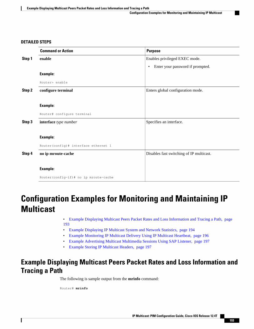
DETAILED STEPS
Command or Action Purpose
Step 1 enable
Example:
Router> enable
Enables privileged EXEC mode.
• Enter your password if prompted.
Step 2 configure terminal
Example:
Router# configure terminal
Enters global configuration mode.
Step 3 interface type number
Example:
Router(config)# interface ethernet 1
Specifies an interface.
Step 4 no ip mroute-cache
Example:
Router(config-if)# no ip mroute-cache
Disables fast switching of IP multicast.
Configuration Examples for Monitoring and Maintaining IPMulticast
• Example Displaying Multicast Peers Packet Rates and Loss Information and Tracing a Path, page193• Example Displaying IP Multicast System and Network Statistics, page 194• Example Monitoring IP Multicast Delivery Using IP Multicast Heartbeat, page 196• Example Advertising Multicast Multimedia Sessions Using SAP Listener, page 197• Example Storing IP Multicast Headers, page 197
Example Displaying Multicast Peers Packet Rates and Loss Information andTracing a Path
The following is sample output from the mrinfo command:
Router# mrinfo
Example Displaying Multicast Peers Packet Rates and Loss Information and Tracing a PathConfiguration Examples for Monitoring and Maintaining IP Multicast
IP Multicast: PIM Configuration Guide, Cisco IOS Release 12.4T 193
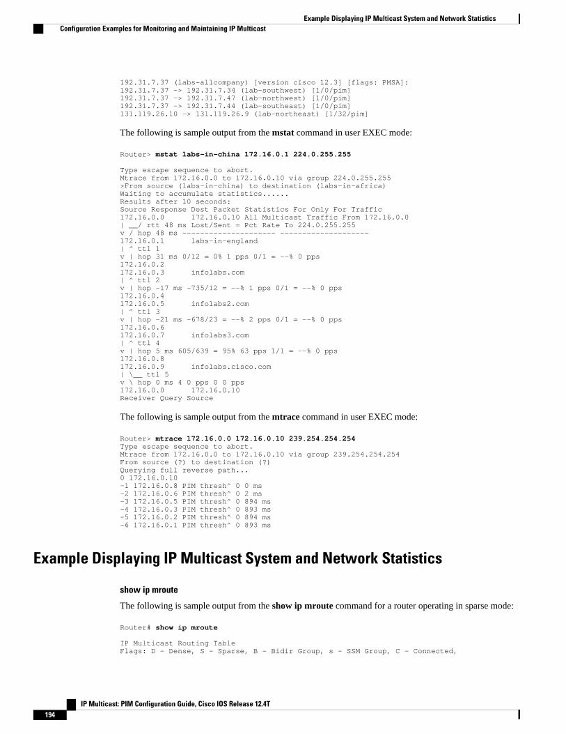
192.31.7.37 (labs-allcompany) [version cisco 12.3] [flags: PMSA]: 192.31.7.37 -> 192.31.7.34 (lab-southwest) [1/0/pim] 192.31.7.37 -> 192.31.7.47 (lab-northwest) [1/0/pim] 192.31.7.37 -> 192.31.7.44 (lab-southeast) [1/0/pim] 131.119.26.10 -> 131.119.26.9 (lab-northeast) [1/32/pim]
The following is sample output from the mstat command in user EXEC mode:
Router> mstat labs-in-china 172.16.0.1 224.0.255.255 Type escape sequence to abort. Mtrace from 172.16.0.0 to 172.16.0.10 via group 224.0.255.255 >From source (labs-in-china) to destination (labs-in-africa) Waiting to accumulate statistics...... Results after 10 seconds: Source Response Dest Packet Statistics For Only For Traffic 172.16.0.0 172.16.0.10 All Multicast Traffic From 172.16.0.0 | __/ rtt 48 ms Lost/Sent = Pct Rate To 224.0.255.255 v / hop 48 ms --------------------- -------------------- 172.16.0.1 labs-in-england | ^ ttl 1 v | hop 31 ms 0/12 = 0% 1 pps 0/1 = --% 0 pps 172.16.0.2 172.16.0.3 infolabs.com| ^ ttl 2 v | hop -17 ms -735/12 = --% 1 pps 0/1 = --% 0 pps 172.16.0.4 172.16.0.5 infolabs2.com | ^ ttl 3 v | hop -21 ms -678/23 = --% 2 pps 0/1 = --% 0 pps 172.16.0.6 172.16.0.7 infolabs3.com | ^ ttl 4 v | hop 5 ms 605/639 = 95% 63 pps 1/1 = --% 0 pps 172.16.0.8 172.16.0.9 infolabs.cisco.com | \__ ttl 5 v \ hop 0 ms 4 0 pps 0 0 pps 172.16.0.0 172.16.0.10 Receiver Query Source
The following is sample output from the mtrace command in user EXEC mode:
Router> mtrace 172.16.0.0 172.16.0.10 239.254.254.254 Type escape sequence to abort. Mtrace from 172.16.0.0 to 172.16.0.10 via group 239.254.254.254 From source (?) to destination (?) Querying full reverse path... 0 172.16.0.10 -1 172.16.0.8 PIM thresh^ 0 0 ms -2 172.16.0.6 PIM thresh^ 0 2 ms -3 172.16.0.5 PIM thresh^ 0 894 ms -4 172.16.0.3 PIM thresh^ 0 893 ms -5 172.16.0.2 PIM thresh^ 0 894 ms -6 172.16.0.1 PIM thresh^ 0 893 ms
Example Displaying IP Multicast System and Network Statistics
show ip mroute
The following is sample output from the show ip mroute command for a router operating in sparse mode:
Router# show ip mroute IP Multicast Routing Table Flags: D - Dense, S - Sparse, B - Bidir Group, s - SSM Group, C - Connected,
Example Displaying IP Multicast System and Network Statistics Configuration Examples for Monitoring and Maintaining IP Multicast
IP Multicast: PIM Configuration Guide, Cisco IOS Release 12.4T194

L - Local, P - Pruned, R - RP-bit set, F - Register flag, T - SPT-bit set, J - Join SPT, M - MSDP created entry, X - Proxy Join Timer Running, A - Candidate for MSDP Advertisement, U - URD, I - Received Source Specific Host Report, Z - Multicast Tunnel, Y - Joined MDT-data group, y - Sending to MDT-data group Timers: Uptime/Expires Interface state: Interface, Next-Hop, State/Mode (*, 224.0.255.3), uptime 5:29:15, RP is 192.168.37.2, flags: SC Incoming interface: Tunnel0, RPF neighbor 10.3.35.1, Dvmrp Outgoing interface list: Ethernet0, Forward/Sparse, 5:29:15/0:02:57 (192.168.46.0/24, 224.0.255.3), uptime 5:29:15, expires 0:02:59, flags: C Incoming interface: Tunnel0, RPF neighbor 10.3.35.1 Outgoing interface list: Ethernet0, Forward/Sparse, 5:29:15/0:02:57
show ip pim interface
The following is sample output from the show ip pim interface command when an interface is specified:
Router# show ip pim interface Ethernet1/0 Address Interface Ver/ Nbr Query DR DR Mode Count Intvl Prior 172.16.1.4 Ethernet1/0 v2/S 1 100 ms 1 172.16.1.4
show ip mcache
The following is sample output from the show ip mcache privileged EXEC command when multicastdistributed switching (MDS) is in effect:
Router# show ip mcache IP Multicast Fast-Switching Cache (*, 239.2.3.4), Fddi3/0/0, Last used: mds Tunnel3 MAC Header: 5000602F9C150000603E473F60AAAA030000000800 (Fddi3/0/0) Tunnel0 MAC Header: 5000602F9C150000603E473F60AAAA030000000800 (Fddi3/0/0) Tunnel1 MAC Header: 5000602F9C150000603E473F60AAAA030000000800 (Fddi3/0/0)
show ip mpacket
The following is sample output from the show ip mpacket command with the group-name argument:
Router# show ip mpacket smallgroup IP Multicast Header Cache - entry count:6, next index: 7 Key: id/ttl timestamp (name) source group D782/117 206416.908 (company1.company.com) 192.168.228.10 224.5.6.7 7302/113 206417.908 (school.edu) 172.16.2.17 224.5.6.7 6CB2/114 206417.412 (company2.company.com) 172.16.19.40 224.5.6.7 D782/117 206417.868 (company1.company.com) 192.168.228.10 224.5.6.7 E2E9/123 206418.488 (company3.com) 239.1.8.10 224.5.6.7 1CA7/127 206418.544 (company4.company.com) 192.168.6.10 224.5.6.7
The following is sample output from the show ip pim rp command:
Router# show ip pim rp Group:227.7.7.7, RP:10.10.0.2, v2, v1, next RP-reachable in 00:00:48
show ip pim rp
The following is sample output from the show ip pim rp command when the mapping keyword isspecified:
Router# show ip pim rp mapping
Monitoring and Maintaining IP MulticastConfiguration Examples for Monitoring and Maintaining IP Multicast
IP Multicast: PIM Configuration Guide, Cisco IOS Release 12.4T 195
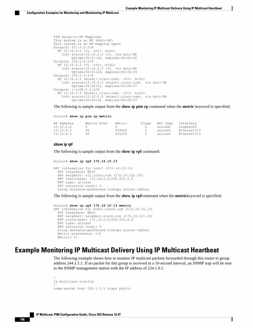
PIM Group-to-RP Mappings This system is an RP (Auto-RP) This system is an RP-mapping agent Group(s) 227.0.0.0/8 RP 10.10.0.2 (?), v2v1, bidir Info source:10.10.0.2 (?), via Auto-RP Uptime:00:01:42, expires:00:00:32Group(s) 228.0.0.0/8 RP 10.10.0.3 (?), v2v1, bidir Info source:10.10.0.3 (?), via Auto-RP Uptime:00:01:26, expires:00:00:34 Group(s) 229.0.0.0/8 RP 10.10.0.5 (mcast1.cisco.com), v2v1, bidir Info source:10.10.0.5 (mcast1.cisco.com), via Auto-RP Uptime:00:00:52, expires:00:00:37 Group(s) (-)230.0.0.0/8 RP 10.10.0.5 (mcast1.cisco.com), v2v1, bidir Info source:10.10.0.5 (mcast1.cisco.com), via Auto-RP Uptime:00:00:52, expires:00:00:37
The following is sample output from the show ip pim rp command when the metric keyword is specified:
Router# show ip pim rp metric RP Address Metric Pref Metric Flags RPF Type Interface 10.10.0.2 0 0 L unicast Loopback0 10.10.0.3 90 409600 L unicast Ethernet3/3 10.10.0.5 90 435200 L unicast Ethernet3/3
show ip rpf
The following is sample output from the show ip rpf command:
Router# show ip rpf 172.16.10.13 RPF information for host1 (172.16.10.13) RPF interface: BRI0 RPF neighbor: sj1.cisco.com (172.16.121.10) RPF route/mask: 172.16.0.0/255.255.0.0 RPF type: unicast RPF recursion count: 0 Doing distance-preferred lookups across tables
The following is sample output from the show ip rpfcommand when the metrickeyword is specified:
Router# show ip rpf 172.16.10.13 metric RPF information for host1.cisco.com (172.16.10.13) RPF interface: BRI0 RPF neighbor: neighbor.cisco.com (172.16.121.10) RPF route/mask: 172.16.0.0/255.255.0.0 RPF type: unicast RPF recursion count: 0 Doing distance-preferred lookups across tables Metric preference: 110 Metric: 11
Example Monitoring IP Multicast Delivery Using IP Multicast HeartbeatThe following example shows how to monitor IP multicast packets forwarded through this router to groupaddress 244.1.1.1. If no packet for this group is received in a 10-second interval, an SNMP trap will be sentto the SNMP management station with the IP address of 224.1.0.1.
! ip multicast-routing ! snmp-server host 224.1.0.1 traps public
Example Monitoring IP Multicast Delivery Using IP Multicast Heartbeat Configuration Examples for Monitoring and Maintaining IP Multicast
IP Multicast: PIM Configuration Guide, Cisco IOS Release 12.4T196
snmp-server enable traps ipmulticast ip multicast heartbeat ethernet0 224.1.1.1 1 1 10
Example Advertising Multicast Multimedia Sessions Using SAP ListenerThe following example enables a router to listen to session directory announcements and changes the SAPcache timeout to 30 minutes.
ip multicast routing ip sap cache-timeout 30 interface loopback 0 ip address 10.0.0.51 255.255.255.0 ip pim sparse-dense mode ip sap listen
The following is sample output from the show ip sap command for a session using multicast group224.2.197.250:
Router# show ip sap 224.2.197.250 SAP Cache - 198 entries Session Name: Session1 Description: This broadcast is brought to you courtesy of Name1. Group: 0.0.0.0, ttl: 0, Contiguous allocation: 1 Lifetime: from 10:00:00 PDT Jul 4 1999 until 10:00:00 PDT Aug 1 1999 Uptime: 4d05h, Last Heard: 00:01:40 Announcement source: 128.102.84.134 Created by: sample 3136541828 3139561476 IN IP4 128.102.84.134 Phone number: Sample Digital Video Lab (555) 555-5555 Email: email1 <[email protected]> URL: http://url.com/ Media: audio 20890 RTP/AVP 0 Media group: 224.2.197.250, ttl: 127 Attribute: ptime:40 Media: video 62806 RTP/AVP 31 Media group: 224.2.190.243, ttl: 127
Example Storing IP Multicast HeadersThe following is sample output from the show ip mpacket command for the group named “smallgroup.”
Router# show ip mpacket smallgroup IP Multicast Header Cache - entry count:6, next index: 7 Key: id/ttl timestamp (name) source group D782/117 206416.908 (company1.company.com) 192.168.228.10 224.5.6.7 7302/113 206417.908 (school.edu) 172.16.2.17 224.5.6.7 6CB2/114 206417.412 (company2.company.com) 172.16.19.40 224.5.6.7 D782/117 206417.868 (company1.company.com) 192.168.228.10 224.5.6.7 E2E9/123 206418.488 (company3.com) 239.1.8.10 224.5.6.7 1CA7/127 206418.544 (company4.company.com) 192.168.6.10 224.5.6.7
Additional ReferencesRelated Documents
Related Topic Document Title
IP multicast SNMP notifications “ Configuring SNMP Support ” module
Example Advertising Multicast Multimedia Sessions Using SAP ListenerAdditional References
IP Multicast: PIM Configuration Guide, Cisco IOS Release 12.4T 197
Related Topic Document Title
IP multicast commands: complete command syntax,command mode, defaults, usage guidelines, andexamples
Cisco IOS IP Multicast Command Reference
MIBs
MIB MIBs Link
• CISCO-IPMROUTE-MIB• MSDP-MIB• IGMP-STD-MIB
To locate and download MIBs for selectedplatforms, Cisco IOS XE releases, and feature sets,use Cisco MIB Locator found at the followingURL:
http://www.cisco.com/go/mibs
RFCs
RFC Title
RFC 2934 Protocol Independent Multicast for IPv4 MIB
Technical Assistance
Description Link
The Cisco Support website provides extensiveonline resources, including documentation and toolsfor troubleshooting and resolving technical issueswith Cisco products and technologies.
To receive security and technical information aboutyour products, you can subscribe to variousservices, such as the Product Alert Tool (accessedfrom Field Notices), the Cisco Technical ServicesNewsletter, and Really Simple Syndication (RSS)Feeds.
Access to most tools on the Cisco Support websiterequires a Cisco.com user ID and password.
http://www.cisco.com/techsupport
Cisco and the Cisco logo are trademarks or registered trademarks of Cisco and/or its affiliates in the U.S.and other countries. To view a list of Cisco trademarks, go to this URL: www.cisco.com/go/trademarks.Third-party trademarks mentioned are the property of their respective owners. The use of the word partnerdoes not imply a partnership relationship between Cisco and any other company. (1110R)
Any Internet Protocol (IP) addresses and phone numbers used in this document are not intended to beactual addresses and phone numbers. Any examples, command display output, network topology diagrams,
Monitoring and Maintaining IP Multicast
IP Multicast: PIM Configuration Guide, Cisco IOS Release 12.4T198

and other figures included in the document are shown for illustrative purposes only. Any use of actual IPaddresses or phone numbers in illustrative content is unintentional and coincidental.
Monitoring and Maintaining IP Multicast
IP Multicast: PIM Configuration Guide, Cisco IOS Release 12.4T 199

Example Storing IP Multicast Headers
IP Multicast: PIM Configuration Guide, Cisco IOS Release 12.4T200