ip power 9258 - opengearftp.opengear.com/download/manual/x-manuals/ip power user...the ip power...
TRANSCRIPT
_____________________________________________________________________________
IP POWER PAGE 1 OF 32
QUICK START amp USER MANUAL
IP Power 9258
Quick Start helliphellip 2 User Manual helliphellip 5 (CD)
Rev 13 November 16 2011
_____________________________________________________________________________
IP POWER PAGE 2 OF 32
Quick Start Guide
1) Check kit contents
Part 508000 IP Power 9258T (USA) or Part 508001 IP Power 9258S (EuropeAustralia) User ManualQuick Start Guide and IP Power CD Power cable
2) Install hardware
Connect power cables For the USA model (NEMA5-15P 100-120V outlets) the individual max output current per outlet is 6A and the total max output current for the 4 outlets is 15A Use a power IN cable with 15A current rating and use power OUT cables with 10A rating for each power outlet
For the EuropeanAustralian model (IEC320-C13 220-250V outlets) the individual max output current per outlet is 6A and the total max output current for the 4 outlets is 10A Use a power IN cable with 10A current rating and use power OUT cable with 10A rating for each power outlet
Connect IP Power NETWORK port to your local 10100 LAN
3) Set IP Power IP address
The IP Powerrsquos default network settings are IP address 192168050 Subnet mask 2552552550
To set a new address either
Connect your PC directly to the IP Powerrsquos Ethernet (NETWORK) port and run IPEditexe You first must copy the IPEditexe program from the IP Power CD on to your PC or
With a PC in the same subnet as the IP Power (ie IP address of 1921680xxx) open the IP Power control web pages as detailed in the next step and select System Setup
_____________________________________________________________________________
IP POWER PAGE 3 OF 32
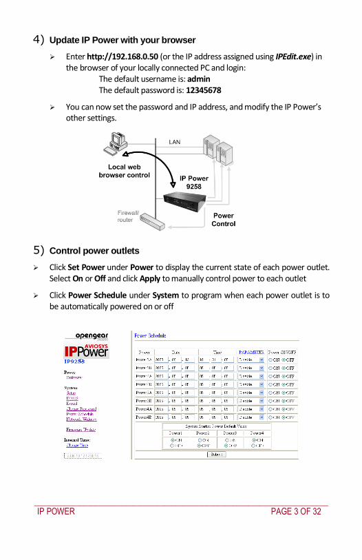
4) Update IP Power with your browser
Enter http192168050 (or the IP address assigned using IPEditexe) in the browser of your locally connected PC and login
The default username is admin The default password is 12345678
You can now set the password and IP address and modify the IP Powerrsquos other settings
5) Control power outlets
Click Set Power under Power to display the current state of each power outlet Select On or Off and click Apply to manually control power to each outlet
Click Power Schedule under System to program when each power outlet is to be automatically powered on or off
_____________________________________________________________________________
IP POWER PAGE 4 OF 32
Publishing history
Date Revision Update details
Feb 2007 11 Covers 138 firmware features
July 2009 12 Added Telnet and SNMP (firmware 152) and serial command line details (firmware 153)
Nov 2011 13 Telnet authentication (firmware 155)
WARNING
Any changes to this equipment without permission may cause damages to your equipment This equipment has been proven by CE amp FCC to be prevented from the influence of harmful electronic jamming in normal business use conditions
IMPORTANT NOTICE
1 We have no responsibility for possible damage caused by improper usage or abnormal working environment
2 Do not use IP POWER in strong vibrating condition 3 Please contact the dealer If IP POWER works improperly
Copyright copy 2009 All rights reserved No part of this publication may be reproduced stored in a retrieval system or transmitted in any form or by any means electronic mechanical photocopying recording or otherwise without the prior written consent of us All other products mentioned in this document are trademarks of their respective manufactures We are exempt to notify any change of our products
_____________________________________________________________________________
IP POWER PAGE 5 OF 32
IP Power 9258 User Manual
Table of Contents
1 Introduction 6
2 Interface Description 6
3 Hardware and Software Installation 7
4 Initial Settings 8
5 IP Power Control Using Browser 11 Setting the password for IP Power 13 Setting the IP Powerrsquos IP address 13 Email settings 15 Power control using the time schedule 16 Default outlet settings 16 Clock settings amp network time protocol (NTP) 17 Wake on LAN (WOL) 17
6 Firmware Update 18
7 DDNS Settings 19
8 Control Using Telnet HTTP amp SNMP Commands 20
9 Frequently Asked Question 27
10 Manual Control Mode 27
11 IP Power Control Using Console Server 28
12 General IP Power Control Using Serial Port 30
_____________________________________________________________________________
IP POWER PAGE 6 OF 32
1 Introduction
The IP power 9258 is a web browser controlled power switch that can be used easily for industrial or commercial power control With the remote network control technology a user connected to the local area network or Internet can query and control the power supply of attached equipment There is no special software required Maximum rated voltage for each of the 4 outlets 250V AC 24V DC Maximum rated current total 15A ACDC (9258T) 10A ACDC (9258S) Maximum rated current per individual outlet 6A ACDC Action delay max 10ms Operating temperature 0 ~ 70degC IP Power model 9258S - for EUAUUK for 220-250V use power (IN) cable at 10A current Max output current 10A (total) 6A (individual)
IP Power model 9258T - for USTWJP for 100-120V use power (IN) cable at 15A current Max output current 15A (total) 6A (individual)
2 Interface Description
IP Power 9258 front interface (from left to right)
RESET Self-protect AC reset button IP Power 9258 can cut off the power supply of outlets automatically if there is a short circuit or current
_____________________________________________________________________________
IP POWER PAGE 7 OF 32
overload After the user resolves the problem push the RESET button and the AC power supply will resume
LED 4 LED indicator lights If the LED is on the corresponding outlet is power on
RS232 port During normal operation this displays the power output state If a firmware update fails it displays an IP address where the firmware update can be re-applied Also used for secure out-of-band control with CMIM4000 console server
RJ45 Ethernet port Connects the IP Power to the network
Rear interface port description (from left to right)
90-240VAC power input port
Power switch The ONOFF power switch for the IP Power 9258 itself
OUT1 - OUT4 Four individually switched AC outlets
3 Hardware and Software Installation
Before you start to use the IP Power 9258 please follow the steps below
1) Check the package to make sure the contents are complete
2) Prepare an Ethernet hub or router for accessing the IP Power 9258
3) Check the voltage of the power supply to make sure it is AC 110-240 volt
4) Confirm the specifications of your power cable (For IP Power 9258S for 220-250V use the 10A power cable For IP Power 9258T for 100-120V use the 15A power cable)
Hardware installation
Connect the IP Power to the hub using a Cat5 network cable (for remote control you may then connect the hub or router to the Internet)
Connect the AC IN power adapter to the IP Power
Connect the power adapters of equipment to be controlled to corresponding OUT port of the IP Power
For 220-250V please use power wire which can support 10A current Maximum output current (total) 10A (individual) 6A
_____________________________________________________________________________
IP POWER PAGE 8 OF 32
o For 100-120V please use power wire which can support 15A current Maximum output current (total) 15A (individual) 6A
Power on your PC and the power adapter of IP Power
Software installation
Once yoursquove connected the power supply and network cable to the IP Powerrsquos RJ45 network port install the software by following the steps below
Start your computer insert the IP Power CD and locate the file named ipEditexe
Copy the file to your desktop (or another directory if you prefer)
4 Initial Settings
Ensure you have installed the ipEditexe program as described in the previous section Software Installation
Ensure that your PC is connected to the same network as the IP Power and that the IP Power is powered on
Run ipEditexe by double clicking the ipEdit icon The default Ethernet address of the IP Power will be found and displayed The default name of the IP Power is IP 9258
_____________________________________________________________________________
IP POWER PAGE 9 OF 32
Click IP 9258 in the left of the window and the IP Powerrsquos name and IP address will display in the right hand fields You can rename the IP Power or change its IP address or default gateway address Click Update to apply the new settings The new settings will be working in 20 seconds
Double click the name of the IP Power and your browser window will open and connect to the unit automatically Alternately manually type the IP address of the IP Power into your browser
NOTE
The IP Power 9258rsquos default IP address is 192168050 and its subnet mask is 2552552550 The IP address of your computer should be in the same subnet with that of IP Powerrsquos (by default this subnet is 1921680xxx) so that you can access the IP Power control web pages
Typically you will want to find out the IP address of your PC and set the IP Power to reside on the same subnet To find out the IP address of your PC
Select Start Run then type in cmd in the MS-DOS window type in ipconfig
_____________________________________________________________________________
IP POWER PAGE 10 OF 32
The IP address of the PC is 19216810031 so the IP Power has been set to
192168100168 Both of these addresses are on the 192168100xxx subnet
Alternately you may change the PCrsquos IP address to be on the same subnet as the IP Power (by default 192168050) in Control Panel Network Connections Local Area Connection
Properties Internet Protocol (TCPIP) Properties
The default username and password of IP Power 9258 are
Username admin Password 12345678
PC or server software shutdown
The IP Power 9258 can also safety shutdown a PC or server through the network before being powered off This allows you to remotely shut down a PCserver attached to IP Power 9258 using the usual Windows safe shutdown procedure Before using the software shutdown function please note
You will need to install the IP9258serviceexe program from the IP Power CD as detailed below
If you are running programs such as Microsoft Office the safe shut down may not automatically save open documents or files which may result in lost data
To allow enough time for the PCserver to safely shut down before being powered off please set the delay time at 30 or 60 second on the IP Power control web pages Setup Delay Switch
The PCserver to shut down must be on the same Ethernet network and on the same subnet as the IP Power
Installing IP9258serviceexe
Insert the IP Power CD in the PCserver which is to be enabled for software shutdown
Install the IP9258configexe by selecting the SDK button on the LHS then selecting 9258 SDK in the menu Then double click Shutdown Program and run IP9258configexe On the install menu select the LHS bottom button to place the IP9258Service icon on your desktop Click this icon then select the IP9258configexe program
_____________________________________________________________________________
IP POWER PAGE 11 OF 32
Fill in the fields as follows
IP9258 Address The IP Powerrsquos IP address
HTTP Port The port of the IP Power control web pages ndash this will be 80 unless you have changed it
Username admin
Password The IP Power admin password (default 12345678)
Power Number The OUT power outlet the PCserver is connected through ndash if many PCservers are connected through the one power outlet and are registered with the same IP Power unit they will all be shutdown at the same time
Click Save Change Install Service then Start Service Restart the PCserver then
it will be enabled for software shutdown
5 IP Power Control Using Browser
To access the IP Power control web pages simply type the IP address of the IP Power into your web browserrsquos address field
_____________________________________________________________________________
IP POWER PAGE 12 OF 32
The username is admin and the default password is 12345678 Enter these credentials or the password you have set Click OK to enter the IP Power control web pages
Control the power supply by outlet
IP Power 9258 can control 4 outputs individually or at the same time
Select the Set Power from the left hand menu
You can choose to power off and power on an outlet You may also set the
time to delay before performing the chosen action under Timer by entering the time to delay in seconds and selecting On
Querying the power state of the outlets
Click Set Power again to refresh the status The state of each power outlet is displayed under the Control column
_____________________________________________________________________________
IP POWER PAGE 13 OF 32
System settings with browser
You may set the password IP address e-mail address timer setting perform an online firmware update and set the time of the IP Power through the IP Power control web pages
Setting the password for IP Power
Select Change password from the left hand menu The default password 12345678 You may change it to a password of your choosing (no longer than 8 characters) Click Apply to save the change
NOTE
If you lose or forget the admin password enter the username super user at the log in webpage
and then click OK Then turn the power off for a few seconds before turning the power back on The IP Power will to be reset to using the default password of 12345678 Note There is space between super and user
Setting the IP Powerrsquos IP address
Select Setup from the left hand menu Fill in the new IP Address Subnet Mask Default Gateway and DNS server address If your network has a DHCP server automatically allocating network settings you may choose to enable the IP Powerrsquos DHP Client The Beeper sound may also be enabled or disabled on this page
_____________________________________________________________________________
IP POWER PAGE 14 OF 32
If the IP Power is connected to your Local Area Network (LAN)
You may set a fixed IP address or have it automatically assigned by a DHCP server It is suggested that you use a fixed IP address so that it is always known After changing the IP Powerrsquos IP address type the new address in the address field of your web browser You can also use the ipEditexe tool to locate the IP Power
If the IP Power is connected to the Internet (WAN)
IP Address Enter the IP address provided by your ISP If IP Power is working with a router please refer to the network settings of the router The IP address format is xxxxxxxxxxxx yyyyy where yyyyy means the port number ranging from 1 to 32767
Subnet Mask Enter the Subnet Mask provided by your ISP If the IP Power is working with a router please refer to the network settings of the router Subnet Mask from 0 to 254 ( xxxxxxxxx0 ~ xxxxxxxxx254)
Default gateway Enter the Default Gateway provided by your ISP If the IP Power is working with a router please refer to the network settings of the router
DNS Server Enter the IP address of the DNS server provided by your ISP
DHCP Client Automatically obtain network settings from your ISP
If DHCP is disabled you must set the TCP port and default gateway If DHCP is enabled then the TCP port is preset to 80 (xxxxxxxxxxxx80) and the default gateway will be assigned by the DHCP server
If you specify a TCP port other than 80 enter it after the IP address of the IP Power when accessing the IP Power control web pages eg httpxxxxxxxxxxxxyyyyy
Beeper Setting Enable ndash activate the beeper sounds Disable ndash turn off beep
sounds When controlling the IP Power through the web pages the beeper if enabled beeps once to indicate an action has been successful
HTTP Command Verification specifies the HTTP authentication for the IP Power to use
_____________________________________________________________________________
IP POWER PAGE 15 OF 32
o Cookie +Base64 (allows HTTP command amp SDK control) o Cookie (allows HTTP command amp SDK control)
Email settings
The IP Power can be set to email its IP address to multiple recipients
Mail Server The SMTP server for sending email Please ensure that it is available
POP3Server Incoming Mail Server Enter IP address from your ISP for sending Internet IP address by E-mail
Username The SMTP username for sending email
Password The password for Usernamersquos account Note the password can be no longer than 8 characters
Sender The same of the sender to use This will often be usernameyourdomain
Receiver 1 ndash 3 The email addresses to receive the IP Powerrsquos IP address They will receive an email containing the IP Powerrsquos IP address each time your log in to the IP Power control web pages Each receiver may be no more than 50 characters
Subject The subject of the mail no more than 50 characters
Mail Body Type the content of the mail here It must not be left blank
_____________________________________________________________________________
IP POWER PAGE 16 OF 32
Click Save to save your settings
Power control using the time schedule
The IP Power can be set to power on or off power outlets at specified times Select Power Schedule from the left hand menu
Each power outlet has two rows one for the start of the schedule (eg powering an outlet on) and one for the end of the schedule (eg powering the outlet off two hours later) Additionally the Parameter column determines how regularly the schedule should be applied
Disable
Just Once
Every day
Work days every Monday to Friday
Weekend every Saturday and Sunday
Default outlet settings
When the IP Power is powered on each outlet will have power applied according to the default outlet settings In the example below all power outlets default to OFF when the IP Power is initially powered on
_____________________________________________________________________________
IP POWER PAGE 17 OF 32
Clock settings amp network time protocol (NTP)
You may manually set the IP Powerrsquos internal clock by specifying the year month day hour minutes and seconds
Alternately you may choose to synchronize with an NTP server by entering its IP address and your numeric Time Zone (relative to UTC) If your network or ISP doesnrsquot have an NTP server lists of public NTP servers are available on the web
Wake on LAN (WOL)
Through its network port the IP Power can send a Wake on LAN packet to a shutdown or hibernating PC on your network causing it to power up This facility presumes
1 The PCrsquos motherboard must support the WOL function and it must be enabled in the BIOS (typically under Power Management) The PC must be connected to the same Ethernet network as the IP Power via its network port
2 The PCrsquos network cardrsquos WOL connector must be connected to the motherboard or the network port must be integrated into the motherboard
After setting up the motherboard and network card use the WOL function by following two steps
Go to Network Wakeup on the IP Power control web pages
Enter the MAC address (the network cardrsquos physical address) of the PC and click Send ndash the PC will be powered on
_____________________________________________________________________________
IP POWER PAGE 18 OF 32
NOTE
To find out your network cardrsquos MAC address
Right click on the network connection icon Status Support Details The value in Physical Address is the MAC address
6 Firmware Update
Warning If you have not been advised to update the IP Powerrsquos firmware and do not have a new firmware file please do not go to this page
NOTE Before updating the IP Powerrsquos firmware ensure the IP Power control web pagesrsquo TCP port is set
to 80 (this is the default) otherwise the update may fail
Firmware updates are periodically released to update the functionality of the IP Power To update the IP Powerrsquos firmware select Firmware Update from the left hand menu
The following warning is displayed
_____________________________________________________________________________
IP POWER PAGE 19 OF 32
Warning Do not click Update if you do not have a firmware update file
Click Update the following window is displayed
Click Browse and locate the firmware update file Click Update to begin the update
Note When the update is complete you must wait at least one minute before you restart the IP Power
7 DDNS Settings
When connecting to the Internet the IP address you gain from ISP may be dynamically allocated so it may change each time the Internet connection reconnects This may result in the IP Power becoming uncontactable to remote clients as the new address is unknown Dynamic DNS addresses this issue by updating DNS records whenever the IP address changes The IP Power can utilize the free service provided by DynDNS (httpwwwdyndnscom) for this purpose The IP Power will always be contactable using its DynDNS address (eg ippowerdyndnsorg) regardless of its IP address
_____________________________________________________________________________
IP POWER PAGE 20 OF 32
First create a DynDNS account and create an account Create a dynamic DNS host for the IP Power eg ippowerdyndnsorg On the IP Power select DDNS from the left hand menu Enter the IP address and port of the DynDNS server You can find this out on your PC by selecting Start Run then type in cmd and typing ping wwwdyndnscom Enter the number in brackets (eg 6320819666) followed by 80 to denote the port In Your Domain enter the IP Powerrsquos DynDNS address eg ippowerdyndnsorg Enter the Username and Password for the DynDNS account you created Ensure Enable DDNS is set to TRUE Click Save Now each time the IP Power is powered on or Update Now is clicked the DynDNS address will be updated to the IP Powerrsquos current IP address Note that the change may take several minutes to propagate to your local DNS server If the IP Power cannot reach the DynDNS server without going through a proxy server select TRUE next to Proxy Enable Enter the IP address of the proxy server in Proxy IP and the port in Proxy Port
NOTE
The first time you configure DDNS click Update Now to set the DynDNS address
8 Control Using Telnet HTTP amp SNMP Commands
The IP Power is a principally a browser controlled unit with power control effected over the LAN using HTTP commands or a browser However it also provides alternate methods for directly setting and getting the status of the power outlets through Telnet commands and HTTP commands (which may be useful for controlling the IP Powerrsquos outlets using an automated script) and through SMNP Power outlet status and control using HTTP commands
The format of the HTTP command is
_____________________________________________________________________________
IP POWER PAGE 21 OF 32
httpusernamepasswordabcdSetcmdCMD=command+outlet_id=10+out
let_id=10 Where username The username you use to login to the IP Power (default is admin)
password The password you use to login to the IP Power (default is 12345678)
abcd The IP address of the IP Power (default is 192168050)
command GetPower to read the status (specifying outlets is not required) SetPower to turn on or off the ports (power setting for each outlet must
be specified after the command)
port_id (SetPower only) P60 Port 1 P61 Port 2 P62 Port 3 P63 Port 4 Example 1 The HTTP command httpadmin123456781921680 50SetcmdCMD=GetPower Returns the power status for each outlet in the following format (outlets 5 to 8 may be ignored) lthtmlgtP60=0P61=0P62=0P63=0P64=0P65=0P66=0P67=0lthtmlgt In the above example all outlets are off Example 2 The HTTP command httpadmin12345678192168050SetcmdCMD=SetPower+P60=1+P61=0+P62=0+P63=1
_____________________________________________________________________________
IP POWER PAGE 22 OF 32
Turns the power on for the first (P60) and fourth (P63) outlets and turns power off for the second (P61) and third (P62) outlets Returns the power status for each outlet in the following format lthtmlgtP60=1P61=0P62=0P63=1lthtmlgt Example 3 The HTTP command to control the 9258 operation at a specified time httpusernamepasswordXXXXXXXXXXXXSetcmdCMD=SetSchedule+Power =+YY=+MM=+DD=+HH=+MN=+SS=+PARAM=+ONOFF= Where Control parameters are 1A 1B 2A 2B 3A 3B 4A 4B A = connect power B = disconnect power YY=+MM=+DD=+HH=+MN=+SS= time parameter YY year (20YY) 01 = 2001 MM month (0 1-12) DD date (01-31) HH hour (24 hours 0- 23) MN minute (1-60) SS second (1-60) PARAM= time schedule parameter Parameter list as follows 128 Once only 127 Every day 31 Week days (Monday to Friday) 96 Weekend days (Saturday and Sunday) ONOFF= operate parameter 0 open 1 close For example
_____________________________________________________________________________
IP POWER PAGE 23 OF 32
http admin12345678192168110SetcmdCMD=SetSchedule+Power=1A+YY=2009+MM=02+DD=16+HH=06+MN=02+SS=16+PARAM=128+ONOFF=1 The above command controls the IP Power at IP address 19216810 user name is admin and password is 12345678 This 9258 will connect power of outlet 1 (p60) once only on 16th February 2009 at 602 am
NOTE Use + to separate each parameter eg to simply power on outlet 1 httpadmin12345678192168110SetcmdCMD=SetPower+P60=1
The command syntax is case sensitive so be selective when using upper and lower case in command format The free tool wget is useful for sending these HTTP commands For example
to send the command in Example 1 you could use wget ndashO -httpadmin12345678192168050SetcmdCMD=SetPower+P60=1+P61=0+P62=0+P63=1
Power outlet status and control using Telnet
Under DOS mode type ldquo Cgttelnet [IP9258] ldquo
To log in to the device use the syntax login=password
Typing help will give you the other commands that are available for the 9258 in telnet
_____________________________________________________________________________
IP POWER PAGE 24 OF 32
The getpower command reports the status of power outlets 1-4 The setpower command controls the power outlets 1-4 with ldquo0rdquo turning power off and ldquo1rdquo turning power on Example 1 setpower =11110000 (This will turn on power 1-4) Example 2 setpower =11000000 (This turns on power on 1 amp 2 and turns off power 3 amp 4)
NOTE Only the first four numbers are used You can select from 0 to turn off the power to 1 to turn on the
power However with 155 the syntax requires to use eight separte digits If you only use four digits the command will not work properly
_____________________________________________________________________________
IP POWER PAGE 25 OF 32
Power outlet status and control using SNMP
Reading status
snmpget -v 1 -c public 192168155 1361419258210 (read status of Power1)
snmpget -v 1 -c public 192168155 1361419258220 (read status of Power2) snmpget -v 1 -c public 192168155 1361419258230 (read status of Power3) snmpget -v 1 -c public 192168155 1361419258240 (read status of Power4)
(Return value as ldquoINTEGER 1 rdquo means power ON Return value as ldquoINTEGER 0 rdquo means power OFF)
_____________________________________________________________________________
IP POWER PAGE 26 OF 32
Control outlet command
snmpset -v 1 -c public 192168155 1361419258210 integer 1 (turn on Power1) snmpset -v 1 -c public 192168155 1361419258220 integer 0 (turn off Power2)
snmpset -v 1 -c public 192168155 1361419258230 integer 1 (turn on Power3) snmpset -v 1 -c public 192168155 1361419258240 integer 0 (turn off Power4)
Power cycle outlet command snmpset -v 1 -c public 192168155 1361419258310 integer 1 (powercycle No1)
snmpset -v 1 -c public 192168155 1361419258320 integer 1 (powercycle No2) snmpset -v 1 -c public 192168155 1361419258330 integer 1 (powercycle No3)
_____________________________________________________________________________
IP POWER PAGE 27 OF 32
snmpset -v 1 -c public 192168155 1361419258340 integer 1 (powercycle No4)
If the power is on the outlet will turn ldquoOFF to ON ldquo when the power cycle command is placed However if powered off the outlet will turn ldquoON to OFF to ON ldquo when place power cycle command
9 Frequently Asked Question
Q1 I forgot the password and can not enter the administration page now what can I do A1 Use the username super user when logging in to the webpage and then click OK Turn the IP Power off for a few seconds the turn it back on The default username of admin and password of 12345678 will be restored Note there is a space between super and user
10 Manual Control Mode
The IP Power is generally controlled from a local or remote computer however the outlets can also be controlled manually
NOTE
Before using the manual control function it is necessary to UNPLUG DISCONNECT all of the 4 outlets
To obtain manual control
_____________________________________________________________________________
IP POWER PAGE 28 OF 32
Press and hold the ONOFF button (depicted below) for a full 5 seconds or until a sustained beep noise is heard ndash this enables manual control mode which can be identified by the flashing outlet lights
The outlet light that is not flashing is the one currently under manual control ndash this outlet can be turned on or off by pressing the ONOFF button
To select an alternate outlet to control press the Cycle button (labeled with a circle with arrows on it)
To disable manual control mode press and hold the ONOFF button for 5 seconds or until you can hear a sustained beep noise ndash signifying the deactivation of manual control mode
Cycle (left) Select power outlet to manually control
ONOFF (right) Press and hold to enabledisable manual control mode press to turn onoff the outlet selected by the cycle button
11 IP Power Control Using Console Server
The IP Power 9258 is a simple browser controlled power switch without the security features needed for open public network connection Nor does it have any remote out-of-band dial-in support
However the IP Power can be configured securely and its outlets can be controlled in-band and out of band when used in conjunction with an Opengear console server
Out of band access
The Opengear console server provides secure remoteout-of-band access through a dial in modem (or through an alternate broadband connection) To configure the console server for dial-in access
_____________________________________________________________________________
IP POWER PAGE 29 OF 32
Connect a modem to the consolemodem port and configure the console server for dial-in
The IP Power can then be network or serially connected to the console server
SSH tunneled control through the Console Server
If the IP Power is connected on the remote LAN with the console server then it can be browser controlled
Configure the console server with the IP Power as a HTTP accessible Host This Managed Device can then be remotely controlled securely using SSH tunneling (SDT)
Configure the remote SDTConnector client to access the gateway (console server) and then to connect to the IP Power using HTTP (refer wwwopengearcomfaq267html for details)
Console Server serial control
The IP Power is a principally a browser controlled unit and its RS232 serial port mainly provides diagnostic and status information (eg sending out its IP address and power on messages during Power On Self Test) However the IP Power serial port also supports emergency power control To configure the IP Power for serial control
Connect the IP Power 9258s CONSOLE RS232 port to one of the console server serial ports (for CM4001 2 this interconnection will use a standard UTP Cat 5 cable with a 319000 adapter at each end and all other console servers will only require one 319000 adaptor)
Configured the console server serial port with a serially controlled PDU
_____________________________________________________________________________
IP POWER PAGE 30 OF 32
The IP Power outlets are then controlled by securely (HTTPS) accessing the Manage Power menu on the console server Management Console (refer wwwopengearcomfaq231html for details)
NOTE
The outlet control commands are sent from the console server to the IP Power over the serial port
The combination of out of band access and IP Power serial port control can be particularly useful in managing remote sites where a DSL router (interconnect the office LAN and the internet) may have become dysfunctional requiring a power reset
12 General IP Power Control Using Serial Port
The IP Power RS232 serial port mainly provides diagnostic and status information however the serial port can be used for emergency power control as covered in the previous section
Usage power-ip9258 ltportgt ltoutletgt [outlet] on|off|status
The serial control script below is used in the console server and should work on a normal Linux box
binsh
out_udelay=50000
_____________________________________________________________________________
IP POWER PAGE 31 OF 32
out_retries=3
in_udelay=100000
in_retries=10
port=$1
outlets=$2 cmd=$3 tmpfile=tmptmp$$
if [[ -z $port ]] || [[ -z $outlets ]] || [[ -z $cmd ]] then appname=`basename $0`
echo Usage $appname ltportgt ltoutletgt [outlet] on|off|status exit 1 fi
function ipp_chat () out=$1
in=$2 cat $port gt $tmpfile amp
cat_pid=$ trap rm $tmpfile kill $cat_pid EXIT
for (( i=0 i lt $out_retries i++ )) do for (( j = 0 j lt $out j++ )) do usleep $out_udelay
echo -n $out$j1 gt $port done echo gt $port
for (( j=0 j lt $in_retries j++ )) do usleep $in_udelay line=`grep $in $tmpfile`
if [[ -n $line ]] then break 2 fi
done done
rm $tmpfile kill $cat_pid
if [[ -n $line ]] then echo $line else
echo Command failed ($out) exit 1 fi
Suppress error messages from the shell
exec 2gt devnull Set up the serial port for the IP Power
_____________________________________________________________________________
IP POWER PAGE 32 OF 32
stty 14004cbea3031c7f15401011131a012f17160000000000000
000 lt $port Enable serial command mode
ipp_chat 0ADEBUG9258Z IP9258 DEBUG ON ampgt devnull Get current status
status_nibble=`ipp_chat 0Ap06Z p6 | sed sp6()1g`
Send the command the least significant bit is port 1 the most significant is port 4 A value of 0 is on 1 is off
outlet_mask=0 for o in $outlets do outlet_bit=$(( 1ltlt $o-1 ))
outlet_mask=$(( outlet_mask | $outlet_bit )) done status_nibble=`printf d 0x$status_nibble`
if [[ $cmd == on ]] then echo Powering on outlet $outlets status_nibble=`printf X $(( $status_nibble amp ~$outlet_mask ))`
ipp_chat 0AP06F$status_nibbleZ P6=F$status_nibble ampgt devnull echo Outlet $outlets powered on
elif [[ $cmd == off ]] then echo Powering off outlet $outlets status_nibble=`printf X $(( $status_nibble | $outlet_mask ))`
ipp_chat 0AP06F$status_nibbleZ P6=F$status_nibble ampgt devnull echo Outlet $outlets powered off
else for o in $outlets do outlet_bit=$(( 1ltlt $o-1 ))
echo -n Outlet $o is if [[ $(( $status_nibble amp $outlet_bit )) -eq $outlet_bit ]] then echo off
else echo on fi
done fi
Disable serial command mode ipp_chat 0ADEBUG0FFZ IP9258 DEBUG OFF ampgt devnull exit 0

_____________________________________________________________________________
IP POWER PAGE 2 OF 32
Quick Start Guide
1) Check kit contents
Part 508000 IP Power 9258T (USA) or Part 508001 IP Power 9258S (EuropeAustralia) User ManualQuick Start Guide and IP Power CD Power cable
2) Install hardware
Connect power cables For the USA model (NEMA5-15P 100-120V outlets) the individual max output current per outlet is 6A and the total max output current for the 4 outlets is 15A Use a power IN cable with 15A current rating and use power OUT cables with 10A rating for each power outlet
For the EuropeanAustralian model (IEC320-C13 220-250V outlets) the individual max output current per outlet is 6A and the total max output current for the 4 outlets is 10A Use a power IN cable with 10A current rating and use power OUT cable with 10A rating for each power outlet
Connect IP Power NETWORK port to your local 10100 LAN
3) Set IP Power IP address
The IP Powerrsquos default network settings are IP address 192168050 Subnet mask 2552552550
To set a new address either
Connect your PC directly to the IP Powerrsquos Ethernet (NETWORK) port and run IPEditexe You first must copy the IPEditexe program from the IP Power CD on to your PC or
With a PC in the same subnet as the IP Power (ie IP address of 1921680xxx) open the IP Power control web pages as detailed in the next step and select System Setup
_____________________________________________________________________________
IP POWER PAGE 3 OF 32
4) Update IP Power with your browser
Enter http192168050 (or the IP address assigned using IPEditexe) in the browser of your locally connected PC and login
The default username is admin The default password is 12345678
You can now set the password and IP address and modify the IP Powerrsquos other settings
5) Control power outlets
Click Set Power under Power to display the current state of each power outlet Select On or Off and click Apply to manually control power to each outlet
Click Power Schedule under System to program when each power outlet is to be automatically powered on or off
_____________________________________________________________________________
IP POWER PAGE 4 OF 32
Publishing history
Date Revision Update details
Feb 2007 11 Covers 138 firmware features
July 2009 12 Added Telnet and SNMP (firmware 152) and serial command line details (firmware 153)
Nov 2011 13 Telnet authentication (firmware 155)
WARNING
Any changes to this equipment without permission may cause damages to your equipment This equipment has been proven by CE amp FCC to be prevented from the influence of harmful electronic jamming in normal business use conditions
IMPORTANT NOTICE
1 We have no responsibility for possible damage caused by improper usage or abnormal working environment
2 Do not use IP POWER in strong vibrating condition 3 Please contact the dealer If IP POWER works improperly
Copyright copy 2009 All rights reserved No part of this publication may be reproduced stored in a retrieval system or transmitted in any form or by any means electronic mechanical photocopying recording or otherwise without the prior written consent of us All other products mentioned in this document are trademarks of their respective manufactures We are exempt to notify any change of our products
_____________________________________________________________________________
IP POWER PAGE 5 OF 32
IP Power 9258 User Manual
Table of Contents
1 Introduction 6
2 Interface Description 6
3 Hardware and Software Installation 7
4 Initial Settings 8
5 IP Power Control Using Browser 11 Setting the password for IP Power 13 Setting the IP Powerrsquos IP address 13 Email settings 15 Power control using the time schedule 16 Default outlet settings 16 Clock settings amp network time protocol (NTP) 17 Wake on LAN (WOL) 17
6 Firmware Update 18
7 DDNS Settings 19
8 Control Using Telnet HTTP amp SNMP Commands 20
9 Frequently Asked Question 27
10 Manual Control Mode 27
11 IP Power Control Using Console Server 28
12 General IP Power Control Using Serial Port 30
_____________________________________________________________________________
IP POWER PAGE 6 OF 32
1 Introduction
The IP power 9258 is a web browser controlled power switch that can be used easily for industrial or commercial power control With the remote network control technology a user connected to the local area network or Internet can query and control the power supply of attached equipment There is no special software required Maximum rated voltage for each of the 4 outlets 250V AC 24V DC Maximum rated current total 15A ACDC (9258T) 10A ACDC (9258S) Maximum rated current per individual outlet 6A ACDC Action delay max 10ms Operating temperature 0 ~ 70degC IP Power model 9258S - for EUAUUK for 220-250V use power (IN) cable at 10A current Max output current 10A (total) 6A (individual)
IP Power model 9258T - for USTWJP for 100-120V use power (IN) cable at 15A current Max output current 15A (total) 6A (individual)
2 Interface Description
IP Power 9258 front interface (from left to right)
RESET Self-protect AC reset button IP Power 9258 can cut off the power supply of outlets automatically if there is a short circuit or current
_____________________________________________________________________________
IP POWER PAGE 7 OF 32
overload After the user resolves the problem push the RESET button and the AC power supply will resume
LED 4 LED indicator lights If the LED is on the corresponding outlet is power on
RS232 port During normal operation this displays the power output state If a firmware update fails it displays an IP address where the firmware update can be re-applied Also used for secure out-of-band control with CMIM4000 console server
RJ45 Ethernet port Connects the IP Power to the network
Rear interface port description (from left to right)
90-240VAC power input port
Power switch The ONOFF power switch for the IP Power 9258 itself
OUT1 - OUT4 Four individually switched AC outlets
3 Hardware and Software Installation
Before you start to use the IP Power 9258 please follow the steps below
1) Check the package to make sure the contents are complete
2) Prepare an Ethernet hub or router for accessing the IP Power 9258
3) Check the voltage of the power supply to make sure it is AC 110-240 volt
4) Confirm the specifications of your power cable (For IP Power 9258S for 220-250V use the 10A power cable For IP Power 9258T for 100-120V use the 15A power cable)
Hardware installation
Connect the IP Power to the hub using a Cat5 network cable (for remote control you may then connect the hub or router to the Internet)
Connect the AC IN power adapter to the IP Power
Connect the power adapters of equipment to be controlled to corresponding OUT port of the IP Power
For 220-250V please use power wire which can support 10A current Maximum output current (total) 10A (individual) 6A
_____________________________________________________________________________
IP POWER PAGE 8 OF 32
o For 100-120V please use power wire which can support 15A current Maximum output current (total) 15A (individual) 6A
Power on your PC and the power adapter of IP Power
Software installation
Once yoursquove connected the power supply and network cable to the IP Powerrsquos RJ45 network port install the software by following the steps below
Start your computer insert the IP Power CD and locate the file named ipEditexe
Copy the file to your desktop (or another directory if you prefer)
4 Initial Settings
Ensure you have installed the ipEditexe program as described in the previous section Software Installation
Ensure that your PC is connected to the same network as the IP Power and that the IP Power is powered on
Run ipEditexe by double clicking the ipEdit icon The default Ethernet address of the IP Power will be found and displayed The default name of the IP Power is IP 9258
_____________________________________________________________________________
IP POWER PAGE 9 OF 32
Click IP 9258 in the left of the window and the IP Powerrsquos name and IP address will display in the right hand fields You can rename the IP Power or change its IP address or default gateway address Click Update to apply the new settings The new settings will be working in 20 seconds
Double click the name of the IP Power and your browser window will open and connect to the unit automatically Alternately manually type the IP address of the IP Power into your browser
NOTE
The IP Power 9258rsquos default IP address is 192168050 and its subnet mask is 2552552550 The IP address of your computer should be in the same subnet with that of IP Powerrsquos (by default this subnet is 1921680xxx) so that you can access the IP Power control web pages
Typically you will want to find out the IP address of your PC and set the IP Power to reside on the same subnet To find out the IP address of your PC
Select Start Run then type in cmd in the MS-DOS window type in ipconfig
_____________________________________________________________________________
IP POWER PAGE 10 OF 32
The IP address of the PC is 19216810031 so the IP Power has been set to
192168100168 Both of these addresses are on the 192168100xxx subnet
Alternately you may change the PCrsquos IP address to be on the same subnet as the IP Power (by default 192168050) in Control Panel Network Connections Local Area Connection
Properties Internet Protocol (TCPIP) Properties
The default username and password of IP Power 9258 are
Username admin Password 12345678
PC or server software shutdown
The IP Power 9258 can also safety shutdown a PC or server through the network before being powered off This allows you to remotely shut down a PCserver attached to IP Power 9258 using the usual Windows safe shutdown procedure Before using the software shutdown function please note
You will need to install the IP9258serviceexe program from the IP Power CD as detailed below
If you are running programs such as Microsoft Office the safe shut down may not automatically save open documents or files which may result in lost data
To allow enough time for the PCserver to safely shut down before being powered off please set the delay time at 30 or 60 second on the IP Power control web pages Setup Delay Switch
The PCserver to shut down must be on the same Ethernet network and on the same subnet as the IP Power
Installing IP9258serviceexe
Insert the IP Power CD in the PCserver which is to be enabled for software shutdown
Install the IP9258configexe by selecting the SDK button on the LHS then selecting 9258 SDK in the menu Then double click Shutdown Program and run IP9258configexe On the install menu select the LHS bottom button to place the IP9258Service icon on your desktop Click this icon then select the IP9258configexe program
_____________________________________________________________________________
IP POWER PAGE 11 OF 32
Fill in the fields as follows
IP9258 Address The IP Powerrsquos IP address
HTTP Port The port of the IP Power control web pages ndash this will be 80 unless you have changed it
Username admin
Password The IP Power admin password (default 12345678)
Power Number The OUT power outlet the PCserver is connected through ndash if many PCservers are connected through the one power outlet and are registered with the same IP Power unit they will all be shutdown at the same time
Click Save Change Install Service then Start Service Restart the PCserver then
it will be enabled for software shutdown
5 IP Power Control Using Browser
To access the IP Power control web pages simply type the IP address of the IP Power into your web browserrsquos address field
_____________________________________________________________________________
IP POWER PAGE 12 OF 32
The username is admin and the default password is 12345678 Enter these credentials or the password you have set Click OK to enter the IP Power control web pages
Control the power supply by outlet
IP Power 9258 can control 4 outputs individually or at the same time
Select the Set Power from the left hand menu
You can choose to power off and power on an outlet You may also set the
time to delay before performing the chosen action under Timer by entering the time to delay in seconds and selecting On
Querying the power state of the outlets
Click Set Power again to refresh the status The state of each power outlet is displayed under the Control column
_____________________________________________________________________________
IP POWER PAGE 13 OF 32
System settings with browser
You may set the password IP address e-mail address timer setting perform an online firmware update and set the time of the IP Power through the IP Power control web pages
Setting the password for IP Power
Select Change password from the left hand menu The default password 12345678 You may change it to a password of your choosing (no longer than 8 characters) Click Apply to save the change
NOTE
If you lose or forget the admin password enter the username super user at the log in webpage
and then click OK Then turn the power off for a few seconds before turning the power back on The IP Power will to be reset to using the default password of 12345678 Note There is space between super and user
Setting the IP Powerrsquos IP address
Select Setup from the left hand menu Fill in the new IP Address Subnet Mask Default Gateway and DNS server address If your network has a DHCP server automatically allocating network settings you may choose to enable the IP Powerrsquos DHP Client The Beeper sound may also be enabled or disabled on this page
_____________________________________________________________________________
IP POWER PAGE 14 OF 32
If the IP Power is connected to your Local Area Network (LAN)
You may set a fixed IP address or have it automatically assigned by a DHCP server It is suggested that you use a fixed IP address so that it is always known After changing the IP Powerrsquos IP address type the new address in the address field of your web browser You can also use the ipEditexe tool to locate the IP Power
If the IP Power is connected to the Internet (WAN)
IP Address Enter the IP address provided by your ISP If IP Power is working with a router please refer to the network settings of the router The IP address format is xxxxxxxxxxxx yyyyy where yyyyy means the port number ranging from 1 to 32767
Subnet Mask Enter the Subnet Mask provided by your ISP If the IP Power is working with a router please refer to the network settings of the router Subnet Mask from 0 to 254 ( xxxxxxxxx0 ~ xxxxxxxxx254)
Default gateway Enter the Default Gateway provided by your ISP If the IP Power is working with a router please refer to the network settings of the router
DNS Server Enter the IP address of the DNS server provided by your ISP
DHCP Client Automatically obtain network settings from your ISP
If DHCP is disabled you must set the TCP port and default gateway If DHCP is enabled then the TCP port is preset to 80 (xxxxxxxxxxxx80) and the default gateway will be assigned by the DHCP server
If you specify a TCP port other than 80 enter it after the IP address of the IP Power when accessing the IP Power control web pages eg httpxxxxxxxxxxxxyyyyy
Beeper Setting Enable ndash activate the beeper sounds Disable ndash turn off beep
sounds When controlling the IP Power through the web pages the beeper if enabled beeps once to indicate an action has been successful
HTTP Command Verification specifies the HTTP authentication for the IP Power to use
_____________________________________________________________________________
IP POWER PAGE 15 OF 32
o Cookie +Base64 (allows HTTP command amp SDK control) o Cookie (allows HTTP command amp SDK control)
Email settings
The IP Power can be set to email its IP address to multiple recipients
Mail Server The SMTP server for sending email Please ensure that it is available
POP3Server Incoming Mail Server Enter IP address from your ISP for sending Internet IP address by E-mail
Username The SMTP username for sending email
Password The password for Usernamersquos account Note the password can be no longer than 8 characters
Sender The same of the sender to use This will often be usernameyourdomain
Receiver 1 ndash 3 The email addresses to receive the IP Powerrsquos IP address They will receive an email containing the IP Powerrsquos IP address each time your log in to the IP Power control web pages Each receiver may be no more than 50 characters
Subject The subject of the mail no more than 50 characters
Mail Body Type the content of the mail here It must not be left blank
_____________________________________________________________________________
IP POWER PAGE 16 OF 32
Click Save to save your settings
Power control using the time schedule
The IP Power can be set to power on or off power outlets at specified times Select Power Schedule from the left hand menu
Each power outlet has two rows one for the start of the schedule (eg powering an outlet on) and one for the end of the schedule (eg powering the outlet off two hours later) Additionally the Parameter column determines how regularly the schedule should be applied
Disable
Just Once
Every day
Work days every Monday to Friday
Weekend every Saturday and Sunday
Default outlet settings
When the IP Power is powered on each outlet will have power applied according to the default outlet settings In the example below all power outlets default to OFF when the IP Power is initially powered on
_____________________________________________________________________________
IP POWER PAGE 17 OF 32
Clock settings amp network time protocol (NTP)
You may manually set the IP Powerrsquos internal clock by specifying the year month day hour minutes and seconds
Alternately you may choose to synchronize with an NTP server by entering its IP address and your numeric Time Zone (relative to UTC) If your network or ISP doesnrsquot have an NTP server lists of public NTP servers are available on the web
Wake on LAN (WOL)
Through its network port the IP Power can send a Wake on LAN packet to a shutdown or hibernating PC on your network causing it to power up This facility presumes
1 The PCrsquos motherboard must support the WOL function and it must be enabled in the BIOS (typically under Power Management) The PC must be connected to the same Ethernet network as the IP Power via its network port
2 The PCrsquos network cardrsquos WOL connector must be connected to the motherboard or the network port must be integrated into the motherboard
After setting up the motherboard and network card use the WOL function by following two steps
Go to Network Wakeup on the IP Power control web pages
Enter the MAC address (the network cardrsquos physical address) of the PC and click Send ndash the PC will be powered on
_____________________________________________________________________________
IP POWER PAGE 18 OF 32
NOTE
To find out your network cardrsquos MAC address
Right click on the network connection icon Status Support Details The value in Physical Address is the MAC address
6 Firmware Update
Warning If you have not been advised to update the IP Powerrsquos firmware and do not have a new firmware file please do not go to this page
NOTE Before updating the IP Powerrsquos firmware ensure the IP Power control web pagesrsquo TCP port is set
to 80 (this is the default) otherwise the update may fail
Firmware updates are periodically released to update the functionality of the IP Power To update the IP Powerrsquos firmware select Firmware Update from the left hand menu
The following warning is displayed
_____________________________________________________________________________
IP POWER PAGE 19 OF 32
Warning Do not click Update if you do not have a firmware update file
Click Update the following window is displayed
Click Browse and locate the firmware update file Click Update to begin the update
Note When the update is complete you must wait at least one minute before you restart the IP Power
7 DDNS Settings
When connecting to the Internet the IP address you gain from ISP may be dynamically allocated so it may change each time the Internet connection reconnects This may result in the IP Power becoming uncontactable to remote clients as the new address is unknown Dynamic DNS addresses this issue by updating DNS records whenever the IP address changes The IP Power can utilize the free service provided by DynDNS (httpwwwdyndnscom) for this purpose The IP Power will always be contactable using its DynDNS address (eg ippowerdyndnsorg) regardless of its IP address
_____________________________________________________________________________
IP POWER PAGE 20 OF 32
First create a DynDNS account and create an account Create a dynamic DNS host for the IP Power eg ippowerdyndnsorg On the IP Power select DDNS from the left hand menu Enter the IP address and port of the DynDNS server You can find this out on your PC by selecting Start Run then type in cmd and typing ping wwwdyndnscom Enter the number in brackets (eg 6320819666) followed by 80 to denote the port In Your Domain enter the IP Powerrsquos DynDNS address eg ippowerdyndnsorg Enter the Username and Password for the DynDNS account you created Ensure Enable DDNS is set to TRUE Click Save Now each time the IP Power is powered on or Update Now is clicked the DynDNS address will be updated to the IP Powerrsquos current IP address Note that the change may take several minutes to propagate to your local DNS server If the IP Power cannot reach the DynDNS server without going through a proxy server select TRUE next to Proxy Enable Enter the IP address of the proxy server in Proxy IP and the port in Proxy Port
NOTE
The first time you configure DDNS click Update Now to set the DynDNS address
8 Control Using Telnet HTTP amp SNMP Commands
The IP Power is a principally a browser controlled unit with power control effected over the LAN using HTTP commands or a browser However it also provides alternate methods for directly setting and getting the status of the power outlets through Telnet commands and HTTP commands (which may be useful for controlling the IP Powerrsquos outlets using an automated script) and through SMNP Power outlet status and control using HTTP commands
The format of the HTTP command is
_____________________________________________________________________________
IP POWER PAGE 21 OF 32
httpusernamepasswordabcdSetcmdCMD=command+outlet_id=10+out
let_id=10 Where username The username you use to login to the IP Power (default is admin)
password The password you use to login to the IP Power (default is 12345678)
abcd The IP address of the IP Power (default is 192168050)
command GetPower to read the status (specifying outlets is not required) SetPower to turn on or off the ports (power setting for each outlet must
be specified after the command)
port_id (SetPower only) P60 Port 1 P61 Port 2 P62 Port 3 P63 Port 4 Example 1 The HTTP command httpadmin123456781921680 50SetcmdCMD=GetPower Returns the power status for each outlet in the following format (outlets 5 to 8 may be ignored) lthtmlgtP60=0P61=0P62=0P63=0P64=0P65=0P66=0P67=0lthtmlgt In the above example all outlets are off Example 2 The HTTP command httpadmin12345678192168050SetcmdCMD=SetPower+P60=1+P61=0+P62=0+P63=1
_____________________________________________________________________________
IP POWER PAGE 22 OF 32
Turns the power on for the first (P60) and fourth (P63) outlets and turns power off for the second (P61) and third (P62) outlets Returns the power status for each outlet in the following format lthtmlgtP60=1P61=0P62=0P63=1lthtmlgt Example 3 The HTTP command to control the 9258 operation at a specified time httpusernamepasswordXXXXXXXXXXXXSetcmdCMD=SetSchedule+Power =+YY=+MM=+DD=+HH=+MN=+SS=+PARAM=+ONOFF= Where Control parameters are 1A 1B 2A 2B 3A 3B 4A 4B A = connect power B = disconnect power YY=+MM=+DD=+HH=+MN=+SS= time parameter YY year (20YY) 01 = 2001 MM month (0 1-12) DD date (01-31) HH hour (24 hours 0- 23) MN minute (1-60) SS second (1-60) PARAM= time schedule parameter Parameter list as follows 128 Once only 127 Every day 31 Week days (Monday to Friday) 96 Weekend days (Saturday and Sunday) ONOFF= operate parameter 0 open 1 close For example
_____________________________________________________________________________
IP POWER PAGE 23 OF 32
http admin12345678192168110SetcmdCMD=SetSchedule+Power=1A+YY=2009+MM=02+DD=16+HH=06+MN=02+SS=16+PARAM=128+ONOFF=1 The above command controls the IP Power at IP address 19216810 user name is admin and password is 12345678 This 9258 will connect power of outlet 1 (p60) once only on 16th February 2009 at 602 am
NOTE Use + to separate each parameter eg to simply power on outlet 1 httpadmin12345678192168110SetcmdCMD=SetPower+P60=1
The command syntax is case sensitive so be selective when using upper and lower case in command format The free tool wget is useful for sending these HTTP commands For example
to send the command in Example 1 you could use wget ndashO -httpadmin12345678192168050SetcmdCMD=SetPower+P60=1+P61=0+P62=0+P63=1
Power outlet status and control using Telnet
Under DOS mode type ldquo Cgttelnet [IP9258] ldquo
To log in to the device use the syntax login=password
Typing help will give you the other commands that are available for the 9258 in telnet
_____________________________________________________________________________
IP POWER PAGE 24 OF 32
The getpower command reports the status of power outlets 1-4 The setpower command controls the power outlets 1-4 with ldquo0rdquo turning power off and ldquo1rdquo turning power on Example 1 setpower =11110000 (This will turn on power 1-4) Example 2 setpower =11000000 (This turns on power on 1 amp 2 and turns off power 3 amp 4)
NOTE Only the first four numbers are used You can select from 0 to turn off the power to 1 to turn on the
power However with 155 the syntax requires to use eight separte digits If you only use four digits the command will not work properly
_____________________________________________________________________________
IP POWER PAGE 25 OF 32
Power outlet status and control using SNMP
Reading status
snmpget -v 1 -c public 192168155 1361419258210 (read status of Power1)
snmpget -v 1 -c public 192168155 1361419258220 (read status of Power2) snmpget -v 1 -c public 192168155 1361419258230 (read status of Power3) snmpget -v 1 -c public 192168155 1361419258240 (read status of Power4)
(Return value as ldquoINTEGER 1 rdquo means power ON Return value as ldquoINTEGER 0 rdquo means power OFF)
_____________________________________________________________________________
IP POWER PAGE 26 OF 32
Control outlet command
snmpset -v 1 -c public 192168155 1361419258210 integer 1 (turn on Power1) snmpset -v 1 -c public 192168155 1361419258220 integer 0 (turn off Power2)
snmpset -v 1 -c public 192168155 1361419258230 integer 1 (turn on Power3) snmpset -v 1 -c public 192168155 1361419258240 integer 0 (turn off Power4)
Power cycle outlet command snmpset -v 1 -c public 192168155 1361419258310 integer 1 (powercycle No1)
snmpset -v 1 -c public 192168155 1361419258320 integer 1 (powercycle No2) snmpset -v 1 -c public 192168155 1361419258330 integer 1 (powercycle No3)
_____________________________________________________________________________
IP POWER PAGE 27 OF 32
snmpset -v 1 -c public 192168155 1361419258340 integer 1 (powercycle No4)
If the power is on the outlet will turn ldquoOFF to ON ldquo when the power cycle command is placed However if powered off the outlet will turn ldquoON to OFF to ON ldquo when place power cycle command
9 Frequently Asked Question
Q1 I forgot the password and can not enter the administration page now what can I do A1 Use the username super user when logging in to the webpage and then click OK Turn the IP Power off for a few seconds the turn it back on The default username of admin and password of 12345678 will be restored Note there is a space between super and user
10 Manual Control Mode
The IP Power is generally controlled from a local or remote computer however the outlets can also be controlled manually
NOTE
Before using the manual control function it is necessary to UNPLUG DISCONNECT all of the 4 outlets
To obtain manual control
_____________________________________________________________________________
IP POWER PAGE 28 OF 32
Press and hold the ONOFF button (depicted below) for a full 5 seconds or until a sustained beep noise is heard ndash this enables manual control mode which can be identified by the flashing outlet lights
The outlet light that is not flashing is the one currently under manual control ndash this outlet can be turned on or off by pressing the ONOFF button
To select an alternate outlet to control press the Cycle button (labeled with a circle with arrows on it)
To disable manual control mode press and hold the ONOFF button for 5 seconds or until you can hear a sustained beep noise ndash signifying the deactivation of manual control mode
Cycle (left) Select power outlet to manually control
ONOFF (right) Press and hold to enabledisable manual control mode press to turn onoff the outlet selected by the cycle button
11 IP Power Control Using Console Server
The IP Power 9258 is a simple browser controlled power switch without the security features needed for open public network connection Nor does it have any remote out-of-band dial-in support
However the IP Power can be configured securely and its outlets can be controlled in-band and out of band when used in conjunction with an Opengear console server
Out of band access
The Opengear console server provides secure remoteout-of-band access through a dial in modem (or through an alternate broadband connection) To configure the console server for dial-in access
_____________________________________________________________________________
IP POWER PAGE 29 OF 32
Connect a modem to the consolemodem port and configure the console server for dial-in
The IP Power can then be network or serially connected to the console server
SSH tunneled control through the Console Server
If the IP Power is connected on the remote LAN with the console server then it can be browser controlled
Configure the console server with the IP Power as a HTTP accessible Host This Managed Device can then be remotely controlled securely using SSH tunneling (SDT)
Configure the remote SDTConnector client to access the gateway (console server) and then to connect to the IP Power using HTTP (refer wwwopengearcomfaq267html for details)
Console Server serial control
The IP Power is a principally a browser controlled unit and its RS232 serial port mainly provides diagnostic and status information (eg sending out its IP address and power on messages during Power On Self Test) However the IP Power serial port also supports emergency power control To configure the IP Power for serial control
Connect the IP Power 9258s CONSOLE RS232 port to one of the console server serial ports (for CM4001 2 this interconnection will use a standard UTP Cat 5 cable with a 319000 adapter at each end and all other console servers will only require one 319000 adaptor)
Configured the console server serial port with a serially controlled PDU
_____________________________________________________________________________
IP POWER PAGE 30 OF 32
The IP Power outlets are then controlled by securely (HTTPS) accessing the Manage Power menu on the console server Management Console (refer wwwopengearcomfaq231html for details)
NOTE
The outlet control commands are sent from the console server to the IP Power over the serial port
The combination of out of band access and IP Power serial port control can be particularly useful in managing remote sites where a DSL router (interconnect the office LAN and the internet) may have become dysfunctional requiring a power reset
12 General IP Power Control Using Serial Port
The IP Power RS232 serial port mainly provides diagnostic and status information however the serial port can be used for emergency power control as covered in the previous section
Usage power-ip9258 ltportgt ltoutletgt [outlet] on|off|status
The serial control script below is used in the console server and should work on a normal Linux box
binsh
out_udelay=50000
_____________________________________________________________________________
IP POWER PAGE 31 OF 32
out_retries=3
in_udelay=100000
in_retries=10
port=$1
outlets=$2 cmd=$3 tmpfile=tmptmp$$
if [[ -z $port ]] || [[ -z $outlets ]] || [[ -z $cmd ]] then appname=`basename $0`
echo Usage $appname ltportgt ltoutletgt [outlet] on|off|status exit 1 fi
function ipp_chat () out=$1
in=$2 cat $port gt $tmpfile amp
cat_pid=$ trap rm $tmpfile kill $cat_pid EXIT
for (( i=0 i lt $out_retries i++ )) do for (( j = 0 j lt $out j++ )) do usleep $out_udelay
echo -n $out$j1 gt $port done echo gt $port
for (( j=0 j lt $in_retries j++ )) do usleep $in_udelay line=`grep $in $tmpfile`
if [[ -n $line ]] then break 2 fi
done done
rm $tmpfile kill $cat_pid
if [[ -n $line ]] then echo $line else
echo Command failed ($out) exit 1 fi
Suppress error messages from the shell
exec 2gt devnull Set up the serial port for the IP Power
_____________________________________________________________________________
IP POWER PAGE 32 OF 32
stty 14004cbea3031c7f15401011131a012f17160000000000000
000 lt $port Enable serial command mode
ipp_chat 0ADEBUG9258Z IP9258 DEBUG ON ampgt devnull Get current status
status_nibble=`ipp_chat 0Ap06Z p6 | sed sp6()1g`
Send the command the least significant bit is port 1 the most significant is port 4 A value of 0 is on 1 is off
outlet_mask=0 for o in $outlets do outlet_bit=$(( 1ltlt $o-1 ))
outlet_mask=$(( outlet_mask | $outlet_bit )) done status_nibble=`printf d 0x$status_nibble`
if [[ $cmd == on ]] then echo Powering on outlet $outlets status_nibble=`printf X $(( $status_nibble amp ~$outlet_mask ))`
ipp_chat 0AP06F$status_nibbleZ P6=F$status_nibble ampgt devnull echo Outlet $outlets powered on
elif [[ $cmd == off ]] then echo Powering off outlet $outlets status_nibble=`printf X $(( $status_nibble | $outlet_mask ))`
ipp_chat 0AP06F$status_nibbleZ P6=F$status_nibble ampgt devnull echo Outlet $outlets powered off
else for o in $outlets do outlet_bit=$(( 1ltlt $o-1 ))
echo -n Outlet $o is if [[ $(( $status_nibble amp $outlet_bit )) -eq $outlet_bit ]] then echo off
else echo on fi
done fi
Disable serial command mode ipp_chat 0ADEBUG0FFZ IP9258 DEBUG OFF ampgt devnull exit 0
_____________________________________________________________________________
IP POWER PAGE 3 OF 32
4) Update IP Power with your browser
Enter http192168050 (or the IP address assigned using IPEditexe) in the browser of your locally connected PC and login
The default username is admin The default password is 12345678
You can now set the password and IP address and modify the IP Powerrsquos other settings
5) Control power outlets
Click Set Power under Power to display the current state of each power outlet Select On or Off and click Apply to manually control power to each outlet
Click Power Schedule under System to program when each power outlet is to be automatically powered on or off
_____________________________________________________________________________
IP POWER PAGE 4 OF 32
Publishing history
Date Revision Update details
Feb 2007 11 Covers 138 firmware features
July 2009 12 Added Telnet and SNMP (firmware 152) and serial command line details (firmware 153)
Nov 2011 13 Telnet authentication (firmware 155)
WARNING
Any changes to this equipment without permission may cause damages to your equipment This equipment has been proven by CE amp FCC to be prevented from the influence of harmful electronic jamming in normal business use conditions
IMPORTANT NOTICE
1 We have no responsibility for possible damage caused by improper usage or abnormal working environment
2 Do not use IP POWER in strong vibrating condition 3 Please contact the dealer If IP POWER works improperly
Copyright copy 2009 All rights reserved No part of this publication may be reproduced stored in a retrieval system or transmitted in any form or by any means electronic mechanical photocopying recording or otherwise without the prior written consent of us All other products mentioned in this document are trademarks of their respective manufactures We are exempt to notify any change of our products
_____________________________________________________________________________
IP POWER PAGE 5 OF 32
IP Power 9258 User Manual
Table of Contents
1 Introduction 6
2 Interface Description 6
3 Hardware and Software Installation 7
4 Initial Settings 8
5 IP Power Control Using Browser 11 Setting the password for IP Power 13 Setting the IP Powerrsquos IP address 13 Email settings 15 Power control using the time schedule 16 Default outlet settings 16 Clock settings amp network time protocol (NTP) 17 Wake on LAN (WOL) 17
6 Firmware Update 18
7 DDNS Settings 19
8 Control Using Telnet HTTP amp SNMP Commands 20
9 Frequently Asked Question 27
10 Manual Control Mode 27
11 IP Power Control Using Console Server 28
12 General IP Power Control Using Serial Port 30
_____________________________________________________________________________
IP POWER PAGE 6 OF 32
1 Introduction
The IP power 9258 is a web browser controlled power switch that can be used easily for industrial or commercial power control With the remote network control technology a user connected to the local area network or Internet can query and control the power supply of attached equipment There is no special software required Maximum rated voltage for each of the 4 outlets 250V AC 24V DC Maximum rated current total 15A ACDC (9258T) 10A ACDC (9258S) Maximum rated current per individual outlet 6A ACDC Action delay max 10ms Operating temperature 0 ~ 70degC IP Power model 9258S - for EUAUUK for 220-250V use power (IN) cable at 10A current Max output current 10A (total) 6A (individual)
IP Power model 9258T - for USTWJP for 100-120V use power (IN) cable at 15A current Max output current 15A (total) 6A (individual)
2 Interface Description
IP Power 9258 front interface (from left to right)
RESET Self-protect AC reset button IP Power 9258 can cut off the power supply of outlets automatically if there is a short circuit or current
_____________________________________________________________________________
IP POWER PAGE 7 OF 32
overload After the user resolves the problem push the RESET button and the AC power supply will resume
LED 4 LED indicator lights If the LED is on the corresponding outlet is power on
RS232 port During normal operation this displays the power output state If a firmware update fails it displays an IP address where the firmware update can be re-applied Also used for secure out-of-band control with CMIM4000 console server
RJ45 Ethernet port Connects the IP Power to the network
Rear interface port description (from left to right)
90-240VAC power input port
Power switch The ONOFF power switch for the IP Power 9258 itself
OUT1 - OUT4 Four individually switched AC outlets
3 Hardware and Software Installation
Before you start to use the IP Power 9258 please follow the steps below
1) Check the package to make sure the contents are complete
2) Prepare an Ethernet hub or router for accessing the IP Power 9258
3) Check the voltage of the power supply to make sure it is AC 110-240 volt
4) Confirm the specifications of your power cable (For IP Power 9258S for 220-250V use the 10A power cable For IP Power 9258T for 100-120V use the 15A power cable)
Hardware installation
Connect the IP Power to the hub using a Cat5 network cable (for remote control you may then connect the hub or router to the Internet)
Connect the AC IN power adapter to the IP Power
Connect the power adapters of equipment to be controlled to corresponding OUT port of the IP Power
For 220-250V please use power wire which can support 10A current Maximum output current (total) 10A (individual) 6A
_____________________________________________________________________________
IP POWER PAGE 8 OF 32
o For 100-120V please use power wire which can support 15A current Maximum output current (total) 15A (individual) 6A
Power on your PC and the power adapter of IP Power
Software installation
Once yoursquove connected the power supply and network cable to the IP Powerrsquos RJ45 network port install the software by following the steps below
Start your computer insert the IP Power CD and locate the file named ipEditexe
Copy the file to your desktop (or another directory if you prefer)
4 Initial Settings
Ensure you have installed the ipEditexe program as described in the previous section Software Installation
Ensure that your PC is connected to the same network as the IP Power and that the IP Power is powered on
Run ipEditexe by double clicking the ipEdit icon The default Ethernet address of the IP Power will be found and displayed The default name of the IP Power is IP 9258
_____________________________________________________________________________
IP POWER PAGE 9 OF 32
Click IP 9258 in the left of the window and the IP Powerrsquos name and IP address will display in the right hand fields You can rename the IP Power or change its IP address or default gateway address Click Update to apply the new settings The new settings will be working in 20 seconds
Double click the name of the IP Power and your browser window will open and connect to the unit automatically Alternately manually type the IP address of the IP Power into your browser
NOTE
The IP Power 9258rsquos default IP address is 192168050 and its subnet mask is 2552552550 The IP address of your computer should be in the same subnet with that of IP Powerrsquos (by default this subnet is 1921680xxx) so that you can access the IP Power control web pages
Typically you will want to find out the IP address of your PC and set the IP Power to reside on the same subnet To find out the IP address of your PC
Select Start Run then type in cmd in the MS-DOS window type in ipconfig
_____________________________________________________________________________
IP POWER PAGE 10 OF 32
The IP address of the PC is 19216810031 so the IP Power has been set to
192168100168 Both of these addresses are on the 192168100xxx subnet
Alternately you may change the PCrsquos IP address to be on the same subnet as the IP Power (by default 192168050) in Control Panel Network Connections Local Area Connection
Properties Internet Protocol (TCPIP) Properties
The default username and password of IP Power 9258 are
Username admin Password 12345678
PC or server software shutdown
The IP Power 9258 can also safety shutdown a PC or server through the network before being powered off This allows you to remotely shut down a PCserver attached to IP Power 9258 using the usual Windows safe shutdown procedure Before using the software shutdown function please note
You will need to install the IP9258serviceexe program from the IP Power CD as detailed below
If you are running programs such as Microsoft Office the safe shut down may not automatically save open documents or files which may result in lost data
To allow enough time for the PCserver to safely shut down before being powered off please set the delay time at 30 or 60 second on the IP Power control web pages Setup Delay Switch
The PCserver to shut down must be on the same Ethernet network and on the same subnet as the IP Power
Installing IP9258serviceexe
Insert the IP Power CD in the PCserver which is to be enabled for software shutdown
Install the IP9258configexe by selecting the SDK button on the LHS then selecting 9258 SDK in the menu Then double click Shutdown Program and run IP9258configexe On the install menu select the LHS bottom button to place the IP9258Service icon on your desktop Click this icon then select the IP9258configexe program
_____________________________________________________________________________
IP POWER PAGE 11 OF 32
Fill in the fields as follows
IP9258 Address The IP Powerrsquos IP address
HTTP Port The port of the IP Power control web pages ndash this will be 80 unless you have changed it
Username admin
Password The IP Power admin password (default 12345678)
Power Number The OUT power outlet the PCserver is connected through ndash if many PCservers are connected through the one power outlet and are registered with the same IP Power unit they will all be shutdown at the same time
Click Save Change Install Service then Start Service Restart the PCserver then
it will be enabled for software shutdown
5 IP Power Control Using Browser
To access the IP Power control web pages simply type the IP address of the IP Power into your web browserrsquos address field
_____________________________________________________________________________
IP POWER PAGE 12 OF 32
The username is admin and the default password is 12345678 Enter these credentials or the password you have set Click OK to enter the IP Power control web pages
Control the power supply by outlet
IP Power 9258 can control 4 outputs individually or at the same time
Select the Set Power from the left hand menu
You can choose to power off and power on an outlet You may also set the
time to delay before performing the chosen action under Timer by entering the time to delay in seconds and selecting On
Querying the power state of the outlets
Click Set Power again to refresh the status The state of each power outlet is displayed under the Control column
_____________________________________________________________________________
IP POWER PAGE 13 OF 32
System settings with browser
You may set the password IP address e-mail address timer setting perform an online firmware update and set the time of the IP Power through the IP Power control web pages
Setting the password for IP Power
Select Change password from the left hand menu The default password 12345678 You may change it to a password of your choosing (no longer than 8 characters) Click Apply to save the change
NOTE
If you lose or forget the admin password enter the username super user at the log in webpage
and then click OK Then turn the power off for a few seconds before turning the power back on The IP Power will to be reset to using the default password of 12345678 Note There is space between super and user
Setting the IP Powerrsquos IP address
Select Setup from the left hand menu Fill in the new IP Address Subnet Mask Default Gateway and DNS server address If your network has a DHCP server automatically allocating network settings you may choose to enable the IP Powerrsquos DHP Client The Beeper sound may also be enabled or disabled on this page
_____________________________________________________________________________
IP POWER PAGE 14 OF 32
If the IP Power is connected to your Local Area Network (LAN)
You may set a fixed IP address or have it automatically assigned by a DHCP server It is suggested that you use a fixed IP address so that it is always known After changing the IP Powerrsquos IP address type the new address in the address field of your web browser You can also use the ipEditexe tool to locate the IP Power
If the IP Power is connected to the Internet (WAN)
IP Address Enter the IP address provided by your ISP If IP Power is working with a router please refer to the network settings of the router The IP address format is xxxxxxxxxxxx yyyyy where yyyyy means the port number ranging from 1 to 32767
Subnet Mask Enter the Subnet Mask provided by your ISP If the IP Power is working with a router please refer to the network settings of the router Subnet Mask from 0 to 254 ( xxxxxxxxx0 ~ xxxxxxxxx254)
Default gateway Enter the Default Gateway provided by your ISP If the IP Power is working with a router please refer to the network settings of the router
DNS Server Enter the IP address of the DNS server provided by your ISP
DHCP Client Automatically obtain network settings from your ISP
If DHCP is disabled you must set the TCP port and default gateway If DHCP is enabled then the TCP port is preset to 80 (xxxxxxxxxxxx80) and the default gateway will be assigned by the DHCP server
If you specify a TCP port other than 80 enter it after the IP address of the IP Power when accessing the IP Power control web pages eg httpxxxxxxxxxxxxyyyyy
Beeper Setting Enable ndash activate the beeper sounds Disable ndash turn off beep
sounds When controlling the IP Power through the web pages the beeper if enabled beeps once to indicate an action has been successful
HTTP Command Verification specifies the HTTP authentication for the IP Power to use
_____________________________________________________________________________
IP POWER PAGE 15 OF 32
o Cookie +Base64 (allows HTTP command amp SDK control) o Cookie (allows HTTP command amp SDK control)
Email settings
The IP Power can be set to email its IP address to multiple recipients
Mail Server The SMTP server for sending email Please ensure that it is available
POP3Server Incoming Mail Server Enter IP address from your ISP for sending Internet IP address by E-mail
Username The SMTP username for sending email
Password The password for Usernamersquos account Note the password can be no longer than 8 characters
Sender The same of the sender to use This will often be usernameyourdomain
Receiver 1 ndash 3 The email addresses to receive the IP Powerrsquos IP address They will receive an email containing the IP Powerrsquos IP address each time your log in to the IP Power control web pages Each receiver may be no more than 50 characters
Subject The subject of the mail no more than 50 characters
Mail Body Type the content of the mail here It must not be left blank
_____________________________________________________________________________
IP POWER PAGE 16 OF 32
Click Save to save your settings
Power control using the time schedule
The IP Power can be set to power on or off power outlets at specified times Select Power Schedule from the left hand menu
Each power outlet has two rows one for the start of the schedule (eg powering an outlet on) and one for the end of the schedule (eg powering the outlet off two hours later) Additionally the Parameter column determines how regularly the schedule should be applied
Disable
Just Once
Every day
Work days every Monday to Friday
Weekend every Saturday and Sunday
Default outlet settings
When the IP Power is powered on each outlet will have power applied according to the default outlet settings In the example below all power outlets default to OFF when the IP Power is initially powered on
_____________________________________________________________________________
IP POWER PAGE 17 OF 32
Clock settings amp network time protocol (NTP)
You may manually set the IP Powerrsquos internal clock by specifying the year month day hour minutes and seconds
Alternately you may choose to synchronize with an NTP server by entering its IP address and your numeric Time Zone (relative to UTC) If your network or ISP doesnrsquot have an NTP server lists of public NTP servers are available on the web
Wake on LAN (WOL)
Through its network port the IP Power can send a Wake on LAN packet to a shutdown or hibernating PC on your network causing it to power up This facility presumes
1 The PCrsquos motherboard must support the WOL function and it must be enabled in the BIOS (typically under Power Management) The PC must be connected to the same Ethernet network as the IP Power via its network port
2 The PCrsquos network cardrsquos WOL connector must be connected to the motherboard or the network port must be integrated into the motherboard
After setting up the motherboard and network card use the WOL function by following two steps
Go to Network Wakeup on the IP Power control web pages
Enter the MAC address (the network cardrsquos physical address) of the PC and click Send ndash the PC will be powered on
_____________________________________________________________________________
IP POWER PAGE 18 OF 32
NOTE
To find out your network cardrsquos MAC address
Right click on the network connection icon Status Support Details The value in Physical Address is the MAC address
6 Firmware Update
Warning If you have not been advised to update the IP Powerrsquos firmware and do not have a new firmware file please do not go to this page
NOTE Before updating the IP Powerrsquos firmware ensure the IP Power control web pagesrsquo TCP port is set
to 80 (this is the default) otherwise the update may fail
Firmware updates are periodically released to update the functionality of the IP Power To update the IP Powerrsquos firmware select Firmware Update from the left hand menu
The following warning is displayed
_____________________________________________________________________________
IP POWER PAGE 19 OF 32
Warning Do not click Update if you do not have a firmware update file
Click Update the following window is displayed
Click Browse and locate the firmware update file Click Update to begin the update
Note When the update is complete you must wait at least one minute before you restart the IP Power
7 DDNS Settings
When connecting to the Internet the IP address you gain from ISP may be dynamically allocated so it may change each time the Internet connection reconnects This may result in the IP Power becoming uncontactable to remote clients as the new address is unknown Dynamic DNS addresses this issue by updating DNS records whenever the IP address changes The IP Power can utilize the free service provided by DynDNS (httpwwwdyndnscom) for this purpose The IP Power will always be contactable using its DynDNS address (eg ippowerdyndnsorg) regardless of its IP address
_____________________________________________________________________________
IP POWER PAGE 20 OF 32
First create a DynDNS account and create an account Create a dynamic DNS host for the IP Power eg ippowerdyndnsorg On the IP Power select DDNS from the left hand menu Enter the IP address and port of the DynDNS server You can find this out on your PC by selecting Start Run then type in cmd and typing ping wwwdyndnscom Enter the number in brackets (eg 6320819666) followed by 80 to denote the port In Your Domain enter the IP Powerrsquos DynDNS address eg ippowerdyndnsorg Enter the Username and Password for the DynDNS account you created Ensure Enable DDNS is set to TRUE Click Save Now each time the IP Power is powered on or Update Now is clicked the DynDNS address will be updated to the IP Powerrsquos current IP address Note that the change may take several minutes to propagate to your local DNS server If the IP Power cannot reach the DynDNS server without going through a proxy server select TRUE next to Proxy Enable Enter the IP address of the proxy server in Proxy IP and the port in Proxy Port
NOTE
The first time you configure DDNS click Update Now to set the DynDNS address
8 Control Using Telnet HTTP amp SNMP Commands
The IP Power is a principally a browser controlled unit with power control effected over the LAN using HTTP commands or a browser However it also provides alternate methods for directly setting and getting the status of the power outlets through Telnet commands and HTTP commands (which may be useful for controlling the IP Powerrsquos outlets using an automated script) and through SMNP Power outlet status and control using HTTP commands
The format of the HTTP command is
_____________________________________________________________________________
IP POWER PAGE 21 OF 32
httpusernamepasswordabcdSetcmdCMD=command+outlet_id=10+out
let_id=10 Where username The username you use to login to the IP Power (default is admin)
password The password you use to login to the IP Power (default is 12345678)
abcd The IP address of the IP Power (default is 192168050)
command GetPower to read the status (specifying outlets is not required) SetPower to turn on or off the ports (power setting for each outlet must
be specified after the command)
port_id (SetPower only) P60 Port 1 P61 Port 2 P62 Port 3 P63 Port 4 Example 1 The HTTP command httpadmin123456781921680 50SetcmdCMD=GetPower Returns the power status for each outlet in the following format (outlets 5 to 8 may be ignored) lthtmlgtP60=0P61=0P62=0P63=0P64=0P65=0P66=0P67=0lthtmlgt In the above example all outlets are off Example 2 The HTTP command httpadmin12345678192168050SetcmdCMD=SetPower+P60=1+P61=0+P62=0+P63=1
_____________________________________________________________________________
IP POWER PAGE 22 OF 32
Turns the power on for the first (P60) and fourth (P63) outlets and turns power off for the second (P61) and third (P62) outlets Returns the power status for each outlet in the following format lthtmlgtP60=1P61=0P62=0P63=1lthtmlgt Example 3 The HTTP command to control the 9258 operation at a specified time httpusernamepasswordXXXXXXXXXXXXSetcmdCMD=SetSchedule+Power =+YY=+MM=+DD=+HH=+MN=+SS=+PARAM=+ONOFF= Where Control parameters are 1A 1B 2A 2B 3A 3B 4A 4B A = connect power B = disconnect power YY=+MM=+DD=+HH=+MN=+SS= time parameter YY year (20YY) 01 = 2001 MM month (0 1-12) DD date (01-31) HH hour (24 hours 0- 23) MN minute (1-60) SS second (1-60) PARAM= time schedule parameter Parameter list as follows 128 Once only 127 Every day 31 Week days (Monday to Friday) 96 Weekend days (Saturday and Sunday) ONOFF= operate parameter 0 open 1 close For example
_____________________________________________________________________________
IP POWER PAGE 23 OF 32
http admin12345678192168110SetcmdCMD=SetSchedule+Power=1A+YY=2009+MM=02+DD=16+HH=06+MN=02+SS=16+PARAM=128+ONOFF=1 The above command controls the IP Power at IP address 19216810 user name is admin and password is 12345678 This 9258 will connect power of outlet 1 (p60) once only on 16th February 2009 at 602 am
NOTE Use + to separate each parameter eg to simply power on outlet 1 httpadmin12345678192168110SetcmdCMD=SetPower+P60=1
The command syntax is case sensitive so be selective when using upper and lower case in command format The free tool wget is useful for sending these HTTP commands For example
to send the command in Example 1 you could use wget ndashO -httpadmin12345678192168050SetcmdCMD=SetPower+P60=1+P61=0+P62=0+P63=1
Power outlet status and control using Telnet
Under DOS mode type ldquo Cgttelnet [IP9258] ldquo
To log in to the device use the syntax login=password
Typing help will give you the other commands that are available for the 9258 in telnet
_____________________________________________________________________________
IP POWER PAGE 24 OF 32
The getpower command reports the status of power outlets 1-4 The setpower command controls the power outlets 1-4 with ldquo0rdquo turning power off and ldquo1rdquo turning power on Example 1 setpower =11110000 (This will turn on power 1-4) Example 2 setpower =11000000 (This turns on power on 1 amp 2 and turns off power 3 amp 4)
NOTE Only the first four numbers are used You can select from 0 to turn off the power to 1 to turn on the
power However with 155 the syntax requires to use eight separte digits If you only use four digits the command will not work properly
_____________________________________________________________________________
IP POWER PAGE 25 OF 32
Power outlet status and control using SNMP
Reading status
snmpget -v 1 -c public 192168155 1361419258210 (read status of Power1)
snmpget -v 1 -c public 192168155 1361419258220 (read status of Power2) snmpget -v 1 -c public 192168155 1361419258230 (read status of Power3) snmpget -v 1 -c public 192168155 1361419258240 (read status of Power4)
(Return value as ldquoINTEGER 1 rdquo means power ON Return value as ldquoINTEGER 0 rdquo means power OFF)
_____________________________________________________________________________
IP POWER PAGE 26 OF 32
Control outlet command
snmpset -v 1 -c public 192168155 1361419258210 integer 1 (turn on Power1) snmpset -v 1 -c public 192168155 1361419258220 integer 0 (turn off Power2)
snmpset -v 1 -c public 192168155 1361419258230 integer 1 (turn on Power3) snmpset -v 1 -c public 192168155 1361419258240 integer 0 (turn off Power4)
Power cycle outlet command snmpset -v 1 -c public 192168155 1361419258310 integer 1 (powercycle No1)
snmpset -v 1 -c public 192168155 1361419258320 integer 1 (powercycle No2) snmpset -v 1 -c public 192168155 1361419258330 integer 1 (powercycle No3)
_____________________________________________________________________________
IP POWER PAGE 27 OF 32
snmpset -v 1 -c public 192168155 1361419258340 integer 1 (powercycle No4)
If the power is on the outlet will turn ldquoOFF to ON ldquo when the power cycle command is placed However if powered off the outlet will turn ldquoON to OFF to ON ldquo when place power cycle command
9 Frequently Asked Question
Q1 I forgot the password and can not enter the administration page now what can I do A1 Use the username super user when logging in to the webpage and then click OK Turn the IP Power off for a few seconds the turn it back on The default username of admin and password of 12345678 will be restored Note there is a space between super and user
10 Manual Control Mode
The IP Power is generally controlled from a local or remote computer however the outlets can also be controlled manually
NOTE
Before using the manual control function it is necessary to UNPLUG DISCONNECT all of the 4 outlets
To obtain manual control
_____________________________________________________________________________
IP POWER PAGE 28 OF 32
Press and hold the ONOFF button (depicted below) for a full 5 seconds or until a sustained beep noise is heard ndash this enables manual control mode which can be identified by the flashing outlet lights
The outlet light that is not flashing is the one currently under manual control ndash this outlet can be turned on or off by pressing the ONOFF button
To select an alternate outlet to control press the Cycle button (labeled with a circle with arrows on it)
To disable manual control mode press and hold the ONOFF button for 5 seconds or until you can hear a sustained beep noise ndash signifying the deactivation of manual control mode
Cycle (left) Select power outlet to manually control
ONOFF (right) Press and hold to enabledisable manual control mode press to turn onoff the outlet selected by the cycle button
11 IP Power Control Using Console Server
The IP Power 9258 is a simple browser controlled power switch without the security features needed for open public network connection Nor does it have any remote out-of-band dial-in support
However the IP Power can be configured securely and its outlets can be controlled in-band and out of band when used in conjunction with an Opengear console server
Out of band access
The Opengear console server provides secure remoteout-of-band access through a dial in modem (or through an alternate broadband connection) To configure the console server for dial-in access
_____________________________________________________________________________
IP POWER PAGE 29 OF 32
Connect a modem to the consolemodem port and configure the console server for dial-in
The IP Power can then be network or serially connected to the console server
SSH tunneled control through the Console Server
If the IP Power is connected on the remote LAN with the console server then it can be browser controlled
Configure the console server with the IP Power as a HTTP accessible Host This Managed Device can then be remotely controlled securely using SSH tunneling (SDT)
Configure the remote SDTConnector client to access the gateway (console server) and then to connect to the IP Power using HTTP (refer wwwopengearcomfaq267html for details)
Console Server serial control
The IP Power is a principally a browser controlled unit and its RS232 serial port mainly provides diagnostic and status information (eg sending out its IP address and power on messages during Power On Self Test) However the IP Power serial port also supports emergency power control To configure the IP Power for serial control
Connect the IP Power 9258s CONSOLE RS232 port to one of the console server serial ports (for CM4001 2 this interconnection will use a standard UTP Cat 5 cable with a 319000 adapter at each end and all other console servers will only require one 319000 adaptor)
Configured the console server serial port with a serially controlled PDU
_____________________________________________________________________________
IP POWER PAGE 30 OF 32
The IP Power outlets are then controlled by securely (HTTPS) accessing the Manage Power menu on the console server Management Console (refer wwwopengearcomfaq231html for details)
NOTE
The outlet control commands are sent from the console server to the IP Power over the serial port
The combination of out of band access and IP Power serial port control can be particularly useful in managing remote sites where a DSL router (interconnect the office LAN and the internet) may have become dysfunctional requiring a power reset
12 General IP Power Control Using Serial Port
The IP Power RS232 serial port mainly provides diagnostic and status information however the serial port can be used for emergency power control as covered in the previous section
Usage power-ip9258 ltportgt ltoutletgt [outlet] on|off|status
The serial control script below is used in the console server and should work on a normal Linux box
binsh
out_udelay=50000
_____________________________________________________________________________
IP POWER PAGE 31 OF 32
out_retries=3
in_udelay=100000
in_retries=10
port=$1
outlets=$2 cmd=$3 tmpfile=tmptmp$$
if [[ -z $port ]] || [[ -z $outlets ]] || [[ -z $cmd ]] then appname=`basename $0`
echo Usage $appname ltportgt ltoutletgt [outlet] on|off|status exit 1 fi
function ipp_chat () out=$1
in=$2 cat $port gt $tmpfile amp
cat_pid=$ trap rm $tmpfile kill $cat_pid EXIT
for (( i=0 i lt $out_retries i++ )) do for (( j = 0 j lt $out j++ )) do usleep $out_udelay
echo -n $out$j1 gt $port done echo gt $port
for (( j=0 j lt $in_retries j++ )) do usleep $in_udelay line=`grep $in $tmpfile`
if [[ -n $line ]] then break 2 fi
done done
rm $tmpfile kill $cat_pid
if [[ -n $line ]] then echo $line else
echo Command failed ($out) exit 1 fi
Suppress error messages from the shell
exec 2gt devnull Set up the serial port for the IP Power
_____________________________________________________________________________
IP POWER PAGE 32 OF 32
stty 14004cbea3031c7f15401011131a012f17160000000000000
000 lt $port Enable serial command mode
ipp_chat 0ADEBUG9258Z IP9258 DEBUG ON ampgt devnull Get current status
status_nibble=`ipp_chat 0Ap06Z p6 | sed sp6()1g`
Send the command the least significant bit is port 1 the most significant is port 4 A value of 0 is on 1 is off
outlet_mask=0 for o in $outlets do outlet_bit=$(( 1ltlt $o-1 ))
outlet_mask=$(( outlet_mask | $outlet_bit )) done status_nibble=`printf d 0x$status_nibble`
if [[ $cmd == on ]] then echo Powering on outlet $outlets status_nibble=`printf X $(( $status_nibble amp ~$outlet_mask ))`
ipp_chat 0AP06F$status_nibbleZ P6=F$status_nibble ampgt devnull echo Outlet $outlets powered on
elif [[ $cmd == off ]] then echo Powering off outlet $outlets status_nibble=`printf X $(( $status_nibble | $outlet_mask ))`
ipp_chat 0AP06F$status_nibbleZ P6=F$status_nibble ampgt devnull echo Outlet $outlets powered off
else for o in $outlets do outlet_bit=$(( 1ltlt $o-1 ))
echo -n Outlet $o is if [[ $(( $status_nibble amp $outlet_bit )) -eq $outlet_bit ]] then echo off
else echo on fi
done fi
Disable serial command mode ipp_chat 0ADEBUG0FFZ IP9258 DEBUG OFF ampgt devnull exit 0

_____________________________________________________________________________
IP POWER PAGE 4 OF 32
Publishing history
Date Revision Update details
Feb 2007 11 Covers 138 firmware features
July 2009 12 Added Telnet and SNMP (firmware 152) and serial command line details (firmware 153)
Nov 2011 13 Telnet authentication (firmware 155)
WARNING
Any changes to this equipment without permission may cause damages to your equipment This equipment has been proven by CE amp FCC to be prevented from the influence of harmful electronic jamming in normal business use conditions
IMPORTANT NOTICE
1 We have no responsibility for possible damage caused by improper usage or abnormal working environment
2 Do not use IP POWER in strong vibrating condition 3 Please contact the dealer If IP POWER works improperly
Copyright copy 2009 All rights reserved No part of this publication may be reproduced stored in a retrieval system or transmitted in any form or by any means electronic mechanical photocopying recording or otherwise without the prior written consent of us All other products mentioned in this document are trademarks of their respective manufactures We are exempt to notify any change of our products
_____________________________________________________________________________
IP POWER PAGE 5 OF 32
IP Power 9258 User Manual
Table of Contents
1 Introduction 6
2 Interface Description 6
3 Hardware and Software Installation 7
4 Initial Settings 8
5 IP Power Control Using Browser 11 Setting the password for IP Power 13 Setting the IP Powerrsquos IP address 13 Email settings 15 Power control using the time schedule 16 Default outlet settings 16 Clock settings amp network time protocol (NTP) 17 Wake on LAN (WOL) 17
6 Firmware Update 18
7 DDNS Settings 19
8 Control Using Telnet HTTP amp SNMP Commands 20
9 Frequently Asked Question 27
10 Manual Control Mode 27
11 IP Power Control Using Console Server 28
12 General IP Power Control Using Serial Port 30
_____________________________________________________________________________
IP POWER PAGE 6 OF 32
1 Introduction
The IP power 9258 is a web browser controlled power switch that can be used easily for industrial or commercial power control With the remote network control technology a user connected to the local area network or Internet can query and control the power supply of attached equipment There is no special software required Maximum rated voltage for each of the 4 outlets 250V AC 24V DC Maximum rated current total 15A ACDC (9258T) 10A ACDC (9258S) Maximum rated current per individual outlet 6A ACDC Action delay max 10ms Operating temperature 0 ~ 70degC IP Power model 9258S - for EUAUUK for 220-250V use power (IN) cable at 10A current Max output current 10A (total) 6A (individual)
IP Power model 9258T - for USTWJP for 100-120V use power (IN) cable at 15A current Max output current 15A (total) 6A (individual)
2 Interface Description
IP Power 9258 front interface (from left to right)
RESET Self-protect AC reset button IP Power 9258 can cut off the power supply of outlets automatically if there is a short circuit or current
_____________________________________________________________________________
IP POWER PAGE 7 OF 32
overload After the user resolves the problem push the RESET button and the AC power supply will resume
LED 4 LED indicator lights If the LED is on the corresponding outlet is power on
RS232 port During normal operation this displays the power output state If a firmware update fails it displays an IP address where the firmware update can be re-applied Also used for secure out-of-band control with CMIM4000 console server
RJ45 Ethernet port Connects the IP Power to the network
Rear interface port description (from left to right)
90-240VAC power input port
Power switch The ONOFF power switch for the IP Power 9258 itself
OUT1 - OUT4 Four individually switched AC outlets
3 Hardware and Software Installation
Before you start to use the IP Power 9258 please follow the steps below
1) Check the package to make sure the contents are complete
2) Prepare an Ethernet hub or router for accessing the IP Power 9258
3) Check the voltage of the power supply to make sure it is AC 110-240 volt
4) Confirm the specifications of your power cable (For IP Power 9258S for 220-250V use the 10A power cable For IP Power 9258T for 100-120V use the 15A power cable)
Hardware installation
Connect the IP Power to the hub using a Cat5 network cable (for remote control you may then connect the hub or router to the Internet)
Connect the AC IN power adapter to the IP Power
Connect the power adapters of equipment to be controlled to corresponding OUT port of the IP Power
For 220-250V please use power wire which can support 10A current Maximum output current (total) 10A (individual) 6A
_____________________________________________________________________________
IP POWER PAGE 8 OF 32
o For 100-120V please use power wire which can support 15A current Maximum output current (total) 15A (individual) 6A
Power on your PC and the power adapter of IP Power
Software installation
Once yoursquove connected the power supply and network cable to the IP Powerrsquos RJ45 network port install the software by following the steps below
Start your computer insert the IP Power CD and locate the file named ipEditexe
Copy the file to your desktop (or another directory if you prefer)
4 Initial Settings
Ensure you have installed the ipEditexe program as described in the previous section Software Installation
Ensure that your PC is connected to the same network as the IP Power and that the IP Power is powered on
Run ipEditexe by double clicking the ipEdit icon The default Ethernet address of the IP Power will be found and displayed The default name of the IP Power is IP 9258
_____________________________________________________________________________
IP POWER PAGE 9 OF 32
Click IP 9258 in the left of the window and the IP Powerrsquos name and IP address will display in the right hand fields You can rename the IP Power or change its IP address or default gateway address Click Update to apply the new settings The new settings will be working in 20 seconds
Double click the name of the IP Power and your browser window will open and connect to the unit automatically Alternately manually type the IP address of the IP Power into your browser
NOTE
The IP Power 9258rsquos default IP address is 192168050 and its subnet mask is 2552552550 The IP address of your computer should be in the same subnet with that of IP Powerrsquos (by default this subnet is 1921680xxx) so that you can access the IP Power control web pages
Typically you will want to find out the IP address of your PC and set the IP Power to reside on the same subnet To find out the IP address of your PC
Select Start Run then type in cmd in the MS-DOS window type in ipconfig
_____________________________________________________________________________
IP POWER PAGE 10 OF 32
The IP address of the PC is 19216810031 so the IP Power has been set to
192168100168 Both of these addresses are on the 192168100xxx subnet
Alternately you may change the PCrsquos IP address to be on the same subnet as the IP Power (by default 192168050) in Control Panel Network Connections Local Area Connection
Properties Internet Protocol (TCPIP) Properties
The default username and password of IP Power 9258 are
Username admin Password 12345678
PC or server software shutdown
The IP Power 9258 can also safety shutdown a PC or server through the network before being powered off This allows you to remotely shut down a PCserver attached to IP Power 9258 using the usual Windows safe shutdown procedure Before using the software shutdown function please note
You will need to install the IP9258serviceexe program from the IP Power CD as detailed below
If you are running programs such as Microsoft Office the safe shut down may not automatically save open documents or files which may result in lost data
To allow enough time for the PCserver to safely shut down before being powered off please set the delay time at 30 or 60 second on the IP Power control web pages Setup Delay Switch
The PCserver to shut down must be on the same Ethernet network and on the same subnet as the IP Power
Installing IP9258serviceexe
Insert the IP Power CD in the PCserver which is to be enabled for software shutdown
Install the IP9258configexe by selecting the SDK button on the LHS then selecting 9258 SDK in the menu Then double click Shutdown Program and run IP9258configexe On the install menu select the LHS bottom button to place the IP9258Service icon on your desktop Click this icon then select the IP9258configexe program
_____________________________________________________________________________
IP POWER PAGE 11 OF 32
Fill in the fields as follows
IP9258 Address The IP Powerrsquos IP address
HTTP Port The port of the IP Power control web pages ndash this will be 80 unless you have changed it
Username admin
Password The IP Power admin password (default 12345678)
Power Number The OUT power outlet the PCserver is connected through ndash if many PCservers are connected through the one power outlet and are registered with the same IP Power unit they will all be shutdown at the same time
Click Save Change Install Service then Start Service Restart the PCserver then
it will be enabled for software shutdown
5 IP Power Control Using Browser
To access the IP Power control web pages simply type the IP address of the IP Power into your web browserrsquos address field
_____________________________________________________________________________
IP POWER PAGE 12 OF 32
The username is admin and the default password is 12345678 Enter these credentials or the password you have set Click OK to enter the IP Power control web pages
Control the power supply by outlet
IP Power 9258 can control 4 outputs individually or at the same time
Select the Set Power from the left hand menu
You can choose to power off and power on an outlet You may also set the
time to delay before performing the chosen action under Timer by entering the time to delay in seconds and selecting On
Querying the power state of the outlets
Click Set Power again to refresh the status The state of each power outlet is displayed under the Control column
_____________________________________________________________________________
IP POWER PAGE 13 OF 32
System settings with browser
You may set the password IP address e-mail address timer setting perform an online firmware update and set the time of the IP Power through the IP Power control web pages
Setting the password for IP Power
Select Change password from the left hand menu The default password 12345678 You may change it to a password of your choosing (no longer than 8 characters) Click Apply to save the change
NOTE
If you lose or forget the admin password enter the username super user at the log in webpage
and then click OK Then turn the power off for a few seconds before turning the power back on The IP Power will to be reset to using the default password of 12345678 Note There is space between super and user
Setting the IP Powerrsquos IP address
Select Setup from the left hand menu Fill in the new IP Address Subnet Mask Default Gateway and DNS server address If your network has a DHCP server automatically allocating network settings you may choose to enable the IP Powerrsquos DHP Client The Beeper sound may also be enabled or disabled on this page
_____________________________________________________________________________
IP POWER PAGE 14 OF 32
If the IP Power is connected to your Local Area Network (LAN)
You may set a fixed IP address or have it automatically assigned by a DHCP server It is suggested that you use a fixed IP address so that it is always known After changing the IP Powerrsquos IP address type the new address in the address field of your web browser You can also use the ipEditexe tool to locate the IP Power
If the IP Power is connected to the Internet (WAN)
IP Address Enter the IP address provided by your ISP If IP Power is working with a router please refer to the network settings of the router The IP address format is xxxxxxxxxxxx yyyyy where yyyyy means the port number ranging from 1 to 32767
Subnet Mask Enter the Subnet Mask provided by your ISP If the IP Power is working with a router please refer to the network settings of the router Subnet Mask from 0 to 254 ( xxxxxxxxx0 ~ xxxxxxxxx254)
Default gateway Enter the Default Gateway provided by your ISP If the IP Power is working with a router please refer to the network settings of the router
DNS Server Enter the IP address of the DNS server provided by your ISP
DHCP Client Automatically obtain network settings from your ISP
If DHCP is disabled you must set the TCP port and default gateway If DHCP is enabled then the TCP port is preset to 80 (xxxxxxxxxxxx80) and the default gateway will be assigned by the DHCP server
If you specify a TCP port other than 80 enter it after the IP address of the IP Power when accessing the IP Power control web pages eg httpxxxxxxxxxxxxyyyyy
Beeper Setting Enable ndash activate the beeper sounds Disable ndash turn off beep
sounds When controlling the IP Power through the web pages the beeper if enabled beeps once to indicate an action has been successful
HTTP Command Verification specifies the HTTP authentication for the IP Power to use
_____________________________________________________________________________
IP POWER PAGE 15 OF 32
o Cookie +Base64 (allows HTTP command amp SDK control) o Cookie (allows HTTP command amp SDK control)
Email settings
The IP Power can be set to email its IP address to multiple recipients
Mail Server The SMTP server for sending email Please ensure that it is available
POP3Server Incoming Mail Server Enter IP address from your ISP for sending Internet IP address by E-mail
Username The SMTP username for sending email
Password The password for Usernamersquos account Note the password can be no longer than 8 characters
Sender The same of the sender to use This will often be usernameyourdomain
Receiver 1 ndash 3 The email addresses to receive the IP Powerrsquos IP address They will receive an email containing the IP Powerrsquos IP address each time your log in to the IP Power control web pages Each receiver may be no more than 50 characters
Subject The subject of the mail no more than 50 characters
Mail Body Type the content of the mail here It must not be left blank
_____________________________________________________________________________
IP POWER PAGE 16 OF 32
Click Save to save your settings
Power control using the time schedule
The IP Power can be set to power on or off power outlets at specified times Select Power Schedule from the left hand menu
Each power outlet has two rows one for the start of the schedule (eg powering an outlet on) and one for the end of the schedule (eg powering the outlet off two hours later) Additionally the Parameter column determines how regularly the schedule should be applied
Disable
Just Once
Every day
Work days every Monday to Friday
Weekend every Saturday and Sunday
Default outlet settings
When the IP Power is powered on each outlet will have power applied according to the default outlet settings In the example below all power outlets default to OFF when the IP Power is initially powered on
_____________________________________________________________________________
IP POWER PAGE 17 OF 32
Clock settings amp network time protocol (NTP)
You may manually set the IP Powerrsquos internal clock by specifying the year month day hour minutes and seconds
Alternately you may choose to synchronize with an NTP server by entering its IP address and your numeric Time Zone (relative to UTC) If your network or ISP doesnrsquot have an NTP server lists of public NTP servers are available on the web
Wake on LAN (WOL)
Through its network port the IP Power can send a Wake on LAN packet to a shutdown or hibernating PC on your network causing it to power up This facility presumes
1 The PCrsquos motherboard must support the WOL function and it must be enabled in the BIOS (typically under Power Management) The PC must be connected to the same Ethernet network as the IP Power via its network port
2 The PCrsquos network cardrsquos WOL connector must be connected to the motherboard or the network port must be integrated into the motherboard
After setting up the motherboard and network card use the WOL function by following two steps
Go to Network Wakeup on the IP Power control web pages
Enter the MAC address (the network cardrsquos physical address) of the PC and click Send ndash the PC will be powered on
_____________________________________________________________________________
IP POWER PAGE 18 OF 32
NOTE
To find out your network cardrsquos MAC address
Right click on the network connection icon Status Support Details The value in Physical Address is the MAC address
6 Firmware Update
Warning If you have not been advised to update the IP Powerrsquos firmware and do not have a new firmware file please do not go to this page
NOTE Before updating the IP Powerrsquos firmware ensure the IP Power control web pagesrsquo TCP port is set
to 80 (this is the default) otherwise the update may fail
Firmware updates are periodically released to update the functionality of the IP Power To update the IP Powerrsquos firmware select Firmware Update from the left hand menu
The following warning is displayed
_____________________________________________________________________________
IP POWER PAGE 19 OF 32
Warning Do not click Update if you do not have a firmware update file
Click Update the following window is displayed
Click Browse and locate the firmware update file Click Update to begin the update
Note When the update is complete you must wait at least one minute before you restart the IP Power
7 DDNS Settings
When connecting to the Internet the IP address you gain from ISP may be dynamically allocated so it may change each time the Internet connection reconnects This may result in the IP Power becoming uncontactable to remote clients as the new address is unknown Dynamic DNS addresses this issue by updating DNS records whenever the IP address changes The IP Power can utilize the free service provided by DynDNS (httpwwwdyndnscom) for this purpose The IP Power will always be contactable using its DynDNS address (eg ippowerdyndnsorg) regardless of its IP address
_____________________________________________________________________________
IP POWER PAGE 20 OF 32
First create a DynDNS account and create an account Create a dynamic DNS host for the IP Power eg ippowerdyndnsorg On the IP Power select DDNS from the left hand menu Enter the IP address and port of the DynDNS server You can find this out on your PC by selecting Start Run then type in cmd and typing ping wwwdyndnscom Enter the number in brackets (eg 6320819666) followed by 80 to denote the port In Your Domain enter the IP Powerrsquos DynDNS address eg ippowerdyndnsorg Enter the Username and Password for the DynDNS account you created Ensure Enable DDNS is set to TRUE Click Save Now each time the IP Power is powered on or Update Now is clicked the DynDNS address will be updated to the IP Powerrsquos current IP address Note that the change may take several minutes to propagate to your local DNS server If the IP Power cannot reach the DynDNS server without going through a proxy server select TRUE next to Proxy Enable Enter the IP address of the proxy server in Proxy IP and the port in Proxy Port
NOTE
The first time you configure DDNS click Update Now to set the DynDNS address
8 Control Using Telnet HTTP amp SNMP Commands
The IP Power is a principally a browser controlled unit with power control effected over the LAN using HTTP commands or a browser However it also provides alternate methods for directly setting and getting the status of the power outlets through Telnet commands and HTTP commands (which may be useful for controlling the IP Powerrsquos outlets using an automated script) and through SMNP Power outlet status and control using HTTP commands
The format of the HTTP command is
_____________________________________________________________________________
IP POWER PAGE 21 OF 32
httpusernamepasswordabcdSetcmdCMD=command+outlet_id=10+out
let_id=10 Where username The username you use to login to the IP Power (default is admin)
password The password you use to login to the IP Power (default is 12345678)
abcd The IP address of the IP Power (default is 192168050)
command GetPower to read the status (specifying outlets is not required) SetPower to turn on or off the ports (power setting for each outlet must
be specified after the command)
port_id (SetPower only) P60 Port 1 P61 Port 2 P62 Port 3 P63 Port 4 Example 1 The HTTP command httpadmin123456781921680 50SetcmdCMD=GetPower Returns the power status for each outlet in the following format (outlets 5 to 8 may be ignored) lthtmlgtP60=0P61=0P62=0P63=0P64=0P65=0P66=0P67=0lthtmlgt In the above example all outlets are off Example 2 The HTTP command httpadmin12345678192168050SetcmdCMD=SetPower+P60=1+P61=0+P62=0+P63=1
_____________________________________________________________________________
IP POWER PAGE 22 OF 32
Turns the power on for the first (P60) and fourth (P63) outlets and turns power off for the second (P61) and third (P62) outlets Returns the power status for each outlet in the following format lthtmlgtP60=1P61=0P62=0P63=1lthtmlgt Example 3 The HTTP command to control the 9258 operation at a specified time httpusernamepasswordXXXXXXXXXXXXSetcmdCMD=SetSchedule+Power =+YY=+MM=+DD=+HH=+MN=+SS=+PARAM=+ONOFF= Where Control parameters are 1A 1B 2A 2B 3A 3B 4A 4B A = connect power B = disconnect power YY=+MM=+DD=+HH=+MN=+SS= time parameter YY year (20YY) 01 = 2001 MM month (0 1-12) DD date (01-31) HH hour (24 hours 0- 23) MN minute (1-60) SS second (1-60) PARAM= time schedule parameter Parameter list as follows 128 Once only 127 Every day 31 Week days (Monday to Friday) 96 Weekend days (Saturday and Sunday) ONOFF= operate parameter 0 open 1 close For example
_____________________________________________________________________________
IP POWER PAGE 23 OF 32
http admin12345678192168110SetcmdCMD=SetSchedule+Power=1A+YY=2009+MM=02+DD=16+HH=06+MN=02+SS=16+PARAM=128+ONOFF=1 The above command controls the IP Power at IP address 19216810 user name is admin and password is 12345678 This 9258 will connect power of outlet 1 (p60) once only on 16th February 2009 at 602 am
NOTE Use + to separate each parameter eg to simply power on outlet 1 httpadmin12345678192168110SetcmdCMD=SetPower+P60=1
The command syntax is case sensitive so be selective when using upper and lower case in command format The free tool wget is useful for sending these HTTP commands For example
to send the command in Example 1 you could use wget ndashO -httpadmin12345678192168050SetcmdCMD=SetPower+P60=1+P61=0+P62=0+P63=1
Power outlet status and control using Telnet
Under DOS mode type ldquo Cgttelnet [IP9258] ldquo
To log in to the device use the syntax login=password
Typing help will give you the other commands that are available for the 9258 in telnet
_____________________________________________________________________________
IP POWER PAGE 24 OF 32
The getpower command reports the status of power outlets 1-4 The setpower command controls the power outlets 1-4 with ldquo0rdquo turning power off and ldquo1rdquo turning power on Example 1 setpower =11110000 (This will turn on power 1-4) Example 2 setpower =11000000 (This turns on power on 1 amp 2 and turns off power 3 amp 4)
NOTE Only the first four numbers are used You can select from 0 to turn off the power to 1 to turn on the
power However with 155 the syntax requires to use eight separte digits If you only use four digits the command will not work properly
_____________________________________________________________________________
IP POWER PAGE 25 OF 32
Power outlet status and control using SNMP
Reading status
snmpget -v 1 -c public 192168155 1361419258210 (read status of Power1)
snmpget -v 1 -c public 192168155 1361419258220 (read status of Power2) snmpget -v 1 -c public 192168155 1361419258230 (read status of Power3) snmpget -v 1 -c public 192168155 1361419258240 (read status of Power4)
(Return value as ldquoINTEGER 1 rdquo means power ON Return value as ldquoINTEGER 0 rdquo means power OFF)
_____________________________________________________________________________
IP POWER PAGE 26 OF 32
Control outlet command
snmpset -v 1 -c public 192168155 1361419258210 integer 1 (turn on Power1) snmpset -v 1 -c public 192168155 1361419258220 integer 0 (turn off Power2)
snmpset -v 1 -c public 192168155 1361419258230 integer 1 (turn on Power3) snmpset -v 1 -c public 192168155 1361419258240 integer 0 (turn off Power4)
Power cycle outlet command snmpset -v 1 -c public 192168155 1361419258310 integer 1 (powercycle No1)
snmpset -v 1 -c public 192168155 1361419258320 integer 1 (powercycle No2) snmpset -v 1 -c public 192168155 1361419258330 integer 1 (powercycle No3)
_____________________________________________________________________________
IP POWER PAGE 27 OF 32
snmpset -v 1 -c public 192168155 1361419258340 integer 1 (powercycle No4)
If the power is on the outlet will turn ldquoOFF to ON ldquo when the power cycle command is placed However if powered off the outlet will turn ldquoON to OFF to ON ldquo when place power cycle command
9 Frequently Asked Question
Q1 I forgot the password and can not enter the administration page now what can I do A1 Use the username super user when logging in to the webpage and then click OK Turn the IP Power off for a few seconds the turn it back on The default username of admin and password of 12345678 will be restored Note there is a space between super and user
10 Manual Control Mode
The IP Power is generally controlled from a local or remote computer however the outlets can also be controlled manually
NOTE
Before using the manual control function it is necessary to UNPLUG DISCONNECT all of the 4 outlets
To obtain manual control
_____________________________________________________________________________
IP POWER PAGE 28 OF 32
Press and hold the ONOFF button (depicted below) for a full 5 seconds or until a sustained beep noise is heard ndash this enables manual control mode which can be identified by the flashing outlet lights
The outlet light that is not flashing is the one currently under manual control ndash this outlet can be turned on or off by pressing the ONOFF button
To select an alternate outlet to control press the Cycle button (labeled with a circle with arrows on it)
To disable manual control mode press and hold the ONOFF button for 5 seconds or until you can hear a sustained beep noise ndash signifying the deactivation of manual control mode
Cycle (left) Select power outlet to manually control
ONOFF (right) Press and hold to enabledisable manual control mode press to turn onoff the outlet selected by the cycle button
11 IP Power Control Using Console Server
The IP Power 9258 is a simple browser controlled power switch without the security features needed for open public network connection Nor does it have any remote out-of-band dial-in support
However the IP Power can be configured securely and its outlets can be controlled in-band and out of band when used in conjunction with an Opengear console server
Out of band access
The Opengear console server provides secure remoteout-of-band access through a dial in modem (or through an alternate broadband connection) To configure the console server for dial-in access
_____________________________________________________________________________
IP POWER PAGE 29 OF 32
Connect a modem to the consolemodem port and configure the console server for dial-in
The IP Power can then be network or serially connected to the console server
SSH tunneled control through the Console Server
If the IP Power is connected on the remote LAN with the console server then it can be browser controlled
Configure the console server with the IP Power as a HTTP accessible Host This Managed Device can then be remotely controlled securely using SSH tunneling (SDT)
Configure the remote SDTConnector client to access the gateway (console server) and then to connect to the IP Power using HTTP (refer wwwopengearcomfaq267html for details)
Console Server serial control
The IP Power is a principally a browser controlled unit and its RS232 serial port mainly provides diagnostic and status information (eg sending out its IP address and power on messages during Power On Self Test) However the IP Power serial port also supports emergency power control To configure the IP Power for serial control
Connect the IP Power 9258s CONSOLE RS232 port to one of the console server serial ports (for CM4001 2 this interconnection will use a standard UTP Cat 5 cable with a 319000 adapter at each end and all other console servers will only require one 319000 adaptor)
Configured the console server serial port with a serially controlled PDU
_____________________________________________________________________________
IP POWER PAGE 30 OF 32
The IP Power outlets are then controlled by securely (HTTPS) accessing the Manage Power menu on the console server Management Console (refer wwwopengearcomfaq231html for details)
NOTE
The outlet control commands are sent from the console server to the IP Power over the serial port
The combination of out of band access and IP Power serial port control can be particularly useful in managing remote sites where a DSL router (interconnect the office LAN and the internet) may have become dysfunctional requiring a power reset
12 General IP Power Control Using Serial Port
The IP Power RS232 serial port mainly provides diagnostic and status information however the serial port can be used for emergency power control as covered in the previous section
Usage power-ip9258 ltportgt ltoutletgt [outlet] on|off|status
The serial control script below is used in the console server and should work on a normal Linux box
binsh
out_udelay=50000
_____________________________________________________________________________
IP POWER PAGE 31 OF 32
out_retries=3
in_udelay=100000
in_retries=10
port=$1
outlets=$2 cmd=$3 tmpfile=tmptmp$$
if [[ -z $port ]] || [[ -z $outlets ]] || [[ -z $cmd ]] then appname=`basename $0`
echo Usage $appname ltportgt ltoutletgt [outlet] on|off|status exit 1 fi
function ipp_chat () out=$1
in=$2 cat $port gt $tmpfile amp
cat_pid=$ trap rm $tmpfile kill $cat_pid EXIT
for (( i=0 i lt $out_retries i++ )) do for (( j = 0 j lt $out j++ )) do usleep $out_udelay
echo -n $out$j1 gt $port done echo gt $port
for (( j=0 j lt $in_retries j++ )) do usleep $in_udelay line=`grep $in $tmpfile`
if [[ -n $line ]] then break 2 fi
done done
rm $tmpfile kill $cat_pid
if [[ -n $line ]] then echo $line else
echo Command failed ($out) exit 1 fi
Suppress error messages from the shell
exec 2gt devnull Set up the serial port for the IP Power
_____________________________________________________________________________
IP POWER PAGE 32 OF 32
stty 14004cbea3031c7f15401011131a012f17160000000000000
000 lt $port Enable serial command mode
ipp_chat 0ADEBUG9258Z IP9258 DEBUG ON ampgt devnull Get current status
status_nibble=`ipp_chat 0Ap06Z p6 | sed sp6()1g`
Send the command the least significant bit is port 1 the most significant is port 4 A value of 0 is on 1 is off
outlet_mask=0 for o in $outlets do outlet_bit=$(( 1ltlt $o-1 ))
outlet_mask=$(( outlet_mask | $outlet_bit )) done status_nibble=`printf d 0x$status_nibble`
if [[ $cmd == on ]] then echo Powering on outlet $outlets status_nibble=`printf X $(( $status_nibble amp ~$outlet_mask ))`
ipp_chat 0AP06F$status_nibbleZ P6=F$status_nibble ampgt devnull echo Outlet $outlets powered on
elif [[ $cmd == off ]] then echo Powering off outlet $outlets status_nibble=`printf X $(( $status_nibble | $outlet_mask ))`
ipp_chat 0AP06F$status_nibbleZ P6=F$status_nibble ampgt devnull echo Outlet $outlets powered off
else for o in $outlets do outlet_bit=$(( 1ltlt $o-1 ))
echo -n Outlet $o is if [[ $(( $status_nibble amp $outlet_bit )) -eq $outlet_bit ]] then echo off
else echo on fi
done fi
Disable serial command mode ipp_chat 0ADEBUG0FFZ IP9258 DEBUG OFF ampgt devnull exit 0
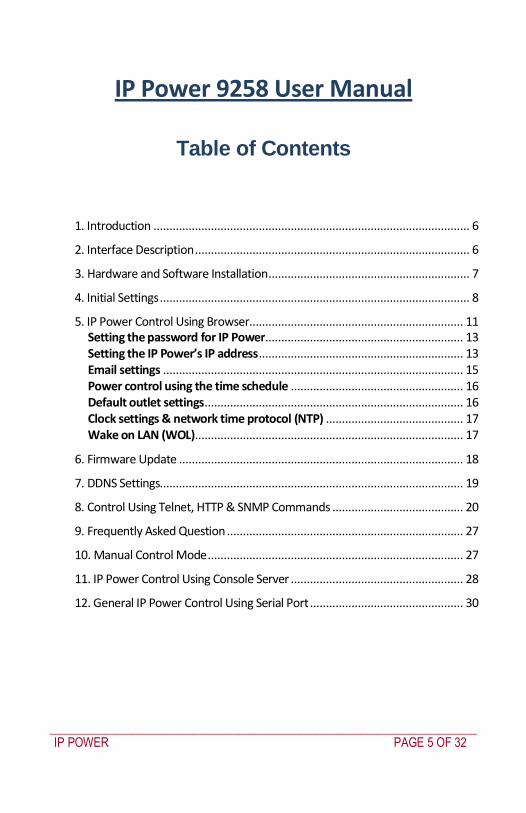
_____________________________________________________________________________
IP POWER PAGE 6 OF 32
1 Introduction
The IP power 9258 is a web browser controlled power switch that can be used easily for industrial or commercial power control With the remote network control technology a user connected to the local area network or Internet can query and control the power supply of attached equipment There is no special software required Maximum rated voltage for each of the 4 outlets 250V AC 24V DC Maximum rated current total 15A ACDC (9258T) 10A ACDC (9258S) Maximum rated current per individual outlet 6A ACDC Action delay max 10ms Operating temperature 0 ~ 70degC IP Power model 9258S - for EUAUUK for 220-250V use power (IN) cable at 10A current Max output current 10A (total) 6A (individual)
IP Power model 9258T - for USTWJP for 100-120V use power (IN) cable at 15A current Max output current 15A (total) 6A (individual)
2 Interface Description
IP Power 9258 front interface (from left to right)
RESET Self-protect AC reset button IP Power 9258 can cut off the power supply of outlets automatically if there is a short circuit or current
_____________________________________________________________________________
IP POWER PAGE 7 OF 32
overload After the user resolves the problem push the RESET button and the AC power supply will resume
LED 4 LED indicator lights If the LED is on the corresponding outlet is power on
RS232 port During normal operation this displays the power output state If a firmware update fails it displays an IP address where the firmware update can be re-applied Also used for secure out-of-band control with CMIM4000 console server
RJ45 Ethernet port Connects the IP Power to the network
Rear interface port description (from left to right)
90-240VAC power input port
Power switch The ONOFF power switch for the IP Power 9258 itself
OUT1 - OUT4 Four individually switched AC outlets
3 Hardware and Software Installation
Before you start to use the IP Power 9258 please follow the steps below
1) Check the package to make sure the contents are complete
2) Prepare an Ethernet hub or router for accessing the IP Power 9258
3) Check the voltage of the power supply to make sure it is AC 110-240 volt
4) Confirm the specifications of your power cable (For IP Power 9258S for 220-250V use the 10A power cable For IP Power 9258T for 100-120V use the 15A power cable)
Hardware installation
Connect the IP Power to the hub using a Cat5 network cable (for remote control you may then connect the hub or router to the Internet)
Connect the AC IN power adapter to the IP Power
Connect the power adapters of equipment to be controlled to corresponding OUT port of the IP Power
For 220-250V please use power wire which can support 10A current Maximum output current (total) 10A (individual) 6A
_____________________________________________________________________________
IP POWER PAGE 8 OF 32
o For 100-120V please use power wire which can support 15A current Maximum output current (total) 15A (individual) 6A
Power on your PC and the power adapter of IP Power
Software installation
Once yoursquove connected the power supply and network cable to the IP Powerrsquos RJ45 network port install the software by following the steps below
Start your computer insert the IP Power CD and locate the file named ipEditexe
Copy the file to your desktop (or another directory if you prefer)
4 Initial Settings
Ensure you have installed the ipEditexe program as described in the previous section Software Installation
Ensure that your PC is connected to the same network as the IP Power and that the IP Power is powered on
Run ipEditexe by double clicking the ipEdit icon The default Ethernet address of the IP Power will be found and displayed The default name of the IP Power is IP 9258
_____________________________________________________________________________
IP POWER PAGE 9 OF 32
Click IP 9258 in the left of the window and the IP Powerrsquos name and IP address will display in the right hand fields You can rename the IP Power or change its IP address or default gateway address Click Update to apply the new settings The new settings will be working in 20 seconds
Double click the name of the IP Power and your browser window will open and connect to the unit automatically Alternately manually type the IP address of the IP Power into your browser
NOTE
The IP Power 9258rsquos default IP address is 192168050 and its subnet mask is 2552552550 The IP address of your computer should be in the same subnet with that of IP Powerrsquos (by default this subnet is 1921680xxx) so that you can access the IP Power control web pages
Typically you will want to find out the IP address of your PC and set the IP Power to reside on the same subnet To find out the IP address of your PC
Select Start Run then type in cmd in the MS-DOS window type in ipconfig
_____________________________________________________________________________
IP POWER PAGE 10 OF 32
The IP address of the PC is 19216810031 so the IP Power has been set to
192168100168 Both of these addresses are on the 192168100xxx subnet
Alternately you may change the PCrsquos IP address to be on the same subnet as the IP Power (by default 192168050) in Control Panel Network Connections Local Area Connection
Properties Internet Protocol (TCPIP) Properties
The default username and password of IP Power 9258 are
Username admin Password 12345678
PC or server software shutdown
The IP Power 9258 can also safety shutdown a PC or server through the network before being powered off This allows you to remotely shut down a PCserver attached to IP Power 9258 using the usual Windows safe shutdown procedure Before using the software shutdown function please note
You will need to install the IP9258serviceexe program from the IP Power CD as detailed below
If you are running programs such as Microsoft Office the safe shut down may not automatically save open documents or files which may result in lost data
To allow enough time for the PCserver to safely shut down before being powered off please set the delay time at 30 or 60 second on the IP Power control web pages Setup Delay Switch
The PCserver to shut down must be on the same Ethernet network and on the same subnet as the IP Power
Installing IP9258serviceexe
Insert the IP Power CD in the PCserver which is to be enabled for software shutdown
Install the IP9258configexe by selecting the SDK button on the LHS then selecting 9258 SDK in the menu Then double click Shutdown Program and run IP9258configexe On the install menu select the LHS bottom button to place the IP9258Service icon on your desktop Click this icon then select the IP9258configexe program
_____________________________________________________________________________
IP POWER PAGE 11 OF 32
Fill in the fields as follows
IP9258 Address The IP Powerrsquos IP address
HTTP Port The port of the IP Power control web pages ndash this will be 80 unless you have changed it
Username admin
Password The IP Power admin password (default 12345678)
Power Number The OUT power outlet the PCserver is connected through ndash if many PCservers are connected through the one power outlet and are registered with the same IP Power unit they will all be shutdown at the same time
Click Save Change Install Service then Start Service Restart the PCserver then
it will be enabled for software shutdown
5 IP Power Control Using Browser
To access the IP Power control web pages simply type the IP address of the IP Power into your web browserrsquos address field
_____________________________________________________________________________
IP POWER PAGE 12 OF 32
The username is admin and the default password is 12345678 Enter these credentials or the password you have set Click OK to enter the IP Power control web pages
Control the power supply by outlet
IP Power 9258 can control 4 outputs individually or at the same time
Select the Set Power from the left hand menu
You can choose to power off and power on an outlet You may also set the
time to delay before performing the chosen action under Timer by entering the time to delay in seconds and selecting On
Querying the power state of the outlets
Click Set Power again to refresh the status The state of each power outlet is displayed under the Control column
_____________________________________________________________________________
IP POWER PAGE 13 OF 32
System settings with browser
You may set the password IP address e-mail address timer setting perform an online firmware update and set the time of the IP Power through the IP Power control web pages
Setting the password for IP Power
Select Change password from the left hand menu The default password 12345678 You may change it to a password of your choosing (no longer than 8 characters) Click Apply to save the change
NOTE
If you lose or forget the admin password enter the username super user at the log in webpage
and then click OK Then turn the power off for a few seconds before turning the power back on The IP Power will to be reset to using the default password of 12345678 Note There is space between super and user
Setting the IP Powerrsquos IP address
Select Setup from the left hand menu Fill in the new IP Address Subnet Mask Default Gateway and DNS server address If your network has a DHCP server automatically allocating network settings you may choose to enable the IP Powerrsquos DHP Client The Beeper sound may also be enabled or disabled on this page
_____________________________________________________________________________
IP POWER PAGE 14 OF 32
If the IP Power is connected to your Local Area Network (LAN)
You may set a fixed IP address or have it automatically assigned by a DHCP server It is suggested that you use a fixed IP address so that it is always known After changing the IP Powerrsquos IP address type the new address in the address field of your web browser You can also use the ipEditexe tool to locate the IP Power
If the IP Power is connected to the Internet (WAN)
IP Address Enter the IP address provided by your ISP If IP Power is working with a router please refer to the network settings of the router The IP address format is xxxxxxxxxxxx yyyyy where yyyyy means the port number ranging from 1 to 32767
Subnet Mask Enter the Subnet Mask provided by your ISP If the IP Power is working with a router please refer to the network settings of the router Subnet Mask from 0 to 254 ( xxxxxxxxx0 ~ xxxxxxxxx254)
Default gateway Enter the Default Gateway provided by your ISP If the IP Power is working with a router please refer to the network settings of the router
DNS Server Enter the IP address of the DNS server provided by your ISP
DHCP Client Automatically obtain network settings from your ISP
If DHCP is disabled you must set the TCP port and default gateway If DHCP is enabled then the TCP port is preset to 80 (xxxxxxxxxxxx80) and the default gateway will be assigned by the DHCP server
If you specify a TCP port other than 80 enter it after the IP address of the IP Power when accessing the IP Power control web pages eg httpxxxxxxxxxxxxyyyyy
Beeper Setting Enable ndash activate the beeper sounds Disable ndash turn off beep
sounds When controlling the IP Power through the web pages the beeper if enabled beeps once to indicate an action has been successful
HTTP Command Verification specifies the HTTP authentication for the IP Power to use
_____________________________________________________________________________
IP POWER PAGE 15 OF 32
o Cookie +Base64 (allows HTTP command amp SDK control) o Cookie (allows HTTP command amp SDK control)
Email settings
The IP Power can be set to email its IP address to multiple recipients
Mail Server The SMTP server for sending email Please ensure that it is available
POP3Server Incoming Mail Server Enter IP address from your ISP for sending Internet IP address by E-mail
Username The SMTP username for sending email
Password The password for Usernamersquos account Note the password can be no longer than 8 characters
Sender The same of the sender to use This will often be usernameyourdomain
Receiver 1 ndash 3 The email addresses to receive the IP Powerrsquos IP address They will receive an email containing the IP Powerrsquos IP address each time your log in to the IP Power control web pages Each receiver may be no more than 50 characters
Subject The subject of the mail no more than 50 characters
Mail Body Type the content of the mail here It must not be left blank
_____________________________________________________________________________
IP POWER PAGE 16 OF 32
Click Save to save your settings
Power control using the time schedule
The IP Power can be set to power on or off power outlets at specified times Select Power Schedule from the left hand menu
Each power outlet has two rows one for the start of the schedule (eg powering an outlet on) and one for the end of the schedule (eg powering the outlet off two hours later) Additionally the Parameter column determines how regularly the schedule should be applied
Disable
Just Once
Every day
Work days every Monday to Friday
Weekend every Saturday and Sunday
Default outlet settings
When the IP Power is powered on each outlet will have power applied according to the default outlet settings In the example below all power outlets default to OFF when the IP Power is initially powered on
_____________________________________________________________________________
IP POWER PAGE 17 OF 32
Clock settings amp network time protocol (NTP)
You may manually set the IP Powerrsquos internal clock by specifying the year month day hour minutes and seconds
Alternately you may choose to synchronize with an NTP server by entering its IP address and your numeric Time Zone (relative to UTC) If your network or ISP doesnrsquot have an NTP server lists of public NTP servers are available on the web
Wake on LAN (WOL)
Through its network port the IP Power can send a Wake on LAN packet to a shutdown or hibernating PC on your network causing it to power up This facility presumes
1 The PCrsquos motherboard must support the WOL function and it must be enabled in the BIOS (typically under Power Management) The PC must be connected to the same Ethernet network as the IP Power via its network port
2 The PCrsquos network cardrsquos WOL connector must be connected to the motherboard or the network port must be integrated into the motherboard
After setting up the motherboard and network card use the WOL function by following two steps
Go to Network Wakeup on the IP Power control web pages
Enter the MAC address (the network cardrsquos physical address) of the PC and click Send ndash the PC will be powered on
_____________________________________________________________________________
IP POWER PAGE 18 OF 32
NOTE
To find out your network cardrsquos MAC address
Right click on the network connection icon Status Support Details The value in Physical Address is the MAC address
6 Firmware Update
Warning If you have not been advised to update the IP Powerrsquos firmware and do not have a new firmware file please do not go to this page
NOTE Before updating the IP Powerrsquos firmware ensure the IP Power control web pagesrsquo TCP port is set
to 80 (this is the default) otherwise the update may fail
Firmware updates are periodically released to update the functionality of the IP Power To update the IP Powerrsquos firmware select Firmware Update from the left hand menu
The following warning is displayed
_____________________________________________________________________________
IP POWER PAGE 19 OF 32
Warning Do not click Update if you do not have a firmware update file
Click Update the following window is displayed
Click Browse and locate the firmware update file Click Update to begin the update
Note When the update is complete you must wait at least one minute before you restart the IP Power
7 DDNS Settings
When connecting to the Internet the IP address you gain from ISP may be dynamically allocated so it may change each time the Internet connection reconnects This may result in the IP Power becoming uncontactable to remote clients as the new address is unknown Dynamic DNS addresses this issue by updating DNS records whenever the IP address changes The IP Power can utilize the free service provided by DynDNS (httpwwwdyndnscom) for this purpose The IP Power will always be contactable using its DynDNS address (eg ippowerdyndnsorg) regardless of its IP address
_____________________________________________________________________________
IP POWER PAGE 20 OF 32
First create a DynDNS account and create an account Create a dynamic DNS host for the IP Power eg ippowerdyndnsorg On the IP Power select DDNS from the left hand menu Enter the IP address and port of the DynDNS server You can find this out on your PC by selecting Start Run then type in cmd and typing ping wwwdyndnscom Enter the number in brackets (eg 6320819666) followed by 80 to denote the port In Your Domain enter the IP Powerrsquos DynDNS address eg ippowerdyndnsorg Enter the Username and Password for the DynDNS account you created Ensure Enable DDNS is set to TRUE Click Save Now each time the IP Power is powered on or Update Now is clicked the DynDNS address will be updated to the IP Powerrsquos current IP address Note that the change may take several minutes to propagate to your local DNS server If the IP Power cannot reach the DynDNS server without going through a proxy server select TRUE next to Proxy Enable Enter the IP address of the proxy server in Proxy IP and the port in Proxy Port
NOTE
The first time you configure DDNS click Update Now to set the DynDNS address
8 Control Using Telnet HTTP amp SNMP Commands
The IP Power is a principally a browser controlled unit with power control effected over the LAN using HTTP commands or a browser However it also provides alternate methods for directly setting and getting the status of the power outlets through Telnet commands and HTTP commands (which may be useful for controlling the IP Powerrsquos outlets using an automated script) and through SMNP Power outlet status and control using HTTP commands
The format of the HTTP command is
_____________________________________________________________________________
IP POWER PAGE 21 OF 32
httpusernamepasswordabcdSetcmdCMD=command+outlet_id=10+out
let_id=10 Where username The username you use to login to the IP Power (default is admin)
password The password you use to login to the IP Power (default is 12345678)
abcd The IP address of the IP Power (default is 192168050)
command GetPower to read the status (specifying outlets is not required) SetPower to turn on or off the ports (power setting for each outlet must
be specified after the command)
port_id (SetPower only) P60 Port 1 P61 Port 2 P62 Port 3 P63 Port 4 Example 1 The HTTP command httpadmin123456781921680 50SetcmdCMD=GetPower Returns the power status for each outlet in the following format (outlets 5 to 8 may be ignored) lthtmlgtP60=0P61=0P62=0P63=0P64=0P65=0P66=0P67=0lthtmlgt In the above example all outlets are off Example 2 The HTTP command httpadmin12345678192168050SetcmdCMD=SetPower+P60=1+P61=0+P62=0+P63=1
_____________________________________________________________________________
IP POWER PAGE 22 OF 32
Turns the power on for the first (P60) and fourth (P63) outlets and turns power off for the second (P61) and third (P62) outlets Returns the power status for each outlet in the following format lthtmlgtP60=1P61=0P62=0P63=1lthtmlgt Example 3 The HTTP command to control the 9258 operation at a specified time httpusernamepasswordXXXXXXXXXXXXSetcmdCMD=SetSchedule+Power =+YY=+MM=+DD=+HH=+MN=+SS=+PARAM=+ONOFF= Where Control parameters are 1A 1B 2A 2B 3A 3B 4A 4B A = connect power B = disconnect power YY=+MM=+DD=+HH=+MN=+SS= time parameter YY year (20YY) 01 = 2001 MM month (0 1-12) DD date (01-31) HH hour (24 hours 0- 23) MN minute (1-60) SS second (1-60) PARAM= time schedule parameter Parameter list as follows 128 Once only 127 Every day 31 Week days (Monday to Friday) 96 Weekend days (Saturday and Sunday) ONOFF= operate parameter 0 open 1 close For example
_____________________________________________________________________________
IP POWER PAGE 23 OF 32
http admin12345678192168110SetcmdCMD=SetSchedule+Power=1A+YY=2009+MM=02+DD=16+HH=06+MN=02+SS=16+PARAM=128+ONOFF=1 The above command controls the IP Power at IP address 19216810 user name is admin and password is 12345678 This 9258 will connect power of outlet 1 (p60) once only on 16th February 2009 at 602 am
NOTE Use + to separate each parameter eg to simply power on outlet 1 httpadmin12345678192168110SetcmdCMD=SetPower+P60=1
The command syntax is case sensitive so be selective when using upper and lower case in command format The free tool wget is useful for sending these HTTP commands For example
to send the command in Example 1 you could use wget ndashO -httpadmin12345678192168050SetcmdCMD=SetPower+P60=1+P61=0+P62=0+P63=1
Power outlet status and control using Telnet
Under DOS mode type ldquo Cgttelnet [IP9258] ldquo
To log in to the device use the syntax login=password
Typing help will give you the other commands that are available for the 9258 in telnet
_____________________________________________________________________________
IP POWER PAGE 24 OF 32
The getpower command reports the status of power outlets 1-4 The setpower command controls the power outlets 1-4 with ldquo0rdquo turning power off and ldquo1rdquo turning power on Example 1 setpower =11110000 (This will turn on power 1-4) Example 2 setpower =11000000 (This turns on power on 1 amp 2 and turns off power 3 amp 4)
NOTE Only the first four numbers are used You can select from 0 to turn off the power to 1 to turn on the
power However with 155 the syntax requires to use eight separte digits If you only use four digits the command will not work properly
_____________________________________________________________________________
IP POWER PAGE 25 OF 32
Power outlet status and control using SNMP
Reading status
snmpget -v 1 -c public 192168155 1361419258210 (read status of Power1)
snmpget -v 1 -c public 192168155 1361419258220 (read status of Power2) snmpget -v 1 -c public 192168155 1361419258230 (read status of Power3) snmpget -v 1 -c public 192168155 1361419258240 (read status of Power4)
(Return value as ldquoINTEGER 1 rdquo means power ON Return value as ldquoINTEGER 0 rdquo means power OFF)
_____________________________________________________________________________
IP POWER PAGE 26 OF 32
Control outlet command
snmpset -v 1 -c public 192168155 1361419258210 integer 1 (turn on Power1) snmpset -v 1 -c public 192168155 1361419258220 integer 0 (turn off Power2)
snmpset -v 1 -c public 192168155 1361419258230 integer 1 (turn on Power3) snmpset -v 1 -c public 192168155 1361419258240 integer 0 (turn off Power4)
Power cycle outlet command snmpset -v 1 -c public 192168155 1361419258310 integer 1 (powercycle No1)
snmpset -v 1 -c public 192168155 1361419258320 integer 1 (powercycle No2) snmpset -v 1 -c public 192168155 1361419258330 integer 1 (powercycle No3)
_____________________________________________________________________________
IP POWER PAGE 27 OF 32
snmpset -v 1 -c public 192168155 1361419258340 integer 1 (powercycle No4)
If the power is on the outlet will turn ldquoOFF to ON ldquo when the power cycle command is placed However if powered off the outlet will turn ldquoON to OFF to ON ldquo when place power cycle command
9 Frequently Asked Question
Q1 I forgot the password and can not enter the administration page now what can I do A1 Use the username super user when logging in to the webpage and then click OK Turn the IP Power off for a few seconds the turn it back on The default username of admin and password of 12345678 will be restored Note there is a space between super and user
10 Manual Control Mode
The IP Power is generally controlled from a local or remote computer however the outlets can also be controlled manually
NOTE
Before using the manual control function it is necessary to UNPLUG DISCONNECT all of the 4 outlets
To obtain manual control
_____________________________________________________________________________
IP POWER PAGE 28 OF 32
Press and hold the ONOFF button (depicted below) for a full 5 seconds or until a sustained beep noise is heard ndash this enables manual control mode which can be identified by the flashing outlet lights
The outlet light that is not flashing is the one currently under manual control ndash this outlet can be turned on or off by pressing the ONOFF button
To select an alternate outlet to control press the Cycle button (labeled with a circle with arrows on it)
To disable manual control mode press and hold the ONOFF button for 5 seconds or until you can hear a sustained beep noise ndash signifying the deactivation of manual control mode
Cycle (left) Select power outlet to manually control
ONOFF (right) Press and hold to enabledisable manual control mode press to turn onoff the outlet selected by the cycle button
11 IP Power Control Using Console Server
The IP Power 9258 is a simple browser controlled power switch without the security features needed for open public network connection Nor does it have any remote out-of-band dial-in support
However the IP Power can be configured securely and its outlets can be controlled in-band and out of band when used in conjunction with an Opengear console server
Out of band access
The Opengear console server provides secure remoteout-of-band access through a dial in modem (or through an alternate broadband connection) To configure the console server for dial-in access
_____________________________________________________________________________
IP POWER PAGE 29 OF 32
Connect a modem to the consolemodem port and configure the console server for dial-in
The IP Power can then be network or serially connected to the console server
SSH tunneled control through the Console Server
If the IP Power is connected on the remote LAN with the console server then it can be browser controlled
Configure the console server with the IP Power as a HTTP accessible Host This Managed Device can then be remotely controlled securely using SSH tunneling (SDT)
Configure the remote SDTConnector client to access the gateway (console server) and then to connect to the IP Power using HTTP (refer wwwopengearcomfaq267html for details)
Console Server serial control
The IP Power is a principally a browser controlled unit and its RS232 serial port mainly provides diagnostic and status information (eg sending out its IP address and power on messages during Power On Self Test) However the IP Power serial port also supports emergency power control To configure the IP Power for serial control
Connect the IP Power 9258s CONSOLE RS232 port to one of the console server serial ports (for CM4001 2 this interconnection will use a standard UTP Cat 5 cable with a 319000 adapter at each end and all other console servers will only require one 319000 adaptor)
Configured the console server serial port with a serially controlled PDU
_____________________________________________________________________________
IP POWER PAGE 30 OF 32
The IP Power outlets are then controlled by securely (HTTPS) accessing the Manage Power menu on the console server Management Console (refer wwwopengearcomfaq231html for details)
NOTE
The outlet control commands are sent from the console server to the IP Power over the serial port
The combination of out of band access and IP Power serial port control can be particularly useful in managing remote sites where a DSL router (interconnect the office LAN and the internet) may have become dysfunctional requiring a power reset
12 General IP Power Control Using Serial Port
The IP Power RS232 serial port mainly provides diagnostic and status information however the serial port can be used for emergency power control as covered in the previous section
Usage power-ip9258 ltportgt ltoutletgt [outlet] on|off|status
The serial control script below is used in the console server and should work on a normal Linux box
binsh
out_udelay=50000
_____________________________________________________________________________
IP POWER PAGE 31 OF 32
out_retries=3
in_udelay=100000
in_retries=10
port=$1
outlets=$2 cmd=$3 tmpfile=tmptmp$$
if [[ -z $port ]] || [[ -z $outlets ]] || [[ -z $cmd ]] then appname=`basename $0`
echo Usage $appname ltportgt ltoutletgt [outlet] on|off|status exit 1 fi
function ipp_chat () out=$1
in=$2 cat $port gt $tmpfile amp
cat_pid=$ trap rm $tmpfile kill $cat_pid EXIT
for (( i=0 i lt $out_retries i++ )) do for (( j = 0 j lt $out j++ )) do usleep $out_udelay
echo -n $out$j1 gt $port done echo gt $port
for (( j=0 j lt $in_retries j++ )) do usleep $in_udelay line=`grep $in $tmpfile`
if [[ -n $line ]] then break 2 fi
done done
rm $tmpfile kill $cat_pid
if [[ -n $line ]] then echo $line else
echo Command failed ($out) exit 1 fi
Suppress error messages from the shell
exec 2gt devnull Set up the serial port for the IP Power
_____________________________________________________________________________
IP POWER PAGE 32 OF 32
stty 14004cbea3031c7f15401011131a012f17160000000000000
000 lt $port Enable serial command mode
ipp_chat 0ADEBUG9258Z IP9258 DEBUG ON ampgt devnull Get current status
status_nibble=`ipp_chat 0Ap06Z p6 | sed sp6()1g`
Send the command the least significant bit is port 1 the most significant is port 4 A value of 0 is on 1 is off
outlet_mask=0 for o in $outlets do outlet_bit=$(( 1ltlt $o-1 ))
outlet_mask=$(( outlet_mask | $outlet_bit )) done status_nibble=`printf d 0x$status_nibble`
if [[ $cmd == on ]] then echo Powering on outlet $outlets status_nibble=`printf X $(( $status_nibble amp ~$outlet_mask ))`
ipp_chat 0AP06F$status_nibbleZ P6=F$status_nibble ampgt devnull echo Outlet $outlets powered on
elif [[ $cmd == off ]] then echo Powering off outlet $outlets status_nibble=`printf X $(( $status_nibble | $outlet_mask ))`
ipp_chat 0AP06F$status_nibbleZ P6=F$status_nibble ampgt devnull echo Outlet $outlets powered off
else for o in $outlets do outlet_bit=$(( 1ltlt $o-1 ))
echo -n Outlet $o is if [[ $(( $status_nibble amp $outlet_bit )) -eq $outlet_bit ]] then echo off
else echo on fi
done fi
Disable serial command mode ipp_chat 0ADEBUG0FFZ IP9258 DEBUG OFF ampgt devnull exit 0
_____________________________________________________________________________
IP POWER PAGE 7 OF 32
overload After the user resolves the problem push the RESET button and the AC power supply will resume
LED 4 LED indicator lights If the LED is on the corresponding outlet is power on
RS232 port During normal operation this displays the power output state If a firmware update fails it displays an IP address where the firmware update can be re-applied Also used for secure out-of-band control with CMIM4000 console server
RJ45 Ethernet port Connects the IP Power to the network
Rear interface port description (from left to right)
90-240VAC power input port
Power switch The ONOFF power switch for the IP Power 9258 itself
OUT1 - OUT4 Four individually switched AC outlets
3 Hardware and Software Installation
Before you start to use the IP Power 9258 please follow the steps below
1) Check the package to make sure the contents are complete
2) Prepare an Ethernet hub or router for accessing the IP Power 9258
3) Check the voltage of the power supply to make sure it is AC 110-240 volt
4) Confirm the specifications of your power cable (For IP Power 9258S for 220-250V use the 10A power cable For IP Power 9258T for 100-120V use the 15A power cable)
Hardware installation
Connect the IP Power to the hub using a Cat5 network cable (for remote control you may then connect the hub or router to the Internet)
Connect the AC IN power adapter to the IP Power
Connect the power adapters of equipment to be controlled to corresponding OUT port of the IP Power
For 220-250V please use power wire which can support 10A current Maximum output current (total) 10A (individual) 6A
_____________________________________________________________________________
IP POWER PAGE 8 OF 32
o For 100-120V please use power wire which can support 15A current Maximum output current (total) 15A (individual) 6A
Power on your PC and the power adapter of IP Power
Software installation
Once yoursquove connected the power supply and network cable to the IP Powerrsquos RJ45 network port install the software by following the steps below
Start your computer insert the IP Power CD and locate the file named ipEditexe
Copy the file to your desktop (or another directory if you prefer)
4 Initial Settings
Ensure you have installed the ipEditexe program as described in the previous section Software Installation
Ensure that your PC is connected to the same network as the IP Power and that the IP Power is powered on
Run ipEditexe by double clicking the ipEdit icon The default Ethernet address of the IP Power will be found and displayed The default name of the IP Power is IP 9258
_____________________________________________________________________________
IP POWER PAGE 9 OF 32
Click IP 9258 in the left of the window and the IP Powerrsquos name and IP address will display in the right hand fields You can rename the IP Power or change its IP address or default gateway address Click Update to apply the new settings The new settings will be working in 20 seconds
Double click the name of the IP Power and your browser window will open and connect to the unit automatically Alternately manually type the IP address of the IP Power into your browser
NOTE
The IP Power 9258rsquos default IP address is 192168050 and its subnet mask is 2552552550 The IP address of your computer should be in the same subnet with that of IP Powerrsquos (by default this subnet is 1921680xxx) so that you can access the IP Power control web pages
Typically you will want to find out the IP address of your PC and set the IP Power to reside on the same subnet To find out the IP address of your PC
Select Start Run then type in cmd in the MS-DOS window type in ipconfig
_____________________________________________________________________________
IP POWER PAGE 10 OF 32
The IP address of the PC is 19216810031 so the IP Power has been set to
192168100168 Both of these addresses are on the 192168100xxx subnet
Alternately you may change the PCrsquos IP address to be on the same subnet as the IP Power (by default 192168050) in Control Panel Network Connections Local Area Connection
Properties Internet Protocol (TCPIP) Properties
The default username and password of IP Power 9258 are
Username admin Password 12345678
PC or server software shutdown
The IP Power 9258 can also safety shutdown a PC or server through the network before being powered off This allows you to remotely shut down a PCserver attached to IP Power 9258 using the usual Windows safe shutdown procedure Before using the software shutdown function please note
You will need to install the IP9258serviceexe program from the IP Power CD as detailed below
If you are running programs such as Microsoft Office the safe shut down may not automatically save open documents or files which may result in lost data
To allow enough time for the PCserver to safely shut down before being powered off please set the delay time at 30 or 60 second on the IP Power control web pages Setup Delay Switch
The PCserver to shut down must be on the same Ethernet network and on the same subnet as the IP Power
Installing IP9258serviceexe
Insert the IP Power CD in the PCserver which is to be enabled for software shutdown
Install the IP9258configexe by selecting the SDK button on the LHS then selecting 9258 SDK in the menu Then double click Shutdown Program and run IP9258configexe On the install menu select the LHS bottom button to place the IP9258Service icon on your desktop Click this icon then select the IP9258configexe program
_____________________________________________________________________________
IP POWER PAGE 11 OF 32
Fill in the fields as follows
IP9258 Address The IP Powerrsquos IP address
HTTP Port The port of the IP Power control web pages ndash this will be 80 unless you have changed it
Username admin
Password The IP Power admin password (default 12345678)
Power Number The OUT power outlet the PCserver is connected through ndash if many PCservers are connected through the one power outlet and are registered with the same IP Power unit they will all be shutdown at the same time
Click Save Change Install Service then Start Service Restart the PCserver then
it will be enabled for software shutdown
5 IP Power Control Using Browser
To access the IP Power control web pages simply type the IP address of the IP Power into your web browserrsquos address field
_____________________________________________________________________________
IP POWER PAGE 12 OF 32
The username is admin and the default password is 12345678 Enter these credentials or the password you have set Click OK to enter the IP Power control web pages
Control the power supply by outlet
IP Power 9258 can control 4 outputs individually or at the same time
Select the Set Power from the left hand menu
You can choose to power off and power on an outlet You may also set the
time to delay before performing the chosen action under Timer by entering the time to delay in seconds and selecting On
Querying the power state of the outlets
Click Set Power again to refresh the status The state of each power outlet is displayed under the Control column
_____________________________________________________________________________
IP POWER PAGE 13 OF 32
System settings with browser
You may set the password IP address e-mail address timer setting perform an online firmware update and set the time of the IP Power through the IP Power control web pages
Setting the password for IP Power
Select Change password from the left hand menu The default password 12345678 You may change it to a password of your choosing (no longer than 8 characters) Click Apply to save the change
NOTE
If you lose or forget the admin password enter the username super user at the log in webpage
and then click OK Then turn the power off for a few seconds before turning the power back on The IP Power will to be reset to using the default password of 12345678 Note There is space between super and user
Setting the IP Powerrsquos IP address
Select Setup from the left hand menu Fill in the new IP Address Subnet Mask Default Gateway and DNS server address If your network has a DHCP server automatically allocating network settings you may choose to enable the IP Powerrsquos DHP Client The Beeper sound may also be enabled or disabled on this page
_____________________________________________________________________________
IP POWER PAGE 14 OF 32
If the IP Power is connected to your Local Area Network (LAN)
You may set a fixed IP address or have it automatically assigned by a DHCP server It is suggested that you use a fixed IP address so that it is always known After changing the IP Powerrsquos IP address type the new address in the address field of your web browser You can also use the ipEditexe tool to locate the IP Power
If the IP Power is connected to the Internet (WAN)
IP Address Enter the IP address provided by your ISP If IP Power is working with a router please refer to the network settings of the router The IP address format is xxxxxxxxxxxx yyyyy where yyyyy means the port number ranging from 1 to 32767
Subnet Mask Enter the Subnet Mask provided by your ISP If the IP Power is working with a router please refer to the network settings of the router Subnet Mask from 0 to 254 ( xxxxxxxxx0 ~ xxxxxxxxx254)
Default gateway Enter the Default Gateway provided by your ISP If the IP Power is working with a router please refer to the network settings of the router
DNS Server Enter the IP address of the DNS server provided by your ISP
DHCP Client Automatically obtain network settings from your ISP
If DHCP is disabled you must set the TCP port and default gateway If DHCP is enabled then the TCP port is preset to 80 (xxxxxxxxxxxx80) and the default gateway will be assigned by the DHCP server
If you specify a TCP port other than 80 enter it after the IP address of the IP Power when accessing the IP Power control web pages eg httpxxxxxxxxxxxxyyyyy
Beeper Setting Enable ndash activate the beeper sounds Disable ndash turn off beep
sounds When controlling the IP Power through the web pages the beeper if enabled beeps once to indicate an action has been successful
HTTP Command Verification specifies the HTTP authentication for the IP Power to use
_____________________________________________________________________________
IP POWER PAGE 15 OF 32
o Cookie +Base64 (allows HTTP command amp SDK control) o Cookie (allows HTTP command amp SDK control)
Email settings
The IP Power can be set to email its IP address to multiple recipients
Mail Server The SMTP server for sending email Please ensure that it is available
POP3Server Incoming Mail Server Enter IP address from your ISP for sending Internet IP address by E-mail
Username The SMTP username for sending email
Password The password for Usernamersquos account Note the password can be no longer than 8 characters
Sender The same of the sender to use This will often be usernameyourdomain
Receiver 1 ndash 3 The email addresses to receive the IP Powerrsquos IP address They will receive an email containing the IP Powerrsquos IP address each time your log in to the IP Power control web pages Each receiver may be no more than 50 characters
Subject The subject of the mail no more than 50 characters
Mail Body Type the content of the mail here It must not be left blank
_____________________________________________________________________________
IP POWER PAGE 16 OF 32
Click Save to save your settings
Power control using the time schedule
The IP Power can be set to power on or off power outlets at specified times Select Power Schedule from the left hand menu
Each power outlet has two rows one for the start of the schedule (eg powering an outlet on) and one for the end of the schedule (eg powering the outlet off two hours later) Additionally the Parameter column determines how regularly the schedule should be applied
Disable
Just Once
Every day
Work days every Monday to Friday
Weekend every Saturday and Sunday
Default outlet settings
When the IP Power is powered on each outlet will have power applied according to the default outlet settings In the example below all power outlets default to OFF when the IP Power is initially powered on
_____________________________________________________________________________
IP POWER PAGE 17 OF 32
Clock settings amp network time protocol (NTP)
You may manually set the IP Powerrsquos internal clock by specifying the year month day hour minutes and seconds
Alternately you may choose to synchronize with an NTP server by entering its IP address and your numeric Time Zone (relative to UTC) If your network or ISP doesnrsquot have an NTP server lists of public NTP servers are available on the web
Wake on LAN (WOL)
Through its network port the IP Power can send a Wake on LAN packet to a shutdown or hibernating PC on your network causing it to power up This facility presumes
1 The PCrsquos motherboard must support the WOL function and it must be enabled in the BIOS (typically under Power Management) The PC must be connected to the same Ethernet network as the IP Power via its network port
2 The PCrsquos network cardrsquos WOL connector must be connected to the motherboard or the network port must be integrated into the motherboard
After setting up the motherboard and network card use the WOL function by following two steps
Go to Network Wakeup on the IP Power control web pages
Enter the MAC address (the network cardrsquos physical address) of the PC and click Send ndash the PC will be powered on
_____________________________________________________________________________
IP POWER PAGE 18 OF 32
NOTE
To find out your network cardrsquos MAC address
Right click on the network connection icon Status Support Details The value in Physical Address is the MAC address
6 Firmware Update
Warning If you have not been advised to update the IP Powerrsquos firmware and do not have a new firmware file please do not go to this page
NOTE Before updating the IP Powerrsquos firmware ensure the IP Power control web pagesrsquo TCP port is set
to 80 (this is the default) otherwise the update may fail
Firmware updates are periodically released to update the functionality of the IP Power To update the IP Powerrsquos firmware select Firmware Update from the left hand menu
The following warning is displayed
_____________________________________________________________________________
IP POWER PAGE 19 OF 32
Warning Do not click Update if you do not have a firmware update file
Click Update the following window is displayed
Click Browse and locate the firmware update file Click Update to begin the update
Note When the update is complete you must wait at least one minute before you restart the IP Power
7 DDNS Settings
When connecting to the Internet the IP address you gain from ISP may be dynamically allocated so it may change each time the Internet connection reconnects This may result in the IP Power becoming uncontactable to remote clients as the new address is unknown Dynamic DNS addresses this issue by updating DNS records whenever the IP address changes The IP Power can utilize the free service provided by DynDNS (httpwwwdyndnscom) for this purpose The IP Power will always be contactable using its DynDNS address (eg ippowerdyndnsorg) regardless of its IP address
_____________________________________________________________________________
IP POWER PAGE 20 OF 32
First create a DynDNS account and create an account Create a dynamic DNS host for the IP Power eg ippowerdyndnsorg On the IP Power select DDNS from the left hand menu Enter the IP address and port of the DynDNS server You can find this out on your PC by selecting Start Run then type in cmd and typing ping wwwdyndnscom Enter the number in brackets (eg 6320819666) followed by 80 to denote the port In Your Domain enter the IP Powerrsquos DynDNS address eg ippowerdyndnsorg Enter the Username and Password for the DynDNS account you created Ensure Enable DDNS is set to TRUE Click Save Now each time the IP Power is powered on or Update Now is clicked the DynDNS address will be updated to the IP Powerrsquos current IP address Note that the change may take several minutes to propagate to your local DNS server If the IP Power cannot reach the DynDNS server without going through a proxy server select TRUE next to Proxy Enable Enter the IP address of the proxy server in Proxy IP and the port in Proxy Port
NOTE
The first time you configure DDNS click Update Now to set the DynDNS address
8 Control Using Telnet HTTP amp SNMP Commands
The IP Power is a principally a browser controlled unit with power control effected over the LAN using HTTP commands or a browser However it also provides alternate methods for directly setting and getting the status of the power outlets through Telnet commands and HTTP commands (which may be useful for controlling the IP Powerrsquos outlets using an automated script) and through SMNP Power outlet status and control using HTTP commands
The format of the HTTP command is
_____________________________________________________________________________
IP POWER PAGE 21 OF 32
httpusernamepasswordabcdSetcmdCMD=command+outlet_id=10+out
let_id=10 Where username The username you use to login to the IP Power (default is admin)
password The password you use to login to the IP Power (default is 12345678)
abcd The IP address of the IP Power (default is 192168050)
command GetPower to read the status (specifying outlets is not required) SetPower to turn on or off the ports (power setting for each outlet must
be specified after the command)
port_id (SetPower only) P60 Port 1 P61 Port 2 P62 Port 3 P63 Port 4 Example 1 The HTTP command httpadmin123456781921680 50SetcmdCMD=GetPower Returns the power status for each outlet in the following format (outlets 5 to 8 may be ignored) lthtmlgtP60=0P61=0P62=0P63=0P64=0P65=0P66=0P67=0lthtmlgt In the above example all outlets are off Example 2 The HTTP command httpadmin12345678192168050SetcmdCMD=SetPower+P60=1+P61=0+P62=0+P63=1
_____________________________________________________________________________
IP POWER PAGE 22 OF 32
Turns the power on for the first (P60) and fourth (P63) outlets and turns power off for the second (P61) and third (P62) outlets Returns the power status for each outlet in the following format lthtmlgtP60=1P61=0P62=0P63=1lthtmlgt Example 3 The HTTP command to control the 9258 operation at a specified time httpusernamepasswordXXXXXXXXXXXXSetcmdCMD=SetSchedule+Power =+YY=+MM=+DD=+HH=+MN=+SS=+PARAM=+ONOFF= Where Control parameters are 1A 1B 2A 2B 3A 3B 4A 4B A = connect power B = disconnect power YY=+MM=+DD=+HH=+MN=+SS= time parameter YY year (20YY) 01 = 2001 MM month (0 1-12) DD date (01-31) HH hour (24 hours 0- 23) MN minute (1-60) SS second (1-60) PARAM= time schedule parameter Parameter list as follows 128 Once only 127 Every day 31 Week days (Monday to Friday) 96 Weekend days (Saturday and Sunday) ONOFF= operate parameter 0 open 1 close For example
_____________________________________________________________________________
IP POWER PAGE 23 OF 32
http admin12345678192168110SetcmdCMD=SetSchedule+Power=1A+YY=2009+MM=02+DD=16+HH=06+MN=02+SS=16+PARAM=128+ONOFF=1 The above command controls the IP Power at IP address 19216810 user name is admin and password is 12345678 This 9258 will connect power of outlet 1 (p60) once only on 16th February 2009 at 602 am
NOTE Use + to separate each parameter eg to simply power on outlet 1 httpadmin12345678192168110SetcmdCMD=SetPower+P60=1
The command syntax is case sensitive so be selective when using upper and lower case in command format The free tool wget is useful for sending these HTTP commands For example
to send the command in Example 1 you could use wget ndashO -httpadmin12345678192168050SetcmdCMD=SetPower+P60=1+P61=0+P62=0+P63=1
Power outlet status and control using Telnet
Under DOS mode type ldquo Cgttelnet [IP9258] ldquo
To log in to the device use the syntax login=password
Typing help will give you the other commands that are available for the 9258 in telnet
_____________________________________________________________________________
IP POWER PAGE 24 OF 32
The getpower command reports the status of power outlets 1-4 The setpower command controls the power outlets 1-4 with ldquo0rdquo turning power off and ldquo1rdquo turning power on Example 1 setpower =11110000 (This will turn on power 1-4) Example 2 setpower =11000000 (This turns on power on 1 amp 2 and turns off power 3 amp 4)
NOTE Only the first four numbers are used You can select from 0 to turn off the power to 1 to turn on the
power However with 155 the syntax requires to use eight separte digits If you only use four digits the command will not work properly
_____________________________________________________________________________
IP POWER PAGE 25 OF 32
Power outlet status and control using SNMP
Reading status
snmpget -v 1 -c public 192168155 1361419258210 (read status of Power1)
snmpget -v 1 -c public 192168155 1361419258220 (read status of Power2) snmpget -v 1 -c public 192168155 1361419258230 (read status of Power3) snmpget -v 1 -c public 192168155 1361419258240 (read status of Power4)
(Return value as ldquoINTEGER 1 rdquo means power ON Return value as ldquoINTEGER 0 rdquo means power OFF)
_____________________________________________________________________________
IP POWER PAGE 26 OF 32
Control outlet command
snmpset -v 1 -c public 192168155 1361419258210 integer 1 (turn on Power1) snmpset -v 1 -c public 192168155 1361419258220 integer 0 (turn off Power2)
snmpset -v 1 -c public 192168155 1361419258230 integer 1 (turn on Power3) snmpset -v 1 -c public 192168155 1361419258240 integer 0 (turn off Power4)
Power cycle outlet command snmpset -v 1 -c public 192168155 1361419258310 integer 1 (powercycle No1)
snmpset -v 1 -c public 192168155 1361419258320 integer 1 (powercycle No2) snmpset -v 1 -c public 192168155 1361419258330 integer 1 (powercycle No3)
_____________________________________________________________________________
IP POWER PAGE 27 OF 32
snmpset -v 1 -c public 192168155 1361419258340 integer 1 (powercycle No4)
If the power is on the outlet will turn ldquoOFF to ON ldquo when the power cycle command is placed However if powered off the outlet will turn ldquoON to OFF to ON ldquo when place power cycle command
9 Frequently Asked Question
Q1 I forgot the password and can not enter the administration page now what can I do A1 Use the username super user when logging in to the webpage and then click OK Turn the IP Power off for a few seconds the turn it back on The default username of admin and password of 12345678 will be restored Note there is a space between super and user
10 Manual Control Mode
The IP Power is generally controlled from a local or remote computer however the outlets can also be controlled manually
NOTE
Before using the manual control function it is necessary to UNPLUG DISCONNECT all of the 4 outlets
To obtain manual control
_____________________________________________________________________________
IP POWER PAGE 28 OF 32
Press and hold the ONOFF button (depicted below) for a full 5 seconds or until a sustained beep noise is heard ndash this enables manual control mode which can be identified by the flashing outlet lights
The outlet light that is not flashing is the one currently under manual control ndash this outlet can be turned on or off by pressing the ONOFF button
To select an alternate outlet to control press the Cycle button (labeled with a circle with arrows on it)
To disable manual control mode press and hold the ONOFF button for 5 seconds or until you can hear a sustained beep noise ndash signifying the deactivation of manual control mode
Cycle (left) Select power outlet to manually control
ONOFF (right) Press and hold to enabledisable manual control mode press to turn onoff the outlet selected by the cycle button
11 IP Power Control Using Console Server
The IP Power 9258 is a simple browser controlled power switch without the security features needed for open public network connection Nor does it have any remote out-of-band dial-in support
However the IP Power can be configured securely and its outlets can be controlled in-band and out of band when used in conjunction with an Opengear console server
Out of band access
The Opengear console server provides secure remoteout-of-band access through a dial in modem (or through an alternate broadband connection) To configure the console server for dial-in access
_____________________________________________________________________________
IP POWER PAGE 29 OF 32
Connect a modem to the consolemodem port and configure the console server for dial-in
The IP Power can then be network or serially connected to the console server
SSH tunneled control through the Console Server
If the IP Power is connected on the remote LAN with the console server then it can be browser controlled
Configure the console server with the IP Power as a HTTP accessible Host This Managed Device can then be remotely controlled securely using SSH tunneling (SDT)
Configure the remote SDTConnector client to access the gateway (console server) and then to connect to the IP Power using HTTP (refer wwwopengearcomfaq267html for details)
Console Server serial control
The IP Power is a principally a browser controlled unit and its RS232 serial port mainly provides diagnostic and status information (eg sending out its IP address and power on messages during Power On Self Test) However the IP Power serial port also supports emergency power control To configure the IP Power for serial control
Connect the IP Power 9258s CONSOLE RS232 port to one of the console server serial ports (for CM4001 2 this interconnection will use a standard UTP Cat 5 cable with a 319000 adapter at each end and all other console servers will only require one 319000 adaptor)
Configured the console server serial port with a serially controlled PDU
_____________________________________________________________________________
IP POWER PAGE 30 OF 32
The IP Power outlets are then controlled by securely (HTTPS) accessing the Manage Power menu on the console server Management Console (refer wwwopengearcomfaq231html for details)
NOTE
The outlet control commands are sent from the console server to the IP Power over the serial port
The combination of out of band access and IP Power serial port control can be particularly useful in managing remote sites where a DSL router (interconnect the office LAN and the internet) may have become dysfunctional requiring a power reset
12 General IP Power Control Using Serial Port
The IP Power RS232 serial port mainly provides diagnostic and status information however the serial port can be used for emergency power control as covered in the previous section
Usage power-ip9258 ltportgt ltoutletgt [outlet] on|off|status
The serial control script below is used in the console server and should work on a normal Linux box
binsh
out_udelay=50000
_____________________________________________________________________________
IP POWER PAGE 31 OF 32
out_retries=3
in_udelay=100000
in_retries=10
port=$1
outlets=$2 cmd=$3 tmpfile=tmptmp$$
if [[ -z $port ]] || [[ -z $outlets ]] || [[ -z $cmd ]] then appname=`basename $0`
echo Usage $appname ltportgt ltoutletgt [outlet] on|off|status exit 1 fi
function ipp_chat () out=$1
in=$2 cat $port gt $tmpfile amp
cat_pid=$ trap rm $tmpfile kill $cat_pid EXIT
for (( i=0 i lt $out_retries i++ )) do for (( j = 0 j lt $out j++ )) do usleep $out_udelay
echo -n $out$j1 gt $port done echo gt $port
for (( j=0 j lt $in_retries j++ )) do usleep $in_udelay line=`grep $in $tmpfile`
if [[ -n $line ]] then break 2 fi
done done
rm $tmpfile kill $cat_pid
if [[ -n $line ]] then echo $line else
echo Command failed ($out) exit 1 fi
Suppress error messages from the shell
exec 2gt devnull Set up the serial port for the IP Power
_____________________________________________________________________________
IP POWER PAGE 32 OF 32
stty 14004cbea3031c7f15401011131a012f17160000000000000
000 lt $port Enable serial command mode
ipp_chat 0ADEBUG9258Z IP9258 DEBUG ON ampgt devnull Get current status
status_nibble=`ipp_chat 0Ap06Z p6 | sed sp6()1g`
Send the command the least significant bit is port 1 the most significant is port 4 A value of 0 is on 1 is off
outlet_mask=0 for o in $outlets do outlet_bit=$(( 1ltlt $o-1 ))
outlet_mask=$(( outlet_mask | $outlet_bit )) done status_nibble=`printf d 0x$status_nibble`
if [[ $cmd == on ]] then echo Powering on outlet $outlets status_nibble=`printf X $(( $status_nibble amp ~$outlet_mask ))`
ipp_chat 0AP06F$status_nibbleZ P6=F$status_nibble ampgt devnull echo Outlet $outlets powered on
elif [[ $cmd == off ]] then echo Powering off outlet $outlets status_nibble=`printf X $(( $status_nibble | $outlet_mask ))`
ipp_chat 0AP06F$status_nibbleZ P6=F$status_nibble ampgt devnull echo Outlet $outlets powered off
else for o in $outlets do outlet_bit=$(( 1ltlt $o-1 ))
echo -n Outlet $o is if [[ $(( $status_nibble amp $outlet_bit )) -eq $outlet_bit ]] then echo off
else echo on fi
done fi
Disable serial command mode ipp_chat 0ADEBUG0FFZ IP9258 DEBUG OFF ampgt devnull exit 0
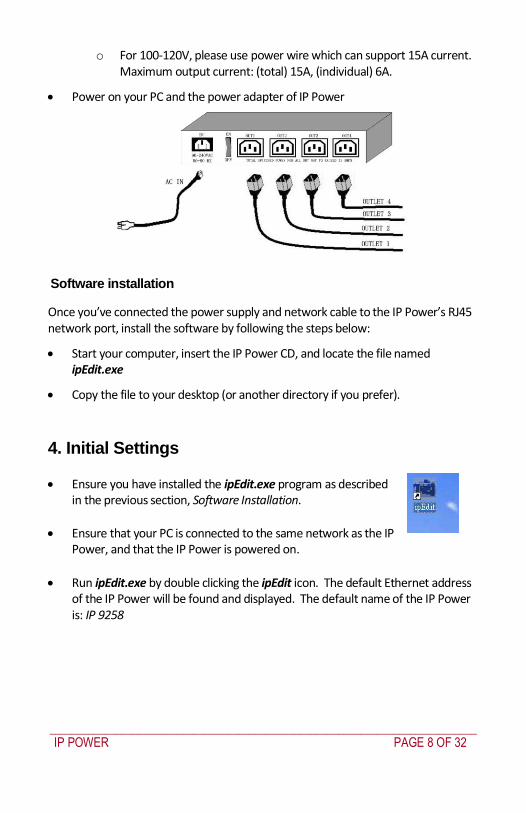
_____________________________________________________________________________
IP POWER PAGE 9 OF 32
Click IP 9258 in the left of the window and the IP Powerrsquos name and IP address will display in the right hand fields You can rename the IP Power or change its IP address or default gateway address Click Update to apply the new settings The new settings will be working in 20 seconds
Double click the name of the IP Power and your browser window will open and connect to the unit automatically Alternately manually type the IP address of the IP Power into your browser
NOTE
The IP Power 9258rsquos default IP address is 192168050 and its subnet mask is 2552552550 The IP address of your computer should be in the same subnet with that of IP Powerrsquos (by default this subnet is 1921680xxx) so that you can access the IP Power control web pages
Typically you will want to find out the IP address of your PC and set the IP Power to reside on the same subnet To find out the IP address of your PC
Select Start Run then type in cmd in the MS-DOS window type in ipconfig
_____________________________________________________________________________
IP POWER PAGE 10 OF 32
The IP address of the PC is 19216810031 so the IP Power has been set to
192168100168 Both of these addresses are on the 192168100xxx subnet
Alternately you may change the PCrsquos IP address to be on the same subnet as the IP Power (by default 192168050) in Control Panel Network Connections Local Area Connection
Properties Internet Protocol (TCPIP) Properties
The default username and password of IP Power 9258 are
Username admin Password 12345678
PC or server software shutdown
The IP Power 9258 can also safety shutdown a PC or server through the network before being powered off This allows you to remotely shut down a PCserver attached to IP Power 9258 using the usual Windows safe shutdown procedure Before using the software shutdown function please note
You will need to install the IP9258serviceexe program from the IP Power CD as detailed below
If you are running programs such as Microsoft Office the safe shut down may not automatically save open documents or files which may result in lost data
To allow enough time for the PCserver to safely shut down before being powered off please set the delay time at 30 or 60 second on the IP Power control web pages Setup Delay Switch
The PCserver to shut down must be on the same Ethernet network and on the same subnet as the IP Power
Installing IP9258serviceexe
Insert the IP Power CD in the PCserver which is to be enabled for software shutdown
Install the IP9258configexe by selecting the SDK button on the LHS then selecting 9258 SDK in the menu Then double click Shutdown Program and run IP9258configexe On the install menu select the LHS bottom button to place the IP9258Service icon on your desktop Click this icon then select the IP9258configexe program
_____________________________________________________________________________
IP POWER PAGE 11 OF 32
Fill in the fields as follows
IP9258 Address The IP Powerrsquos IP address
HTTP Port The port of the IP Power control web pages ndash this will be 80 unless you have changed it
Username admin
Password The IP Power admin password (default 12345678)
Power Number The OUT power outlet the PCserver is connected through ndash if many PCservers are connected through the one power outlet and are registered with the same IP Power unit they will all be shutdown at the same time
Click Save Change Install Service then Start Service Restart the PCserver then
it will be enabled for software shutdown
5 IP Power Control Using Browser
To access the IP Power control web pages simply type the IP address of the IP Power into your web browserrsquos address field
_____________________________________________________________________________
IP POWER PAGE 12 OF 32
The username is admin and the default password is 12345678 Enter these credentials or the password you have set Click OK to enter the IP Power control web pages
Control the power supply by outlet
IP Power 9258 can control 4 outputs individually or at the same time
Select the Set Power from the left hand menu
You can choose to power off and power on an outlet You may also set the
time to delay before performing the chosen action under Timer by entering the time to delay in seconds and selecting On
Querying the power state of the outlets
Click Set Power again to refresh the status The state of each power outlet is displayed under the Control column
_____________________________________________________________________________
IP POWER PAGE 13 OF 32
System settings with browser
You may set the password IP address e-mail address timer setting perform an online firmware update and set the time of the IP Power through the IP Power control web pages
Setting the password for IP Power
Select Change password from the left hand menu The default password 12345678 You may change it to a password of your choosing (no longer than 8 characters) Click Apply to save the change
NOTE
If you lose or forget the admin password enter the username super user at the log in webpage
and then click OK Then turn the power off for a few seconds before turning the power back on The IP Power will to be reset to using the default password of 12345678 Note There is space between super and user
Setting the IP Powerrsquos IP address
Select Setup from the left hand menu Fill in the new IP Address Subnet Mask Default Gateway and DNS server address If your network has a DHCP server automatically allocating network settings you may choose to enable the IP Powerrsquos DHP Client The Beeper sound may also be enabled or disabled on this page
_____________________________________________________________________________
IP POWER PAGE 14 OF 32
If the IP Power is connected to your Local Area Network (LAN)
You may set a fixed IP address or have it automatically assigned by a DHCP server It is suggested that you use a fixed IP address so that it is always known After changing the IP Powerrsquos IP address type the new address in the address field of your web browser You can also use the ipEditexe tool to locate the IP Power
If the IP Power is connected to the Internet (WAN)
IP Address Enter the IP address provided by your ISP If IP Power is working with a router please refer to the network settings of the router The IP address format is xxxxxxxxxxxx yyyyy where yyyyy means the port number ranging from 1 to 32767
Subnet Mask Enter the Subnet Mask provided by your ISP If the IP Power is working with a router please refer to the network settings of the router Subnet Mask from 0 to 254 ( xxxxxxxxx0 ~ xxxxxxxxx254)
Default gateway Enter the Default Gateway provided by your ISP If the IP Power is working with a router please refer to the network settings of the router
DNS Server Enter the IP address of the DNS server provided by your ISP
DHCP Client Automatically obtain network settings from your ISP
If DHCP is disabled you must set the TCP port and default gateway If DHCP is enabled then the TCP port is preset to 80 (xxxxxxxxxxxx80) and the default gateway will be assigned by the DHCP server
If you specify a TCP port other than 80 enter it after the IP address of the IP Power when accessing the IP Power control web pages eg httpxxxxxxxxxxxxyyyyy
Beeper Setting Enable ndash activate the beeper sounds Disable ndash turn off beep
sounds When controlling the IP Power through the web pages the beeper if enabled beeps once to indicate an action has been successful
HTTP Command Verification specifies the HTTP authentication for the IP Power to use
_____________________________________________________________________________
IP POWER PAGE 15 OF 32
o Cookie +Base64 (allows HTTP command amp SDK control) o Cookie (allows HTTP command amp SDK control)
Email settings
The IP Power can be set to email its IP address to multiple recipients
Mail Server The SMTP server for sending email Please ensure that it is available
POP3Server Incoming Mail Server Enter IP address from your ISP for sending Internet IP address by E-mail
Username The SMTP username for sending email
Password The password for Usernamersquos account Note the password can be no longer than 8 characters
Sender The same of the sender to use This will often be usernameyourdomain
Receiver 1 ndash 3 The email addresses to receive the IP Powerrsquos IP address They will receive an email containing the IP Powerrsquos IP address each time your log in to the IP Power control web pages Each receiver may be no more than 50 characters
Subject The subject of the mail no more than 50 characters
Mail Body Type the content of the mail here It must not be left blank
_____________________________________________________________________________
IP POWER PAGE 16 OF 32
Click Save to save your settings
Power control using the time schedule
The IP Power can be set to power on or off power outlets at specified times Select Power Schedule from the left hand menu
Each power outlet has two rows one for the start of the schedule (eg powering an outlet on) and one for the end of the schedule (eg powering the outlet off two hours later) Additionally the Parameter column determines how regularly the schedule should be applied
Disable
Just Once
Every day
Work days every Monday to Friday
Weekend every Saturday and Sunday
Default outlet settings
When the IP Power is powered on each outlet will have power applied according to the default outlet settings In the example below all power outlets default to OFF when the IP Power is initially powered on
_____________________________________________________________________________
IP POWER PAGE 17 OF 32
Clock settings amp network time protocol (NTP)
You may manually set the IP Powerrsquos internal clock by specifying the year month day hour minutes and seconds
Alternately you may choose to synchronize with an NTP server by entering its IP address and your numeric Time Zone (relative to UTC) If your network or ISP doesnrsquot have an NTP server lists of public NTP servers are available on the web
Wake on LAN (WOL)
Through its network port the IP Power can send a Wake on LAN packet to a shutdown or hibernating PC on your network causing it to power up This facility presumes
1 The PCrsquos motherboard must support the WOL function and it must be enabled in the BIOS (typically under Power Management) The PC must be connected to the same Ethernet network as the IP Power via its network port
2 The PCrsquos network cardrsquos WOL connector must be connected to the motherboard or the network port must be integrated into the motherboard
After setting up the motherboard and network card use the WOL function by following two steps
Go to Network Wakeup on the IP Power control web pages
Enter the MAC address (the network cardrsquos physical address) of the PC and click Send ndash the PC will be powered on
_____________________________________________________________________________
IP POWER PAGE 18 OF 32
NOTE
To find out your network cardrsquos MAC address
Right click on the network connection icon Status Support Details The value in Physical Address is the MAC address
6 Firmware Update
Warning If you have not been advised to update the IP Powerrsquos firmware and do not have a new firmware file please do not go to this page
NOTE Before updating the IP Powerrsquos firmware ensure the IP Power control web pagesrsquo TCP port is set
to 80 (this is the default) otherwise the update may fail
Firmware updates are periodically released to update the functionality of the IP Power To update the IP Powerrsquos firmware select Firmware Update from the left hand menu
The following warning is displayed
_____________________________________________________________________________
IP POWER PAGE 19 OF 32
Warning Do not click Update if you do not have a firmware update file
Click Update the following window is displayed
Click Browse and locate the firmware update file Click Update to begin the update
Note When the update is complete you must wait at least one minute before you restart the IP Power
7 DDNS Settings
When connecting to the Internet the IP address you gain from ISP may be dynamically allocated so it may change each time the Internet connection reconnects This may result in the IP Power becoming uncontactable to remote clients as the new address is unknown Dynamic DNS addresses this issue by updating DNS records whenever the IP address changes The IP Power can utilize the free service provided by DynDNS (httpwwwdyndnscom) for this purpose The IP Power will always be contactable using its DynDNS address (eg ippowerdyndnsorg) regardless of its IP address
_____________________________________________________________________________
IP POWER PAGE 20 OF 32
First create a DynDNS account and create an account Create a dynamic DNS host for the IP Power eg ippowerdyndnsorg On the IP Power select DDNS from the left hand menu Enter the IP address and port of the DynDNS server You can find this out on your PC by selecting Start Run then type in cmd and typing ping wwwdyndnscom Enter the number in brackets (eg 6320819666) followed by 80 to denote the port In Your Domain enter the IP Powerrsquos DynDNS address eg ippowerdyndnsorg Enter the Username and Password for the DynDNS account you created Ensure Enable DDNS is set to TRUE Click Save Now each time the IP Power is powered on or Update Now is clicked the DynDNS address will be updated to the IP Powerrsquos current IP address Note that the change may take several minutes to propagate to your local DNS server If the IP Power cannot reach the DynDNS server without going through a proxy server select TRUE next to Proxy Enable Enter the IP address of the proxy server in Proxy IP and the port in Proxy Port
NOTE
The first time you configure DDNS click Update Now to set the DynDNS address
8 Control Using Telnet HTTP amp SNMP Commands
The IP Power is a principally a browser controlled unit with power control effected over the LAN using HTTP commands or a browser However it also provides alternate methods for directly setting and getting the status of the power outlets through Telnet commands and HTTP commands (which may be useful for controlling the IP Powerrsquos outlets using an automated script) and through SMNP Power outlet status and control using HTTP commands
The format of the HTTP command is
_____________________________________________________________________________
IP POWER PAGE 21 OF 32
httpusernamepasswordabcdSetcmdCMD=command+outlet_id=10+out
let_id=10 Where username The username you use to login to the IP Power (default is admin)
password The password you use to login to the IP Power (default is 12345678)
abcd The IP address of the IP Power (default is 192168050)
command GetPower to read the status (specifying outlets is not required) SetPower to turn on or off the ports (power setting for each outlet must
be specified after the command)
port_id (SetPower only) P60 Port 1 P61 Port 2 P62 Port 3 P63 Port 4 Example 1 The HTTP command httpadmin123456781921680 50SetcmdCMD=GetPower Returns the power status for each outlet in the following format (outlets 5 to 8 may be ignored) lthtmlgtP60=0P61=0P62=0P63=0P64=0P65=0P66=0P67=0lthtmlgt In the above example all outlets are off Example 2 The HTTP command httpadmin12345678192168050SetcmdCMD=SetPower+P60=1+P61=0+P62=0+P63=1
_____________________________________________________________________________
IP POWER PAGE 22 OF 32
Turns the power on for the first (P60) and fourth (P63) outlets and turns power off for the second (P61) and third (P62) outlets Returns the power status for each outlet in the following format lthtmlgtP60=1P61=0P62=0P63=1lthtmlgt Example 3 The HTTP command to control the 9258 operation at a specified time httpusernamepasswordXXXXXXXXXXXXSetcmdCMD=SetSchedule+Power =+YY=+MM=+DD=+HH=+MN=+SS=+PARAM=+ONOFF= Where Control parameters are 1A 1B 2A 2B 3A 3B 4A 4B A = connect power B = disconnect power YY=+MM=+DD=+HH=+MN=+SS= time parameter YY year (20YY) 01 = 2001 MM month (0 1-12) DD date (01-31) HH hour (24 hours 0- 23) MN minute (1-60) SS second (1-60) PARAM= time schedule parameter Parameter list as follows 128 Once only 127 Every day 31 Week days (Monday to Friday) 96 Weekend days (Saturday and Sunday) ONOFF= operate parameter 0 open 1 close For example
_____________________________________________________________________________
IP POWER PAGE 23 OF 32
http admin12345678192168110SetcmdCMD=SetSchedule+Power=1A+YY=2009+MM=02+DD=16+HH=06+MN=02+SS=16+PARAM=128+ONOFF=1 The above command controls the IP Power at IP address 19216810 user name is admin and password is 12345678 This 9258 will connect power of outlet 1 (p60) once only on 16th February 2009 at 602 am
NOTE Use + to separate each parameter eg to simply power on outlet 1 httpadmin12345678192168110SetcmdCMD=SetPower+P60=1
The command syntax is case sensitive so be selective when using upper and lower case in command format The free tool wget is useful for sending these HTTP commands For example
to send the command in Example 1 you could use wget ndashO -httpadmin12345678192168050SetcmdCMD=SetPower+P60=1+P61=0+P62=0+P63=1
Power outlet status and control using Telnet
Under DOS mode type ldquo Cgttelnet [IP9258] ldquo
To log in to the device use the syntax login=password
Typing help will give you the other commands that are available for the 9258 in telnet
_____________________________________________________________________________
IP POWER PAGE 24 OF 32
The getpower command reports the status of power outlets 1-4 The setpower command controls the power outlets 1-4 with ldquo0rdquo turning power off and ldquo1rdquo turning power on Example 1 setpower =11110000 (This will turn on power 1-4) Example 2 setpower =11000000 (This turns on power on 1 amp 2 and turns off power 3 amp 4)
NOTE Only the first four numbers are used You can select from 0 to turn off the power to 1 to turn on the
power However with 155 the syntax requires to use eight separte digits If you only use four digits the command will not work properly
_____________________________________________________________________________
IP POWER PAGE 25 OF 32
Power outlet status and control using SNMP
Reading status
snmpget -v 1 -c public 192168155 1361419258210 (read status of Power1)
snmpget -v 1 -c public 192168155 1361419258220 (read status of Power2) snmpget -v 1 -c public 192168155 1361419258230 (read status of Power3) snmpget -v 1 -c public 192168155 1361419258240 (read status of Power4)
(Return value as ldquoINTEGER 1 rdquo means power ON Return value as ldquoINTEGER 0 rdquo means power OFF)
_____________________________________________________________________________
IP POWER PAGE 26 OF 32
Control outlet command
snmpset -v 1 -c public 192168155 1361419258210 integer 1 (turn on Power1) snmpset -v 1 -c public 192168155 1361419258220 integer 0 (turn off Power2)
snmpset -v 1 -c public 192168155 1361419258230 integer 1 (turn on Power3) snmpset -v 1 -c public 192168155 1361419258240 integer 0 (turn off Power4)
Power cycle outlet command snmpset -v 1 -c public 192168155 1361419258310 integer 1 (powercycle No1)
snmpset -v 1 -c public 192168155 1361419258320 integer 1 (powercycle No2) snmpset -v 1 -c public 192168155 1361419258330 integer 1 (powercycle No3)
_____________________________________________________________________________
IP POWER PAGE 27 OF 32
snmpset -v 1 -c public 192168155 1361419258340 integer 1 (powercycle No4)
If the power is on the outlet will turn ldquoOFF to ON ldquo when the power cycle command is placed However if powered off the outlet will turn ldquoON to OFF to ON ldquo when place power cycle command
9 Frequently Asked Question
Q1 I forgot the password and can not enter the administration page now what can I do A1 Use the username super user when logging in to the webpage and then click OK Turn the IP Power off for a few seconds the turn it back on The default username of admin and password of 12345678 will be restored Note there is a space between super and user
10 Manual Control Mode
The IP Power is generally controlled from a local or remote computer however the outlets can also be controlled manually
NOTE
Before using the manual control function it is necessary to UNPLUG DISCONNECT all of the 4 outlets
To obtain manual control
_____________________________________________________________________________
IP POWER PAGE 28 OF 32
Press and hold the ONOFF button (depicted below) for a full 5 seconds or until a sustained beep noise is heard ndash this enables manual control mode which can be identified by the flashing outlet lights
The outlet light that is not flashing is the one currently under manual control ndash this outlet can be turned on or off by pressing the ONOFF button
To select an alternate outlet to control press the Cycle button (labeled with a circle with arrows on it)
To disable manual control mode press and hold the ONOFF button for 5 seconds or until you can hear a sustained beep noise ndash signifying the deactivation of manual control mode
Cycle (left) Select power outlet to manually control
ONOFF (right) Press and hold to enabledisable manual control mode press to turn onoff the outlet selected by the cycle button
11 IP Power Control Using Console Server
The IP Power 9258 is a simple browser controlled power switch without the security features needed for open public network connection Nor does it have any remote out-of-band dial-in support
However the IP Power can be configured securely and its outlets can be controlled in-band and out of band when used in conjunction with an Opengear console server
Out of band access
The Opengear console server provides secure remoteout-of-band access through a dial in modem (or through an alternate broadband connection) To configure the console server for dial-in access
_____________________________________________________________________________
IP POWER PAGE 29 OF 32
Connect a modem to the consolemodem port and configure the console server for dial-in
The IP Power can then be network or serially connected to the console server
SSH tunneled control through the Console Server
If the IP Power is connected on the remote LAN with the console server then it can be browser controlled
Configure the console server with the IP Power as a HTTP accessible Host This Managed Device can then be remotely controlled securely using SSH tunneling (SDT)
Configure the remote SDTConnector client to access the gateway (console server) and then to connect to the IP Power using HTTP (refer wwwopengearcomfaq267html for details)
Console Server serial control
The IP Power is a principally a browser controlled unit and its RS232 serial port mainly provides diagnostic and status information (eg sending out its IP address and power on messages during Power On Self Test) However the IP Power serial port also supports emergency power control To configure the IP Power for serial control
Connect the IP Power 9258s CONSOLE RS232 port to one of the console server serial ports (for CM4001 2 this interconnection will use a standard UTP Cat 5 cable with a 319000 adapter at each end and all other console servers will only require one 319000 adaptor)
Configured the console server serial port with a serially controlled PDU
_____________________________________________________________________________
IP POWER PAGE 30 OF 32
The IP Power outlets are then controlled by securely (HTTPS) accessing the Manage Power menu on the console server Management Console (refer wwwopengearcomfaq231html for details)
NOTE
The outlet control commands are sent from the console server to the IP Power over the serial port
The combination of out of band access and IP Power serial port control can be particularly useful in managing remote sites where a DSL router (interconnect the office LAN and the internet) may have become dysfunctional requiring a power reset
12 General IP Power Control Using Serial Port
The IP Power RS232 serial port mainly provides diagnostic and status information however the serial port can be used for emergency power control as covered in the previous section
Usage power-ip9258 ltportgt ltoutletgt [outlet] on|off|status
The serial control script below is used in the console server and should work on a normal Linux box
binsh
out_udelay=50000
_____________________________________________________________________________
IP POWER PAGE 31 OF 32
out_retries=3
in_udelay=100000
in_retries=10
port=$1
outlets=$2 cmd=$3 tmpfile=tmptmp$$
if [[ -z $port ]] || [[ -z $outlets ]] || [[ -z $cmd ]] then appname=`basename $0`
echo Usage $appname ltportgt ltoutletgt [outlet] on|off|status exit 1 fi
function ipp_chat () out=$1
in=$2 cat $port gt $tmpfile amp
cat_pid=$ trap rm $tmpfile kill $cat_pid EXIT
for (( i=0 i lt $out_retries i++ )) do for (( j = 0 j lt $out j++ )) do usleep $out_udelay
echo -n $out$j1 gt $port done echo gt $port
for (( j=0 j lt $in_retries j++ )) do usleep $in_udelay line=`grep $in $tmpfile`
if [[ -n $line ]] then break 2 fi
done done
rm $tmpfile kill $cat_pid
if [[ -n $line ]] then echo $line else
echo Command failed ($out) exit 1 fi
Suppress error messages from the shell
exec 2gt devnull Set up the serial port for the IP Power
_____________________________________________________________________________
IP POWER PAGE 32 OF 32
stty 14004cbea3031c7f15401011131a012f17160000000000000
000 lt $port Enable serial command mode
ipp_chat 0ADEBUG9258Z IP9258 DEBUG ON ampgt devnull Get current status
status_nibble=`ipp_chat 0Ap06Z p6 | sed sp6()1g`
Send the command the least significant bit is port 1 the most significant is port 4 A value of 0 is on 1 is off
outlet_mask=0 for o in $outlets do outlet_bit=$(( 1ltlt $o-1 ))
outlet_mask=$(( outlet_mask | $outlet_bit )) done status_nibble=`printf d 0x$status_nibble`
if [[ $cmd == on ]] then echo Powering on outlet $outlets status_nibble=`printf X $(( $status_nibble amp ~$outlet_mask ))`
ipp_chat 0AP06F$status_nibbleZ P6=F$status_nibble ampgt devnull echo Outlet $outlets powered on
elif [[ $cmd == off ]] then echo Powering off outlet $outlets status_nibble=`printf X $(( $status_nibble | $outlet_mask ))`
ipp_chat 0AP06F$status_nibbleZ P6=F$status_nibble ampgt devnull echo Outlet $outlets powered off
else for o in $outlets do outlet_bit=$(( 1ltlt $o-1 ))
echo -n Outlet $o is if [[ $(( $status_nibble amp $outlet_bit )) -eq $outlet_bit ]] then echo off
else echo on fi
done fi
Disable serial command mode ipp_chat 0ADEBUG0FFZ IP9258 DEBUG OFF ampgt devnull exit 0
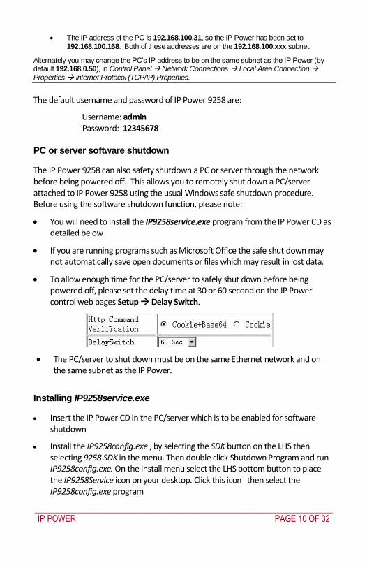
_____________________________________________________________________________
IP POWER PAGE 10 OF 32
The IP address of the PC is 19216810031 so the IP Power has been set to
192168100168 Both of these addresses are on the 192168100xxx subnet
Alternately you may change the PCrsquos IP address to be on the same subnet as the IP Power (by default 192168050) in Control Panel Network Connections Local Area Connection
Properties Internet Protocol (TCPIP) Properties
The default username and password of IP Power 9258 are
Username admin Password 12345678
PC or server software shutdown
The IP Power 9258 can also safety shutdown a PC or server through the network before being powered off This allows you to remotely shut down a PCserver attached to IP Power 9258 using the usual Windows safe shutdown procedure Before using the software shutdown function please note
You will need to install the IP9258serviceexe program from the IP Power CD as detailed below
If you are running programs such as Microsoft Office the safe shut down may not automatically save open documents or files which may result in lost data
To allow enough time for the PCserver to safely shut down before being powered off please set the delay time at 30 or 60 second on the IP Power control web pages Setup Delay Switch
The PCserver to shut down must be on the same Ethernet network and on the same subnet as the IP Power
Installing IP9258serviceexe
Insert the IP Power CD in the PCserver which is to be enabled for software shutdown
Install the IP9258configexe by selecting the SDK button on the LHS then selecting 9258 SDK in the menu Then double click Shutdown Program and run IP9258configexe On the install menu select the LHS bottom button to place the IP9258Service icon on your desktop Click this icon then select the IP9258configexe program
_____________________________________________________________________________
IP POWER PAGE 11 OF 32
Fill in the fields as follows
IP9258 Address The IP Powerrsquos IP address
HTTP Port The port of the IP Power control web pages ndash this will be 80 unless you have changed it
Username admin
Password The IP Power admin password (default 12345678)
Power Number The OUT power outlet the PCserver is connected through ndash if many PCservers are connected through the one power outlet and are registered with the same IP Power unit they will all be shutdown at the same time
Click Save Change Install Service then Start Service Restart the PCserver then
it will be enabled for software shutdown
5 IP Power Control Using Browser
To access the IP Power control web pages simply type the IP address of the IP Power into your web browserrsquos address field
_____________________________________________________________________________
IP POWER PAGE 12 OF 32
The username is admin and the default password is 12345678 Enter these credentials or the password you have set Click OK to enter the IP Power control web pages
Control the power supply by outlet
IP Power 9258 can control 4 outputs individually or at the same time
Select the Set Power from the left hand menu
You can choose to power off and power on an outlet You may also set the
time to delay before performing the chosen action under Timer by entering the time to delay in seconds and selecting On
Querying the power state of the outlets
Click Set Power again to refresh the status The state of each power outlet is displayed under the Control column
_____________________________________________________________________________
IP POWER PAGE 13 OF 32
System settings with browser
You may set the password IP address e-mail address timer setting perform an online firmware update and set the time of the IP Power through the IP Power control web pages
Setting the password for IP Power
Select Change password from the left hand menu The default password 12345678 You may change it to a password of your choosing (no longer than 8 characters) Click Apply to save the change
NOTE
If you lose or forget the admin password enter the username super user at the log in webpage
and then click OK Then turn the power off for a few seconds before turning the power back on The IP Power will to be reset to using the default password of 12345678 Note There is space between super and user
Setting the IP Powerrsquos IP address
Select Setup from the left hand menu Fill in the new IP Address Subnet Mask Default Gateway and DNS server address If your network has a DHCP server automatically allocating network settings you may choose to enable the IP Powerrsquos DHP Client The Beeper sound may also be enabled or disabled on this page
_____________________________________________________________________________
IP POWER PAGE 14 OF 32
If the IP Power is connected to your Local Area Network (LAN)
You may set a fixed IP address or have it automatically assigned by a DHCP server It is suggested that you use a fixed IP address so that it is always known After changing the IP Powerrsquos IP address type the new address in the address field of your web browser You can also use the ipEditexe tool to locate the IP Power
If the IP Power is connected to the Internet (WAN)
IP Address Enter the IP address provided by your ISP If IP Power is working with a router please refer to the network settings of the router The IP address format is xxxxxxxxxxxx yyyyy where yyyyy means the port number ranging from 1 to 32767
Subnet Mask Enter the Subnet Mask provided by your ISP If the IP Power is working with a router please refer to the network settings of the router Subnet Mask from 0 to 254 ( xxxxxxxxx0 ~ xxxxxxxxx254)
Default gateway Enter the Default Gateway provided by your ISP If the IP Power is working with a router please refer to the network settings of the router
DNS Server Enter the IP address of the DNS server provided by your ISP
DHCP Client Automatically obtain network settings from your ISP
If DHCP is disabled you must set the TCP port and default gateway If DHCP is enabled then the TCP port is preset to 80 (xxxxxxxxxxxx80) and the default gateway will be assigned by the DHCP server
If you specify a TCP port other than 80 enter it after the IP address of the IP Power when accessing the IP Power control web pages eg httpxxxxxxxxxxxxyyyyy
Beeper Setting Enable ndash activate the beeper sounds Disable ndash turn off beep
sounds When controlling the IP Power through the web pages the beeper if enabled beeps once to indicate an action has been successful
HTTP Command Verification specifies the HTTP authentication for the IP Power to use
_____________________________________________________________________________
IP POWER PAGE 15 OF 32
o Cookie +Base64 (allows HTTP command amp SDK control) o Cookie (allows HTTP command amp SDK control)
Email settings
The IP Power can be set to email its IP address to multiple recipients
Mail Server The SMTP server for sending email Please ensure that it is available
POP3Server Incoming Mail Server Enter IP address from your ISP for sending Internet IP address by E-mail
Username The SMTP username for sending email
Password The password for Usernamersquos account Note the password can be no longer than 8 characters
Sender The same of the sender to use This will often be usernameyourdomain
Receiver 1 ndash 3 The email addresses to receive the IP Powerrsquos IP address They will receive an email containing the IP Powerrsquos IP address each time your log in to the IP Power control web pages Each receiver may be no more than 50 characters
Subject The subject of the mail no more than 50 characters
Mail Body Type the content of the mail here It must not be left blank
_____________________________________________________________________________
IP POWER PAGE 16 OF 32
Click Save to save your settings
Power control using the time schedule
The IP Power can be set to power on or off power outlets at specified times Select Power Schedule from the left hand menu
Each power outlet has two rows one for the start of the schedule (eg powering an outlet on) and one for the end of the schedule (eg powering the outlet off two hours later) Additionally the Parameter column determines how regularly the schedule should be applied
Disable
Just Once
Every day
Work days every Monday to Friday
Weekend every Saturday and Sunday
Default outlet settings
When the IP Power is powered on each outlet will have power applied according to the default outlet settings In the example below all power outlets default to OFF when the IP Power is initially powered on
_____________________________________________________________________________
IP POWER PAGE 17 OF 32
Clock settings amp network time protocol (NTP)
You may manually set the IP Powerrsquos internal clock by specifying the year month day hour minutes and seconds
Alternately you may choose to synchronize with an NTP server by entering its IP address and your numeric Time Zone (relative to UTC) If your network or ISP doesnrsquot have an NTP server lists of public NTP servers are available on the web
Wake on LAN (WOL)
Through its network port the IP Power can send a Wake on LAN packet to a shutdown or hibernating PC on your network causing it to power up This facility presumes
1 The PCrsquos motherboard must support the WOL function and it must be enabled in the BIOS (typically under Power Management) The PC must be connected to the same Ethernet network as the IP Power via its network port
2 The PCrsquos network cardrsquos WOL connector must be connected to the motherboard or the network port must be integrated into the motherboard
After setting up the motherboard and network card use the WOL function by following two steps
Go to Network Wakeup on the IP Power control web pages
Enter the MAC address (the network cardrsquos physical address) of the PC and click Send ndash the PC will be powered on
_____________________________________________________________________________
IP POWER PAGE 18 OF 32
NOTE
To find out your network cardrsquos MAC address
Right click on the network connection icon Status Support Details The value in Physical Address is the MAC address
6 Firmware Update
Warning If you have not been advised to update the IP Powerrsquos firmware and do not have a new firmware file please do not go to this page
NOTE Before updating the IP Powerrsquos firmware ensure the IP Power control web pagesrsquo TCP port is set
to 80 (this is the default) otherwise the update may fail
Firmware updates are periodically released to update the functionality of the IP Power To update the IP Powerrsquos firmware select Firmware Update from the left hand menu
The following warning is displayed
_____________________________________________________________________________
IP POWER PAGE 19 OF 32
Warning Do not click Update if you do not have a firmware update file
Click Update the following window is displayed
Click Browse and locate the firmware update file Click Update to begin the update
Note When the update is complete you must wait at least one minute before you restart the IP Power
7 DDNS Settings
When connecting to the Internet the IP address you gain from ISP may be dynamically allocated so it may change each time the Internet connection reconnects This may result in the IP Power becoming uncontactable to remote clients as the new address is unknown Dynamic DNS addresses this issue by updating DNS records whenever the IP address changes The IP Power can utilize the free service provided by DynDNS (httpwwwdyndnscom) for this purpose The IP Power will always be contactable using its DynDNS address (eg ippowerdyndnsorg) regardless of its IP address
_____________________________________________________________________________
IP POWER PAGE 20 OF 32
First create a DynDNS account and create an account Create a dynamic DNS host for the IP Power eg ippowerdyndnsorg On the IP Power select DDNS from the left hand menu Enter the IP address and port of the DynDNS server You can find this out on your PC by selecting Start Run then type in cmd and typing ping wwwdyndnscom Enter the number in brackets (eg 6320819666) followed by 80 to denote the port In Your Domain enter the IP Powerrsquos DynDNS address eg ippowerdyndnsorg Enter the Username and Password for the DynDNS account you created Ensure Enable DDNS is set to TRUE Click Save Now each time the IP Power is powered on or Update Now is clicked the DynDNS address will be updated to the IP Powerrsquos current IP address Note that the change may take several minutes to propagate to your local DNS server If the IP Power cannot reach the DynDNS server without going through a proxy server select TRUE next to Proxy Enable Enter the IP address of the proxy server in Proxy IP and the port in Proxy Port
NOTE
The first time you configure DDNS click Update Now to set the DynDNS address
8 Control Using Telnet HTTP amp SNMP Commands
The IP Power is a principally a browser controlled unit with power control effected over the LAN using HTTP commands or a browser However it also provides alternate methods for directly setting and getting the status of the power outlets through Telnet commands and HTTP commands (which may be useful for controlling the IP Powerrsquos outlets using an automated script) and through SMNP Power outlet status and control using HTTP commands
The format of the HTTP command is
_____________________________________________________________________________
IP POWER PAGE 21 OF 32
httpusernamepasswordabcdSetcmdCMD=command+outlet_id=10+out
let_id=10 Where username The username you use to login to the IP Power (default is admin)
password The password you use to login to the IP Power (default is 12345678)
abcd The IP address of the IP Power (default is 192168050)
command GetPower to read the status (specifying outlets is not required) SetPower to turn on or off the ports (power setting for each outlet must
be specified after the command)
port_id (SetPower only) P60 Port 1 P61 Port 2 P62 Port 3 P63 Port 4 Example 1 The HTTP command httpadmin123456781921680 50SetcmdCMD=GetPower Returns the power status for each outlet in the following format (outlets 5 to 8 may be ignored) lthtmlgtP60=0P61=0P62=0P63=0P64=0P65=0P66=0P67=0lthtmlgt In the above example all outlets are off Example 2 The HTTP command httpadmin12345678192168050SetcmdCMD=SetPower+P60=1+P61=0+P62=0+P63=1
_____________________________________________________________________________
IP POWER PAGE 22 OF 32
Turns the power on for the first (P60) and fourth (P63) outlets and turns power off for the second (P61) and third (P62) outlets Returns the power status for each outlet in the following format lthtmlgtP60=1P61=0P62=0P63=1lthtmlgt Example 3 The HTTP command to control the 9258 operation at a specified time httpusernamepasswordXXXXXXXXXXXXSetcmdCMD=SetSchedule+Power =+YY=+MM=+DD=+HH=+MN=+SS=+PARAM=+ONOFF= Where Control parameters are 1A 1B 2A 2B 3A 3B 4A 4B A = connect power B = disconnect power YY=+MM=+DD=+HH=+MN=+SS= time parameter YY year (20YY) 01 = 2001 MM month (0 1-12) DD date (01-31) HH hour (24 hours 0- 23) MN minute (1-60) SS second (1-60) PARAM= time schedule parameter Parameter list as follows 128 Once only 127 Every day 31 Week days (Monday to Friday) 96 Weekend days (Saturday and Sunday) ONOFF= operate parameter 0 open 1 close For example
_____________________________________________________________________________
IP POWER PAGE 23 OF 32
http admin12345678192168110SetcmdCMD=SetSchedule+Power=1A+YY=2009+MM=02+DD=16+HH=06+MN=02+SS=16+PARAM=128+ONOFF=1 The above command controls the IP Power at IP address 19216810 user name is admin and password is 12345678 This 9258 will connect power of outlet 1 (p60) once only on 16th February 2009 at 602 am
NOTE Use + to separate each parameter eg to simply power on outlet 1 httpadmin12345678192168110SetcmdCMD=SetPower+P60=1
The command syntax is case sensitive so be selective when using upper and lower case in command format The free tool wget is useful for sending these HTTP commands For example
to send the command in Example 1 you could use wget ndashO -httpadmin12345678192168050SetcmdCMD=SetPower+P60=1+P61=0+P62=0+P63=1
Power outlet status and control using Telnet
Under DOS mode type ldquo Cgttelnet [IP9258] ldquo
To log in to the device use the syntax login=password
Typing help will give you the other commands that are available for the 9258 in telnet
_____________________________________________________________________________
IP POWER PAGE 24 OF 32
The getpower command reports the status of power outlets 1-4 The setpower command controls the power outlets 1-4 with ldquo0rdquo turning power off and ldquo1rdquo turning power on Example 1 setpower =11110000 (This will turn on power 1-4) Example 2 setpower =11000000 (This turns on power on 1 amp 2 and turns off power 3 amp 4)
NOTE Only the first four numbers are used You can select from 0 to turn off the power to 1 to turn on the
power However with 155 the syntax requires to use eight separte digits If you only use four digits the command will not work properly
_____________________________________________________________________________
IP POWER PAGE 25 OF 32
Power outlet status and control using SNMP
Reading status
snmpget -v 1 -c public 192168155 1361419258210 (read status of Power1)
snmpget -v 1 -c public 192168155 1361419258220 (read status of Power2) snmpget -v 1 -c public 192168155 1361419258230 (read status of Power3) snmpget -v 1 -c public 192168155 1361419258240 (read status of Power4)
(Return value as ldquoINTEGER 1 rdquo means power ON Return value as ldquoINTEGER 0 rdquo means power OFF)
_____________________________________________________________________________
IP POWER PAGE 26 OF 32
Control outlet command
snmpset -v 1 -c public 192168155 1361419258210 integer 1 (turn on Power1) snmpset -v 1 -c public 192168155 1361419258220 integer 0 (turn off Power2)
snmpset -v 1 -c public 192168155 1361419258230 integer 1 (turn on Power3) snmpset -v 1 -c public 192168155 1361419258240 integer 0 (turn off Power4)
Power cycle outlet command snmpset -v 1 -c public 192168155 1361419258310 integer 1 (powercycle No1)
snmpset -v 1 -c public 192168155 1361419258320 integer 1 (powercycle No2) snmpset -v 1 -c public 192168155 1361419258330 integer 1 (powercycle No3)
_____________________________________________________________________________
IP POWER PAGE 27 OF 32
snmpset -v 1 -c public 192168155 1361419258340 integer 1 (powercycle No4)
If the power is on the outlet will turn ldquoOFF to ON ldquo when the power cycle command is placed However if powered off the outlet will turn ldquoON to OFF to ON ldquo when place power cycle command
9 Frequently Asked Question
Q1 I forgot the password and can not enter the administration page now what can I do A1 Use the username super user when logging in to the webpage and then click OK Turn the IP Power off for a few seconds the turn it back on The default username of admin and password of 12345678 will be restored Note there is a space between super and user
10 Manual Control Mode
The IP Power is generally controlled from a local or remote computer however the outlets can also be controlled manually
NOTE
Before using the manual control function it is necessary to UNPLUG DISCONNECT all of the 4 outlets
To obtain manual control
_____________________________________________________________________________
IP POWER PAGE 28 OF 32
Press and hold the ONOFF button (depicted below) for a full 5 seconds or until a sustained beep noise is heard ndash this enables manual control mode which can be identified by the flashing outlet lights
The outlet light that is not flashing is the one currently under manual control ndash this outlet can be turned on or off by pressing the ONOFF button
To select an alternate outlet to control press the Cycle button (labeled with a circle with arrows on it)
To disable manual control mode press and hold the ONOFF button for 5 seconds or until you can hear a sustained beep noise ndash signifying the deactivation of manual control mode
Cycle (left) Select power outlet to manually control
ONOFF (right) Press and hold to enabledisable manual control mode press to turn onoff the outlet selected by the cycle button
11 IP Power Control Using Console Server
The IP Power 9258 is a simple browser controlled power switch without the security features needed for open public network connection Nor does it have any remote out-of-band dial-in support
However the IP Power can be configured securely and its outlets can be controlled in-band and out of band when used in conjunction with an Opengear console server
Out of band access
The Opengear console server provides secure remoteout-of-band access through a dial in modem (or through an alternate broadband connection) To configure the console server for dial-in access
_____________________________________________________________________________
IP POWER PAGE 29 OF 32
Connect a modem to the consolemodem port and configure the console server for dial-in
The IP Power can then be network or serially connected to the console server
SSH tunneled control through the Console Server
If the IP Power is connected on the remote LAN with the console server then it can be browser controlled
Configure the console server with the IP Power as a HTTP accessible Host This Managed Device can then be remotely controlled securely using SSH tunneling (SDT)
Configure the remote SDTConnector client to access the gateway (console server) and then to connect to the IP Power using HTTP (refer wwwopengearcomfaq267html for details)
Console Server serial control
The IP Power is a principally a browser controlled unit and its RS232 serial port mainly provides diagnostic and status information (eg sending out its IP address and power on messages during Power On Self Test) However the IP Power serial port also supports emergency power control To configure the IP Power for serial control
Connect the IP Power 9258s CONSOLE RS232 port to one of the console server serial ports (for CM4001 2 this interconnection will use a standard UTP Cat 5 cable with a 319000 adapter at each end and all other console servers will only require one 319000 adaptor)
Configured the console server serial port with a serially controlled PDU
_____________________________________________________________________________
IP POWER PAGE 30 OF 32
The IP Power outlets are then controlled by securely (HTTPS) accessing the Manage Power menu on the console server Management Console (refer wwwopengearcomfaq231html for details)
NOTE
The outlet control commands are sent from the console server to the IP Power over the serial port
The combination of out of band access and IP Power serial port control can be particularly useful in managing remote sites where a DSL router (interconnect the office LAN and the internet) may have become dysfunctional requiring a power reset
12 General IP Power Control Using Serial Port
The IP Power RS232 serial port mainly provides diagnostic and status information however the serial port can be used for emergency power control as covered in the previous section
Usage power-ip9258 ltportgt ltoutletgt [outlet] on|off|status
The serial control script below is used in the console server and should work on a normal Linux box
binsh
out_udelay=50000
_____________________________________________________________________________
IP POWER PAGE 31 OF 32
out_retries=3
in_udelay=100000
in_retries=10
port=$1
outlets=$2 cmd=$3 tmpfile=tmptmp$$
if [[ -z $port ]] || [[ -z $outlets ]] || [[ -z $cmd ]] then appname=`basename $0`
echo Usage $appname ltportgt ltoutletgt [outlet] on|off|status exit 1 fi
function ipp_chat () out=$1
in=$2 cat $port gt $tmpfile amp
cat_pid=$ trap rm $tmpfile kill $cat_pid EXIT
for (( i=0 i lt $out_retries i++ )) do for (( j = 0 j lt $out j++ )) do usleep $out_udelay
echo -n $out$j1 gt $port done echo gt $port
for (( j=0 j lt $in_retries j++ )) do usleep $in_udelay line=`grep $in $tmpfile`
if [[ -n $line ]] then break 2 fi
done done
rm $tmpfile kill $cat_pid
if [[ -n $line ]] then echo $line else
echo Command failed ($out) exit 1 fi
Suppress error messages from the shell
exec 2gt devnull Set up the serial port for the IP Power
_____________________________________________________________________________
IP POWER PAGE 32 OF 32
stty 14004cbea3031c7f15401011131a012f17160000000000000
000 lt $port Enable serial command mode
ipp_chat 0ADEBUG9258Z IP9258 DEBUG ON ampgt devnull Get current status
status_nibble=`ipp_chat 0Ap06Z p6 | sed sp6()1g`
Send the command the least significant bit is port 1 the most significant is port 4 A value of 0 is on 1 is off
outlet_mask=0 for o in $outlets do outlet_bit=$(( 1ltlt $o-1 ))
outlet_mask=$(( outlet_mask | $outlet_bit )) done status_nibble=`printf d 0x$status_nibble`
if [[ $cmd == on ]] then echo Powering on outlet $outlets status_nibble=`printf X $(( $status_nibble amp ~$outlet_mask ))`
ipp_chat 0AP06F$status_nibbleZ P6=F$status_nibble ampgt devnull echo Outlet $outlets powered on
elif [[ $cmd == off ]] then echo Powering off outlet $outlets status_nibble=`printf X $(( $status_nibble | $outlet_mask ))`
ipp_chat 0AP06F$status_nibbleZ P6=F$status_nibble ampgt devnull echo Outlet $outlets powered off
else for o in $outlets do outlet_bit=$(( 1ltlt $o-1 ))
echo -n Outlet $o is if [[ $(( $status_nibble amp $outlet_bit )) -eq $outlet_bit ]] then echo off
else echo on fi
done fi
Disable serial command mode ipp_chat 0ADEBUG0FFZ IP9258 DEBUG OFF ampgt devnull exit 0
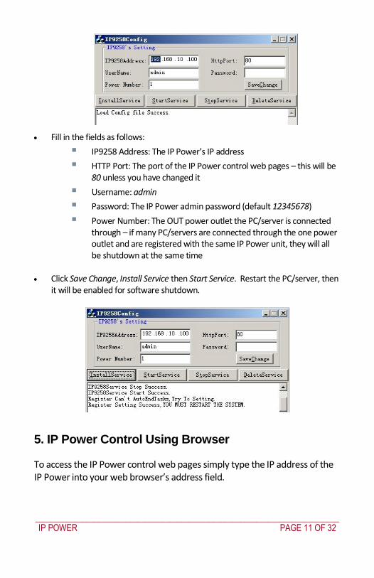
_____________________________________________________________________________
IP POWER PAGE 11 OF 32
Fill in the fields as follows
IP9258 Address The IP Powerrsquos IP address
HTTP Port The port of the IP Power control web pages ndash this will be 80 unless you have changed it
Username admin
Password The IP Power admin password (default 12345678)
Power Number The OUT power outlet the PCserver is connected through ndash if many PCservers are connected through the one power outlet and are registered with the same IP Power unit they will all be shutdown at the same time
Click Save Change Install Service then Start Service Restart the PCserver then
it will be enabled for software shutdown
5 IP Power Control Using Browser
To access the IP Power control web pages simply type the IP address of the IP Power into your web browserrsquos address field
_____________________________________________________________________________
IP POWER PAGE 12 OF 32
The username is admin and the default password is 12345678 Enter these credentials or the password you have set Click OK to enter the IP Power control web pages
Control the power supply by outlet
IP Power 9258 can control 4 outputs individually or at the same time
Select the Set Power from the left hand menu
You can choose to power off and power on an outlet You may also set the
time to delay before performing the chosen action under Timer by entering the time to delay in seconds and selecting On
Querying the power state of the outlets
Click Set Power again to refresh the status The state of each power outlet is displayed under the Control column
_____________________________________________________________________________
IP POWER PAGE 13 OF 32
System settings with browser
You may set the password IP address e-mail address timer setting perform an online firmware update and set the time of the IP Power through the IP Power control web pages
Setting the password for IP Power
Select Change password from the left hand menu The default password 12345678 You may change it to a password of your choosing (no longer than 8 characters) Click Apply to save the change
NOTE
If you lose or forget the admin password enter the username super user at the log in webpage
and then click OK Then turn the power off for a few seconds before turning the power back on The IP Power will to be reset to using the default password of 12345678 Note There is space between super and user
Setting the IP Powerrsquos IP address
Select Setup from the left hand menu Fill in the new IP Address Subnet Mask Default Gateway and DNS server address If your network has a DHCP server automatically allocating network settings you may choose to enable the IP Powerrsquos DHP Client The Beeper sound may also be enabled or disabled on this page
_____________________________________________________________________________
IP POWER PAGE 14 OF 32
If the IP Power is connected to your Local Area Network (LAN)
You may set a fixed IP address or have it automatically assigned by a DHCP server It is suggested that you use a fixed IP address so that it is always known After changing the IP Powerrsquos IP address type the new address in the address field of your web browser You can also use the ipEditexe tool to locate the IP Power
If the IP Power is connected to the Internet (WAN)
IP Address Enter the IP address provided by your ISP If IP Power is working with a router please refer to the network settings of the router The IP address format is xxxxxxxxxxxx yyyyy where yyyyy means the port number ranging from 1 to 32767
Subnet Mask Enter the Subnet Mask provided by your ISP If the IP Power is working with a router please refer to the network settings of the router Subnet Mask from 0 to 254 ( xxxxxxxxx0 ~ xxxxxxxxx254)
Default gateway Enter the Default Gateway provided by your ISP If the IP Power is working with a router please refer to the network settings of the router
DNS Server Enter the IP address of the DNS server provided by your ISP
DHCP Client Automatically obtain network settings from your ISP
If DHCP is disabled you must set the TCP port and default gateway If DHCP is enabled then the TCP port is preset to 80 (xxxxxxxxxxxx80) and the default gateway will be assigned by the DHCP server
If you specify a TCP port other than 80 enter it after the IP address of the IP Power when accessing the IP Power control web pages eg httpxxxxxxxxxxxxyyyyy
Beeper Setting Enable ndash activate the beeper sounds Disable ndash turn off beep
sounds When controlling the IP Power through the web pages the beeper if enabled beeps once to indicate an action has been successful
HTTP Command Verification specifies the HTTP authentication for the IP Power to use
_____________________________________________________________________________
IP POWER PAGE 15 OF 32
o Cookie +Base64 (allows HTTP command amp SDK control) o Cookie (allows HTTP command amp SDK control)
Email settings
The IP Power can be set to email its IP address to multiple recipients
Mail Server The SMTP server for sending email Please ensure that it is available
POP3Server Incoming Mail Server Enter IP address from your ISP for sending Internet IP address by E-mail
Username The SMTP username for sending email
Password The password for Usernamersquos account Note the password can be no longer than 8 characters
Sender The same of the sender to use This will often be usernameyourdomain
Receiver 1 ndash 3 The email addresses to receive the IP Powerrsquos IP address They will receive an email containing the IP Powerrsquos IP address each time your log in to the IP Power control web pages Each receiver may be no more than 50 characters
Subject The subject of the mail no more than 50 characters
Mail Body Type the content of the mail here It must not be left blank
_____________________________________________________________________________
IP POWER PAGE 16 OF 32
Click Save to save your settings
Power control using the time schedule
The IP Power can be set to power on or off power outlets at specified times Select Power Schedule from the left hand menu
Each power outlet has two rows one for the start of the schedule (eg powering an outlet on) and one for the end of the schedule (eg powering the outlet off two hours later) Additionally the Parameter column determines how regularly the schedule should be applied
Disable
Just Once
Every day
Work days every Monday to Friday
Weekend every Saturday and Sunday
Default outlet settings
When the IP Power is powered on each outlet will have power applied according to the default outlet settings In the example below all power outlets default to OFF when the IP Power is initially powered on
_____________________________________________________________________________
IP POWER PAGE 17 OF 32
Clock settings amp network time protocol (NTP)
You may manually set the IP Powerrsquos internal clock by specifying the year month day hour minutes and seconds
Alternately you may choose to synchronize with an NTP server by entering its IP address and your numeric Time Zone (relative to UTC) If your network or ISP doesnrsquot have an NTP server lists of public NTP servers are available on the web
Wake on LAN (WOL)
Through its network port the IP Power can send a Wake on LAN packet to a shutdown or hibernating PC on your network causing it to power up This facility presumes
1 The PCrsquos motherboard must support the WOL function and it must be enabled in the BIOS (typically under Power Management) The PC must be connected to the same Ethernet network as the IP Power via its network port
2 The PCrsquos network cardrsquos WOL connector must be connected to the motherboard or the network port must be integrated into the motherboard
After setting up the motherboard and network card use the WOL function by following two steps
Go to Network Wakeup on the IP Power control web pages
Enter the MAC address (the network cardrsquos physical address) of the PC and click Send ndash the PC will be powered on
_____________________________________________________________________________
IP POWER PAGE 18 OF 32
NOTE
To find out your network cardrsquos MAC address
Right click on the network connection icon Status Support Details The value in Physical Address is the MAC address
6 Firmware Update
Warning If you have not been advised to update the IP Powerrsquos firmware and do not have a new firmware file please do not go to this page
NOTE Before updating the IP Powerrsquos firmware ensure the IP Power control web pagesrsquo TCP port is set
to 80 (this is the default) otherwise the update may fail
Firmware updates are periodically released to update the functionality of the IP Power To update the IP Powerrsquos firmware select Firmware Update from the left hand menu
The following warning is displayed
_____________________________________________________________________________
IP POWER PAGE 19 OF 32
Warning Do not click Update if you do not have a firmware update file
Click Update the following window is displayed
Click Browse and locate the firmware update file Click Update to begin the update
Note When the update is complete you must wait at least one minute before you restart the IP Power
7 DDNS Settings
When connecting to the Internet the IP address you gain from ISP may be dynamically allocated so it may change each time the Internet connection reconnects This may result in the IP Power becoming uncontactable to remote clients as the new address is unknown Dynamic DNS addresses this issue by updating DNS records whenever the IP address changes The IP Power can utilize the free service provided by DynDNS (httpwwwdyndnscom) for this purpose The IP Power will always be contactable using its DynDNS address (eg ippowerdyndnsorg) regardless of its IP address
_____________________________________________________________________________
IP POWER PAGE 20 OF 32
First create a DynDNS account and create an account Create a dynamic DNS host for the IP Power eg ippowerdyndnsorg On the IP Power select DDNS from the left hand menu Enter the IP address and port of the DynDNS server You can find this out on your PC by selecting Start Run then type in cmd and typing ping wwwdyndnscom Enter the number in brackets (eg 6320819666) followed by 80 to denote the port In Your Domain enter the IP Powerrsquos DynDNS address eg ippowerdyndnsorg Enter the Username and Password for the DynDNS account you created Ensure Enable DDNS is set to TRUE Click Save Now each time the IP Power is powered on or Update Now is clicked the DynDNS address will be updated to the IP Powerrsquos current IP address Note that the change may take several minutes to propagate to your local DNS server If the IP Power cannot reach the DynDNS server without going through a proxy server select TRUE next to Proxy Enable Enter the IP address of the proxy server in Proxy IP and the port in Proxy Port
NOTE
The first time you configure DDNS click Update Now to set the DynDNS address
8 Control Using Telnet HTTP amp SNMP Commands
The IP Power is a principally a browser controlled unit with power control effected over the LAN using HTTP commands or a browser However it also provides alternate methods for directly setting and getting the status of the power outlets through Telnet commands and HTTP commands (which may be useful for controlling the IP Powerrsquos outlets using an automated script) and through SMNP Power outlet status and control using HTTP commands
The format of the HTTP command is
_____________________________________________________________________________
IP POWER PAGE 21 OF 32
httpusernamepasswordabcdSetcmdCMD=command+outlet_id=10+out
let_id=10 Where username The username you use to login to the IP Power (default is admin)
password The password you use to login to the IP Power (default is 12345678)
abcd The IP address of the IP Power (default is 192168050)
command GetPower to read the status (specifying outlets is not required) SetPower to turn on or off the ports (power setting for each outlet must
be specified after the command)
port_id (SetPower only) P60 Port 1 P61 Port 2 P62 Port 3 P63 Port 4 Example 1 The HTTP command httpadmin123456781921680 50SetcmdCMD=GetPower Returns the power status for each outlet in the following format (outlets 5 to 8 may be ignored) lthtmlgtP60=0P61=0P62=0P63=0P64=0P65=0P66=0P67=0lthtmlgt In the above example all outlets are off Example 2 The HTTP command httpadmin12345678192168050SetcmdCMD=SetPower+P60=1+P61=0+P62=0+P63=1
_____________________________________________________________________________
IP POWER PAGE 22 OF 32
Turns the power on for the first (P60) and fourth (P63) outlets and turns power off for the second (P61) and third (P62) outlets Returns the power status for each outlet in the following format lthtmlgtP60=1P61=0P62=0P63=1lthtmlgt Example 3 The HTTP command to control the 9258 operation at a specified time httpusernamepasswordXXXXXXXXXXXXSetcmdCMD=SetSchedule+Power =+YY=+MM=+DD=+HH=+MN=+SS=+PARAM=+ONOFF= Where Control parameters are 1A 1B 2A 2B 3A 3B 4A 4B A = connect power B = disconnect power YY=+MM=+DD=+HH=+MN=+SS= time parameter YY year (20YY) 01 = 2001 MM month (0 1-12) DD date (01-31) HH hour (24 hours 0- 23) MN minute (1-60) SS second (1-60) PARAM= time schedule parameter Parameter list as follows 128 Once only 127 Every day 31 Week days (Monday to Friday) 96 Weekend days (Saturday and Sunday) ONOFF= operate parameter 0 open 1 close For example
_____________________________________________________________________________
IP POWER PAGE 23 OF 32
http admin12345678192168110SetcmdCMD=SetSchedule+Power=1A+YY=2009+MM=02+DD=16+HH=06+MN=02+SS=16+PARAM=128+ONOFF=1 The above command controls the IP Power at IP address 19216810 user name is admin and password is 12345678 This 9258 will connect power of outlet 1 (p60) once only on 16th February 2009 at 602 am
NOTE Use + to separate each parameter eg to simply power on outlet 1 httpadmin12345678192168110SetcmdCMD=SetPower+P60=1
The command syntax is case sensitive so be selective when using upper and lower case in command format The free tool wget is useful for sending these HTTP commands For example
to send the command in Example 1 you could use wget ndashO -httpadmin12345678192168050SetcmdCMD=SetPower+P60=1+P61=0+P62=0+P63=1
Power outlet status and control using Telnet
Under DOS mode type ldquo Cgttelnet [IP9258] ldquo
To log in to the device use the syntax login=password
Typing help will give you the other commands that are available for the 9258 in telnet
_____________________________________________________________________________
IP POWER PAGE 24 OF 32
The getpower command reports the status of power outlets 1-4 The setpower command controls the power outlets 1-4 with ldquo0rdquo turning power off and ldquo1rdquo turning power on Example 1 setpower =11110000 (This will turn on power 1-4) Example 2 setpower =11000000 (This turns on power on 1 amp 2 and turns off power 3 amp 4)
NOTE Only the first four numbers are used You can select from 0 to turn off the power to 1 to turn on the
power However with 155 the syntax requires to use eight separte digits If you only use four digits the command will not work properly
_____________________________________________________________________________
IP POWER PAGE 25 OF 32
Power outlet status and control using SNMP
Reading status
snmpget -v 1 -c public 192168155 1361419258210 (read status of Power1)
snmpget -v 1 -c public 192168155 1361419258220 (read status of Power2) snmpget -v 1 -c public 192168155 1361419258230 (read status of Power3) snmpget -v 1 -c public 192168155 1361419258240 (read status of Power4)
(Return value as ldquoINTEGER 1 rdquo means power ON Return value as ldquoINTEGER 0 rdquo means power OFF)
_____________________________________________________________________________
IP POWER PAGE 26 OF 32
Control outlet command
snmpset -v 1 -c public 192168155 1361419258210 integer 1 (turn on Power1) snmpset -v 1 -c public 192168155 1361419258220 integer 0 (turn off Power2)
snmpset -v 1 -c public 192168155 1361419258230 integer 1 (turn on Power3) snmpset -v 1 -c public 192168155 1361419258240 integer 0 (turn off Power4)
Power cycle outlet command snmpset -v 1 -c public 192168155 1361419258310 integer 1 (powercycle No1)
snmpset -v 1 -c public 192168155 1361419258320 integer 1 (powercycle No2) snmpset -v 1 -c public 192168155 1361419258330 integer 1 (powercycle No3)
_____________________________________________________________________________
IP POWER PAGE 27 OF 32
snmpset -v 1 -c public 192168155 1361419258340 integer 1 (powercycle No4)
If the power is on the outlet will turn ldquoOFF to ON ldquo when the power cycle command is placed However if powered off the outlet will turn ldquoON to OFF to ON ldquo when place power cycle command
9 Frequently Asked Question
Q1 I forgot the password and can not enter the administration page now what can I do A1 Use the username super user when logging in to the webpage and then click OK Turn the IP Power off for a few seconds the turn it back on The default username of admin and password of 12345678 will be restored Note there is a space between super and user
10 Manual Control Mode
The IP Power is generally controlled from a local or remote computer however the outlets can also be controlled manually
NOTE
Before using the manual control function it is necessary to UNPLUG DISCONNECT all of the 4 outlets
To obtain manual control
_____________________________________________________________________________
IP POWER PAGE 28 OF 32
Press and hold the ONOFF button (depicted below) for a full 5 seconds or until a sustained beep noise is heard ndash this enables manual control mode which can be identified by the flashing outlet lights
The outlet light that is not flashing is the one currently under manual control ndash this outlet can be turned on or off by pressing the ONOFF button
To select an alternate outlet to control press the Cycle button (labeled with a circle with arrows on it)
To disable manual control mode press and hold the ONOFF button for 5 seconds or until you can hear a sustained beep noise ndash signifying the deactivation of manual control mode
Cycle (left) Select power outlet to manually control
ONOFF (right) Press and hold to enabledisable manual control mode press to turn onoff the outlet selected by the cycle button
11 IP Power Control Using Console Server
The IP Power 9258 is a simple browser controlled power switch without the security features needed for open public network connection Nor does it have any remote out-of-band dial-in support
However the IP Power can be configured securely and its outlets can be controlled in-band and out of band when used in conjunction with an Opengear console server
Out of band access
The Opengear console server provides secure remoteout-of-band access through a dial in modem (or through an alternate broadband connection) To configure the console server for dial-in access
_____________________________________________________________________________
IP POWER PAGE 29 OF 32
Connect a modem to the consolemodem port and configure the console server for dial-in
The IP Power can then be network or serially connected to the console server
SSH tunneled control through the Console Server
If the IP Power is connected on the remote LAN with the console server then it can be browser controlled
Configure the console server with the IP Power as a HTTP accessible Host This Managed Device can then be remotely controlled securely using SSH tunneling (SDT)
Configure the remote SDTConnector client to access the gateway (console server) and then to connect to the IP Power using HTTP (refer wwwopengearcomfaq267html for details)
Console Server serial control
The IP Power is a principally a browser controlled unit and its RS232 serial port mainly provides diagnostic and status information (eg sending out its IP address and power on messages during Power On Self Test) However the IP Power serial port also supports emergency power control To configure the IP Power for serial control
Connect the IP Power 9258s CONSOLE RS232 port to one of the console server serial ports (for CM4001 2 this interconnection will use a standard UTP Cat 5 cable with a 319000 adapter at each end and all other console servers will only require one 319000 adaptor)
Configured the console server serial port with a serially controlled PDU
_____________________________________________________________________________
IP POWER PAGE 30 OF 32
The IP Power outlets are then controlled by securely (HTTPS) accessing the Manage Power menu on the console server Management Console (refer wwwopengearcomfaq231html for details)
NOTE
The outlet control commands are sent from the console server to the IP Power over the serial port
The combination of out of band access and IP Power serial port control can be particularly useful in managing remote sites where a DSL router (interconnect the office LAN and the internet) may have become dysfunctional requiring a power reset
12 General IP Power Control Using Serial Port
The IP Power RS232 serial port mainly provides diagnostic and status information however the serial port can be used for emergency power control as covered in the previous section
Usage power-ip9258 ltportgt ltoutletgt [outlet] on|off|status
The serial control script below is used in the console server and should work on a normal Linux box
binsh
out_udelay=50000
_____________________________________________________________________________
IP POWER PAGE 31 OF 32
out_retries=3
in_udelay=100000
in_retries=10
port=$1
outlets=$2 cmd=$3 tmpfile=tmptmp$$
if [[ -z $port ]] || [[ -z $outlets ]] || [[ -z $cmd ]] then appname=`basename $0`
echo Usage $appname ltportgt ltoutletgt [outlet] on|off|status exit 1 fi
function ipp_chat () out=$1
in=$2 cat $port gt $tmpfile amp
cat_pid=$ trap rm $tmpfile kill $cat_pid EXIT
for (( i=0 i lt $out_retries i++ )) do for (( j = 0 j lt $out j++ )) do usleep $out_udelay
echo -n $out$j1 gt $port done echo gt $port
for (( j=0 j lt $in_retries j++ )) do usleep $in_udelay line=`grep $in $tmpfile`
if [[ -n $line ]] then break 2 fi
done done
rm $tmpfile kill $cat_pid
if [[ -n $line ]] then echo $line else
echo Command failed ($out) exit 1 fi
Suppress error messages from the shell
exec 2gt devnull Set up the serial port for the IP Power
_____________________________________________________________________________
IP POWER PAGE 32 OF 32
stty 14004cbea3031c7f15401011131a012f17160000000000000
000 lt $port Enable serial command mode
ipp_chat 0ADEBUG9258Z IP9258 DEBUG ON ampgt devnull Get current status
status_nibble=`ipp_chat 0Ap06Z p6 | sed sp6()1g`
Send the command the least significant bit is port 1 the most significant is port 4 A value of 0 is on 1 is off
outlet_mask=0 for o in $outlets do outlet_bit=$(( 1ltlt $o-1 ))
outlet_mask=$(( outlet_mask | $outlet_bit )) done status_nibble=`printf d 0x$status_nibble`
if [[ $cmd == on ]] then echo Powering on outlet $outlets status_nibble=`printf X $(( $status_nibble amp ~$outlet_mask ))`
ipp_chat 0AP06F$status_nibbleZ P6=F$status_nibble ampgt devnull echo Outlet $outlets powered on
elif [[ $cmd == off ]] then echo Powering off outlet $outlets status_nibble=`printf X $(( $status_nibble | $outlet_mask ))`
ipp_chat 0AP06F$status_nibbleZ P6=F$status_nibble ampgt devnull echo Outlet $outlets powered off
else for o in $outlets do outlet_bit=$(( 1ltlt $o-1 ))
echo -n Outlet $o is if [[ $(( $status_nibble amp $outlet_bit )) -eq $outlet_bit ]] then echo off
else echo on fi
done fi
Disable serial command mode ipp_chat 0ADEBUG0FFZ IP9258 DEBUG OFF ampgt devnull exit 0
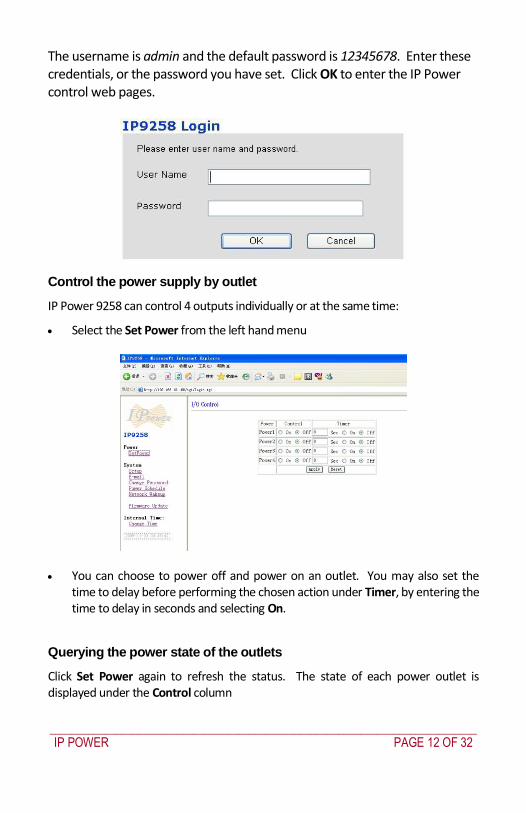
_____________________________________________________________________________
IP POWER PAGE 12 OF 32
The username is admin and the default password is 12345678 Enter these credentials or the password you have set Click OK to enter the IP Power control web pages
Control the power supply by outlet
IP Power 9258 can control 4 outputs individually or at the same time
Select the Set Power from the left hand menu
You can choose to power off and power on an outlet You may also set the
time to delay before performing the chosen action under Timer by entering the time to delay in seconds and selecting On
Querying the power state of the outlets
Click Set Power again to refresh the status The state of each power outlet is displayed under the Control column
_____________________________________________________________________________
IP POWER PAGE 13 OF 32
System settings with browser
You may set the password IP address e-mail address timer setting perform an online firmware update and set the time of the IP Power through the IP Power control web pages
Setting the password for IP Power
Select Change password from the left hand menu The default password 12345678 You may change it to a password of your choosing (no longer than 8 characters) Click Apply to save the change
NOTE
If you lose or forget the admin password enter the username super user at the log in webpage
and then click OK Then turn the power off for a few seconds before turning the power back on The IP Power will to be reset to using the default password of 12345678 Note There is space between super and user
Setting the IP Powerrsquos IP address
Select Setup from the left hand menu Fill in the new IP Address Subnet Mask Default Gateway and DNS server address If your network has a DHCP server automatically allocating network settings you may choose to enable the IP Powerrsquos DHP Client The Beeper sound may also be enabled or disabled on this page
_____________________________________________________________________________
IP POWER PAGE 14 OF 32
If the IP Power is connected to your Local Area Network (LAN)
You may set a fixed IP address or have it automatically assigned by a DHCP server It is suggested that you use a fixed IP address so that it is always known After changing the IP Powerrsquos IP address type the new address in the address field of your web browser You can also use the ipEditexe tool to locate the IP Power
If the IP Power is connected to the Internet (WAN)
IP Address Enter the IP address provided by your ISP If IP Power is working with a router please refer to the network settings of the router The IP address format is xxxxxxxxxxxx yyyyy where yyyyy means the port number ranging from 1 to 32767
Subnet Mask Enter the Subnet Mask provided by your ISP If the IP Power is working with a router please refer to the network settings of the router Subnet Mask from 0 to 254 ( xxxxxxxxx0 ~ xxxxxxxxx254)
Default gateway Enter the Default Gateway provided by your ISP If the IP Power is working with a router please refer to the network settings of the router
DNS Server Enter the IP address of the DNS server provided by your ISP
DHCP Client Automatically obtain network settings from your ISP
If DHCP is disabled you must set the TCP port and default gateway If DHCP is enabled then the TCP port is preset to 80 (xxxxxxxxxxxx80) and the default gateway will be assigned by the DHCP server
If you specify a TCP port other than 80 enter it after the IP address of the IP Power when accessing the IP Power control web pages eg httpxxxxxxxxxxxxyyyyy
Beeper Setting Enable ndash activate the beeper sounds Disable ndash turn off beep
sounds When controlling the IP Power through the web pages the beeper if enabled beeps once to indicate an action has been successful
HTTP Command Verification specifies the HTTP authentication for the IP Power to use
_____________________________________________________________________________
IP POWER PAGE 15 OF 32
o Cookie +Base64 (allows HTTP command amp SDK control) o Cookie (allows HTTP command amp SDK control)
Email settings
The IP Power can be set to email its IP address to multiple recipients
Mail Server The SMTP server for sending email Please ensure that it is available
POP3Server Incoming Mail Server Enter IP address from your ISP for sending Internet IP address by E-mail
Username The SMTP username for sending email
Password The password for Usernamersquos account Note the password can be no longer than 8 characters
Sender The same of the sender to use This will often be usernameyourdomain
Receiver 1 ndash 3 The email addresses to receive the IP Powerrsquos IP address They will receive an email containing the IP Powerrsquos IP address each time your log in to the IP Power control web pages Each receiver may be no more than 50 characters
Subject The subject of the mail no more than 50 characters
Mail Body Type the content of the mail here It must not be left blank
_____________________________________________________________________________
IP POWER PAGE 16 OF 32
Click Save to save your settings
Power control using the time schedule
The IP Power can be set to power on or off power outlets at specified times Select Power Schedule from the left hand menu
Each power outlet has two rows one for the start of the schedule (eg powering an outlet on) and one for the end of the schedule (eg powering the outlet off two hours later) Additionally the Parameter column determines how regularly the schedule should be applied
Disable
Just Once
Every day
Work days every Monday to Friday
Weekend every Saturday and Sunday
Default outlet settings
When the IP Power is powered on each outlet will have power applied according to the default outlet settings In the example below all power outlets default to OFF when the IP Power is initially powered on
_____________________________________________________________________________
IP POWER PAGE 17 OF 32
Clock settings amp network time protocol (NTP)
You may manually set the IP Powerrsquos internal clock by specifying the year month day hour minutes and seconds
Alternately you may choose to synchronize with an NTP server by entering its IP address and your numeric Time Zone (relative to UTC) If your network or ISP doesnrsquot have an NTP server lists of public NTP servers are available on the web
Wake on LAN (WOL)
Through its network port the IP Power can send a Wake on LAN packet to a shutdown or hibernating PC on your network causing it to power up This facility presumes
1 The PCrsquos motherboard must support the WOL function and it must be enabled in the BIOS (typically under Power Management) The PC must be connected to the same Ethernet network as the IP Power via its network port
2 The PCrsquos network cardrsquos WOL connector must be connected to the motherboard or the network port must be integrated into the motherboard
After setting up the motherboard and network card use the WOL function by following two steps
Go to Network Wakeup on the IP Power control web pages
Enter the MAC address (the network cardrsquos physical address) of the PC and click Send ndash the PC will be powered on
_____________________________________________________________________________
IP POWER PAGE 18 OF 32
NOTE
To find out your network cardrsquos MAC address
Right click on the network connection icon Status Support Details The value in Physical Address is the MAC address
6 Firmware Update
Warning If you have not been advised to update the IP Powerrsquos firmware and do not have a new firmware file please do not go to this page
NOTE Before updating the IP Powerrsquos firmware ensure the IP Power control web pagesrsquo TCP port is set
to 80 (this is the default) otherwise the update may fail
Firmware updates are periodically released to update the functionality of the IP Power To update the IP Powerrsquos firmware select Firmware Update from the left hand menu
The following warning is displayed
_____________________________________________________________________________
IP POWER PAGE 19 OF 32
Warning Do not click Update if you do not have a firmware update file
Click Update the following window is displayed
Click Browse and locate the firmware update file Click Update to begin the update
Note When the update is complete you must wait at least one minute before you restart the IP Power
7 DDNS Settings
When connecting to the Internet the IP address you gain from ISP may be dynamically allocated so it may change each time the Internet connection reconnects This may result in the IP Power becoming uncontactable to remote clients as the new address is unknown Dynamic DNS addresses this issue by updating DNS records whenever the IP address changes The IP Power can utilize the free service provided by DynDNS (httpwwwdyndnscom) for this purpose The IP Power will always be contactable using its DynDNS address (eg ippowerdyndnsorg) regardless of its IP address
_____________________________________________________________________________
IP POWER PAGE 20 OF 32
First create a DynDNS account and create an account Create a dynamic DNS host for the IP Power eg ippowerdyndnsorg On the IP Power select DDNS from the left hand menu Enter the IP address and port of the DynDNS server You can find this out on your PC by selecting Start Run then type in cmd and typing ping wwwdyndnscom Enter the number in brackets (eg 6320819666) followed by 80 to denote the port In Your Domain enter the IP Powerrsquos DynDNS address eg ippowerdyndnsorg Enter the Username and Password for the DynDNS account you created Ensure Enable DDNS is set to TRUE Click Save Now each time the IP Power is powered on or Update Now is clicked the DynDNS address will be updated to the IP Powerrsquos current IP address Note that the change may take several minutes to propagate to your local DNS server If the IP Power cannot reach the DynDNS server without going through a proxy server select TRUE next to Proxy Enable Enter the IP address of the proxy server in Proxy IP and the port in Proxy Port
NOTE
The first time you configure DDNS click Update Now to set the DynDNS address
8 Control Using Telnet HTTP amp SNMP Commands
The IP Power is a principally a browser controlled unit with power control effected over the LAN using HTTP commands or a browser However it also provides alternate methods for directly setting and getting the status of the power outlets through Telnet commands and HTTP commands (which may be useful for controlling the IP Powerrsquos outlets using an automated script) and through SMNP Power outlet status and control using HTTP commands
The format of the HTTP command is
_____________________________________________________________________________
IP POWER PAGE 21 OF 32
httpusernamepasswordabcdSetcmdCMD=command+outlet_id=10+out
let_id=10 Where username The username you use to login to the IP Power (default is admin)
password The password you use to login to the IP Power (default is 12345678)
abcd The IP address of the IP Power (default is 192168050)
command GetPower to read the status (specifying outlets is not required) SetPower to turn on or off the ports (power setting for each outlet must
be specified after the command)
port_id (SetPower only) P60 Port 1 P61 Port 2 P62 Port 3 P63 Port 4 Example 1 The HTTP command httpadmin123456781921680 50SetcmdCMD=GetPower Returns the power status for each outlet in the following format (outlets 5 to 8 may be ignored) lthtmlgtP60=0P61=0P62=0P63=0P64=0P65=0P66=0P67=0lthtmlgt In the above example all outlets are off Example 2 The HTTP command httpadmin12345678192168050SetcmdCMD=SetPower+P60=1+P61=0+P62=0+P63=1
_____________________________________________________________________________
IP POWER PAGE 22 OF 32
Turns the power on for the first (P60) and fourth (P63) outlets and turns power off for the second (P61) and third (P62) outlets Returns the power status for each outlet in the following format lthtmlgtP60=1P61=0P62=0P63=1lthtmlgt Example 3 The HTTP command to control the 9258 operation at a specified time httpusernamepasswordXXXXXXXXXXXXSetcmdCMD=SetSchedule+Power =+YY=+MM=+DD=+HH=+MN=+SS=+PARAM=+ONOFF= Where Control parameters are 1A 1B 2A 2B 3A 3B 4A 4B A = connect power B = disconnect power YY=+MM=+DD=+HH=+MN=+SS= time parameter YY year (20YY) 01 = 2001 MM month (0 1-12) DD date (01-31) HH hour (24 hours 0- 23) MN minute (1-60) SS second (1-60) PARAM= time schedule parameter Parameter list as follows 128 Once only 127 Every day 31 Week days (Monday to Friday) 96 Weekend days (Saturday and Sunday) ONOFF= operate parameter 0 open 1 close For example
_____________________________________________________________________________
IP POWER PAGE 23 OF 32
http admin12345678192168110SetcmdCMD=SetSchedule+Power=1A+YY=2009+MM=02+DD=16+HH=06+MN=02+SS=16+PARAM=128+ONOFF=1 The above command controls the IP Power at IP address 19216810 user name is admin and password is 12345678 This 9258 will connect power of outlet 1 (p60) once only on 16th February 2009 at 602 am
NOTE Use + to separate each parameter eg to simply power on outlet 1 httpadmin12345678192168110SetcmdCMD=SetPower+P60=1
The command syntax is case sensitive so be selective when using upper and lower case in command format The free tool wget is useful for sending these HTTP commands For example
to send the command in Example 1 you could use wget ndashO -httpadmin12345678192168050SetcmdCMD=SetPower+P60=1+P61=0+P62=0+P63=1
Power outlet status and control using Telnet
Under DOS mode type ldquo Cgttelnet [IP9258] ldquo
To log in to the device use the syntax login=password
Typing help will give you the other commands that are available for the 9258 in telnet
_____________________________________________________________________________
IP POWER PAGE 24 OF 32
The getpower command reports the status of power outlets 1-4 The setpower command controls the power outlets 1-4 with ldquo0rdquo turning power off and ldquo1rdquo turning power on Example 1 setpower =11110000 (This will turn on power 1-4) Example 2 setpower =11000000 (This turns on power on 1 amp 2 and turns off power 3 amp 4)
NOTE Only the first four numbers are used You can select from 0 to turn off the power to 1 to turn on the
power However with 155 the syntax requires to use eight separte digits If you only use four digits the command will not work properly
_____________________________________________________________________________
IP POWER PAGE 25 OF 32
Power outlet status and control using SNMP
Reading status
snmpget -v 1 -c public 192168155 1361419258210 (read status of Power1)
snmpget -v 1 -c public 192168155 1361419258220 (read status of Power2) snmpget -v 1 -c public 192168155 1361419258230 (read status of Power3) snmpget -v 1 -c public 192168155 1361419258240 (read status of Power4)
(Return value as ldquoINTEGER 1 rdquo means power ON Return value as ldquoINTEGER 0 rdquo means power OFF)
_____________________________________________________________________________
IP POWER PAGE 26 OF 32
Control outlet command
snmpset -v 1 -c public 192168155 1361419258210 integer 1 (turn on Power1) snmpset -v 1 -c public 192168155 1361419258220 integer 0 (turn off Power2)
snmpset -v 1 -c public 192168155 1361419258230 integer 1 (turn on Power3) snmpset -v 1 -c public 192168155 1361419258240 integer 0 (turn off Power4)
Power cycle outlet command snmpset -v 1 -c public 192168155 1361419258310 integer 1 (powercycle No1)
snmpset -v 1 -c public 192168155 1361419258320 integer 1 (powercycle No2) snmpset -v 1 -c public 192168155 1361419258330 integer 1 (powercycle No3)
_____________________________________________________________________________
IP POWER PAGE 27 OF 32
snmpset -v 1 -c public 192168155 1361419258340 integer 1 (powercycle No4)
If the power is on the outlet will turn ldquoOFF to ON ldquo when the power cycle command is placed However if powered off the outlet will turn ldquoON to OFF to ON ldquo when place power cycle command
9 Frequently Asked Question
Q1 I forgot the password and can not enter the administration page now what can I do A1 Use the username super user when logging in to the webpage and then click OK Turn the IP Power off for a few seconds the turn it back on The default username of admin and password of 12345678 will be restored Note there is a space between super and user
10 Manual Control Mode
The IP Power is generally controlled from a local or remote computer however the outlets can also be controlled manually
NOTE
Before using the manual control function it is necessary to UNPLUG DISCONNECT all of the 4 outlets
To obtain manual control
_____________________________________________________________________________
IP POWER PAGE 28 OF 32
Press and hold the ONOFF button (depicted below) for a full 5 seconds or until a sustained beep noise is heard ndash this enables manual control mode which can be identified by the flashing outlet lights
The outlet light that is not flashing is the one currently under manual control ndash this outlet can be turned on or off by pressing the ONOFF button
To select an alternate outlet to control press the Cycle button (labeled with a circle with arrows on it)
To disable manual control mode press and hold the ONOFF button for 5 seconds or until you can hear a sustained beep noise ndash signifying the deactivation of manual control mode
Cycle (left) Select power outlet to manually control
ONOFF (right) Press and hold to enabledisable manual control mode press to turn onoff the outlet selected by the cycle button
11 IP Power Control Using Console Server
The IP Power 9258 is a simple browser controlled power switch without the security features needed for open public network connection Nor does it have any remote out-of-band dial-in support
However the IP Power can be configured securely and its outlets can be controlled in-band and out of band when used in conjunction with an Opengear console server
Out of band access
The Opengear console server provides secure remoteout-of-band access through a dial in modem (or through an alternate broadband connection) To configure the console server for dial-in access
_____________________________________________________________________________
IP POWER PAGE 29 OF 32
Connect a modem to the consolemodem port and configure the console server for dial-in
The IP Power can then be network or serially connected to the console server
SSH tunneled control through the Console Server
If the IP Power is connected on the remote LAN with the console server then it can be browser controlled
Configure the console server with the IP Power as a HTTP accessible Host This Managed Device can then be remotely controlled securely using SSH tunneling (SDT)
Configure the remote SDTConnector client to access the gateway (console server) and then to connect to the IP Power using HTTP (refer wwwopengearcomfaq267html for details)
Console Server serial control
The IP Power is a principally a browser controlled unit and its RS232 serial port mainly provides diagnostic and status information (eg sending out its IP address and power on messages during Power On Self Test) However the IP Power serial port also supports emergency power control To configure the IP Power for serial control
Connect the IP Power 9258s CONSOLE RS232 port to one of the console server serial ports (for CM4001 2 this interconnection will use a standard UTP Cat 5 cable with a 319000 adapter at each end and all other console servers will only require one 319000 adaptor)
Configured the console server serial port with a serially controlled PDU
_____________________________________________________________________________
IP POWER PAGE 30 OF 32
The IP Power outlets are then controlled by securely (HTTPS) accessing the Manage Power menu on the console server Management Console (refer wwwopengearcomfaq231html for details)
NOTE
The outlet control commands are sent from the console server to the IP Power over the serial port
The combination of out of band access and IP Power serial port control can be particularly useful in managing remote sites where a DSL router (interconnect the office LAN and the internet) may have become dysfunctional requiring a power reset
12 General IP Power Control Using Serial Port
The IP Power RS232 serial port mainly provides diagnostic and status information however the serial port can be used for emergency power control as covered in the previous section
Usage power-ip9258 ltportgt ltoutletgt [outlet] on|off|status
The serial control script below is used in the console server and should work on a normal Linux box
binsh
out_udelay=50000
_____________________________________________________________________________
IP POWER PAGE 31 OF 32
out_retries=3
in_udelay=100000
in_retries=10
port=$1
outlets=$2 cmd=$3 tmpfile=tmptmp$$
if [[ -z $port ]] || [[ -z $outlets ]] || [[ -z $cmd ]] then appname=`basename $0`
echo Usage $appname ltportgt ltoutletgt [outlet] on|off|status exit 1 fi
function ipp_chat () out=$1
in=$2 cat $port gt $tmpfile amp
cat_pid=$ trap rm $tmpfile kill $cat_pid EXIT
for (( i=0 i lt $out_retries i++ )) do for (( j = 0 j lt $out j++ )) do usleep $out_udelay
echo -n $out$j1 gt $port done echo gt $port
for (( j=0 j lt $in_retries j++ )) do usleep $in_udelay line=`grep $in $tmpfile`
if [[ -n $line ]] then break 2 fi
done done
rm $tmpfile kill $cat_pid
if [[ -n $line ]] then echo $line else
echo Command failed ($out) exit 1 fi
Suppress error messages from the shell
exec 2gt devnull Set up the serial port for the IP Power
_____________________________________________________________________________
IP POWER PAGE 32 OF 32
stty 14004cbea3031c7f15401011131a012f17160000000000000
000 lt $port Enable serial command mode
ipp_chat 0ADEBUG9258Z IP9258 DEBUG ON ampgt devnull Get current status
status_nibble=`ipp_chat 0Ap06Z p6 | sed sp6()1g`
Send the command the least significant bit is port 1 the most significant is port 4 A value of 0 is on 1 is off
outlet_mask=0 for o in $outlets do outlet_bit=$(( 1ltlt $o-1 ))
outlet_mask=$(( outlet_mask | $outlet_bit )) done status_nibble=`printf d 0x$status_nibble`
if [[ $cmd == on ]] then echo Powering on outlet $outlets status_nibble=`printf X $(( $status_nibble amp ~$outlet_mask ))`
ipp_chat 0AP06F$status_nibbleZ P6=F$status_nibble ampgt devnull echo Outlet $outlets powered on
elif [[ $cmd == off ]] then echo Powering off outlet $outlets status_nibble=`printf X $(( $status_nibble | $outlet_mask ))`
ipp_chat 0AP06F$status_nibbleZ P6=F$status_nibble ampgt devnull echo Outlet $outlets powered off
else for o in $outlets do outlet_bit=$(( 1ltlt $o-1 ))
echo -n Outlet $o is if [[ $(( $status_nibble amp $outlet_bit )) -eq $outlet_bit ]] then echo off
else echo on fi
done fi
Disable serial command mode ipp_chat 0ADEBUG0FFZ IP9258 DEBUG OFF ampgt devnull exit 0
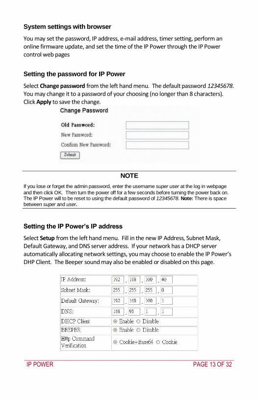
_____________________________________________________________________________
IP POWER PAGE 13 OF 32
System settings with browser
You may set the password IP address e-mail address timer setting perform an online firmware update and set the time of the IP Power through the IP Power control web pages
Setting the password for IP Power
Select Change password from the left hand menu The default password 12345678 You may change it to a password of your choosing (no longer than 8 characters) Click Apply to save the change
NOTE
If you lose or forget the admin password enter the username super user at the log in webpage
and then click OK Then turn the power off for a few seconds before turning the power back on The IP Power will to be reset to using the default password of 12345678 Note There is space between super and user
Setting the IP Powerrsquos IP address
Select Setup from the left hand menu Fill in the new IP Address Subnet Mask Default Gateway and DNS server address If your network has a DHCP server automatically allocating network settings you may choose to enable the IP Powerrsquos DHP Client The Beeper sound may also be enabled or disabled on this page
_____________________________________________________________________________
IP POWER PAGE 14 OF 32
If the IP Power is connected to your Local Area Network (LAN)
You may set a fixed IP address or have it automatically assigned by a DHCP server It is suggested that you use a fixed IP address so that it is always known After changing the IP Powerrsquos IP address type the new address in the address field of your web browser You can also use the ipEditexe tool to locate the IP Power
If the IP Power is connected to the Internet (WAN)
IP Address Enter the IP address provided by your ISP If IP Power is working with a router please refer to the network settings of the router The IP address format is xxxxxxxxxxxx yyyyy where yyyyy means the port number ranging from 1 to 32767
Subnet Mask Enter the Subnet Mask provided by your ISP If the IP Power is working with a router please refer to the network settings of the router Subnet Mask from 0 to 254 ( xxxxxxxxx0 ~ xxxxxxxxx254)
Default gateway Enter the Default Gateway provided by your ISP If the IP Power is working with a router please refer to the network settings of the router
DNS Server Enter the IP address of the DNS server provided by your ISP
DHCP Client Automatically obtain network settings from your ISP
If DHCP is disabled you must set the TCP port and default gateway If DHCP is enabled then the TCP port is preset to 80 (xxxxxxxxxxxx80) and the default gateway will be assigned by the DHCP server
If you specify a TCP port other than 80 enter it after the IP address of the IP Power when accessing the IP Power control web pages eg httpxxxxxxxxxxxxyyyyy
Beeper Setting Enable ndash activate the beeper sounds Disable ndash turn off beep
sounds When controlling the IP Power through the web pages the beeper if enabled beeps once to indicate an action has been successful
HTTP Command Verification specifies the HTTP authentication for the IP Power to use
_____________________________________________________________________________
IP POWER PAGE 15 OF 32
o Cookie +Base64 (allows HTTP command amp SDK control) o Cookie (allows HTTP command amp SDK control)
Email settings
The IP Power can be set to email its IP address to multiple recipients
Mail Server The SMTP server for sending email Please ensure that it is available
POP3Server Incoming Mail Server Enter IP address from your ISP for sending Internet IP address by E-mail
Username The SMTP username for sending email
Password The password for Usernamersquos account Note the password can be no longer than 8 characters
Sender The same of the sender to use This will often be usernameyourdomain
Receiver 1 ndash 3 The email addresses to receive the IP Powerrsquos IP address They will receive an email containing the IP Powerrsquos IP address each time your log in to the IP Power control web pages Each receiver may be no more than 50 characters
Subject The subject of the mail no more than 50 characters
Mail Body Type the content of the mail here It must not be left blank
_____________________________________________________________________________
IP POWER PAGE 16 OF 32
Click Save to save your settings
Power control using the time schedule
The IP Power can be set to power on or off power outlets at specified times Select Power Schedule from the left hand menu
Each power outlet has two rows one for the start of the schedule (eg powering an outlet on) and one for the end of the schedule (eg powering the outlet off two hours later) Additionally the Parameter column determines how regularly the schedule should be applied
Disable
Just Once
Every day
Work days every Monday to Friday
Weekend every Saturday and Sunday
Default outlet settings
When the IP Power is powered on each outlet will have power applied according to the default outlet settings In the example below all power outlets default to OFF when the IP Power is initially powered on
_____________________________________________________________________________
IP POWER PAGE 17 OF 32
Clock settings amp network time protocol (NTP)
You may manually set the IP Powerrsquos internal clock by specifying the year month day hour minutes and seconds
Alternately you may choose to synchronize with an NTP server by entering its IP address and your numeric Time Zone (relative to UTC) If your network or ISP doesnrsquot have an NTP server lists of public NTP servers are available on the web
Wake on LAN (WOL)
Through its network port the IP Power can send a Wake on LAN packet to a shutdown or hibernating PC on your network causing it to power up This facility presumes
1 The PCrsquos motherboard must support the WOL function and it must be enabled in the BIOS (typically under Power Management) The PC must be connected to the same Ethernet network as the IP Power via its network port
2 The PCrsquos network cardrsquos WOL connector must be connected to the motherboard or the network port must be integrated into the motherboard
After setting up the motherboard and network card use the WOL function by following two steps
Go to Network Wakeup on the IP Power control web pages
Enter the MAC address (the network cardrsquos physical address) of the PC and click Send ndash the PC will be powered on
_____________________________________________________________________________
IP POWER PAGE 18 OF 32
NOTE
To find out your network cardrsquos MAC address
Right click on the network connection icon Status Support Details The value in Physical Address is the MAC address
6 Firmware Update
Warning If you have not been advised to update the IP Powerrsquos firmware and do not have a new firmware file please do not go to this page
NOTE Before updating the IP Powerrsquos firmware ensure the IP Power control web pagesrsquo TCP port is set
to 80 (this is the default) otherwise the update may fail
Firmware updates are periodically released to update the functionality of the IP Power To update the IP Powerrsquos firmware select Firmware Update from the left hand menu
The following warning is displayed
_____________________________________________________________________________
IP POWER PAGE 19 OF 32
Warning Do not click Update if you do not have a firmware update file
Click Update the following window is displayed
Click Browse and locate the firmware update file Click Update to begin the update
Note When the update is complete you must wait at least one minute before you restart the IP Power
7 DDNS Settings
When connecting to the Internet the IP address you gain from ISP may be dynamically allocated so it may change each time the Internet connection reconnects This may result in the IP Power becoming uncontactable to remote clients as the new address is unknown Dynamic DNS addresses this issue by updating DNS records whenever the IP address changes The IP Power can utilize the free service provided by DynDNS (httpwwwdyndnscom) for this purpose The IP Power will always be contactable using its DynDNS address (eg ippowerdyndnsorg) regardless of its IP address
_____________________________________________________________________________
IP POWER PAGE 20 OF 32
First create a DynDNS account and create an account Create a dynamic DNS host for the IP Power eg ippowerdyndnsorg On the IP Power select DDNS from the left hand menu Enter the IP address and port of the DynDNS server You can find this out on your PC by selecting Start Run then type in cmd and typing ping wwwdyndnscom Enter the number in brackets (eg 6320819666) followed by 80 to denote the port In Your Domain enter the IP Powerrsquos DynDNS address eg ippowerdyndnsorg Enter the Username and Password for the DynDNS account you created Ensure Enable DDNS is set to TRUE Click Save Now each time the IP Power is powered on or Update Now is clicked the DynDNS address will be updated to the IP Powerrsquos current IP address Note that the change may take several minutes to propagate to your local DNS server If the IP Power cannot reach the DynDNS server without going through a proxy server select TRUE next to Proxy Enable Enter the IP address of the proxy server in Proxy IP and the port in Proxy Port
NOTE
The first time you configure DDNS click Update Now to set the DynDNS address
8 Control Using Telnet HTTP amp SNMP Commands
The IP Power is a principally a browser controlled unit with power control effected over the LAN using HTTP commands or a browser However it also provides alternate methods for directly setting and getting the status of the power outlets through Telnet commands and HTTP commands (which may be useful for controlling the IP Powerrsquos outlets using an automated script) and through SMNP Power outlet status and control using HTTP commands
The format of the HTTP command is
_____________________________________________________________________________
IP POWER PAGE 21 OF 32
httpusernamepasswordabcdSetcmdCMD=command+outlet_id=10+out
let_id=10 Where username The username you use to login to the IP Power (default is admin)
password The password you use to login to the IP Power (default is 12345678)
abcd The IP address of the IP Power (default is 192168050)
command GetPower to read the status (specifying outlets is not required) SetPower to turn on or off the ports (power setting for each outlet must
be specified after the command)
port_id (SetPower only) P60 Port 1 P61 Port 2 P62 Port 3 P63 Port 4 Example 1 The HTTP command httpadmin123456781921680 50SetcmdCMD=GetPower Returns the power status for each outlet in the following format (outlets 5 to 8 may be ignored) lthtmlgtP60=0P61=0P62=0P63=0P64=0P65=0P66=0P67=0lthtmlgt In the above example all outlets are off Example 2 The HTTP command httpadmin12345678192168050SetcmdCMD=SetPower+P60=1+P61=0+P62=0+P63=1
_____________________________________________________________________________
IP POWER PAGE 22 OF 32
Turns the power on for the first (P60) and fourth (P63) outlets and turns power off for the second (P61) and third (P62) outlets Returns the power status for each outlet in the following format lthtmlgtP60=1P61=0P62=0P63=1lthtmlgt Example 3 The HTTP command to control the 9258 operation at a specified time httpusernamepasswordXXXXXXXXXXXXSetcmdCMD=SetSchedule+Power =+YY=+MM=+DD=+HH=+MN=+SS=+PARAM=+ONOFF= Where Control parameters are 1A 1B 2A 2B 3A 3B 4A 4B A = connect power B = disconnect power YY=+MM=+DD=+HH=+MN=+SS= time parameter YY year (20YY) 01 = 2001 MM month (0 1-12) DD date (01-31) HH hour (24 hours 0- 23) MN minute (1-60) SS second (1-60) PARAM= time schedule parameter Parameter list as follows 128 Once only 127 Every day 31 Week days (Monday to Friday) 96 Weekend days (Saturday and Sunday) ONOFF= operate parameter 0 open 1 close For example
_____________________________________________________________________________
IP POWER PAGE 23 OF 32
http admin12345678192168110SetcmdCMD=SetSchedule+Power=1A+YY=2009+MM=02+DD=16+HH=06+MN=02+SS=16+PARAM=128+ONOFF=1 The above command controls the IP Power at IP address 19216810 user name is admin and password is 12345678 This 9258 will connect power of outlet 1 (p60) once only on 16th February 2009 at 602 am
NOTE Use + to separate each parameter eg to simply power on outlet 1 httpadmin12345678192168110SetcmdCMD=SetPower+P60=1
The command syntax is case sensitive so be selective when using upper and lower case in command format The free tool wget is useful for sending these HTTP commands For example
to send the command in Example 1 you could use wget ndashO -httpadmin12345678192168050SetcmdCMD=SetPower+P60=1+P61=0+P62=0+P63=1
Power outlet status and control using Telnet
Under DOS mode type ldquo Cgttelnet [IP9258] ldquo
To log in to the device use the syntax login=password
Typing help will give you the other commands that are available for the 9258 in telnet
_____________________________________________________________________________
IP POWER PAGE 24 OF 32
The getpower command reports the status of power outlets 1-4 The setpower command controls the power outlets 1-4 with ldquo0rdquo turning power off and ldquo1rdquo turning power on Example 1 setpower =11110000 (This will turn on power 1-4) Example 2 setpower =11000000 (This turns on power on 1 amp 2 and turns off power 3 amp 4)
NOTE Only the first four numbers are used You can select from 0 to turn off the power to 1 to turn on the
power However with 155 the syntax requires to use eight separte digits If you only use four digits the command will not work properly
_____________________________________________________________________________
IP POWER PAGE 25 OF 32
Power outlet status and control using SNMP
Reading status
snmpget -v 1 -c public 192168155 1361419258210 (read status of Power1)
snmpget -v 1 -c public 192168155 1361419258220 (read status of Power2) snmpget -v 1 -c public 192168155 1361419258230 (read status of Power3) snmpget -v 1 -c public 192168155 1361419258240 (read status of Power4)
(Return value as ldquoINTEGER 1 rdquo means power ON Return value as ldquoINTEGER 0 rdquo means power OFF)
_____________________________________________________________________________
IP POWER PAGE 26 OF 32
Control outlet command
snmpset -v 1 -c public 192168155 1361419258210 integer 1 (turn on Power1) snmpset -v 1 -c public 192168155 1361419258220 integer 0 (turn off Power2)
snmpset -v 1 -c public 192168155 1361419258230 integer 1 (turn on Power3) snmpset -v 1 -c public 192168155 1361419258240 integer 0 (turn off Power4)
Power cycle outlet command snmpset -v 1 -c public 192168155 1361419258310 integer 1 (powercycle No1)
snmpset -v 1 -c public 192168155 1361419258320 integer 1 (powercycle No2) snmpset -v 1 -c public 192168155 1361419258330 integer 1 (powercycle No3)
_____________________________________________________________________________
IP POWER PAGE 27 OF 32
snmpset -v 1 -c public 192168155 1361419258340 integer 1 (powercycle No4)
If the power is on the outlet will turn ldquoOFF to ON ldquo when the power cycle command is placed However if powered off the outlet will turn ldquoON to OFF to ON ldquo when place power cycle command
9 Frequently Asked Question
Q1 I forgot the password and can not enter the administration page now what can I do A1 Use the username super user when logging in to the webpage and then click OK Turn the IP Power off for a few seconds the turn it back on The default username of admin and password of 12345678 will be restored Note there is a space between super and user
10 Manual Control Mode
The IP Power is generally controlled from a local or remote computer however the outlets can also be controlled manually
NOTE
Before using the manual control function it is necessary to UNPLUG DISCONNECT all of the 4 outlets
To obtain manual control
_____________________________________________________________________________
IP POWER PAGE 28 OF 32
Press and hold the ONOFF button (depicted below) for a full 5 seconds or until a sustained beep noise is heard ndash this enables manual control mode which can be identified by the flashing outlet lights
The outlet light that is not flashing is the one currently under manual control ndash this outlet can be turned on or off by pressing the ONOFF button
To select an alternate outlet to control press the Cycle button (labeled with a circle with arrows on it)
To disable manual control mode press and hold the ONOFF button for 5 seconds or until you can hear a sustained beep noise ndash signifying the deactivation of manual control mode
Cycle (left) Select power outlet to manually control
ONOFF (right) Press and hold to enabledisable manual control mode press to turn onoff the outlet selected by the cycle button
11 IP Power Control Using Console Server
The IP Power 9258 is a simple browser controlled power switch without the security features needed for open public network connection Nor does it have any remote out-of-band dial-in support
However the IP Power can be configured securely and its outlets can be controlled in-band and out of band when used in conjunction with an Opengear console server
Out of band access
The Opengear console server provides secure remoteout-of-band access through a dial in modem (or through an alternate broadband connection) To configure the console server for dial-in access
_____________________________________________________________________________
IP POWER PAGE 29 OF 32
Connect a modem to the consolemodem port and configure the console server for dial-in
The IP Power can then be network or serially connected to the console server
SSH tunneled control through the Console Server
If the IP Power is connected on the remote LAN with the console server then it can be browser controlled
Configure the console server with the IP Power as a HTTP accessible Host This Managed Device can then be remotely controlled securely using SSH tunneling (SDT)
Configure the remote SDTConnector client to access the gateway (console server) and then to connect to the IP Power using HTTP (refer wwwopengearcomfaq267html for details)
Console Server serial control
The IP Power is a principally a browser controlled unit and its RS232 serial port mainly provides diagnostic and status information (eg sending out its IP address and power on messages during Power On Self Test) However the IP Power serial port also supports emergency power control To configure the IP Power for serial control
Connect the IP Power 9258s CONSOLE RS232 port to one of the console server serial ports (for CM4001 2 this interconnection will use a standard UTP Cat 5 cable with a 319000 adapter at each end and all other console servers will only require one 319000 adaptor)
Configured the console server serial port with a serially controlled PDU
_____________________________________________________________________________
IP POWER PAGE 30 OF 32
The IP Power outlets are then controlled by securely (HTTPS) accessing the Manage Power menu on the console server Management Console (refer wwwopengearcomfaq231html for details)
NOTE
The outlet control commands are sent from the console server to the IP Power over the serial port
The combination of out of band access and IP Power serial port control can be particularly useful in managing remote sites where a DSL router (interconnect the office LAN and the internet) may have become dysfunctional requiring a power reset
12 General IP Power Control Using Serial Port
The IP Power RS232 serial port mainly provides diagnostic and status information however the serial port can be used for emergency power control as covered in the previous section
Usage power-ip9258 ltportgt ltoutletgt [outlet] on|off|status
The serial control script below is used in the console server and should work on a normal Linux box
binsh
out_udelay=50000
_____________________________________________________________________________
IP POWER PAGE 31 OF 32
out_retries=3
in_udelay=100000
in_retries=10
port=$1
outlets=$2 cmd=$3 tmpfile=tmptmp$$
if [[ -z $port ]] || [[ -z $outlets ]] || [[ -z $cmd ]] then appname=`basename $0`
echo Usage $appname ltportgt ltoutletgt [outlet] on|off|status exit 1 fi
function ipp_chat () out=$1
in=$2 cat $port gt $tmpfile amp
cat_pid=$ trap rm $tmpfile kill $cat_pid EXIT
for (( i=0 i lt $out_retries i++ )) do for (( j = 0 j lt $out j++ )) do usleep $out_udelay
echo -n $out$j1 gt $port done echo gt $port
for (( j=0 j lt $in_retries j++ )) do usleep $in_udelay line=`grep $in $tmpfile`
if [[ -n $line ]] then break 2 fi
done done
rm $tmpfile kill $cat_pid
if [[ -n $line ]] then echo $line else
echo Command failed ($out) exit 1 fi
Suppress error messages from the shell
exec 2gt devnull Set up the serial port for the IP Power
_____________________________________________________________________________
IP POWER PAGE 32 OF 32
stty 14004cbea3031c7f15401011131a012f17160000000000000
000 lt $port Enable serial command mode
ipp_chat 0ADEBUG9258Z IP9258 DEBUG ON ampgt devnull Get current status
status_nibble=`ipp_chat 0Ap06Z p6 | sed sp6()1g`
Send the command the least significant bit is port 1 the most significant is port 4 A value of 0 is on 1 is off
outlet_mask=0 for o in $outlets do outlet_bit=$(( 1ltlt $o-1 ))
outlet_mask=$(( outlet_mask | $outlet_bit )) done status_nibble=`printf d 0x$status_nibble`
if [[ $cmd == on ]] then echo Powering on outlet $outlets status_nibble=`printf X $(( $status_nibble amp ~$outlet_mask ))`
ipp_chat 0AP06F$status_nibbleZ P6=F$status_nibble ampgt devnull echo Outlet $outlets powered on
elif [[ $cmd == off ]] then echo Powering off outlet $outlets status_nibble=`printf X $(( $status_nibble | $outlet_mask ))`
ipp_chat 0AP06F$status_nibbleZ P6=F$status_nibble ampgt devnull echo Outlet $outlets powered off
else for o in $outlets do outlet_bit=$(( 1ltlt $o-1 ))
echo -n Outlet $o is if [[ $(( $status_nibble amp $outlet_bit )) -eq $outlet_bit ]] then echo off
else echo on fi
done fi
Disable serial command mode ipp_chat 0ADEBUG0FFZ IP9258 DEBUG OFF ampgt devnull exit 0
_____________________________________________________________________________
IP POWER PAGE 14 OF 32
If the IP Power is connected to your Local Area Network (LAN)
You may set a fixed IP address or have it automatically assigned by a DHCP server It is suggested that you use a fixed IP address so that it is always known After changing the IP Powerrsquos IP address type the new address in the address field of your web browser You can also use the ipEditexe tool to locate the IP Power
If the IP Power is connected to the Internet (WAN)
IP Address Enter the IP address provided by your ISP If IP Power is working with a router please refer to the network settings of the router The IP address format is xxxxxxxxxxxx yyyyy where yyyyy means the port number ranging from 1 to 32767
Subnet Mask Enter the Subnet Mask provided by your ISP If the IP Power is working with a router please refer to the network settings of the router Subnet Mask from 0 to 254 ( xxxxxxxxx0 ~ xxxxxxxxx254)
Default gateway Enter the Default Gateway provided by your ISP If the IP Power is working with a router please refer to the network settings of the router
DNS Server Enter the IP address of the DNS server provided by your ISP
DHCP Client Automatically obtain network settings from your ISP
If DHCP is disabled you must set the TCP port and default gateway If DHCP is enabled then the TCP port is preset to 80 (xxxxxxxxxxxx80) and the default gateway will be assigned by the DHCP server
If you specify a TCP port other than 80 enter it after the IP address of the IP Power when accessing the IP Power control web pages eg httpxxxxxxxxxxxxyyyyy
Beeper Setting Enable ndash activate the beeper sounds Disable ndash turn off beep
sounds When controlling the IP Power through the web pages the beeper if enabled beeps once to indicate an action has been successful
HTTP Command Verification specifies the HTTP authentication for the IP Power to use
_____________________________________________________________________________
IP POWER PAGE 15 OF 32
o Cookie +Base64 (allows HTTP command amp SDK control) o Cookie (allows HTTP command amp SDK control)
Email settings
The IP Power can be set to email its IP address to multiple recipients
Mail Server The SMTP server for sending email Please ensure that it is available
POP3Server Incoming Mail Server Enter IP address from your ISP for sending Internet IP address by E-mail
Username The SMTP username for sending email
Password The password for Usernamersquos account Note the password can be no longer than 8 characters
Sender The same of the sender to use This will often be usernameyourdomain
Receiver 1 ndash 3 The email addresses to receive the IP Powerrsquos IP address They will receive an email containing the IP Powerrsquos IP address each time your log in to the IP Power control web pages Each receiver may be no more than 50 characters
Subject The subject of the mail no more than 50 characters
Mail Body Type the content of the mail here It must not be left blank
_____________________________________________________________________________
IP POWER PAGE 16 OF 32
Click Save to save your settings
Power control using the time schedule
The IP Power can be set to power on or off power outlets at specified times Select Power Schedule from the left hand menu
Each power outlet has two rows one for the start of the schedule (eg powering an outlet on) and one for the end of the schedule (eg powering the outlet off two hours later) Additionally the Parameter column determines how regularly the schedule should be applied
Disable
Just Once
Every day
Work days every Monday to Friday
Weekend every Saturday and Sunday
Default outlet settings
When the IP Power is powered on each outlet will have power applied according to the default outlet settings In the example below all power outlets default to OFF when the IP Power is initially powered on
_____________________________________________________________________________
IP POWER PAGE 17 OF 32
Clock settings amp network time protocol (NTP)
You may manually set the IP Powerrsquos internal clock by specifying the year month day hour minutes and seconds
Alternately you may choose to synchronize with an NTP server by entering its IP address and your numeric Time Zone (relative to UTC) If your network or ISP doesnrsquot have an NTP server lists of public NTP servers are available on the web
Wake on LAN (WOL)
Through its network port the IP Power can send a Wake on LAN packet to a shutdown or hibernating PC on your network causing it to power up This facility presumes
1 The PCrsquos motherboard must support the WOL function and it must be enabled in the BIOS (typically under Power Management) The PC must be connected to the same Ethernet network as the IP Power via its network port
2 The PCrsquos network cardrsquos WOL connector must be connected to the motherboard or the network port must be integrated into the motherboard
After setting up the motherboard and network card use the WOL function by following two steps
Go to Network Wakeup on the IP Power control web pages
Enter the MAC address (the network cardrsquos physical address) of the PC and click Send ndash the PC will be powered on
_____________________________________________________________________________
IP POWER PAGE 18 OF 32
NOTE
To find out your network cardrsquos MAC address
Right click on the network connection icon Status Support Details The value in Physical Address is the MAC address
6 Firmware Update
Warning If you have not been advised to update the IP Powerrsquos firmware and do not have a new firmware file please do not go to this page
NOTE Before updating the IP Powerrsquos firmware ensure the IP Power control web pagesrsquo TCP port is set
to 80 (this is the default) otherwise the update may fail
Firmware updates are periodically released to update the functionality of the IP Power To update the IP Powerrsquos firmware select Firmware Update from the left hand menu
The following warning is displayed
_____________________________________________________________________________
IP POWER PAGE 19 OF 32
Warning Do not click Update if you do not have a firmware update file
Click Update the following window is displayed
Click Browse and locate the firmware update file Click Update to begin the update
Note When the update is complete you must wait at least one minute before you restart the IP Power
7 DDNS Settings
When connecting to the Internet the IP address you gain from ISP may be dynamically allocated so it may change each time the Internet connection reconnects This may result in the IP Power becoming uncontactable to remote clients as the new address is unknown Dynamic DNS addresses this issue by updating DNS records whenever the IP address changes The IP Power can utilize the free service provided by DynDNS (httpwwwdyndnscom) for this purpose The IP Power will always be contactable using its DynDNS address (eg ippowerdyndnsorg) regardless of its IP address
_____________________________________________________________________________
IP POWER PAGE 20 OF 32
First create a DynDNS account and create an account Create a dynamic DNS host for the IP Power eg ippowerdyndnsorg On the IP Power select DDNS from the left hand menu Enter the IP address and port of the DynDNS server You can find this out on your PC by selecting Start Run then type in cmd and typing ping wwwdyndnscom Enter the number in brackets (eg 6320819666) followed by 80 to denote the port In Your Domain enter the IP Powerrsquos DynDNS address eg ippowerdyndnsorg Enter the Username and Password for the DynDNS account you created Ensure Enable DDNS is set to TRUE Click Save Now each time the IP Power is powered on or Update Now is clicked the DynDNS address will be updated to the IP Powerrsquos current IP address Note that the change may take several minutes to propagate to your local DNS server If the IP Power cannot reach the DynDNS server without going through a proxy server select TRUE next to Proxy Enable Enter the IP address of the proxy server in Proxy IP and the port in Proxy Port
NOTE
The first time you configure DDNS click Update Now to set the DynDNS address
8 Control Using Telnet HTTP amp SNMP Commands
The IP Power is a principally a browser controlled unit with power control effected over the LAN using HTTP commands or a browser However it also provides alternate methods for directly setting and getting the status of the power outlets through Telnet commands and HTTP commands (which may be useful for controlling the IP Powerrsquos outlets using an automated script) and through SMNP Power outlet status and control using HTTP commands
The format of the HTTP command is
_____________________________________________________________________________
IP POWER PAGE 21 OF 32
httpusernamepasswordabcdSetcmdCMD=command+outlet_id=10+out
let_id=10 Where username The username you use to login to the IP Power (default is admin)
password The password you use to login to the IP Power (default is 12345678)
abcd The IP address of the IP Power (default is 192168050)
command GetPower to read the status (specifying outlets is not required) SetPower to turn on or off the ports (power setting for each outlet must
be specified after the command)
port_id (SetPower only) P60 Port 1 P61 Port 2 P62 Port 3 P63 Port 4 Example 1 The HTTP command httpadmin123456781921680 50SetcmdCMD=GetPower Returns the power status for each outlet in the following format (outlets 5 to 8 may be ignored) lthtmlgtP60=0P61=0P62=0P63=0P64=0P65=0P66=0P67=0lthtmlgt In the above example all outlets are off Example 2 The HTTP command httpadmin12345678192168050SetcmdCMD=SetPower+P60=1+P61=0+P62=0+P63=1
_____________________________________________________________________________
IP POWER PAGE 22 OF 32
Turns the power on for the first (P60) and fourth (P63) outlets and turns power off for the second (P61) and third (P62) outlets Returns the power status for each outlet in the following format lthtmlgtP60=1P61=0P62=0P63=1lthtmlgt Example 3 The HTTP command to control the 9258 operation at a specified time httpusernamepasswordXXXXXXXXXXXXSetcmdCMD=SetSchedule+Power =+YY=+MM=+DD=+HH=+MN=+SS=+PARAM=+ONOFF= Where Control parameters are 1A 1B 2A 2B 3A 3B 4A 4B A = connect power B = disconnect power YY=+MM=+DD=+HH=+MN=+SS= time parameter YY year (20YY) 01 = 2001 MM month (0 1-12) DD date (01-31) HH hour (24 hours 0- 23) MN minute (1-60) SS second (1-60) PARAM= time schedule parameter Parameter list as follows 128 Once only 127 Every day 31 Week days (Monday to Friday) 96 Weekend days (Saturday and Sunday) ONOFF= operate parameter 0 open 1 close For example
_____________________________________________________________________________
IP POWER PAGE 23 OF 32
http admin12345678192168110SetcmdCMD=SetSchedule+Power=1A+YY=2009+MM=02+DD=16+HH=06+MN=02+SS=16+PARAM=128+ONOFF=1 The above command controls the IP Power at IP address 19216810 user name is admin and password is 12345678 This 9258 will connect power of outlet 1 (p60) once only on 16th February 2009 at 602 am
NOTE Use + to separate each parameter eg to simply power on outlet 1 httpadmin12345678192168110SetcmdCMD=SetPower+P60=1
The command syntax is case sensitive so be selective when using upper and lower case in command format The free tool wget is useful for sending these HTTP commands For example
to send the command in Example 1 you could use wget ndashO -httpadmin12345678192168050SetcmdCMD=SetPower+P60=1+P61=0+P62=0+P63=1
Power outlet status and control using Telnet
Under DOS mode type ldquo Cgttelnet [IP9258] ldquo
To log in to the device use the syntax login=password
Typing help will give you the other commands that are available for the 9258 in telnet
_____________________________________________________________________________
IP POWER PAGE 24 OF 32
The getpower command reports the status of power outlets 1-4 The setpower command controls the power outlets 1-4 with ldquo0rdquo turning power off and ldquo1rdquo turning power on Example 1 setpower =11110000 (This will turn on power 1-4) Example 2 setpower =11000000 (This turns on power on 1 amp 2 and turns off power 3 amp 4)
NOTE Only the first four numbers are used You can select from 0 to turn off the power to 1 to turn on the
power However with 155 the syntax requires to use eight separte digits If you only use four digits the command will not work properly
_____________________________________________________________________________
IP POWER PAGE 25 OF 32
Power outlet status and control using SNMP
Reading status
snmpget -v 1 -c public 192168155 1361419258210 (read status of Power1)
snmpget -v 1 -c public 192168155 1361419258220 (read status of Power2) snmpget -v 1 -c public 192168155 1361419258230 (read status of Power3) snmpget -v 1 -c public 192168155 1361419258240 (read status of Power4)
(Return value as ldquoINTEGER 1 rdquo means power ON Return value as ldquoINTEGER 0 rdquo means power OFF)
_____________________________________________________________________________
IP POWER PAGE 26 OF 32
Control outlet command
snmpset -v 1 -c public 192168155 1361419258210 integer 1 (turn on Power1) snmpset -v 1 -c public 192168155 1361419258220 integer 0 (turn off Power2)
snmpset -v 1 -c public 192168155 1361419258230 integer 1 (turn on Power3) snmpset -v 1 -c public 192168155 1361419258240 integer 0 (turn off Power4)
Power cycle outlet command snmpset -v 1 -c public 192168155 1361419258310 integer 1 (powercycle No1)
snmpset -v 1 -c public 192168155 1361419258320 integer 1 (powercycle No2) snmpset -v 1 -c public 192168155 1361419258330 integer 1 (powercycle No3)
_____________________________________________________________________________
IP POWER PAGE 27 OF 32
snmpset -v 1 -c public 192168155 1361419258340 integer 1 (powercycle No4)
If the power is on the outlet will turn ldquoOFF to ON ldquo when the power cycle command is placed However if powered off the outlet will turn ldquoON to OFF to ON ldquo when place power cycle command
9 Frequently Asked Question
Q1 I forgot the password and can not enter the administration page now what can I do A1 Use the username super user when logging in to the webpage and then click OK Turn the IP Power off for a few seconds the turn it back on The default username of admin and password of 12345678 will be restored Note there is a space between super and user
10 Manual Control Mode
The IP Power is generally controlled from a local or remote computer however the outlets can also be controlled manually
NOTE
Before using the manual control function it is necessary to UNPLUG DISCONNECT all of the 4 outlets
To obtain manual control
_____________________________________________________________________________
IP POWER PAGE 28 OF 32
Press and hold the ONOFF button (depicted below) for a full 5 seconds or until a sustained beep noise is heard ndash this enables manual control mode which can be identified by the flashing outlet lights
The outlet light that is not flashing is the one currently under manual control ndash this outlet can be turned on or off by pressing the ONOFF button
To select an alternate outlet to control press the Cycle button (labeled with a circle with arrows on it)
To disable manual control mode press and hold the ONOFF button for 5 seconds or until you can hear a sustained beep noise ndash signifying the deactivation of manual control mode
Cycle (left) Select power outlet to manually control
ONOFF (right) Press and hold to enabledisable manual control mode press to turn onoff the outlet selected by the cycle button
11 IP Power Control Using Console Server
The IP Power 9258 is a simple browser controlled power switch without the security features needed for open public network connection Nor does it have any remote out-of-band dial-in support
However the IP Power can be configured securely and its outlets can be controlled in-band and out of band when used in conjunction with an Opengear console server
Out of band access
The Opengear console server provides secure remoteout-of-band access through a dial in modem (or through an alternate broadband connection) To configure the console server for dial-in access
_____________________________________________________________________________
IP POWER PAGE 29 OF 32
Connect a modem to the consolemodem port and configure the console server for dial-in
The IP Power can then be network or serially connected to the console server
SSH tunneled control through the Console Server
If the IP Power is connected on the remote LAN with the console server then it can be browser controlled
Configure the console server with the IP Power as a HTTP accessible Host This Managed Device can then be remotely controlled securely using SSH tunneling (SDT)
Configure the remote SDTConnector client to access the gateway (console server) and then to connect to the IP Power using HTTP (refer wwwopengearcomfaq267html for details)
Console Server serial control
The IP Power is a principally a browser controlled unit and its RS232 serial port mainly provides diagnostic and status information (eg sending out its IP address and power on messages during Power On Self Test) However the IP Power serial port also supports emergency power control To configure the IP Power for serial control
Connect the IP Power 9258s CONSOLE RS232 port to one of the console server serial ports (for CM4001 2 this interconnection will use a standard UTP Cat 5 cable with a 319000 adapter at each end and all other console servers will only require one 319000 adaptor)
Configured the console server serial port with a serially controlled PDU
_____________________________________________________________________________
IP POWER PAGE 30 OF 32
The IP Power outlets are then controlled by securely (HTTPS) accessing the Manage Power menu on the console server Management Console (refer wwwopengearcomfaq231html for details)
NOTE
The outlet control commands are sent from the console server to the IP Power over the serial port
The combination of out of band access and IP Power serial port control can be particularly useful in managing remote sites where a DSL router (interconnect the office LAN and the internet) may have become dysfunctional requiring a power reset
12 General IP Power Control Using Serial Port
The IP Power RS232 serial port mainly provides diagnostic and status information however the serial port can be used for emergency power control as covered in the previous section
Usage power-ip9258 ltportgt ltoutletgt [outlet] on|off|status
The serial control script below is used in the console server and should work on a normal Linux box
binsh
out_udelay=50000
_____________________________________________________________________________
IP POWER PAGE 31 OF 32
out_retries=3
in_udelay=100000
in_retries=10
port=$1
outlets=$2 cmd=$3 tmpfile=tmptmp$$
if [[ -z $port ]] || [[ -z $outlets ]] || [[ -z $cmd ]] then appname=`basename $0`
echo Usage $appname ltportgt ltoutletgt [outlet] on|off|status exit 1 fi
function ipp_chat () out=$1
in=$2 cat $port gt $tmpfile amp
cat_pid=$ trap rm $tmpfile kill $cat_pid EXIT
for (( i=0 i lt $out_retries i++ )) do for (( j = 0 j lt $out j++ )) do usleep $out_udelay
echo -n $out$j1 gt $port done echo gt $port
for (( j=0 j lt $in_retries j++ )) do usleep $in_udelay line=`grep $in $tmpfile`
if [[ -n $line ]] then break 2 fi
done done
rm $tmpfile kill $cat_pid
if [[ -n $line ]] then echo $line else
echo Command failed ($out) exit 1 fi
Suppress error messages from the shell
exec 2gt devnull Set up the serial port for the IP Power
_____________________________________________________________________________
IP POWER PAGE 32 OF 32
stty 14004cbea3031c7f15401011131a012f17160000000000000
000 lt $port Enable serial command mode
ipp_chat 0ADEBUG9258Z IP9258 DEBUG ON ampgt devnull Get current status
status_nibble=`ipp_chat 0Ap06Z p6 | sed sp6()1g`
Send the command the least significant bit is port 1 the most significant is port 4 A value of 0 is on 1 is off
outlet_mask=0 for o in $outlets do outlet_bit=$(( 1ltlt $o-1 ))
outlet_mask=$(( outlet_mask | $outlet_bit )) done status_nibble=`printf d 0x$status_nibble`
if [[ $cmd == on ]] then echo Powering on outlet $outlets status_nibble=`printf X $(( $status_nibble amp ~$outlet_mask ))`
ipp_chat 0AP06F$status_nibbleZ P6=F$status_nibble ampgt devnull echo Outlet $outlets powered on
elif [[ $cmd == off ]] then echo Powering off outlet $outlets status_nibble=`printf X $(( $status_nibble | $outlet_mask ))`
ipp_chat 0AP06F$status_nibbleZ P6=F$status_nibble ampgt devnull echo Outlet $outlets powered off
else for o in $outlets do outlet_bit=$(( 1ltlt $o-1 ))
echo -n Outlet $o is if [[ $(( $status_nibble amp $outlet_bit )) -eq $outlet_bit ]] then echo off
else echo on fi
done fi
Disable serial command mode ipp_chat 0ADEBUG0FFZ IP9258 DEBUG OFF ampgt devnull exit 0
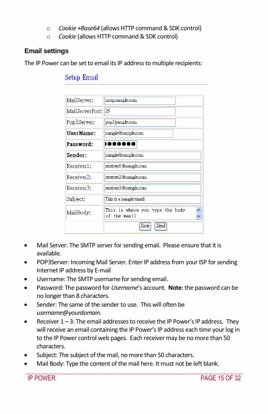
_____________________________________________________________________________
IP POWER PAGE 15 OF 32
o Cookie +Base64 (allows HTTP command amp SDK control) o Cookie (allows HTTP command amp SDK control)
Email settings
The IP Power can be set to email its IP address to multiple recipients
Mail Server The SMTP server for sending email Please ensure that it is available
POP3Server Incoming Mail Server Enter IP address from your ISP for sending Internet IP address by E-mail
Username The SMTP username for sending email
Password The password for Usernamersquos account Note the password can be no longer than 8 characters
Sender The same of the sender to use This will often be usernameyourdomain
Receiver 1 ndash 3 The email addresses to receive the IP Powerrsquos IP address They will receive an email containing the IP Powerrsquos IP address each time your log in to the IP Power control web pages Each receiver may be no more than 50 characters
Subject The subject of the mail no more than 50 characters
Mail Body Type the content of the mail here It must not be left blank
_____________________________________________________________________________
IP POWER PAGE 16 OF 32
Click Save to save your settings
Power control using the time schedule
The IP Power can be set to power on or off power outlets at specified times Select Power Schedule from the left hand menu
Each power outlet has two rows one for the start of the schedule (eg powering an outlet on) and one for the end of the schedule (eg powering the outlet off two hours later) Additionally the Parameter column determines how regularly the schedule should be applied
Disable
Just Once
Every day
Work days every Monday to Friday
Weekend every Saturday and Sunday
Default outlet settings
When the IP Power is powered on each outlet will have power applied according to the default outlet settings In the example below all power outlets default to OFF when the IP Power is initially powered on
_____________________________________________________________________________
IP POWER PAGE 17 OF 32
Clock settings amp network time protocol (NTP)
You may manually set the IP Powerrsquos internal clock by specifying the year month day hour minutes and seconds
Alternately you may choose to synchronize with an NTP server by entering its IP address and your numeric Time Zone (relative to UTC) If your network or ISP doesnrsquot have an NTP server lists of public NTP servers are available on the web
Wake on LAN (WOL)
Through its network port the IP Power can send a Wake on LAN packet to a shutdown or hibernating PC on your network causing it to power up This facility presumes
1 The PCrsquos motherboard must support the WOL function and it must be enabled in the BIOS (typically under Power Management) The PC must be connected to the same Ethernet network as the IP Power via its network port
2 The PCrsquos network cardrsquos WOL connector must be connected to the motherboard or the network port must be integrated into the motherboard
After setting up the motherboard and network card use the WOL function by following two steps
Go to Network Wakeup on the IP Power control web pages
Enter the MAC address (the network cardrsquos physical address) of the PC and click Send ndash the PC will be powered on
_____________________________________________________________________________
IP POWER PAGE 18 OF 32
NOTE
To find out your network cardrsquos MAC address
Right click on the network connection icon Status Support Details The value in Physical Address is the MAC address
6 Firmware Update
Warning If you have not been advised to update the IP Powerrsquos firmware and do not have a new firmware file please do not go to this page
NOTE Before updating the IP Powerrsquos firmware ensure the IP Power control web pagesrsquo TCP port is set
to 80 (this is the default) otherwise the update may fail
Firmware updates are periodically released to update the functionality of the IP Power To update the IP Powerrsquos firmware select Firmware Update from the left hand menu
The following warning is displayed
_____________________________________________________________________________
IP POWER PAGE 19 OF 32
Warning Do not click Update if you do not have a firmware update file
Click Update the following window is displayed
Click Browse and locate the firmware update file Click Update to begin the update
Note When the update is complete you must wait at least one minute before you restart the IP Power
7 DDNS Settings
When connecting to the Internet the IP address you gain from ISP may be dynamically allocated so it may change each time the Internet connection reconnects This may result in the IP Power becoming uncontactable to remote clients as the new address is unknown Dynamic DNS addresses this issue by updating DNS records whenever the IP address changes The IP Power can utilize the free service provided by DynDNS (httpwwwdyndnscom) for this purpose The IP Power will always be contactable using its DynDNS address (eg ippowerdyndnsorg) regardless of its IP address
_____________________________________________________________________________
IP POWER PAGE 20 OF 32
First create a DynDNS account and create an account Create a dynamic DNS host for the IP Power eg ippowerdyndnsorg On the IP Power select DDNS from the left hand menu Enter the IP address and port of the DynDNS server You can find this out on your PC by selecting Start Run then type in cmd and typing ping wwwdyndnscom Enter the number in brackets (eg 6320819666) followed by 80 to denote the port In Your Domain enter the IP Powerrsquos DynDNS address eg ippowerdyndnsorg Enter the Username and Password for the DynDNS account you created Ensure Enable DDNS is set to TRUE Click Save Now each time the IP Power is powered on or Update Now is clicked the DynDNS address will be updated to the IP Powerrsquos current IP address Note that the change may take several minutes to propagate to your local DNS server If the IP Power cannot reach the DynDNS server without going through a proxy server select TRUE next to Proxy Enable Enter the IP address of the proxy server in Proxy IP and the port in Proxy Port
NOTE
The first time you configure DDNS click Update Now to set the DynDNS address
8 Control Using Telnet HTTP amp SNMP Commands
The IP Power is a principally a browser controlled unit with power control effected over the LAN using HTTP commands or a browser However it also provides alternate methods for directly setting and getting the status of the power outlets through Telnet commands and HTTP commands (which may be useful for controlling the IP Powerrsquos outlets using an automated script) and through SMNP Power outlet status and control using HTTP commands
The format of the HTTP command is
_____________________________________________________________________________
IP POWER PAGE 21 OF 32
httpusernamepasswordabcdSetcmdCMD=command+outlet_id=10+out
let_id=10 Where username The username you use to login to the IP Power (default is admin)
password The password you use to login to the IP Power (default is 12345678)
abcd The IP address of the IP Power (default is 192168050)
command GetPower to read the status (specifying outlets is not required) SetPower to turn on or off the ports (power setting for each outlet must
be specified after the command)
port_id (SetPower only) P60 Port 1 P61 Port 2 P62 Port 3 P63 Port 4 Example 1 The HTTP command httpadmin123456781921680 50SetcmdCMD=GetPower Returns the power status for each outlet in the following format (outlets 5 to 8 may be ignored) lthtmlgtP60=0P61=0P62=0P63=0P64=0P65=0P66=0P67=0lthtmlgt In the above example all outlets are off Example 2 The HTTP command httpadmin12345678192168050SetcmdCMD=SetPower+P60=1+P61=0+P62=0+P63=1
_____________________________________________________________________________
IP POWER PAGE 22 OF 32
Turns the power on for the first (P60) and fourth (P63) outlets and turns power off for the second (P61) and third (P62) outlets Returns the power status for each outlet in the following format lthtmlgtP60=1P61=0P62=0P63=1lthtmlgt Example 3 The HTTP command to control the 9258 operation at a specified time httpusernamepasswordXXXXXXXXXXXXSetcmdCMD=SetSchedule+Power =+YY=+MM=+DD=+HH=+MN=+SS=+PARAM=+ONOFF= Where Control parameters are 1A 1B 2A 2B 3A 3B 4A 4B A = connect power B = disconnect power YY=+MM=+DD=+HH=+MN=+SS= time parameter YY year (20YY) 01 = 2001 MM month (0 1-12) DD date (01-31) HH hour (24 hours 0- 23) MN minute (1-60) SS second (1-60) PARAM= time schedule parameter Parameter list as follows 128 Once only 127 Every day 31 Week days (Monday to Friday) 96 Weekend days (Saturday and Sunday) ONOFF= operate parameter 0 open 1 close For example
_____________________________________________________________________________
IP POWER PAGE 23 OF 32
http admin12345678192168110SetcmdCMD=SetSchedule+Power=1A+YY=2009+MM=02+DD=16+HH=06+MN=02+SS=16+PARAM=128+ONOFF=1 The above command controls the IP Power at IP address 19216810 user name is admin and password is 12345678 This 9258 will connect power of outlet 1 (p60) once only on 16th February 2009 at 602 am
NOTE Use + to separate each parameter eg to simply power on outlet 1 httpadmin12345678192168110SetcmdCMD=SetPower+P60=1
The command syntax is case sensitive so be selective when using upper and lower case in command format The free tool wget is useful for sending these HTTP commands For example
to send the command in Example 1 you could use wget ndashO -httpadmin12345678192168050SetcmdCMD=SetPower+P60=1+P61=0+P62=0+P63=1
Power outlet status and control using Telnet
Under DOS mode type ldquo Cgttelnet [IP9258] ldquo
To log in to the device use the syntax login=password
Typing help will give you the other commands that are available for the 9258 in telnet
_____________________________________________________________________________
IP POWER PAGE 24 OF 32
The getpower command reports the status of power outlets 1-4 The setpower command controls the power outlets 1-4 with ldquo0rdquo turning power off and ldquo1rdquo turning power on Example 1 setpower =11110000 (This will turn on power 1-4) Example 2 setpower =11000000 (This turns on power on 1 amp 2 and turns off power 3 amp 4)
NOTE Only the first four numbers are used You can select from 0 to turn off the power to 1 to turn on the
power However with 155 the syntax requires to use eight separte digits If you only use four digits the command will not work properly
_____________________________________________________________________________
IP POWER PAGE 25 OF 32
Power outlet status and control using SNMP
Reading status
snmpget -v 1 -c public 192168155 1361419258210 (read status of Power1)
snmpget -v 1 -c public 192168155 1361419258220 (read status of Power2) snmpget -v 1 -c public 192168155 1361419258230 (read status of Power3) snmpget -v 1 -c public 192168155 1361419258240 (read status of Power4)
(Return value as ldquoINTEGER 1 rdquo means power ON Return value as ldquoINTEGER 0 rdquo means power OFF)
_____________________________________________________________________________
IP POWER PAGE 26 OF 32
Control outlet command
snmpset -v 1 -c public 192168155 1361419258210 integer 1 (turn on Power1) snmpset -v 1 -c public 192168155 1361419258220 integer 0 (turn off Power2)
snmpset -v 1 -c public 192168155 1361419258230 integer 1 (turn on Power3) snmpset -v 1 -c public 192168155 1361419258240 integer 0 (turn off Power4)
Power cycle outlet command snmpset -v 1 -c public 192168155 1361419258310 integer 1 (powercycle No1)
snmpset -v 1 -c public 192168155 1361419258320 integer 1 (powercycle No2) snmpset -v 1 -c public 192168155 1361419258330 integer 1 (powercycle No3)
_____________________________________________________________________________
IP POWER PAGE 27 OF 32
snmpset -v 1 -c public 192168155 1361419258340 integer 1 (powercycle No4)
If the power is on the outlet will turn ldquoOFF to ON ldquo when the power cycle command is placed However if powered off the outlet will turn ldquoON to OFF to ON ldquo when place power cycle command
9 Frequently Asked Question
Q1 I forgot the password and can not enter the administration page now what can I do A1 Use the username super user when logging in to the webpage and then click OK Turn the IP Power off for a few seconds the turn it back on The default username of admin and password of 12345678 will be restored Note there is a space between super and user
10 Manual Control Mode
The IP Power is generally controlled from a local or remote computer however the outlets can also be controlled manually
NOTE
Before using the manual control function it is necessary to UNPLUG DISCONNECT all of the 4 outlets
To obtain manual control
_____________________________________________________________________________
IP POWER PAGE 28 OF 32
Press and hold the ONOFF button (depicted below) for a full 5 seconds or until a sustained beep noise is heard ndash this enables manual control mode which can be identified by the flashing outlet lights
The outlet light that is not flashing is the one currently under manual control ndash this outlet can be turned on or off by pressing the ONOFF button
To select an alternate outlet to control press the Cycle button (labeled with a circle with arrows on it)
To disable manual control mode press and hold the ONOFF button for 5 seconds or until you can hear a sustained beep noise ndash signifying the deactivation of manual control mode
Cycle (left) Select power outlet to manually control
ONOFF (right) Press and hold to enabledisable manual control mode press to turn onoff the outlet selected by the cycle button
11 IP Power Control Using Console Server
The IP Power 9258 is a simple browser controlled power switch without the security features needed for open public network connection Nor does it have any remote out-of-band dial-in support
However the IP Power can be configured securely and its outlets can be controlled in-band and out of band when used in conjunction with an Opengear console server
Out of band access
The Opengear console server provides secure remoteout-of-band access through a dial in modem (or through an alternate broadband connection) To configure the console server for dial-in access
_____________________________________________________________________________
IP POWER PAGE 29 OF 32
Connect a modem to the consolemodem port and configure the console server for dial-in
The IP Power can then be network or serially connected to the console server
SSH tunneled control through the Console Server
If the IP Power is connected on the remote LAN with the console server then it can be browser controlled
Configure the console server with the IP Power as a HTTP accessible Host This Managed Device can then be remotely controlled securely using SSH tunneling (SDT)
Configure the remote SDTConnector client to access the gateway (console server) and then to connect to the IP Power using HTTP (refer wwwopengearcomfaq267html for details)
Console Server serial control
The IP Power is a principally a browser controlled unit and its RS232 serial port mainly provides diagnostic and status information (eg sending out its IP address and power on messages during Power On Self Test) However the IP Power serial port also supports emergency power control To configure the IP Power for serial control
Connect the IP Power 9258s CONSOLE RS232 port to one of the console server serial ports (for CM4001 2 this interconnection will use a standard UTP Cat 5 cable with a 319000 adapter at each end and all other console servers will only require one 319000 adaptor)
Configured the console server serial port with a serially controlled PDU
_____________________________________________________________________________
IP POWER PAGE 30 OF 32
The IP Power outlets are then controlled by securely (HTTPS) accessing the Manage Power menu on the console server Management Console (refer wwwopengearcomfaq231html for details)
NOTE
The outlet control commands are sent from the console server to the IP Power over the serial port
The combination of out of band access and IP Power serial port control can be particularly useful in managing remote sites where a DSL router (interconnect the office LAN and the internet) may have become dysfunctional requiring a power reset
12 General IP Power Control Using Serial Port
The IP Power RS232 serial port mainly provides diagnostic and status information however the serial port can be used for emergency power control as covered in the previous section
Usage power-ip9258 ltportgt ltoutletgt [outlet] on|off|status
The serial control script below is used in the console server and should work on a normal Linux box
binsh
out_udelay=50000
_____________________________________________________________________________
IP POWER PAGE 31 OF 32
out_retries=3
in_udelay=100000
in_retries=10
port=$1
outlets=$2 cmd=$3 tmpfile=tmptmp$$
if [[ -z $port ]] || [[ -z $outlets ]] || [[ -z $cmd ]] then appname=`basename $0`
echo Usage $appname ltportgt ltoutletgt [outlet] on|off|status exit 1 fi
function ipp_chat () out=$1
in=$2 cat $port gt $tmpfile amp
cat_pid=$ trap rm $tmpfile kill $cat_pid EXIT
for (( i=0 i lt $out_retries i++ )) do for (( j = 0 j lt $out j++ )) do usleep $out_udelay
echo -n $out$j1 gt $port done echo gt $port
for (( j=0 j lt $in_retries j++ )) do usleep $in_udelay line=`grep $in $tmpfile`
if [[ -n $line ]] then break 2 fi
done done
rm $tmpfile kill $cat_pid
if [[ -n $line ]] then echo $line else
echo Command failed ($out) exit 1 fi
Suppress error messages from the shell
exec 2gt devnull Set up the serial port for the IP Power
_____________________________________________________________________________
IP POWER PAGE 32 OF 32
stty 14004cbea3031c7f15401011131a012f17160000000000000
000 lt $port Enable serial command mode
ipp_chat 0ADEBUG9258Z IP9258 DEBUG ON ampgt devnull Get current status
status_nibble=`ipp_chat 0Ap06Z p6 | sed sp6()1g`
Send the command the least significant bit is port 1 the most significant is port 4 A value of 0 is on 1 is off
outlet_mask=0 for o in $outlets do outlet_bit=$(( 1ltlt $o-1 ))
outlet_mask=$(( outlet_mask | $outlet_bit )) done status_nibble=`printf d 0x$status_nibble`
if [[ $cmd == on ]] then echo Powering on outlet $outlets status_nibble=`printf X $(( $status_nibble amp ~$outlet_mask ))`
ipp_chat 0AP06F$status_nibbleZ P6=F$status_nibble ampgt devnull echo Outlet $outlets powered on
elif [[ $cmd == off ]] then echo Powering off outlet $outlets status_nibble=`printf X $(( $status_nibble | $outlet_mask ))`
ipp_chat 0AP06F$status_nibbleZ P6=F$status_nibble ampgt devnull echo Outlet $outlets powered off
else for o in $outlets do outlet_bit=$(( 1ltlt $o-1 ))
echo -n Outlet $o is if [[ $(( $status_nibble amp $outlet_bit )) -eq $outlet_bit ]] then echo off
else echo on fi
done fi
Disable serial command mode ipp_chat 0ADEBUG0FFZ IP9258 DEBUG OFF ampgt devnull exit 0
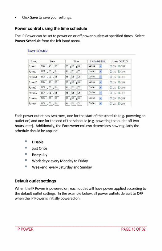
_____________________________________________________________________________
IP POWER PAGE 16 OF 32
Click Save to save your settings
Power control using the time schedule
The IP Power can be set to power on or off power outlets at specified times Select Power Schedule from the left hand menu
Each power outlet has two rows one for the start of the schedule (eg powering an outlet on) and one for the end of the schedule (eg powering the outlet off two hours later) Additionally the Parameter column determines how regularly the schedule should be applied
Disable
Just Once
Every day
Work days every Monday to Friday
Weekend every Saturday and Sunday
Default outlet settings
When the IP Power is powered on each outlet will have power applied according to the default outlet settings In the example below all power outlets default to OFF when the IP Power is initially powered on
_____________________________________________________________________________
IP POWER PAGE 17 OF 32
Clock settings amp network time protocol (NTP)
You may manually set the IP Powerrsquos internal clock by specifying the year month day hour minutes and seconds
Alternately you may choose to synchronize with an NTP server by entering its IP address and your numeric Time Zone (relative to UTC) If your network or ISP doesnrsquot have an NTP server lists of public NTP servers are available on the web
Wake on LAN (WOL)
Through its network port the IP Power can send a Wake on LAN packet to a shutdown or hibernating PC on your network causing it to power up This facility presumes
1 The PCrsquos motherboard must support the WOL function and it must be enabled in the BIOS (typically under Power Management) The PC must be connected to the same Ethernet network as the IP Power via its network port
2 The PCrsquos network cardrsquos WOL connector must be connected to the motherboard or the network port must be integrated into the motherboard
After setting up the motherboard and network card use the WOL function by following two steps
Go to Network Wakeup on the IP Power control web pages
Enter the MAC address (the network cardrsquos physical address) of the PC and click Send ndash the PC will be powered on
_____________________________________________________________________________
IP POWER PAGE 18 OF 32
NOTE
To find out your network cardrsquos MAC address
Right click on the network connection icon Status Support Details The value in Physical Address is the MAC address
6 Firmware Update
Warning If you have not been advised to update the IP Powerrsquos firmware and do not have a new firmware file please do not go to this page
NOTE Before updating the IP Powerrsquos firmware ensure the IP Power control web pagesrsquo TCP port is set
to 80 (this is the default) otherwise the update may fail
Firmware updates are periodically released to update the functionality of the IP Power To update the IP Powerrsquos firmware select Firmware Update from the left hand menu
The following warning is displayed
_____________________________________________________________________________
IP POWER PAGE 19 OF 32
Warning Do not click Update if you do not have a firmware update file
Click Update the following window is displayed
Click Browse and locate the firmware update file Click Update to begin the update
Note When the update is complete you must wait at least one minute before you restart the IP Power
7 DDNS Settings
When connecting to the Internet the IP address you gain from ISP may be dynamically allocated so it may change each time the Internet connection reconnects This may result in the IP Power becoming uncontactable to remote clients as the new address is unknown Dynamic DNS addresses this issue by updating DNS records whenever the IP address changes The IP Power can utilize the free service provided by DynDNS (httpwwwdyndnscom) for this purpose The IP Power will always be contactable using its DynDNS address (eg ippowerdyndnsorg) regardless of its IP address
_____________________________________________________________________________
IP POWER PAGE 20 OF 32
First create a DynDNS account and create an account Create a dynamic DNS host for the IP Power eg ippowerdyndnsorg On the IP Power select DDNS from the left hand menu Enter the IP address and port of the DynDNS server You can find this out on your PC by selecting Start Run then type in cmd and typing ping wwwdyndnscom Enter the number in brackets (eg 6320819666) followed by 80 to denote the port In Your Domain enter the IP Powerrsquos DynDNS address eg ippowerdyndnsorg Enter the Username and Password for the DynDNS account you created Ensure Enable DDNS is set to TRUE Click Save Now each time the IP Power is powered on or Update Now is clicked the DynDNS address will be updated to the IP Powerrsquos current IP address Note that the change may take several minutes to propagate to your local DNS server If the IP Power cannot reach the DynDNS server without going through a proxy server select TRUE next to Proxy Enable Enter the IP address of the proxy server in Proxy IP and the port in Proxy Port
NOTE
The first time you configure DDNS click Update Now to set the DynDNS address
8 Control Using Telnet HTTP amp SNMP Commands
The IP Power is a principally a browser controlled unit with power control effected over the LAN using HTTP commands or a browser However it also provides alternate methods for directly setting and getting the status of the power outlets through Telnet commands and HTTP commands (which may be useful for controlling the IP Powerrsquos outlets using an automated script) and through SMNP Power outlet status and control using HTTP commands
The format of the HTTP command is
_____________________________________________________________________________
IP POWER PAGE 21 OF 32
httpusernamepasswordabcdSetcmdCMD=command+outlet_id=10+out
let_id=10 Where username The username you use to login to the IP Power (default is admin)
password The password you use to login to the IP Power (default is 12345678)
abcd The IP address of the IP Power (default is 192168050)
command GetPower to read the status (specifying outlets is not required) SetPower to turn on or off the ports (power setting for each outlet must
be specified after the command)
port_id (SetPower only) P60 Port 1 P61 Port 2 P62 Port 3 P63 Port 4 Example 1 The HTTP command httpadmin123456781921680 50SetcmdCMD=GetPower Returns the power status for each outlet in the following format (outlets 5 to 8 may be ignored) lthtmlgtP60=0P61=0P62=0P63=0P64=0P65=0P66=0P67=0lthtmlgt In the above example all outlets are off Example 2 The HTTP command httpadmin12345678192168050SetcmdCMD=SetPower+P60=1+P61=0+P62=0+P63=1
_____________________________________________________________________________
IP POWER PAGE 22 OF 32
Turns the power on for the first (P60) and fourth (P63) outlets and turns power off for the second (P61) and third (P62) outlets Returns the power status for each outlet in the following format lthtmlgtP60=1P61=0P62=0P63=1lthtmlgt Example 3 The HTTP command to control the 9258 operation at a specified time httpusernamepasswordXXXXXXXXXXXXSetcmdCMD=SetSchedule+Power =+YY=+MM=+DD=+HH=+MN=+SS=+PARAM=+ONOFF= Where Control parameters are 1A 1B 2A 2B 3A 3B 4A 4B A = connect power B = disconnect power YY=+MM=+DD=+HH=+MN=+SS= time parameter YY year (20YY) 01 = 2001 MM month (0 1-12) DD date (01-31) HH hour (24 hours 0- 23) MN minute (1-60) SS second (1-60) PARAM= time schedule parameter Parameter list as follows 128 Once only 127 Every day 31 Week days (Monday to Friday) 96 Weekend days (Saturday and Sunday) ONOFF= operate parameter 0 open 1 close For example
_____________________________________________________________________________
IP POWER PAGE 23 OF 32
http admin12345678192168110SetcmdCMD=SetSchedule+Power=1A+YY=2009+MM=02+DD=16+HH=06+MN=02+SS=16+PARAM=128+ONOFF=1 The above command controls the IP Power at IP address 19216810 user name is admin and password is 12345678 This 9258 will connect power of outlet 1 (p60) once only on 16th February 2009 at 602 am
NOTE Use + to separate each parameter eg to simply power on outlet 1 httpadmin12345678192168110SetcmdCMD=SetPower+P60=1
The command syntax is case sensitive so be selective when using upper and lower case in command format The free tool wget is useful for sending these HTTP commands For example
to send the command in Example 1 you could use wget ndashO -httpadmin12345678192168050SetcmdCMD=SetPower+P60=1+P61=0+P62=0+P63=1
Power outlet status and control using Telnet
Under DOS mode type ldquo Cgttelnet [IP9258] ldquo
To log in to the device use the syntax login=password
Typing help will give you the other commands that are available for the 9258 in telnet
_____________________________________________________________________________
IP POWER PAGE 24 OF 32
The getpower command reports the status of power outlets 1-4 The setpower command controls the power outlets 1-4 with ldquo0rdquo turning power off and ldquo1rdquo turning power on Example 1 setpower =11110000 (This will turn on power 1-4) Example 2 setpower =11000000 (This turns on power on 1 amp 2 and turns off power 3 amp 4)
NOTE Only the first four numbers are used You can select from 0 to turn off the power to 1 to turn on the
power However with 155 the syntax requires to use eight separte digits If you only use four digits the command will not work properly
_____________________________________________________________________________
IP POWER PAGE 25 OF 32
Power outlet status and control using SNMP
Reading status
snmpget -v 1 -c public 192168155 1361419258210 (read status of Power1)
snmpget -v 1 -c public 192168155 1361419258220 (read status of Power2) snmpget -v 1 -c public 192168155 1361419258230 (read status of Power3) snmpget -v 1 -c public 192168155 1361419258240 (read status of Power4)
(Return value as ldquoINTEGER 1 rdquo means power ON Return value as ldquoINTEGER 0 rdquo means power OFF)
_____________________________________________________________________________
IP POWER PAGE 26 OF 32
Control outlet command
snmpset -v 1 -c public 192168155 1361419258210 integer 1 (turn on Power1) snmpset -v 1 -c public 192168155 1361419258220 integer 0 (turn off Power2)
snmpset -v 1 -c public 192168155 1361419258230 integer 1 (turn on Power3) snmpset -v 1 -c public 192168155 1361419258240 integer 0 (turn off Power4)
Power cycle outlet command snmpset -v 1 -c public 192168155 1361419258310 integer 1 (powercycle No1)
snmpset -v 1 -c public 192168155 1361419258320 integer 1 (powercycle No2) snmpset -v 1 -c public 192168155 1361419258330 integer 1 (powercycle No3)
_____________________________________________________________________________
IP POWER PAGE 27 OF 32
snmpset -v 1 -c public 192168155 1361419258340 integer 1 (powercycle No4)
If the power is on the outlet will turn ldquoOFF to ON ldquo when the power cycle command is placed However if powered off the outlet will turn ldquoON to OFF to ON ldquo when place power cycle command
9 Frequently Asked Question
Q1 I forgot the password and can not enter the administration page now what can I do A1 Use the username super user when logging in to the webpage and then click OK Turn the IP Power off for a few seconds the turn it back on The default username of admin and password of 12345678 will be restored Note there is a space between super and user
10 Manual Control Mode
The IP Power is generally controlled from a local or remote computer however the outlets can also be controlled manually
NOTE
Before using the manual control function it is necessary to UNPLUG DISCONNECT all of the 4 outlets
To obtain manual control
_____________________________________________________________________________
IP POWER PAGE 28 OF 32
Press and hold the ONOFF button (depicted below) for a full 5 seconds or until a sustained beep noise is heard ndash this enables manual control mode which can be identified by the flashing outlet lights
The outlet light that is not flashing is the one currently under manual control ndash this outlet can be turned on or off by pressing the ONOFF button
To select an alternate outlet to control press the Cycle button (labeled with a circle with arrows on it)
To disable manual control mode press and hold the ONOFF button for 5 seconds or until you can hear a sustained beep noise ndash signifying the deactivation of manual control mode
Cycle (left) Select power outlet to manually control
ONOFF (right) Press and hold to enabledisable manual control mode press to turn onoff the outlet selected by the cycle button
11 IP Power Control Using Console Server
The IP Power 9258 is a simple browser controlled power switch without the security features needed for open public network connection Nor does it have any remote out-of-band dial-in support
However the IP Power can be configured securely and its outlets can be controlled in-band and out of band when used in conjunction with an Opengear console server
Out of band access
The Opengear console server provides secure remoteout-of-band access through a dial in modem (or through an alternate broadband connection) To configure the console server for dial-in access
_____________________________________________________________________________
IP POWER PAGE 29 OF 32
Connect a modem to the consolemodem port and configure the console server for dial-in
The IP Power can then be network or serially connected to the console server
SSH tunneled control through the Console Server
If the IP Power is connected on the remote LAN with the console server then it can be browser controlled
Configure the console server with the IP Power as a HTTP accessible Host This Managed Device can then be remotely controlled securely using SSH tunneling (SDT)
Configure the remote SDTConnector client to access the gateway (console server) and then to connect to the IP Power using HTTP (refer wwwopengearcomfaq267html for details)
Console Server serial control
The IP Power is a principally a browser controlled unit and its RS232 serial port mainly provides diagnostic and status information (eg sending out its IP address and power on messages during Power On Self Test) However the IP Power serial port also supports emergency power control To configure the IP Power for serial control
Connect the IP Power 9258s CONSOLE RS232 port to one of the console server serial ports (for CM4001 2 this interconnection will use a standard UTP Cat 5 cable with a 319000 adapter at each end and all other console servers will only require one 319000 adaptor)
Configured the console server serial port with a serially controlled PDU
_____________________________________________________________________________
IP POWER PAGE 30 OF 32
The IP Power outlets are then controlled by securely (HTTPS) accessing the Manage Power menu on the console server Management Console (refer wwwopengearcomfaq231html for details)
NOTE
The outlet control commands are sent from the console server to the IP Power over the serial port
The combination of out of band access and IP Power serial port control can be particularly useful in managing remote sites where a DSL router (interconnect the office LAN and the internet) may have become dysfunctional requiring a power reset
12 General IP Power Control Using Serial Port
The IP Power RS232 serial port mainly provides diagnostic and status information however the serial port can be used for emergency power control as covered in the previous section
Usage power-ip9258 ltportgt ltoutletgt [outlet] on|off|status
The serial control script below is used in the console server and should work on a normal Linux box
binsh
out_udelay=50000
_____________________________________________________________________________
IP POWER PAGE 31 OF 32
out_retries=3
in_udelay=100000
in_retries=10
port=$1
outlets=$2 cmd=$3 tmpfile=tmptmp$$
if [[ -z $port ]] || [[ -z $outlets ]] || [[ -z $cmd ]] then appname=`basename $0`
echo Usage $appname ltportgt ltoutletgt [outlet] on|off|status exit 1 fi
function ipp_chat () out=$1
in=$2 cat $port gt $tmpfile amp
cat_pid=$ trap rm $tmpfile kill $cat_pid EXIT
for (( i=0 i lt $out_retries i++ )) do for (( j = 0 j lt $out j++ )) do usleep $out_udelay
echo -n $out$j1 gt $port done echo gt $port
for (( j=0 j lt $in_retries j++ )) do usleep $in_udelay line=`grep $in $tmpfile`
if [[ -n $line ]] then break 2 fi
done done
rm $tmpfile kill $cat_pid
if [[ -n $line ]] then echo $line else
echo Command failed ($out) exit 1 fi
Suppress error messages from the shell
exec 2gt devnull Set up the serial port for the IP Power
_____________________________________________________________________________
IP POWER PAGE 32 OF 32
stty 14004cbea3031c7f15401011131a012f17160000000000000
000 lt $port Enable serial command mode
ipp_chat 0ADEBUG9258Z IP9258 DEBUG ON ampgt devnull Get current status
status_nibble=`ipp_chat 0Ap06Z p6 | sed sp6()1g`
Send the command the least significant bit is port 1 the most significant is port 4 A value of 0 is on 1 is off
outlet_mask=0 for o in $outlets do outlet_bit=$(( 1ltlt $o-1 ))
outlet_mask=$(( outlet_mask | $outlet_bit )) done status_nibble=`printf d 0x$status_nibble`
if [[ $cmd == on ]] then echo Powering on outlet $outlets status_nibble=`printf X $(( $status_nibble amp ~$outlet_mask ))`
ipp_chat 0AP06F$status_nibbleZ P6=F$status_nibble ampgt devnull echo Outlet $outlets powered on
elif [[ $cmd == off ]] then echo Powering off outlet $outlets status_nibble=`printf X $(( $status_nibble | $outlet_mask ))`
ipp_chat 0AP06F$status_nibbleZ P6=F$status_nibble ampgt devnull echo Outlet $outlets powered off
else for o in $outlets do outlet_bit=$(( 1ltlt $o-1 ))
echo -n Outlet $o is if [[ $(( $status_nibble amp $outlet_bit )) -eq $outlet_bit ]] then echo off
else echo on fi
done fi
Disable serial command mode ipp_chat 0ADEBUG0FFZ IP9258 DEBUG OFF ampgt devnull exit 0
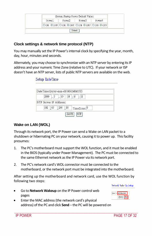
_____________________________________________________________________________
IP POWER PAGE 17 OF 32
Clock settings amp network time protocol (NTP)
You may manually set the IP Powerrsquos internal clock by specifying the year month day hour minutes and seconds
Alternately you may choose to synchronize with an NTP server by entering its IP address and your numeric Time Zone (relative to UTC) If your network or ISP doesnrsquot have an NTP server lists of public NTP servers are available on the web
Wake on LAN (WOL)
Through its network port the IP Power can send a Wake on LAN packet to a shutdown or hibernating PC on your network causing it to power up This facility presumes
1 The PCrsquos motherboard must support the WOL function and it must be enabled in the BIOS (typically under Power Management) The PC must be connected to the same Ethernet network as the IP Power via its network port
2 The PCrsquos network cardrsquos WOL connector must be connected to the motherboard or the network port must be integrated into the motherboard
After setting up the motherboard and network card use the WOL function by following two steps
Go to Network Wakeup on the IP Power control web pages
Enter the MAC address (the network cardrsquos physical address) of the PC and click Send ndash the PC will be powered on
_____________________________________________________________________________
IP POWER PAGE 18 OF 32
NOTE
To find out your network cardrsquos MAC address
Right click on the network connection icon Status Support Details The value in Physical Address is the MAC address
6 Firmware Update
Warning If you have not been advised to update the IP Powerrsquos firmware and do not have a new firmware file please do not go to this page
NOTE Before updating the IP Powerrsquos firmware ensure the IP Power control web pagesrsquo TCP port is set
to 80 (this is the default) otherwise the update may fail
Firmware updates are periodically released to update the functionality of the IP Power To update the IP Powerrsquos firmware select Firmware Update from the left hand menu
The following warning is displayed
_____________________________________________________________________________
IP POWER PAGE 19 OF 32
Warning Do not click Update if you do not have a firmware update file
Click Update the following window is displayed
Click Browse and locate the firmware update file Click Update to begin the update
Note When the update is complete you must wait at least one minute before you restart the IP Power
7 DDNS Settings
When connecting to the Internet the IP address you gain from ISP may be dynamically allocated so it may change each time the Internet connection reconnects This may result in the IP Power becoming uncontactable to remote clients as the new address is unknown Dynamic DNS addresses this issue by updating DNS records whenever the IP address changes The IP Power can utilize the free service provided by DynDNS (httpwwwdyndnscom) for this purpose The IP Power will always be contactable using its DynDNS address (eg ippowerdyndnsorg) regardless of its IP address
_____________________________________________________________________________
IP POWER PAGE 20 OF 32
First create a DynDNS account and create an account Create a dynamic DNS host for the IP Power eg ippowerdyndnsorg On the IP Power select DDNS from the left hand menu Enter the IP address and port of the DynDNS server You can find this out on your PC by selecting Start Run then type in cmd and typing ping wwwdyndnscom Enter the number in brackets (eg 6320819666) followed by 80 to denote the port In Your Domain enter the IP Powerrsquos DynDNS address eg ippowerdyndnsorg Enter the Username and Password for the DynDNS account you created Ensure Enable DDNS is set to TRUE Click Save Now each time the IP Power is powered on or Update Now is clicked the DynDNS address will be updated to the IP Powerrsquos current IP address Note that the change may take several minutes to propagate to your local DNS server If the IP Power cannot reach the DynDNS server without going through a proxy server select TRUE next to Proxy Enable Enter the IP address of the proxy server in Proxy IP and the port in Proxy Port
NOTE
The first time you configure DDNS click Update Now to set the DynDNS address
8 Control Using Telnet HTTP amp SNMP Commands
The IP Power is a principally a browser controlled unit with power control effected over the LAN using HTTP commands or a browser However it also provides alternate methods for directly setting and getting the status of the power outlets through Telnet commands and HTTP commands (which may be useful for controlling the IP Powerrsquos outlets using an automated script) and through SMNP Power outlet status and control using HTTP commands
The format of the HTTP command is
_____________________________________________________________________________
IP POWER PAGE 21 OF 32
httpusernamepasswordabcdSetcmdCMD=command+outlet_id=10+out
let_id=10 Where username The username you use to login to the IP Power (default is admin)
password The password you use to login to the IP Power (default is 12345678)
abcd The IP address of the IP Power (default is 192168050)
command GetPower to read the status (specifying outlets is not required) SetPower to turn on or off the ports (power setting for each outlet must
be specified after the command)
port_id (SetPower only) P60 Port 1 P61 Port 2 P62 Port 3 P63 Port 4 Example 1 The HTTP command httpadmin123456781921680 50SetcmdCMD=GetPower Returns the power status for each outlet in the following format (outlets 5 to 8 may be ignored) lthtmlgtP60=0P61=0P62=0P63=0P64=0P65=0P66=0P67=0lthtmlgt In the above example all outlets are off Example 2 The HTTP command httpadmin12345678192168050SetcmdCMD=SetPower+P60=1+P61=0+P62=0+P63=1
_____________________________________________________________________________
IP POWER PAGE 22 OF 32
Turns the power on for the first (P60) and fourth (P63) outlets and turns power off for the second (P61) and third (P62) outlets Returns the power status for each outlet in the following format lthtmlgtP60=1P61=0P62=0P63=1lthtmlgt Example 3 The HTTP command to control the 9258 operation at a specified time httpusernamepasswordXXXXXXXXXXXXSetcmdCMD=SetSchedule+Power =+YY=+MM=+DD=+HH=+MN=+SS=+PARAM=+ONOFF= Where Control parameters are 1A 1B 2A 2B 3A 3B 4A 4B A = connect power B = disconnect power YY=+MM=+DD=+HH=+MN=+SS= time parameter YY year (20YY) 01 = 2001 MM month (0 1-12) DD date (01-31) HH hour (24 hours 0- 23) MN minute (1-60) SS second (1-60) PARAM= time schedule parameter Parameter list as follows 128 Once only 127 Every day 31 Week days (Monday to Friday) 96 Weekend days (Saturday and Sunday) ONOFF= operate parameter 0 open 1 close For example
_____________________________________________________________________________
IP POWER PAGE 23 OF 32
http admin12345678192168110SetcmdCMD=SetSchedule+Power=1A+YY=2009+MM=02+DD=16+HH=06+MN=02+SS=16+PARAM=128+ONOFF=1 The above command controls the IP Power at IP address 19216810 user name is admin and password is 12345678 This 9258 will connect power of outlet 1 (p60) once only on 16th February 2009 at 602 am
NOTE Use + to separate each parameter eg to simply power on outlet 1 httpadmin12345678192168110SetcmdCMD=SetPower+P60=1
The command syntax is case sensitive so be selective when using upper and lower case in command format The free tool wget is useful for sending these HTTP commands For example
to send the command in Example 1 you could use wget ndashO -httpadmin12345678192168050SetcmdCMD=SetPower+P60=1+P61=0+P62=0+P63=1
Power outlet status and control using Telnet
Under DOS mode type ldquo Cgttelnet [IP9258] ldquo
To log in to the device use the syntax login=password
Typing help will give you the other commands that are available for the 9258 in telnet
_____________________________________________________________________________
IP POWER PAGE 24 OF 32
The getpower command reports the status of power outlets 1-4 The setpower command controls the power outlets 1-4 with ldquo0rdquo turning power off and ldquo1rdquo turning power on Example 1 setpower =11110000 (This will turn on power 1-4) Example 2 setpower =11000000 (This turns on power on 1 amp 2 and turns off power 3 amp 4)
NOTE Only the first four numbers are used You can select from 0 to turn off the power to 1 to turn on the
power However with 155 the syntax requires to use eight separte digits If you only use four digits the command will not work properly
_____________________________________________________________________________
IP POWER PAGE 25 OF 32
Power outlet status and control using SNMP
Reading status
snmpget -v 1 -c public 192168155 1361419258210 (read status of Power1)
snmpget -v 1 -c public 192168155 1361419258220 (read status of Power2) snmpget -v 1 -c public 192168155 1361419258230 (read status of Power3) snmpget -v 1 -c public 192168155 1361419258240 (read status of Power4)
(Return value as ldquoINTEGER 1 rdquo means power ON Return value as ldquoINTEGER 0 rdquo means power OFF)
_____________________________________________________________________________
IP POWER PAGE 26 OF 32
Control outlet command
snmpset -v 1 -c public 192168155 1361419258210 integer 1 (turn on Power1) snmpset -v 1 -c public 192168155 1361419258220 integer 0 (turn off Power2)
snmpset -v 1 -c public 192168155 1361419258230 integer 1 (turn on Power3) snmpset -v 1 -c public 192168155 1361419258240 integer 0 (turn off Power4)
Power cycle outlet command snmpset -v 1 -c public 192168155 1361419258310 integer 1 (powercycle No1)
snmpset -v 1 -c public 192168155 1361419258320 integer 1 (powercycle No2) snmpset -v 1 -c public 192168155 1361419258330 integer 1 (powercycle No3)
_____________________________________________________________________________
IP POWER PAGE 27 OF 32
snmpset -v 1 -c public 192168155 1361419258340 integer 1 (powercycle No4)
If the power is on the outlet will turn ldquoOFF to ON ldquo when the power cycle command is placed However if powered off the outlet will turn ldquoON to OFF to ON ldquo when place power cycle command
9 Frequently Asked Question
Q1 I forgot the password and can not enter the administration page now what can I do A1 Use the username super user when logging in to the webpage and then click OK Turn the IP Power off for a few seconds the turn it back on The default username of admin and password of 12345678 will be restored Note there is a space between super and user
10 Manual Control Mode
The IP Power is generally controlled from a local or remote computer however the outlets can also be controlled manually
NOTE
Before using the manual control function it is necessary to UNPLUG DISCONNECT all of the 4 outlets
To obtain manual control
_____________________________________________________________________________
IP POWER PAGE 28 OF 32
Press and hold the ONOFF button (depicted below) for a full 5 seconds or until a sustained beep noise is heard ndash this enables manual control mode which can be identified by the flashing outlet lights
The outlet light that is not flashing is the one currently under manual control ndash this outlet can be turned on or off by pressing the ONOFF button
To select an alternate outlet to control press the Cycle button (labeled with a circle with arrows on it)
To disable manual control mode press and hold the ONOFF button for 5 seconds or until you can hear a sustained beep noise ndash signifying the deactivation of manual control mode
Cycle (left) Select power outlet to manually control
ONOFF (right) Press and hold to enabledisable manual control mode press to turn onoff the outlet selected by the cycle button
11 IP Power Control Using Console Server
The IP Power 9258 is a simple browser controlled power switch without the security features needed for open public network connection Nor does it have any remote out-of-band dial-in support
However the IP Power can be configured securely and its outlets can be controlled in-band and out of band when used in conjunction with an Opengear console server
Out of band access
The Opengear console server provides secure remoteout-of-band access through a dial in modem (or through an alternate broadband connection) To configure the console server for dial-in access
_____________________________________________________________________________
IP POWER PAGE 29 OF 32
Connect a modem to the consolemodem port and configure the console server for dial-in
The IP Power can then be network or serially connected to the console server
SSH tunneled control through the Console Server
If the IP Power is connected on the remote LAN with the console server then it can be browser controlled
Configure the console server with the IP Power as a HTTP accessible Host This Managed Device can then be remotely controlled securely using SSH tunneling (SDT)
Configure the remote SDTConnector client to access the gateway (console server) and then to connect to the IP Power using HTTP (refer wwwopengearcomfaq267html for details)
Console Server serial control
The IP Power is a principally a browser controlled unit and its RS232 serial port mainly provides diagnostic and status information (eg sending out its IP address and power on messages during Power On Self Test) However the IP Power serial port also supports emergency power control To configure the IP Power for serial control
Connect the IP Power 9258s CONSOLE RS232 port to one of the console server serial ports (for CM4001 2 this interconnection will use a standard UTP Cat 5 cable with a 319000 adapter at each end and all other console servers will only require one 319000 adaptor)
Configured the console server serial port with a serially controlled PDU
_____________________________________________________________________________
IP POWER PAGE 30 OF 32
The IP Power outlets are then controlled by securely (HTTPS) accessing the Manage Power menu on the console server Management Console (refer wwwopengearcomfaq231html for details)
NOTE
The outlet control commands are sent from the console server to the IP Power over the serial port
The combination of out of band access and IP Power serial port control can be particularly useful in managing remote sites where a DSL router (interconnect the office LAN and the internet) may have become dysfunctional requiring a power reset
12 General IP Power Control Using Serial Port
The IP Power RS232 serial port mainly provides diagnostic and status information however the serial port can be used for emergency power control as covered in the previous section
Usage power-ip9258 ltportgt ltoutletgt [outlet] on|off|status
The serial control script below is used in the console server and should work on a normal Linux box
binsh
out_udelay=50000
_____________________________________________________________________________
IP POWER PAGE 31 OF 32
out_retries=3
in_udelay=100000
in_retries=10
port=$1
outlets=$2 cmd=$3 tmpfile=tmptmp$$
if [[ -z $port ]] || [[ -z $outlets ]] || [[ -z $cmd ]] then appname=`basename $0`
echo Usage $appname ltportgt ltoutletgt [outlet] on|off|status exit 1 fi
function ipp_chat () out=$1
in=$2 cat $port gt $tmpfile amp
cat_pid=$ trap rm $tmpfile kill $cat_pid EXIT
for (( i=0 i lt $out_retries i++ )) do for (( j = 0 j lt $out j++ )) do usleep $out_udelay
echo -n $out$j1 gt $port done echo gt $port
for (( j=0 j lt $in_retries j++ )) do usleep $in_udelay line=`grep $in $tmpfile`
if [[ -n $line ]] then break 2 fi
done done
rm $tmpfile kill $cat_pid
if [[ -n $line ]] then echo $line else
echo Command failed ($out) exit 1 fi
Suppress error messages from the shell
exec 2gt devnull Set up the serial port for the IP Power
_____________________________________________________________________________
IP POWER PAGE 32 OF 32
stty 14004cbea3031c7f15401011131a012f17160000000000000
000 lt $port Enable serial command mode
ipp_chat 0ADEBUG9258Z IP9258 DEBUG ON ampgt devnull Get current status
status_nibble=`ipp_chat 0Ap06Z p6 | sed sp6()1g`
Send the command the least significant bit is port 1 the most significant is port 4 A value of 0 is on 1 is off
outlet_mask=0 for o in $outlets do outlet_bit=$(( 1ltlt $o-1 ))
outlet_mask=$(( outlet_mask | $outlet_bit )) done status_nibble=`printf d 0x$status_nibble`
if [[ $cmd == on ]] then echo Powering on outlet $outlets status_nibble=`printf X $(( $status_nibble amp ~$outlet_mask ))`
ipp_chat 0AP06F$status_nibbleZ P6=F$status_nibble ampgt devnull echo Outlet $outlets powered on
elif [[ $cmd == off ]] then echo Powering off outlet $outlets status_nibble=`printf X $(( $status_nibble | $outlet_mask ))`
ipp_chat 0AP06F$status_nibbleZ P6=F$status_nibble ampgt devnull echo Outlet $outlets powered off
else for o in $outlets do outlet_bit=$(( 1ltlt $o-1 ))
echo -n Outlet $o is if [[ $(( $status_nibble amp $outlet_bit )) -eq $outlet_bit ]] then echo off
else echo on fi
done fi
Disable serial command mode ipp_chat 0ADEBUG0FFZ IP9258 DEBUG OFF ampgt devnull exit 0
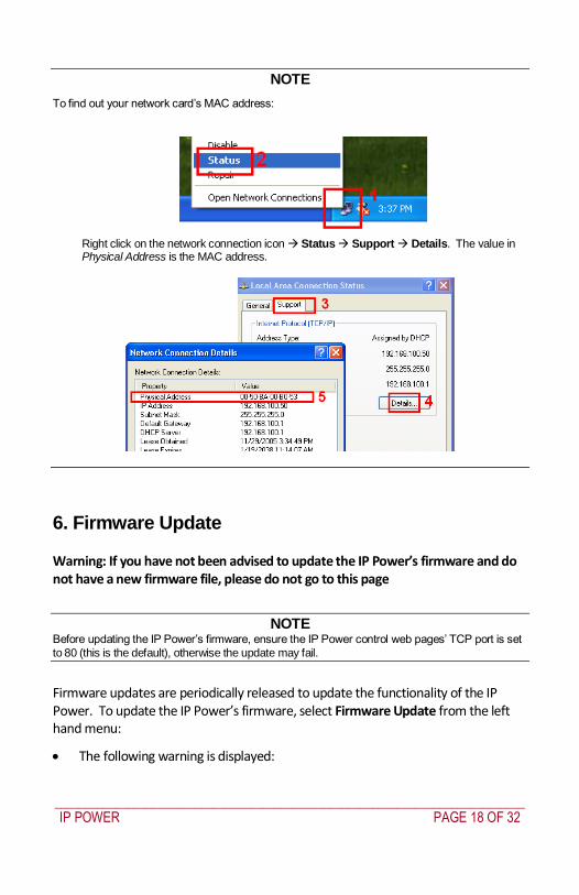
_____________________________________________________________________________
IP POWER PAGE 18 OF 32
NOTE
To find out your network cardrsquos MAC address
Right click on the network connection icon Status Support Details The value in Physical Address is the MAC address
6 Firmware Update
Warning If you have not been advised to update the IP Powerrsquos firmware and do not have a new firmware file please do not go to this page
NOTE Before updating the IP Powerrsquos firmware ensure the IP Power control web pagesrsquo TCP port is set
to 80 (this is the default) otherwise the update may fail
Firmware updates are periodically released to update the functionality of the IP Power To update the IP Powerrsquos firmware select Firmware Update from the left hand menu
The following warning is displayed
_____________________________________________________________________________
IP POWER PAGE 19 OF 32
Warning Do not click Update if you do not have a firmware update file
Click Update the following window is displayed
Click Browse and locate the firmware update file Click Update to begin the update
Note When the update is complete you must wait at least one minute before you restart the IP Power
7 DDNS Settings
When connecting to the Internet the IP address you gain from ISP may be dynamically allocated so it may change each time the Internet connection reconnects This may result in the IP Power becoming uncontactable to remote clients as the new address is unknown Dynamic DNS addresses this issue by updating DNS records whenever the IP address changes The IP Power can utilize the free service provided by DynDNS (httpwwwdyndnscom) for this purpose The IP Power will always be contactable using its DynDNS address (eg ippowerdyndnsorg) regardless of its IP address
_____________________________________________________________________________
IP POWER PAGE 20 OF 32
First create a DynDNS account and create an account Create a dynamic DNS host for the IP Power eg ippowerdyndnsorg On the IP Power select DDNS from the left hand menu Enter the IP address and port of the DynDNS server You can find this out on your PC by selecting Start Run then type in cmd and typing ping wwwdyndnscom Enter the number in brackets (eg 6320819666) followed by 80 to denote the port In Your Domain enter the IP Powerrsquos DynDNS address eg ippowerdyndnsorg Enter the Username and Password for the DynDNS account you created Ensure Enable DDNS is set to TRUE Click Save Now each time the IP Power is powered on or Update Now is clicked the DynDNS address will be updated to the IP Powerrsquos current IP address Note that the change may take several minutes to propagate to your local DNS server If the IP Power cannot reach the DynDNS server without going through a proxy server select TRUE next to Proxy Enable Enter the IP address of the proxy server in Proxy IP and the port in Proxy Port
NOTE
The first time you configure DDNS click Update Now to set the DynDNS address
8 Control Using Telnet HTTP amp SNMP Commands
The IP Power is a principally a browser controlled unit with power control effected over the LAN using HTTP commands or a browser However it also provides alternate methods for directly setting and getting the status of the power outlets through Telnet commands and HTTP commands (which may be useful for controlling the IP Powerrsquos outlets using an automated script) and through SMNP Power outlet status and control using HTTP commands
The format of the HTTP command is
_____________________________________________________________________________
IP POWER PAGE 21 OF 32
httpusernamepasswordabcdSetcmdCMD=command+outlet_id=10+out
let_id=10 Where username The username you use to login to the IP Power (default is admin)
password The password you use to login to the IP Power (default is 12345678)
abcd The IP address of the IP Power (default is 192168050)
command GetPower to read the status (specifying outlets is not required) SetPower to turn on or off the ports (power setting for each outlet must
be specified after the command)
port_id (SetPower only) P60 Port 1 P61 Port 2 P62 Port 3 P63 Port 4 Example 1 The HTTP command httpadmin123456781921680 50SetcmdCMD=GetPower Returns the power status for each outlet in the following format (outlets 5 to 8 may be ignored) lthtmlgtP60=0P61=0P62=0P63=0P64=0P65=0P66=0P67=0lthtmlgt In the above example all outlets are off Example 2 The HTTP command httpadmin12345678192168050SetcmdCMD=SetPower+P60=1+P61=0+P62=0+P63=1
_____________________________________________________________________________
IP POWER PAGE 22 OF 32
Turns the power on for the first (P60) and fourth (P63) outlets and turns power off for the second (P61) and third (P62) outlets Returns the power status for each outlet in the following format lthtmlgtP60=1P61=0P62=0P63=1lthtmlgt Example 3 The HTTP command to control the 9258 operation at a specified time httpusernamepasswordXXXXXXXXXXXXSetcmdCMD=SetSchedule+Power =+YY=+MM=+DD=+HH=+MN=+SS=+PARAM=+ONOFF= Where Control parameters are 1A 1B 2A 2B 3A 3B 4A 4B A = connect power B = disconnect power YY=+MM=+DD=+HH=+MN=+SS= time parameter YY year (20YY) 01 = 2001 MM month (0 1-12) DD date (01-31) HH hour (24 hours 0- 23) MN minute (1-60) SS second (1-60) PARAM= time schedule parameter Parameter list as follows 128 Once only 127 Every day 31 Week days (Monday to Friday) 96 Weekend days (Saturday and Sunday) ONOFF= operate parameter 0 open 1 close For example
_____________________________________________________________________________
IP POWER PAGE 23 OF 32
http admin12345678192168110SetcmdCMD=SetSchedule+Power=1A+YY=2009+MM=02+DD=16+HH=06+MN=02+SS=16+PARAM=128+ONOFF=1 The above command controls the IP Power at IP address 19216810 user name is admin and password is 12345678 This 9258 will connect power of outlet 1 (p60) once only on 16th February 2009 at 602 am
NOTE Use + to separate each parameter eg to simply power on outlet 1 httpadmin12345678192168110SetcmdCMD=SetPower+P60=1
The command syntax is case sensitive so be selective when using upper and lower case in command format The free tool wget is useful for sending these HTTP commands For example
to send the command in Example 1 you could use wget ndashO -httpadmin12345678192168050SetcmdCMD=SetPower+P60=1+P61=0+P62=0+P63=1
Power outlet status and control using Telnet
Under DOS mode type ldquo Cgttelnet [IP9258] ldquo
To log in to the device use the syntax login=password
Typing help will give you the other commands that are available for the 9258 in telnet
_____________________________________________________________________________
IP POWER PAGE 24 OF 32
The getpower command reports the status of power outlets 1-4 The setpower command controls the power outlets 1-4 with ldquo0rdquo turning power off and ldquo1rdquo turning power on Example 1 setpower =11110000 (This will turn on power 1-4) Example 2 setpower =11000000 (This turns on power on 1 amp 2 and turns off power 3 amp 4)
NOTE Only the first four numbers are used You can select from 0 to turn off the power to 1 to turn on the
power However with 155 the syntax requires to use eight separte digits If you only use four digits the command will not work properly
_____________________________________________________________________________
IP POWER PAGE 25 OF 32
Power outlet status and control using SNMP
Reading status
snmpget -v 1 -c public 192168155 1361419258210 (read status of Power1)
snmpget -v 1 -c public 192168155 1361419258220 (read status of Power2) snmpget -v 1 -c public 192168155 1361419258230 (read status of Power3) snmpget -v 1 -c public 192168155 1361419258240 (read status of Power4)
(Return value as ldquoINTEGER 1 rdquo means power ON Return value as ldquoINTEGER 0 rdquo means power OFF)
_____________________________________________________________________________
IP POWER PAGE 26 OF 32
Control outlet command
snmpset -v 1 -c public 192168155 1361419258210 integer 1 (turn on Power1) snmpset -v 1 -c public 192168155 1361419258220 integer 0 (turn off Power2)
snmpset -v 1 -c public 192168155 1361419258230 integer 1 (turn on Power3) snmpset -v 1 -c public 192168155 1361419258240 integer 0 (turn off Power4)
Power cycle outlet command snmpset -v 1 -c public 192168155 1361419258310 integer 1 (powercycle No1)
snmpset -v 1 -c public 192168155 1361419258320 integer 1 (powercycle No2) snmpset -v 1 -c public 192168155 1361419258330 integer 1 (powercycle No3)
_____________________________________________________________________________
IP POWER PAGE 27 OF 32
snmpset -v 1 -c public 192168155 1361419258340 integer 1 (powercycle No4)
If the power is on the outlet will turn ldquoOFF to ON ldquo when the power cycle command is placed However if powered off the outlet will turn ldquoON to OFF to ON ldquo when place power cycle command
9 Frequently Asked Question
Q1 I forgot the password and can not enter the administration page now what can I do A1 Use the username super user when logging in to the webpage and then click OK Turn the IP Power off for a few seconds the turn it back on The default username of admin and password of 12345678 will be restored Note there is a space between super and user
10 Manual Control Mode
The IP Power is generally controlled from a local or remote computer however the outlets can also be controlled manually
NOTE
Before using the manual control function it is necessary to UNPLUG DISCONNECT all of the 4 outlets
To obtain manual control
_____________________________________________________________________________
IP POWER PAGE 28 OF 32
Press and hold the ONOFF button (depicted below) for a full 5 seconds or until a sustained beep noise is heard ndash this enables manual control mode which can be identified by the flashing outlet lights
The outlet light that is not flashing is the one currently under manual control ndash this outlet can be turned on or off by pressing the ONOFF button
To select an alternate outlet to control press the Cycle button (labeled with a circle with arrows on it)
To disable manual control mode press and hold the ONOFF button for 5 seconds or until you can hear a sustained beep noise ndash signifying the deactivation of manual control mode
Cycle (left) Select power outlet to manually control
ONOFF (right) Press and hold to enabledisable manual control mode press to turn onoff the outlet selected by the cycle button
11 IP Power Control Using Console Server
The IP Power 9258 is a simple browser controlled power switch without the security features needed for open public network connection Nor does it have any remote out-of-band dial-in support
However the IP Power can be configured securely and its outlets can be controlled in-band and out of band when used in conjunction with an Opengear console server
Out of band access
The Opengear console server provides secure remoteout-of-band access through a dial in modem (or through an alternate broadband connection) To configure the console server for dial-in access
_____________________________________________________________________________
IP POWER PAGE 29 OF 32
Connect a modem to the consolemodem port and configure the console server for dial-in
The IP Power can then be network or serially connected to the console server
SSH tunneled control through the Console Server
If the IP Power is connected on the remote LAN with the console server then it can be browser controlled
Configure the console server with the IP Power as a HTTP accessible Host This Managed Device can then be remotely controlled securely using SSH tunneling (SDT)
Configure the remote SDTConnector client to access the gateway (console server) and then to connect to the IP Power using HTTP (refer wwwopengearcomfaq267html for details)
Console Server serial control
The IP Power is a principally a browser controlled unit and its RS232 serial port mainly provides diagnostic and status information (eg sending out its IP address and power on messages during Power On Self Test) However the IP Power serial port also supports emergency power control To configure the IP Power for serial control
Connect the IP Power 9258s CONSOLE RS232 port to one of the console server serial ports (for CM4001 2 this interconnection will use a standard UTP Cat 5 cable with a 319000 adapter at each end and all other console servers will only require one 319000 adaptor)
Configured the console server serial port with a serially controlled PDU
_____________________________________________________________________________
IP POWER PAGE 30 OF 32
The IP Power outlets are then controlled by securely (HTTPS) accessing the Manage Power menu on the console server Management Console (refer wwwopengearcomfaq231html for details)
NOTE
The outlet control commands are sent from the console server to the IP Power over the serial port
The combination of out of band access and IP Power serial port control can be particularly useful in managing remote sites where a DSL router (interconnect the office LAN and the internet) may have become dysfunctional requiring a power reset
12 General IP Power Control Using Serial Port
The IP Power RS232 serial port mainly provides diagnostic and status information however the serial port can be used for emergency power control as covered in the previous section
Usage power-ip9258 ltportgt ltoutletgt [outlet] on|off|status
The serial control script below is used in the console server and should work on a normal Linux box
binsh
out_udelay=50000
_____________________________________________________________________________
IP POWER PAGE 31 OF 32
out_retries=3
in_udelay=100000
in_retries=10
port=$1
outlets=$2 cmd=$3 tmpfile=tmptmp$$
if [[ -z $port ]] || [[ -z $outlets ]] || [[ -z $cmd ]] then appname=`basename $0`
echo Usage $appname ltportgt ltoutletgt [outlet] on|off|status exit 1 fi
function ipp_chat () out=$1
in=$2 cat $port gt $tmpfile amp
cat_pid=$ trap rm $tmpfile kill $cat_pid EXIT
for (( i=0 i lt $out_retries i++ )) do for (( j = 0 j lt $out j++ )) do usleep $out_udelay
echo -n $out$j1 gt $port done echo gt $port
for (( j=0 j lt $in_retries j++ )) do usleep $in_udelay line=`grep $in $tmpfile`
if [[ -n $line ]] then break 2 fi
done done
rm $tmpfile kill $cat_pid
if [[ -n $line ]] then echo $line else
echo Command failed ($out) exit 1 fi
Suppress error messages from the shell
exec 2gt devnull Set up the serial port for the IP Power
_____________________________________________________________________________
IP POWER PAGE 32 OF 32
stty 14004cbea3031c7f15401011131a012f17160000000000000
000 lt $port Enable serial command mode
ipp_chat 0ADEBUG9258Z IP9258 DEBUG ON ampgt devnull Get current status
status_nibble=`ipp_chat 0Ap06Z p6 | sed sp6()1g`
Send the command the least significant bit is port 1 the most significant is port 4 A value of 0 is on 1 is off
outlet_mask=0 for o in $outlets do outlet_bit=$(( 1ltlt $o-1 ))
outlet_mask=$(( outlet_mask | $outlet_bit )) done status_nibble=`printf d 0x$status_nibble`
if [[ $cmd == on ]] then echo Powering on outlet $outlets status_nibble=`printf X $(( $status_nibble amp ~$outlet_mask ))`
ipp_chat 0AP06F$status_nibbleZ P6=F$status_nibble ampgt devnull echo Outlet $outlets powered on
elif [[ $cmd == off ]] then echo Powering off outlet $outlets status_nibble=`printf X $(( $status_nibble | $outlet_mask ))`
ipp_chat 0AP06F$status_nibbleZ P6=F$status_nibble ampgt devnull echo Outlet $outlets powered off
else for o in $outlets do outlet_bit=$(( 1ltlt $o-1 ))
echo -n Outlet $o is if [[ $(( $status_nibble amp $outlet_bit )) -eq $outlet_bit ]] then echo off
else echo on fi
done fi
Disable serial command mode ipp_chat 0ADEBUG0FFZ IP9258 DEBUG OFF ampgt devnull exit 0
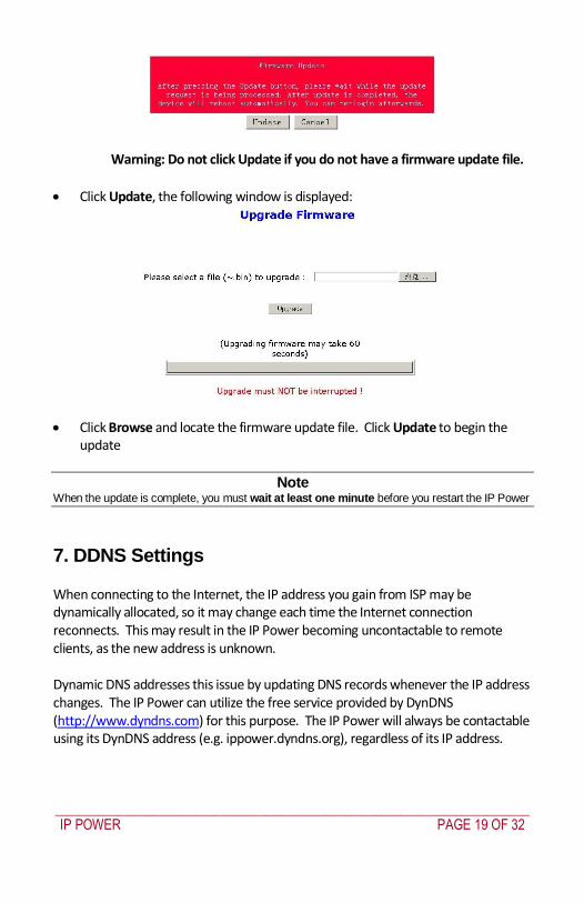
_____________________________________________________________________________
IP POWER PAGE 19 OF 32
Warning Do not click Update if you do not have a firmware update file
Click Update the following window is displayed
Click Browse and locate the firmware update file Click Update to begin the update
Note When the update is complete you must wait at least one minute before you restart the IP Power
7 DDNS Settings
When connecting to the Internet the IP address you gain from ISP may be dynamically allocated so it may change each time the Internet connection reconnects This may result in the IP Power becoming uncontactable to remote clients as the new address is unknown Dynamic DNS addresses this issue by updating DNS records whenever the IP address changes The IP Power can utilize the free service provided by DynDNS (httpwwwdyndnscom) for this purpose The IP Power will always be contactable using its DynDNS address (eg ippowerdyndnsorg) regardless of its IP address
_____________________________________________________________________________
IP POWER PAGE 20 OF 32
First create a DynDNS account and create an account Create a dynamic DNS host for the IP Power eg ippowerdyndnsorg On the IP Power select DDNS from the left hand menu Enter the IP address and port of the DynDNS server You can find this out on your PC by selecting Start Run then type in cmd and typing ping wwwdyndnscom Enter the number in brackets (eg 6320819666) followed by 80 to denote the port In Your Domain enter the IP Powerrsquos DynDNS address eg ippowerdyndnsorg Enter the Username and Password for the DynDNS account you created Ensure Enable DDNS is set to TRUE Click Save Now each time the IP Power is powered on or Update Now is clicked the DynDNS address will be updated to the IP Powerrsquos current IP address Note that the change may take several minutes to propagate to your local DNS server If the IP Power cannot reach the DynDNS server without going through a proxy server select TRUE next to Proxy Enable Enter the IP address of the proxy server in Proxy IP and the port in Proxy Port
NOTE
The first time you configure DDNS click Update Now to set the DynDNS address
8 Control Using Telnet HTTP amp SNMP Commands
The IP Power is a principally a browser controlled unit with power control effected over the LAN using HTTP commands or a browser However it also provides alternate methods for directly setting and getting the status of the power outlets through Telnet commands and HTTP commands (which may be useful for controlling the IP Powerrsquos outlets using an automated script) and through SMNP Power outlet status and control using HTTP commands
The format of the HTTP command is
_____________________________________________________________________________
IP POWER PAGE 21 OF 32
httpusernamepasswordabcdSetcmdCMD=command+outlet_id=10+out
let_id=10 Where username The username you use to login to the IP Power (default is admin)
password The password you use to login to the IP Power (default is 12345678)
abcd The IP address of the IP Power (default is 192168050)
command GetPower to read the status (specifying outlets is not required) SetPower to turn on or off the ports (power setting for each outlet must
be specified after the command)
port_id (SetPower only) P60 Port 1 P61 Port 2 P62 Port 3 P63 Port 4 Example 1 The HTTP command httpadmin123456781921680 50SetcmdCMD=GetPower Returns the power status for each outlet in the following format (outlets 5 to 8 may be ignored) lthtmlgtP60=0P61=0P62=0P63=0P64=0P65=0P66=0P67=0lthtmlgt In the above example all outlets are off Example 2 The HTTP command httpadmin12345678192168050SetcmdCMD=SetPower+P60=1+P61=0+P62=0+P63=1
_____________________________________________________________________________
IP POWER PAGE 22 OF 32
Turns the power on for the first (P60) and fourth (P63) outlets and turns power off for the second (P61) and third (P62) outlets Returns the power status for each outlet in the following format lthtmlgtP60=1P61=0P62=0P63=1lthtmlgt Example 3 The HTTP command to control the 9258 operation at a specified time httpusernamepasswordXXXXXXXXXXXXSetcmdCMD=SetSchedule+Power =+YY=+MM=+DD=+HH=+MN=+SS=+PARAM=+ONOFF= Where Control parameters are 1A 1B 2A 2B 3A 3B 4A 4B A = connect power B = disconnect power YY=+MM=+DD=+HH=+MN=+SS= time parameter YY year (20YY) 01 = 2001 MM month (0 1-12) DD date (01-31) HH hour (24 hours 0- 23) MN minute (1-60) SS second (1-60) PARAM= time schedule parameter Parameter list as follows 128 Once only 127 Every day 31 Week days (Monday to Friday) 96 Weekend days (Saturday and Sunday) ONOFF= operate parameter 0 open 1 close For example
_____________________________________________________________________________
IP POWER PAGE 23 OF 32
http admin12345678192168110SetcmdCMD=SetSchedule+Power=1A+YY=2009+MM=02+DD=16+HH=06+MN=02+SS=16+PARAM=128+ONOFF=1 The above command controls the IP Power at IP address 19216810 user name is admin and password is 12345678 This 9258 will connect power of outlet 1 (p60) once only on 16th February 2009 at 602 am
NOTE Use + to separate each parameter eg to simply power on outlet 1 httpadmin12345678192168110SetcmdCMD=SetPower+P60=1
The command syntax is case sensitive so be selective when using upper and lower case in command format The free tool wget is useful for sending these HTTP commands For example
to send the command in Example 1 you could use wget ndashO -httpadmin12345678192168050SetcmdCMD=SetPower+P60=1+P61=0+P62=0+P63=1
Power outlet status and control using Telnet
Under DOS mode type ldquo Cgttelnet [IP9258] ldquo
To log in to the device use the syntax login=password
Typing help will give you the other commands that are available for the 9258 in telnet
_____________________________________________________________________________
IP POWER PAGE 24 OF 32
The getpower command reports the status of power outlets 1-4 The setpower command controls the power outlets 1-4 with ldquo0rdquo turning power off and ldquo1rdquo turning power on Example 1 setpower =11110000 (This will turn on power 1-4) Example 2 setpower =11000000 (This turns on power on 1 amp 2 and turns off power 3 amp 4)
NOTE Only the first four numbers are used You can select from 0 to turn off the power to 1 to turn on the
power However with 155 the syntax requires to use eight separte digits If you only use four digits the command will not work properly
_____________________________________________________________________________
IP POWER PAGE 25 OF 32
Power outlet status and control using SNMP
Reading status
snmpget -v 1 -c public 192168155 1361419258210 (read status of Power1)
snmpget -v 1 -c public 192168155 1361419258220 (read status of Power2) snmpget -v 1 -c public 192168155 1361419258230 (read status of Power3) snmpget -v 1 -c public 192168155 1361419258240 (read status of Power4)
(Return value as ldquoINTEGER 1 rdquo means power ON Return value as ldquoINTEGER 0 rdquo means power OFF)
_____________________________________________________________________________
IP POWER PAGE 26 OF 32
Control outlet command
snmpset -v 1 -c public 192168155 1361419258210 integer 1 (turn on Power1) snmpset -v 1 -c public 192168155 1361419258220 integer 0 (turn off Power2)
snmpset -v 1 -c public 192168155 1361419258230 integer 1 (turn on Power3) snmpset -v 1 -c public 192168155 1361419258240 integer 0 (turn off Power4)
Power cycle outlet command snmpset -v 1 -c public 192168155 1361419258310 integer 1 (powercycle No1)
snmpset -v 1 -c public 192168155 1361419258320 integer 1 (powercycle No2) snmpset -v 1 -c public 192168155 1361419258330 integer 1 (powercycle No3)
_____________________________________________________________________________
IP POWER PAGE 27 OF 32
snmpset -v 1 -c public 192168155 1361419258340 integer 1 (powercycle No4)
If the power is on the outlet will turn ldquoOFF to ON ldquo when the power cycle command is placed However if powered off the outlet will turn ldquoON to OFF to ON ldquo when place power cycle command
9 Frequently Asked Question
Q1 I forgot the password and can not enter the administration page now what can I do A1 Use the username super user when logging in to the webpage and then click OK Turn the IP Power off for a few seconds the turn it back on The default username of admin and password of 12345678 will be restored Note there is a space between super and user
10 Manual Control Mode
The IP Power is generally controlled from a local or remote computer however the outlets can also be controlled manually
NOTE
Before using the manual control function it is necessary to UNPLUG DISCONNECT all of the 4 outlets
To obtain manual control
_____________________________________________________________________________
IP POWER PAGE 28 OF 32
Press and hold the ONOFF button (depicted below) for a full 5 seconds or until a sustained beep noise is heard ndash this enables manual control mode which can be identified by the flashing outlet lights
The outlet light that is not flashing is the one currently under manual control ndash this outlet can be turned on or off by pressing the ONOFF button
To select an alternate outlet to control press the Cycle button (labeled with a circle with arrows on it)
To disable manual control mode press and hold the ONOFF button for 5 seconds or until you can hear a sustained beep noise ndash signifying the deactivation of manual control mode
Cycle (left) Select power outlet to manually control
ONOFF (right) Press and hold to enabledisable manual control mode press to turn onoff the outlet selected by the cycle button
11 IP Power Control Using Console Server
The IP Power 9258 is a simple browser controlled power switch without the security features needed for open public network connection Nor does it have any remote out-of-band dial-in support
However the IP Power can be configured securely and its outlets can be controlled in-band and out of band when used in conjunction with an Opengear console server
Out of band access
The Opengear console server provides secure remoteout-of-band access through a dial in modem (or through an alternate broadband connection) To configure the console server for dial-in access
_____________________________________________________________________________
IP POWER PAGE 29 OF 32
Connect a modem to the consolemodem port and configure the console server for dial-in
The IP Power can then be network or serially connected to the console server
SSH tunneled control through the Console Server
If the IP Power is connected on the remote LAN with the console server then it can be browser controlled
Configure the console server with the IP Power as a HTTP accessible Host This Managed Device can then be remotely controlled securely using SSH tunneling (SDT)
Configure the remote SDTConnector client to access the gateway (console server) and then to connect to the IP Power using HTTP (refer wwwopengearcomfaq267html for details)
Console Server serial control
The IP Power is a principally a browser controlled unit and its RS232 serial port mainly provides diagnostic and status information (eg sending out its IP address and power on messages during Power On Self Test) However the IP Power serial port also supports emergency power control To configure the IP Power for serial control
Connect the IP Power 9258s CONSOLE RS232 port to one of the console server serial ports (for CM4001 2 this interconnection will use a standard UTP Cat 5 cable with a 319000 adapter at each end and all other console servers will only require one 319000 adaptor)
Configured the console server serial port with a serially controlled PDU
_____________________________________________________________________________
IP POWER PAGE 30 OF 32
The IP Power outlets are then controlled by securely (HTTPS) accessing the Manage Power menu on the console server Management Console (refer wwwopengearcomfaq231html for details)
NOTE
The outlet control commands are sent from the console server to the IP Power over the serial port
The combination of out of band access and IP Power serial port control can be particularly useful in managing remote sites where a DSL router (interconnect the office LAN and the internet) may have become dysfunctional requiring a power reset
12 General IP Power Control Using Serial Port
The IP Power RS232 serial port mainly provides diagnostic and status information however the serial port can be used for emergency power control as covered in the previous section
Usage power-ip9258 ltportgt ltoutletgt [outlet] on|off|status
The serial control script below is used in the console server and should work on a normal Linux box
binsh
out_udelay=50000
_____________________________________________________________________________
IP POWER PAGE 31 OF 32
out_retries=3
in_udelay=100000
in_retries=10
port=$1
outlets=$2 cmd=$3 tmpfile=tmptmp$$
if [[ -z $port ]] || [[ -z $outlets ]] || [[ -z $cmd ]] then appname=`basename $0`
echo Usage $appname ltportgt ltoutletgt [outlet] on|off|status exit 1 fi
function ipp_chat () out=$1
in=$2 cat $port gt $tmpfile amp
cat_pid=$ trap rm $tmpfile kill $cat_pid EXIT
for (( i=0 i lt $out_retries i++ )) do for (( j = 0 j lt $out j++ )) do usleep $out_udelay
echo -n $out$j1 gt $port done echo gt $port
for (( j=0 j lt $in_retries j++ )) do usleep $in_udelay line=`grep $in $tmpfile`
if [[ -n $line ]] then break 2 fi
done done
rm $tmpfile kill $cat_pid
if [[ -n $line ]] then echo $line else
echo Command failed ($out) exit 1 fi
Suppress error messages from the shell
exec 2gt devnull Set up the serial port for the IP Power
_____________________________________________________________________________
IP POWER PAGE 32 OF 32
stty 14004cbea3031c7f15401011131a012f17160000000000000
000 lt $port Enable serial command mode
ipp_chat 0ADEBUG9258Z IP9258 DEBUG ON ampgt devnull Get current status
status_nibble=`ipp_chat 0Ap06Z p6 | sed sp6()1g`
Send the command the least significant bit is port 1 the most significant is port 4 A value of 0 is on 1 is off
outlet_mask=0 for o in $outlets do outlet_bit=$(( 1ltlt $o-1 ))
outlet_mask=$(( outlet_mask | $outlet_bit )) done status_nibble=`printf d 0x$status_nibble`
if [[ $cmd == on ]] then echo Powering on outlet $outlets status_nibble=`printf X $(( $status_nibble amp ~$outlet_mask ))`
ipp_chat 0AP06F$status_nibbleZ P6=F$status_nibble ampgt devnull echo Outlet $outlets powered on
elif [[ $cmd == off ]] then echo Powering off outlet $outlets status_nibble=`printf X $(( $status_nibble | $outlet_mask ))`
ipp_chat 0AP06F$status_nibbleZ P6=F$status_nibble ampgt devnull echo Outlet $outlets powered off
else for o in $outlets do outlet_bit=$(( 1ltlt $o-1 ))
echo -n Outlet $o is if [[ $(( $status_nibble amp $outlet_bit )) -eq $outlet_bit ]] then echo off
else echo on fi
done fi
Disable serial command mode ipp_chat 0ADEBUG0FFZ IP9258 DEBUG OFF ampgt devnull exit 0
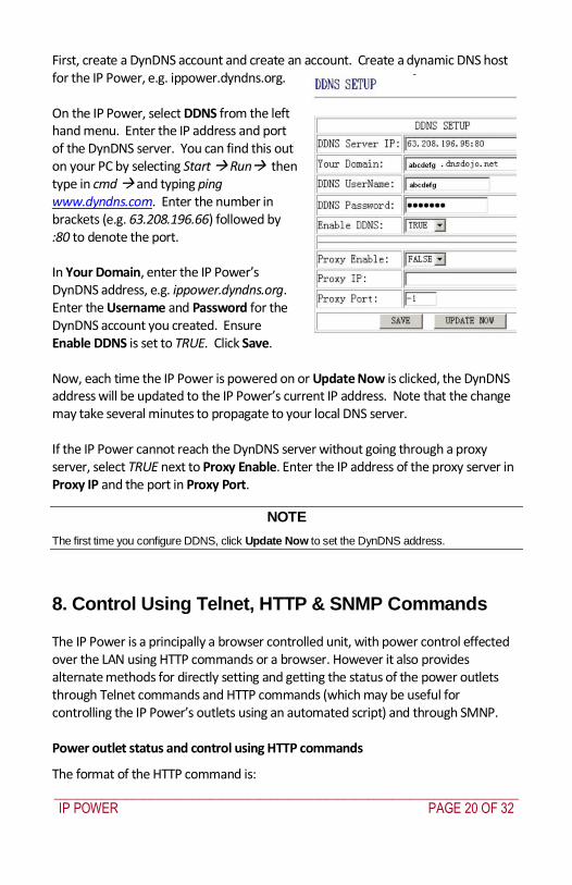
_____________________________________________________________________________
IP POWER PAGE 20 OF 32
First create a DynDNS account and create an account Create a dynamic DNS host for the IP Power eg ippowerdyndnsorg On the IP Power select DDNS from the left hand menu Enter the IP address and port of the DynDNS server You can find this out on your PC by selecting Start Run then type in cmd and typing ping wwwdyndnscom Enter the number in brackets (eg 6320819666) followed by 80 to denote the port In Your Domain enter the IP Powerrsquos DynDNS address eg ippowerdyndnsorg Enter the Username and Password for the DynDNS account you created Ensure Enable DDNS is set to TRUE Click Save Now each time the IP Power is powered on or Update Now is clicked the DynDNS address will be updated to the IP Powerrsquos current IP address Note that the change may take several minutes to propagate to your local DNS server If the IP Power cannot reach the DynDNS server without going through a proxy server select TRUE next to Proxy Enable Enter the IP address of the proxy server in Proxy IP and the port in Proxy Port
NOTE
The first time you configure DDNS click Update Now to set the DynDNS address
8 Control Using Telnet HTTP amp SNMP Commands
The IP Power is a principally a browser controlled unit with power control effected over the LAN using HTTP commands or a browser However it also provides alternate methods for directly setting and getting the status of the power outlets through Telnet commands and HTTP commands (which may be useful for controlling the IP Powerrsquos outlets using an automated script) and through SMNP Power outlet status and control using HTTP commands
The format of the HTTP command is
_____________________________________________________________________________
IP POWER PAGE 21 OF 32
httpusernamepasswordabcdSetcmdCMD=command+outlet_id=10+out
let_id=10 Where username The username you use to login to the IP Power (default is admin)
password The password you use to login to the IP Power (default is 12345678)
abcd The IP address of the IP Power (default is 192168050)
command GetPower to read the status (specifying outlets is not required) SetPower to turn on or off the ports (power setting for each outlet must
be specified after the command)
port_id (SetPower only) P60 Port 1 P61 Port 2 P62 Port 3 P63 Port 4 Example 1 The HTTP command httpadmin123456781921680 50SetcmdCMD=GetPower Returns the power status for each outlet in the following format (outlets 5 to 8 may be ignored) lthtmlgtP60=0P61=0P62=0P63=0P64=0P65=0P66=0P67=0lthtmlgt In the above example all outlets are off Example 2 The HTTP command httpadmin12345678192168050SetcmdCMD=SetPower+P60=1+P61=0+P62=0+P63=1
_____________________________________________________________________________
IP POWER PAGE 22 OF 32
Turns the power on for the first (P60) and fourth (P63) outlets and turns power off for the second (P61) and third (P62) outlets Returns the power status for each outlet in the following format lthtmlgtP60=1P61=0P62=0P63=1lthtmlgt Example 3 The HTTP command to control the 9258 operation at a specified time httpusernamepasswordXXXXXXXXXXXXSetcmdCMD=SetSchedule+Power =+YY=+MM=+DD=+HH=+MN=+SS=+PARAM=+ONOFF= Where Control parameters are 1A 1B 2A 2B 3A 3B 4A 4B A = connect power B = disconnect power YY=+MM=+DD=+HH=+MN=+SS= time parameter YY year (20YY) 01 = 2001 MM month (0 1-12) DD date (01-31) HH hour (24 hours 0- 23) MN minute (1-60) SS second (1-60) PARAM= time schedule parameter Parameter list as follows 128 Once only 127 Every day 31 Week days (Monday to Friday) 96 Weekend days (Saturday and Sunday) ONOFF= operate parameter 0 open 1 close For example
_____________________________________________________________________________
IP POWER PAGE 23 OF 32
http admin12345678192168110SetcmdCMD=SetSchedule+Power=1A+YY=2009+MM=02+DD=16+HH=06+MN=02+SS=16+PARAM=128+ONOFF=1 The above command controls the IP Power at IP address 19216810 user name is admin and password is 12345678 This 9258 will connect power of outlet 1 (p60) once only on 16th February 2009 at 602 am
NOTE Use + to separate each parameter eg to simply power on outlet 1 httpadmin12345678192168110SetcmdCMD=SetPower+P60=1
The command syntax is case sensitive so be selective when using upper and lower case in command format The free tool wget is useful for sending these HTTP commands For example
to send the command in Example 1 you could use wget ndashO -httpadmin12345678192168050SetcmdCMD=SetPower+P60=1+P61=0+P62=0+P63=1
Power outlet status and control using Telnet
Under DOS mode type ldquo Cgttelnet [IP9258] ldquo
To log in to the device use the syntax login=password
Typing help will give you the other commands that are available for the 9258 in telnet
_____________________________________________________________________________
IP POWER PAGE 24 OF 32
The getpower command reports the status of power outlets 1-4 The setpower command controls the power outlets 1-4 with ldquo0rdquo turning power off and ldquo1rdquo turning power on Example 1 setpower =11110000 (This will turn on power 1-4) Example 2 setpower =11000000 (This turns on power on 1 amp 2 and turns off power 3 amp 4)
NOTE Only the first four numbers are used You can select from 0 to turn off the power to 1 to turn on the
power However with 155 the syntax requires to use eight separte digits If you only use four digits the command will not work properly
_____________________________________________________________________________
IP POWER PAGE 25 OF 32
Power outlet status and control using SNMP
Reading status
snmpget -v 1 -c public 192168155 1361419258210 (read status of Power1)
snmpget -v 1 -c public 192168155 1361419258220 (read status of Power2) snmpget -v 1 -c public 192168155 1361419258230 (read status of Power3) snmpget -v 1 -c public 192168155 1361419258240 (read status of Power4)
(Return value as ldquoINTEGER 1 rdquo means power ON Return value as ldquoINTEGER 0 rdquo means power OFF)
_____________________________________________________________________________
IP POWER PAGE 26 OF 32
Control outlet command
snmpset -v 1 -c public 192168155 1361419258210 integer 1 (turn on Power1) snmpset -v 1 -c public 192168155 1361419258220 integer 0 (turn off Power2)
snmpset -v 1 -c public 192168155 1361419258230 integer 1 (turn on Power3) snmpset -v 1 -c public 192168155 1361419258240 integer 0 (turn off Power4)
Power cycle outlet command snmpset -v 1 -c public 192168155 1361419258310 integer 1 (powercycle No1)
snmpset -v 1 -c public 192168155 1361419258320 integer 1 (powercycle No2) snmpset -v 1 -c public 192168155 1361419258330 integer 1 (powercycle No3)
_____________________________________________________________________________
IP POWER PAGE 27 OF 32
snmpset -v 1 -c public 192168155 1361419258340 integer 1 (powercycle No4)
If the power is on the outlet will turn ldquoOFF to ON ldquo when the power cycle command is placed However if powered off the outlet will turn ldquoON to OFF to ON ldquo when place power cycle command
9 Frequently Asked Question
Q1 I forgot the password and can not enter the administration page now what can I do A1 Use the username super user when logging in to the webpage and then click OK Turn the IP Power off for a few seconds the turn it back on The default username of admin and password of 12345678 will be restored Note there is a space between super and user
10 Manual Control Mode
The IP Power is generally controlled from a local or remote computer however the outlets can also be controlled manually
NOTE
Before using the manual control function it is necessary to UNPLUG DISCONNECT all of the 4 outlets
To obtain manual control
_____________________________________________________________________________
IP POWER PAGE 28 OF 32
Press and hold the ONOFF button (depicted below) for a full 5 seconds or until a sustained beep noise is heard ndash this enables manual control mode which can be identified by the flashing outlet lights
The outlet light that is not flashing is the one currently under manual control ndash this outlet can be turned on or off by pressing the ONOFF button
To select an alternate outlet to control press the Cycle button (labeled with a circle with arrows on it)
To disable manual control mode press and hold the ONOFF button for 5 seconds or until you can hear a sustained beep noise ndash signifying the deactivation of manual control mode
Cycle (left) Select power outlet to manually control
ONOFF (right) Press and hold to enabledisable manual control mode press to turn onoff the outlet selected by the cycle button
11 IP Power Control Using Console Server
The IP Power 9258 is a simple browser controlled power switch without the security features needed for open public network connection Nor does it have any remote out-of-band dial-in support
However the IP Power can be configured securely and its outlets can be controlled in-band and out of band when used in conjunction with an Opengear console server
Out of band access
The Opengear console server provides secure remoteout-of-band access through a dial in modem (or through an alternate broadband connection) To configure the console server for dial-in access
_____________________________________________________________________________
IP POWER PAGE 29 OF 32
Connect a modem to the consolemodem port and configure the console server for dial-in
The IP Power can then be network or serially connected to the console server
SSH tunneled control through the Console Server
If the IP Power is connected on the remote LAN with the console server then it can be browser controlled
Configure the console server with the IP Power as a HTTP accessible Host This Managed Device can then be remotely controlled securely using SSH tunneling (SDT)
Configure the remote SDTConnector client to access the gateway (console server) and then to connect to the IP Power using HTTP (refer wwwopengearcomfaq267html for details)
Console Server serial control
The IP Power is a principally a browser controlled unit and its RS232 serial port mainly provides diagnostic and status information (eg sending out its IP address and power on messages during Power On Self Test) However the IP Power serial port also supports emergency power control To configure the IP Power for serial control
Connect the IP Power 9258s CONSOLE RS232 port to one of the console server serial ports (for CM4001 2 this interconnection will use a standard UTP Cat 5 cable with a 319000 adapter at each end and all other console servers will only require one 319000 adaptor)
Configured the console server serial port with a serially controlled PDU
_____________________________________________________________________________
IP POWER PAGE 30 OF 32
The IP Power outlets are then controlled by securely (HTTPS) accessing the Manage Power menu on the console server Management Console (refer wwwopengearcomfaq231html for details)
NOTE
The outlet control commands are sent from the console server to the IP Power over the serial port
The combination of out of band access and IP Power serial port control can be particularly useful in managing remote sites where a DSL router (interconnect the office LAN and the internet) may have become dysfunctional requiring a power reset
12 General IP Power Control Using Serial Port
The IP Power RS232 serial port mainly provides diagnostic and status information however the serial port can be used for emergency power control as covered in the previous section
Usage power-ip9258 ltportgt ltoutletgt [outlet] on|off|status
The serial control script below is used in the console server and should work on a normal Linux box
binsh
out_udelay=50000
_____________________________________________________________________________
IP POWER PAGE 31 OF 32
out_retries=3
in_udelay=100000
in_retries=10
port=$1
outlets=$2 cmd=$3 tmpfile=tmptmp$$
if [[ -z $port ]] || [[ -z $outlets ]] || [[ -z $cmd ]] then appname=`basename $0`
echo Usage $appname ltportgt ltoutletgt [outlet] on|off|status exit 1 fi
function ipp_chat () out=$1
in=$2 cat $port gt $tmpfile amp
cat_pid=$ trap rm $tmpfile kill $cat_pid EXIT
for (( i=0 i lt $out_retries i++ )) do for (( j = 0 j lt $out j++ )) do usleep $out_udelay
echo -n $out$j1 gt $port done echo gt $port
for (( j=0 j lt $in_retries j++ )) do usleep $in_udelay line=`grep $in $tmpfile`
if [[ -n $line ]] then break 2 fi
done done
rm $tmpfile kill $cat_pid
if [[ -n $line ]] then echo $line else
echo Command failed ($out) exit 1 fi
Suppress error messages from the shell
exec 2gt devnull Set up the serial port for the IP Power
_____________________________________________________________________________
IP POWER PAGE 32 OF 32
stty 14004cbea3031c7f15401011131a012f17160000000000000
000 lt $port Enable serial command mode
ipp_chat 0ADEBUG9258Z IP9258 DEBUG ON ampgt devnull Get current status
status_nibble=`ipp_chat 0Ap06Z p6 | sed sp6()1g`
Send the command the least significant bit is port 1 the most significant is port 4 A value of 0 is on 1 is off
outlet_mask=0 for o in $outlets do outlet_bit=$(( 1ltlt $o-1 ))
outlet_mask=$(( outlet_mask | $outlet_bit )) done status_nibble=`printf d 0x$status_nibble`
if [[ $cmd == on ]] then echo Powering on outlet $outlets status_nibble=`printf X $(( $status_nibble amp ~$outlet_mask ))`
ipp_chat 0AP06F$status_nibbleZ P6=F$status_nibble ampgt devnull echo Outlet $outlets powered on
elif [[ $cmd == off ]] then echo Powering off outlet $outlets status_nibble=`printf X $(( $status_nibble | $outlet_mask ))`
ipp_chat 0AP06F$status_nibbleZ P6=F$status_nibble ampgt devnull echo Outlet $outlets powered off
else for o in $outlets do outlet_bit=$(( 1ltlt $o-1 ))
echo -n Outlet $o is if [[ $(( $status_nibble amp $outlet_bit )) -eq $outlet_bit ]] then echo off
else echo on fi
done fi
Disable serial command mode ipp_chat 0ADEBUG0FFZ IP9258 DEBUG OFF ampgt devnull exit 0
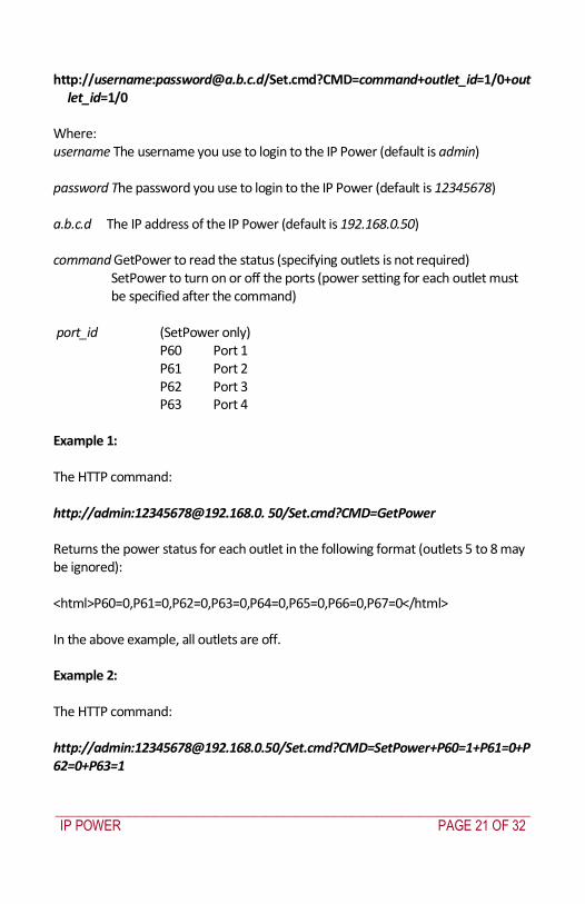
_____________________________________________________________________________
IP POWER PAGE 21 OF 32
httpusernamepasswordabcdSetcmdCMD=command+outlet_id=10+out
let_id=10 Where username The username you use to login to the IP Power (default is admin)
password The password you use to login to the IP Power (default is 12345678)
abcd The IP address of the IP Power (default is 192168050)
command GetPower to read the status (specifying outlets is not required) SetPower to turn on or off the ports (power setting for each outlet must
be specified after the command)
port_id (SetPower only) P60 Port 1 P61 Port 2 P62 Port 3 P63 Port 4 Example 1 The HTTP command httpadmin123456781921680 50SetcmdCMD=GetPower Returns the power status for each outlet in the following format (outlets 5 to 8 may be ignored) lthtmlgtP60=0P61=0P62=0P63=0P64=0P65=0P66=0P67=0lthtmlgt In the above example all outlets are off Example 2 The HTTP command httpadmin12345678192168050SetcmdCMD=SetPower+P60=1+P61=0+P62=0+P63=1
_____________________________________________________________________________
IP POWER PAGE 22 OF 32
Turns the power on for the first (P60) and fourth (P63) outlets and turns power off for the second (P61) and third (P62) outlets Returns the power status for each outlet in the following format lthtmlgtP60=1P61=0P62=0P63=1lthtmlgt Example 3 The HTTP command to control the 9258 operation at a specified time httpusernamepasswordXXXXXXXXXXXXSetcmdCMD=SetSchedule+Power =+YY=+MM=+DD=+HH=+MN=+SS=+PARAM=+ONOFF= Where Control parameters are 1A 1B 2A 2B 3A 3B 4A 4B A = connect power B = disconnect power YY=+MM=+DD=+HH=+MN=+SS= time parameter YY year (20YY) 01 = 2001 MM month (0 1-12) DD date (01-31) HH hour (24 hours 0- 23) MN minute (1-60) SS second (1-60) PARAM= time schedule parameter Parameter list as follows 128 Once only 127 Every day 31 Week days (Monday to Friday) 96 Weekend days (Saturday and Sunday) ONOFF= operate parameter 0 open 1 close For example
_____________________________________________________________________________
IP POWER PAGE 23 OF 32
http admin12345678192168110SetcmdCMD=SetSchedule+Power=1A+YY=2009+MM=02+DD=16+HH=06+MN=02+SS=16+PARAM=128+ONOFF=1 The above command controls the IP Power at IP address 19216810 user name is admin and password is 12345678 This 9258 will connect power of outlet 1 (p60) once only on 16th February 2009 at 602 am
NOTE Use + to separate each parameter eg to simply power on outlet 1 httpadmin12345678192168110SetcmdCMD=SetPower+P60=1
The command syntax is case sensitive so be selective when using upper and lower case in command format The free tool wget is useful for sending these HTTP commands For example
to send the command in Example 1 you could use wget ndashO -httpadmin12345678192168050SetcmdCMD=SetPower+P60=1+P61=0+P62=0+P63=1
Power outlet status and control using Telnet
Under DOS mode type ldquo Cgttelnet [IP9258] ldquo
To log in to the device use the syntax login=password
Typing help will give you the other commands that are available for the 9258 in telnet
_____________________________________________________________________________
IP POWER PAGE 24 OF 32
The getpower command reports the status of power outlets 1-4 The setpower command controls the power outlets 1-4 with ldquo0rdquo turning power off and ldquo1rdquo turning power on Example 1 setpower =11110000 (This will turn on power 1-4) Example 2 setpower =11000000 (This turns on power on 1 amp 2 and turns off power 3 amp 4)
NOTE Only the first four numbers are used You can select from 0 to turn off the power to 1 to turn on the
power However with 155 the syntax requires to use eight separte digits If you only use four digits the command will not work properly
_____________________________________________________________________________
IP POWER PAGE 25 OF 32
Power outlet status and control using SNMP
Reading status
snmpget -v 1 -c public 192168155 1361419258210 (read status of Power1)
snmpget -v 1 -c public 192168155 1361419258220 (read status of Power2) snmpget -v 1 -c public 192168155 1361419258230 (read status of Power3) snmpget -v 1 -c public 192168155 1361419258240 (read status of Power4)
(Return value as ldquoINTEGER 1 rdquo means power ON Return value as ldquoINTEGER 0 rdquo means power OFF)
_____________________________________________________________________________
IP POWER PAGE 26 OF 32
Control outlet command
snmpset -v 1 -c public 192168155 1361419258210 integer 1 (turn on Power1) snmpset -v 1 -c public 192168155 1361419258220 integer 0 (turn off Power2)
snmpset -v 1 -c public 192168155 1361419258230 integer 1 (turn on Power3) snmpset -v 1 -c public 192168155 1361419258240 integer 0 (turn off Power4)
Power cycle outlet command snmpset -v 1 -c public 192168155 1361419258310 integer 1 (powercycle No1)
snmpset -v 1 -c public 192168155 1361419258320 integer 1 (powercycle No2) snmpset -v 1 -c public 192168155 1361419258330 integer 1 (powercycle No3)
_____________________________________________________________________________
IP POWER PAGE 27 OF 32
snmpset -v 1 -c public 192168155 1361419258340 integer 1 (powercycle No4)
If the power is on the outlet will turn ldquoOFF to ON ldquo when the power cycle command is placed However if powered off the outlet will turn ldquoON to OFF to ON ldquo when place power cycle command
9 Frequently Asked Question
Q1 I forgot the password and can not enter the administration page now what can I do A1 Use the username super user when logging in to the webpage and then click OK Turn the IP Power off for a few seconds the turn it back on The default username of admin and password of 12345678 will be restored Note there is a space between super and user
10 Manual Control Mode
The IP Power is generally controlled from a local or remote computer however the outlets can also be controlled manually
NOTE
Before using the manual control function it is necessary to UNPLUG DISCONNECT all of the 4 outlets
To obtain manual control
_____________________________________________________________________________
IP POWER PAGE 28 OF 32
Press and hold the ONOFF button (depicted below) for a full 5 seconds or until a sustained beep noise is heard ndash this enables manual control mode which can be identified by the flashing outlet lights
The outlet light that is not flashing is the one currently under manual control ndash this outlet can be turned on or off by pressing the ONOFF button
To select an alternate outlet to control press the Cycle button (labeled with a circle with arrows on it)
To disable manual control mode press and hold the ONOFF button for 5 seconds or until you can hear a sustained beep noise ndash signifying the deactivation of manual control mode
Cycle (left) Select power outlet to manually control
ONOFF (right) Press and hold to enabledisable manual control mode press to turn onoff the outlet selected by the cycle button
11 IP Power Control Using Console Server
The IP Power 9258 is a simple browser controlled power switch without the security features needed for open public network connection Nor does it have any remote out-of-band dial-in support
However the IP Power can be configured securely and its outlets can be controlled in-band and out of band when used in conjunction with an Opengear console server
Out of band access
The Opengear console server provides secure remoteout-of-band access through a dial in modem (or through an alternate broadband connection) To configure the console server for dial-in access
_____________________________________________________________________________
IP POWER PAGE 29 OF 32
Connect a modem to the consolemodem port and configure the console server for dial-in
The IP Power can then be network or serially connected to the console server
SSH tunneled control through the Console Server
If the IP Power is connected on the remote LAN with the console server then it can be browser controlled
Configure the console server with the IP Power as a HTTP accessible Host This Managed Device can then be remotely controlled securely using SSH tunneling (SDT)
Configure the remote SDTConnector client to access the gateway (console server) and then to connect to the IP Power using HTTP (refer wwwopengearcomfaq267html for details)
Console Server serial control
The IP Power is a principally a browser controlled unit and its RS232 serial port mainly provides diagnostic and status information (eg sending out its IP address and power on messages during Power On Self Test) However the IP Power serial port also supports emergency power control To configure the IP Power for serial control
Connect the IP Power 9258s CONSOLE RS232 port to one of the console server serial ports (for CM4001 2 this interconnection will use a standard UTP Cat 5 cable with a 319000 adapter at each end and all other console servers will only require one 319000 adaptor)
Configured the console server serial port with a serially controlled PDU
_____________________________________________________________________________
IP POWER PAGE 30 OF 32
The IP Power outlets are then controlled by securely (HTTPS) accessing the Manage Power menu on the console server Management Console (refer wwwopengearcomfaq231html for details)
NOTE
The outlet control commands are sent from the console server to the IP Power over the serial port
The combination of out of band access and IP Power serial port control can be particularly useful in managing remote sites where a DSL router (interconnect the office LAN and the internet) may have become dysfunctional requiring a power reset
12 General IP Power Control Using Serial Port
The IP Power RS232 serial port mainly provides diagnostic and status information however the serial port can be used for emergency power control as covered in the previous section
Usage power-ip9258 ltportgt ltoutletgt [outlet] on|off|status
The serial control script below is used in the console server and should work on a normal Linux box
binsh
out_udelay=50000
_____________________________________________________________________________
IP POWER PAGE 31 OF 32
out_retries=3
in_udelay=100000
in_retries=10
port=$1
outlets=$2 cmd=$3 tmpfile=tmptmp$$
if [[ -z $port ]] || [[ -z $outlets ]] || [[ -z $cmd ]] then appname=`basename $0`
echo Usage $appname ltportgt ltoutletgt [outlet] on|off|status exit 1 fi
function ipp_chat () out=$1
in=$2 cat $port gt $tmpfile amp
cat_pid=$ trap rm $tmpfile kill $cat_pid EXIT
for (( i=0 i lt $out_retries i++ )) do for (( j = 0 j lt $out j++ )) do usleep $out_udelay
echo -n $out$j1 gt $port done echo gt $port
for (( j=0 j lt $in_retries j++ )) do usleep $in_udelay line=`grep $in $tmpfile`
if [[ -n $line ]] then break 2 fi
done done
rm $tmpfile kill $cat_pid
if [[ -n $line ]] then echo $line else
echo Command failed ($out) exit 1 fi
Suppress error messages from the shell
exec 2gt devnull Set up the serial port for the IP Power
_____________________________________________________________________________
IP POWER PAGE 32 OF 32
stty 14004cbea3031c7f15401011131a012f17160000000000000
000 lt $port Enable serial command mode
ipp_chat 0ADEBUG9258Z IP9258 DEBUG ON ampgt devnull Get current status
status_nibble=`ipp_chat 0Ap06Z p6 | sed sp6()1g`
Send the command the least significant bit is port 1 the most significant is port 4 A value of 0 is on 1 is off
outlet_mask=0 for o in $outlets do outlet_bit=$(( 1ltlt $o-1 ))
outlet_mask=$(( outlet_mask | $outlet_bit )) done status_nibble=`printf d 0x$status_nibble`
if [[ $cmd == on ]] then echo Powering on outlet $outlets status_nibble=`printf X $(( $status_nibble amp ~$outlet_mask ))`
ipp_chat 0AP06F$status_nibbleZ P6=F$status_nibble ampgt devnull echo Outlet $outlets powered on
elif [[ $cmd == off ]] then echo Powering off outlet $outlets status_nibble=`printf X $(( $status_nibble | $outlet_mask ))`
ipp_chat 0AP06F$status_nibbleZ P6=F$status_nibble ampgt devnull echo Outlet $outlets powered off
else for o in $outlets do outlet_bit=$(( 1ltlt $o-1 ))
echo -n Outlet $o is if [[ $(( $status_nibble amp $outlet_bit )) -eq $outlet_bit ]] then echo off
else echo on fi
done fi
Disable serial command mode ipp_chat 0ADEBUG0FFZ IP9258 DEBUG OFF ampgt devnull exit 0
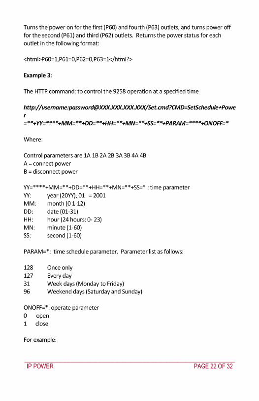
_____________________________________________________________________________
IP POWER PAGE 24 OF 32
The getpower command reports the status of power outlets 1-4 The setpower command controls the power outlets 1-4 with ldquo0rdquo turning power off and ldquo1rdquo turning power on Example 1 setpower =11110000 (This will turn on power 1-4) Example 2 setpower =11000000 (This turns on power on 1 amp 2 and turns off power 3 amp 4)
NOTE Only the first four numbers are used You can select from 0 to turn off the power to 1 to turn on the
power However with 155 the syntax requires to use eight separte digits If you only use four digits the command will not work properly
_____________________________________________________________________________
IP POWER PAGE 25 OF 32
Power outlet status and control using SNMP
Reading status
snmpget -v 1 -c public 192168155 1361419258210 (read status of Power1)
snmpget -v 1 -c public 192168155 1361419258220 (read status of Power2) snmpget -v 1 -c public 192168155 1361419258230 (read status of Power3) snmpget -v 1 -c public 192168155 1361419258240 (read status of Power4)
(Return value as ldquoINTEGER 1 rdquo means power ON Return value as ldquoINTEGER 0 rdquo means power OFF)
_____________________________________________________________________________
IP POWER PAGE 26 OF 32
Control outlet command
snmpset -v 1 -c public 192168155 1361419258210 integer 1 (turn on Power1) snmpset -v 1 -c public 192168155 1361419258220 integer 0 (turn off Power2)
snmpset -v 1 -c public 192168155 1361419258230 integer 1 (turn on Power3) snmpset -v 1 -c public 192168155 1361419258240 integer 0 (turn off Power4)
Power cycle outlet command snmpset -v 1 -c public 192168155 1361419258310 integer 1 (powercycle No1)
snmpset -v 1 -c public 192168155 1361419258320 integer 1 (powercycle No2) snmpset -v 1 -c public 192168155 1361419258330 integer 1 (powercycle No3)
_____________________________________________________________________________
IP POWER PAGE 27 OF 32
snmpset -v 1 -c public 192168155 1361419258340 integer 1 (powercycle No4)
If the power is on the outlet will turn ldquoOFF to ON ldquo when the power cycle command is placed However if powered off the outlet will turn ldquoON to OFF to ON ldquo when place power cycle command
9 Frequently Asked Question
Q1 I forgot the password and can not enter the administration page now what can I do A1 Use the username super user when logging in to the webpage and then click OK Turn the IP Power off for a few seconds the turn it back on The default username of admin and password of 12345678 will be restored Note there is a space between super and user
10 Manual Control Mode
The IP Power is generally controlled from a local or remote computer however the outlets can also be controlled manually
NOTE
Before using the manual control function it is necessary to UNPLUG DISCONNECT all of the 4 outlets
To obtain manual control
_____________________________________________________________________________
IP POWER PAGE 28 OF 32
Press and hold the ONOFF button (depicted below) for a full 5 seconds or until a sustained beep noise is heard ndash this enables manual control mode which can be identified by the flashing outlet lights
The outlet light that is not flashing is the one currently under manual control ndash this outlet can be turned on or off by pressing the ONOFF button
To select an alternate outlet to control press the Cycle button (labeled with a circle with arrows on it)
To disable manual control mode press and hold the ONOFF button for 5 seconds or until you can hear a sustained beep noise ndash signifying the deactivation of manual control mode
Cycle (left) Select power outlet to manually control
ONOFF (right) Press and hold to enabledisable manual control mode press to turn onoff the outlet selected by the cycle button
11 IP Power Control Using Console Server
The IP Power 9258 is a simple browser controlled power switch without the security features needed for open public network connection Nor does it have any remote out-of-band dial-in support
However the IP Power can be configured securely and its outlets can be controlled in-band and out of band when used in conjunction with an Opengear console server
Out of band access
The Opengear console server provides secure remoteout-of-band access through a dial in modem (or through an alternate broadband connection) To configure the console server for dial-in access
_____________________________________________________________________________
IP POWER PAGE 29 OF 32
Connect a modem to the consolemodem port and configure the console server for dial-in
The IP Power can then be network or serially connected to the console server
SSH tunneled control through the Console Server
If the IP Power is connected on the remote LAN with the console server then it can be browser controlled
Configure the console server with the IP Power as a HTTP accessible Host This Managed Device can then be remotely controlled securely using SSH tunneling (SDT)
Configure the remote SDTConnector client to access the gateway (console server) and then to connect to the IP Power using HTTP (refer wwwopengearcomfaq267html for details)
Console Server serial control
The IP Power is a principally a browser controlled unit and its RS232 serial port mainly provides diagnostic and status information (eg sending out its IP address and power on messages during Power On Self Test) However the IP Power serial port also supports emergency power control To configure the IP Power for serial control
Connect the IP Power 9258s CONSOLE RS232 port to one of the console server serial ports (for CM4001 2 this interconnection will use a standard UTP Cat 5 cable with a 319000 adapter at each end and all other console servers will only require one 319000 adaptor)
Configured the console server serial port with a serially controlled PDU
_____________________________________________________________________________
IP POWER PAGE 30 OF 32
The IP Power outlets are then controlled by securely (HTTPS) accessing the Manage Power menu on the console server Management Console (refer wwwopengearcomfaq231html for details)
NOTE
The outlet control commands are sent from the console server to the IP Power over the serial port
The combination of out of band access and IP Power serial port control can be particularly useful in managing remote sites where a DSL router (interconnect the office LAN and the internet) may have become dysfunctional requiring a power reset
12 General IP Power Control Using Serial Port
The IP Power RS232 serial port mainly provides diagnostic and status information however the serial port can be used for emergency power control as covered in the previous section
Usage power-ip9258 ltportgt ltoutletgt [outlet] on|off|status
The serial control script below is used in the console server and should work on a normal Linux box
binsh
out_udelay=50000
_____________________________________________________________________________
IP POWER PAGE 31 OF 32
out_retries=3
in_udelay=100000
in_retries=10
port=$1
outlets=$2 cmd=$3 tmpfile=tmptmp$$
if [[ -z $port ]] || [[ -z $outlets ]] || [[ -z $cmd ]] then appname=`basename $0`
echo Usage $appname ltportgt ltoutletgt [outlet] on|off|status exit 1 fi
function ipp_chat () out=$1
in=$2 cat $port gt $tmpfile amp
cat_pid=$ trap rm $tmpfile kill $cat_pid EXIT
for (( i=0 i lt $out_retries i++ )) do for (( j = 0 j lt $out j++ )) do usleep $out_udelay
echo -n $out$j1 gt $port done echo gt $port
for (( j=0 j lt $in_retries j++ )) do usleep $in_udelay line=`grep $in $tmpfile`
if [[ -n $line ]] then break 2 fi
done done
rm $tmpfile kill $cat_pid
if [[ -n $line ]] then echo $line else
echo Command failed ($out) exit 1 fi
Suppress error messages from the shell
exec 2gt devnull Set up the serial port for the IP Power
_____________________________________________________________________________
IP POWER PAGE 32 OF 32
stty 14004cbea3031c7f15401011131a012f17160000000000000
000 lt $port Enable serial command mode
ipp_chat 0ADEBUG9258Z IP9258 DEBUG ON ampgt devnull Get current status
status_nibble=`ipp_chat 0Ap06Z p6 | sed sp6()1g`
Send the command the least significant bit is port 1 the most significant is port 4 A value of 0 is on 1 is off
outlet_mask=0 for o in $outlets do outlet_bit=$(( 1ltlt $o-1 ))
outlet_mask=$(( outlet_mask | $outlet_bit )) done status_nibble=`printf d 0x$status_nibble`
if [[ $cmd == on ]] then echo Powering on outlet $outlets status_nibble=`printf X $(( $status_nibble amp ~$outlet_mask ))`
ipp_chat 0AP06F$status_nibbleZ P6=F$status_nibble ampgt devnull echo Outlet $outlets powered on
elif [[ $cmd == off ]] then echo Powering off outlet $outlets status_nibble=`printf X $(( $status_nibble | $outlet_mask ))`
ipp_chat 0AP06F$status_nibbleZ P6=F$status_nibble ampgt devnull echo Outlet $outlets powered off
else for o in $outlets do outlet_bit=$(( 1ltlt $o-1 ))
echo -n Outlet $o is if [[ $(( $status_nibble amp $outlet_bit )) -eq $outlet_bit ]] then echo off
else echo on fi
done fi
Disable serial command mode ipp_chat 0ADEBUG0FFZ IP9258 DEBUG OFF ampgt devnull exit 0
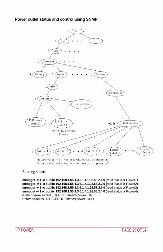
_____________________________________________________________________________
IP POWER PAGE 25 OF 32
Power outlet status and control using SNMP
Reading status
snmpget -v 1 -c public 192168155 1361419258210 (read status of Power1)
snmpget -v 1 -c public 192168155 1361419258220 (read status of Power2) snmpget -v 1 -c public 192168155 1361419258230 (read status of Power3) snmpget -v 1 -c public 192168155 1361419258240 (read status of Power4)
(Return value as ldquoINTEGER 1 rdquo means power ON Return value as ldquoINTEGER 0 rdquo means power OFF)
_____________________________________________________________________________
IP POWER PAGE 26 OF 32
Control outlet command
snmpset -v 1 -c public 192168155 1361419258210 integer 1 (turn on Power1) snmpset -v 1 -c public 192168155 1361419258220 integer 0 (turn off Power2)
snmpset -v 1 -c public 192168155 1361419258230 integer 1 (turn on Power3) snmpset -v 1 -c public 192168155 1361419258240 integer 0 (turn off Power4)
Power cycle outlet command snmpset -v 1 -c public 192168155 1361419258310 integer 1 (powercycle No1)
snmpset -v 1 -c public 192168155 1361419258320 integer 1 (powercycle No2) snmpset -v 1 -c public 192168155 1361419258330 integer 1 (powercycle No3)
_____________________________________________________________________________
IP POWER PAGE 27 OF 32
snmpset -v 1 -c public 192168155 1361419258340 integer 1 (powercycle No4)
If the power is on the outlet will turn ldquoOFF to ON ldquo when the power cycle command is placed However if powered off the outlet will turn ldquoON to OFF to ON ldquo when place power cycle command
9 Frequently Asked Question
Q1 I forgot the password and can not enter the administration page now what can I do A1 Use the username super user when logging in to the webpage and then click OK Turn the IP Power off for a few seconds the turn it back on The default username of admin and password of 12345678 will be restored Note there is a space between super and user
10 Manual Control Mode
The IP Power is generally controlled from a local or remote computer however the outlets can also be controlled manually
NOTE
Before using the manual control function it is necessary to UNPLUG DISCONNECT all of the 4 outlets
To obtain manual control
_____________________________________________________________________________
IP POWER PAGE 28 OF 32
Press and hold the ONOFF button (depicted below) for a full 5 seconds or until a sustained beep noise is heard ndash this enables manual control mode which can be identified by the flashing outlet lights
The outlet light that is not flashing is the one currently under manual control ndash this outlet can be turned on or off by pressing the ONOFF button
To select an alternate outlet to control press the Cycle button (labeled with a circle with arrows on it)
To disable manual control mode press and hold the ONOFF button for 5 seconds or until you can hear a sustained beep noise ndash signifying the deactivation of manual control mode
Cycle (left) Select power outlet to manually control
ONOFF (right) Press and hold to enabledisable manual control mode press to turn onoff the outlet selected by the cycle button
11 IP Power Control Using Console Server
The IP Power 9258 is a simple browser controlled power switch without the security features needed for open public network connection Nor does it have any remote out-of-band dial-in support
However the IP Power can be configured securely and its outlets can be controlled in-band and out of band when used in conjunction with an Opengear console server
Out of band access
The Opengear console server provides secure remoteout-of-band access through a dial in modem (or through an alternate broadband connection) To configure the console server for dial-in access
_____________________________________________________________________________
IP POWER PAGE 29 OF 32
Connect a modem to the consolemodem port and configure the console server for dial-in
The IP Power can then be network or serially connected to the console server
SSH tunneled control through the Console Server
If the IP Power is connected on the remote LAN with the console server then it can be browser controlled
Configure the console server with the IP Power as a HTTP accessible Host This Managed Device can then be remotely controlled securely using SSH tunneling (SDT)
Configure the remote SDTConnector client to access the gateway (console server) and then to connect to the IP Power using HTTP (refer wwwopengearcomfaq267html for details)
Console Server serial control
The IP Power is a principally a browser controlled unit and its RS232 serial port mainly provides diagnostic and status information (eg sending out its IP address and power on messages during Power On Self Test) However the IP Power serial port also supports emergency power control To configure the IP Power for serial control
Connect the IP Power 9258s CONSOLE RS232 port to one of the console server serial ports (for CM4001 2 this interconnection will use a standard UTP Cat 5 cable with a 319000 adapter at each end and all other console servers will only require one 319000 adaptor)
Configured the console server serial port with a serially controlled PDU
_____________________________________________________________________________
IP POWER PAGE 30 OF 32
The IP Power outlets are then controlled by securely (HTTPS) accessing the Manage Power menu on the console server Management Console (refer wwwopengearcomfaq231html for details)
NOTE
The outlet control commands are sent from the console server to the IP Power over the serial port
The combination of out of band access and IP Power serial port control can be particularly useful in managing remote sites where a DSL router (interconnect the office LAN and the internet) may have become dysfunctional requiring a power reset
12 General IP Power Control Using Serial Port
The IP Power RS232 serial port mainly provides diagnostic and status information however the serial port can be used for emergency power control as covered in the previous section
Usage power-ip9258 ltportgt ltoutletgt [outlet] on|off|status
The serial control script below is used in the console server and should work on a normal Linux box
binsh
out_udelay=50000
_____________________________________________________________________________
IP POWER PAGE 31 OF 32
out_retries=3
in_udelay=100000
in_retries=10
port=$1
outlets=$2 cmd=$3 tmpfile=tmptmp$$
if [[ -z $port ]] || [[ -z $outlets ]] || [[ -z $cmd ]] then appname=`basename $0`
echo Usage $appname ltportgt ltoutletgt [outlet] on|off|status exit 1 fi
function ipp_chat () out=$1
in=$2 cat $port gt $tmpfile amp
cat_pid=$ trap rm $tmpfile kill $cat_pid EXIT
for (( i=0 i lt $out_retries i++ )) do for (( j = 0 j lt $out j++ )) do usleep $out_udelay
echo -n $out$j1 gt $port done echo gt $port
for (( j=0 j lt $in_retries j++ )) do usleep $in_udelay line=`grep $in $tmpfile`
if [[ -n $line ]] then break 2 fi
done done
rm $tmpfile kill $cat_pid
if [[ -n $line ]] then echo $line else
echo Command failed ($out) exit 1 fi
Suppress error messages from the shell
exec 2gt devnull Set up the serial port for the IP Power
_____________________________________________________________________________
IP POWER PAGE 32 OF 32
stty 14004cbea3031c7f15401011131a012f17160000000000000
000 lt $port Enable serial command mode
ipp_chat 0ADEBUG9258Z IP9258 DEBUG ON ampgt devnull Get current status
status_nibble=`ipp_chat 0Ap06Z p6 | sed sp6()1g`
Send the command the least significant bit is port 1 the most significant is port 4 A value of 0 is on 1 is off
outlet_mask=0 for o in $outlets do outlet_bit=$(( 1ltlt $o-1 ))
outlet_mask=$(( outlet_mask | $outlet_bit )) done status_nibble=`printf d 0x$status_nibble`
if [[ $cmd == on ]] then echo Powering on outlet $outlets status_nibble=`printf X $(( $status_nibble amp ~$outlet_mask ))`
ipp_chat 0AP06F$status_nibbleZ P6=F$status_nibble ampgt devnull echo Outlet $outlets powered on
elif [[ $cmd == off ]] then echo Powering off outlet $outlets status_nibble=`printf X $(( $status_nibble | $outlet_mask ))`
ipp_chat 0AP06F$status_nibbleZ P6=F$status_nibble ampgt devnull echo Outlet $outlets powered off
else for o in $outlets do outlet_bit=$(( 1ltlt $o-1 ))
echo -n Outlet $o is if [[ $(( $status_nibble amp $outlet_bit )) -eq $outlet_bit ]] then echo off
else echo on fi
done fi
Disable serial command mode ipp_chat 0ADEBUG0FFZ IP9258 DEBUG OFF ampgt devnull exit 0
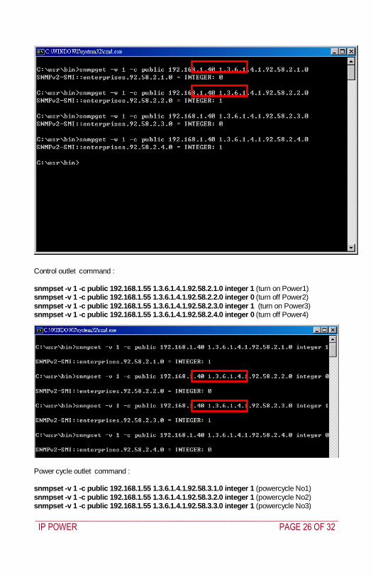
_____________________________________________________________________________
IP POWER PAGE 26 OF 32
Control outlet command
snmpset -v 1 -c public 192168155 1361419258210 integer 1 (turn on Power1) snmpset -v 1 -c public 192168155 1361419258220 integer 0 (turn off Power2)
snmpset -v 1 -c public 192168155 1361419258230 integer 1 (turn on Power3) snmpset -v 1 -c public 192168155 1361419258240 integer 0 (turn off Power4)
Power cycle outlet command snmpset -v 1 -c public 192168155 1361419258310 integer 1 (powercycle No1)
snmpset -v 1 -c public 192168155 1361419258320 integer 1 (powercycle No2) snmpset -v 1 -c public 192168155 1361419258330 integer 1 (powercycle No3)
_____________________________________________________________________________
IP POWER PAGE 27 OF 32
snmpset -v 1 -c public 192168155 1361419258340 integer 1 (powercycle No4)
If the power is on the outlet will turn ldquoOFF to ON ldquo when the power cycle command is placed However if powered off the outlet will turn ldquoON to OFF to ON ldquo when place power cycle command
9 Frequently Asked Question
Q1 I forgot the password and can not enter the administration page now what can I do A1 Use the username super user when logging in to the webpage and then click OK Turn the IP Power off for a few seconds the turn it back on The default username of admin and password of 12345678 will be restored Note there is a space between super and user
10 Manual Control Mode
The IP Power is generally controlled from a local or remote computer however the outlets can also be controlled manually
NOTE
Before using the manual control function it is necessary to UNPLUG DISCONNECT all of the 4 outlets
To obtain manual control
_____________________________________________________________________________
IP POWER PAGE 28 OF 32
Press and hold the ONOFF button (depicted below) for a full 5 seconds or until a sustained beep noise is heard ndash this enables manual control mode which can be identified by the flashing outlet lights
The outlet light that is not flashing is the one currently under manual control ndash this outlet can be turned on or off by pressing the ONOFF button
To select an alternate outlet to control press the Cycle button (labeled with a circle with arrows on it)
To disable manual control mode press and hold the ONOFF button for 5 seconds or until you can hear a sustained beep noise ndash signifying the deactivation of manual control mode
Cycle (left) Select power outlet to manually control
ONOFF (right) Press and hold to enabledisable manual control mode press to turn onoff the outlet selected by the cycle button
11 IP Power Control Using Console Server
The IP Power 9258 is a simple browser controlled power switch without the security features needed for open public network connection Nor does it have any remote out-of-band dial-in support
However the IP Power can be configured securely and its outlets can be controlled in-band and out of band when used in conjunction with an Opengear console server
Out of band access
The Opengear console server provides secure remoteout-of-band access through a dial in modem (or through an alternate broadband connection) To configure the console server for dial-in access
_____________________________________________________________________________
IP POWER PAGE 29 OF 32
Connect a modem to the consolemodem port and configure the console server for dial-in
The IP Power can then be network or serially connected to the console server
SSH tunneled control through the Console Server
If the IP Power is connected on the remote LAN with the console server then it can be browser controlled
Configure the console server with the IP Power as a HTTP accessible Host This Managed Device can then be remotely controlled securely using SSH tunneling (SDT)
Configure the remote SDTConnector client to access the gateway (console server) and then to connect to the IP Power using HTTP (refer wwwopengearcomfaq267html for details)
Console Server serial control
The IP Power is a principally a browser controlled unit and its RS232 serial port mainly provides diagnostic and status information (eg sending out its IP address and power on messages during Power On Self Test) However the IP Power serial port also supports emergency power control To configure the IP Power for serial control
Connect the IP Power 9258s CONSOLE RS232 port to one of the console server serial ports (for CM4001 2 this interconnection will use a standard UTP Cat 5 cable with a 319000 adapter at each end and all other console servers will only require one 319000 adaptor)
Configured the console server serial port with a serially controlled PDU
_____________________________________________________________________________
IP POWER PAGE 30 OF 32
The IP Power outlets are then controlled by securely (HTTPS) accessing the Manage Power menu on the console server Management Console (refer wwwopengearcomfaq231html for details)
NOTE
The outlet control commands are sent from the console server to the IP Power over the serial port
The combination of out of band access and IP Power serial port control can be particularly useful in managing remote sites where a DSL router (interconnect the office LAN and the internet) may have become dysfunctional requiring a power reset
12 General IP Power Control Using Serial Port
The IP Power RS232 serial port mainly provides diagnostic and status information however the serial port can be used for emergency power control as covered in the previous section
Usage power-ip9258 ltportgt ltoutletgt [outlet] on|off|status
The serial control script below is used in the console server and should work on a normal Linux box
binsh
out_udelay=50000
_____________________________________________________________________________
IP POWER PAGE 31 OF 32
out_retries=3
in_udelay=100000
in_retries=10
port=$1
outlets=$2 cmd=$3 tmpfile=tmptmp$$
if [[ -z $port ]] || [[ -z $outlets ]] || [[ -z $cmd ]] then appname=`basename $0`
echo Usage $appname ltportgt ltoutletgt [outlet] on|off|status exit 1 fi
function ipp_chat () out=$1
in=$2 cat $port gt $tmpfile amp
cat_pid=$ trap rm $tmpfile kill $cat_pid EXIT
for (( i=0 i lt $out_retries i++ )) do for (( j = 0 j lt $out j++ )) do usleep $out_udelay
echo -n $out$j1 gt $port done echo gt $port
for (( j=0 j lt $in_retries j++ )) do usleep $in_udelay line=`grep $in $tmpfile`
if [[ -n $line ]] then break 2 fi
done done
rm $tmpfile kill $cat_pid
if [[ -n $line ]] then echo $line else
echo Command failed ($out) exit 1 fi
Suppress error messages from the shell
exec 2gt devnull Set up the serial port for the IP Power
_____________________________________________________________________________
IP POWER PAGE 32 OF 32
stty 14004cbea3031c7f15401011131a012f17160000000000000
000 lt $port Enable serial command mode
ipp_chat 0ADEBUG9258Z IP9258 DEBUG ON ampgt devnull Get current status
status_nibble=`ipp_chat 0Ap06Z p6 | sed sp6()1g`
Send the command the least significant bit is port 1 the most significant is port 4 A value of 0 is on 1 is off
outlet_mask=0 for o in $outlets do outlet_bit=$(( 1ltlt $o-1 ))
outlet_mask=$(( outlet_mask | $outlet_bit )) done status_nibble=`printf d 0x$status_nibble`
if [[ $cmd == on ]] then echo Powering on outlet $outlets status_nibble=`printf X $(( $status_nibble amp ~$outlet_mask ))`
ipp_chat 0AP06F$status_nibbleZ P6=F$status_nibble ampgt devnull echo Outlet $outlets powered on
elif [[ $cmd == off ]] then echo Powering off outlet $outlets status_nibble=`printf X $(( $status_nibble | $outlet_mask ))`
ipp_chat 0AP06F$status_nibbleZ P6=F$status_nibble ampgt devnull echo Outlet $outlets powered off
else for o in $outlets do outlet_bit=$(( 1ltlt $o-1 ))
echo -n Outlet $o is if [[ $(( $status_nibble amp $outlet_bit )) -eq $outlet_bit ]] then echo off
else echo on fi
done fi
Disable serial command mode ipp_chat 0ADEBUG0FFZ IP9258 DEBUG OFF ampgt devnull exit 0
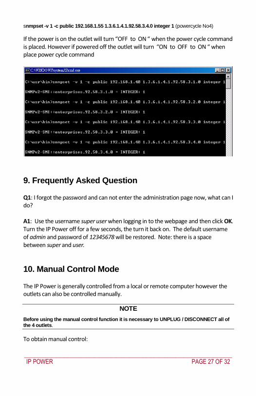
_____________________________________________________________________________
IP POWER PAGE 29 OF 32
Connect a modem to the consolemodem port and configure the console server for dial-in
The IP Power can then be network or serially connected to the console server
SSH tunneled control through the Console Server
If the IP Power is connected on the remote LAN with the console server then it can be browser controlled
Configure the console server with the IP Power as a HTTP accessible Host This Managed Device can then be remotely controlled securely using SSH tunneling (SDT)
Configure the remote SDTConnector client to access the gateway (console server) and then to connect to the IP Power using HTTP (refer wwwopengearcomfaq267html for details)
Console Server serial control
The IP Power is a principally a browser controlled unit and its RS232 serial port mainly provides diagnostic and status information (eg sending out its IP address and power on messages during Power On Self Test) However the IP Power serial port also supports emergency power control To configure the IP Power for serial control
Connect the IP Power 9258s CONSOLE RS232 port to one of the console server serial ports (for CM4001 2 this interconnection will use a standard UTP Cat 5 cable with a 319000 adapter at each end and all other console servers will only require one 319000 adaptor)
Configured the console server serial port with a serially controlled PDU
_____________________________________________________________________________
IP POWER PAGE 30 OF 32
The IP Power outlets are then controlled by securely (HTTPS) accessing the Manage Power menu on the console server Management Console (refer wwwopengearcomfaq231html for details)
NOTE
The outlet control commands are sent from the console server to the IP Power over the serial port
The combination of out of band access and IP Power serial port control can be particularly useful in managing remote sites where a DSL router (interconnect the office LAN and the internet) may have become dysfunctional requiring a power reset
12 General IP Power Control Using Serial Port
The IP Power RS232 serial port mainly provides diagnostic and status information however the serial port can be used for emergency power control as covered in the previous section
Usage power-ip9258 ltportgt ltoutletgt [outlet] on|off|status
The serial control script below is used in the console server and should work on a normal Linux box
binsh
out_udelay=50000
_____________________________________________________________________________
IP POWER PAGE 31 OF 32
out_retries=3
in_udelay=100000
in_retries=10
port=$1
outlets=$2 cmd=$3 tmpfile=tmptmp$$
if [[ -z $port ]] || [[ -z $outlets ]] || [[ -z $cmd ]] then appname=`basename $0`
echo Usage $appname ltportgt ltoutletgt [outlet] on|off|status exit 1 fi
function ipp_chat () out=$1
in=$2 cat $port gt $tmpfile amp
cat_pid=$ trap rm $tmpfile kill $cat_pid EXIT
for (( i=0 i lt $out_retries i++ )) do for (( j = 0 j lt $out j++ )) do usleep $out_udelay
echo -n $out$j1 gt $port done echo gt $port
for (( j=0 j lt $in_retries j++ )) do usleep $in_udelay line=`grep $in $tmpfile`
if [[ -n $line ]] then break 2 fi
done done
rm $tmpfile kill $cat_pid
if [[ -n $line ]] then echo $line else
echo Command failed ($out) exit 1 fi
Suppress error messages from the shell
exec 2gt devnull Set up the serial port for the IP Power
_____________________________________________________________________________
IP POWER PAGE 32 OF 32
stty 14004cbea3031c7f15401011131a012f17160000000000000
000 lt $port Enable serial command mode
ipp_chat 0ADEBUG9258Z IP9258 DEBUG ON ampgt devnull Get current status
status_nibble=`ipp_chat 0Ap06Z p6 | sed sp6()1g`
Send the command the least significant bit is port 1 the most significant is port 4 A value of 0 is on 1 is off
outlet_mask=0 for o in $outlets do outlet_bit=$(( 1ltlt $o-1 ))
outlet_mask=$(( outlet_mask | $outlet_bit )) done status_nibble=`printf d 0x$status_nibble`
if [[ $cmd == on ]] then echo Powering on outlet $outlets status_nibble=`printf X $(( $status_nibble amp ~$outlet_mask ))`
ipp_chat 0AP06F$status_nibbleZ P6=F$status_nibble ampgt devnull echo Outlet $outlets powered on
elif [[ $cmd == off ]] then echo Powering off outlet $outlets status_nibble=`printf X $(( $status_nibble | $outlet_mask ))`
ipp_chat 0AP06F$status_nibbleZ P6=F$status_nibble ampgt devnull echo Outlet $outlets powered off
else for o in $outlets do outlet_bit=$(( 1ltlt $o-1 ))
echo -n Outlet $o is if [[ $(( $status_nibble amp $outlet_bit )) -eq $outlet_bit ]] then echo off
else echo on fi
done fi
Disable serial command mode ipp_chat 0ADEBUG0FFZ IP9258 DEBUG OFF ampgt devnull exit 0
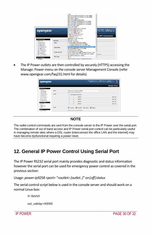
_____________________________________________________________________________
IP POWER PAGE 32 OF 32
stty 14004cbea3031c7f15401011131a012f17160000000000000
000 lt $port Enable serial command mode
ipp_chat 0ADEBUG9258Z IP9258 DEBUG ON ampgt devnull Get current status
status_nibble=`ipp_chat 0Ap06Z p6 | sed sp6()1g`
Send the command the least significant bit is port 1 the most significant is port 4 A value of 0 is on 1 is off
outlet_mask=0 for o in $outlets do outlet_bit=$(( 1ltlt $o-1 ))
outlet_mask=$(( outlet_mask | $outlet_bit )) done status_nibble=`printf d 0x$status_nibble`
if [[ $cmd == on ]] then echo Powering on outlet $outlets status_nibble=`printf X $(( $status_nibble amp ~$outlet_mask ))`
ipp_chat 0AP06F$status_nibbleZ P6=F$status_nibble ampgt devnull echo Outlet $outlets powered on
elif [[ $cmd == off ]] then echo Powering off outlet $outlets status_nibble=`printf X $(( $status_nibble | $outlet_mask ))`
ipp_chat 0AP06F$status_nibbleZ P6=F$status_nibble ampgt devnull echo Outlet $outlets powered off
else for o in $outlets do outlet_bit=$(( 1ltlt $o-1 ))
echo -n Outlet $o is if [[ $(( $status_nibble amp $outlet_bit )) -eq $outlet_bit ]] then echo off
else echo on fi
done fi
Disable serial command mode ipp_chat 0ADEBUG0FFZ IP9258 DEBUG OFF ampgt devnull exit 0