ip telephony - welcome to communications · pdf filechristine hayes ben stamm ... technology...
TRANSCRIPT

IP TELEPHONY
A Report to the IHETS Integrated Technology Committee Prepared By IP Telephony Task Force Indiana Higher Education Telecommunication System June 3, 2003

Contents
Participant List ............................................................................................................................... iii Executive Summary ....................................................................................................................... vi Introduction......................................................................................................................................1 IP Telephony Considerations...........................................................................................................3 IP Telephony Vendor Approaches...................................................................................................8 Avaya ...................................................................................................................................8 Cisco ....................................................................................................................................9 Mitel...................................................................................................................................13 Nortel Networks.................................................................................................................14 Infrastructure Requirements...........................................................................................................17 E-911..............................................................................................................................................18 Session Initiated Protocol (SIP) .....................................................................................................22 Quality of Service (QoS) ...............................................................................................................30 Equipment Testing.........................................................................................................................40 Pilot Projects ..................................................................................................................................42 Business Case.................................................................................................................................45 Appendix A: ITU Audio Standards ...............................................................................................48 Appendix B: Nortel Networks/IHETS/FSSA Test Plan ................................................................49 Appendix C: Vendor IP Telephony Websites................................................................................61 Appendix D: Avaya Site Survey....................................................................................................63 Appendix E: Cisco Site Survey......................................................................................................73 Appendix F: Mitel Site Survey ......................................................................................................90 Appendix G: Nortel Networks Site Survey .................................................................................101 Glossary .......................................................................................................................................108
ii

Participant List IP Telephony Task Force Members
Indiana Higher Education Telecommunication System
Anderson University Joe Royer
Max Gordon David Kaufman AT&T WorldNet George Khazal Steve Dearing Tony McClelland Bob Noe Ball State University Kevin Siminski Amy Berg Shawn Solomon Fred Nay Alan Stillerman Ed Stockey, Chairperson DePauw University Ed Tully C Gierke Barry Wray Franklin College Indiana Technology Oversight Commission
Dagrun Bennett
Jean Corder Goshen College Gilbert Glenn Indiana State University Tim Cottom Huntington College Gerry Oliver Kerry Arnold Julie Hendryx Indiana University Marianne Chitwood Indiana 211 Paul Clegg Lucinda Nord Steve Egyhazi Mike Enyeart Indiana Department of Education Doug Pearson Mike Huffman Indiana University Purdue University Indianapolis
Indiana Department of Family and Social Services Administration
David Jent Jack Hogan Shawn Henderson Indiana Wesleyan University Art Mahan Indiana Department of Information
Technology Daniel Metz Corwin Foote Indianapolis Marion County Public Library
Steve Reed Phil Thoben
Brian Stone
iii

University of Evansville Intelenet Commission Keith Jackson Dick Holmes Chad Miller University of Notre Dame Jerry Sullivan Steven Ellis
Ivy Tech State College Gordon Wishon Jason Whitaker University of Saint Francis
Kentucky Community and Technical College System
Theresa Sordelet University of Southern Indiana Phil Duvall Wayne Bohm
Manchester College Tim Lockridge Larry Gyrion Valparaiso University
Purdue University Calumet Dwight Batey Shelly Lapeer Vincennes University
Purdue University North Central Carl Koenig Ben Stamm Christine Hayes Wabash College Purdue University West Lafayette Bill Doemel Gary English Bradley Weaver Michael Gay Pat Smoker Ed Stanisz, Rose Hulman James Koutsoumpas
Taylor University Stephen Olsen
Saint Joseph College Tony Baltes
Saint Mary’s College Joel Cooper Saint Mary of the Woods College
Michael Patrick University of Indianapolis
Beth Kiggins
iv

Document Preparation Business Case Committee Members
Ball State University Indiana Higher Education Telecommunication System Amy Berg
Max Gordon Indiana Department of Family and Social Services Administration
Bob Noe Shawn Solomon
Shawn Henderson Alan Stillerman Ed Stockey Indiana University Barry Wray Marianne Chitwood Indiana Department of Information Technology Steve Reed Phil Thoben Indiana Higher Education Telecommunication System Bob Noe Ed Stockey Other Contributors North American Communications Resource (Avaya) Brenda Papszycki, Jennifer Ping Cisco Systems, Inc. Bruce Kennedy Information Management Group (Mitel) Tim Wills Joseph Wilson Nortel Networks Lonny Hatland Greg Palatinus Dave Finn
v

Executive Summary In May 2002, the IHETS IP Telephony Task Force gathered for a first meeting to evaluate the technology and business case for IP Telephony. The Task Force report will provide guidance for institutions looking to evaluate IP Telephony as a possible solution. This guidance should provide the institution a technical overview of several possible vendor solutions. The business case will vary by institution and is dependant upon several factors, including legacy equipment, end of life, number of locations, and current infrastructure. The choice of vendor will depend upon the size of the remote installation, number of locations, the need for isolated survivability, and the existing infrastructure. Topics included in this document:
• IP Telephony Considerations • IP Telephony Vendor Approaches • Infrastructure Requirements • Enhanced-911 (E-911) • Session Initiated Protocol (SIP) • Quality of Service (QoS) • Equipment Testing • Pilot Projects • Business Case • Appendixes • Glossary
It was found that no IP Gateway interoperability was demonstrated by any of the vendors tested. Because of this, any interconnectivity between vendors would require implementation of traditional telephony trunking. In an enterprise type scenario where an organization has multiple vendor implementations, cost will be higher in order to provision for intercommunications between systems. This report will not select a vendor or brand for those who are contemplating an IP Telephony system. It will provide a set of issues to consider and a methodology for their consideration.
vi

Introduction
IP Telephony is situated as the driving force for the next generation of enterprise telephony systems. The advantages of an IP-based infrastructure are too important to ignore as many traditional telephony systems are reaching the twilight of their lifecycles. Some of the drivers pushing the move toward IP Telephony are:
• The Vendors • Technology • Aging equipment • Productivity gains • Consolidation of networks • Simplifying Moves/Adds/Changes
Some advantages of VoIP are:
• A convergence to a single network from separate voice and data networks • More Seamless operating staff between voice and data operations • Lower operating costs • Fewer LEC lines may be needed within an enterprise with multiple sites • Reduction in long distance toll charges between campuses or sites within the enterprise
A synopsis of each section follows:
IP Telephony Considerations - What questions should be asked when contemplating moving from an existing telephony infrastructure to an IP Telephony infrastructure. IP Telephony Vendor Approaches – Four vendors were approached for testing their IP Telephony solution. Profiles of Avaya, Cisco, Mitel, and Nortel Networks are presented based on what was tested. Infrastructure Requirements – A listing of common questions that each vendor asks as well as some of the differences between the forms. Actual site surveys for each vendor are located in the appendix. E-911 – Stands for Enhanced 911. A review of what E-911 is and how E-911 works. Session Initiated Protocol (SIP) - An introduction to the basics of SIP and its relation to IP Telephony. Quality of Service (QoS) - Learn why QoS is needed and a method used to make it work. Equipment Testing – Profiles the testing done with Avaya and Mitel.
1

Pilot Projects - Provides information on how Cisco and Nortel Networks products worked and how they can be implemented. The Business Case - Considerations, thoughts, and ideas to think about before implementing an IP Telephony system. Appendix A – Brief description of ITU Audio Standards. Appendix B – Test Plan from Nortel Networks on the IHETS/FSSA Pilot Project. Appendix C – Listing of vendor web sites for their IP Telephony products. Appendix D – Avaya’s Site Survey Appendix E – Cisco’s Site Survey Appendix F – Mitel’s Site Survey Appendix G – Nortel Networks Site Survey Glossary – Listing of terms used in this document.
Sections such as IP Telephony Considerations, E-911, SIP and QoS start out with a question and answer format and identify key terms relevant to the section. All definitions of key terms are also located in the glossary. Primary objectives of this report include the identification of factors to be evaluated, means to evaluate these factors, and information on the technology itself. Some of the differing approaches that vendors use in their product offering(s) are presented. Most if not all vendors provide a “Return on Investment” calculator or similar tool for those considering their products. This report will not identify any vendor as preferred, but will provide information needed to make an informed decision on IP Telephony.
2

IP Telephony Considerations VoIP by definition is the technology of transmitting voice conversations over a data network using IP (Internet Protocol). IP Telephony is the ability to make a phone call using an IP based device. The convergence of voice, video, and data enhances our ability to collaborate with tools such as video conferencing, instant messaging and unified messaging. In the following paragraphs, IP Telephony is discussed and different options are explained. Not all solutions are the same and some vendors vary greatly from each other. In this section, differences in design, in addition to descriptions of some services and optional features, are reviewed. Primary Questions
• What is H.323? • What is SIP? • What is an IP enabled PBX? • What is an IP PBX/Soft-switch? • Will vendors support inter-operability with IP phones? • Will my network support IP Telephony? • What are the security implications with IP Telephony? • Can I integrate voicemail and email functions?
Answers What is H.323? H.323 is the International Telecommunications Union – Telecommunication Standardization Sector (ITU-T) standard for packet based multimedia communications systems. H.323 is currently the default standard for IP telephony, with Session Initiated Protocol quickly becoming just as important as H.323. H.323 allows for the voice packets to traverse an IP network. What is SIP? SIP stands for Session Initiated Protocol. SIP is covered in the Request For Comments (RFC) 2543. SIP is a text-based, layer seven, protocol designed to work with the establishment, modification, and termination of conferencing and telephony multimedia packets over an IP-based network. SIP is an easier protocol than H.323 to implement and use. See the Session Initiated Protocol section for more details on SIP. What is an IP Enabled PBX (Private Branch eXchange)? The IP enabled PBX system typically incorporates an “all-in-one” solution that contains the necessary resources for operation. The implied resources are line-cards for PSTN (Public Switched Telephone Network) connectivity, station-cards for telephones, voicemail, Interactive Voice Response, and a management application. This solution is more typical of a traditional PBX deployment. This implementation can give administrators a little more flexibility in placement of IP, digital, or analog phones. Take this in consideration when choosing a solution for your organization. If your campus is not wired with the proper cabling or network infrastructure, a PBX that blends
3

the three types of end-points can be of great benefit to your organization. This may ultimately be a more cost effective manner while still being able to take advantage of IP telephony in qualified areas. The big upside to this deployment is that in many cases a “traditional” PBX can be “IP enabled” to take advantage of some of the features that IP Telephony offers. This in turn would help prevent a complete upgrade (i.e., removing all existing hardware and software and replacing with new hardware and software), which can save money, not to mention resources, in a new deployment. What is an IP PBX/Soft-switch? This new “breed” of PBX presents a whole new spectrum in communications. By design, the IP PBX incorporates many of the same features that are found in traditional PBXs, the difference being in the architecture and methods in which the applications communicate. By comparison, traditional PBXs are typically proprietary designs that are implemented in a stand-alone fashion while the newer IP PBXs tend to look more like an application server on the network. A very noticeable difference for some IP PBXs is that they do not need station cards, while other solutions use station or Session Initiated Protocol (SIP) cards to manage Real Time Transport Protocol (RTP) streams. Voicemail servers no longer have to communicate via T-1 or ISDN and applications can now be developed and pushed out to the IP phones. This communication takes advantage of network protocols such as H.323, SIP, or in some cases proprietary protocols to make this happen. This can help reduce the amount of hardware needed in the network because you are taking advantage of the existing infrastructure. There is a big advantage with the IP PBX deployment model if an organization’s infrastructure will support it. Will vendors support inter-operability with IP phones? Choosing a particular IP phone will depend on what services and solutions you would like to implement. As many vendors design and implement new features and services for IP Telephony, a key factor in your decision making may be the phones themselves. Appearance and features such as inline power and protocol stacks that are built into the phones are factors that need to be investigated. With deployments such as Pingtel or Interactive Intelligence, the option to use Cisco’s IP phone exists due to the use of SIP. Another benefit is the browser functionality built into the phones. Custom applications can be created for the IP phones that support XML, JAVA, or a comparable development language. To further expand on IP phone functionality, here are a few options to consider:
• Session Initiated Protocol (SIP) – Does the vendor support SIP and is the phone already SIP enabled? In other words, is the IP phone capable of communicating via the SIP protocol? IP phones from Cisco and Pingtel both have the SIP stack built-in. An example of SIP today is having the ability to view the status of a user’s phone through their instant messaging client. SIP deployments like Pingtel and Interactive Intelligence also take advantage of SIP addressing. What this means is that a user can be called from an SIP client using an address like [email protected], instead of the standard E.164 phone number.
• Purchasing SIP “enabled” phones for an IP telephony deployment now may help financially in the future, as SIP becomes more of a standard for IP telephony. This may also provide more leverage and less dependency upon a vendor. This option has been widely unavailable in the past with telecommunications.
4

• Inline Power – What method do you propose in providing power to the phones? Cisco and Nortel Networks both drive power over Ethernet, while other phones use power cords attached to the IP phones. The upside to inline power is having backup power available to the IP phones in the event that power to a facility is lost. This is presuming that network devices have backup power. Both Cisco and Nortel Networks have power over Ethernet available today in their network switches. It should be noted that at the writing of this document the Power over Ethernet standard 802.3af has not been ratified.
• Web application(s) – XML/JAVA – Will the IP phones support a Web browser? What types of applications can be pushed to the phones? Can the phones be used for data input/retrieval, to act as an information appliance? Both Cisco and Pingtel have built-in Web browsers for the display on the IP phones. This can provide an avenue to push services like Web browsing, stock tickers, yellow pages, UPS/FedEX package tracking, real-time classroom attendance and a host of other applications to the phones. Many packaged XML solutions are available, targeted to higher education and other vertical markets, and custom XML/Java development is generally an inexpensive proposition.
• Vendor Inter-operability – Finally, but most importantly, does the implementation that one chooses support IP phones from multiple vendors? While this may initially sound odd, this is becoming more and more the reality brought forth with IP Telephony. In the past with digital phones, PBXs were basically proprietary. With the advent of IP telephony and SIP, interoperability between vendors becomes more viable for deployment models.
Will my network support IP Telephony? This will vary depending upon the existing network infrastructure. If there is currently a Private Branch Exchange (PBX), it may be possible to have additional cards installed to make it IP capable. Other items to consider are:
• Quality of Service (QoS) – Is the bandwidth utilization on the local or wide area network accounted for? Is there any form of QoS in the network? QoS can be addressed by prioritizing voice traffic and by implementing VLAN technology. For more information on QoS, please refer to the QoS section in this document.
• VLANs – The use of Virtual Local Area Networks (VLANs) in an IP Telephony deployment is recommended. VLANs provide key functionality in two ways. First, by segmenting IP phones into their own VLAN, DOS (Denial Of Service) attacks can be eliminated. Second, VLANs are a great help in implementing QoS. By segmenting the IP phones into their own VLAN, excess traffic on a segment can be eliminated.
• Inline Power – Is this a needed or desired feature? How will backup power to the phones be provided, in the event of power failure? The IEEE standard 802.3af addresses the ability to deploy power over Ethernet for devices such as IP phones and wireless access points.
What are the security implications of IP Telephony? Operating a single network for voice and video brings further attention to the security needs of voice systems. Many of the issues remain from legacy TDM systems, such as toll fraud, with some additional issues such as web-based interfaces and denial-of-service attacks. Vendors have combined system features and network design recommendations to mitigate each risk, enabling the successful deployment of IP
5

Telephony into the most critical environments (hospitals, public safety or first-responder units, financial service organizations, etc.). Although not a complete discussion of network or voice security, some issues are worth considering.
• Dedicated VLANs for IP phones, IP PBXs and IP Telephony applications. Although these devices will be spread throughout the organization, using one or more VLANs for voice endpoints allows simpler enforcement of different security policies for voice endpoints than desktops. The traffic characteristics and needs for an IP phone are much narrower and easier to enforce than a desktop, significantly reducing the opportunity for denial-of-service attacks.
• Strong endpoint and user authentication. The 802.1x standard offers a mechanism for organizations to authenticate users to the network before allowing any traffic onto the network, and can be used to put the user into a specific VLAN and push per-user access policies (generally access lists) to the user’s switch port. This capability mitigates the current reliance organization’s have on physical security, by which any port inside an organization’s physical walls typically offers wide-open access to the IP network. By requiring user authentication, physical breaches and common areas no longer represent a security vulnerability. Guest access can be offered by placing failed authentications into a general purpose VLAN with Internet-only access. IP Phones do not currently support 802.1x, but a new generation of phones are expected to deliver this capability.
• Security on IP PBX infrastructure. Vendor approaches to securing IP PBXs and IP Telephony applications vary, but the end goal is the same. Restricting visibility of IP PBX infrastructure (with dedicated VLANs) reduces the threat; intrusion prevention software resident on IP PBXs further protects the traffic from the “allowed” pool of users. These mechanisms should be considered for any general-purpose operating system (Windows, Linux, etc.).
• Strong security policy and enforcement mechanisms. The strength of a network’s security hinges on a solid policy. Security policy must relate existing systems and connectivity requirements with the appropriate threats and vulnerabilities, enabling the gap to be identified and managed on an ongoing basis. While security enforcement has traditionally been reactive, recent offerings have shifted the focus to proactive or real-time prevention.
Can I integrate voicemail and email functions? The answer to this is yes and there are a couple of different methods to take into account. Unified Messaging (UM) is the combining of voicemail, electronic mail, and facsimile into a central repository for storage and accessibility. The advantage of UM is that it gives users the ability to read, listen, and reply to various collaborations from a client such as Outlook or Eudora. A number of vendors provide unified messaging services through the use of SMTP (Simple Mail Transport Protocol). With this method, a message is stored on a voicemail server, then encoded in a “wave” file format and sent to a recipient. This form of UM does not rely on using a mail server as the repository for messages. They are basically “popped” to a client, such as Outlook or Eudora. The downside to not integrating with a mail server is that the message is not in one central location in electronic format, although they may be stored on the actual voicemail system.
6

Another form of Unified messaging would “hook” into a campus or corporate mail server(s), which would then provide a central location for voicemail, facsimile, and email. The difference between the two models is that one essentially integrates with the email platform and the other model does not. The upside to this methodology is that all messages are kept in a central repository. This in turn makes it easier for users to access and manage his or her messages from a client on a workstation or Web browser at a remote location.
7

IP Telephony Vendor Approaches Ask five different people how they would solve a problem and you will get five different answers. This is no different with vendors as they apply their view to the latest protocol that they want to promote. In this section, four vendors and their approaches to IP Telephony are profiled. They are in alphabetical order: Avaya, Cisco, Mitel, and Nortel Networks. Avaya 1. Introduction 2. G700 Media Gateway 3. S8300 Media Server Module 4. IP Phones 1. Introduction North American Communications Resource (NACR) installed the Avaya IP telephony product for testing in early November 2002. The package consisted of a G700 Media Gateway with a S8300 Media Server Module. 2. G700 Media Gateway The G700 Media Gateway contains VoIP resources, a layer 2 switch, modular interface connectivity for traditional trunk and station access and performs the function of a gateway/gatekeeper. Each G700 Media Gateway VoIP Media Module can support up to 64 G.711 single channel calls or 32 compression codec (G.729 or G.723) TDM/IP simultaneous calls. If the desire is to have an essentially non-blocking system, then an additional VoIP Media Module needs to be added if more than two T1/E1 Media Modules are used in a single chassis. The G700 Media Gateway offers five types of Media Modules; T1/E1, ISDN BRI, Loop Start/Ground Start Trunks, as well as connections to TDM based endpoints such as DCP digital phones, analog phones and tip/ring devices. 3. S8300 Media Server Module The S8300 Media Sever Module is a Pentium™ based processor running the Linux operating system. The S8300 functions as a server for; Web, TFTP, DHCP, H.248 Media Gateway Signaling Protocol, and CCMS messages tunneled over H.323 Signaling Protocol. 4. IP Phones Several styles of IP phones were provided and deployed throughout the IHETS office. From the top of the line touch screen color display internet enabled IP phone to the economical single line IP set. The IP phone instruments functioned well and had excellent call quality at both 64 Kbps and 8 Kbps codec rates. Complete testing of call quality under bandwidth restricted conditions was unable to be completed due to technical issues with IHETS equipment and Avaya’s request not to reconnect the media server unless it was reinstalled behind a firewall.
8

The G700 Media Gateway was connected to the PSTN through a PRI to support inbound and outbound local dialing. The IP phones were connected to the Media Server through a spare Ethernet switch. The connection to the Internet was through this same switch. Ball State University has done some work to IP enable their Avaya PBX. It was determined that the hardware was in place between Ball State and IHETS and the software could be added to create VoIP trunking between the two switches. NACR, Avaya, and IHETS engineers attempted to make the gateway configurations between the Ball State University Avaya Switch and the IHETS G700 Media Gateway necessary to allow for VoIP trunking. The connection had problems and was never made functional. Cisco Cisco Call Manager Implementation
1. Introduction 2. Overview of Cisco Call Manager 3. Call Manager Clusters 4. IP Phones 5. Voice Gateways 6. Unified Messaging/Voicemail
1. Introduction In this section, key points of Cisco Call Manager are addressed. There were several different criteria used during the analysis of vendor deployment. One criteria was that IHETS was able to have exposure and some experience in working with a vendors implementation. In the cases of the other vendors documented in this report, they provided expertise and demonstrations of their product over a 20-30 day period. In the case of Cisco, IHETS had already migrated to Call Manager. This section provides a light overview of the Call Manager system. If you are interested in more technical detail that is beyond the scope of this document, Cisco Press has several resources that may be of value to you. 2. Overview of Cisco Call Manager Cisco Call Manager is an IP PBX or “soft-switch” that by design is considerably different than a traditional PBX. Call Manager runs on Windows server and is a “packet-switched” system that will integrate with an IP network infrastructure. By doing so, Call Manager leverages the data network for voice communications. Deployment models can be centralized or distributed. For example, an organization could deploy a Call Manager cluster in a central location on the WAN while processing calls from remote sites. In this scheme remote site routers can provide backup telephony services, via the Survivable Remote Site Telephony (SRST) feature, in the event of a WAN outage. Or the alternative would be a distributed deployment, in which each site has a dedicated cluster for complete autonomy. Some organizations may require a combination of centralized and distributed call processing.
9

The most visible difference between Call Manager and other IP telephony deployments is that Call Manager does not rely on proprietary equipment. It is designed to run on Intel and Windows based servers, but you must choose a server from the Hardware Compatibility List (HCL). Cisco “re-branded” servers, at this point, are not mandatory. As long as an organization follows the HCL, servers can be chosen from multiple vendors. This is in comparison to models from other vendors that often include a proprietary “IP card” to manage Real-Time Transport Protocol (RTP) streams, which will connect to a common bus with T-1 or other circuit cards. As for how Call Manager works, it is an application that uses a Web-based console that is served up by Microsoft’s IIS server. The database for Call Manager is Microsoft’s SQL server. A Call Manager cluster will consist of two or more Call Manager servers, one of which is called a Publisher and the other server(s) are Subscribers. This model promotes changes being input into the Publisher and upon entry those changes replicate to the Subscriber server(s). Reliability and redundancy are both increased because the administration is, for the most part, completed on a server that devices will not register with. This helps prevent downtime if the Publisher becomes unavailable. All data, such as route patterns, directory numbers, users, etc., are stored with the Structured Query Language (SQL) databases. In addition to the system configuration, Call Detail Records (CDR) will be stored in SQL. Administrators have a couple of options for call accounting. Call records can be exported to a third-party application through the use of the Open Data Base Connectivity (ODBC) connector. The second option is to use Call Managers built-in administrative tool. For Call Manager releases prior to 3.2, the tool was named ART, or Administrative Reporting Tool, and CDR Analysis and Reporting (CAR) for versions 3.2 and later. Communication between IP phones and gateways comes via Signaling Connection Control Point (SCCP) for phones and Media Gateway Control Protocol (MGCP) for gateways. SCCP is also known as Skinny protocol. One thing to note here is that the IP phones or a client such as NetMeeting can communicate via the H.323 protocol, although many features supported in Skinny would be lost. Since each protocol provides distinct advantages, multi-protocol support increases deployment flexibility. Cisco has expressed the commitment to incorporating SIP capabilities into CallManager. Endpoints or IP phones will connect to the network via an Ethernet switch much like a PC. In fact, the IP phones come with a built-in two port switch, so that your PCs can connect directly to the phone for connectivity to the network. For PSTN or Local Exchange circuits, a voice “gateway” or voice enabled router can be used to terminate LEC circuits. By equipping a Cisco router with a carrier module that includes the proper DSP resources and VWIC, a standard router now becomes a voice gateway. In addition, it can become a fully survivable site upon the event an outage occurs. More on this is covered in the section for voice gateways. 3. Call Manager Clusters As previously mentioned, redundancy is available by clustering Call Manager servers. This creates a more stable and efficient environment. A Call Manager cluster will consist of a “Publisher” and a “Subscriber,” or multiple Subscribers depending on the size of network
10
implementation. In a model where a Publisher and Subscriber(s) are implemented, devices should communicate with the Subscriber while administrative changes are completed on the Publisher. Once a change is made to the Publisher, it will replicate that change to the Subscriber databases. The Publisher database is setup with read-write privileges for administrators, while the Subscriber databases are read-only and will pull their information from the Publisher. With this type of design, a Publisher could be down, and an organization’s operation will continue on, due to the devices registering with the Subscriber servers. This also works if you lose a Subscriber; all devices would then register with another Subscriber. If a cluster only has one Subscriber, the devices would register with the Publisher. This provides for the reliability factor that is expected from phone systems today. 4. IP Phones IP phones in Cisco’s deployment are physically “independent” from Call Manager. The IP phones are network endpoints that connect to a LAN switch and have either a switch or a hub built in that a PC can connect to. This prevents the need to double port density on LAN switches. Power for the phones can also be delivered via the local area network. In-line power has a distinct advantage if the equipment room has a backup power supply. In the case of a power outage, the phones getting power via the network would be available opposed to a phone that was pulling power from the electrical system in the building which may not be available. Skinny protocol (SCCP) is the preferred method of communication between Call Manager and other devices in the deployment. Although an IP phone could be setup using H.323, some features would be lost. Call Manager can be setup using different voice-encoding schemes such as G.711, G.729, or any other available encoding scheme. CallManager allows configuration of voice codecs to use between groupings of devices, allowing phones at a site to use G.711 internally and G.729 when communicating to phones at other sites. Cisco phones negotiate the codec used on each call, minimizing the need for external resources to convert or “transcode” between endpoints that use different codecs. If two different encoding schemes are used, on a call, such as G.711 and G.729, Call Manager will use a transcoder to translate between schemes. The voice stream from the caller using G.711 will be sent to the transcoder which will translate that stream to G.729 and send the stream to the recipient. A transcoder becomes a bridge for endpoints using different encoding schemes. An example of a transcoding device would be a voice gateway with properly allocated Digital Signal Processing resources. This DSP farm should be dedicated solely to transcoding. Please note that this resource will not be needed unless you are using different codecs in the voice network. The Cisco IP phones also have an advantage over some IP phones in that they can communicate using the SIP protocol which helps in a couple of ways. For one, this allows for some inter-operability with other vendors. This can be a feature worthwhile to an organization that may want to implement the Cisco SIP Proxy Server with Call Manger once that becomes available. As SIP evolves, we will see much more collaboration designed for SIP. Features like presence, unified messaging, and IM will all use SIP and will integrate seamlessly, or at least that is the goal.
11

Another scenario would be the ability to use the Cisco IP phones in a SIP deployment with vendors such as Pingtel or Interactive Intelligence. This opens up an offering for an organization to have some flexibility in phones that can be deployed. Other advantages of the Cisco IP phones are in the services that can be deployed to the phone. Cisco’s 7960 and 7940 IP phones have an XML (eXtensible Markup Language) browser built into the display. This gives the end user an opportunity to browse the Web if the service is enabled by an administrator. In addition, XML applications can be developed and pushed out to the phones so that a user could access network resources (i.e., calendar) from his or her phone. These types of services can be an added value. 5. Voice Gateways Voice gateways can be configured using H.323 or MGCP (Media Gateway Control Protocol). Due to the functionality differences and the purpose of “survivability,” we will cover MGCP more in depth than H.323. With H.323, its best use is more for “toll-bypass” or for Inter-cluster trunks between Call Managers. Both H.323 and MGCP support FXO, FXS, T-1 (CAS), and PRI. MGCP endpoints such as FXO ports can terminate media streams much like an SCCP endpoint (IP phone). As mentioned in the IP phone section, please note that once a call is terminated between endpoints, Call Manager backs out of the call process and is no longer needed until another call is initiated. MGCP also presents another layer of reliability in that a gateway can automatically “switch-over” to another Call Manager in the event of failure. To take the failover feature one step further, with an MGCP gateway, Site Remote Survivable Telephony (SRST) can be implemented. SRST basically is a service that enables a router to become a survivable site upon a Call Manager cluster becoming unavailable. With the features offered by MGCP and SRST, remote sites can be served by a centralized design. For example, Call Manager would be located in a central location. Remote sites would have IP phones and gateways that are equipped with a voice module and VWIC. By terminating LEC circuits in a gateway, a remote site can have local calling in addition to 911 or any other call patterns permitted. Call processing is done within the router and any inter-company calls could be on the WAN. An important note is that the carrier modules will need to contain the Digital Signal Processing (DSP) resources that are necessary for call processing, transcoding, and conferencing. Q.SIG has been added in the latest version of CallManager. Voice gateways can also be used to support medium and high densities of analog phones, in situations where cordless analog handsets, fax machines, and standard analog handsets are needed. Shop and warehouse floors, overhead paging systems, and front-door intercom systems may offer situations that warrant additional analog ports. 6. Unified Messaging/Voicemail With voicemail applications, a couple of options exist. CallManager can be integrated to standards-based legacy voicemail platforms via SMDI (station message desk interface). Some digital integrations are also available for specific voicemail systems. Cisco produces a Unified Messaging/voicemail platform called Unity. Unity integrates with Exchange or Domino as the message store, and allows access to both e-mails and voicemails from the telephony interface and e-mail client. Unity and Call Manager will communicate via the Skinny protocol, which
12

eliminates the need for proprietary equipment for connecting devices. Traditional telephony deployments would often require a PBX to communicate with a voicemail server via a serial link or a T-1 card. Cisco’s architecture allows Unity to essentially become a network application and communicate via IP. For failover purposes, Unity servers can be clustered and used as primary and secondary servers, although load balancing is not yet available. Call Manager and Unity have some common features in that they both use Microsoft’s SQL and IIS servers. In addition, much like Call Manger, administration of Unity is done through a collection of Web pages. Unity will integrate with an email server such as Microsoft Exchange, which will be used as the repository for voicemail messages. This provides a central location for users to manage and store email, voicemail, and facsimile messages. The key here is that Unity can be used for voicemail or unified messaging. Unity does not have to use an enterprise mail server. Microsoft Exchange can be installed with Unity on a server, which in turn can be used for voicemail only. If an organization prefers another UM option, Call Manager can communicate with other third party UM offerings through the use of TAPI or via a digital T-1. This also helps provide a migration path from an existing PBX/Centrex/Voicemail implementation. Unity can interface several other VM systems specifically for migration purposes. Mitel 1. Introduction 2. 3300 ICP Controller 3. IP Phones 1. Introduction Mitel takes a different approach by building their IP PBX in a modular fashion. This allows Mitel to add components as needed for scalability. The heart of the system is their 3300 ICP controller, which supports Ethernet for LAN connections and fiber for product expansion. Support for up to 700 IP phones is contained within the single chassis. Voicemail, Autoattendant, Automatic Call Distributor (ACD), and other station features normally associated with a PBX are supported within the single chassis. Support of analog lines and stations (FAX, Modems), digital lines and stations, and connectivity to the LEC are handled by additional chassis (NSU, ASU, DSU) through the fiber connection. Redundancy is achieved by adding additional 3300 ICP controllers and designating them as primary or secondary servers for each IP phone. Several 3300 ICP controllers can be networked together locally or over a wide area to create an IP PBX of up to 40,000 IP stations. All of these ICP, NSU, and ASU chassis are controllable from a single Web browser using the Mitel Networks OPS Manager software package. Like all other IP telephony vendors, Mitel can place a IP phone anywhere there is an IP network, connect and register the phone with a 3300 ICP, and it will function as long as the network is up, but survivability becomes an issue. In order to ensure survivability, a minimum of equipment must be installed at a remote site: a 3300 ICP controller and an ASU. The 3300 ICP acts as the
13

backup server for the IP phone and the ASU provides the alternate call routing path when the main network connection is lost. 2. 3300 ICP Controller The Mitel Networks 3300 Controller provides the voice, signaling, central processing, and communications resources for the system. The 3300 Controller contains a hard drive, three RS-232 ports (DB-9 connectors), a remote alarm port, 64 or 128 channels of echo cancellation, up to two dual FIM modules, up to four 10/100 BaseT Ethernet Ports, up to four CIM Expansion Ports, a Stratum 3 clock, and a power-fail-protected real-time clock. The 3300 Network Services Units (NSUs) connect to the 3300 Controller using multi-mode fiber terminated on an ST connector using the dual FIM module located on the front panel. The 3300 Analog Services Units (ASUs) connect to 3300 Controller using copper cables terminated on an RJ-45 connector using the CIM expansion ports located on the front panel. IP devices connect to the customer's LAN which in turn connects to the controller using the four 10/100BaseT Ethernet switch ports located on the front panel. In addition, SX-2000 Digital Services Units (DSUs) and Peripheral units can be connected over a fiber cable through a FIM module. 3. IP Phones Mitel’s IP phone looks to the server on power up for a download file. Normally the Mitel IP package is downloaded. A SIP package is available which makes the Mitel phone compatible with other vendors. The IP phone can be powered by a local transformer or by a Cisco compatible Ethernet switch. Nortel Networks 1. Introduction 2. Call Server and Signaling Server 3. Remote Office 4. IP Phones 5. Call Pilot 1. Introduction Nortel Networks, Inc offers a variety of IP Telephony solutions. In this section, key points of Nortel Networks’s Succession CSE 1000, Business Communications Manager (BCM) and IP phones will be addressed. Nortel Networks provided equipment to conduct a test between IHETS, Family and Social Services Administration and the Indiana Department of Transportation (INDOT). Details of the pilot project are stated in the business case section. The test plan can be found in appendix B. 2. Call Server and Signaling Server Nortel Networks bases their IP telephony solution around the Succession portfolio. For instance, the Succession 1000 can be equipped with blades that support voicemail/unified messaging, ACD, and VoIP trunking to other Nortel Networks PBX’s. The components that make up the
14

Succession system will vary depending on the size and complexity of your network configuration. The Signaling Server deals with call control services, network scalability, network dialing plan, and management services. The Call Server chassis is needed to deliver the IP functionally for end points as well as the IP phone feature sets. And the Media Gateway chassis supports connectivity to a complete range of analog and digital lines along with trunk interfaces across the campus WAN, LAN, or LEC. The Succession Call Server and the Signaling Server are both based upon VX Works, which is a more common OS for telecommunications. In a deployment that requires media gateways in multiple locations, the Call Server will synchronize configurations with the Media Gateways. In the event of failure with the central Call Server, the gateways can act as redundant Call Servers. Call setup, call admission control and bandwidth management are all controlled by the Signaling Server. Load-sharing can be implemented in deployments where multiple Signaling Servers are used. The Signaling server is made up of the IP line, Internet Telephone Terminal Proxy Server that supports up to 1000 IP phones and the H.323 gateway signaling software that provides the H.323 signaling across the LAN/WAN. The final component is the H.323 gatekeeper software used to identify the IP addresses of H.323 gateways based upon a network-wide numbering plan. 3. Remote Office A branch or remote office can be configured with a Media Gateway and Call Server to support IP phones as part of a larger centralized IP PBX system. The Media Gateway and Call Server provide the local survivability needed if the WAN connection is lost to the Succession Signaling Server. Nortel Networks has at least two other solutions for remote office telephony. The Business Communication Manager (BCM) will support IP, digital and analog phone services and connect back to the Succession. The BCM will also provide router functionality and thereby provide an all-in-one solution for the small office. Succession can be equipped with an Internet Telephony Gateway (ITG) Reach Line card, which connects to a 9110 or a 9150 at a remote or home office, using digital phones. The 9110/9150 will allow the small office to connect to the Succession for voice services and or voicemail/unified messaging. The branch office solution will also terminate to the LEC in order to maintain survivability. The ITG/Succession Media card will also be used to provide VoIP trunk connections between Succession and other PBX products such as Meridian, Norstar and the Business Communication Manager. Up to 32 channels of VoIP trunking can be implemented with the proper ITG card selection. 4. IP Phones The Nortel Networks IP phones can be powered locally by a plug-in transformer or through in-line power provided from a Nortel Networks switch or any IETF 802.3af compliant power-over-Ethernet switch. Currently, the Nortel Networks IP phones are proprietary and use the Unistim protocol. Nortel Networks’s Internet phones do not support SIP at this time, although Nortel Networks’s IP phones will support SIP in October of 2003. This should allow for vendor inter-operability that we are now seeing from select vendors today. Other IP Phones currently offered by Nortel Networks include i2002 and the i2050 soft-phone.
15

5. Call Pilot Unified-messaging and voicemail have both been addressed in a product named Call Pilot. This product is very flexible in that it can serve as a centralized voicemail system for multiple Nortel Networks products, when paired up with Succession.
16

Infrastructure Requirements
Four vendors present their site surveys in this document. Avaya, Cisco, Mitel and Nortel Networks each ask for similar information but as expected none are exactly alike. Common to the site surveys:
• Contact information • IP addresses, subnet mask • Drawings of LAN and WAN Topology • What type of network do you have (Frame Relay, ATM, etc.) • How much Bandwidth do you use on the LAN and on the WAN
Some differences between the site surveys are listed below. Avaya asks about firewalls, multicast wireless and softphones. Avaya also lists commands specific to Cisco routers and switches for ascertaining information about a customers existing LAN. Cisco provides a spreadsheet to input the information. To access the spreadsheet, you must have access to the Cisco Connection Online area. Mitel has a checklist that is specific to their MN3300 call controller. Mitel provides pictures of their IP phones and provides spaces to indicate quantity, color, and type of antenna if choosing wireless. This checklist is best used in conjunction with their reseller when designing an Mitel implementation. Nortel Networks bases their assessment guidelines on questions and a flowchart to start the design process. Nortel Networks also provides a table on various audio codecs as they relate to VoIP transmission characteristics. A second table is provided that shows serialization transmission delay in milliseconds for different link speeds. All four vendors provide a starting place to design a VoIP network. Some may be more detailed then others but each has the same goal in mind, to offer the customer a place to begin. Some vendors rely on their reseller to provide detailed interaction in designing a VoIP network. It is up to the customer to decide which vendor will give them the best support and guidance. Complete customer site surveys are provided in the appendix.
17
E-911
Many people rely on emergency services for a number of reasons. The most used method of calling for help is to dial “911” on any Public Switched Telephone Network (PSTN) or wireless cell phone. With IP Telephony, connecting to the emergency system becomes a challenge within itself. Primary Questions The Task Force looked at some models that incorporated E-911. User Concerns
• What is E-911? • How does E-911 differ from 911? • How do I access emergency services using an IP Telephony phone? • How do I access emergency services from my cell phone?
Technical Support Concerns
• How does E-911 impact my infrastructure? • How much more does E-911 cost? • Do I need E-911?
Answers User Concerns What is E-911? E-911 stands for “Enhanced 911.” It is a service that provides emergency dispatches to police, fire, and ambulance using Automatic Number Identification and Automatic Location Information. How does E-911 differ from 911? This service differs from basic 911 services by providing Automatic Number Identification and Automatic Location Information to the 911 operator. How do I access emergency services using an IP Telephony phone? If this service is implemented, the user would dial “911.” There would be no difference between E-911 and 911 services for user access. The mobility question is answered by the way the current telephony structure is set up. In any event for an IP phone, the user should be able to dial 911 no matter where they are in the enterprise. NOTE: This service is optional and may not be included in an IP Telephony implementation2. However, it is strongly recommended that 911 be a part of any IP Telephony implementation. How do I access emergency services from my cell phone? This is called Wireless E-911. By dialing 911 on your cell phone, your location is relayed to the nearest 911 call center serving that
59
cell tower. Your location will be identified within 125 meters of your actual location 67 percent of the time. Technical Support Concerns How does E-911 impact my infrastructure? The answer to this question relies on the size of your application. If you have a medium to large campus with multiple buildings and multiple floors within the buildings, you will probably need a box dedicated to E-911 services. This box will store a database that contains specific information on every physical port such as: room number, floor number, building name, building location, etc., which the phone is plugged into. For example, information contained in the table could be: city, state, building name, floor, room number, and jack identification. This information would then be passed back to a PBX/Softswitch that would send it out a gateway to the PSTN and the corresponding E-911 Public Safety Answering Point (PSAP) for that city. If you are a small office, a specific E-911 box may not be necessary. The PBX/Softswitch or routing device can be programmed to automatically transfer the call to the PSTN when it sees the “911” dial string. How much more does E-911 cost? This will depend on the vendor you select to provide 911 services. If your existing telephony already has access to E-911 and the PBX/Softswitch is an upgrade to your existing system, then there probably is no increase in cost. However, if you have multiple buildings or remote buildings with multiple floors, the architecture you choose to bring 911 access to all of your locations will be the determining factor. Do I need E-911? This will depend on your needs and the size of your campus, the number of buildings, the number of remote buildings, and multiple floors within multiple buildings. If your company is small enough and the access lines to the PSTN are already in place, your PBX/Softswitch can automatically route the call on to the PSTN when it sees the “911” dial string. There would be no need for a special 911 box in this scenario. For larger deployments, this might be necessary. How it works Basic 911 In short, a person dials 911 from any phone any where in the United States. The call is routed to a dispatcher who collects the necessary information and then forwards that information to the needed emergency service (Police, Fire, and Ambulance). Enhanced 911 (E-911) First some definitions: ALI – Automatic Location Identification
60

Provides information such as nearest cross street, address, and identifying landmarks near the location from a database. This information is presented to the call taker at the 911 service center. ANI – Automatic Number Identification This allows the phone number of the person placing the call to be seen by the call taker at the 911 call center. ESN – Emergency Service Number A three to five digit number used to identify an emergency service zone. This number is used to route 911 calls between public safety answering points. ESZ – Emergency Service Zone A unique grouping of emergency services (Fire, Police, and Medical) as related to a geographic region served by a public safety answering point. MASG – Master Address Street Guide A database containing the mapping of street addresses to emergency service numbers within a community. PSAP – Public Safety Answering Point Another name for the 911 service center where calls are answered. A PSAP may cover several ESZs. Calling example: A person dials 911. A call taker at the PSAP will see information such as: the number where the call is originating from (ANI), the location of that number (ALI), cross streets, and landmarks associated with that location (MASG). After verifying the information on the screen and adding any other pertinent information the call taker notifies the proper emergency service(s) as identified on their screen by the ESN and ESZ databases. Wireless E-911 With the addition of cellular phones increasing, the need for the user to access emergency services quickly became a priority. In 1996, the Federal Communication Commission enacted rules for the deployment of Wireless E-911. One of these rules is that when a person dials 911 from their wireless phone, the nearest carrier will pick up the call and transfer it to a PSAP, regardless if the person was a not a Subscriber to that carrier. Phase 0 connected the wireless user with a PSAP that was possibly located within a State Police Post or other agency that could be hundreds of miles away. There was no ANI associated with the call at this time. The PSAP did not have any information in a database as to who the caller was or where they were at. All information given as to the location was from the caller. Phase 1 required that by April 1998, requests from a PSAP to the wireless carrier must provide the originating telephone number and the location of the cell site transmitting the call. This
61
provided some information to the 911 call center and allowed for the person to be called back if the call was dropped. Phase 2 required that implementation of Phase 2 begin in October 2001. The requirements of phase 2 are1:
By December 31, 2002, all new digital handsets activated are ALI capable. By December 31, 2005, there is 95 percent saturation of ALI capable handsets. Once a carrier receives a request from a PSAP, that carrier must provide all pertinent information and provide service to the PSAP. For handset location identification, accuracy must be 50 meters for 67 percent of calls and 150 meters for 97 percent of calls. For network location identification, accuracy must be 100 meters for 67 percent of calls and 300 meters for 95 percent of calls
Recommended sites for further information on E-911 Bell South Guide on Wireless E-911 www.interconnection.bellsouth.com/guides/e911/html/gewcg001/intro.htm National Emergency Number Association www.nena9-1-1.org/Wireless911/index.htm Federal Communications Commission 911 Services www.fcc.gov/911/enhanced/ References 1. FACT SHEET, FCC Wireless 911 Requirements, WTB Policy, January 2001, www.fcc.gov/911/enhanced/releases/factsheet_requirements_012001.txt
2. Simpson, K; Enterprise Voice and IP Telephony: Things Will Change, Gartner, June 19, 2002, www.gartner.com/DisplayDocument?doc_cd=107606
62

Session Initiated Protocol (SIP) While VoIP/IP Telephony has been built on the H.323 family of protocols, another protocol, Session Initiated Protocol (SIP) has been developed that will enable IP Telephony to go to the next level. The purpose of this section on SIP will be as an introduction to what SIP is, how SIP can be used for IP Telephony, and provide a comparison of SIP to H.323. This section is not an in-depth description of the inner workings of SIP. Please see the references at the end of this section for further information on SIP and H.323. SIP had its beginnings in the Internet Engineering Task Force (IETF) Multiparty Multimedia Session Control Working Group in 19963, 5. The first draft of SIP appeared in 1996. By 1999, SIP had grown to where it developed its own working group and a formal Request For Comments (RFC) 2543 was born. H.323 version one has been around since 1996 and is currently in its fourth revision. Developed by the International Telecommunications Union – Telecommunications (ITU-T) group, H.323 or Packet based multimedia systems, is comprised of a number of supporting protocols. Like SIP, H.323 uses Real Time Transport Protocol (RTP) and User Datagram Protocol (UDP) for time sensitive information such as video and voice. Some of the protocols used in H.323 to support IP Telephony1, 3, 5, 7 are listed in Table 1. Table 1 H.323 Protocol Suite H.323 Packet based multimedia systems H.225.0 Call signaling protocols and media stream packetization for packet-
based multimedia communication systems (includes Q.931 and RAS) H.225.0 Annex G Gatekeeper to gatekeeper (inter-domain) communications H.245 Control protocol for multimedia communications H.235 Security and encryption for H-series multimedia terminals H.450.x Supplementary services for multimedia (call transfer, diversion, hold,
park and pickup, call waiting, message waiting) H.323 Annex D Real-Time fax using T.38 H.323 Annex E Call Connection over UDP H.323 Annex F Single-use device T.38 Procedures for real-time group 3 facsimile communications over IP
networks T.120 series Data protocols for multimedia conferencing One of the arguments being discussed is which is the better protocol to use for IP Telephony1,
2,3,5,6. To try to answer this question, let’s examine what it takes to make a call using SIP. A SIP endpoint is assigned a SIP URL (Uniform Resource Locator). The format is similar to that used for the World Wide Web and can look like: SIP:[email protected] or SIP:157.92.33.231
63

or SIP:[email protected] a call is placed using SIP a SIP Proxy Server, a SIP Redirect Server and a SIP Registar may or may not be used in a call.
• • •
SIP Proxy Server relays call signaling and acts as both a client and a server. SIP Redirect Server redirects callers to other servers. SIP Registar accepts registration from users and maintains their whereabouts at a location server.
SIP uses six methods to setup, communicate, and complete a call3, 5, and 7 (See Table 2). SIP also uses response codes during the various stages of call setup and teardown5, 7(See Table 3). Table 2 SIP Methods INVITE Initiates sessions and re-INVITEs ACK Confirms session establishment BYE Terminates sessions CANCEL Cancels a pending INVITE OPTIONS Capability inquiry REGISTER Binds a permanent address to current
location Table 3 SIP Response Codes Informational 100 Trying 180 Ringing (processed locally) 181 Call is being forwarded Success 200 Ok Redirection 300 Multiple Choices 301 Moved Permanently 302 Moved Temporarily Client Error 400 Bad Request 401 Unauthorized 482 Loop Detected 486 Busy Here Server Failure 500 Server Internal Error Global Failure 600 Busy Everywhere
64

If this looks like Hyper Text Transport Protocol (HTTP), it should. SIP was designed to take advantage of the reach and flexibility that HTTP has. See Figure 1 for an example of a SIP call4, 5, and 7. Prior to a call being made, the endpoint registers with the Registar serving that network.
1. Caller #1 (SIP:[email protected]) sends an INVITE to Caller #2.
2. A Proxy Server contacts Location Server for location information on Caller #2.
3. Proxy Server receives more precise location for Caller #2 from the Location Server.
4. Proxy server issues an INVITE request to the addresses returned by the Location Server.
5. Caller #2 returns a 100 Trying indicating that it is processing the INVITE request from the Proxy Server.
6. Caller #2 returns a 200 Ok response to indicate successful processing of the INVITE
request from Caller #1.
7. The two endpoints talk directly to each other. NOTE: Keep in mind that the path of setup through the various servers is independent of the path of the actual call.
65

Figure 1
66

Figure 2 show an example of an H.323 call7. Figure 2
67

1. Caller #1 sends an Admission Request to the gatekeeper. 2. Gatekeeper sends an Admission Confirmed back to Caller #1. 3. Caller #1 sends Call Setup information to Caller #2. 4. Caller #2 sends Call Proceeding back to Caller #1. 5. Caller #2 sends an Admission Request to the gatekeeper. 6. Gatekeeper sends an Admission Confirmed back to Caller #2. 7. Caller #2 sends an Alerting Connecting to Caller #1. 8. Caller #1 sends its Capabilities and Master/Slave information to Caller #2. 9. Caller #2 acknowledges Caller #1’s Capabilities and Master/Slave information and sends its Capabilities and Master/Slave information to Caller #1. 10. Caller #1 acknowledges Caller #2’s Capabilities and Master/Slave information and sends its acceptance of Capabilities and Master/Slave information to Caller #2. 11. Caller #1 Opens a Logical Audio Channel to Caller #2. 12. Caller #2 acknowledges the Open Logical Audio Channel and sends an Opens a Logical Audio Channel to Caller #1. 13. Caller #1 acknowledges Caller #2’s Open Logical Audio Channel and sends its acceptance of the Open Logical Audio channel. 14. Caller #1 talks to Caller #2. 15. Caller #1 hangs up and sends a Close Logical Channel End Session command to Caller #2. 16. Caller #2 acknowledges Caller #1’s Close Logical Channel End Session Command and sends a Close Logical Channel End Session Command to Caller #1. 17. Caller #1 sends a Release Complete to Caller #2. 18. Caller #1 sends a Disengage Request to the Gatekeeper. 19. Gatekeeper sends a Disengage Confirm to Caller #1. 20. Caller #2 sends a Disengage Request to the Gatekeeper. 21. Gatekeeper sends a Disengage Confirm to Caller #2.
68

It can be seen by the two call set-up examples that there is less complexity in SIP than there is in H.323. Also since SIP uses language built on HTTP, it will scale with changes in HTTP. However, H.323 is much better in dealing with legacy ISDN than SIP is3, 6. In conclusion, SIP has been growing in usage as a transport protocol as IP Telephony matures. As SIP matures, more features will be available thus making it the preferred protocol for IP Telephony. H.323 is still a very viable protocol and has been adding more features with each revision. There will be no clear winner in the long run between H.323 and SIP. Instead, each protocol will end up complimenting each other2, 3. Recommended sites for further information on SIP RFC 2543 SIP: Session Initiated Protocol www.cis.ohio-state.edu/cgi-bin/rfc/rfc2543.html Columbia University’s SIP Web site www1.cs.columbia.edu/sip/ SIP Forum www.sipforum.org/ Packetizer on SIP www.packetizer.com/iptel/sip/ Recommended sites for further information on H.323 Packetizer on H.323 www.packetizer.com/iptel/h323/ H.323 Forum www.h323forum.org H.323 Protocol Overview, by Paul E. Jones, February 2003-04-09 www.packetizer.com/iptel/h323/papers/1 Open H.323 Project www.openh323.org References 1. Carden, P: Building Voice over IP, Network Computing, May 8, 2000, www.networkcomputing.com/netdesign/1109voipfull.html
69

2. Doron, E.: SIP and H.323 For Voice/Video Over IP – Complement, Don’t Compete, Internet Telephony, August 2001, www.tmcnet.com/it/0801/0801radv.htm 3. Glasmann, J.; Kellerer, W.; Munich University of Technology (TUM), Müller, H., Siemens AG, Germany: Service Architectures in H.323 and SIP – A Comparison, H.323 Forum, www.h323forum.org/papers/Service_Architecures_SIP-H323.pdf 4. Rosenberg, J. D., Shockey, R.; The Session Initiation Protocol (SIP): A key component for Internet Telephony, Computer Telephony, Volume 8, No. 6, June 2000, pg 124-139. 5. Sisalem, D., Kuthan, J.: Understanding SIP, Mobile Integrated Services, GMD Fokus, http://iptel.org/sip/ 6. A Comparison of H.323v4 and SIP, 3GPP S2, Tdoc S2-000505, Nortel Networks, January 5, 2000 7. Next-Gen VoIP Services and Applications Using SIP and JAVA, Copyright © 2001, The Applied Technologies Group, Inc., 209 West Central Street, Suite 301, Natick, MA 01760, www.pingtel.com/docs/collateral_techguide_final.pdf
70

Quality of Service (QoS) No multiservice network can successfully be implemented without being able to provide a QoS or Class of Service (CoS) to preferred services. Due to wide diversity in design of Local Area Networks and Wide Area Networks, each will require its own unique solution. QoS for voice is very similar to QoS for video. The biggest differences are in LAN infrastructure and creating VLANs. QoS for voice on the WAN is very similar to video and is repeated here. Primary Questions
• What is QoS? • Why implement QoS? • What creates QoS in H.323? • How does a telephony call get priority over data traffic? • On which area, WAN or LAN, will a telephony call be most dependent? • How much bandwidth do I need? • Can I have voice, video, and data on the same circuit and still have QoS? • Firewalls and NAT: How do they affect QoS? • What happens to QoS when power fails? • How are VLANs used in Telephony?
Answers
What Is QoS? QoS is the set of techniques to manage network resources in a manner that enables the network to differentiate and handle traffic based on policy. This means providing consistent, predictable data delivery to users or applications that are supported within the network. Achieving the required Quality of Service (QoS) by managing delay, delay variation (jitter), bandwidth, and packet loss parameters on a network becomes the secret to a successful end-to-end business solution.
Why implement QoS? Implementing a successful QoS policy will ensure a predictable, measurable, and guaranteed treatment of the communications on the backbone. This will provide a better means of handling specialized traffic on the limited and costly backbone resources. The demand for the use of bandwidth-intensive and delay/jitter-sensitive applications coupled with the ever-increasing use of backbone for “unsupported” traffic provides the need and reasoning for implementing QoS.
What creates QoS in H.323? There are many tools used to implement QoS in H.323. Some of these are: Differential Services Code Point (DSCP), IP Precedence, Priority Queuing (PQ), Committed Access Rates (CAR), and Weighted Random Early Detection (WRED), among others. Using many or all of these tools, in conjunction with other technologies, creates a working QoS.
71

IP precedence works by using the three most significant bits within the Type of Service (TOS) field of the packet header. This was later expanded upon, using the six most significant bits of the TOS field, creating Differential Services Code Point7 (DSCP). Both IP Precedence and DSCP are processes that help to classify or differentiate traffic into different traffic groups. IP Precedence is the predecessor to DSCP, thus it is much more widely accepted. This is the reason for using it within the ITN.
Weighted Random Early Detection8 (WRED) is Cisco Systems’ version of Random Early Detection (RED). RED is designed for packet switched networks. RED will randomly drop packets when it senses a period of high congestion. Transmission Control Protocol (TCP) hosts and applications will respond to this by decreasing their rate of transmission (this is achieved through standard TCP window sizing). As congestion is reduced, the TCP window sizing process will gradually allow those hosts to increase their transmission rates again. This allows normalization of TCP traffic patterns, rather than the “peaks and valleys” that would occur without RED. WRED combines DSCP with RED to further ensure that voice and video, which are time-sensitive applications, will receive priority over data.
How does a telephony call get priority over data traffic? This is accomplished through the use of precedence bits, which are set in the IP header. The precedence bits are the three most significant bits of the Type of Service byte in the IP header. The higher the number, the greater precedence one packet has over another. Due to the sensitivity of voice and video packets in relation to data packets, voice and video packets are given a precedence of 5, call control is given a precedence of 4, and data is given a precedence of 0. This ensures that voice and video packets, along with their “supporting” control packets are given priority over data packets in the network.
On which area, WAN or LAN, will a telephony call be most dependent? Both the LAN and the WAN are equally important. Both will require verification and possible changes to ensure that they are capable of handling QoS requirements. (See Figure 3) In LAN environments, bandwidth consumed by voice is minimal but packet drops and latency still must be managed via QoS. LAN QoS is generally provided with multiple output queues on Ethernet, Fast Ethernet and Gigabit Ethernet switch ports that prioritize traffic with high COS/TOS markings over low COS/TOS markings. In WAN environments, where bandwidth is more constrained, additional intelligence is required. An example WAN QoS configuration is provided in the following pages.
How much bandwidth do I need? This will depend on the type of codec used. G.711 will require 64 Kbps where as G.729 requires 8 Kbps before overhead is taken into account. The amount of overhead used will be determined by the vendors’ equipment. The other determining factor will be the size of the data packet being delivered across the network. Cisco recommends that video and voice applications use no more than 33 percent of the capacity of a given link.
Can I have voice, video, and data on the same circuit and still have QoS? Yes, QoS is the mechanism that allows single connection to carry voice, video, and data. The telephony call will have a constant bit rate where as the video call will have a varying bit rate. The number of video calls to voice calls will depend on the bandwidth of the video call.
72

Firewalls and NAT: How do they affect QoS? Firewalls are not part of the H.323 standard. Networks deploy firewalls in order to prevent unauthorized use of their network and to defend against hackers and others who might disrupt their network operations. Because their primary purpose is to limit access, this presents a problem for those who want to talk. Some workarounds are:
• Open ports in the firewall to allow for telephony traffic. Not Recommended! • Choose firewalls that support dynamic negotiation of ports to allow for telephony traffic
while minimizing security risks in statically opening ports. (Example: Cisco’s PIX) • Cisco H.323 proxy can be used to provide a secure way of tunneling through or around
firewalls.
Those with firewalls should check with their vendor for the most current H.323 update. More information can be found at the following links:
www.iec.org/tutorials/h323/topic01.html Provides a series of tutorials on H.323
www.packetizer.com/iptel/h323/ Excellent short articles plus information regarding the status of the H.323 standard and its component standards. This also has links to other sites dealing with H.323.
What happens when power fails? While it is not directly related to QoS, a major infrastructure concern is the capability of providing power to the handsets/stations. It is recommended to use Ethernet switches or patch panels, which provide in-line power to the handsets/stations. This gives administrators a single point to provide backup battery power, which would in turn backup all of the devices.
What is a VLAN? A Virtual LAN (VLAN) is a method of separating ports on a switch or groups of switches into separate broadcast and collision domains. In effect, a VLAN creates separate LANs on a single switch or a group of switches. (See Figure 4)
How are VLANs used in Telephony? Since handsets/stations are generally configured to use a proxy to communicate with outside resources, all of the handsets/telephony support equipment is generally placed into a secured VLAN. This means that a VLAN is created solely for the purpose of telephony connectivity. PC’s and other network devices have to use proxy in order to communicate with the handset/station. This separates the telephony traffic from other network traffic at layer 2.
Recommendation: The IPTTF recommends that the ITN provide QoS throughout the network up to the point of demarcation for ITN, the LAN interface on the router. At this point, packets will continue to be “prioritized;” however, it will be up to the customer to decide how to act upon those packets.
73
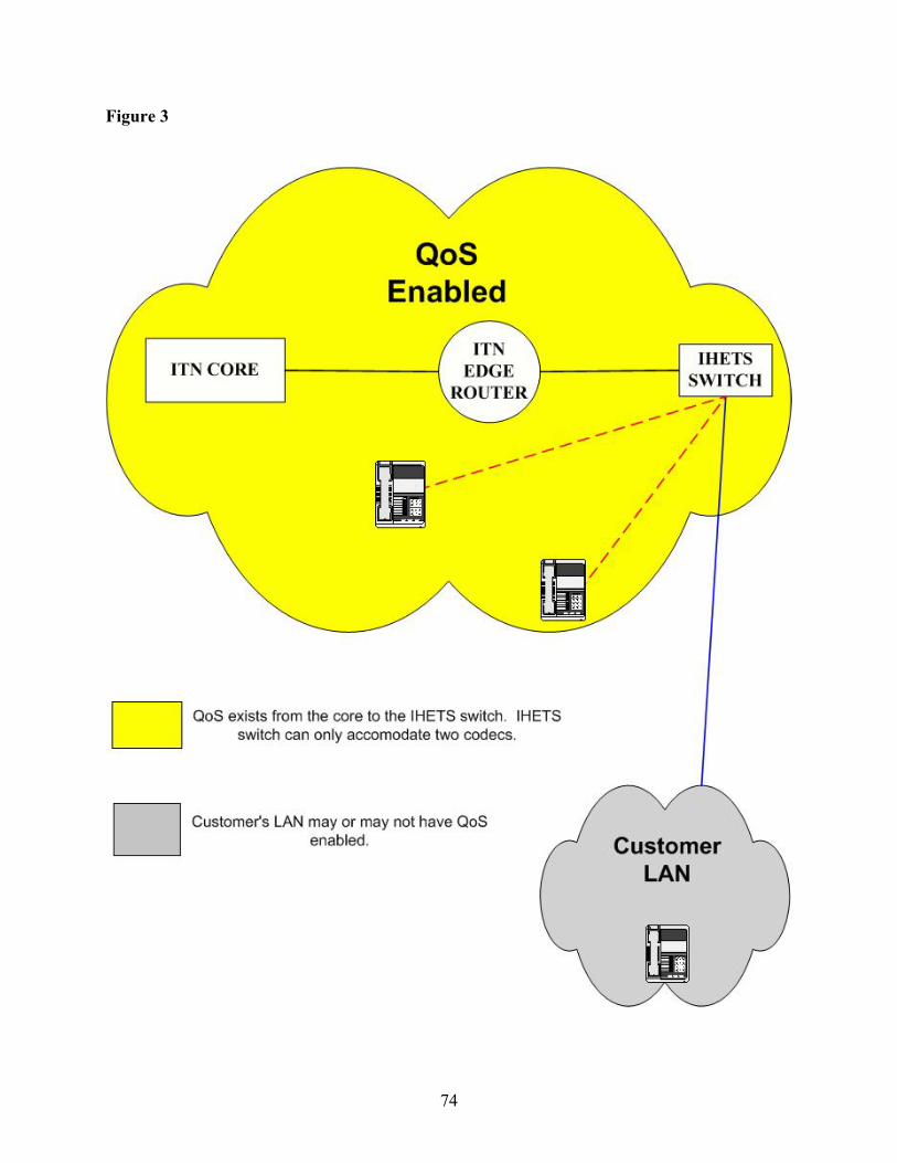
Figure 3
74

Figure 4
75

LAN Issues Many factors come into play in implementing QoS, not least of which is the LAN. While ITN can design a network that will provide QoS out to the LAN interface on the router, individual LAN administrators will have to consider how to allocate resources for voice, video, and data. Some of these issues are:
• How much of the existing bandwidth is still free? • Am I using 100Mbps Switched Ethernet throughout the entire LAN? • Am I using DSCP/IP Precedence to separate voice and video traffic into a Priority Queue
and the rest of the traffic into a Weighted Round Robin (WRR) queue? • If my switch does not have two queues, am I using WRR for all classes? • Have I gotten rid of all of my shared hubs where telephony is concerned? • How bursty is my LAN? • Can the LAN switches and routers support 100 Mbps/Full Duplex (Best), 10 Mbps/Full
Duplex (better), or only 10 Mbps/Half Duplex? • Will desktops doing telephony and video conferencing overload the LAN?
These are some of the questions that the network LAN designers will have to consider as they implement IP telephony on their networks. Steps Necessary to Implement QoS on a Cisco Empowered Wide Area Network Creating the Arena Before implementing QoS, engineers must first establish an environment within the hardware making differentiated services possible. The equipment providing this environment must have adequate processor, memory, and back-plane resources. A very common problem, which must be corrected before implementing a working QoS solution, is Head-Of-Line-Blocking or HOLB. This issue is present in virtually all of the Cisco routing platforms on the market today. HOLB comes into play on devices that do not use SSB (Single Stage Buffering). The issue presents itself when the output queues on an egress interface become exhausted and the hardware is unable to offload the input queue on the ingress interface. During this state of the problem, randomized delay is induced to the traffic stream. If this activity continues, the input queues on the ingress interface will become exhausted, thus causing an aborted or ignored data gram. At this stage of the problem, data grams (see Figure 5) are being discarded randomly and may not even belong to the interface causing the problems.
76

Figure 5
A technique allowing the Cisco routing platform to work around this design issue includes limiting the transmit queues, limiting the hold queues, and applying Committed Access Rates (CAR) to ALL interfaces on the chassis. (Cisco Express Forwarding (CEF) must be enabled before the functional use of CAR.) A successful implementation of these changes will not allow the initial overflow of the output buffer, which cures HOLB before it starts.
Using the 7200 VXR series as an example, the following commands would be issued to the device:
Tx-ring-limit 12 Hold-queue 30 out Rate-limit output X Y Z conform-action transmit exceed-action drop Where X 95% of capacity Y Normal Burst Bytes Z Maximum Burst Bytes
Implementing QoS Creating a QoS or CoS on a Cisco routing platform is simply done by creating a service policy and applying the policy to the output side of the interface. Service policies can range from very simple prioritizations to complex queuing issues. This particular example will describe a service policy using the low-latency queuing (LLQ) feature set, which supports prioritized traffic (typically voice and/or video) and allows further granularity to differentiate between groups of data applications (gold, silver, bronze, etc.). LLQ is essentially a (PQ) enabled Custom Queue (CQ) with Weighted Random Early Detection (WRED).
77

A Custom Queue is simply a queue strategy that is customized to meet the needs of the implementation. An example would be defining a queue that treats IPX traffic preferably over SNA. A Priority Queue is a queue that has the capability to service traffic that matches a certain criterion before other traffic is serviced. This is a necessity to applications that are sensitive to jitter and delay variation. This queue should be less than 33 percent of the capacity of the connection that it services, thus giving the queue the ability to prioritize and interleave traffic. The example provides 10kbs of ‘RAS’ or call-control traffic, 512kbs of low-latency Priority Queue, and the remainder to traffic based upon IP Precedence values 0 thru 3. Traffic with the Precedence value of 0 is 12.5 times more likely to be dropped than Precedence 4 traffic. Policy assumptions before implementation: Define “Priority” traffic as any traffic with the IP Precedence value of 5. Define “RAS” traffic as anything flowing on UDP/TCP ports 1718-1720 and UDP ports 54000-56000. Configuring the Router: Defining RAS: Class-map match-all ras Match access-group 2222 Access-list 2222 permit udp any any range 1718 1720 CHECK PORTS Access-list 2222 permit udp any range 1718 1720 any Access-list 2222 permit tcp any any range 1718 1720 Access-list 2222 permit tcp any range 1718 1720 any Access-list 2222 permit udp any range 54000 56000 any Access-list 2222 permit udp any any range 54000 56000 Defining Priority: Class-map match-all priority Match ip precedence 5
Building the Policy: policy-map T1 class priority priority 512 class ras bandwidth 10 class default bandwidth 600 random-detect random-detect precedence 0 2 4 4 random-detect precedence 1 2 4 5
78

random-detect precedence 2 2 4 5 random-detect precedence 3 2 4 10 random-detect precedence 4 2 4 50 * In these statements we are increasing the mark probability as the precedence value decreases.
Applying the policy to the interface: Interface X/Y.Z Service-policy T1 out References 1. “Recommendations for the Phase I Deployment of OSI Directory Services (X.500) and OSI Message Handling Services (X.400) within the ESnet Community”, ESCC X.500/X.400 Task Force, ESnet Site Coordinating Committee (ESCC), Energy Sciences Network (ESnet), RFC 1330, May 1992, www.cis.ohio-state.edu/Services/rfc/rfc-text/rfc1330.txt 2. T. Howes, “The Lightweight Directory Access Protocol: X.500 Lite”, July 27, 1995, www.stanford.edu/group/networking/directory/doc/ldap/ldap.html. 3. “The SLAPD and SLURPD Administrators Guide, Release 3.3”, University of Michigan, April 30, 1996, www.umich.edu/~dirsvcs/ldap/doc/guides/slapd/toc.html 4. W. Yeong, T. Howes, S. Kille, “Lightweight Directory Access Protocol”, RFC 1777, March 1995, www.cis.ohio-state.edu/cgi-bin/rfc/rfc1777.html 5. “Click To Meet and NAT/Firewall Solving the Security Dilemma”, First Virtual Communications, Inc., 31 May 2001. 6. G. Scheichl, “Using Click to MeetTM with the Cisco MCM and IP/VC 3500 Series Products”, Version 1.0 Application Note, First Virtual Corporation, Inc., 12 June 2001, www.fvc.com//products/whitepapers.htm
7. Cisco IP Telephony Network Design Guide, Cisco Call Manager Release 3.0(5), Cisco Systems, Inc, 2001, www.cisco.com/univercd/cc/td/doc/product/voice/ip_tele/avvidqos/index.htm
8. Implementing a Wide Area Network, Cisco Systems, Inc., Copyright© 1992-2001, www.cisco.com/univercd/cc/td/doc/product/voice/ip_tele/avvidqos/qoswan.htm#xtocid1116739
9. Deploying QoS for Voice and Video in IP Networks, Networkers Session VVT-213, Copyright © 1998, Cisco Systems, Inc., www.cisco.com/networkers/nw01/pres/preso/VideoandVoiceTechnologies/VVT-213.pdf
79

10. Designing and Deploying IP Videoconferencing, Enterprise Solutions Engineering, Networkers Session VVT-230, Copyright© 2000, Cisco, Systems, Inc., www.cisco.com/networkers/nw01/pres/preso/VideoandVoiceTechnologies/VVT-230.pdf
11. Quality-Of-Service, Random Early Detection (RED), Cisco Systems Inc., 1992-1999, www.cisco.com/warp/public/732/Tech/red
80

Equipment Testing Equipment testing is a vital phase of any evaluation of a product being considered for implementation. For the test each vendor sent their engineers to help with implementation of their equipment. Below we profile two vendors: Avaya and Mitel
1. Integrated Avaya IP Telephony Solutions - Ball State University (BSU) 2. A deployment of 32 phones integrating with a Mitel system - Indianapolis Marion
County Public Library 1. Avaya North American Communications Resource (NACR) installed the Avaya IP telephony product for testing in early November 2002. The platform consisted of a G700 gateway and an S8300 media server. Several styles of IP phones were provided and deployed through the IHETS offices. The gateway was connected to the PSTN through a PRI and the IP phones were connected to the media server through a spare Ethernet switch. The IP phone instruments functioned well and had excellent call quality at both 64 Kbps and 8 Kbps codec rates. Complete testing of call quality under bandwidth restricted conditions was unable to be completed due to technical issues with IHETS equipment and Avaya’s request not to reconnect their equipment unless it was behind a firewall. The G700 Media Gateway was connected to the PSTN through a PRI to support inbound and outbound local dialing. The IP phones were connected to the Media Server through a spare Ethernet switch. The connection to the Internet was through this same switch. Ball State University has done some work to IP enable their Avaya PBX. It was determined that the hardware was in place between Ball State and IHETS and the software could be added to create VoIP trunking between the two switches. NACR, Avaya, and IHETS engineers attempted to make the gateway configurations between the Ball State University Avaya Switch and the IHETS G700 Media Gateway necessary to allow for VoIP trunking. The connection had problems and was never made functional. 2. Mitel 3300 series IP telephony product Information Management Group (IMG) brought the Mitel IP telephony PBX system into IHETS for testing. The 3300 product consists of a series of one rack unit high chassis connected together to create a PBX system of up to 40,000 stations. One 3300 chassis deals with the IP station registration connectivity while another chassis deals with PSTN connectivity in any of the various forms, T1/D4, PRI, BRI, and analog. The basic 3300 chassis supports voicemail, ACD, and unified messaging.
81

It was found that the call quality of the Mitel stations was excellent under normal loading conditions. Bandwidth restrictions were introduced on the Ethernet connection between the 3300 and the Mitel stations to test the effect of traffic loading on voice quality. The bandwidth was limited to 250 Kbps. The Mitel system uses a “zone” concept to establish what level of compression will be used in various parts of the total network. The Mitel stations were set for 8 Kbps codec. Calls worked fine station-to-station with no apparent loss of call quality but station-to-station call packets were not passing through the band-limiting filter under our configuration. Call attempts were then made out to the PSTN and back into Mitel stations to create call traffic that could pass through the band-limiting filter. Establishing one call out and back in worked fine but making the second call out and back in would disrupt all the call traffic to the point of making all the conversations unusable. Four 8 Kbps call paths should not have generated this much traffic, so IMG was consulted to assist in correcting the issue. IMG advised that the Mitel product would always use a 64 Kbps codec when connecting to the PSTN irrespective of how the “zone” is configured. The Mitel IP phone uses over 96 Kbps of bandwidth while running the 64 Kbps codec. Bandwidth limited testing at 64 Kbps was not done because of the above results. Indianapolis Marion County Public Library had talked with IMG about the Mitel product and deployed some stations for testing prior to IMG testing at IHETS. IHETS took advantage of that deployment and the WAN connection to IMCPL to test Mitel’s ability to establish VoIP connectivity across the WAN. Additional software keys had to be obtained for the equipment located at IMCPL. Connectivity for one station at IMCPL was established between IHETS and IMCPL using four-digit dialing. Voice quality was excellent.
82

Pilot Projects
In the developing stages of a service, pilot projects are done to determine if the equipment selected will work in the manner required. IHETS conducted two pilot projects over the course of several months with some of the task force members. There were two Pilot Projects conducted:
1. HETS Implementation – This was a forklift implementation replacing a PBX with a fully functional Cisco Avvid IP Telephony system into a production environment.
2. Family and Social Services Administration (FSSA)/Indiana Department of
Transportation (INDOT) – This connected a public to private network using Nortel systems telephony solution.
1. IHETS Implementation In August 2002, IHETS implemented Cisco Call Manager (CCM) in combination with the CIC (Customer Interaction Center) server from Interactive Intelligence. The IHETS install consisted of 94 phones and unified messaging for all users. In addition to internal users, Call Manager will process roughly 600,000 minutes a month in traffic for SUVON. SUVON is a private dial-plan that currently facilitates long-distance between 89 Indiana based college and university campuses. IHETS facilitates off-net calls into the Indianapolis area. If a user at another campus places a call to a location in the Indianapolis calling area, that call will be routed inbound on the SUVON network and tandem routed outbound via the local exchange carrier. This provides a toll-bypass feature. Call Manager provides an avenue for the integration of the IHETS office, SUVON, and the VoIP network more seamlessly. The advantage to IHETS with Call Manager is that the ITN or Indiana Telecommunications Network is primarily a Cisco network. IHETS can take advantage of existing routers already in place that can be setup as voice “gateways” using either H.323 or MGCP. H.323 is used when only “toll-bypass” is needed, while MGCP is applied to sites that need to be “survivable” and/or need fully featured IP phones. Another consideration that IHETS had in choosing an IP PBX is the Help Desk for the Indiana Telecommunications Network (ITN). The Help Desk is a 24-7 operation that provides first-level support for the ITN customer base. This need is facilitated via Call Manager and the CIC server. Inbound calls are routed to Call Manager and in-turn routed to CIC. Once CIC has the call in a queue, it will check the status of available agents and route the call accordingly. CIC is also the platform that was chosen for unified messaging and IVR functionality for IHETS. The benefit that immediately presented itself is that CIC can facilitate ACD, IVR, and unified messaging on one server. CIC can be clustered for failover purposes and helps eliminate provisioning multiple servers to facilitate each individual need.
83

2. FSSA/INDOT IHETS and Nortel Networks setup an IP telephony test between four locations on the ITN network. The sites involved were Government Center, FSSA East Washington, INDoT Greenfield, and IHETS. (See Appendix B) The purpose of the test was to get exposure to the Nortel Networks IP technology products and overcome ITN network configuration issues. The ITN network presented some unusual challenges because all state IP traffic uses private IP addresses and sits behind a firewall while IHETS uses public IP space. The state has very strict regulations about what will be allowed through their firewall, so the firewall could not be opened for IP telephony testing. Two IP PBXs were installed to solve the firewall issue, with voice trunking between them. Nortel Networks engineers brought in the IP telephony equipment and spent several days configuring it to fit the network. The equipment consisted of a Succession CES 1000 Release 2 Communication Server, which provided IP connectivity for the IP phones at the Government Center and FSSA, a Meridian Option 11C Mini PBX trunked to INDoT Greenfield and a Business Communications Manager (BCM) trunked to the Mini 11C providing IP service for the IHETS IP phones. The INDoT Greenfield office’s PBX was retrofitted with an ITG trunk card to support IP telephony. The Greenfield office used their existing phone sets for the test. Nortel Networks engineers tested the ITN network connectivity between the IHETS facility and the Government Center and found QoS not implemented on the routers. During testing, as many as 40 simultaneous calls were simulated. Some minor dropouts were noted during periods of peek usage. These dropouts were attributed to router queuing. Local dial tone was provided through an ISDN PRI. Twenty DID numbers were available within the PRI in two different NXX groups, 713-0429-0438 and 524-6749-6758. Licensing feature restrictions within the Meridian 11C being used for testing limited setup to only one of the DID NXX groups. The 524 exchange extensions were assigned to the state IP phones as DID and extension numbers. The 713 exchange extensions were assigned to the IHETS phones as extension numbers. Greenfield used their existing extension numbers. Four digit extension dialing was implemented between all phones. The IP phones were made available for day-to-day business activities and functioned well. State personnel noticed an occasional distortion but this was expected because of the quality of the cabling being used for some of the phone locations. Restricted bandwidth testing was performed with the phones set to operate using the 8 Kbps codec. It was found that calls could be completed and conversations could be held right up to the point where the number of active calls consumed the available 250 Kbps of bandwidth. No calls were dropped and conversation was possible but varying degrees of distortion existed. The phones were then set to operate using a 64 Kbps codec. The first few calls connected and functioned normally and then the bandwidth limit was reached. Additional calls still connected but several anomalies developed. Ring back would be erratic or nonexistent. Calls that had existed prior to the circuit being overloaded continued to remain connected but call quality
84

became poor to unusable. As calls were disconnected and bandwidth freed up, the remaining calls recovered. A brief overload of the IP circuit did not result in the IP calls being dropped.
85

Business Case for IP Telephony Overview It is widely accepted that IP Telephony is situated as the driving force for the next generation of enterprise telephony systems, since traditional telephony services are reaching the twilight of their lifecycles. Cost savings are but one of the potential benefits to IP Telephony. Industry wide, future costs are expected to continue to drop in the procurement of IP Telephony systems. As the industry standards become more uniform and the volume of systems on the market increase, a downward pressure on system pricing can be expected. Generally, cost justification improves as the potential sites are spread out further from each other through a reduction in toll costs and a reduction in LEC lines. Another benefit can be that the use of new applications will create greater efficiencies and higher productivity. This is one of the primary goals of a converged network and will be discussed at length. Expense recovery opportunities (defined as “decreasing the cost of doing business”) will also be a major factor in the decision to deploy an IP Telephony solution. Innovative opportunities will be more abundant through a converged network, since more rapid deployment of future applications will be possible. Objective One of the primary objectives of the Task Force is to identify a methodology to be used to produce a business case for various IP Telephony applications. This business case methodology is critical to those responsible for evaluating the financial and networking advantages of IP Telephony. The following information points should be considered in creating a business case for your application. Tools Several manufacturers offer Return on Investment (ROI) calculation tools. Nortel Networks, Avaya, and Cisco are a few of the manufacturers to offer the ROI tool. These tools list many of the specific factors that must be evaluated in consideration of an IP Telephony deployment at a given location. The use of the manufacturer’s calculation tools help to provide a checklist of issues to weigh when considering an IP Telephony solution. These calculators provide the ability to change some of the default assumptions built into the tool. For example, one calculator assumes that you will have a 10 percent bandwidth efficiency savings by implementing their IP Telephony solution. This may or may not be the case for your particular institution. Most are available online after registering with the individual manufacturer. Avaya and Mitel requests that you contact the local representative and attach a letter of request in order to access their site. Nortel Networks’s URL is https://transportvo.nortelnetworks.com/SAMLogin. Nortel Networks also requires that the user register through the local representative prior to accessing the site. These tools will require that you input information specific to your institution and its requirements. It should be understood that each of these manufacturers’ calculator tools are based upon their own specific hardware/software solutions. Therefore, none of these provide a generic business model. However, these calculators do provide guidance as to what you might
86

want to consider in constructing a business case customized for your institution’s decision-making process. What do I need to do to use a business case calculator? You must input certain information regarding your institution. These include such things as staff, facilities, your current telephony solution, and future required functionality. Below are some examples of the various input factors used by different vendors: Moves/Adds/Changes
• • • •
• • •
•
• •
Number of employees Estimated number of telephone moves per year Estimated number of staff additions Estimated number of telephone change requests
Technical Support
Number of technical support persons currently assigned to telephony and data Annual fully loaded labor rate per support person Since all traffic, voice, video, and data, is on a unified converged network, a reduction in staffing requirements may be possible. Since the numbers of networks are being reduced from three to one, it stands to reason that fewer personnel would be required to maintain the network.
In Building Wiring
The percent of technician time spent maintaining wiring in a cross-connection panel Life Cycle Management
Input the average life expectancy of current data network equipment Input the average life expectancy for the current telephony system
Bandwidth Consideration This is a calculation based upon your total network expenditure. The concept is that by consolidating or converging email, data, voice, video, and fax onto the same circuit, this may result in a reduction of LEC lines to the Public Switched Telephone System (PSTN). For institutions with multiple locations, there may be a reduction in long distance toll charges.
Integration of Existing Components These fields are used to estimate the replacement cost of your current equipment. This deals more with cost avoidance than with cost savings. You may be asked to estimate the replacement cost of your PBX, voicemail, and data equipment. What is certain is that the factors for each location will be different and therefore will have to be evaluated according to their own merit. Among the factors to be considered are the infrastructure elements: moves, adds, and changes, (m/a/c); bandwidth consolidation, current and future network support, lifecycle management, wiring consolidation, and integration of existing components.
87
88
Among the applications to be evaluated are: Unified Messaging (UM) centralized voice mail, IP Telecommuters, Integrated Call Center (ICD), and integrated and Web-managed applications. IP enabled applications and their advantages are a primary reason to consider this type of solution. There are generally two types of approaches to implementing IP Telephony. First is the migration approach. The migration approach will follow a gradual path to full IP Telephony implementation. The idea is that some existing equipment may still have useful service life left, and may be capable of allowing for some of the benefits of VoIP to be realized. For example, if you have existing telephony core equipment that may be IP enabled, you may be able to implement VoIP and still use existing Analog or digital phone sets. In this approach you still may be able to realize the benefit of toll bypass and a reduction of LEC lines serving the facility. What you have done is establish a migration path while still leveraging as much value as possible from existing equipment expenditures. The second approach is the “forklift” style approach. This is where the combined factors would dictate that a full IP Telephony solution should be implemented from the start. Naturally, the forklift approach has a higher up-front cost, but also realizes other immediate benefits. With a full IP Telephony deployment Unified Messaging (UM) and its associated benefits are available. Additionally, moves, adds, and changes would add to efficiency by the phone sets being plug and play ready.
Potential Application Benefits Benefits from applications will come from personal productivity and infrastructure savings, plus an increase in customer service efficiency. For example, Unified Messaging may allow an institution to reduce the number of fax machines and fax lines. UM will also enable employees that have access to high bandwidth connections such as cable or DSL to telecommute. The remote employee has the same availability and benefits working from home as they would at the office. The IP Phone (handset or Softphone) will give them the same features and functionality as at the office, including the same telephone number. An area for potential productivity savings would come from an integrated call center. IP Telephony allows for closer integration with the Call Center to database, such as screen pops or other data applications. This integration allows for greater productivity savings. There are also potential savings in eliminating conference bridge equipment as well as labor savings. There are service enhancements to be gained from some applications such as a Web enabled contact center, which allows for efficient distribution of user calls to the appropriate person with the expertise to answer a particular question.
Unified Network Management There are savings from not having to maintain separate directories and from managing from a single location, both voice and data. These should result in more network administration, data administration, and end user productivity and efficiency.