ipc-602 manual ed.3 - advantechadvdownload.advantech.com/productfile/downloadfile1/1-o8... ·...
TRANSCRIPT
IPC-602
2U 6-slot Industrial Rackmount Chassis
User�s Manual

Copyright Notice
This document is copyrighted, September 2004, by Advantech Co., Ltd. All rights are reserved. Advantech Co., Ltd. reserves the right to make improvements to the products described in this manual at any time with-out notice.No part of this manual may be reproduced, copied, translated or transmit-ted in any form or by any means without the prior written permission of Advantech Co., Ltd. Information provided in this manual is intended to be accurate and reliable. However, Advantech Co., Ltd. assumes no responsibility for its use, nor for any infringements upon the rights of third parties which may result from its use.Acknowledgements:� Intel®, Pentium® 4, and Celeron® are trademarks of Intel Corporation.� IPC-602, PCA-6105P4V, PCA-6106P3V, PCA-6106P3VX and PCA- 6106P4V are trademarks of Advantech Co., Ltd.All other product names or trademarks are the properties of their respec-tive owners.On-line Technical SupportFor technical support and service, please visit our support website at:http://www.advantech.com/support
Part No. 2002060201 3rd. Edition
Printed in Taiwan September 2004
IPC-602 User�s Manual ii
A Message to the Customer Advantech customer services
Each and every Advantech product is built to the most exacting specifica-tions to ensure reliable performance in the harsh and demanding condi-tions typical of industrial environments. Whether your new Advantech equipment is destined for the laboratory or the factory floor, you can be assured that your product will provide the reliability and ease of operation for which the name Advantech has come to be known.Your satisfaction is our primary concern. Here is a guide to Advantech�s customer services. To ensure you get the full benefit of our services, please follow the instructions below carefully.
Technical support
We want you to get the maximum performance from your products. So if you run into technical difficulties, we are here to help. For the most fre-quently asked questions, you can easily find answers in your product doc-umentation. These answers are normally a lot more detailed than the ones we can give over the phone.
So please consult this manual first. If you still cannot find the answer, gather all the information or questions that apply to your problem, and with the product close at hand, call your dealer. Our dealers are well trained and ready to give you the support you need to get the most from your Advantech products. In fact, most problems reported are minor and are able to be easily solved over the phone.
In addition, free technical support is available from Advantech engineers every business day. We are always ready to give advice on application requirements or specific information on the installation and operation of any of our products.
iii

Product warranty Advantech warrants to you, the original purchaser, that each of its prod-ucts will be free from defects in materials and workmanship for two years from the date of purchase.
This warranty does not apply to any products which have been repaired or altered by persons other than repair personnel authorized by Advantech, or which have been subject to misuse, abuse, accident or improper instal-lation. Advantech assumes no liability under the terms of this warranty as a consequence of such events.
If an Advantech product is defective, it will be repaired or replaced at no charge during the warranty period. For out-of-warranty repairs, you will be billed according to the cost of replacement materials, service time and freight. Please consult your dealer for more details.
If you think you have a defective product, follow these steps:Step 1. Collect all the information about the problem encountered. (For
example, type of PC, CPU speed, Advantech products used, other hardware and software used, etc.) Note anything abnormal and list any on-screen messages you get when the problem occurs.
Step 2. Call your dealer and describe the problem. Please have your man-ual, product, and any helpful information readily available.
Step 3. If your product is diagnosed as defective, obtain an RMA (return material authorization) number from your dealer. This allows us to process your return more quickly.
Step 4. Carefully pack the defective product, a fully-completed Repair and Replacement Order Card and a photocopy proof of purchase date (such as your sales receipt) in a shippable container. A prod-uct returned without proof of the purchase date is not eligible for warranty service.
Step 5. Write the RMA number visibly on the outside of the package and ship it prepaid to your dealer.
IPC-602 User�s Manual iv

Initial Inspection Before you begin installing your backplane, please make sure that the fol-lowing materials have been shipped:� IPC-602 Chassis� User's Manual� Warranty card� Accessory package with screws for disk drives and backplane, a pair of
keys and a spare filterIf any of these items are missing or damaged, contact your distributor or sales representative immediately. We have carefully inspected the IPC-602 mechanically and electrically before shipment. It should be free of marks and scratches and in perfect working order upon receipt. As you unpack the IPC-602, check it for signs of shipping damage. (For example, damaged box, scratches, dents, etc.) If it is damaged or it fails to meet the specifications, notify our service department or your local sales represen-tative immediately. Also notify the carrier. Retain the shipping carton and packing material for inspection by the carrier. After inspection, we will make arrangements to repair or replace the unit.
v

IPC-602 User�s Manual vi

ContentsChapter 1 General Information ........................................2
1.1 Introduction ....................................................................... 21.2 Specifications .................................................................... 2
1.2.1 Passive Backplane Options............................................. 21.2.2 Power Supply Options .................................................... 31.2.3 Environmental specifications.......................................... 3
1.3 Dimensions........................................................................ 4Figure 1-1:Dimension Diagram...................................... 4
1.4 Safety Precautions ............................................................ 5Chapter 2 System Setup.....................................................8
2.1 Introduction ....................................................................... 82.2 Removing the Cover.......................................................... 8
Figure 2-1:Removing the cover ...................................... 82.3 Installing Disk Drives....................................................... 9
Figure 2-2:Installing disk drives .................................... 92.4 Installing Plug-in Cards................................................... 10
Figure 2-3:Installing plug-in cards ............................... 102.5 Replacing the Fan............................................................ 11
Figure 2-4:Replacing the fan ........................................ 112.6 Replacing the Filter ......................................................... 11
Figure 2-5:Replacing the filter...................................... 122.7 Installing the L form holder ............................................ 12
Figure 2-6:L form holders............................................. 12
Appendix A Optional Passive Backplanes........................14A.1 PCA-6105PV4: 4 PCI / 1 CPU slots ............................... 14A.2 PCA-6106P3V: 1 ISA / 3 PCI / 2 PICMG slots.............. 16A.3 PCA-6106PV4: 1 ISA / 4 PCI / 1 CPU slots................... 18
Appendix B Parts Ordering Guide ...................................22Appendix C Safety Instructions .........................................26
C.1 English............................................................................. 26C.2 German - Wichtige Sicherheishinweise .......................... 27
vii

AIMB-744 User�s Manual viii

1
CH
AP
TE
R 1General Information

Chapter 1 General Information1.1 Introduction
The IPC-602 is a compact rugged 19" 2U-height rackmount chas-sis designed for space-limited application. With its rugged, sturdy and well-cooled steel chassis specially designed to withstand heavy shocks and thick dust, the IPC-602 can be used in the harsh-est of environments. It is ideal for Computer Telephony or network system configurations that require high availability within a lim-ited space, such as computer telephony and networking systems.
1.2 Specifications
� Construction: Heavy-duty steel
� Disk drive capacity: One 5.25" and two 3.5" drive bays
� Indicators: LEDs for power On/Off, and HDD
� Controls: Power On and Reset switches on front panel
� Cooling fan: Two 42 CFM fans on front panel, with air filters
� Weight: 8.3 kg (18.26 lbs) without power supply
� Dimensions (W x D x H): 481.2 x 449.5 x 88 mm (19" x 17.7" x 4")
� Interior paint color: Black 2U, 2X; Fabric Texture
1.2.1 Passive Backplane Options
Part Number Slots PC Board IndicatorsPCA-6105P4V 4 PCI / 1 PICMG 6-layer PCB with ground and
power planes for reducing noise and low power-supply imped-ance
LEDs for +5 V, +12 V, -5 V, -12 V, +3.3 V
PCA-6106P4V 1 ISA / 4 PCI / 1 PICMGPCA-6106P3V 1 ISA / 3 PCI / 2 PICMG
IPC-602 User�s Manual 2
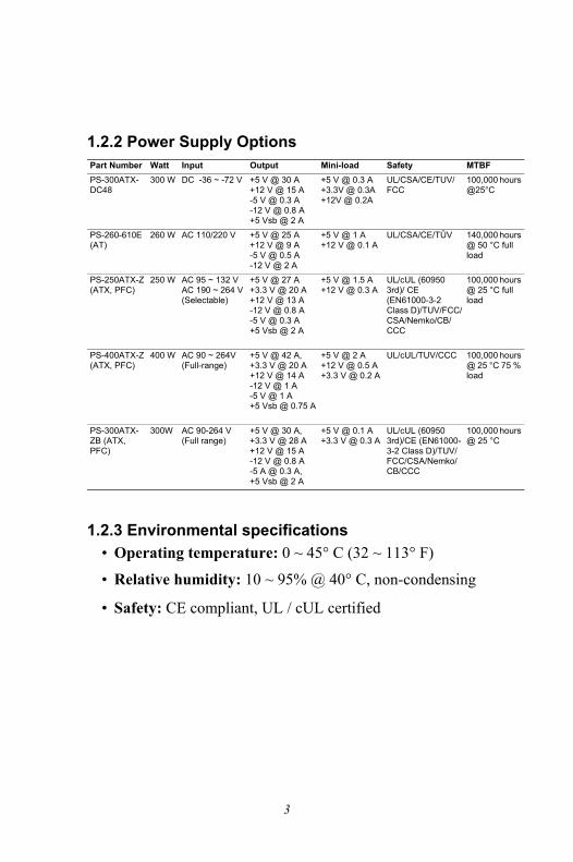
1.2.2 Power Supply Options
1.2.3 Environmental specifications� Operating temperature: 0 ~ 45° C (32 ~ 113° F)
� Relative humidity: 10 ~ 95% @ 40° C, non-condensing
� Safety: CE compliant, UL / cUL certified
Part Number Watt Input Output Mini-load Safety MTBFPS-300ATX-DC48
300 W DC -36 ~ -72 V +5 V @ 30 A+12 V @ 15 A-5 V @ 0.3 A-12 V @ 0.8 A+5 Vsb @ 2 A
+5 V @ 0.3 A+3.3V @ 0.3A+12V @ 0.2A
UL/CSA/CE/TUV/FCC
100,000 hours @25°C
PS-260-610E (AT)
260 W AC 110/220 V +5 V @ 25 A+12 V @ 9 A-5 V @ 0.5 A-12 V @ 2 A
+5 V @ 1 A+12 V @ 0.1 A
UL/CSA/CE/TÜV 140,000 hours @ 50 °C full load
PS-250ATX-Z (ATX, PFC)
250 W AC 95 ~ 132 VAC 190 ~ 264 V (Selectable)
+5 V @ 27 A +3.3 V @ 20 A+12 V @ 13 A-12 V @ 0.8 A-5 V @ 0.3 A +5 Vsb @ 2 A
+5 V @ 1.5 A+12 V @ 0.3 A
UL/cUL (60950 3rd)/ CE (EN61000-3-2 Class D)/TUV/FCC/CSA/Nemko/CB/CCC
100,000 hours @ 25 °C full load
PS-400ATX-Z (ATX, PFC)
400 W AC 90 ~ 264V (Full-range)
+5 V @ 42 A, +3.3 V @ 20 A+12 V @ 14 A-12 V @ 1 A -5 V @ 1 A+5 Vsb @ 0.75 A
+5 V @ 2 A +12 V @ 0.5 A+3.3 V @ 0.2 A
UL/cUL/TUV/CCC 100,000 hours @ 25 °C 75 % load
PS-300ATX-ZB (ATX, PFC)
300W AC 90-264 V (Full range)
+5 V @ 30 A, +3.3 V @ 28 A+12 V @ 15 A-12 V @ 0.8 A -5 A @ 0.3 A, +5 Vsb @ 2 A
+5 V @ 0.1 A+3.3 V @ 0.3 A
UL/cUL (60950 3rd)/CE (EN61000-3-2 Class D)/TUV/FCC/CSA/Nemko/CB/CCC
100,000 hours @ 25 °C
3

1.3 Dimensions
Figure 1-1: Dimension Diagram
unit: mm [inch]
IPC-602 User�s Manual 4

1.4 Safety Precautions
Warning! Always completely disconnect the power cord from your chassis whenever you work with the hardware. Do not make connections while the power is on. Sensitive electronic components can be damaged by sudden power surges. Only experienced electronics personnel should open the PC chassis.
Caution! Always ground yourself to remove any static charge before touching the backplane, mother-board or add-on cards. Modern electronic devices are very sensitive to static electric charges. As a safety precaution, use a ground-ing wrist strap at all times. Place all electronic components on a static-dissipative surface or in a static-shielded bag when they are not in the chassis.
Caution! The computer is provided with a battery-pow-ered Real-time Clock circuit. There is a danger of explosion if battery is incorrectly replaced. Replace only with same or equivalent type rec-ommended by the manufacturer. Discard used batteries according to manufacturer's instruc-tions.
Caution! There is a danger of a new battery exploding if it is incorrectly installed. Do not attempt to recharge, force open, or heat the battery. Replace the battery only with the same or equivalent type recommended by the manufac-turer. Discard used batteries according to the manufacturer�s instructions.
5

This device complies with the requirements in part 15 of the FCC rules: Operation is subject to the fol-lowing two conditions:
1.This device may not cause harmful interference, and
2.This device must accept any interference received, including interference that may cause undesired operation
This equipment has been tested and found to com-ply with the limits for a Class A digital device, pursu-ant to Part 15 of the FCC Rules. These limits are designed to provide reasonable protection against harmful interference when the equipment is oper-ated in a commercial environment. This equipment generates, uses, and can radiate radio frequency energy and, if not installed and used in accordance with the instruction manual, may cause harmful interference to radio communications. Operation of this device in a residential area is likely to cause harmful interference in which case the user will be required to correct the interference at his/her own expense. The user is advised that any equipment changes or modifications not expressly approved by the party responsible for compliance would void the compliance to FCC regulations and therefore, the user's authority to operate the equipment.
IPC-602 User�s Manual 6

7 Chapter 2
CH
AP
TE
R 2System Setup
Chapter 2 System Setup2.1 Introduction
The following procedures are provided to assist you in installing drives and plug-in cards into the IPC-602.
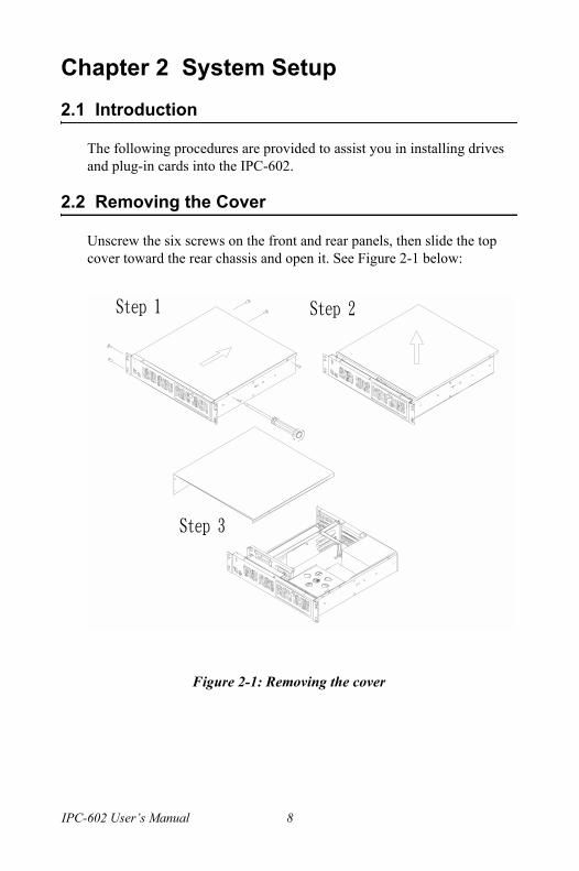
2.2 Removing the Cover
Unscrew the six screws on the front and rear panels, then slide the top cover toward the rear chassis and open it. See Figure 2-1 below:
Figure 2-1: Removing the cover
IPC-602 User�s Manual 8

2.3 Installing Disk Drives
After removing the cover, you can easily install disk drives. Please refer to Figure 2-2 below and do the following:1. Remove the four outer screws which mount the drive bay to the chassis.2. Slide the drive bay backwards to a location where it is not obstructed by the top rim. Lift it free from the chassis.3. Remove the front cover of the drive bay, and insert the drives into the proper locations in the drive bay.4. Put back the drive bay properly and fasten the screws.
Figure 2-2: Installing disk drives
9 Chapter 2

2.4 Installing Plug-in Cards
After removing the cover, you can easily install plug-in cards by follow-ing the steps. Please refer to Figure 2-3 below:1. Unscrew the screws on the card cage.2. Insert the CPU card carefully into the PICMG slot and then fix it by
screwing it into the card bracket. You can also fix the other edge of the CPU card using the supplied small L-form holder.
3. If users need to insert other cards on the other side of the backplane, please loosen the L-form support first. After installing the cards, also fix them to the card cage by screwing them into the card bracket. Then replace the L-form support and fasten it.
4. After all cards are installed completely, put card cage back into the correct location in the chassis. Finally, fasten the screws.
Figure 2-3: Installing plug-in cards
IPC-602 User�s Manual 10

2.5 Replacing the Fan
1. Unscrew the two screws on the fan bracket, and slide the bracket back-wards. See Figure 2-4 below:2. Replace the new fan and fix it to the bracket. 3. Put back the fan bracket and fasten the screws.
Figure 2-4: Replacing the fan
2.6 Replacing the Filter
The filter is located next to the lockable door. If IPC-602 is under use constantly, the filter should be changed about once a month. To replace the filter, refer to Figure 2-5 below and do the following:1. Open the lockable door.2. Remove the filter by gently pulling the tab and sliding the filter rightwards.3. Slide a new filter in until it snaps into place.4. Close and lock the lockable door.
11 Chapter 2
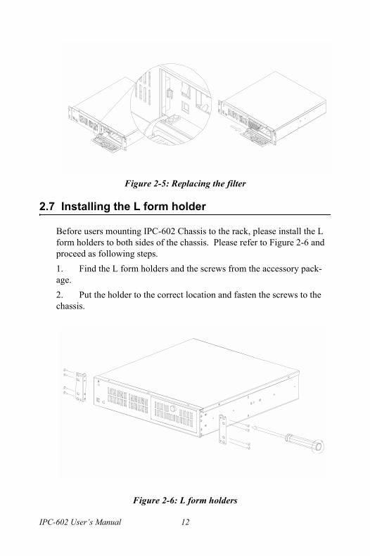
Figure 2-5: Replacing the filter
2.7 Installing the L form holder
Before users mounting IPC-602 Chassis to the rack, please install the L form holders to both sides of the chassis. Please refer to Figure 2-6 and proceed as following steps.1. Find the L form holders and the screws from the accessory pack-age. 2. Put the holder to the correct location and fasten the screws to the chassis.
Figure 2-6: L form holders
IPC-602 User�s Manual 12

13 Appendix A
Appendix A
Optional Passive Backplanes

Appendix A Optional Passive BackplanesA.1 PCA-6105PV4: 4 PCI / 1 CPU slots
Dimensions: 260 x 80 mm
1. Connectors
Connector DescriptionCPC1 PICMG connectorsPCI 1~4 32 bit PCI BUS connectors (primary)CN2 8-PIN +12V, -12V, +3.3V, +5V, -5V, GND and 5VSB connectorCN1 3-PIN PS_ON, GND and 5VSB for ATX powerCN3 3-PIN +12V, GND and +5V DC power connectorKB1 To CPU card K/B connectorKB3 To front part K/B connectorATX1 ATX Power connector
IPC-602 User�s Manual 14
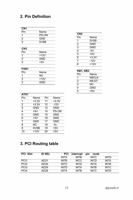
2. Pin Definition
3. PCI Routing table
CN1Pin Name1 PS-ON2 GND3 5VSB
CN3Pin Name1 +12V2 GND3 +5V
FAN1Pin Name1 NC2 +12V3 GND
ATX1Pin Name Pin Name1 +3.3V 11 +3.3V2 +3.3V 12 -12V3 GND 13 GND4 +5V 14 PS-ON5 GND 15 GND6 +5V 16 GND7 GND 17 GND8 NC 18 -5v9 5VSB 19 +5V10 +12V 20 +5V
CN2Pin Name1 5VSB2 GND3 GND4 -5V5 +5V6 +3.3V7 -12V8 +12V
KB1, KB3Pin Name1 KBCLK2 KB-DT3 NC4 GND5 +5V
PCI Slot ID SEL PCI interrupt pin routeINTA INTB INTC INTD
PCI1 AD31 INTB INTC INTD INTAPCI2 AD30 INTC INTD INTA INTBPCI3 AD29 INTD INTA INTB INTCPCI4 AD28 INTA INTB INTC INTD
15 Appendix A

A.2 PCA-6106P3V: 1 ISA / 3 PCI / 2 PICMG slots
Dimensions: 260 x 80 mm
1. Connectors
Connector DescriptionISA1, ISA3 ISA connector for PICMG slot (PCI slot is
PICMG1,PICMG3)ISA2 ISA connector PICMG1,PICMG2 PCI connector for PICMG slotPCI1~PCI3 32 bit PCI slotVKB1 KB-In, from CPU card K/B connector VKB2,VKB3 KB-Out, 5 pin external K/B connector VAT1 AT power connector 90DVATX1 ATX Power connector 90DHCN1 PS-ON Function, to CPU card for ATX Power signal, 3 pin
connector HCN2 8 pin Alarm Board Power connector HCN3 3 pin +5V and +12V Power connector
CN2
CN3
CN1
KB1
KB3
D18
1
11
ATX 10
20
+12PG +5V -12 GNDP8-P9
+5V-5V
160 8.13
61.4
7
73.2
8
260
80
32.89
20.3
220
.32
18.2
9
No circuit area
3
No circuit area
84.8
15.875
20.3
220
.32
22.1
115.62
12 15
21
33
21
12.9
12
15
IPC-602 User�s Manual 16

2. Pin Definition
3. PCI Routing table
VKBA1,VKBA2,VKBA3;Pin Name1 KBCLK2 KBDATA3 NC4 KBGND5 KBVCC
HCN1Pin Name1 PS-ON2 GND3 5VSB
HCN2Pin Name1 5VSB2 GND3 GND4 -5V5 +5V6 +3.3V7 -12V8 +12V
HCN3Pin Name1 +12V2 GND3 +5V
VATX1Pin Name1 +3.3V2 +3.3V3 GND4 +5V5 GND6 +5V7 GND8 NC9 5VSB10 +12V11 +3.3V12 -12V13 GND14 PS-ON15 GND16 GND17 GND18 -5V19 +5V20 +5V
VAT1Pin Name1 NC2 +5V3 +12V4 -12V5 GND6 GND7 GND8 GND9 -5V10 +5V11 +5V12 +5V
PCI Slot ID SEL PCI interrupt pin routeINTA INTB INTC INTD
PCI1 AD30 INTC INTD INTA INTBPCI2 AD29 INTD INTA INTB INTCPCI3 AD28 INTA INTB INTC INTD
17 Appendix A

A.3 PCA-6106PV4: 1 ISA / 4 PCI / 1 CPU slots
Dimensions: 260 x 80 mm
1. ConnectorsConnector DescriptionISA1~ISA2 16 bit ISA Bus connectorPPCI1~PPCI4 32 bit PCI Bus connector (Primary Group)PICMG1 PICMG connectorATX1 ATX Power connectorKB1 KB-In, from CPU card K/B connectorKB2~KB3 KB-Out, 5 pin external K/B connectorCN1 PS-ON Function, to CPU card for ATX power signal, 3 pin CN2 8 pin Alarm Board Power connectorCN3 8 pin +5V and +12V FAN connector
IPC-602 User�s Manual 18
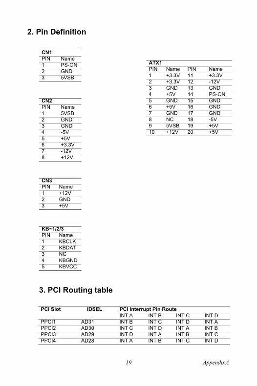
2. Pin Definition
3. PCI Routing table
CN1PIN Name1 PS-ON2 GND3 5VSB
CN2PIN Name1 5VSB2 GND3 GND4 -5V5 +5V6 +3.3V7 -12V8 +12V
CN3PIN Name1 +12V2 GND3 +5V
KB~1/2/3PIN Name1 KBCLK2 KBDAT3 NC4 KBGND5 KBVCC
ATX1PIN Name PIN Name1 +3.3V 11 +3.3V2 +3.3V 12 -12V3 GND 13 GND4 +5V 14 PS-ON5 GND 15 GND6 +5V 16 GND7 GND 17 GND8 NC 18 -5V9 5VSB 19 +5V10 +12V 20 +5V
PCI Slot IDSEL PCI Interrupt Pin RouteINT A INT B INT C INT D
PPCI1 AD31 INT B INT C INT D INT APPCI2 AD30 INT C INT D INT A INT BPPCI3 AD29 INT D INT A INT B INT CPPCI4 AD28 INT A INT B INT C INT D
19 Appendix A

IPC-602 User�s Manual 20

21 Appendix B
Ap
pe
nd
ix BParts Ordering Guide

Appendix B Parts Ordering Guide
Code Part No. Q�ty Description Code Part No. Q�ty Description1 1960000404 1 TOP COVER 22 1995000090 1 FILTER HOUS-
ING2 1902610682 1 BACKPLANE
BASE23 199902K000 1 FILTER PE
3 1960000444 1 CHASSIS 24 1992601085 1 LOCK SETS4 1962011390 1 5.25� DISK
COVER25 1960000445 1 FRONT PLATE
5 1962650600 1 3.5� DISK COVER
26 1962002810 1 LOCKABLE DOOR
6 1962002760 1 DISK DRIVE HOUSING
27 1759400200 1 SPEAKER
7 1962002740 2 HDD BRACKET
28 1962002700 2 LED LAMP HOLDER
8 9686610603 1 BACKPLANE 29 1994000060 2 LED HOUSING9 1962002730 1 FAN
BRACKET30 1 HDD
10 1759081200 2 DUAL FAN 31 1962011510 1 PCI CARD BRACKET
11 9692A10000 1 PS/2 K/B & USB PCB
32 196202K130 1 CPU CARD HOLDER
12 199902K000 1 FILTER PE13 1995000090 1 FILTER
HOUSING
IPC-602 User�s Manual 22

Accessory Options
Ordering Information
14 1653104030 1 ATX POWER SUPPLY
Code Part No. Q�ty Screw Descrip-tion
15 1703020550 1 WIRE MOUNT HOLE
A 193900036 16 HEX/W M3x0.5x5L
16 1601000001 1 RESET BUT-TON
B 1939006320 8 HEX/W#6-32
17 1602002100 1 POWER SWITCH
C 1935330400 6 R/W M3x0.5x5L
18 1962002770 2 SIDE FIXING HOLDER
D 0939000410 8 R/W M4x0.7x5L
19 1962002790 1 FRONT WIN-DOW
E 1930030500 17 FLAT M3x0.5x5L
20 1962002800 1 BEZEL F 1931040620 8 FLAT M4x0.7x5L21 1962610130 2 HINGE G 1939000515 8
Part Number Descriptions SCD-FDD-COMBO Storage kit with slim 24X CD-ROM and standard 3.5�
black FDDSCD COMBO 5.25 5.25" compact storage kit with slim 24X CD-ROM and
a 3.5" drive bay for FDD or HDD9684000014 3.5" FDD with black bezel1701400652 HDD cable, ATA 66/100, 45 cm + 20 cm1750000073 Low profile P4 CPU cooler up to 3.2 GHz1759214200 Low profile P4 CPU cooler up to 2.8 GHZ
Part Number With Power Supply With Backplane RegulationIPC-602P3-00PB Without power supply,
with AT switchPCA-6106P3V-0B1 None
IPC-602P3-00XB Without power supply, with ATX switch
PCA-6106P3V-0B1 None
IPC-602P3-25ZB PS-250ATX-Z PCA-6106P3V-0B1 UL, cUL, CEIPC-602P3-26PB PS-260-610E PCA-6106P3V-0B1 UL, cUL, CEIPC-602P3-30ZB PS-300ATX-ZB PCA-6106P3V-0B1 UL, cUL, CEIPC-602P4-00XB Without power supply,
with ATX switchPCA-6105P4V-0B2 None
IPC-602P4-25ZB PS-250ATX-Z PCA-6105P4V-0B2 UL, cUL, CEIPC-602P4-30ZB PS-300ATX-ZB PCA-6105P4V-0B2 UL, cUL, CE
23 Appendix B

IPC-602 User�s Manual 24

25 Appendix C
Ap
pe
nd
ix CSafety Instructions
Appendix C Safety InstructionsC.1 English
1. Read these safety instructions carefully.2. Keep this user's manual for later reference.3. Disconnect this equipment from any AC outlet before cleaning. Do not use liquid or spray detergents for cleaning. Use a damp cloth.4. For plugable equipment, the power outlet must be installed near the equipment and be easily accessible.5. Keep this equipment away from humidity.6. Put this equipment on a reliable surface during installation. Dropping it or letting it fall could cause damage.7. The openings on the enclosure are for air convection. Protect the equip-ment from overheating. DO NOT COVER THE OPENINGS.8. Make sure the voltage of the power source is correct before connecting the equipment to the power outlet.9. Position the power cord so that people cannot step on it. Do not place anything over the power cord. 10. All cautions and warnings on the equipment should be noted. 11. If the equipment is not used for a long time, disconnect it from the power source to avoid damage by transient over voltage.12. Never pour any liquid into an opening. This could cause fire or elec-trical shock.13. Never open the equipment. For safety reasons, the equipment should be opened only by qualified service personnel.14. If any of the following situations arises, get the equipment checked by service personnel:
a. The power cord or plug is damaged.b. Liquid has penetrated into the equipment.c. The equipment has been exposed to moisture.d. The equipment does not work well, or you cannot get it to
work according to the installation reference guide.e. The equipment has been dropped and damaged.f. The equipment has obvious signs of breakage.
IPC-602 User�s Manual 26

15. DO NOT LEAVE THIS EQUIPMENT IN AN UNCONTROLLED ENVIRONMENT WHERE THE STORAGE TEMPERATURE IS BELOW -20° C (-4° F) OR ABOVE 60° C (140° F). THIS MAY DAM-AGE THE EQUIPMENT.The sound pressure level at the operator's position according to IEC 704-1:1982 is equal to or less than 70 dB(A).
DISCLAIMER: This set of instructions is given according to IEC 704-1. Advantech disclaims all responsibility for the accuracy of any state-ments contained herein.
C.2 German - Wichtige Sicherheishinweise
1. Bitte lesen Sie Sich diese Hinweise sorgfältig durch.2. Heben Sie diese Anleitung für den späteren Gebrauch auf.3. Vor jedem Reinigen ist das Gerät vom Stromnetz zu trennen. Ver-wenden Sie Keine Flüssig-oder Aerosolreiniger. Am besten dient ein angefeuchtetes Tuch zur Reinigung.4. Die Netzanschlußsteckdose soll nahe dem Gerät angebracht und leicht zugänglich sein.5. Das Gerät ist vor Feuchtigkeit zu schützen.6. Bei der Aufstellung des Gerätes ist auf sicheren Stand zu achten. Ein Kippen oder Fallen könnte Verletzungen hervorrufen.7. Die Belüftungsöffnungen dienen zur Luftzirkulation die das Gerät vor überhitzung schützt. Sorgen Sie dafür, daß diese Öffnungen nicht abge-deckt werden.8. Beachten Sie beim Anschluß an das Stromnetz die Anschlußwerte.9. Verlegen Sie die Netzanschlußleitung so, daß niemand darüber fallen kann. Es sollte auch nichts auf der Leitung abgestellt werden.10. Alle Hinweise und Warnungen die sich am Geräten befinden sind zu beachten.11. Wird das Gerät über einen längeren Zeitraum nicht benutzt, sollten Sie es vom Stromnetz trennen. Somit wird im Falle einer Überspannung eine Beschädigung vermieden.12. Durch die Lüftungsöffnungen dürfen niemals Gegenstände oder Flüs-sigkeiten in das Gerät gelangen. Dies könnte einen Brand bzw. elek-trischen Schlag auslösen.
27 Appendix C

13. Öffnen Sie niemals das Gerät. Das Gerät darf aus Gründen der elek-trischen Sicherheit nur von authorisiertem Servicepersonal geöffnet wer-den.14. Wenn folgende Situationen auftreten ist das Gerät vom Stromnetz zu trennen und von einer qualifizierten Servicestelle zu überprüfen:a. Netzkabel oder Netzstecker sind beschädigt.b. Flüssigkeit ist in das Gerät eingedrungen.c. Das Gerät war Feuchtigkeit ausgesetzt.d. Wenn das Gerät nicht der Bedienungsanleitung entsprechend funktion-iert oder Sie mit Hilfe dieser Anleitung keine Verbesserung erzielen.e. Das Gerät ist gefallen und/oder das Gehäuse ist beschädigt.f. Wenn das Gerät deutliche Anzeichen eines Defektes aufweist.15. Bitte lassen Sie das Gerät nicht unbehehrt hinten unter -20° C (-4° F) oder oben 60° C (140° F), weil diesen Temperaturen das Gerät zerstören könten.
Der arbeitsplatzbezogene Schalldruckpegel nach DIN 45 635 Teil 1000 beträgt 70dB(A) oder weiger.
DISCLAIMER: This set of instructions is provided according to IEC704-1. Advantech disclaims all responsibility for the accuracy of any statements contained herein.
IPC-602 User�s Manual 28