ipm-1se user's manual - xenyasup.xenya.si/sup/info/ctc/ipm-1se/ipm_1se_man.pdf · ipm-1se...
TRANSCRIPT
USER MANUAL
IPM-1SE TDM Over IP G.703 E1, T1(DS1)

TRADEMARKS Microsoft is a registered trademark of Microsoft Corp. HyperTerminal™ is a registered trademark of Hilgraeve Inc. WARNING: This equipment has been tested and found to comply with the limits for a Class A digital device, pursuant to Part 15 of the FCC Rules. These limits are designed to provide reasonable protection against harmful interference when the equipment is operated in a commercial environment. This equipment generates, uses, and can radiate radio frequency energy and if not installed and used in accordance with the instruction manual may cause harmful interference in which case the user will be required to correct the interference at his own expense. NOTICE: (1) The changes or modifications not expressively approved by the party responsible for compliance could void the user's authority to operate the equipment. (2) Shielded interface cables and AC power cord, if any, must be used in order to comply with the emission limits. CISPR PUB.22 Class A COMPLIANCE: This device complies with EMC directive of the European Community and meets or exceeds the following technical standard. EN 55022 - Limits and Methods of Measurement of Radio Interference Characteristics of Information Technology Equipment. This device complies with CISPR Class A. WARNING: This is a Class A product. In a domestic environment this product may cause radio interference in which case the user may be required to take adequate measures. CE NOTICE Marking by the symbol CE indicates compliance of this equipment to the EMC directive of the European Community. Such marking is indicative that this equipment meets or exceeds the following technical standards: EN 55022:1994/A1:1995/A2:1997 Class A and EN61000-3-2:1995, EN61000-3-3:1995 and EN50082-1:1997

CTC Union Technologies Co., Ltd. Far Eastern Vienna Technology Center (Neihu Technology Park) 8F, No. 60, Zhouzi St. Neihu, Taipei, 114 Taiwan Phone: +886-2-2659-1021 FAX: +886-2-2799-1355 IPM-1SE TDM over IP E1/DS1(T1) User Manual Version 1.0 Oct 2004 Released for first printing This manual supports the following models: IPM-1SE Throughout this manual the IPM-1SE will be referred to as the Redux RS-160. This is the chip solution used in the IPM. This document is the first official release manual. Please check CTC Union's website for any updated manual or contact us by E-mail at [email protected]. Please address any comments for improving this manual or to point out omissions or errors to [email protected]. Thank you.
The information and specifications in this document are subject to change without notice.

RS-160 iiiUser’s Manual(Rev. 3)
Table of Contents Chapter 1 Configuring the RS-160
The RS-160 Database...................................................................................... 1-2 Configuration Parameters.............................................................................. 1-2
Bitstream Tunneling ............................................................................... 1-2 Configuring a Pair of RS-160s ..................................................................... 1-5
Master versus Slave................................................................................. 1-5IP Addresses ............................................................................................ 1-6Other Parameters That Must be Consistent Between a Pair of RS-160s..................................................................................................... 1-7
Summary of Configurable Parameters ...................................................... 1-7Performance Choices/Adjustments..................................................... 1-8Performance Statistics ............................................................................ 1-8
Chapter 2 The Management Console Creating a Database with the Management Console............................ 2-1 Configuring the Service Interface ............................................................... 2-3 Parameters for CES Subscriber Interface ................................................ 2-6 LIU parameters ................................................................................................. 2-8 Circuit Emulation Service.............................................................................. 2-9
Jitter Buffer Length Calculation ........................................................... 2-9 RTP Header Properties ................................................................................ 2-11 Minimal Header Properties ......................................................................... 2-12 Parameters for Serial Interfaces................................................................. 2-12 SNMP Management parameters ............................................................... 2-14 Loading a Database from the Target ....................................................... 2-15 Downloading a Database to the Target .................................................. 2-17
Chapter 3 CLI Commands Configuring the RS-160.................................................................................. 3-1 How to Access the CLI.................................................................................. 3-2
Connecting via the CONSOLE port................................................... 3-2Connecting via Telnet and a network interface.................................. 3-2
CLI Command Description Conventions ............................................... 3-2 CLI Command Hierarchy.............................................................................. 3-3 Summary of CLI Commands ....................................................................... 3-6
Configuration Commands ..................................................................... 3-6Ethernet Configuration Commands (LAN and UPLINK) ............. 3-6E1/T1 Configuration Commands ....................................................... 3-7CONSOLE Configuration Commands .............................................. 3-7SNMP Configuration Commands........................................................ 3-7TDM over Packet Configuration Commands .................................... 3-8Bridging Service Commands................................................................. 3-8General Configuration Commands...................................................... 3-8Diagnostics Commands ......................................................................... 3-9Admin Commands ................................................................................. 3-9
CLI Command Descriptions ........................................................................ 3-9GetStatusBoard........................................................................ 3-10

Table of Contents
iv RS-160User’s Manual (Rev.3)
GetConfigIfs ............................................................................ 3-11GetStatusIfs.............................................................................. 3-12GetConfigUarts ....................................................................... 3-13ReplaceReload.......................................................................... 3-14Replace...................................................................................... 3-15Reload ....................................................................................... 3-16SetConfigEth ........................................................................... 3-17SetConfigEthFlowControl .................................................... 3-18SetConfigEthLimit .................................................................. 3-19SetConfigBitStreamClockingMode....................................... 3-20SetConfigBitStreamUnderVal ............................................... 3-21SetFrameMode......................................................................... 3-22GetFrameTimeSlots................................................................ 3-23SetFramedParams.................................................................... 3-24SetConfigLIULineCode ......................................................... 3-25SetConfigLIUlineBuildout ..................................................... 3-26SetConfigLIURxTerm............................................................ 3-27SetConfigJitterAttenuation .................................................... 3-28SetConfigMonitorGain........................................................... 3-29SetRxEqualizerGainLimit ...................................................... 3-30SetStaticIP ................................................................................ 3-31SetSubNetMask ....................................................................... 3-32GetConfig................................................................................. 3-33GetStatus .................................................................................. 3-35GetStatistics.............................................................................. 3-37SetConfigUART ...................................................................... 3-38SetConfigCESProtocol........................................................... 3-39SetConfigCESIP...................................................................... 3-41SetConfigCESPayLength ....................................................... 3-42SetConfigCESClock................................................................ 3-43SetConfigCESVlan.................................................................. 3-44SetCESreOrder ........................................................................ 3-45SetConfigCESClockRange..................................................... 3-46SetTimeSlots ........................................................................... 3-47AddTimeSlots ......................................................................... 3-48RemoveTimeSlots .................................................................. 3-49SetCESAppTestMode ........................................................... 3-50GetCesRecoveryHistory ........................................................ 3-51SetBridging ............................................................................... 3-52SetAgingTime .......................................................................... 3-53ClearBridging ........................................................................... 3-54SetDefGateway ....................................................................... 3-55GetDefGateway ..................................................................... 3-56SetMacAddress ....................................................................... 3-57GetMacAddress ...................................................................... 3-58AddRequestManager ............................................................. 3-59RemoveRequestManager ...................................................... 3-60GetRequestManagers ............................................................. 3-61AddTrapManager ................................................................... 3-62
Table of Contents
RS-160 v User’s Manual(Rev. 3)
RemoveTrapManager ............................................................ 3-63GetTrapManagers .................................................................. 3-64SetRequestPort ....................................................................... 3-65GetRequestTrapPorts ............................................................ 3-66SetTrapPort ............................................................................. 3-67DumpMemRange ................................................................... 3-68DumpMemLength ................................................................. 3-69ShowFreeHeapSize ................................................................ 3-70SetTraceLevel .......................................................................... 3-71SetTraceMessageType ........................................................... 3-72ClearSwerrs ............................................................................. 3-73SetTraceDestination .............................................................. 3-74PrintSwerrs ............................................................................... 3-75GetTraceStatus ....................................................................... 3-76SetDateTime ........................................................................... 3-77GetDateTime .......................................................................... 3-78GetVersion .............................................................................. 3-79SetMemory .............................................................................. 3-80SetMemoryRange ................................................................... 3-81DisplayDBInfo ........................................................................ 3-82GetBoardData.......................................................................... 3-83FunctionalTest ......................................................................... 3-84SetDefaultDB........................................................................... 3-85SetUARTMDP ........................................................................ 3-86SetDynamicMACLpbk........................................................... 3-87SetBitstreamDynLpbk ............................................................ 3-88SetLIUDynamicLpbk ............................................................. 3-89SetUARTRCP.......................................................................... 3-90GetBitstreamFrequency ......................................................... 3-91
Chapter 4 Redux Control Protocol Connecting to the RCP .................................................................................. 4-1 Message Overview ........................................................................................... 4-1
Message Format ...................................................................................... 4-1Call Messages........................................................................................... 4-2Response Messages................................................................................. 4-3Unsolicited Messages ............................................................................. 4-3Message IDs ............................................................................................ 4-3Response Message Format .................................................................... 4-5Parameter Logicals.................................................................................. 4-6
RCP Example Program.................................................................................. 4-6Creating the Sample Application.......................................................... 4-8Running the Sample Application.......................................................... 4-8
Call Message Descriptions........................................................................... 4-10SetConfigEth ........................................................................... 4-11SetConfigEthFlowControl..................................................... 4-12SetConfigEthLoopback.......................................................... 4-13GetEthStatus............................................................................ 4-14GetConfigEth .......................................................................... 4-15
Table of Contents
vi RS-160User’s Manual (Rev.3)
SetConfigBitStream................................................................. 4-16SetConfigBitStreamClkSrc..................................................... 4-17SetConfigBitStreamUnderVal ............................................... 4-18GetBitStreamStatus................................................................. 4-19GetConfigBitStream ............................................................... 4-20SetConfigLIU........................................................................... 4-21SetConfigLIULineCode ......................................................... 4-23SetConfigLIULineBuildout ................................................... 4-24SetConfigLIURxTerm............................................................ 4-25SetConfigJitterAttenuation .................................................... 4-26SetConfigLIUMonGain ......................................................... 4-27GetLIUStatus........................................................................... 4-28GetConfigLIU ......................................................................... 4-29SetStaticIP ................................................................................ 4-30GetStaticIPCfg......................................................................... 4-31SetSubNetMask ....................................................................... 4-32GetConfig................................................................................. 4-33GetStatusCesApp .................................................................... 4-34ResetCesStatus......................................................................... 4-35SetConfigUART ...................................................................... 4-36SetConfigUARTApp .............................................................. 4-37SetConfigUARTMode............................................................ 4-38GetConfigUART..................................................................... 4-39GetVersion ............................................................................... 4-40SetConfigCESProtocol........................................................... 4-41SetConfigCESIP...................................................................... 4-42SetConfigCESPayLength ....................................................... 4-43SetConfigCESClock................................................................ 4-44SetConfigCESVlan.................................................................. 4-45DumpMemRange.................................................................... 4-46DumpMemLength .................................................................. 4-47ShowFreeHeapSize ................................................................. 4-48Reset .......................................................................................... 4-49
Response Message Descriptions ............................................................... 4-50SetConfigEth Response ......................................................... 4-51GetEthStatus Response.......................................................... 4-52GetConfigEth Response ........................................................ 4-53GetBitStreamStatus Response............................................... 4-55GetConfigBitStream Response ............................................. 4-56GetLIUStatus Response......................................................... 4-57GetConfigLIU Response ....................................................... 4-58GetStaticIPCfg Response....................................................... 4-60GetConfigUART Response................................................... 4-61GetVersion Response............................................................. 4-62GetConfig Response............................................................... 4-63DumpMemRange Response.................................................. 4-65DumpMemLength Response ................................................ 4-66GetStatusCesApp Response .................................................. 4-67ShowFreeHeapSize Response ............................................... 4-68

Table of Contents
RS-160 vii User’s Manual(Rev. 3)
Chapter 5 Testing and Troubleshooting Loopback Options ........................................................................................... 5-1 Using the Get Status Command to Evaluate Performance ............... 5-4 Troubleshooting Guide .................................................................................. 5-5
Appendix A Default Database Default Configuration Databases .............................................................. A-1 Main Parameters .............................................................................................. A-2 Ethernet Parameters....................................................................................... A-2 E1/T1 Interface Parameters........................................................................ A-3 Console Parameters ........................................................................................ A-3 Static IP Parameters........................................................................................ A-3 Bridging Service (LAN Interface).............................................................. A-3 TDM Over Packet Parameters ................................................................... A-4 SNMP Parameters........................................................................................... A-4


RS-160 1-1User’s Manual (Rev. 3)
1 Configuring the RS-160The Redux RS-160 performs point-to-point emulation of an E1 or T1 circuit byconverting unframed bitstream data into packets and transmitting them over a packetnetwork. A paired RS-160 receives the packets and converts the payload back into abitstream. The result is a low-cost connection that is not dependent on a leased line. Thecircuit emulation uses a dynamic jitter buffer and accurate clock recovery to delivermeasurable performance even over the variability of the packet network. Figure 1-1 andFigure 1-2 show the process of bitstream-to-packet and packet-to-bitstream conversionin the RS-160.
Figure 1-1. Converting from Bitstream to Packets
Figure 1-2. Converting from Packets to Bitstream
The RS-160 can control jitter and dynamically vary the delay as network conditionsimprove or worsen. An RS-160 configured as a “slave” recovers the clock in receiveddata and uses it as a transmit clock to the receiving E1/T1 destination.
While this chapter provides an overview of configuring the RS-160, there are threedifferent ways to perform configurations, which are described in detail in later chapters:
1. The Management Console is a PC-based tool that can be used to create newconfiguration databases, and to upload a database from an RS-160, modify it, anddownload it to the device via its serial interface or via a network connection. Certainkey configuration parameters that define the physical components of the application,such as the line interface unit (LIU) used, presence of a PHY, etc. are set only by theManagement Console. See Chapter 2, The Management Console for a description ofthe PC-based configuration tool.
2. Using the Command Line Interface (CLI), a user can change RS-160configuration parameters directly from a serial (“dumb”) terminal, a terminalemulator (such as HyperTerminal), or a Telnet connection, while the RS-160 is

Configuring the RS-160
1-2 RS-160User’s Manual (Rev. 3)
operating. See Chapter 3, CLI Commands for a description of the Command LineInterface.
3. The Redux Control Protocol (RCP) was created to enable CPU-to-CPU control ofthe RS-160. These binary messages perform most of the same functions as the CLI,including querying device status and performance statistics. See Chapter 4, ReduxControl Protocol for a description of the CPU-to-CPU message format.
The RS-160 DatabaseAt startup, the RS-160 is configured from a database that contains all the deviceparameters. Normally, a database is written to Flash memory that defines theconfiguration of the application board containing the RS-160. If no database wasdefined, the firmware assumes a default set of parameters. See Appendix A, DefaultDatabase for a list of the default parameters when a database was not written to Flash.Redux provides four standard databases - T1 Slave and Master and E1 Slave and Master- and the application designer can create a database according to the needs of a specificapplication using the supplied databases as a starting point. Once the RS-160 is running,many of the parameters in the database can be modified using either the CLI or the RCP,although most of the changed values will not take effect until the next restart of thedevice.
Configuration ParametersFigure 1-3 shows the configurable elements of the RS-160. Parameters from eachelement are described briefly here and in more detail in subsequent chapters.
Figure 1-3. Configurable Elements of the RS-160
Bitstream TunnelingA bitstream by definition is a sequence of bits that is continuous as long as there is aclock available to sample an Rx interface or to send on a Tx interface. The RS-160 has toreceive the bitstream continuously and to send bits out continuously even if there is nodata to receive or send. The E1/T1 source will send filler symbols if it has no data. TheRS-160 sends the user-defined underflow pattern when it has no data to send.
LIUE1/T1Bitstream
Packetizedbitstream
RS-160
CESApplication
SNMP
LIU Control
Serial Interfaces
Service Interface(Interface C)
CES Subscriber Interface(Interface B)
To Ethernet(Uplink)
UART BUART A
Configuring the RS-160
RS-160 1-3User’s Manual (Rev. 3)
Tunneling hides the bitstream character of an E1/T1 signal by breaking the bitstreaminto packets. The packets are numbered so the receiving RS-160 can reassemble thebitstream in order.
• Bitstream to packetA fixed number of bits (an integral number of bytes, definable by the user) aretaken from the Rx bitstream and packed into the payload of an Ethernet packet.
• Packet headers The packet is transmitted to the Uplink (Ethernet service connection) with one oftwo header formats. The destination is a paired RS-160 that is defined via adatabase parameter, the Target IP address. The two header formats are:
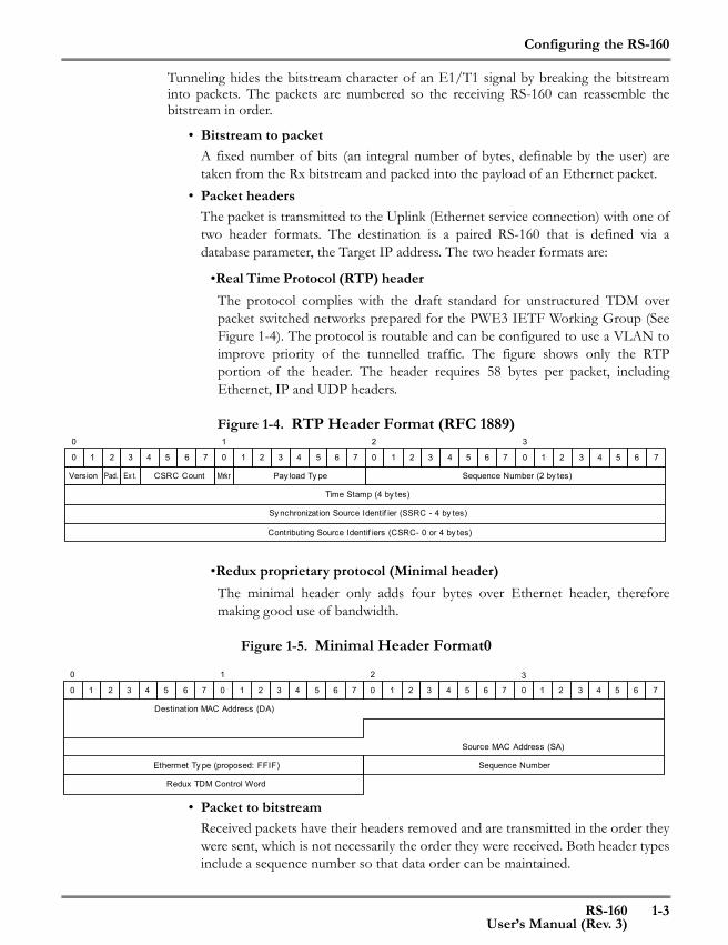
•Real Time Protocol (RTP) header The protocol complies with the draft standard for unstructured TDM overpacket switched networks prepared for the PWE3 IETF Working Group (SeeFigure 1-4). The protocol is routable and can be configured to use a VLAN toimprove priority of the tunnelled traffic. The figure shows only the RTPportion of the header. The header requires 58 bytes per packet, includingEthernet, IP and UDP headers.
Figure 1-4. RTP Header Format (RFC 1889)
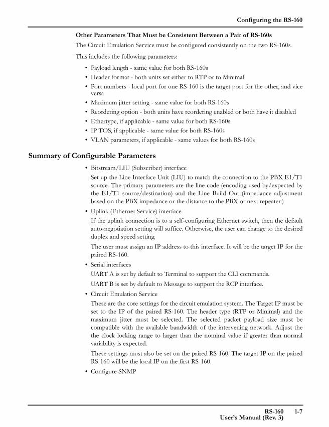
•Redux proprietary protocol (Minimal header)The minimal header only adds four bytes over Ethernet header, thereforemaking good use of bandwidth.
Figure 1-5. Minimal Header Format0
• Packet to bitstreamReceived packets have their headers removed and are transmitted in the order theywere sent, which is not necessarily the order they were received. Both header typesinclude a sequence number so that data order can be maintained.
Version Pad. Ex t. CSRC Count Sequence Number (2 by tes)
Time Stamp (4 by tes)
Sy nchronization Source Identif ier (SSRC - 4 by tes)
Contributing Source Identif iers (CSRC- 0 or 4 by tes)
Mrkr Pay load Ty pe
0 1 2 3 4 5 6 7 0 1 2 3 4 5 6 7 0 1 2 3 4 5 6 7 0 1 2 3 4 5 6 7
0 1 2 3
20 1 3
Destination MAC Address (DA)
Ethermet Ty pe (proposed: FFIF)
Redux TDM Control Word
0 1 2 3 4 5 6 7 0 1 2 3 4 5 6 7 0 1 2 3 4 5 6 7 0 1 2 3 4 5 6 7
Source MAC Address (SA)
Sequence Number

Configuring the RS-160
1-4 RS-160User’s Manual (Rev. 3)
• Jitter buffer/underrun/overrunThe transmitted bitstream must be maintained at a constant rate. Jitter can comefrom two sources: the variability of a packet network, where a packet may not beavailable for transmission, and from small variations in timing between the sourceand destination E1/T1 circuit. The RS-160 maintains a jitter buffer which containsa backlog of packets. The configurable maximum jitter assumes a level of end-to-end network delay. Based on this value, a number of packets received over thenetwork are buffered before the bitstream transmission begins. The number ofpackets in the jitter buffer is calculated based on the maximum jitter inmilliseconds, the packet payload length, and the nominal operating frequency ofthe line format (1.544 MHz for T1 and 2.048 MHz for E1). For example, with apacket payload of 96 bytes on an E1 circuit, one packet is transmitted in 375microseconds. If the maximum jitter is ±10 milliseconds, then the RS-160 willcreate an initial 27-packet backlog.This jitter buffer is monitored continuously. If the incoming data is stable (thenumber of packets in the buffer does not increase or decrease over time), then thedelay is gradually reduced to a minimum level (the latter capability will besupported in a future release).If the buffer empties, this is an underrun condition: the transmitted synchronousbitstream needs to be maintained but there is no data to send. In this case, a fillerpattern is sent until data arrives. The jitter buffer is allowed to build back up to theinitial level to reduce the possibility of future underruns.If the buffer overflows, which is defined as having twice the number of packetswaiting for transmission as the initial backlog, then an overrun condition hasoccurred. Additional received packets are discarded until the jitter buffer dropsback to the initial condition.In normal conditions, the jitter buffer will vary in length by only one or twopackets. Underrun and overrun occurrences indicate that the RS-160 parametersshould be adjusted.To support the clock recovery calculation described below, the application buffersa minimum of five frames. With the 96-byte packet example above, this representsless than 2 milliseconds of delay.
• Replacement framesAnother cause for “underrun” is due to a packet getting delayed or lost in thepacket network. This condition is detected based on the sequence numbers in thepacket headers. If a packet with the right sequence number is not available at theright time, the filler pattern will be sent in its place. If the packet eventually arriveslate, it will be discarded. “Late” in this context means later than twice themaximum jitter setting. This feature is called “packet reordering” and is enabledoptionally.
• Clock recoveryThe RS-160 can recover the transmit clock of data received over the network. Theclock rate is recreated by adaptive clock recovery, and is used to clock out the

Configuring the RS-160
RS-160 1-5User’s Manual (Rev. 3)
bitstream to the receiving end of the circuit. One RS-160 is configured as a Masterthat is driven by the clock detected in the locally received bitstream. The pairedRS-160 is configured as a Slave, which performs the described clock recovery. If acommon stable clock is available at both ends of the link, then both RS-160s canbe configured as Master. The user can select a clock locking range that trades offthe speed of convergence of the derived clock versus the variability of the clockfrom nominal values.
• Jitter buffer length limitationsThe jitter buffer must be at least five packets long. It can be no longer than 64packets when reordering is enabled. Otherwise it can be no longer than 800packets.The jitter buffer length is equal to the maximum jitter setting divided by the packetpayload transmission time:
For example, an E1 payload of 256 bytes will have a transmit time of 1 msec.Similarly, a T1 payload of 192 bytes will have a transmit time of 1 msec. Ifreordering is enabled, then the maximum jitter in both cases is constrained to arange of 5 to 64 msec.
Configuring a Pair of RS-160sRS-160s travel in pairs. They perform point-to-point communications. At startup, eachRS-160 “pings” the other and waits for a response. Pings are retransmitted until eachreceives a response from the other. An RS-160 will start forwarding encapsulatedbitstream data when it has received a response from its pair.
Master versus SlaveClocking is a critical element in a bitstream over packet application. The way that theRS-160 maintains consistent timing is to define one RS-160 as a Master and one as aSlave. Operationally, the Slave uses the clock of the Master as its clock source. As shownin Figure 1-6, the Master uses the clock derived by the Line Interface Unit (LIU) fromthe Rx stream as its Tx clock. The Slave recovers the Master clock from the datareceived over the packet network and uses this value to drive a Baud Rate Generator(BRG). The BRG output is used as the Tx clock of the Slave.
JitterBufLength MaxJitterTransmitTime-------------------------------------=
TransmitTime PayloadLengthDataRate
----------------------------------------=

Configuring the RS-160
1-6 RS-160User’s Manual (Rev. 3)
Both RS-160s can be configured as Master if a common stable clock is available to bothdevices.
The user configures the clocking with the bitstream subscriber clocking parameter. Thisparameter is configurable with the Management Console: See “Transmit clock sourceselect (Recovery (Slave)/Loopback (Master))” on page 2-7.
It is also configurable with the CLI: See “SetConfigBitStream” on page 3-12.
The RPC also supports this function. See “SetConfigBitStream” on page 4-16.
Figure 1-6. An RS-160 Pair
IP AddressesEach RS-160 must be aware of the IP address of the Service (Uplink) port of the otherRS-160. This value is required for maintaining communications between the twodevices.
Enter the local IP address when the Service Interface (Interface C) is defined.
Enter the target IP - the address of the remote RS-160 - when the Circuit EmulationService (CES) is defined.
Slave Clock:Clock recovered from data received from MasterRS-160 and used to drive internal accurate baud rategenerator (BRG). BRG output is input to LIU and toTxclock ("Recovered" Tx clock)Rx clock is locally derived clock.
Master RS-160
Slave RS-160
PacketNetwork
IP Address 1
IP Address2
E1/T1
E1/T1
LIU
Master Clock:Clock derived by LIU from received E1/T1. Used byRS-160 as both RX and Tx clock ("Loopback" Txclock)
Derivedclock
LIU
Recovered clock
IP addresses:Source IP is Subscriber IP: IP address 1Destination IP is CES Destination IP: IP address 2
IP addresses:Source IP is Subscriber IP: IP address 2Destination IP is CES Destination IP: IP address 1
RXC, TXC
PLL
BRG TXC
RXC Derivedclock
Configuring the RS-160
RS-160 1-7User’s Manual (Rev. 3)
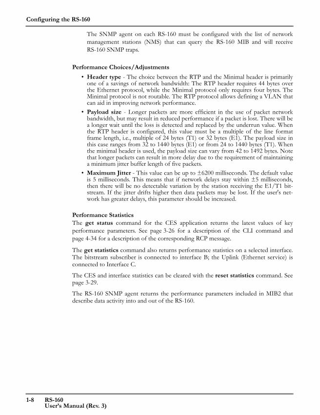
Other Parameters That Must be Consistent Between a Pair of RS-160sThe Circuit Emulation Service must be configured consistently on the two RS-160s.
This includes the following parameters:
• Payload length - same value for both RS-160s• Header format - both units set either to RTP or to Minimal• Port numbers - local port for one RS-160 is the target port for the other, and vice
versa• Maximum jitter setting - same value for both RS-160s• Reordering option - both units have reordering enabled or both have it disabled• Ethertype, if applicable - same value for both RS-160s• IP TOS, if applicable - same value for both RS-160s• VLAN parameters, if applicable - same values for both RS-160s
Summary of Configurable Parameters• Bitstream/LIU (Subscriber) interface
Set up the Line Interface Unit (LIU) to match the connection to the PBX E1/T1source. The primary parameters are the line code (encoding used by/expected bythe E1/T1 source/destination) and the Line Build Out (impedance adjustmentbased on the PBX impedance or the distance to the PBX or next repeater.)
• Uplink (Ethernet Service) interfaceIf the uplink connection is to a self-configuring Ethernet switch, then the defaultauto-negotiation setting will suffice. Otherwise, the user can change to the desiredduplex and speed setting.The user must assign an IP address to this interface. It will be the target IP for thepaired RS-160.
• Serial interfacesUART A is set by default to Terminal to support the CLI commands.UART B is set by default to Message to support the RCP interface.
• Circuit Emulation ServiceThese are the core settings for the circuit emulation system. The Target IP must beset to the IP of the paired RS-160. The header type (RTP or Minimal) and themaximum jitter must be selected. The selected packet payload size must becompatible with the available bandwidth of the intervening network. Adjust thethe clock locking range to larger than the nominal value if greater than normalvariability is expected.These settings must also be set on the paired RS-160. The target IP on the pairedRS-160 will be the local IP on the first RS-160.
• Configure SNMP
Configuring the RS-160
1-8 RS-160User’s Manual (Rev. 3)
The SNMP agent on each RS-160 must be configured with the list of networkmanagement stations (NMS) that can query the RS-160 MIB and will receiveRS-160 SNMP traps.
Performance Choices/Adjustments• Header type - The choice between the RTP and the Minimal header is primarily
one of a savings of network bandwidth: The RTP header requires 44 bytes overthe Ethernet protocol, while the Minimal protocol only requires four bytes. TheMinimal protocol is not routable. The RTP protocol allows defining a VLAN thatcan aid in improving network performance.
• Payload size - Longer packets are more efficient in the use of packet networkbandwidth, but may result in reduced performance if a packet is lost. There will bea longer wait until the loss is detected and replaced by the underrun value. Whenthe RTP header is configured, this value must be a multiple of the line formatframe length, i.e., multiple of 24 bytes (T1) or 32 bytes (E1). The payload size inthis case ranges from 32 to 1440 bytes (E1) or from 24 to 1440 bytes (T1). Whenthe minimal header is used, the payload size can vary from 42 to 1492 bytes. Notethat longer packets can result in more delay due to the requirement of maintaininga minimum jitter buffer length of five packets.
• Maximum Jitter - This value can be up to ±6200 milliseconds. The default valueis 5 milliseconds. This means that if network delays stay within ±5 milliseconds,then there will be no detectable variation by the station receiving the E1/T1 bit-stream. If the jitter drifts higher then data packets may be lost. If the user's net-work has greater delays, this parameter should be increased.
Performance StatisticsThe get status command for the CES application returns the latest values of keyperformance parameters. See page 3-26 for a description of the CLI command andpage 4-34 for a description of the corresponding RCP message.
The get statistics command also returns performance statistics on a selected interface.The bitstream subscriber is connected to interface B; the Uplink (Ethernet service) isconnected to Interface C.
The CES and interface statistics can be cleared with the reset statistics command. Seepage 3-29.
The RS-160 SNMP agent returns the performance parameters included in MIB2 thatdescribe data activity into and out of the RS-160.

2
This chapter gives a quick configuration method for the IPM-1SE. The following is broken into 5 steps that need to be configured for each unit. For clocking concerns, the IPM-1SE pair can be considered transparent. However, for proper operation, the configuration must be set to place the "Master" unit towards the E1 clock source (towards the up stream) and place the "Slave" unit towards the CPE side. Connect the IPM-1SE via serial console cable to a PC or notebook with HyperTerminal program or other VT-100 compatible terminal program and set the communication parameters for 115.2k, 8 bits, no parity, 1 stop bit, and no flow control. Once the terminal is connected to the IPM, power on the IPM and the terminal show display the IPM's prompt. Comments are placed in brackets { }. RS160:\> Configuration Steps for Master unit. Step 1. dBase initialize RS160:\> a {enter the admin menu} RS160:\Admin> sddb e1 loopback {call up initial database} RS160:\Admin> \c\rr {Replace & Reload} Step 2. Uplink's TCP/IP setting RS160:\> c {enter configuration menu} RS160:\Config> up {enter Uplink menu} RS160:\Config\UPLINK> ssip 10.128.46.18 {Set Static IP} RS160:\Config\UPLINK> ssnm 255.255.254.0 {Set SubNet Mask} RS160:\Config\UPLINK> \c\rr {Replace & Reload} Step 3. Uplink's default gateway RS160:\> c {enter configuration menu} RS160:\Config> g {enter general menu} RS160:\Config\General> sdg 10.128.46.1 {Set Default Gateway} RS160:\Config\General> \c\rr {Replace & Reload} Step 4. Configure E1 RS160:\> c {enter configuration menu} RS160:\Config> e1 {enter E1 menu} RS160:\Config\E1> sccm loopback {set config clocking mode master} RS160:\Config\E1> sfm framed {set frame mode framed} RS160:\Config\E1> sllc hdb3 {set LUI line code HDB3} RS160:\Config\E1> sltt e1_120 {set LUI buildout E1} RS160:\Config\E1> slrt 120ohm {set LUI Rx termination 120 Ohms} RS160:\Config\E1> sfp pcm31 {set frame parameter PCM31} RS160:\Config\E1> \c\rr {Replace & Reload}
Quick Configure
RS-160 2-1 User's Manual (REV. 3)
Quick Configure
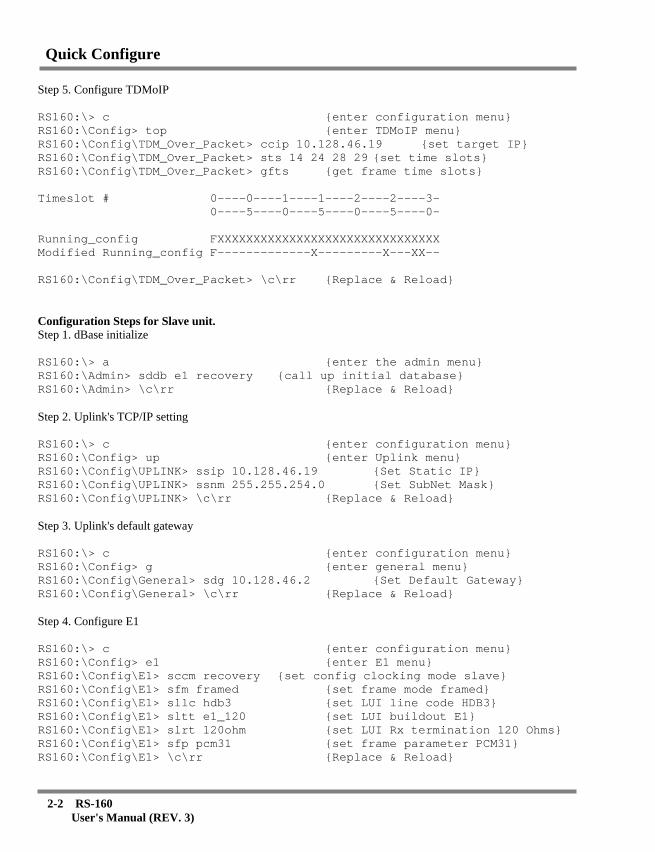
Step 5. Configure TDMoIP RS160:\> c {enter configuration menu} RS160:\Config> top {enter TDMoIP menu} RS160:\Config\TDM_Over_Packet> ccip 10.128.46.19 {set target IP} RS160:\Config\TDM_Over_Packet> sts 14 24 28 29 {set time slots} RS160:\Config\TDM_Over_Packet> gfts {get frame time slots} Timeslot # 0----0----1----1----2----2----3- 0----5----0----5----0----5----0- Running_config FXXXXXXXXXXXXXXXXXXXXXXXXXXXXXXX Modified Running_config F-------------X---------X---XX-- RS160:\Config\TDM_Over_Packet> \c\rr {Replace & Reload} Configuration Steps for Slave unit. Step 1. dBase initialize RS160:\> a {enter the admin menu} RS160:\Admin> sddb e1 recovery {call up initial database} RS160:\Admin> \c\rr {Replace & Reload} Step 2. Uplink's TCP/IP setting RS160:\> c {enter configuration menu} RS160:\Config> up {enter Uplink menu} RS160:\Config\UPLINK> ssip 10.128.46.19 {Set Static IP} RS160:\Config\UPLINK> ssnm 255.255.254.0 {Set SubNet Mask} RS160:\Config\UPLINK> \c\rr {Replace & Reload} Step 3. Uplink's default gateway RS160:\> c {enter configuration menu} RS160:\Config> g {enter general menu} RS160:\Config\General> sdg 10.128.46.2 {Set Default Gateway} RS160:\Config\General> \c\rr {Replace & Reload} Step 4. Configure E1 RS160:\> c {enter configuration menu} RS160:\Config> e1 {enter E1 menu} RS160:\Config\E1> sccm recovery {set config clocking mode slave} RS160:\Config\E1> sfm framed {set frame mode framed} RS160:\Config\E1> sllc hdb3 {set LUI line code HDB3} RS160:\Config\E1> sltt e1_120 {set LUI buildout E1} RS160:\Config\E1> slrt 120ohm {set LUI Rx termination 120 Ohms} RS160:\Config\E1> sfp pcm31 {set frame parameter PCM31} RS160:\Config\E1> \c\rr {Replace & Reload}
2-2 RS-160 User's Manual (REV. 3)

Quick Configure
Step 5. Configure TDMoIP RS160:\> c {enter configuration menu} RS160:\Config> top {enter TDMoIP menu} RS160:\Config\TDM_Over_Packet> ccip 10.128.46.18 {set target IP} RS160:\Config\TDM_Over_Packet> sts 14 24 28 29 {set time slots} RS160:\Config\TDM_Over_Packet> gfts {get frame time slots} Timeslot # 0----0----1----1----2----2----3- 0----5----0----5----0----5----0- Running_config FXXXXXXXXXXXXXXXXXXXXXXXXXXXXXXX Modified Running_config F-------------X---------X---XX-- RS160:\Config\TDM_Over_Packet> \c\rr {Replace & Reload} The previous TDM configuration is for E1, 120 ohm connection to the RJ-45 connectors. To connect via twisted pair on the RJ-45 TDM connector, the connections are: 1 - RRING 2 - RTIP 4 - TRING 5 - TTIP No configuration was done for the local LAN port. Connect the IP network to the Uplink connector, straight UTP will connect to switch.
Fine tuning There are two parameters that should be adjusted to provide error free operation in "real" networks; they are the jitter buffer and the payload length. Jitter Buffer: The default jitter buffer for a full E1 unframed transmission is only 5ms. If the latency of Ethernet on the master to slave units is more than 5ms, errors will occur. To check LAN latency, issue a ping from the LAN A to LAN B. Find the average latency and increase the jitter buffer to handle the latency. For voice applications, keep the jitter buffer under 250ms (1/4 second) to avoid any noticeable delay in voice. The command to modify the jitter buffer is: RS160:\> c {enter configuration menu} RS160:\Config> top {enter TDMoIP menu} RS160:\Config\TDM_Over_Packet> cclk 100 {increase jitter to 100ms} RS160:\Config\TDM_Over_Packet> \c\rr {save} Payload Length: In wireless applications, a large payload is preferred. In unframed E1, the default payload length is only 96bytes. To increase it do the following: RS160:\> c {enter configuration menu} RS160:\Config> top {enter TDMoIP menu} RS160:\Config\TDM_Over_Packet> ccpl 265 {set payload to 256 bytes} RS160:\Config\TDM_Over_Packet> \c\rr {save}
RS-160 2-3 User's Manual (REV. 3)

Quick Configure
2-4 RS-160 User's Manual (REV. 3)

RS-160 3-1User’s Manual (Rev. 3)
3 CLI Commands3
This chapter describes the command line interface (CLI) commands used to configurethe RS-160 and to display the configuration and status of the device.
Configuring the RS-160The RS-160 has an internal, non-volatiledatabase that is activated when the device ispowered up or restarted. The is database iscalled the Startup Config. At power on, theStartup config is copied to two locations: therunning-config and the modified running-config.
The database contains all the informationnecessary to configure the RS-160 for anapplication. The initial values of the databaseare the default conditions of the device.
CLI commands are used to change theconfiguration parameters to adapt to a specificapplication of the RS-160. Most parameterchanges are made to the modified running-config.
Once the modified running-configuration hasbeen validated, copy it to the Startup configusing the “replace” (rp) command.
Use the “reload” (rl) command to restart theRS-160 with the Startup config.
The “ReplaceReload” (rr) command copies themodified running-config to the Startup configand reloads with a single command.
Startup config
modifiedrunning-config
running-config
Startup config
modifiedrunning-config
running-config
CLI Commands
Startup config
modifiedrunning-config
running-config
Replace
Reload

CLI Commands
3-2 RS-160User’s Manual (Rev. 3)
The GetConfiguration (gc) command, used to display configuration information invarious contexts, displays two sets of values: the parameters in the running-config andthe corresponding values in the modified running-config.
How to Access the CLI
Connecting via the CONSOLE portThe CONSOLE is configured for the following parameters:
• Baud Rate: 115200 • Data Bit: 8• Stop Bit: 1• Parity: None• Flow Control: None
Connect to the CONSOLE using a serial connection and a “dumb” terminal or acharacter terminal emulator such as Hyper terminal or a PC command window. Pressreturn and the RS-160 will respond with the command prompt: (CM160:\>).
Connecting via Telnet and a network interfaceThe LAN port is configured with an IP address of 192.160.16.1, and the UPLINK portis configured either with an IP address of 169.254.1.5 (Master) or 169.254.1.6 (Slave).Both ports are configured with a subnet mask of 255.255.0.0. The user can connect viaTelnet to the defined IP address using HyperTerminal or a command window on a PCor any other Telnet client. Once the connection is made, the RS-160 will respond withthe command prompt (CM160:\>).
If the IP address needs to be changed to another value before making a networkconnection, first connect via the CONSOLE and change the LAN or UPLINK IPaddress and subnet mask using the following two commands:
• SetStaticIP (ssip) (see page 3-31)• SetSubNetMask (ssnm) (see page 3-32)
CLI Command Description ConventionsThe command descriptions in this document follow the following conventions:
• Command names and their abbreviations are shown in bold font.• Command arguments are shown in angle brackets (< >).• Required alternative keywords are grouped in braces and separated by vertical bars
({A|B|C})• Elements in square brackets ([ ]) are optional.• Screen fonts are used in examples of user entry and resulting output. User
entry examples are in bold screen font.

CLI Commands
RS-160 3-3User’s Manual (Rev. 3)
If the user enters a command preceded by a question mark (?) and a blank, help isdisplayed, providing immediate help formatting commands, as shown in the followingexample:
CM160:\Config\TDM_Over_Packet>? ccap
Configures CES header protocol.
Parameters: <protocol: {RTP|Minimal}>
Optional Parameters:
[<ethertype(Hex)>
<local-port>
<target-port>]
Typing a ? after entering a command and one or more parameters results in a validationof the parameters and a display of the command help text. The command as entered isre-displayed. This capability is useful when the user has forgotten the sequence ofparameters while in the middle of entering a command.
The CLI command parser evaluates each parameter and generates an error on the firsterror found, for example, entering ccap q (the first parameter must be “RTP” or“minimal”) results in a parser error:
Error, Parameter 1, wrong value (keyword)
The following message is returned if the entered parameters are parsed correctly:The request was updated successfully in modifiedrunning_config.
The configuration change will be activated after thenext Replace&Reload (\c\rr)
If the command entered changes a dynamic parameter - one that is not recorded in thedatabase - for example, a loopback command, the following message is returned:
The command completed successfully.
If the entered parameters parse correctly but not all required parameters are entered orthe entered values are an incorrect combination for the selected command, the followingmessage is sent:
Modified-running-config was not updated or accessedwith this request.
See the description of SetConfigCESProtocol on page 3-39 for an example of how thevalue of one parameter can constrain the value of other parameters.
CLI Command HierarchyThe CLI commands are organized in a hierarchal directory structure as shown inFigure 3-1. Each directory has subdirectories and/or commands within it.
The following commands are used to navigate the command directories:
• dir - lists the commands and sub-directories in the current directory
CLI Commands
3-4 RS-160User’s Manual (Rev. 3)
• up arrow and down arrow - display previously entered commands (up to the last12)
• Entering a sub-directory name or its abbreviation transfers control to that direc-tory. One can move down the hierarchy by more than one level by entering thedesired sub-directory path, with “\” separating the directory names, for exampleCM160:\>m\lan
CM160:\Monitor\LAN>
• Starting with “\” allows entering the path to a directory starting from the rootdirectory, for example:CM160:\Monitor\LAN>\c\lan
CM160:\Config\LAN>
• If the full path to a directory is entered followed by a command, the default direc-tory when the command was entered will remain the same., for example:CM160:\Monitor\LAN>\c\lan
CM160:\Config\LAN>
• Entering “..” moves up the directory hierarchy one level. This can be repeated(..\..) or combined with directory names to move up and down the hierarchy,for example\Monitor\UPLINK>..\..\a\top
\Monitor\TDM_Over_Packet>

CLI Commands
RS-160 3-5User’s Manual (Rev. 3)
Figure 3-1. Command Directory Hierarchy
Certain commands with the same name appear in more than one sub-directory. Thecommand functions differently depending on the context, for example, the GetConfig(gc) command displays different results depending on the interface or applicationdirectory where it is executed.
Root directory \>
Config(C)
Monitor(M)
Diagnostics(D)
Admin(A)
Debug (D)
TDM_Over_Packet(TOP)
SNMP (S)
LAN
UPLINK (UP)
E1, T1 or J1
CONSOLE (CONS)
Bridging_Services(BRS)
General (G)
TDM_Over_Packet(TOP)
SNMP (S)
LAN
UPLINK (UP)
E1, T1 or J1
CONSOLE (CONS)
Bridging_Services(BRS)
General (G)
CLI Commands
3-6 RS-160User’s Manual (Rev. 3)
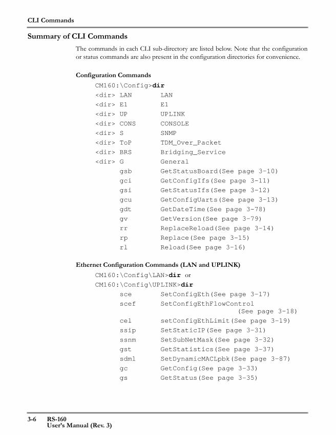
Summary of CLI CommandsThe commands in each CLI sub-directory are listed below. Note that the configurationor status commands are also present in the configuration directories for convenience.
Configuration CommandsCM160:\Config>dir
<dir> LAN LAN
<dir> E1 E1
<dir> UP UPLINK
<dir> CONS CONSOLE
<dir> S SNMP
<dir> ToP TDM_Over_Packet
<dir> BRS Bridging_Service
<dir> G General
gsb GetStatusBoard(See page 3-10)
gci GetConfigIfs(See page 3-11)
gsi GetStatusIfs(See page 3-12)
gcu GetConfigUarts(See page 3-13)
gdt GetDateTime(See page 3-78)
gv GetVersion(See page 3-79)
rr ReplaceReload(See page 3-14)
rp Replace(See page 3-15)
rl Reload(See page 3-16)
Ethernet Configuration Commands (LAN and UPLINK)CM160:\Config\LAN>dir orCM160:\Config\UPLINK>dir
sce SetConfigEth(See page 3-17)
scef SetConfigEthFlowControl(See page 3-18)
cel setConfigEthLimit(See page 3-19)
ssip SetStaticIP(See page 3-31)
ssnm SetSubNetMask(See page 3-32)
gst GetStatistics(See page 3-37)
sdml SetDynamicMACLpbk(See page 3-87)
gc GetConfig(See page 3-33)
gs GetStatus(See page 3-35)

CLI Commands
RS-160 3-7User’s Manual (Rev. 3)
E1/T1 Configuration CommandsCM160:\Config\E1>dir orCM160:\Config\T1>dir
sccm SetConfigBitstreamClockingMode(See page 3-20)
sbuv SetConfigBitStreamUnderVal(See page 3-21)
sfm SetFrameMode(See page 3-22)
sbdl SetBitstreamDynamicLpbk(See page 3-88)
gst GetStatistics(See page 3-37)
gc GetConfig(See page 3-33)
gs GetStatus(See page 3-33)
sllc SetConfigLIULineCode(See page 3-23)
sltt SetConfigLIULineBuildout(See page 3-26)
slrt SetConfigLIURxTerm(See page 3-27)
sljt SetConfigJitterAttenuation(See page 3-28)
slrg SetConfigMonitorGain(See page 3-29)
sreg SetRxEqualizerGainLimit(See page 3-30)
sldl SetLIUDynamicLpbk(See page 3-89)
gfts GetFrameTimeSlots(See page 3-23)
sfp SetFramedParams(See page 3-24)
CONSOLE Configuration CommandsCM160:\Config\CONSOLE>dir
scu SetConfigUART(See page 3-38)
gc GetConfig(See page 3-33)
SNMP Configuration CommandsCM160:\Config\SNMP>dir
arm AddRequestManager(See page 3-59)
rrm RemoveRequestManager(See page 3-60)
grm GetRequestManagers(See page 3-61)
atm AddTrapManager(See page 3-62)
rtm RemoveTrapManager(See page 3-63)
gtm GetTrapManagers(See page 3-64)
srp SetRequestPort(See page 3-65)

CLI Commands
3-8 RS-160User’s Manual (Rev. 3)
stp SetTrapPort(See page 3-67)
gp GetRequestTrapPorts(See page 3-66)
TDM over Packet Configuration CommandsCM160:\Config\TDM_Over_Packet>dir
ccap SetConfigCESProtocol(See page 3-39)
ccip SetConfigCESIP(See page 3-41)
ccpl SetConfigCESPayLength(See page 3-42)
cclk SetConfigCESClock(See page 3-43)
ccvl SetConfigCESVlan(See page 3-44)
scr SetCESreOrder(See page 3-45)
cclr SetConfigCESClockRange(See page 3-46)
gfts GetFrameTimeSlots(See page 3-23)
sts SetTimeSlots(See page 3-47)
ats AddTimeSlots(See page 3-48)
rts RemoveTimeSlots(See page 3-49)
sfp SetFramedParams(See page 3-24)
sctm SetCESappTestMode(See page 3-50)
gc GetConfig(See page 3-33)
gs GetStatus(See page 3-35)
Bridging Service CommandsCM160:\Config\Bridging_Service>dir
sb SetBridging(See page 3-52)
sat SetAgingTime(See page 3-53)
cb ClearBridging(See page 3-54)
gc GetConfig(See page 3-33)
gs GetStatus(See page 3-35)
General Configuration CommandsCM160:\Config\General>dir
sdg SetDefGateway(See page 3-55)
gdg GetDefGateway(See page 3-56)
gma GetMACAddress(See page 3-58)
CLI Commands
RS-160 3-9User’s Manual (Rev. 3)
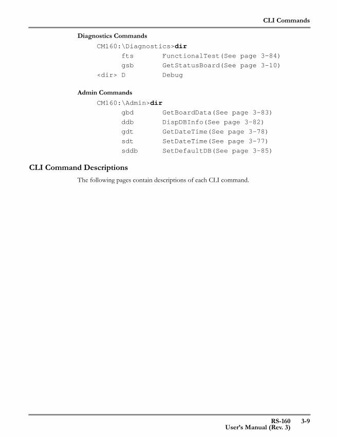
Diagnostics CommandsCM160:\Diagnostics>dir
fts FunctionalTest(See page 3-84)
gsb GetStatusBoard(See page 3-10)
<dir> D Debug
Admin CommandsCM160:\Admin>dir
gbd GetBoardData(See page 3-83)
ddb DispDBInfo(See page 3-82)
gdt GetDateTime(See page 3-78)
sdt SetDateTime(See page 3-77)
sddb SetDefaultDB(See page 3-85)
CLI Command DescriptionsThe following pages contain descriptions of each CLI command.
CLI Commands
3-10 RS-160User’s Manual (Rev. 3)
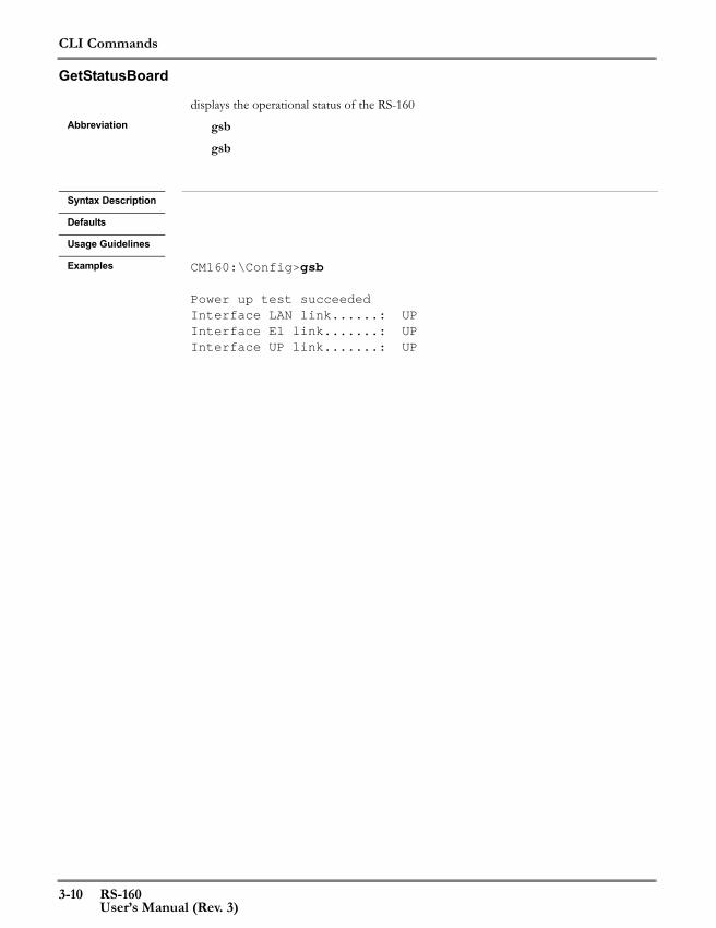
GetStatusBoard
displays the operational status of the RS-160Abbreviation gsb
gsb
Syntax Description
Defaults
Usage Guidelines
Examples CM160:\Config>gsb
Power up test succeededInterface LAN link......: UPInterface E1 link.......: UPInterface UP link.......: UP
CLI Commands
RS-160 3-11User’s Manual (Rev. 3)
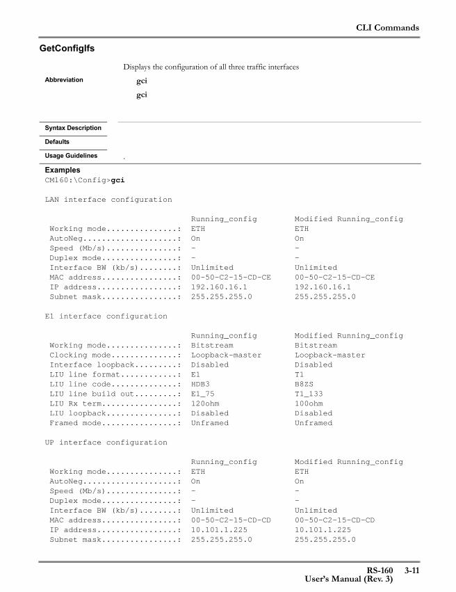
GetConfigIfs
Displays the configuration of all three traffic interfaces Abbreviation gci
gci
Syntax Description
Defaults
Usage Guidelines .
ExamplesCM160:\Config>gci
LAN interface configuration
Running_config Modified Running_config Working mode...............: ETH ETH AutoNeg....................: On On Speed (Mb/s)...............: - - Duplex mode................: - - Interface BW (kb/s)........: Unlimited Unlimited MAC address................: 00-50-C2-15-CD-CE 00-50-C2-15-CD-CE IP address.................: 192.160.16.1 192.160.16.1 Subnet mask................: 255.255.255.0 255.255.255.0
E1 interface configuration
Running_config Modified Running_config Working mode...............: Bitstream Bitstream Clocking mode..............: Loopback-master Loopback-master Interface loopback.........: Disabled Disabled LIU line format............: E1 T1 LIU line code..............: HDB3 B8ZS LIU line build out.........: E1_75 T1_133 LIU Rx term................: 120ohm 100ohm LIU loopback...............: Disabled Disabled Framed mode................: Unframed Unframed
UP interface configuration
Running_config Modified Running_config Working mode...............: ETH ETH AutoNeg....................: On On Speed (Mb/s)...............: - - Duplex mode................: - - Interface BW (kb/s)........: Unlimited Unlimited MAC address................: 00-50-C2-15-CD-CD 00-50-C2-15-CD-CD IP address.................: 10.101.1.225 10.101.1.225 Subnet mask................: 255.255.255.0 255.255.255.0
CLI Commands
3-12 RS-160User’s Manual (Rev. 3)
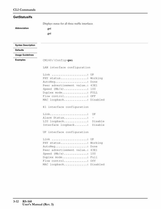
GetStatusIfs
Displays status for all three traffic interfacesAbbreviation gsi
gsi
Syntax Description
Defaults
Usage Guidelines
Examples CM160:\Config>gsi
LAN interface configuration
Link ....................: UPPHY status...............: WorkingAutoNeg..................: DonePeer advertisement value.: 43E1Speed (Mb/s).............: 100Duplex mode..............: FULLFlow control.............: OFFMAC loopback.............: Disabled
E1 interface configuration
Link.....................: UPAlarm Status.............: -LIU loopback.............: DisableInterface loopback.......: Disable
UP interface configuration
Link ....................: UPPHY status...............: WorkingAutoNeg..................: DonePeer advertisement value.: 43E1Speed (Mb/s).............: 100Duplex mode..............: FullFlow control.............: OffMAC loopback.............: Disabled

CLI Commands
RS-160 3-13User’s Manual (Rev. 3)
GetConfigUarts
Returns the CONSOLE configurationAbbreviation gcu
gcu
Syntax Description
Defaults
Usage Guidelines
Examples CM160:\Config>gcu
CONS configuration
Running_config Modified Running_config
Baud rate..........: 115200 115200 Stop bit...........: 1 1 Protocol...........: Term Term Mode...............: Enabled Enabled

CLI Commands
3-14 RS-160User’s Manual (Rev. 3)
ReplaceReload
Replaces the restart configuration with the modified running configuration and then restarts the RS-160
Abbreviation rrrr
Syntax Description
Defaults
Usage Guidelines This command is used to capture the modified running configuration permanently. The modified running-config contains all parameter changes made since the last restart
Examples CM160:\Config\>rr
Startup-config-DB replaced
Restarting from startup-config-DBCM160 R01.01.02_D002-200

CLI Commands
RS-160 3-15User’s Manual (Rev. 3)
Replace
Replaces the restart configuration with the modified running configurationAbbreviation rp
rp
Syntax Description
Defaults
Usage Guidelines This command is used to capture the modified running configuration permanently. The modified running-config contains all parameter changes made since the last restart
Examples CM160:\Config\>rp
Startup-config-DB replaced

CLI Commands
3-16 RS-160User’s Manual (Rev. 3)
Reload
Restarts the RS-160 using the startup configurationAbbreviation rl
rl
Syntax Description
Defaults
Usage Guidelines If any configuration changes were made to the modified running-config, they will be lost unless a Replace (rp) command was executed firs. Use the rr command to perform both operations in a single step.
Examples CM160:\Config>rl
Restarting from startup-config-DBCM160 R01.01.02_D002-200
CLI Commands
RS-160 3-17User’s Manual (Rev. 3)
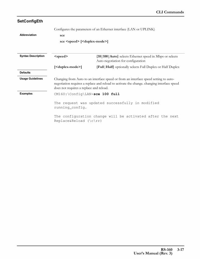
SetConfigEth
Configures the parameters of an Ethernet interface (LAN or UPLINK)Abbreviation sce
sce <speed> [<duplex-mode>]
Syntax Description <speed> {10|100|Auto} selects Ethernet speed in Mbps or selects
Auto negotiation for configuration
[<duplex-mode>] {Full|Half} optionally selects Full Duplex or Half DuplexDefaults
Usage Guidelines Changing from Auto to an interface speed or from an interface speed setting to auto-negotiation requires a replace and reload to activate the change. changing interface speed does not requires a replace and reload.
Examples CM160:\Config\LAN>sce 100 full
The request was updated successfully in modified running_config.
The configuration change will be activated after the next Replace&Reload (\c\rr)
CLI Commands
3-18 RS-160User’s Manual (Rev. 3)
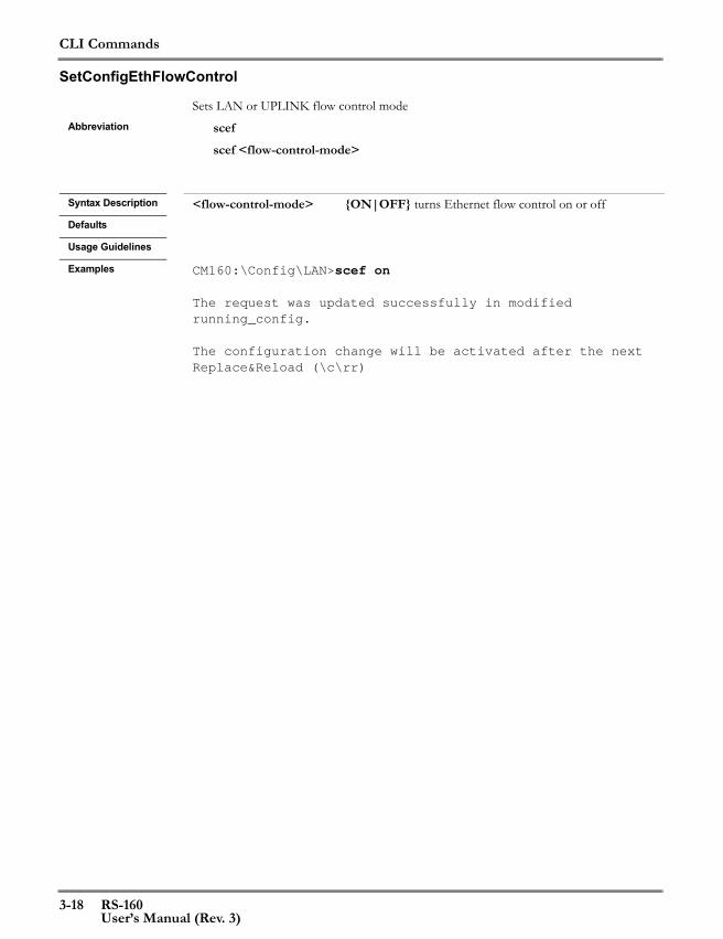
SetConfigEthFlowControl
Sets LAN or UPLINK flow control modeAbbreviation scef
scef <flow-control-mode>
Syntax Description <flow-control-mode> {ON|OFF} turns Ethernet flow control on or off Defaults
Usage Guidelines
Examples CM160:\Config\LAN>scef on
The request was updated successfully in modified running_config.
The configuration change will be activated after the next Replace&Reload (\c\rr)
CLI Commands
RS-160 3-19User’s Manual (Rev. 3)
SetConfigEthLimit
Defines a bandwidth limitation for either the LAN or UPLINK interface.Abbreviation cel
cel <BW-limit-in-kbits>
Syntax Description <BW-limit-in-kbits > 1-100000 (0 indicates no limitation on this interface)Defaults
Usage Guidelines This value limits the bandwidth of traffic transmitted from the selected interface. The value on the UPLINK interface includes packetized E1/T1 traffic. The user must evaluate two values to determine this setting:1. The amount of bandwidth used by the packetized E1/T1. Enter \c\top\gs to see the amount of bandwidth used.2. The maximum bandwidth of the slowest link between one RS-160 and its peer.If the bandwidth required is larger than the slowest link, reduce the packetized E1/T1 bandwidth by increasing the size of the packet payload. This reduces the number of packet headers and therefore the amount of required bandwidth.Set the UPLINK bandwidth to the bandwidth of the slowest link.If the interface is configured for 10Mbps, then the maximum permitted value is 10000.The difference between the E1/T1 bandwidth and the set maximum bandwidth is available for packet traffice between the LAN and UPLINK interfaces.
Examples In this example, packetized E1 requires 3.284 Mbps. The slowest link is 4Mbps. CM160:\Config\UPLINK>cel 4000
The request was updated successfully in modified running_config.
The configuration change will be activated after the next Replace&Reload (\c\rr)

CLI Commands
3-20 RS-160User’s Manual (Rev. 3)
SetConfigBitStreamClockingMode
Sets the bitstream clocking mode for the E1/T1 interface. This setting determines whether the RS-160 is operating as a Master or as a Slave.
Abbreviation sccmsccm <clocking-mode>
Syntax Description <clocking-mode> {RECOVERY|LOOPBACK} “Recovery” uses the fine
baud rate generator (BRG) clock calculated from received bitstream packets as the Tx clock (the other RS-160 is the Master).“Loopback” uses the local LIU clock, which is based on its E1 or T1 connection, as the Tx clock (this RS-160 is the Master).
Defaults
Usage Guidelines
Examples CM160:\Config\E1>sccs loopbackThe request was updated successfully in modified running_config.
The configuration change will be activated after the next Replace&Reload (\c\rr)

CLI Commands
RS-160 3-21User’s Manual (Rev. 3)
SetConfigBitStreamUnderVal
Sets the Bit Stream underrun byte value configuration Abbreviation sbuv
sbuv <underrun_value>
Syntax Description <underrun_value> underrun byte value (0x1 to 0xFF) When a bitstream
packet arrives late or is lost, or no data is received, filler bytes are transmitted with this underrun value
Defaults
Usage Guidelines
Examples CM160:\Config\E1>sbuv 0x98The request was updated successfully in modified running_config.
The configuration change will be activated after the next Replace&Reload (\c\rr)

CLI Commands
3-22 RS-160User’s Manual (Rev. 3)
SetFrameMode
Selects the frame mode of operationAbbreviation sfm
sfm <frame_mode>
Syntax Description <frame_mode> {Full|Framed|Unframed}
Full: Complete E1/T1 frames will be detected and forwardedFramed: Selected timeslots from E1/T1 frames will be for-wardedUnframed: Bytes from the incoming bitstream will be grouped into a packet and forwarded, without synchronizing to the incoming frames.
Defaults
Usage Guidelines
Examples CM160:\Config\E1>sfm framedThe request was updated successfully in modified running_config.
The configuration change will be activated after the next Replace&Reload (\c\rr)
CLI Commands
RS-160 3-23User’s Manual (Rev. 3)
GetFrameTimeSlots
Displays the selected time slots that will be forwardedAbbreviation gfts
gfts
Syntax Description
Defaults
Usage Guidelines The display varies depending on whether the RS-160 is operating in T1 or E1. The legend below explains the symbols used in the display.
Examples The example below shows the selected time slot display for T1. The running-config is set for unframed, and the modified running-config is set to full.CM160:\Config\TDM_Over_Packet>gftsCM160:\Config\E1>gftsTimeSlot# 00---0----1----1----2---- 01---5----0----5----0----
Running_config -------------------------Modified Running_config fXXXXXXXXXXXXXXXXXXXXXXXX
X : Selected- : Not selected* : Not applicableF : framing information in-bandf : framing information out-of-bandS : signaling information in-bands : signaling information out-of-band

CLI Commands
3-24 RS-160User’s Manual (Rev. 3)
SetFramedParams
Defines framing parameters used to configure the internal framer.Abbreviation sfp
sfp <frame_format>
Syntax Description <frame_format> E1: {PCM30|PCM31}
T1: {ESF|D4} Defaults
Usage Guidelines The framing option selected is used by the internal framer to synchronize with the E1/T1 source.
Examples CM160:\Config\E1>sfp PCM31The request was updated successfully in modified running_config.
The configuration change will be activated after the next Replace&Reload (\c\rr)
CLI Commands
RS-160 3-25User’s Manual (Rev. 3)
SetConfigLIULineCode
Sets the LIU line codingAbbreviation sllc
sllc <line_code>
Syntax Description <line_code> {AMI|HDB3|B8ZS} HDB3 is used for E1; B8ZS is used
for T1 and J1; AMI is used for both E1 and T1Defaults
Usage Guidelines The value used depends on the settings of the E1/T1/J1 sourceExamples CM160:\Config\E1>sllc ami
The request was updated successfully in modified running_config.
The configuration change will be activated after the next Replace&Reload (\c\rr)

CLI Commands
3-26 RS-160User’s Manual (Rev. 3)
SetConfigLIUlineBuildout
Configures LIU line build outAbbreviation sltt
sltt <line_build_out>
Syntax Description <line_build_out> E1 options:
{E1_75|E1_120|E1_75_HRL|E1_120_HRL}T1/J1 options: {T1_133|T1_266|T1_399|T1_533|T1_655|T1_7.5|T1_15|T1_22.5}Select this parameter as a function of the impedance or length of the connection to the E1/T1 source.
Defaults
Usage Guidelines
Examples CM160:\Config\E1>sltt e1_75The request was updated successfully in modified running_config.
The configuration change will be activated after the next Replace&Reload (c\rr)
CLI Commands
RS-160 3-27User’s Manual (Rev. 3)
SetConfigLIURxTerm
Sets the LIU line Rx terminationAbbreviation slrt
slrt <line_Rx_termination>
Syntax Description <line_Rx_termination> {TermDis|75ohm|100ohm|120ohm|110ohm} “Term-
Dis” indicates that the internal Rx termination is disabled. Valid values for different line formats:E1: 75 Ohm and 120 OhmT1: 100 OhmJ1: 110 Ohm (supported in future release)See the LIU data sheet for more information about this parameter.
Defaults
Usage Guidelines
Examples CM160:\Config\E1>slrt 120ohmThe request was updated successfully in modified running_config.
The configuration change will be activated after the next Replace&Reload (c\rr)

CLI Commands
3-28 RS-160User’s Manual (Rev. 3)
SetConfigJitterAttenuation
Enables/disables the LIU internal Tx jitter attenuatorAbbreviation sljt
sljt <jitter_atten_activation>
Syntax Description <jitter_atten_activation> {Enable|Disable}Defaults
Usage Guidelines Enabling this parameter adds a 128-bit FIFO to the Tx path. Examples CM160:\Config\E1>sljt enable
The request was updated successfully in modified running_config.
The configuration change will be activated after the next Replace&Reload (\c\rr)

CLI Commands
RS-160 3-29User’s Manual (Rev. 3)
SetConfigMonitorGain
Sets the Rx monitor gain for an LIUAbbreviation slrg
slrg <monitor_gain>
Syntax Description <monitor_gain> {Norm|20db|26db|32db}Defaults
Usage Guidelines This parameter is usually left at “Norm”.Examples CM160:\Config\E1>slrg norm
The request was updated successfully in modified running_config.
The configuration change will be activated after the next Replace&Reload (\c\rr)
CLI Commands
3-30 RS-160User’s Manual (Rev. 3)
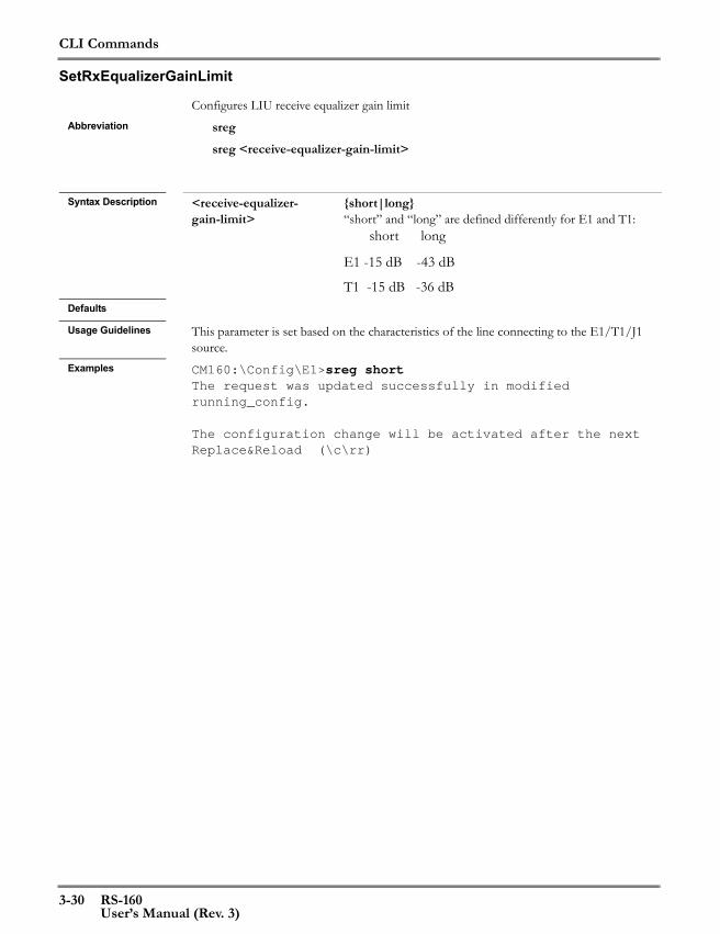
SetRxEqualizerGainLimit
Configures LIU receive equalizer gain limitAbbreviation sreg
sreg <receive-equalizer-gain-limit>
Syntax Description <receive-equalizer-
gain-limit> {short|long}“short” and “long” are defined differently for E1 and T1: short long
E1 -15 dB -43 dB
T1 -15 dB -36 dBDefaults
Usage Guidelines This parameter is set based on the characteristics of the line connecting to the E1/T1/J1 source.
Examples CM160:\Config\E1>sreg shortThe request was updated successfully in modified running_config.
The configuration change will be activated after the next Replace&Reload (\c\rr)

CLI Commands
RS-160 3-31User’s Manual (Rev. 3)
SetStaticIP
Sets the static IP address of a selected interface (either LAN or UPLINK)Abbreviation ssip
ssip <IP-address>
Syntax Description <IP-address> IP address of the selected interface in the format
“nn.nn.nn.nn.”, where nn is a number from 0 to 255Defaults
Usage Guidelines An IP of all zeroes is invalid. Any other value is accepted.Examples CM160:\Config\UPLINK>ssip 100.10.200.45
The request was updated successfully in modified running_config.
The configuration change will be activated after the next Replace&Reload (\c\rr)
CLI Commands
3-32 RS-160User’s Manual (Rev. 3)
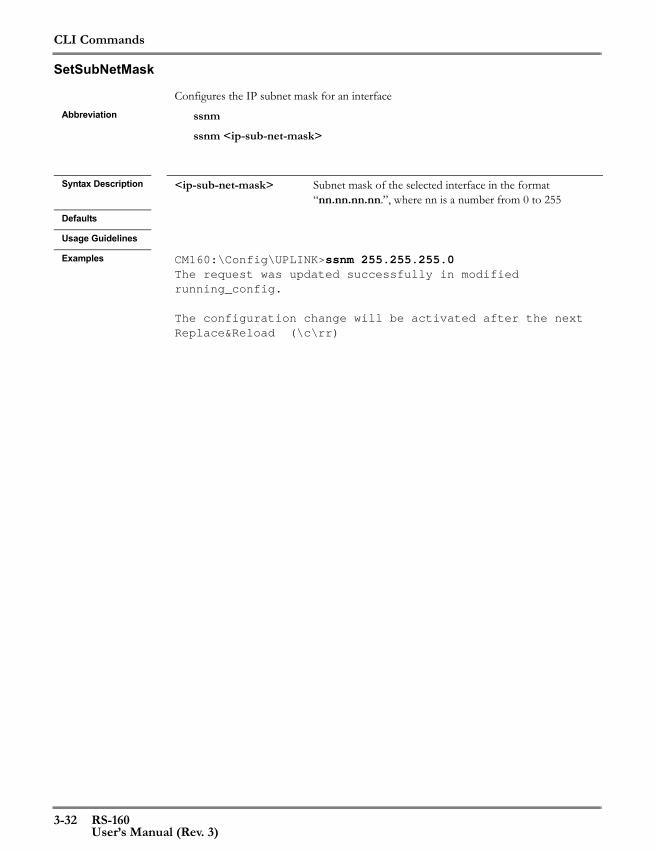
SetSubNetMask
Configures the IP subnet mask for an interfaceAbbreviation ssnm
ssnm <ip-sub-net-mask>
Syntax Description <ip-sub-net-mask> Subnet mask of the selected interface in the format
“nn.nn.nn.nn.”, where nn is a number from 0 to 255Defaults
Usage Guidelines
Examples CM160:\Config\UPLINK>ssnm 255.255.255.0The request was updated successfully in modified running_config.
The configuration change will be activated after the next Replace&Reload (\c\rr)

CLI Commands
RS-160 3-33User’s Manual (Rev. 3)
GetConfig
Configuration information for LAN or UPLINKCM160:\Config\UPLINK>gc
Running_config Modified Running_config
Working mode.......: ETH ETH MII/RMII...........: MII MII AutoNeg............: On On Speed (Mb/s).......: - - Duplex mode........: - - Flow control.......: Disabled Disabled Clock source.......: DTE DTE RMII ref clock out.: - - Interface BW (kb/s): Unlimited Unlimited MAC address........: 00-50-C2-15-89-A0 00-50-C2-15-89-A0 MAC loopback.......: Disabled Disabled PHY configured.....: Yes Yes PHY number.........: 0 0
Returns configuration information about an interface or an applicationAbbreviation gc
gc
Syntax Description
Defaults
Usage Guidelines The function returns a different report based on the sub-directory where the function is called.
Examples Configuration information for an interface configured as bitstream:CM160:\Config\E1>gc
Running_config Modified Running_config
Working mode...............: Bitstream Bitstream Frame size (bytes).........: 96 96 Underrun value.............: 0xFE 0xFE Clocking mode..............: Loopback-master Loopback-master Tx clock polarity..........: Rising Rising Rx clock polarity..........: Falling Falling Interface loopback.........: Disabled Disabled LIU line format............: E1 E1 LIU type...................: DS2155 DS2155 LIU line code..............: HDB3 HDB3 LIU line build out.........: E1_75 E1_75 LIU Rx term................: 120ohm 120ohm LIU monitor gain...........: Norm Norm LIU Rx equalizer gain limit: Short Short LIU jitter attenuation.....: Disabled Disabled LIU loopback...............: Disabled Disabled Framed mode................: Unframed Unframed

CLI Commands
3-34 RS-160User’s Manual (Rev. 3)
GetConfig (continued) Advertisement...........: 10H 10F 100H 100F 10H 10F 100H 100F IP address..............: 169.254.1.5 169.254.1.5 Subnet mask.............: 255.255.255.0 255.255.255.0
CONSOLE configuration information:CM160:\Config\CONSOLE>gc
Running_config Modified Running_config Baud rate..........: 115200 115200 Stop bit...........: 1 1 Protocol...........: Term Term Mode...............: Enabled Enabled
TDM Over Packet application configuration information:CM160:\Config\TDM_Over_Packet>gc
Running_config Modified Running_config
Subscriber interface.........: E1 E1 Service interface............: UP UP Header type..................: RTP RTP Local port...................: 2000 2000 Target port..................: 2000 2000 Local IP address.............: 169.254.1.5 169.254.1.5 Target IP address............: 169.254.1.5 169.254.1.6 IP TOS.......................: 0 0 Payload length (bytes/frames): 96 96 Ethertype....................: 0x800 0x800 Maximum jitter (ms)..........: 50 50 Clock lock range (ppm).......: 50 50 Reorder......................: Disabled Disabled VLAN support.................: Disabled Disabled VLAN ID......................: 0 0 VLAN priority................: 0 0 Framed mode..................: Unframed Unframed
Bridging application configuration information:CM160:\Config\Bridging_Service>gc
Running_config Modified Running_config
Bridge interface...: LAN LAN Bridge mode........: ON ON Aging time (sec)...: 30 30 Mac table size.....: 1024 1024

CLI Commands
RS-160 3-35User’s Manual (Rev. 3)
GetStatus
Operational status of the bitstream interface (E1 or T1):CM160:\Config\E1>gs
Status of interfaceLink.....................: UPAlarm Status.............: -LIU loopback.............: DisableInterface loopback.......: Disable
Additional formats are described on the following page.
Returns the operational status of a selected interface or of the overall systemAbbreviation gs
gs [r]
Syntax Description [r] optional reset of TDM Over Packet statisticsDefaults
Usage Guidelines The status returned depends on the directory where the command is executed. The command returns a different status for an interface operating as an Ethernet port or as a bitstream port. The TDM Over Packet application has its own status report. Enter “gs r” to reset the jitter overflow and underflow counts in the TDM Over Packet report. Examples of all the “gs” reports are shown below.
Examples Operational status of an Ethernet interface (UPLINK or LAN):CM160:\Config\UPLINK>gs
Status of interfaceLink ....................: UPPHY status...............: WorkingAutoNeg..................: DonePeer advertisement value.: 43E1Speed (Mb/s).............: 100Duplex mode..............: FULLFlow control.............: OFFMAC loopback.............: Disabled

CLI Commands
3-36 RS-160User’s Manual (Rev. 3)
GetStatus (continued)Display status of the TDM Over Packet application
CM160:\Config\TDM_Over_Packet>gs Item Value/Status
Clocking mode...................: Loopback-master Connectivity....................: UP Rx path.........................: UP Current jitter buffer delay (ms): 4.970 Jitter overflow.................: 0 Jitter underflow................: 1 Bandwidth utilization(kb/s).....: 2476 Successful recoveries...........: 0 Recovery process starts.........: 0 Successful Rx Paths.............: 1 Jitter minimum level (ms).......: 4.970 Jitter maximum level (ms).......: 5.467 Peer reachable..................: YES Peer MAC address................: 00-50-C2-15-42-60 Peer ping round-trip time (ms)..: 7 CES application test mode.......: -
The “Connectivity” parameter is “UP” when packetized bitstream data is being forwarded to the paired RS-160. The parameter is “DOWN” when no packets are being sent, due to no bitstream data being received on E1/T1.The “Peer reachable” parameter is “YES” when the RS-160 has successfully received a response to a “ping’ of the paired RS-160.
Display of the status of the Bridging application:CM160:\Config\Bridging_Service>gs
No. of entries currently in MAC addr. table......: 17 Max no. in table since last reset................: 23
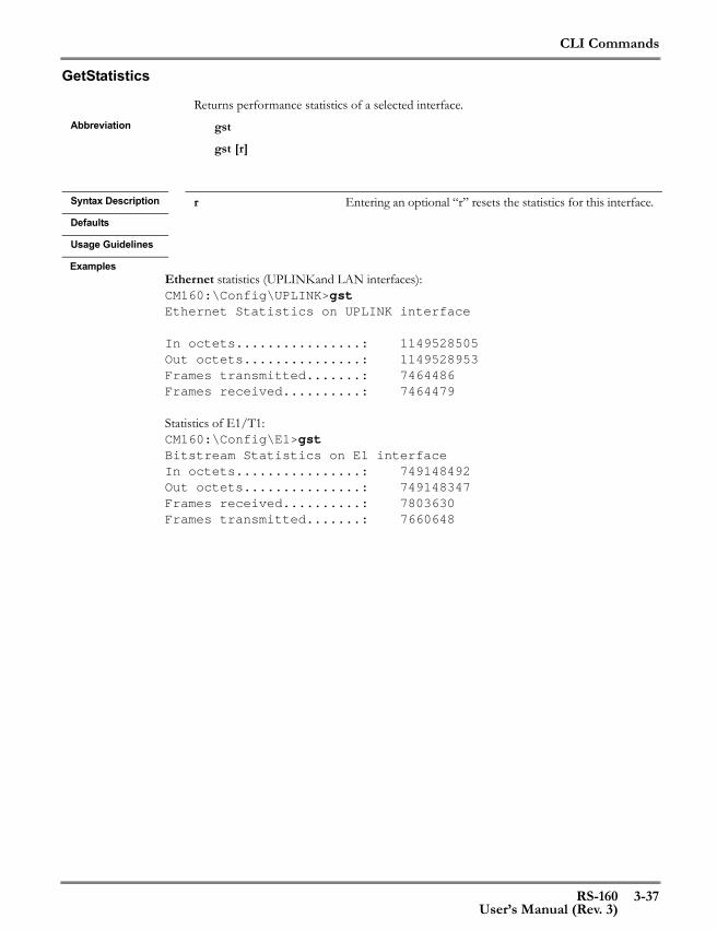
CLI Commands
RS-160 3-37User’s Manual (Rev. 3)
GetStatistics
ExamplesEthernet statistics (UPLINKand LAN interfaces):CM160:\Config\UPLINK>gstEthernet Statistics on UPLINK interface
In octets................: 1149528505Out octets...............: 1149528953Frames transmitted.......: 7464486Frames received..........: 7464479
Statistics of E1/T1:CM160:\Config\E1>gstBitstream Statistics on E1 interfaceIn octets................: 749148492Out octets...............: 749148347Frames received..........: 7803630Frames transmitted.......: 7660648
Returns performance statistics of a selected interface.Abbreviation gst
gst [r]
Syntax Description r Entering an optional “r” resets the statistics for this interface.Defaults
Usage Guidelines
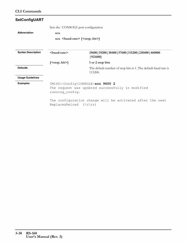
CLI Commands
3-38 RS-160User’s Manual (Rev. 3)
SetConfigUART
Sets the CONSOLE port configurationAbbreviation scu
scu <baud-rate> [<stop_bit>]
Syntax Description <baud-rate> {9600|19200|38400|57600|115200|230400|460800
|921600}[<stop_bit>] 1 or 2 stop bits
Defaults The default number of stop bits is 1. The default baud rate is 115200.
Usage Guidelines
Examples CM160:\Config\CONSOLE>scu 9600 2The request was updated successfully in modified running_config.
The configuration change will be activated after the next Replace&Reload (\c\rr)

CLI Commands
RS-160 3-39User’s Manual (Rev. 3)
SetConfigCESProtocol
ExamplesThe following examples configure first for RTP protocol, then for the Minimal protocol. The port numbers are changed automatically to values that are correct for the protocol.CM160:\Config\TDM_Over_Packet>ccap rtp 0x800 2000 2002The request was updated successfully in modified running_config.
The configuration change will be activated after the next Replace&Reload (\c\rr)CM160:\Config\TDM_Over_Packet>gc
Running_config Modified Running_config
Subscriber interface.........: E1 E1Service interface............: UP UPHeader type..................: RTP RTPLocal port...................: 2000 2000Target port..................: 2000 2002Local IP address.............: 10.101.1.225 10.101.1.225Target IP address............: 10.101.1.226 10.101.1.226IP TOS.......................: 0 0Payload length (bytes/frames): 96 96Ethertype....................: 0x800 0x800Maximum jitter (ms)..........: 5 5Clock lock range (ppm).......: 50 50Reorder......................: Disabled DisabledVLAN support.................: Disabled DisabledVLAN ID......................: 0 0VLAN priority................: 0 0Framed mode..................: Unframed Unframed
Sets the TDM over Packet CES header format and other parametersAbbreviation ccap
ccap <Protocol>[<Ethertype> <Local_Port> <Target_ Port>]
Syntax Description <Protocol> {RTP|Minimal} Header format for PSN packets.
[<Ethertype>] hexadecimal value; 0x800 for RTP; 0x0600 - 0xFFFF for Minimal (0xF1FF is the default value for Minimal)
[<Local_Port>] decimal value (2000 to 65535) for RTP; 0 to 15 for Minimal
[<Target_ Port>] decimal value (2000 to 65535) for RTP; 0 to 15 for MinimalDefaults
Usage Guidelines A paired RS-160 must be configured with complementary port values and the same protocol and Ethertype as the paired RS-160.

CLI Commands
3-40 RS-160User’s Manual (Rev. 3)
CM160:\Config\TDM_Over_Packet>CM160:\Config\TDM_Over_Packet>ccap minimalThe request was updated successfully in modified running_config.
The configuration change will be activated after the next Replace&Reload (\c\rr)CM160:\Config\TDM_Over_Packet>gc
Running_config Modified Running_config
Subscriber interface.........: E1 E1 Service interface............: UP UP Header type..................: RTP Minimal Local port...................: 2000 1 Target port..................: 2000 0 Local IP address.............: 10.101.1.225 10.101.1.225 Target IP address............: 10.101.1.226 10.101.1.226 IP TOS.......................: 0 0 Payload length (bytes/frames): 96 96 Ethertype....................: 0x800 0xFF1F Maximum jitter (ms)..........: 5 5 Clock lock range (ppm).......: 50 50 Reorder......................: Disabled Disabled VLAN support.................: Disabled Disabled VLAN ID......................: 0 0 VLAN priority................: 0 0 Framed mode..................: Unframed Unframed
CLI Commands
RS-160 3-41User’s Manual (Rev. 3)
SetConfigCESIP
Sets the TDM over Packet application IP configuration Abbreviation ccip
ccip <target_ip_address> [<local_port> <target_port> <ip_tos_value]
Syntax Description <target_ip_address> IP address of the target RS-160 in the format
“nn.nn.nn.nn.”, where nn is a number from 0 to 255
<local_port> decimal value (2000 to 65535) for RTP; 0 to 15 for Mini-mal
<target_port> decimal value (2000 to 65535) for RTP; 0 to 15 for Mini-mal
<ip_tos_value> Value of the IP Type of Service field (0 to 7)Defaults
Usage Guidelines The target IP is required so that the RS-160 can identify the paired RS-160. This is required for both the RTP header and the minimal header. The local and target port numbers must be complementary to the port settings on the paired RS-160.
Examples CM160:\Config\TDM_Over_Packet>ccip 200.120.34.08 5 2004 2006The request was updated successfully in modified running_config.
The configuration change will be activated after the next Replace&Reload (\c\rr)

CLI Commands
3-42 RS-160User’s Manual (Rev. 3)
SetConfigCESPayLength
CM160:\Config\TDM_Over_Packet>ccpl 20Invalid max jitterPossible correct values:
Payload-length-in-frames=20, max-jitter between (13 - 2000).Max-jitter=5, payload-length-in-frames between (1 - 8).
Configures the TDM over Packet application payload sizeAbbreviation ccpl
ccpl <payload_length> [<max_jitter>]
Syntax Description <payload_length> Unframed: Number of bytes in the payload of the CES
packets after all headers. With the Minimal header, the range is 42 to 1492 bytes. With the RTP header, must be a multiple of the E1/J1 (32 bytes) or T1 (24 bytes) frame size. The range for E1/J1 is 32 to 1440. The range for T1 is 24 to 1440.Full or Framed: Number of frames in the payload of the CES packet. The application will calculate the number of bytes based on the frame length and, in the case of Framed, the number of timeslots selected for transmission.
<max_jitter> 0 to 6200 msec - The maximum jitter can be changed optionally with this command. It is an estimate of the maxi-mum jitter (+ or -). For example, a setting of 50 milliseconds results in a range from 0 to 100 msec. This parameter deter-mines the length of the jitter buffer used to smooth the effects of distortion due to network congestion, timing drift, or route changes. The jitter buffer delays the arriving pack-etized bitstream so that the end user experiences a clear con-nection with very little distortion.
Defaults Default payload length is 96 bytes (unframed) or three frames (framed or full).Usage Guidelines The payload length and the maximum jitter combine to define the length of the jitter
buffer. The jitter buffer is also impacted by the clock rate of the data and whether packet reordering is enabled. This function will return a message with the valid range of max jitter and payload length if an invalid value is entered.
Examples The example is in Unframed mode, so the packet length is in bytes:CM160:\Config\TDM_Over_Packet>ccpl 512The request was updated successfully in modified running_config.
The configuration change will be activated after the next Replace&Reload (\c\rr)In the following example, the header format is minimal, the framing mode is Full E1, the maximum jitter is set to 5 msec.

CLI Commands
RS-160 3-43User’s Manual (Rev. 3)
SetConfigCESClock
Configures the TDM over Packet application maximum jitter Abbreviation cclk
cclk <max_jitter> [<payload-length>]
Syntax Description <max_jitter> 0 to 6200 msec - Estimate of the maximum jitter (+ or -). For example, a setting of 50 milliseconds results in a range of 0 to 100 msec. This parameter determines the length of the jitter buffer used to smooth the effects of distortion due to network congestion, timing drift, or route changes. The jitter buffer delays the arriving packetized bitstream so that the end user experiences a clear connection with very little distortion.
<payload-length> 24-1492 bytes - The payload length can be changed optionally with this command. See “SetConfigCESPayLength” on page 3-42
Defaults
Usage Guidelines The maximum jitter and the payload length combine to define the length of the jitter buffer. The jitter buffer is also impacted by the clock rate of the data and whether packet reordering is enabled. This function will return a message with the valid range of max jitter and payload length if an invalid value is entered.
Examples CM160:\Config\TDM_Over_Packet>cclk 50 The request was updated successfully in modified running_config.
The configuration change will be activated after the next Replace&Reload (\c\rr)
In the following example, the header is set to minimal, the line format is E1 (2.048 Mbps) unframed, and packet reordering is disabled:CM160:\Config\TDM_Over_Packet>cclk 5000 42
Invalid max jitter
Possible correct values:Payload-length-in-bytes=42, max-jitter between (1 - 131).Max-jitter=4675, payload-length-in-bytes between (1496 - 1496).
CLI Commands
3-44 RS-160User’s Manual (Rev. 3)
SetConfigCESVlan
Sets the TDM over Packet application VLAN configurationAbbreviation ccvl
ccvl <vlan_mode> [<vlan_id> <vlan_priority> ]
Syntax Description <vlan_mode> {Enable|Disable}<vlan_id> 0 to 4095<vlan_priority> 0 to 7
Defaults VLAN is disabled by default.Usage Guidelines When a virtual LAN is defined for the TDM over packet data, the priority can be raised (0
is the highest priority) to ensure that the TDM data has first use of the available bandwidth.Examples CM160:\Config\TDM_Over_Packet>ccvl enable 2000 0
The request was updated successfully in modified running_config.
The configuration change will be activated after the next Replace&Reload (\c\rr)

CLI Commands
RS-160 3-45User’s Manual (Rev. 3)
SetCESreOrder
Enables and disables the TDM over Packet application packet reorder feature. Abbreviation scr
scr <reorder-feature>
Syntax Description <reorder-feature> {Enable|Disable}Defaults
Usage Guidelines This feature monitors packets containing encapsulated TDM data and transmits them according to an embedded sequence number, not necessarily in the order that they were received. When a packet with the right sequence number was not received, underrun bytes will be sent in place of the bytes in the missing packet. The length of the jitter buffer deter-mines how late a packet has to be before it is replaced with a packet’s worth of filler charac-ters. If the packet arrives late, past the time when it should have been transmitted, it will be discarded.
Examples CM160:\Config\TDM_Over_Packet>scr enable
The request was updated successfully in modified running_config.
The configuration change will be activated after the next Replace&Reload (\c\rr)
CLI Commands
3-46 RS-160User’s Manual (Rev. 3)
SetConfigCESClockRange
Adjusts the TDM over Packet application clock lock range used during clock recovery Abbreviation cclr
cclr <clock-lock-range>
Syntax Description <clock-lock-range> 10-300 ppmDefaults 50 ppmUsage Guidelines This command sets the maximum variation from the nominal frequency associated with
the line format. This parameter is used when the RS-160 performs clock recovery. Use a value other than the standard 50 ppm when system conditions require a wider or narrower variation.
Examples CM160:\Config\TDM_Over_Packet>cclr 100
The request was updated successfully in modified running_config.
The configuration change will be activated after the next Replace&Reload (\c\rr)

CLI Commands
RS-160 3-47User’s Manual (Rev. 3)
SetTimeSlots
Replaces the current list of time slots with a new list of timeslotsAbbreviation sts
sts <list_of_timeslots>
Syntax Description <list_of_timeslots> individual time slots separated by a space and/or one or
more ranges of timeslots separated by a “-”E1 time slots are numbered 0 to 31T1 time slots are numbered 1 to 24
Defaults
Usage Guidelines The number of time slots selected impact the size of the transmitted packet, since the packet payload is a defined number of frames X the number of selected time slots. An error message will be displayed if there is a problem with the resulting payload size.
Examples The following T1 example shows multiple ranges can be entered and that time slots do not have to be entered in ascending order. The resulting assignments are displayed with the gfts command.CM160:\Config\TDM_Over_Packet>sts 12-24 10 1 3-6The request was updated successfully in modified running_config.
The configuration change will be activated after the next Replace&Reload (\c\rr)CM160:\Config\TDM_Over_Packet>gfts
TimeSlot# 00---0----1----1----2---- 01---5----0----5----0----
Running_config -------------------------Modified Running_config fX-XXXX---X-XXXXXXXXXXXXX
X : Selected- : Not selected* : Not applicableF : framing information in-bandf : framing information out-of-bandS : signaling information in-bands : signaling information out-of-band

CLI Commands
3-48 RS-160User’s Manual (Rev. 3)
AddTimeSlots
Adds time slots to the existing list of time slotsAbbreviation ats
ats <list_of_timeslots>
Syntax Description <list_of_timeslots> individual time slots separated by a space and/or one or
more ranges of timeslots separated by a “-”E1 time slots are numbered 0 to 31T1 time slots are numbered 1 to 24
Defaults
Usage Guidelines The number of time slots selected impact the size of the transmitted packet, since the packet payload is a defined number of frames X the number of selected time slots. An error message will be displayed if there is a problem with the resulting payload size.
Examples The following example adds time slot 8 to the example on the preceding page and displays the new set of defined time slots.CM160:\Config\TDM_Over_Packet>ats 8
The request was updated successfully in modified running_config.
The configuration change will be activated after the next Replace&Reload (\c\rr)
CM160:\Config\TDM_Over_Packet>gfts
TimeSlot# 00---0----1----1----2---- 01---5----0----5----0----
Running_config -------------------------Modified Running_config fX-XXXX-X-X-XXXXXXXXXXXXX
X : Selected- : Not selected* : Not applicableF : framing information in-bandf : framing information out-of-band
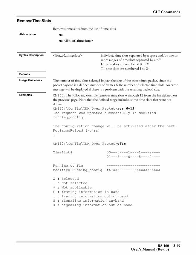
CLI Commands
RS-160 3-49User’s Manual (Rev. 3)
RemoveTimeSlots
Removes time slots from the list of time slotsAbbreviation rts
rts <list_of_timeslots>
Syntax Description <list_of_timeslots> individual time slots separated by a space and/or one or
more ranges of timeslots separated by a “-”E1 time slots are numbered 0 to 31T1 time slots are numbered 1 to 24
Defaults
Usage Guidelines The number of time slots selected impact the size of the transmitted packet, since the packet payload is a defined number of frames X the number of selected time slots. An error message will be displayed if there is a problem with the resulting payload size.
Examples CM160:The following example removes time slots 6 through 12 from the list defined on the previous page. Note that the defined range includes some time slots that were not defined.CM160:\Config\TDM_Over_Packet>rts 6-12The request was updated successfully in modified running_config.
The configuration change will be activated after the next Replace&Reload (\c\rr).
CM160:\Config\TDM_Over_Packet>gfts
TimeSlot# 00---0----1----1----2---- 01---5----0----5----0----
Running_config -------------------------Modified Running_config fX-XXX-------XXXXXXXXXXXX
X : Selected- : Not selected* : Not applicableF : framing information in-bandf : framing information out-of-bandS : signaling information in-bands : signaling information out-of-band

CLI Commands
3-50 RS-160User’s Manual (Rev. 3)
SetCESAppTestMode
Sets the test mode for the TDM Over Packet CES applicationAbbreviation sctm
sctm [<side> <mode>]
Syntax Description <side> {UP|E1}
<mode> {Enable|Disable}Defaults Entering sctm with no parameters enables loopback testing without a second RS-160Usage Guidelines This command must be executed to do loopbck testing using only one RS-160. Enter
sctm up enable so that the TDM Over PAcket application will send and receive data with-out a paired unit.
Examples CM160:\Config\TDM_Over_Packet>sctm up enableCES test is being activated on service sideThe command completed successfully.
CLI Commands
RS-160 3-51User’s Manual (Rev. 3)
GetCesRecoveryHistory
Displays a report of up to twenty recovery actionsAbbreviation gch
gch [<num_of_records>]
Syntax Description <num_of_records> 1 to 20Defaults If no parameter is entered, all recovery records will be displayed.Usage Guidelines Recovery records are not saved across a restart of the product. This functions if for test
and debugging purposes.Examples CM160:\Config\TDM_Over_Packet>gch
No data to display in recovery history
CLI Commands
3-52 RS-160User’s Manual (Rev. 3)
SetBridging
Enables/disables the bridging service on the LAN interfaceAbbreviation sb
sb <mode>
Syntax Description <mode> {Enable|Disable}Defaults
Usage Guidelines This function starts and stops the bridging service. The service learns source MAC addresses on received packets and filters packets that are addressed to those MACs. This eliminates unnecessary traffic from being transmitted on the UPLINK interface.Bridging activates immediately. Perform a ResetReload (\c\rr) so that bridging is activated on every restart.
Examples CM160:\Config\Bridging_Service>sb enable
The command completed successfully.
The request was updated successfully in modified running_config.
CLI Commands
RS-160 3-53User’s Manual (Rev. 3)
SetAgingTime
Sets bridging aging timeAbbreviation sat
sat <aging-time-seconds>
Syntax Description <aging-time-seconds> {10-3600}Defaults 30 secondsUsage Guidelines The bridging service maintains a table of up to 1024 source MAC addresses. If no packets
are received from one of the addresses after a period of time, it may be that the station at that address is no longer active (for example, in a wireless LAN environment, a user has moved from one location to another). The aging time determines how long a MAC must be inactive before it is removed from the source MAC table. An aging time change is activated immediately. Perform a ResetReload (\c\rr) so that the selected aging time is activated on every restart.
Examples CM160:\Config\Bridging_Service>sat 300
The command completed successfully.
The request was updated successfully in modified running_config.
CLI Commands
3-54 RS-160User’s Manual (Rev. 3)
ClearBridging
Clears all entries in the bridging service source MAC address tableAbbreviation cb
cb
Syntax Description
Defaults
Usage Guidelines When the table has been cleared, the service will re-learn any active MAC addresses on the LAN interface.
Examples CM160:\Config\Bridging_Service>cb
Clearing bridging table data succeeded

CLI Commands
RS-160 3-55User’s Manual (Rev. 3)
SetDefGateway
Sets the default Gateway IP addressAbbreviation sdg
sdg <default-GW-IP-address>
Syntax Description <default-GW-IP-address> IP address of the default gateway in the format
“nn.nn.nn.nn.”, where nn is a number from 0 to 255Defaults 10.101.1.1Usage Guidelines This parameter is required when sending messages to IP addresses that are not on the local
subnet.Examples CM160:\Config\General>sdg 50.45.123.01
The request was updated successfully in modified running_config.
The configuration change will be activated after the next Replace&Reload (\c\rr)

CLI Commands
3-56 RS-160User’s Manual (Rev. 3)
GetDefGateway
Returns the default Gateway IP addressAbbreviation gdg
gdg
Syntax Description
Defaults
Usage Guidelines
ExamplesCM160:\Config\General>gdg
Running_config Modified Running_config
Default gateway IP addr: 10.101.1.1 50.45.123.1

CLI Commands
RS-160 3-57User’s Manual (Rev. 3)
SetMacAddress
Sets the UPLINK and LAN MAC addresses and saves them in Flash memoryAbbreviation sma
sma <MAC_addr_of_UPLINK>
Syntax Description <MAC_addr_of_
UPLINK>Hexadecimal MAC address in the following format 00-nn-nn-nn-nn-nn
Defaults
Usage Guidelines The LAN MAC address will be one up from the UPLINK MAC address. The RS-160 MAC address is built in to the unit but it can be changed with this command. In normal cir-cumstances, this command should never be used. The MAC address is not provided by the configuration database, so it must be configured via this command.
Examples CM160:\Config\General>sma 00-50-C2-15-03-0aThe configuration change will be activated after the next Replace&Reload (\c\rr)
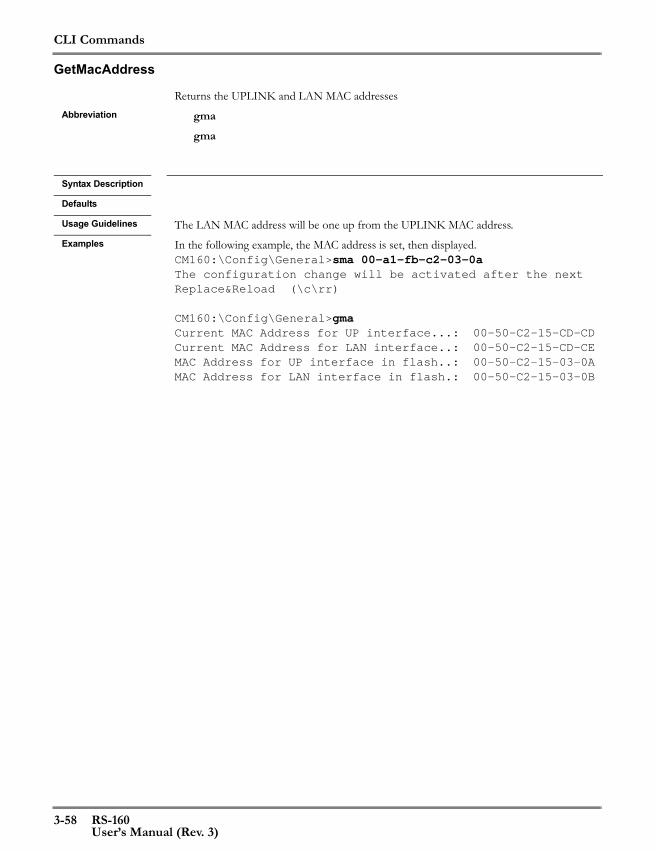
CLI Commands
3-58 RS-160User’s Manual (Rev. 3)
GetMacAddress
Returns the UPLINK and LAN MAC addresses Abbreviation gma
gma
Syntax Description
Defaults
Usage Guidelines The LAN MAC address will be one up from the UPLINK MAC address. Examples In the following example, the MAC address is set, then displayed.
CM160:\Config\General>sma 00-a1-fb-c2-03-0aThe configuration change will be activated after the next Replace&Reload (\c\rr)
CM160:\Config\General>gmaCurrent MAC Address for UP interface...: 00-50-C2-15-CD-CDCurrent MAC Address for LAN interface..: 00-50-C2-15-CD-CEMAC Address for UP interface in flash..: 00-50-C2-15-03-0AMAC Address for LAN interface in flash.: 00-50-C2-15-03-0B

CLI Commands
RS-160 3-59User’s Manual (Rev. 3)
AddRequestManager
Adds a community name to the list of those supported by SNMPAbbreviation arm
arm <mngr_comm_name> <ip_addr> [<permission_level>]
Syntax Description <mngr_comm_name> String of one to 15 characters defining community name.
The string must be bounded by double quotes (” “) if there are any embedded spaces in the community name.
<ip_addr> IP address of new request community nn.nn.nn.nn, where nn is a value from 1 to 255
<permission_level> {G|GS} Defines the community as read-only or read-writeDefaults
Usage Guidelines The user can define up to a total of fifteen manager communities. The manager ID dis-played by the community name is used when the community is to be removed from the list.
Examples CM160:\Config\SNMP>arm remote_comm 1.2.3.4 gsThe request was updated successfully in active ConfigDBCM160:\Config\SNMP>grmMngr ID Mngr Community name IP addr Permission---- -- ------------------- ------- ----------1 remote_comm 1.2.3.4 get/set

CLI Commands
3-60 RS-160User’s Manual (Rev. 3)
RemoveRequestManager
Removes a request community name from the SNMP list of communitiesAbbreviation rrm
rrm <manager_id>
Syntax Description <manager_id> Identification of the ID number of the request manager to be
removed; display the ID number of a request manager by executing the grm function
Defaults
Usage Guidelines
Examples CM160:\Config\SNMP>rrm 2The request was updated successfully in active ConfigDB
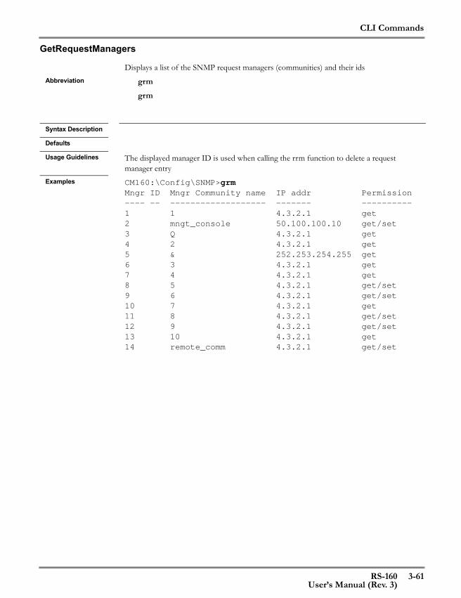
CLI Commands
RS-160 3-61User’s Manual (Rev. 3)
GetRequestManagers
Displays a list of the SNMP request managers (communities) and their idsAbbreviation grm
grm
Syntax Description
Defaults
Usage Guidelines The displayed manager ID is used when calling the rrm function to delete a request manager entry
Examples CM160:\Config\SNMP>grmMngr ID Mngr Community name IP addr Permission---- -- ------------------- ------- ----------1 1 4.3.2.1 get2 mngt_console 50.100.100.10 get/set3 Q 4.3.2.1 get4 2 4.3.2.1 get5 & 252.253.254.255 get6 3 4.3.2.1 get7 4 4.3.2.1 get8 5 4.3.2.1 get/set9 6 4.3.2.1 get/set10 7 4.3.2.1 get11 8 4.3.2.1 get/set12 9 4.3.2.1 get/set13 10 4.3.2.1 get14 remote_comm 4.3.2.1 get/set
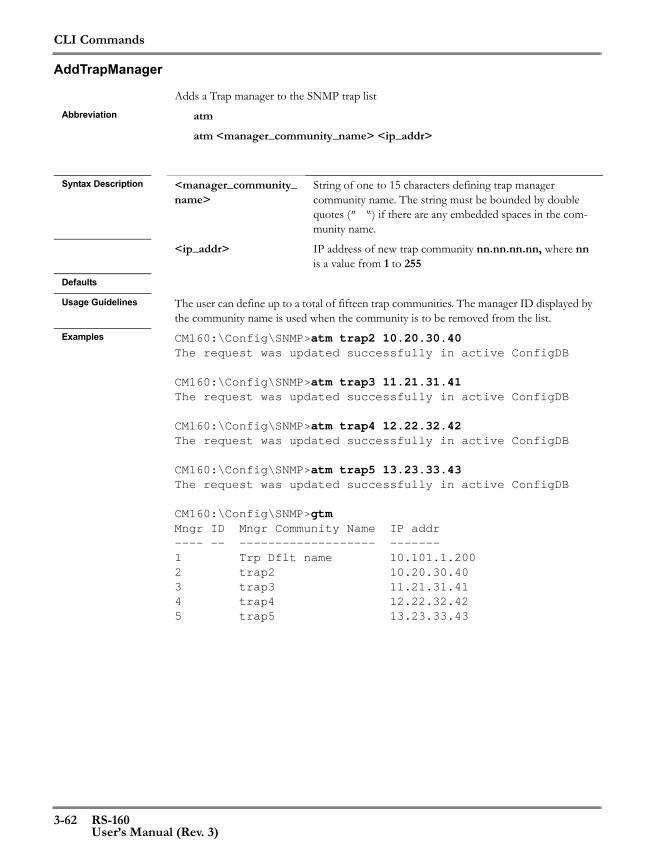
CLI Commands
3-62 RS-160User’s Manual (Rev. 3)
AddTrapManager
Adds a Trap manager to the SNMP trap listAbbreviation atm
atm <manager_community_name> <ip_addr>
Syntax Description <manager_community_
name>String of one to 15 characters defining trap manager community name. The string must be bounded by double quotes (” “) if there are any embedded spaces in the com-munity name.
<ip_addr> IP address of new trap community nn.nn.nn.nn, where nn is a value from 1 to 255
Defaults
Usage Guidelines The user can define up to a total of fifteen trap communities. The manager ID displayed by the community name is used when the community is to be removed from the list.
Examples CM160:\Config\SNMP>atm trap2 10.20.30.40The request was updated successfully in active ConfigDB
CM160:\Config\SNMP>atm trap3 11.21.31.41The request was updated successfully in active ConfigDB
CM160:\Config\SNMP>atm trap4 12.22.32.42The request was updated successfully in active ConfigDB
CM160:\Config\SNMP>atm trap5 13.23.33.43The request was updated successfully in active ConfigDB
CM160:\Config\SNMP>gtmMngr ID Mngr Community Name IP addr---- -- ------------------- -------1 Trp Dflt name 10.101.1.2002 trap2 10.20.30.403 trap3 11.21.31.414 trap4 12.22.32.425 trap5 13.23.33.43

CLI Commands
RS-160 3-63User’s Manual (Rev. 3)
RemoveTrapManager
Removes a manager from the list of SNMP Trap managersAbbreviation rtm
rtm <manager_id>
Syntax Description <manager_id> Identification of the ID number of the trap manager to be
removed; display the ID number of a trap manager by exe-cuting the gtm function
Defaults
Usage Guidelines
Examples In the following example, after listing the Trap communities, the second in the list is removed. Displaying the list again shows that the remaining communities retain the same ID that they had before the community was deleted.CM160:\Config\SNMP>gtmMngr ID Mngr Community Name IP addr---- -- ------------------- -------1 Trp Dflt name 10.101.1.2002 trap2 10.20.30.403 trap3 11.21.31.414 trap4 12.22.32.425 trap5 13.23.33.43\Config\SNMP>rtm 2The request was updated successfully in active ConfigDB
CM160:\Config\SNMP>gtmMngr ID Mngr Community Name IP addr---- -- ------------------- -------1 Trp Dflt name 10.101.1.2003 trap3 11.21.31.414 trap4 12.22.32.425 trap5 13.23.33.43
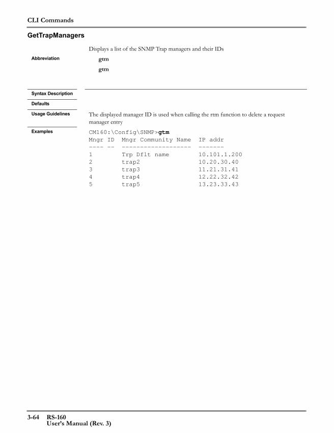
CLI Commands
3-64 RS-160User’s Manual (Rev. 3)
GetTrapManagers
Displays a list of the SNMP Trap managers and their IDsAbbreviation gtm
gtm
Syntax Description
Defaults
Usage Guidelines The displayed manager ID is used when calling the rtm function to delete a request manager entry
Examples CM160:\Config\SNMP>gtmMngr ID Mngr Community Name IP addr---- -- ------------------- -------1 Trp Dflt name 10.101.1.2002 trap2 10.20.30.403 trap3 11.21.31.414 trap4 12.22.32.425 trap5 13.23.33.43

CLI Commands
RS-160 3-65User’s Manual (Rev. 3)
SetRequestPort
Sets the SNMP request port to a specific valueAbbreviation srp
srp <port>
Syntax Description <port> The port can be any value between 1 and 65,535Defaults The default request port is 161Usage Guidelines
Examples CM160:\Config\SNMP>srp 2000The request was updated successfully in modified running_config.
The configuration change will be activated after the next Replace&Reload (\c\rr)

CLI Commands
3-66 RS-160User’s Manual (Rev. 3)
GetRequestTrapPorts
Displays the SNMP request port and trap portAbbreviation gp
gp
Syntax Description
Defaults
Usage Guidelines
ExamplesCM160:\Config\SNMP>gp Current config Next start up config Request port.......: 161 2000 Trap port..........: 162 162
CLI Commands
RS-160 3-67User’s Manual (Rev. 3)
SetTrapPort
Sets the SNMP Trap port to a selected valueAbbreviation stp
stp <trap-port>
Syntax Description <trap-port> The port can be any value between 1 and 65,535Defaults The default trap port is 162Usage Guidelines When the port is changed, the new value is written to the configuration database. The
change does not take effect until the next reset.
Examples CM160:\Config\SNMP>stp 3000The request was updated successfully in active ConfigDB
Reset required to make the configuration effective

CLI Commands
3-68 RS-160User’s Manual (Rev. 3)
DumpMemRange
Displays the contents of a range of memory locationsAbbreviation dmr
dmr <from_addr> [<to_addr>]
Syntax Description <from_addr> Starting address in hexadecimal format (0xnnnnn)
<to_addr> Ending address in hexadecimal format (must be greater than the start address)
Defaults
Usage Guidelines This command is for debug purposes only. Reading certain memory addresses can cause a system reset. Use with caution!
Examples

CLI Commands
RS-160 3-69User’s Manual (Rev. 3)
DumpMemLength
Displays the contents of a defined number of memory locations starting at a defined location
Abbreviation dmldml <from_addr> [<length>]
Syntax Description <from_addr> Starting address in hexadecimal format (0xnnnnnnnn)<length> optional decimal value of the number of locations to dump
rounded up to the next multiple of 16.Defaults If no length is supplied, the function will return 48 locationsUsage Guidelines This command is for debug purposes only. Reading certain memory addresses can cause a
system reset. Use with caution!Examples
CLI Commands
3-70 RS-160User’s Manual (Rev. 3)
ShowFreeHeapSize
Displays the size of the available HeapAbbreviation sfh
sfh
Syntax Description
Defaults
Usage Guidelines
Examples CM160:\Diagnostics\Debug>sfhAvailable memory size is 2439176.
CLI Commands
RS-160 3-71User’s Manual (Rev. 3)
SetTraceLevel
Sets the trace level for built-in error and debugging messagesAbbreviation stl
stl <new_level>
Syntax Description <new_level> -1 to 6
0: No SWERRs and no traces-1: SWERRs and no traces1 to 6: SWERRs plus traces of the same level and below
Defaults
Usage Guidelines
Examples CM160:\Diagnostics\Debug>stl 3The command completed successfully.
CLI Commands
3-72 RS-160User’s Manual (Rev. 3)
SetTraceMessageType
Sets the output format of trace messagesAbbreviation stmt
stmt <format>
Syntax Description <format> {F|MP|MO}
F: Full reportMP: Message and parametersMO: Message only
Defaults
Usage Guidelines
Examples CM160:\Diagnostics\Debug>stmt mpThe command completed successfully.

CLI Commands
RS-160 3-73User’s Manual (Rev. 3)
ClearSwerrs
Clears the table of SWERR messagesAbbreviation cs
cs
Syntax Description
Defaults
Usage Guidelines
Examples CM160:\Diagnostics\Debug>csThe command completed successfully.
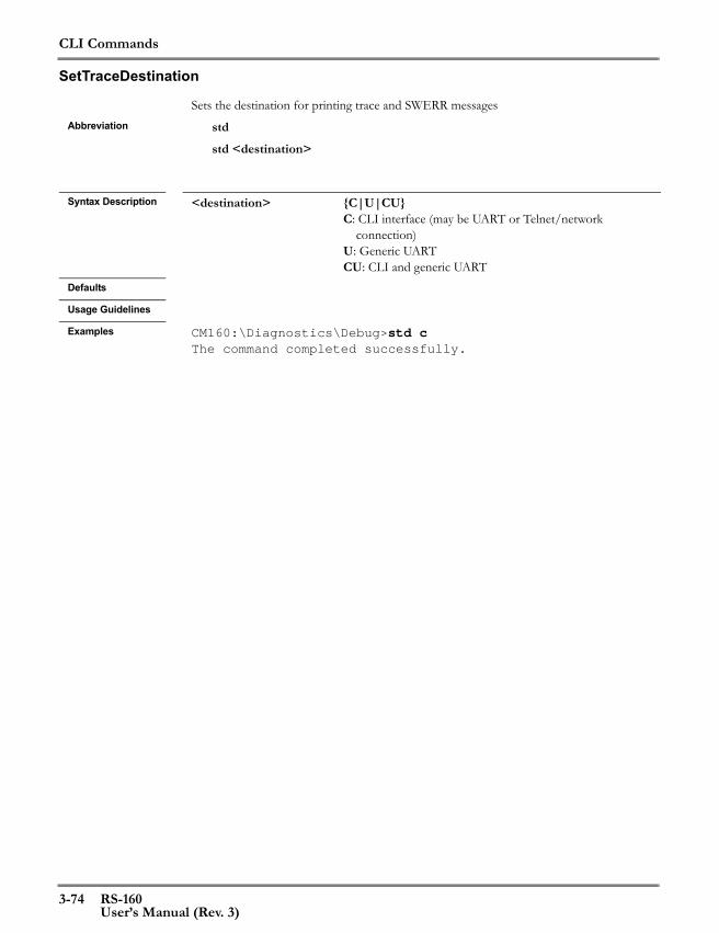
CLI Commands
3-74 RS-160User’s Manual (Rev. 3)
SetTraceDestination
Sets the destination for printing trace and SWERR messagesAbbreviation std
std <destination>
Syntax Description <destination> {C|U|CU}
C: CLI interface (may be UART or Telnet/network connection)
U: Generic UARTCU: CLI and generic UART
Defaults
Usage Guidelines
Examples CM160:\Diagnostics\Debug>std cThe command completed successfully.
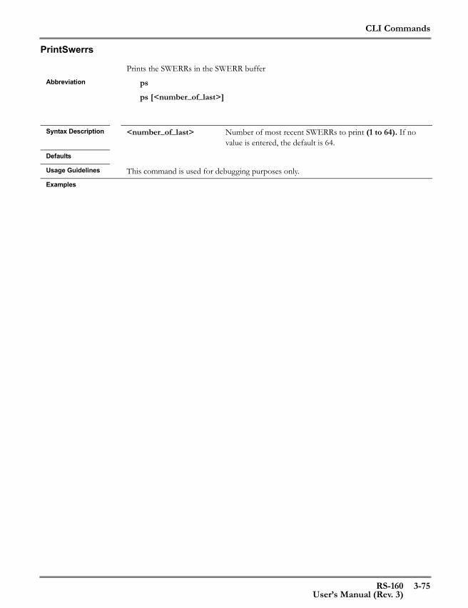
CLI Commands
RS-160 3-75User’s Manual (Rev. 3)
PrintSwerrs
Prints the SWERRs in the SWERR bufferAbbreviation ps
ps [<number_of_last>]
Syntax Description <number_of_last> Number of most recent SWERRs to print (1 to 64). If no
value is entered, the default is 64.Defaults
Usage Guidelines This command is used for debugging purposes only.Examples

CLI Commands
3-76 RS-160User’s Manual (Rev. 3)
GetTraceStatus
Returns trace settingsAbbreviation gts
gts
Syntax Description
Defaults
Usage Guidelines
Examples CM160:\Diagnostics\Debug>gts
Agos trace level...: 1 Swerrs.............: Enabled Output level.......: Full Destination........: -
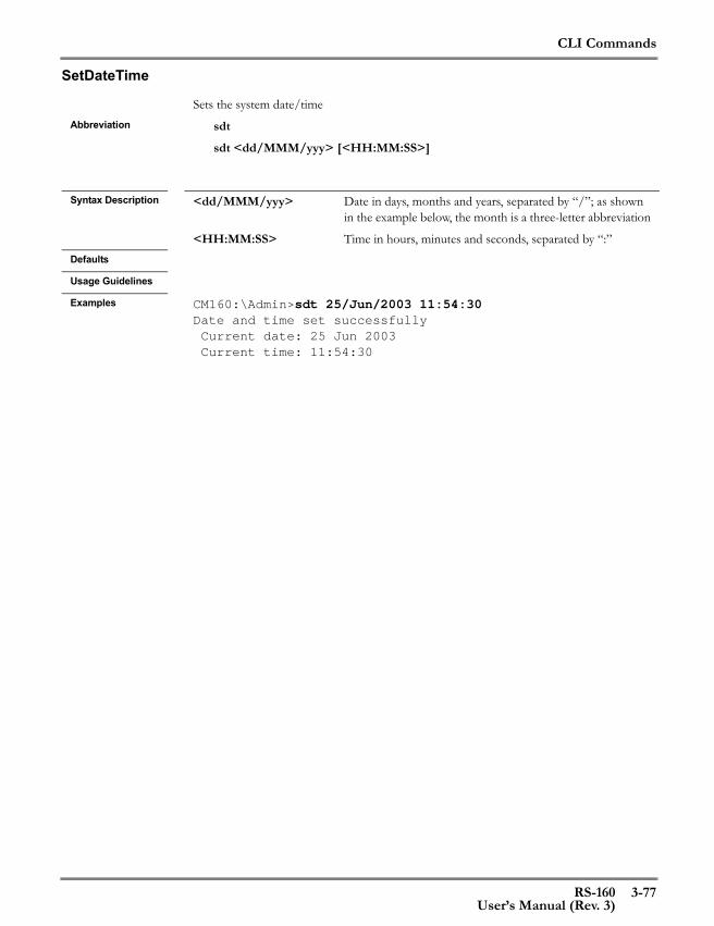
CLI Commands
RS-160 3-77User’s Manual (Rev. 3)
SetDateTime
Sets the system date/timeAbbreviation sdt
sdt <dd/MMM/yyy> [<HH:MM:SS>]
Syntax Description <dd/MMM/yyy> Date in days, months and years, separated by “/”; as shown
in the example below, the month is a three-letter abbreviation
<HH:MM:SS> Time in hours, minutes and seconds, separated by “:”Defaults
Usage Guidelines
Examples CM160:\Admin>sdt 25/Jun/2003 11:54:30Date and time set successfully Current date: 25 Jun 2003 Current time: 11:54:30

CLI Commands
3-78 RS-160User’s Manual (Rev. 3)
GetDateTime
Returns the current date and timeAbbreviation gdt
gdt
Syntax Description
Defaults
Usage Guidelines
Examples CM160:\Admin>gdt Current date: 25 Jun 2003 Current time: 11:55:58

CLI Commands
RS-160 3-79User’s Manual (Rev. 3)
GetVersion
Returns the version of the RS-160 firmwareAbbreviation gv
gv
Syntax Description
Defaults
Usage Guidelines
Examples CM160:\Config>gvCM160 R01.01.02_D002-200

CLI Commands
3-80 RS-160User’s Manual (Rev. 3)
SetMemory
Set a memory address to a valueAbbreviation sm
sm <address> <value>
Syntax Description <address> memory address in hexadecimal format (0xnnnnnnn)
<value> value of the 32-bit location in hexadecimal format (0xnnnnnnnn)
Defaults
Usage Guidelines The starting address will be aligned to a 32-bit address.This command is for debug purposes only. Writing to certain memory addresses can cause a system reset. Use with caution!
Examples

CLI Commands
RS-160 3-81User’s Manual (Rev. 3)
SetMemoryRange
Sets a range of memory addresses to a selected valueAbbreviation smr
smr <from_address> <to_address> <value>
Syntax Description <from_address> start memory address in hexadecimal format (0xnnnnnnn)
<to_address> end memory address in hexadecimal format (0xnnnnnnn)<value> value to be written, in hexadecimal format (0xnnnnnnnn)
Defaults
Usage Guidelines This command is for debug purposes only. Writing to certain memory addresses can cause a system reset. Use with caution!
Examples
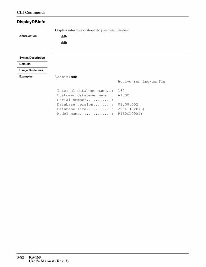
CLI Commands
3-82 RS-160User’s Manual (Rev. 3)
DisplayDBInfo
Displays information about the parameter databaseAbbreviation ddb
ddb
Syntax Description
Defaults
Usage Guidelines
Examples \Admin>ddb Active running-config
Internal database name..: 160 Customer database name..: A100C Serial number...........: Database version........: 01.00.002 Database size...........: 2934 (0xb76) Model name..............: R160CL00A1Y

CLI Commands
RS-160 3-83User’s Manual (Rev. 3)
GetBoardData
Returns information about the RS-160 internal circuit board configuration.Abbreviation gbd
gbd
Syntax Description
Defaults
Usage Guidelines
Examples CM160:\Admin>gbd Board information
Detect card.............: Enabled Card type...............: 100TE CPLD version............: 0 Board PLL type..........: no PLL“The Detect card” parameter within the RS-160 device, if enabled in the database, makes the additional check of the card type, CPLD version and presence of a PLL. (Standard RS-160 cards do not have a PLL). If there is a PLL, this function returns the PLL type as well (T1 or E1).

CLI Commands
3-84 RS-160User’s Manual (Rev. 3)
FunctionalTest
Starts an internal self-test that runs continuously or for a defined durationAbbreviation fts
fts [<time>]
Syntax Description <time> <1-65,535 seconds> The number of iterations, at one
iteration per secondzero: continuous operationno value entered: 10 iterations
Defaults continuous operationUsage Guidelines This test exercises the RS-160 by routing traffic through all the device interfaces and check-
ing for correct performance. The command performs a device reset before the test and after the test.The following setup must be done for the function to operate successfully:1. Connect LAN to UPLINK with a cross-cable.2. Connect a loopback connector to the E1/T1 connector. 3. While the command is running, RS-160 SYS OK LED displays the status of the test:
• When the LED is lit continuously, it indicates the test is proceeding without error• A repeated pattern of two short ons followed by a long off indicates the test has
detected a failure4. If the test was set to run continuously or for a long interval, the user can cycle power to
stop the test5. When the test completes the device is reset and the version string is sent to the Console
Examples The following output is displayed with a successful test:CM160:\Diagnostics>fts 2Board Test: successful iteration: 0Board Test: successful iteration: 1Board Test: ENDED SUCCESSFULLYCM160 R01.01.02_D002-200
The following output is displayed when there is no loopback on the E1/T1 port:CM160:\Diagnostics>fts 2Board Test: successful iteration: 0Failed interface: 2, in-frames=0, frames-discards=0, bytes-discards=0**** SELF TEST FAILED **** (continue scan) : 1Board Test: TEST FAILED!!!!!!!:CM160 R01.01.02_D002-200
CLI Commands
RS-160 3-85User’s Manual (Rev. 3)
SetDefaultDB
Sets the RS-160 startup configuration database to a default state based on the line format and the Tx clock source
Abbreviation sddbsddb <line-format> <Tx-clock-source> [<model_template>]
Syntax Description <line-format> {E1|T1|J1}
<Tx-clock-source> {RECOVERY|LOOPBACK} “RECOVERY” uses the clock calculated from received bitstream packets as the Tx clock (the other RS-160 is the Master)“LOOPBACK” uses the local LIU clock, which is based on its E1 or T1 connection, as the Tx clock (this RS-160 is the Master)
<model-template> optional model template; this will set the default parameters for this model
Defaults
Usage Guidelines This command sets an RS-160 to a default status. It should be used only for initial configuration of the device. Any individual parameter changes in the modified running-config will be lost.See Appendix A, Default Database for the default database parameters and the default values for the line format/Tx clock source combinations.
Examples CM160:Admin>sddb e1 loopbackThe command completed successfully.
The request was updated successfully in startup-config.
Reload is required to make the configuration effective ('\c\rl')

CLI Commands
3-86 RS-160User’s Manual (Rev. 3)
SetUARTMDP
Sets a selected serial interface to the Maintenance Download Protocol. until the next reset.Abbreviation smd
smd <UART>
Syntax Description <UART> {CONS|CON2|UA|UB}
Selects which serial interface will be used (Console or console 2, UART A or UART B). The CONSOLE port is the only port available externally on the RS-160
Defaults
Usage Guidelines This command is used when the RS-160 application image is not running on the Flash and the image must be updated. Note that this command has an immediate effect.
Examples CM160:\Diagnostics\Debug>smd consA response message will be displayed only if the CLI connection is not via the serial inter-face that is re-configured by this command.
CLI Commands
RS-160 3-87User’s Manual (Rev. 3)
SetDynamicMACLpbk
Enables/disables loopback in the MAC. The directory from where the command is run determines which MAC is set to loopback (UPLINK or LAN).
Abbreviation sdmlsdml <MAC-loopback-mode>
Syntax Description <MAC-loopback-mode> {ON|OFF}Defaults OFFUsage Guidelines This command is for test and debug purposes only.. Note that this command has an immedi-
ate effect. Examples CM160:\Config\UPLINK>sdml on
The command completed successfully.

CLI Commands
3-88 RS-160User’s Manual (Rev. 3)
SetBitstreamDynLpbk
Configures the bitstream interface for loopback operations until the next device resetAbbreviation sbdl
sbdl <loop-mode>
Syntax Description <loop-mode> {Local+Tx|Local|Remote+Rx|Remote|Dual}
Local: Transmitted traffic is looped back and received.Remote: Received traffic is looped back and retransmitted.Local+Tx: Transmitted traffic is looped back and received. It is also transmitted externally.Remote+Rx: Received traffic is looped back and retransmit-ted. It is also received by the RS-160 processor.
Defaults
Usage Guidelines This command is for test and debug purposes only. Note that this command has an imme-diate effect. Once a loopback mode is set it stays in place until the next device reset.
Examples CM160:\Config\E1>sbdl local+txThe command completed successfully.
CLI Commands
RS-160 3-89User’s Manual (Rev. 3)
SetLIUDynamicLpbk
Configures the internal line interface unit (LIU) for loopback until the next device resetAbbreviation sldl
sldl <LIU-loopback-mode>
Syntax Description <LIU-loopback-mode> {Dual|Local|Remote|Analog}
Local: Transmitted traffic is looped back and received.Remote: Received traffic is looped back and retransmitted.Dual: Performs both local and remote loopback.Analog: Not applicable
Defaults
Usage Guidelines Analog mode does not apply to the RS-160. Local and Dual mode only operate when the Tx clock is in Recovery (slave) mode. Once a loopback mode is selected, it stays in place until the next device reset.
Examples CM160:\Config\E1>sldl remoteThe command completed successfully.
CLI Commands
3-90 RS-160User’s Manual (Rev. 3)
SetUARTRCP
Sets a selected UART to accept RCP (Redux Control Protocol) messages (the messaging application) until the next device reset. After reset the UART will return to the last setting of the UART.
Abbreviation sursur <UART>
Syntax Description <UART> {CONS|CON2|UA|UB}
Selects which serial interface will be used (Console or con-sole 2, UART A or UART B). The CONSOLE port is the only port available externally on the RS-160
Defaults
Usage Guidelines This command is used by the Management Console to temporarily switch into RCP mode to do a database upload or download.
Examples CM160:\Diagnostics\Debug>sur cons
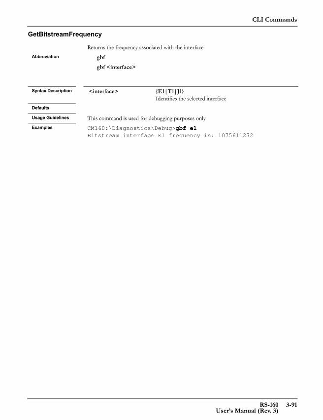
CLI Commands
RS-160 3-91User’s Manual (Rev. 3)
GetBitstreamFrequency
Returns the frequency associated with the interfaceAbbreviation gbf
gbf <interface>
Syntax Description <interface> {E1|T1|J1}
Identifies the selected interfaceDefaults
Usage Guidelines This command is used for debugging purposes onlyExamples CM160:\Diagnostics\Debug>gbf e1
Bitstream interface E1 frequency is: 1075611272
CLI Commands
3-92 RS-160User’s Manual (Rev. 3)

RS-160 4-1User’s Manual (Rev. 3)
4 Control Protocol
This Redux Control Protocol (RCP) is a CPU-to-CPU messaging interface to theRS-160. The user can control the RS-160 and request status from it with binarymessages without having to create or interpret the text messages used in the CLI. TheRCP parallels the CLI and, in fact, performs many of the same functions. The names ofcommands in the RCP are the same as the corresponding CLI functions.
The RS-160 CD contains a PC-based sample program. The source code of this programdemonstrates use of the RCP to control and request status from the RS-160.
Connecting to the RCPThe RCP is accessed as an application on one of the RS-160 serial interfaces. When aUART is configured with the Messaging application, messages received on the UARTare assumed to be in RCP format and are interpreted accordingly.
The RS-160 also supports RCP messages received over TCP. It processes RCP messagessent to a network interface (Interface C only in Release 1.0), addressed to the interfaceIP address and encapsulated in TCP, with a target port of 2100.
Message OverviewThere are three types of messages:
• Call messages - Messages sent from a host CPU to the RS-160• Response messages - The RS-160 sends a response message to the host CPU after
processing any call message• Unsolicited messages - messages sent from the RS-160 to the host without a pre-
ceding call message (There are no unsolicited messages in Release 1.0 of theRS-160)
Message FormatThe general message format is shown in Table 4-1. Each message has a unique ID(listed in Table 4-2 on page 4-3) sent in the first two bytes. The message type, containedin the next two bytes, is one of the three types listed above. The next field contains themessage payload length in bytes. This is followed by a status field, then by the payloaditself.
All messages, including call messages, have a status field. The status in a call message isalways an acknowledge (ACK.). Response messages return a status value that reports onthe success or otherwise of the corresponding call message.
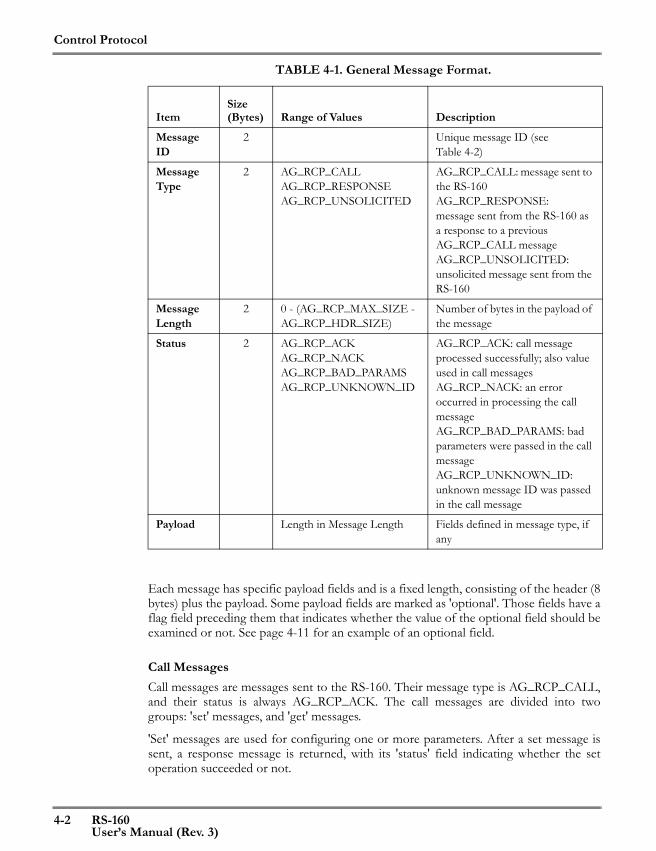
Control Protocol
4-2 RS-160User’s Manual (Rev. 3)
TABLE 4-1. General Message Format.
Each message has specific payload fields and is a fixed length, consisting of the header (8bytes) plus the payload. Some payload fields are marked as 'optional'. Those fields have aflag field preceding them that indicates whether the value of the optional field should beexamined or not. See page 4-11 for an example of an optional field.
Call MessagesCall messages are messages sent to the RS-160. Their message type is AG_RCP_CALL,and their status is always AG_RCP_ACK. The call messages are divided into twogroups: 'set' messages, and 'get' messages.
'Set' messages are used for configuring one or more parameters. After a set message issent, a response message is returned, with its 'status' field indicating whether the setoperation succeeded or not.
ItemSize (Bytes) Range of Values Description
Message ID
2 Unique message ID (seeTable 4-2)
Message Type
2 AG_RCP_CALL AG_RCP_RESPONSE AG_RCP_UNSOLICITED
AG_RCP_CALL: message sent to the RS-160 AG_RCP_RESPONSE: message sent from the RS-160 as a response to a previous AG_RCP_CALL message AG_RCP_UNSOLICITED: unsolicited message sent from the RS-160
Message Length
2 0 - (AG_RCP_MAX_SIZE - AG_RCP_HDR_SIZE)
Number of bytes in the payload of the message
Status 2 AG_RCP_ACK AG_RCP_NACK AG_RCP_BAD_PARAMSAG_RCP_UNKNOWN_ID
AG_RCP_ACK: call message processed successfully; also value used in call messagesAG_RCP_NACK: an error occurred in processing the call messageAG_RCP_BAD_PARAMS: bad parameters were passed in the call messageAG_RCP_UNKNOWN_ID: unknown message ID was passed in the call message
Payload Length in Message Length Fields defined in message type, if any

Control Protocol
RS-160 4-3User’s Manual (Rev. 3)
'Get' messages are used for querying configuration parameters. After a 'get' message issent, a response message is returned with a payload containing the requestedinformation.
Response MessagesResponse messages are messages sent from the target, as a response to a previous callmessage. The message ID is that of the corresponding call message. The message type isAG_RCP_RESPONSE, and the status can be one of the following:
• AG_RCP_ACK - The call message was received and processed successfully• AG_RCP_NACK - An error occurred while receiving and processing the corre-
sponding call message• AG_RCP_BAD_PARAMS - At least one of the parameters in the call message
was erroneous• AG_RCP_UNKNOWN_ID - The message ID in the call message was unknown
If the previous call message was a 'set' message, the response message usually willcontain no payload. See “SetConfigEth Response” on page 4-51 for an exception to this.
If the previous call message was a 'get' message, the payload of the response messagewill contain the requested data.
Unsolicited MessagesUnsolicited messages are messages sent from the RS-160 without previous call message.There are no unsolicited messages defined in RS-160 Release 1.0.
Message IDsEach RCP message has a unique message ID. Table 4-2 lists all the IDs, and theirassociated function, and a brief description of the function. See the correspondingfunction in See Chapter 3, CLI Commands, for a discussion of the parametersassociated with a command.
TABLE 4-2. Functions and RCP Message IDs
Function Message IDMessage Description
SetConfigEth AG_RCP_SET_CFG_ETH_MSG_ID (0x200) (See page 4-11)
SetConfigEthFlowControl AG_RCP_SET_CFG_ETH_FLOW_MSG_ID (0x203) (See page 4-12)
SetConfigEthLoopback AG_RCP_SET_CFG_ETH_LPBK_MSG_ID (0x205) (See page 4-13)
GetEthStatus AG_RCP_GET_ETH_STATUS_MSG_ID (0x207) (See page 4-14)
GetConfigEth AG_RCP_GET_CFG_ETH_MSG_ID (0x208) (See page 4-15)
SetConfigBitStream AG_RCP_SET_CFG_BS_MSG_ID (0x400) (See page 4-16)
SetConfigBitStreamClkSrc AG_RCP_SET_CFG_BS_CLK_SRC_MSG_ID (0x401) (See page 4-17)

Control Protocol
4-4 RS-160User’s Manual (Rev. 3)
SetConfigBitStreamUnderVal AG_RCP_SET_CFG_BS_UNDRUN_VAL_MSG_ID (0x402)
(See page 4-18)
GetBitStreamStatus AG_RCP_GET_BS_STATUS_MSG_ID (0x403) (See page 4-19)
GetConfigBitStream AG_RCP_GET_CFG_BS_MSG_ID (0x404) (See page 4-20)
SetConfigLIU AG_RCP_SET_CFG_LIU_MSG_ID (0x500) (See page 4-21)
SetConfigLIULineCode AG_RCP_SET_CFG_LIU_LINE_CODE_MSG_ID (0x501)
(See page 4-23)
SetConfigLIUlineBuildout AG_RCP_SET_CFG_LIU_LINE_BLD_OUT_MSG_ID (0x502)
(See page 4-24)
SetConfigLIURxTerm AG_RCP_SET_CFG_LIU_RX_TRM_MSG_ID (0x503) (See page 4-25)
SetConfigJitterAttenuation AG_RCP_SET_CFG_LIU_JITTER_MSG_ID (0x504) (See page 4-26)
SetConfigLIUMonGain AG_RCP_SET_CFG_LIU_MON_GAIN_MSG_ID (0x506) (See page 4-27)
GetLIUStatus AG_RCP_GET_LIU_STATUS_MSG_ID (0x507) (See page 4-28)
GetConfigLIU AG_RCP_GET_CFG_LIU_MSG_ID (0x508) (See page 4-29)
SetStaticIP AG_RCP_SET_STATIC_IP_MSG_ID (0x600) (See page 4-30)
GetStaticIPCfg AG_RCP_GET_STATIC_IP_CFG_MSG_ID (0x601) (See page 4-31)
SetSubNetMask AG_RCP_SET_SUB_NET_MASK_MSG_ID (0x602) (See page 4-32)
GetConfig AG_RCP_GET_CFG_CES_APP_MSG_ID (0xA07) (See page 4-33)
SetConfigUART AG_RCP_SET_CFG_UART_MSG_ID (0x700) (See page 4-36)
SetConfigUARTApp AG_RCP_SET_CFG_UART_APP_MSG_ID (0x701) (See page 4-37)
SetConfigUARTMode AG_RCP_SET_CFG_UART_MODE_MSG_ID (0x702) (See page 4-38)
GetConfigUART AG_RCP_GET_CFG_UART_MSG_ID (0x703) (See page 4-39)
GetVersion AG_RCP_GEN_GET_VERSION_MSG_ID (0x800) (See page 4-40)
SetConfigCESIP AG_RCP_SET_CFG_CES_IP_MSG_ID (0xA01) (See page 4-42)
SetConfigCESProtocol AG_RCP_SET_CFG_CES_PROT_MSG_ID (0xA00) (See page 4-41)
SetConfigCESPayLength AG_RCP_SET_CFG_CES_PAYLD_LEN_MSG_ID (0xA03)
(See page 4-43)
SetConfigCESClock AG_RCP_SET_CFG_CES_CLK_MSG_ID (0xA04) (See page 4-44)
SetConfigCESVlan AG_RCP_SET_CFG_CES_VLAN_MSG_ID (0xA05) (See page 4-45)
GetStatusCesApp AG_RCP_GET_STATUS_CES_APP_MSG_ID (0xA08) (See page 4-34)
ResetCesStatus AG_RCP_RESET_CES_STATUS_MSG_ID (0xA09) (See page 4-35)
DumpMemRange AG_RCP_DUMP_MEM_RANGE_MSG_ID (0xC00) (See page 4-46)
DumpMemLength AG_RCP_DUMP_MEM_LEN_MSG_ID (0xC01) (See page 4-47)
ShowFreeHeapSize AG_RCP_FREE_HEAP_SIZE_MSG_ID (0xC02) (See page 4-48)
Reset AG_RCP_RESET_MSG_ID (0xC03) (See page 4-49)
Function Message IDMessage Description

Control Protocol
RS-160 4-5User’s Manual (Rev. 3)
Response Message FormatTable 4-3 lists the defined response messages. Table 4-4 shows the generic responsemessage sent for any successfully processed call message. The message varies only inthat the message ID is that of the original call message.
TABLE 4-3. List of Response Messages
Function Message IDMessage Description
SetConfigEth Response AG_RCP_SET_CFG_ETH_MSG_ID (See page 4-51)
GetEthStatus Response AG_RCP_GET_ETH_STATUS_MSG_ID (See page 4-52)
GetConfigEth Response AG_RCP_GET_CFG_ETH_MSG_ID (See page 4-53)
GetBitStreamStatus Response AG_RCP_GET_BS_STATUS_MSG_ID (See page 4-55)
GetConfigBitStream Response AG_RCP_GET_CFG_BS_MSG_ID (See page 4-56)
GetLIUStatus Response AG_RCP_GET_LIU_STATUS_MSG_ID (See page 4-57)
GetConfigLIU Response AG_RCP_GET_CFG_LIU_MSG_ID (See page 4-58)
GetStaticIPCfg Response AG_RCP_GET_STATIC_IP_CFG_MSG_ID (See page 4-60)
GetConfig Response AG_RCP_GET_CFG_CES_APP_MSG_ID (See page 4-63)
GetStatusCesApp Response AG_RCP_GET_STATUS_CES_APP_MSG_ID (See page 4-67)
GetConfigUART Response AG_RCP_GET_CFG_UART_MSG_ID (See page 4-61)
GetVersion Response AG_RCP_GEN_GET_VERSION_MSG_ID (See page 4-61)
DumpMemRange Response AG_RCP_DUMP_MEM_RANGE_MSG_ID (See page 4-65)
DumpMemLength Response AG_RCP_DUMP_MEM_LEN_MSG_ID (See page 4-66)
ShowFreeHeapSize Response AG_RCP_FREE_HEAP_SIZE_MSG_ID (See page 4-67)

Control Protocol
4-6 RS-160User’s Manual (Rev. 3)
TABLE 4-4. Generic Response Message
Parameter LogicalsRedux-defined logical parameters have been used for all message parameters exceptthose that require a user-selected numerical value, such as an IP address. The logicals aredefined in the .h files included in the RS-160 CD.
The Redux logicals are all named with the prefix “AG_”. The name allows the systemdesigner to devise his own naming system with concern for conflicting with the Reduxnaming scheme.
RCP Example ProgramThe RCP example program eases the task of creating host code to interact with theRS-160. It implements construction of all the call messages and processes all of theresponse messages. The example program runs on a PC and has a simple user interfaceto allow the system developer to experiment with the RCP commands. The programruns on a PC Running Window 2000 or Windows XP, and compiles with MS VisualC++ 6.0.
The files supplied include a MSVC6.0 workspace and project files. The supplieddirectory structure is shown in Table 4-5.
The project is organized into four libraries:
• Uart library - this library implements the UART communication layer.
ItemSize (Bytes) Range of Values Description
Message ID
2 ID of associated call message
Message Type
2 AG_RCP_RESPONSE
Message Length
2 0
Status 2 AG_RCP_ACK AG_RCP_NACK AG_RCP_BAD_PARAMSAG_RCP_UNKNOWN_ID
AG_RCP_ACK: call message processed successfully; also value used in call messagesAG_RCP_NACK: an error occurred in processing the call messageAG_RCP_BAD_PARAMS: bad parameters were passed in the call messageAG_RCP_UNKNOWN_ID: unknown message ID was passed in the call message

Control Protocol
RS-160 4-7User’s Manual (Rev. 3)
asynch_protocol.c implements the byte stuffing protocol as supported by the RS-160.The function uart_handle_rx_message is called for each received message. Users of this library must provide an implementation of this function.The function uart_send_msg is used to send UART messages.The rest of the .c and .h files that are part of this library are from Microsoft example code for using the UART.generic_uart.dsp is the MSVC6.0 project file for the UART library
• TCP library - this library implements the TCP/IP communication layer.The function ag_client_handle_rx_message is called for each received message. Users of this library must provide an implementation of this func-tion.The function ag_client_send_msg is used to send TCP messages.tcp_client.dsp is the MSVC6.0 project file for the TCP library.
• RCP library - This library implements the formatting of the RCP messages andprovides some abstraction to the underlying communication layer (TCP orUART). Note that RCP message parameters are always in network order.gen_net.c / gen_net.h - This file implements functions for converting net-work order to host order values and vice versa.rcp_gen.c / rcp_gen.h - gives a general layer which encapsulates the com-munication layer (TCP or UART)The function ag_rcp_set_time_out is called in order to wait to a response before sending a new message.The functions ag_rcp_db_load and ag_rcp_db_download implement upload from the RS-160 target into a file and download of a configuration DB file to the RS-160, using lower level RCP messages.rcp_msg_processing.c / rcp_msg_processing.h and all the shwrp_app_rcp_XXX.h files:These files define a function for each RCP message that requests and receives parameters in a user-friendly manner, using enumerations in host order. Each function also gets a pointer to the RCP payload memory which is filled with the correct values. each function returns the payload size.rcp.dsp is the MSVC6.0 project file for the RCP library.
• Rs160 rcp example executable - This is the main application. It provides a com-mand line interface for setting and getting configuration parameters.rs160_rcp_example.c - The main file. rs160_rcp_functions.c - function which gets input from the stdin devicers160_rcp_example.dsp - the MSVC6.0 project file for the overall applica-tionrs160_rcp_example.dsw - this is MSVC6.0 workspace file which includes all the relevant modules.

Control Protocol
4-8 RS-160User’s Manual (Rev. 3)
TABLE 4-5. RCP Sample Program Directory Structure
Creating the Sample ApplicationTo create the sample application:
1. Start the Developer Studio application2. Open the file rs160_rcp_example\rs160_rcp_example.dsw3. Make all the projects by invoking the “[Build] Batch build” command.The libraries and executable are saved at pc_bin\release and pc_bin\debug:
• generic_uart.lib• rcp.lib• tcp_client.lib• rs160_rcp_example.exe
Running the Sample ApplicationRun the application either by connecting via a UART configured to use the messagingapplication or via a network connection.
The user is prompted for a message ID. The user needs to know the hexadecimal valueof the message ID in order to use the application. This value has been included inTable 4-2 with the list of logical message IDs. The application prompts for each messagepayload parameter. The user can then use one of the configuration or status commandsto see the result of a “send” message that changed the value of a database parameter.
The following message is displayed when there has been an error trying to activate thesample program. It provides a guide to calling the program.
Directory Tree Contents
General Redux type definitionsLogicals for each group of commandsLogicals and prototypes for comm layer
Source for RCP librarySource for example programSource for comm layer libraries
Source for UART comm layer librarySource for TCP comm layer library

Control Protocol
RS-160 4-9User’s Manual (Rev. 3)
In the following example, the sample program connects to the RS-160 via TCP/IP.. TheCES get configuration command is executed, the port numbers are changed, and the getconfiguration command re-executed, showing that the ports did change.
rs160_rcp_example.exe tcp ip=10.101.1.225===connecting using TCP to ip/port 10.101.1.225/1025 ===
Done with initializing TCP. server ip is: 10.101.1.225 port is: 2100
Enter message ID. 0x100 to exit0xa07Enter interface: 0 for C, 1 for A, 2 for B2Message ID 0xa07 succeededCes application configuration is (reset may be needed):Header type............: RTPTarget IP address......: 10.101.1.226Subscriber interface...: BService interface......: CIP TOS.................: 0Target port............: 7D2Local port.............: 7D0Ether type.............: 0x0800Payload size...........: 96Max jitter delay.......: 5VLAN mode..............: DisabledVLAN ID................: 65535VLAN priority..........: 51
Enter message ID. 0x100 to exit0xa00Enter interface: 0 for C, 1 for A, 2 for B2Enter protocol (header format) type configuration:0 for RTP1 for Minimal
======================USAGE=======================================rs160_rcp_example.exe <com#|tcp> [baud=#|ip=#.#.#.#] [dbg] com=#: The RS232 port to use. For example com1, com2 etc.
baud=#: The RS232 baud rate. Should be the same as the Rs160 target baud rate Valid values are: 9600,19200,38400,57600,115200 For example baud=115200
tcp: Specifies to use the TCP/IP for communication.
ip=#.#.#.#: Specifies the IP address of the Rs160 target
dbg: tells the program to print communication debug information
for example: rs160_rcp_example.exe com1 baud=115200 dbg connects using com1 with baud rate of 115200 and print debug info. rs160_rcp_example.exe tcp ip=10.100.2.3 connects using TCP/IP to address 10.100.2.3 port 1025==================================================================

Control Protocol
4-10 RS-160User’s Manual (Rev. 3)
0Do you want to determine an Ether Type? 1 for yes, 0 for NO0Do you want to determine a source port? 1 for yes, 0 for NO1Enter local port (hex): 0x800Do you want to determine a target port? 1 for yes, 0 for NO1Enter target port (hex): 0x800Message ID 0xa00 succeeded
Enter message ID. 0x100 to exit0xa07Enter interface: 0 for C, 1 for A, 2 for B2Message ID 0xa07 succeededCes application configuration is (reset may be needed):Header type............: RTPTarget IP address......: 10.101.1.226Subscriber interface...: BService interface......: CIP TOS.................: 0Target port............: 800Local port.............: 800Ether type.............: 0x0800Payload size...........: 96Max jitter delay.......: 5VLAN mode..............: DisabledVLAN ID................: 65535VLAN priority..........: 51
Enter message ID. 0x100 to exit0x
Call Message DescriptionsThe following pages contain descriptions of each call message.

Control Protocol
RS-160 4-11User’s Manual (Rev. 3)
SetConfigEth
Usage GuidelinesThis message sets the Ethernet configuration. When this command configures an interface tooperate using auto-negotiation, the interface will also be configured to use a PHY.All changes will go into effect only after a device reset, except for a change in the speed parameter.The response message indicates whether a reset is required or not. See “SetConfigEth Response” on page 4-51.
ItemSize (Bytes) Range of Values Description
Message ID 2 AG_RCP_SET_CFG_ETH_MSG_ID
Message Type
2 AG_RCP_CALL
Message Length
2 16
Status 2 AG_RCP_ACK
Interface 4 AG_IF_CAG_IF_A
Interface to configure
Speed 4 AG_RCP_ETH_RATE_10 AG_RCP_ETH_RATE_100 AG_RCP_ETH_RATE_AUTO
Interface speed in Mbps, or determined using auto-negotiation
Duplex Flag 4 AG_TRUEAG_FALSE
If AG_TRUE, the next field will be interpreted
Duplex Mode (optional)
4 AG_RCP_ETH_HALF_DUPLEX, AG_RCP_ETH_FULL_DUPLEX
Sets the duplex mode to be half or full

Control Protocol
4-12 RS-160User’s Manual (Rev. 3)
SetConfigEthFlowControl
Usage GuidelinesThis change will go into effect only after a device reset.
ItemSize (Bytes) Range of Values Description
Message ID 2 AG_RCP_SET_CFG_ETH_FLOW_MSG_ID
Message Type
2 AG_RCP_CALL
Message Length
2 8
Status 2 AG_RCP_ACK
Interface 4 AG_IF_CAG_IF_A
Interface to configure
Flow Control Mode
4 AG_RCP_SWITCH_OFFAG_RCP_SWITCH_ON
Sets the interface flow control mode to be on or off

Control Protocol
RS-160 4-13User’s Manual (Rev. 3)
SetConfigEthLoopback
Usage GuidelinesThis change will go into effect only after a device reset.
ItemSize (Bytes) Range of Values Description
Message ID 2 AG_RCP_SET_CFG_ETH_LPBK_MSG_ID
Message Type
2 AG_RCP_CALL
Message Length
2 8
Status 2 AG_RCP_ACK
Interface 4 AG_IF_CAG_IF_A
Interface to configure
Loopback Mode
4 AG_RCP_SWITCH_OFFAG_RCP_SWITCH_ON
Sets the Ethernet inter-face loopback mode to be on or off; this is MAC loopback

Control Protocol
4-14 RS-160User’s Manual (Rev. 3)
GetEthStatus
Usage Guidelines
ItemSize (Bytes) Range of Values Description
Message ID 2 AG_RCP_GET_ETH_STATUS_MSG_ID
Message Type
2 AG_RCP_CALL
Message Length
2 4
Status 2 AG_RCP_ACK
Interface 4 AG_IF_CAG_IF_A
Ethernet interface

Control Protocol
RS-160 4-15User’s Manual (Rev. 3)
GetConfigEth
Usage Guidelines
ItemSize (Bytes) Range of Values Description
Message ID 2 AG_RCP_GET_CFG_ETH_MSG_ID
Message Type
2 AG_RCP_CALL
Message Length
2 4
Status 2 AG_RCP_ACK
Interface 4 AG_IF_CAG_IF_A
Ethernet interface

Control Protocol
4-16 RS-160User’s Manual (Rev. 3)
SetConfigBitStream
Usage GuidelinesThe changes in this command will go into effect only after a device reset.
ItemSize (Bytes) Range of Values Description
Message ID 2 AG_RCP_SET_CFG_BS_MSG_ID
Message Type
2 AG_RCP_CALL
Message Length
2 36
Status 2 AG_RCP_ACK
Interface 4 AG_IF_A, AG_IF_B Interface to configureUnderrun Flag
4 AG_TRUEAG_FALSE
If AG_TRUE, the next field will be interpreted
Underrun Value (optional)
4 1 - AG_RCP_BS_UNDERRUN_VAL_MAX Bit Stream underrun byte value configuration
Tx Clock Source Flag
4 AG_TRUEAG_FALSE
If AG_TRUE, the next field will be interpreted
Tx Clock Source (optional)
4 AG_RCP_WAN_CLOCK_RECOVERY_MODEAG_RCP_WAN_CLOCK_LPBK_MODE
Tx clock source
Tx Clock Polarity Flag
4 AG_TRUEAG_FALSE
If AG_TRUE, the next field will be interpreted
Tx Clock Polarity (optional)
4 AG_RCP_TX_CLOCK_FALLINGAG_RCP_TX_CLOCK_RISING
Tx clock polarity
Rx Clock Polarity Flag
4 AG_TRUEAG_FALSE
If AG_TRUE, the next field will be interpreted
Rx Clock Polarity (optional)
4 AG_RCP_TX_CLOCK_FALLINGAG_RCP_TX_CLOCK_RISING
Rx clock polarity;
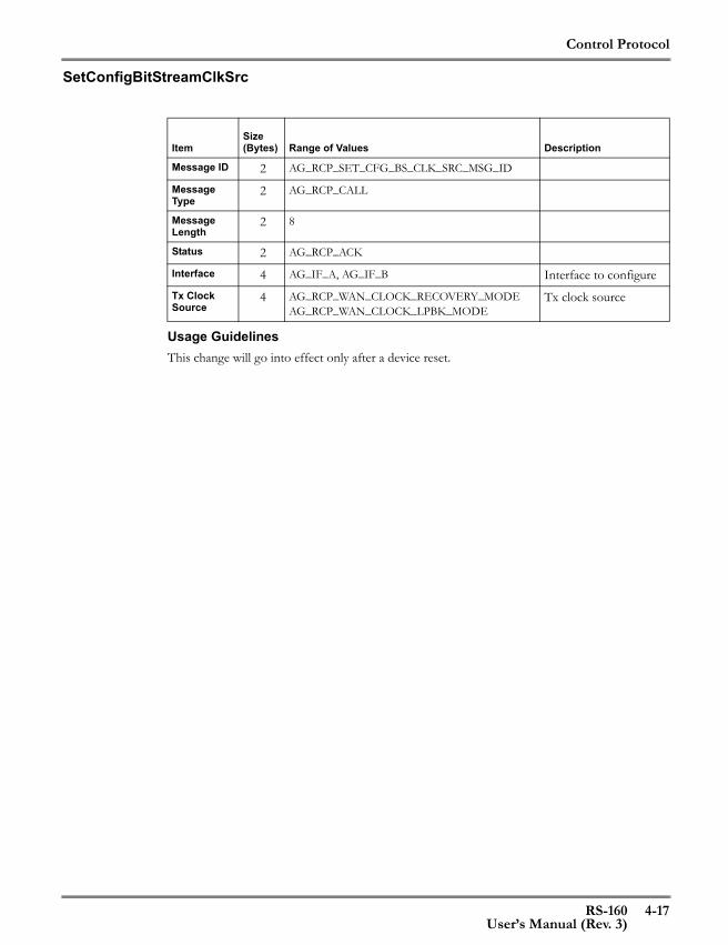
Control Protocol
RS-160 4-17User’s Manual (Rev. 3)
SetConfigBitStreamClkSrc
Usage GuidelinesThis change will go into effect only after a device reset.
ItemSize (Bytes) Range of Values Description
Message ID 2 AG_RCP_SET_CFG_BS_CLK_SRC_MSG_ID
Message Type
2 AG_RCP_CALL
Message Length
2 8
Status 2 AG_RCP_ACK
Interface 4 AG_IF_A, AG_IF_B Interface to configureTx Clock Source
4 AG_RCP_WAN_CLOCK_RECOVERY_MODEAG_RCP_WAN_CLOCK_LPBK_MODE
Tx clock source
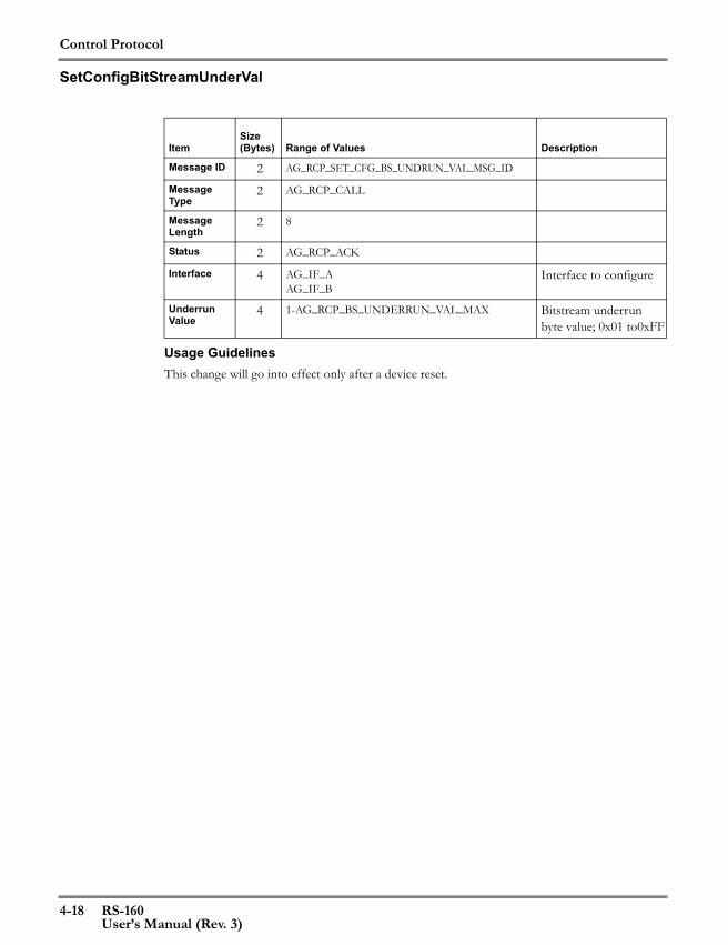
Control Protocol
4-18 RS-160User’s Manual (Rev. 3)
SetConfigBitStreamUnderVal
Usage GuidelinesThis change will go into effect only after a device reset.
ItemSize (Bytes) Range of Values Description
Message ID 2 AG_RCP_SET_CFG_BS_UNDRUN_VAL_MSG_ID
Message Type
2 AG_RCP_CALL
Message Length
2 8
Status 2 AG_RCP_ACK
Interface 4 AG_IF_AAG_IF_B
Interface to configure
Underrun Value
4 1-AG_RCP_BS_UNDERRUN_VAL_MAX Bitstream underrun byte value; 0x01 to0xFF
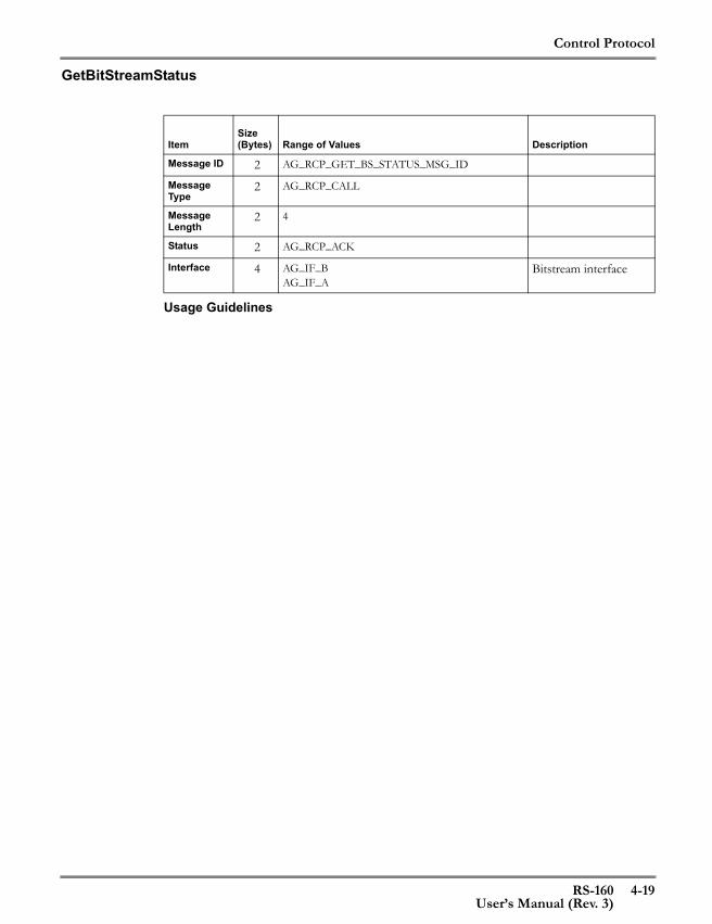
Control Protocol
RS-160 4-19User’s Manual (Rev. 3)
GetBitStreamStatus
Usage Guidelines
ItemSize (Bytes) Range of Values Description
Message ID 2 AG_RCP_GET_BS_STATUS_MSG_ID
Message Type
2 AG_RCP_CALL
Message Length
2 4
Status 2 AG_RCP_ACK
Interface 4 AG_IF_BAG_IF_A
Bitstream interface
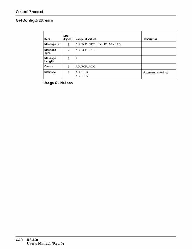
Control Protocol
4-20 RS-160User’s Manual (Rev. 3)
GetConfigBitStream
Usage Guidelines
ItemSize (Bytes) Range of Values Description
Message ID 2 AG_RCP_GET_CFG_BS_MSG_ID
Message Type
2 AG_RCP_CALL
Message Length
2 4
Status 2 AG_RCP_ACK
Interface 4 AG_IF_BAG_IF_A
Bitstream interface
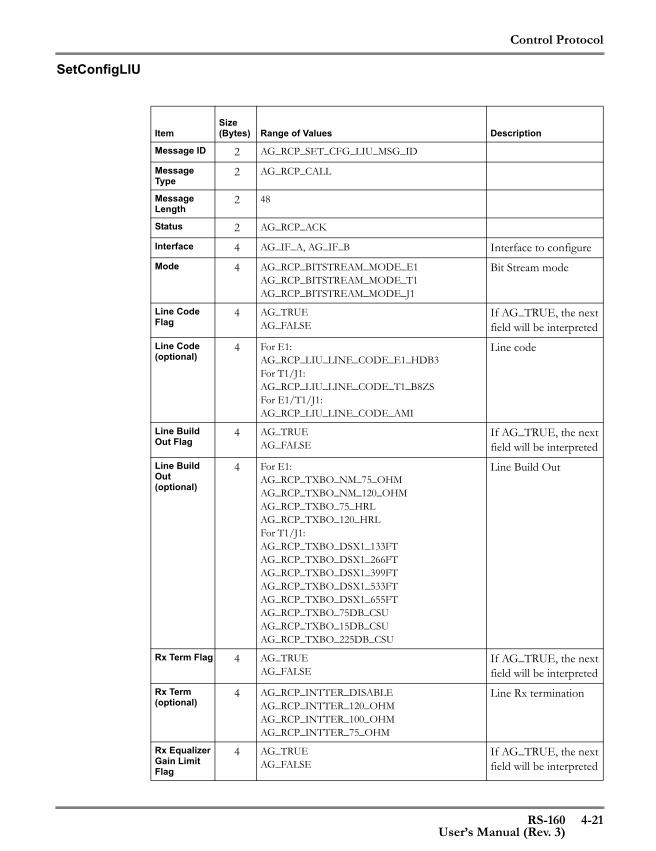
Control Protocol
RS-160 4-21User’s Manual (Rev. 3)
SetConfigLIU
ItemSize (Bytes) Range of Values Description
Message ID 2 AG_RCP_SET_CFG_LIU_MSG_ID
Message Type
2 AG_RCP_CALL
Message Length
2 48
Status 2 AG_RCP_ACK
Interface 4 AG_IF_A, AG_IF_B Interface to configureMode 4 AG_RCP_BITSTREAM_MODE_E1
AG_RCP_BITSTREAM_MODE_T1AG_RCP_BITSTREAM_MODE_J1
Bit Stream mode
Line Code Flag
4 AG_TRUEAG_FALSE
If AG_TRUE, the next field will be interpreted
Line Code (optional)
4 For E1:AG_RCP_LIU_LINE_CODE_E1_HDB3For T1/J1:AG_RCP_LIU_LINE_CODE_T1_B8ZSFor E1/T1/J1:AG_RCP_LIU_LINE_CODE_AMI
Line code
Line Build Out Flag
4 AG_TRUEAG_FALSE
If AG_TRUE, the next field will be interpreted
Line Build Out (optional)
4 For E1:AG_RCP_TXBO_NM_75_OHMAG_RCP_TXBO_NM_120_OHMAG_RCP_TXBO_75_HRLAG_RCP_TXBO_120_HRLFor T1/J1:AG_RCP_TXBO_DSX1_133FTAG_RCP_TXBO_DSX1_266FTAG_RCP_TXBO_DSX1_399FTAG_RCP_TXBO_DSX1_533FTAG_RCP_TXBO_DSX1_655FTAG_RCP_TXBO_75DB_CSUAG_RCP_TXBO_15DB_CSUAG_RCP_TXBO_225DB_CSU
Line Build Out
Rx Term Flag 4 AG_TRUEAG_FALSE
If AG_TRUE, the next field will be interpreted
Rx Term (optional)
4 AG_RCP_INTTER_DISABLEAG_RCP_INTTER_120_OHMAG_RCP_INTTER_100_OHMAG_RCP_INTTER_75_OHM
Line Rx termination
Rx Equalizer Gain Limit Flag
4 AG_TRUEAG_FALSE
If AG_TRUE, the next field will be interpreted
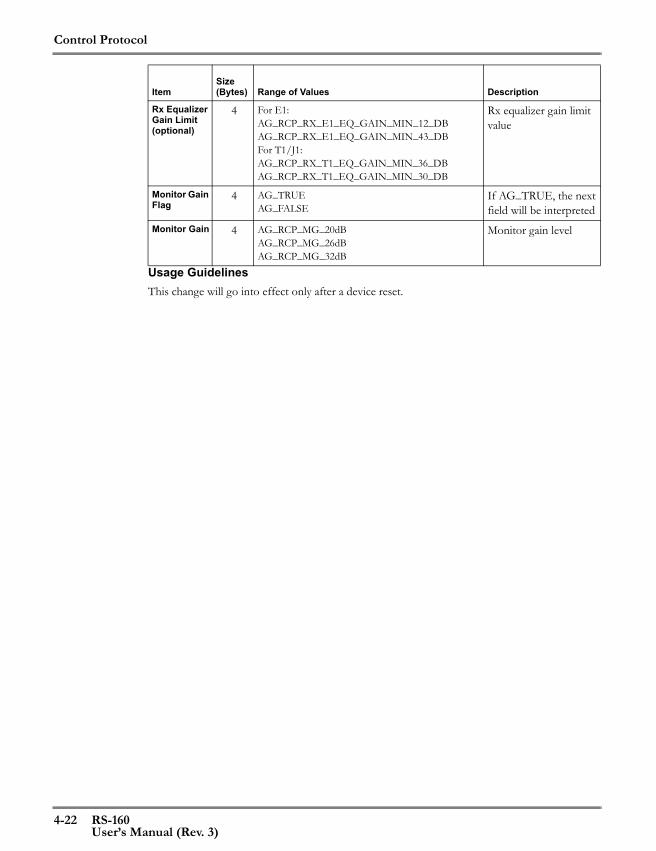
Control Protocol
4-22 RS-160User’s Manual (Rev. 3)
Usage GuidelinesThis change will go into effect only after a device reset.
Rx Equalizer Gain Limit (optional)
4 For E1:AG_RCP_RX_E1_EQ_GAIN_MIN_12_DBAG_RCP_RX_E1_EQ_GAIN_MIN_43_DBFor T1/J1:AG_RCP_RX_T1_EQ_GAIN_MIN_36_DBAG_RCP_RX_T1_EQ_GAIN_MIN_30_DB
Rx equalizer gain limit value
Monitor Gain Flag
4 AG_TRUEAG_FALSE
If AG_TRUE, the next field will be interpreted
Monitor Gain 4 AG_RCP_MG_20dBAG_RCP_MG_26dBAG_RCP_MG_32dB
Monitor gain level
ItemSize (Bytes) Range of Values Description

Control Protocol
RS-160 4-23User’s Manual (Rev. 3)
SetConfigLIULineCode
Usage GuidelinesThis change will go into effect only after a device reset.
ItemSize (Bytes) Range of Values Description
Message ID 2 AG_RCP_SET_CFG_LIU_LINE_CODE_MSG_ID
Message Type
2 AG_RCP_CALL
Message Length
2 8
Status 2 AG_RCP_ACK
Interface 4 AG_IF_A, AG_IF_B Interface to configureLine Code 4 For E1:
AG_RCP_LIU_LINE_CODE_E1_HDB3For T1/J1:AG_RCP_LIU_LINE_CODE_T1_B8ZSFor E1/T1/J1:AG_RCP_LIU_LINE_CODE_AMI
Line code
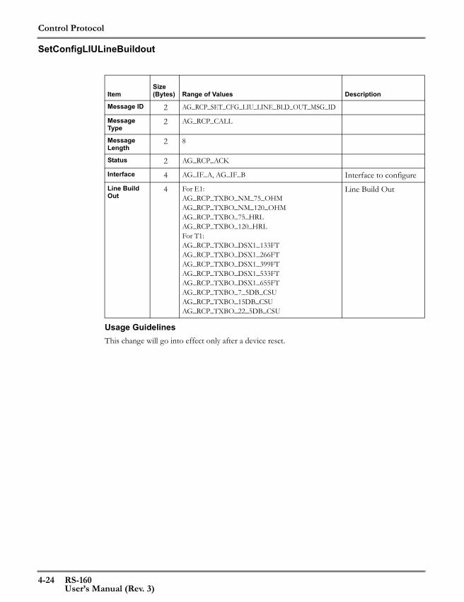
Control Protocol
4-24 RS-160User’s Manual (Rev. 3)
SetConfigLIULineBuildout
Usage GuidelinesThis change will go into effect only after a device reset.
ItemSize (Bytes) Range of Values Description
Message ID 2 AG_RCP_SET_CFG_LIU_LINE_BLD_OUT_MSG_ID
Message Type
2 AG_RCP_CALL
Message Length
2 8
Status 2 AG_RCP_ACK
Interface 4 AG_IF_A, AG_IF_B Interface to configureLine Build Out
4 For E1:AG_RCP_TXBO_NM_75_OHMAG_RCP_TXBO_NM_120_OHMAG_RCP_TXBO_75_HRLAG_RCP_TXBO_120_HRLFor T1:AG_RCP_TXBO_DSX1_133FTAG_RCP_TXBO_DSX1_266FTAG_RCP_TXBO_DSX1_399FTAG_RCP_TXBO_DSX1_533FTAG_RCP_TXBO_DSX1_655FTAG_RCP_TXBO_7_5DB_CSUAG_RCP_TXBO_15DB_CSUAG_RCP_TXBO_22_5DB_CSU
Line Build Out
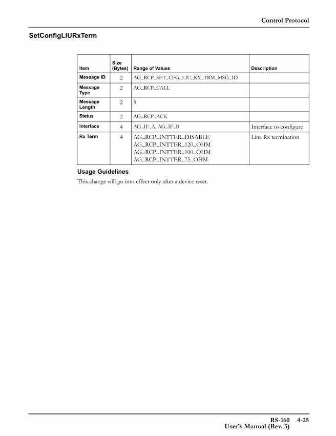
Control Protocol
RS-160 4-25User’s Manual (Rev. 3)
SetConfigLIURxTerm
Usage GuidelinesThis change will go into effect only after a device reset.
ItemSize (Bytes) Range of Values Description
Message ID 2 AG_RCP_SET_CFG_LIU_RX_TRM_MSG_ID
Message Type
2 AG_RCP_CALL
Message Length
2 8
Status 2 AG_RCP_ACK
Interface 4 AG_IF_A, AG_IF_B Interface to configureRx Term 4 AG_RCP_INTTER_DISABLE
AG_RCP_INTTER_120_OHMAG_RCP_INTTER_100_OHMAG_RCP_INTTER_75_OHM
Line Rx termination

Control Protocol
4-26 RS-160User’s Manual (Rev. 3)
SetConfigJitterAttenuation
Usage GuidelinesThis change will go into effect only after a device reset.
ItemSize (Bytes) Range of Values Description
Message ID 2 AG_RCP_SET_CFG_LIU_JITTER_MSG_ID
Message Type
2 AG_RCP_CALL
Message Length
2 8
Status 2 AG_RCP_ACK
Interface 4 AG_IF_AAG_IF_B
Interface to configure
Jitter Attenu-ator
4 AG_TRUEAG_FALSE
Enables/disables a LIU Tx jitter attenuator
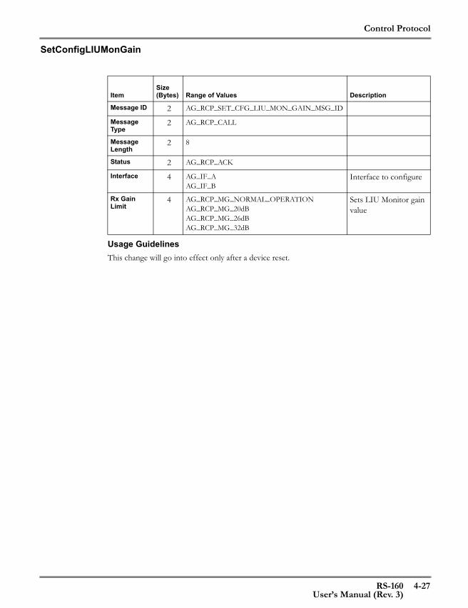
Control Protocol
RS-160 4-27User’s Manual (Rev. 3)
SetConfigLIUMonGain
Usage GuidelinesThis change will go into effect only after a device reset.
ItemSize (Bytes) Range of Values Description
Message ID 2 AG_RCP_SET_CFG_LIU_MON_GAIN_MSG_ID
Message Type
2 AG_RCP_CALL
Message Length
2 8
Status 2 AG_RCP_ACK
Interface 4 AG_IF_AAG_IF_B
Interface to configure
Rx Gain Limit
4 AG_RCP_MG_NORMAL_OPERATIONAG_RCP_MG_20dBAG_RCP_MG_26dBAG_RCP_MG_32dB
Sets LIU Monitor gain value

Control Protocol
4-28 RS-160User’s Manual (Rev. 3)
GetLIUStatus
Usage Guidelines
ItemSize (Bytes) Range of Values Description
Message ID 2 AG_RCP_GET_LIU_STATUS_MSG_ID
Message Type
2 AG_RCP_CALL
Message Length
2 4
Status 2 AG_RCP_ACK
Interface 4 AG_IF_BAG_IF_A
Interface for which information is desired

Control Protocol
RS-160 4-29User’s Manual (Rev. 3)
GetConfigLIU
Usage Guidelines
ItemSize (Bytes) Range of Values Description
Message ID 2 AG_RCP_GET_CFG_LIU_MSG_ID
Message Type
2 AG_RCP_CALL
Message Length
2 4
Status 2 AG_RCP_ACK
Interface 4 AG_IF_BAG_IF_A
Interface for which information is desired
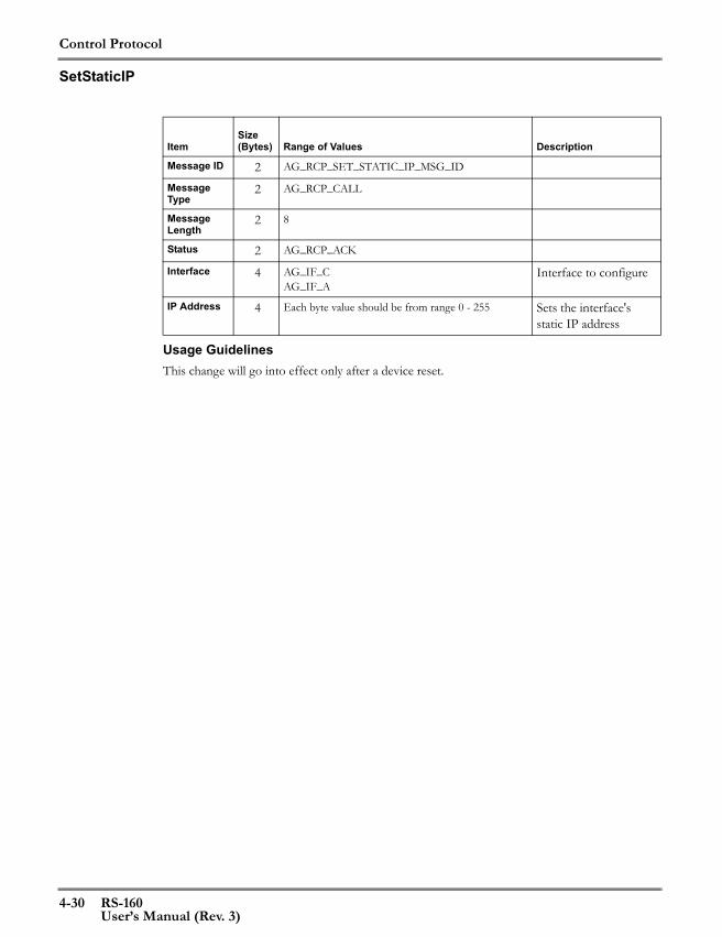
Control Protocol
4-30 RS-160User’s Manual (Rev. 3)
SetStaticIP
Usage GuidelinesThis change will go into effect only after a device reset.
ItemSize (Bytes) Range of Values Description
Message ID 2 AG_RCP_SET_STATIC_IP_MSG_ID
Message Type
2 AG_RCP_CALL
Message Length
2 8
Status 2 AG_RCP_ACK
Interface 4 AG_IF_CAG_IF_A
Interface to configure
IP Address 4 Each byte value should be from range 0 - 255 Sets the interface's static IP address

Control Protocol
RS-160 4-31User’s Manual (Rev. 3)
GetStaticIPCfg
Usage Guidelines
ItemSize (Bytes) Range of Values Description
Message ID 2 AG_RCP_GET_STATIC_IP_MSG_ID
Message Type
2 AG_RCP_CALL
Message Length
2 4
Status 2 AG_RCP_ACK
Interface 4 AG_IF_CAG_IF_A
Interface for which information is desired

Control Protocol
4-32 RS-160User’s Manual (Rev. 3)
SetSubNetMask
Usage GuidelinesThis change will go into effect only after a device reset.
ItemSize (Bytes) Range of Values Description
Message ID 2 AG_RCP_SET_SUB_NET_MASK_MSG_ID
Message Type
2 AG_RCP_CALL
Message Length
2 8
Status 2 AG_RCP_ACK
Interface 4 AG_IF_C,AG_IF_A
Interface to configure
Subnet Mask 4 Each byte value should be from range 0 - 255 Sets the interface's sub-net mask

Control Protocol
RS-160 4-33User’s Manual (Rev. 3)
GetConfig
Usage GuidelinesThis function requests the current configuration of the CES application. See page 3-24 for anexample of the CES application GetConfig report. See page 4-63 for the GetConfig responsemessage.
ItemSize (Bytes) Range of Values Description
Message ID 2 AG_RCP_GET_CFG_CES_APP_MSG_ID
Message Type
2 AG_RCP_CALL
Message Length
2 4
Status 2 AG_RCP_ACK
Interface 4 AG_IF_AAG_IF_B
Subscriber interface

Control Protocol
4-34 RS-160User’s Manual (Rev. 3)
GetStatusCesApp
Usage GuidelinesThis function requests the status of the CES application. See page 3-24 for an example of the CESapplication GetConfig report. See page 4-63 for the GetConfig response message.
ItemSize (Bytes) Range of Values Description
Message ID 2 AG_RCP_GET_STATUS_CES_APP_MSG_ID
Message Type
2 AG_RCP_CALL
Message Length
2 4
Status 2 AG_RCP_ACK
Interface 4 AG_IF_AAG_IF_B
Subscriber interface

Control Protocol
RS-160 4-35User’s Manual (Rev. 3)
ResetCesStatus
Usage GuidelinesThis function resets CES status information - the varying numeric parameters that are reported inthe GetStatusCesApp response message are set to zero.
ItemSize (Bytes) Range of Values Description
Message ID 2 AG_RCP_RESET_CES_STATUS_MSG_ID
Message Type
2 AG_RCP_CALL
Message Length
2 4
Status 2 AG_RCP_ACK
Interface 4 AG_IF_AAG_IF_B
Subscriber interface
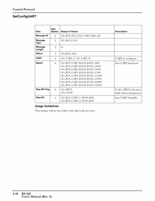
Control Protocol
4-36 RS-160User’s Manual (Rev. 3)
SetConfigUART
Usage GuidelinesThis change will go into effect only after a device reset.
ItemSize (Bytes) Range of Values Description
Message ID 2 AG_RCP_SET_CFG_UART_MSG_ID
Message Type
2 AG_RCP_CALL
Message Length
2 16
Status 2 AG_RCP_ACK
UART 4 AG_UART_A, AG_UART_B UART to configureSpeed 4 AG_RCP_UART_BAUD_RATE_9600
AG_RCP_UART_BAUD_RATE_19200AG_RCP_UART_BAUD_RATE_38400AG_RCP_UART_BAUD_RATE_57600AG_RCP_UART_BAUD_RATE_115200AG_RCP_UART_BAUD_RATE_230400AG_RCP_UART_BAUD_RATE_460800AG_RCP_UART_BAUD_RATE_921600
Sets UART baud rate
Stop Bit Flag 4 AG_TRUEAG_FALSE
If AG_TRUE, the next field will be interpreted
Stop Bit 4 AG_RCP_UART_1_STOP_BITSAG_RCP_UART_2_STOP_BITS
Sets UART Stop Bit

Control Protocol
RS-160 4-37User’s Manual (Rev. 3)
SetConfigUARTApp
Usage GuidelinesThis change will go into effect only after a device reset.
ItemSize (Bytes) Range of Values Description
Message ID 2 AG_RCP_SET_CFG_UART_APP_MSG_ID
Message Type
2 AG_RCP_CALL
Message Length
2 8
Status 2 AG_RCP_ACK
UART 4 AG_UART_A, AG_UART_B UART to configureApplication Mode
4 AG_RCP_UART_USAGE_PPPAG_RCP_UART_USAGE_LDPAG_RCP_UART_USAGE_TERMINALAG_RCP_UART_USAGE_MESSAGEAG_RCP_UART_USAGE_TRACEAG_RCP_UART_USAGE_RS_MASTERAG_RCP_UART_USAGE_RS_SLAVEAG_RCP_UART_USAGE_TDM
Sets UART application mode
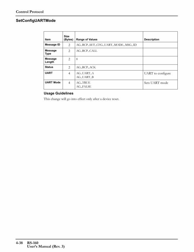
Control Protocol
4-38 RS-160User’s Manual (Rev. 3)
SetConfigUARTMode
Usage GuidelinesThis change will go into effect only after a device reset.
ItemSize (Bytes) Range of Values Description
Message ID 2 AG_RCP_SET_CFG_UART_MODE_MSG_ID
Message Type
2 AG_RCP_CALL
Message Length
2 8
Status 2 AG_RCP_ACK
UART 4 AG_UART_AAG_UART_B
UART to configure
UART Mode 4 AG_TRUEAG_FALSE
Sets UART mode

Control Protocol
RS-160 4-39User’s Manual (Rev. 3)
GetConfigUART
Usage Guidelines
ItemSize (Bytes) Range of Values Description
Message ID 2 AG_RCP_GET_CFG_UART_MSG_ID
Message Type
2 AG_RCP_CALL
Message Length
2 4
Status 2 AG_RCP_ACK
UART 4 AG_UART_A AG_UART_B
Interface for which information is desired

Control Protocol
4-40 RS-160User’s Manual (Rev. 3)
GetVersion
Usage Guidelines
ItemSize (Bytes) Range of Values Description
Message ID 2 AG_RCP_GEN_GET_VERSION_MSG_ID
Message Type
2 AG_RCP_CALL
Message Length
2 0
Status 2 AG_RCP_ACK
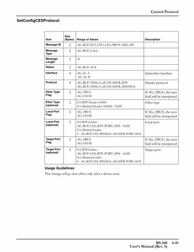
Control Protocol
RS-160 4-41User’s Manual (Rev. 3)
SetConfigCESProtocol
Usage GuidelinesThis change will go into effect only after a device reset.
ItemSize (Bytes) Range of Values Description
Message ID 2 AG_RCP_SET_CFG_CES_PROT_MSG_ID
Message Type
2 AG_RCP_CALL
Message Length
2 20
Status 2 AG_RCP_ACK
Interface 4 AG_IF_A AG_IF_B
Subscriber interface
Protocol 4 AG_RCP_TDM_O_IP_HEADER_RTP AG_RCP_TDM_O_IP_HEADER_MINIMAL
Header protocol
Ether Type Flag
2 AG_TRUEAG_FALSE
If AG_TRUE, the next field will be interpreted
Ether Type (optional)
2 For RTP Header: 0x800For Minimal Header: 0x0600 - 0xffff
Ether type
Local Port Flag
2 AG_TRUEAG_FALSE
If AG_TRUE, the next field will be interpreted
Local Port (optional)
2 For RTP header:AG_RCP_CES_RTP_PORT_MIN - 0xffffFor Minimal header:0 - AG_RCP_CES_MINIMAL_HEADER_PORT_MAX
Local port
Target Port Flag
2 AG_TRUEAG_FALSE
If AG_TRUE, the next field will be interpreted
Target Port (optional)
2 For RTP header:AG_RCP_CES_RTP_PORT_MIN - 0xffffFor Minimal header:0 - AG_RCP_CES_MINIMAL_HEADER_PORT_MAX
Target port
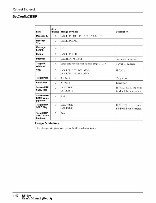
Control Protocol
4-42 RS-160User’s Manual (Rev. 3)
SetConfigCESIP
Usage GuidelinesThis change will go into effect only after a device reset.
ItemSize (Bytes) Range of Values Description
Message ID 2 AG_RCP_SET_CFG_CES_IP_MSG_ID
Message Type
2 AG_RCP_CALL
Message Length
2 22
Status 2 AG_RCP_ACK
Interface 4 AG_IF_A, AG_IF_B Subscriber interfaceTarget IP Address
4 Each byte value should be from range 0 - 255 Target IP address
TOS 2 AG_RCP_CES_TOS_MIN - AG_RCP_CES_TOS_MAX
IP TOS
Target Port 2 0 - 0xffff Target portLocal Port 2 0 - 0xffff Local portSource RTP SSRC Flag
2 AG_TRUEAG_FALSE
If AG_TRUE, the next field will be interpreted
Source RTP SSRC Value (optional)
2 NA
Target RTP SSRC Flag
2 AG_TRUEAG_FALSE
If AG_TRUE, the next field will be interpreted
Target RTP SSRC Value (optional)
2 NA

Control Protocol
RS-160 4-43User’s Manual (Rev. 3)
SetConfigCESPayLength
Usage GuidelinesThis change will go into effect only after a device reset.
ItemSize (Bytes) Range of Values Description
Message ID 2 AG_RCP_SET_CFG_CES_PAYLD_LEN_MSG_ID
Message Type
2 AG_RCP_CALL
Message Length
2 6
Status 2 AG_RCP_ACK
Interface 4 AG_IF_AAG_IF_B
Subscriber interface
Payload Length
2 AG _RCP_CES_PAYLOAD_LEN_MIN - AG_RCP_CES_PAYLOAD_LEN_MAX
Payload Length in bytes

Control Protocol
4-44 RS-160User’s Manual (Rev. 3)
SetConfigCESClock
Usage GuidelinesThis change will go into effect only after a device reset.
ItemSize (Bytes) Range of Values Description
Message ID 2 AG_RCP_SET_CFG_CES_CLK_MSG_ID
Message Type
2 AG_RCP_CALL
Message Length
2 10
Status 2 AG_RCP_ACK
Interface 4 AG_IF_AAG_IF_B
Subscriber interface
Max Jitter Delay
2 AG _RCP_CES_MAX_JITTER_MIN - AG _RCP_CES_MAX_JITTER_MAX
Maximum jitter delay (milliseconds)
Reserved Jit-ter Delay
2 AG _RCP_CES_JITTER_MIN_RESERVE_MIN - AG_RCP_CES_JITTER_MIN_RESERVE_MAX
Minimum jitter delay (percentage)
Reserved 2
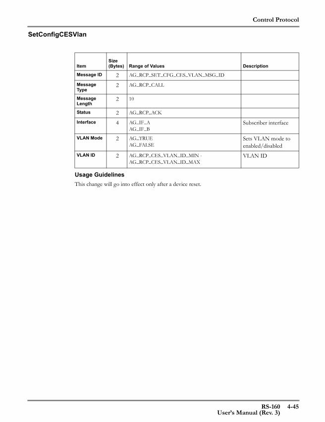
Control Protocol
RS-160 4-45User’s Manual (Rev. 3)
SetConfigCESVlan
Usage GuidelinesThis change will go into effect only after a device reset.
ItemSize (Bytes) Range of Values Description
Message ID 2 AG_RCP_SET_CFG_CES_VLAN_MSG_ID
Message Type
2 AG_RCP_CALL
Message Length
2 10
Status 2 AG_RCP_ACK
Interface 4 AG_IF_AAG_IF_B
Subscriber interface
VLAN Mode 2 AG_TRUEAG_FALSE
Sets VLAN mode to enabled/disabled
VLAN ID 2 AG_RCP_CES_VLAN_ID_MIN - AG_RCP_CES_VLAN_ID_MAX
VLAN ID
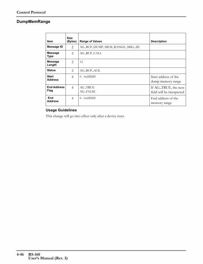
Control Protocol
4-46 RS-160User’s Manual (Rev. 3)
DumpMemRange
Usage GuidelinesThis change will go into effect only after a device reset.
ItemSize (Bytes) Range of Values Description
Message ID 2 AG_RCP_DUMP_MEM_RANGE_MSG_ID
Message Type
2 AG_RCP_CALL
Message Length
2 12
Status 2 AG_RCP_ACK
Start Address
4 0 - 0xffffffff Start address of the dump memory range
End Address Flag
4 AG_TRUEAG_FALSE
If AG_TRUE, the next field will be interpreted
End Address
4 0 - 0xffffffff End address of the memory range

Control Protocol
RS-160 4-47User’s Manual (Rev. 3)
DumpMemLength
Usage GuidelinesThis change will go into effect only after a device reset.
ItemSize (Bytes) Range of Values Description
Message ID 2 AG_RCP_DUMP_MEM_LEN_MSG_ID
Message Type
2 AG_RCP_CALL
Message Length
2 12
Status 2 AG_RCP_ACK
Address 4 0 - 0xffffffff Start address of the dump memory range
Length Flag 4 AG_TRUEAG_FALSE
If AG_TRUE, the next field will be interpreted
Length (optional)
4 1 - AG_RCP_RW_MEM_MAX_SIZE_IN_BYTES Number of bytes to dump
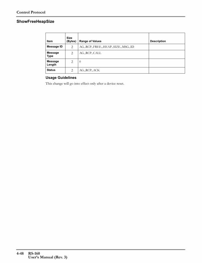
Control Protocol
4-48 RS-160User’s Manual (Rev. 3)
ShowFreeHeapSize
Usage GuidelinesThis change will go into effect only after a device reset.
ItemSize (Bytes) Range of Values Description
Message ID 2 AG_RCP_FREE_HEAP_SIZE_MSG_ID
Message Type
2 AG_RCP_CALL
Message Length
2 0
Status 2 AG_RCP_ACK
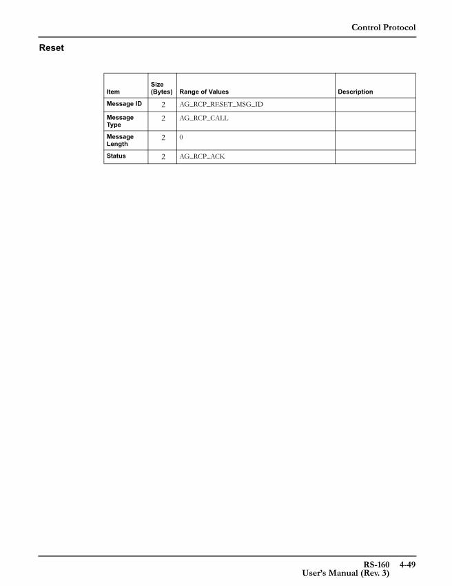
Control Protocol
RS-160 4-49User’s Manual (Rev. 3)
Reset
ItemSize (Bytes) Range of Values Description
Message ID 2 AG_RCP_RESET_MSG_ID
Message Type
2 AG_RCP_CALL
Message Length
2 0
Status 2 AG_RCP_ACK
Control Protocol
4-50 RS-160User’s Manual (Rev. 3)
Response Message DescriptionsThe following pages contain descriptions of each response message.
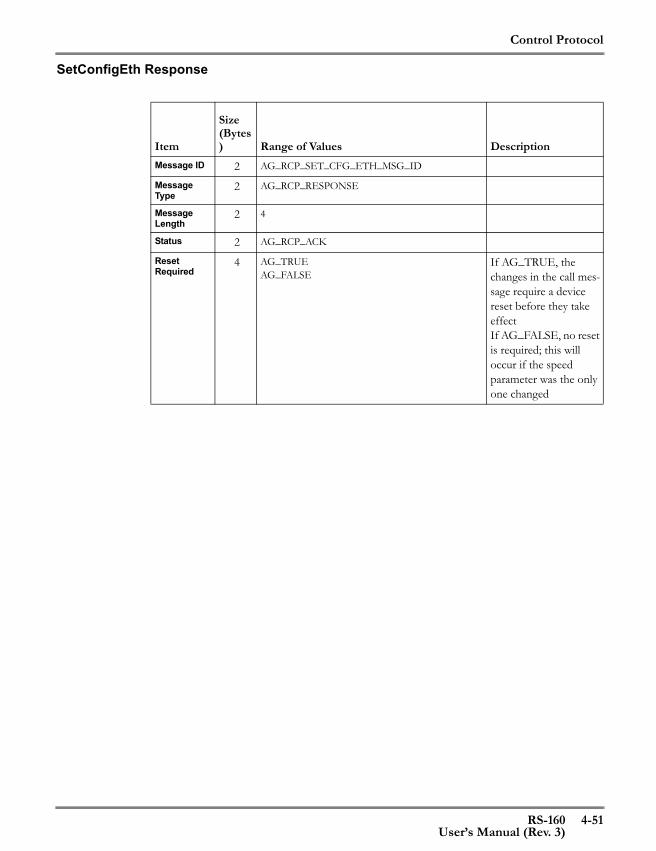
Control Protocol
RS-160 4-51User’s Manual (Rev. 3)
SetConfigEth Response
Item
Size (Bytes) Range of Values Description
Message ID 2 AG_RCP_SET_CFG_ETH_MSG_ID
Message Type
2 AG_RCP_RESPONSE
Message Length
2 4
Status 2 AG_RCP_ACK
Reset Required
4 AG_TRUEAG_FALSE
If AG_TRUE, the changes in the call mes-sage require a device reset before they take effectIf AG_FALSE, no reset is required; this will occur if the speed parameter was the only one changed

Control Protocol
4-52 RS-160User’s Manual (Rev. 3)
GetEthStatus Response
ItemSize
(Bytes) Range of Values DescriptionMessage ID 2 AG_RCP_GET_ETH_STATUS_MSG_ID
Message Type
2 AG_RCP_CALL
Message Length
2 60
Status 2 AG_RCP_ RESPONSE
Link State Flag
4 AG_TRUEAG_FALSE
Link State 4 AG_RCP_IF_UNKNOWN_STATEAG_RCP_IF_LINK_UP,AG_RCP_IF_LINK_DOWN
PHY State Flag
4 AG_TRUEAG_FALSE
PHY State Reset
4 AG_TRUEAG_FALSE
Auto Negoti-ation Flag
4 AG_TRUEAG_FALSE
Auto Negoti-ation
4 AG_TRUEAG_FALSE
Peer Adver-tisement Value Flag
4 AG_TRUEAG_FALSE
Peer Adver-tisement Value
4
Current Speed Flag
4 AG_TRUEAG_FALSE
Current Speed
4 AG_RCP_IF_SPEED_UNKNOWNAG_RCP_IF_SPEED_10AG_RCP_IF_SPEED_100
Current Duplex Mode Flag
4 AG_TRUEAG_FALSE
Current Duplex Mode
4 AG_RCP_IF_DUP_UNKNOWNAG_RCP_IF_DUP_HALFAG_RCP_IF_DUP_FULL
Current Flow Control Flag
4 AG_TRUEAG_FALSE
Current Flow Control
4 AG_RCP_IF_FC_UNKNOWNAG_RCP_IF_FC_ONAG_RCP_IF_FC_OFF
MAC Loop-back
4 AG_TRUEAG_FALSE
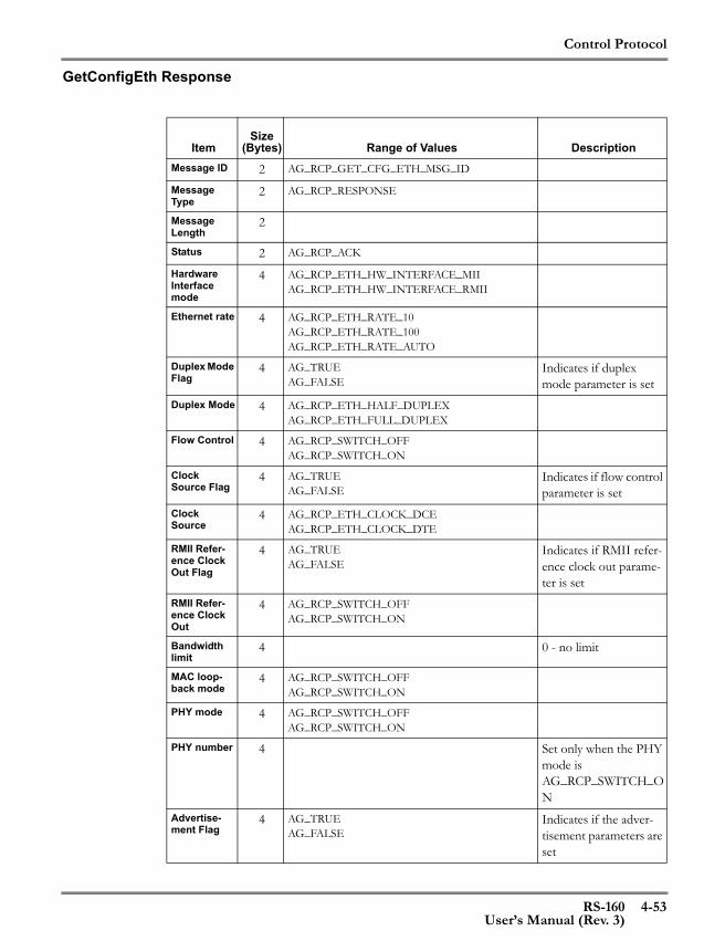
Control Protocol
RS-160 4-53User’s Manual (Rev. 3)
GetConfigEth Response
ItemSize
(Bytes) Range of Values DescriptionMessage ID 2 AG_RCP_GET_CFG_ETH_MSG_ID
Message Type
2 AG_RCP_RESPONSE
Message Length
2
Status 2 AG_RCP_ACK
Hardware Interface mode
4 AG_RCP_ETH_HW_INTERFACE_MIIAG_RCP_ETH_HW_INTERFACE_RMII
Ethernet rate 4 AG_RCP_ETH_RATE_10AG_RCP_ETH_RATE_100AG_RCP_ETH_RATE_AUTO
Duplex Mode Flag
4 AG_TRUEAG_FALSE
Indicates if duplex mode parameter is set
Duplex Mode 4 AG_RCP_ETH_HALF_DUPLEXAG_RCP_ETH_FULL_DUPLEX
Flow Control 4 AG_RCP_SWITCH_OFFAG_RCP_SWITCH_ON
Clock Source Flag
4 AG_TRUEAG_FALSE
Indicates if flow control parameter is set
Clock Source
4 AG_RCP_ETH_CLOCK_DCEAG_RCP_ETH_CLOCK_DTE
RMII Refer-ence Clock Out Flag
4 AG_TRUEAG_FALSE
Indicates if RMII refer-ence clock out parame-ter is set
RMII Refer-ence Clock Out
4 AG_RCP_SWITCH_OFFAG_RCP_SWITCH_ON
Bandwidth limit
4 0 - no limit
MAC loop-back mode
4 AG_RCP_SWITCH_OFFAG_RCP_SWITCH_ON
PHY mode 4 AG_RCP_SWITCH_OFFAG_RCP_SWITCH_ON
PHY number 4 Set only when the PHY mode is AG_RCP_SWITCH_ON
Advertise-ment Flag
4 AG_TRUEAG_FALSE
Indicates if the adver-tisement parameters are set

Control Protocol
4-54 RS-160User’s Manual (Rev. 3)
Advertise-ment Speed: 10Duplex Mode: Half
4 AG_TRUEAG_FALSE
Advertise-ment Speed: 10Duplex Mode: Full
4 AG_TRUEAG_FALSE
Advertise-ment Speed: 100Duplex Mode: Half
4 AG_TRUEAG_FALSE
Advertise-ment Speed: 100Duplex Mode: Full
4 AG_TRUEAG_FALSE
MAC Address
6 Array of bytes
ItemSize
(Bytes) Range of Values Description

Control Protocol
RS-160 4-55User’s Manual (Rev. 3)
GetBitStreamStatus Response
ItemSize
(Bytes) Range of Values DescriptionMessage ID 2 AG_RCP_GET_BS_STATUS_MSG_ID
Message Type
2 AG_RCP_RESPONSE
Message Length
2 16
Status 2 AG_RCP_ACK
Link State 4 AG_RCP_IF_UNKNOWN_STATEAG_RCP_IF_LINK_UPAG_RCP_IF_LINK_DOWN
AIS Alarm 4 AG_TRUEAG_FALSE
LOS Alarm 4 AG_TRUEAG_FALSE
Bit Stream Loopback State
4 AG_RCP_BS_LOOPBACK_DISABLEDAG_RCP_BS_LOOPBACK_EXIST_WITH_TXAG_RCP_BS_LOOPBACK_EXISTAG_RCP_BS_LOOPBACK_REMOTE_WITH_RXAG_RCP_BS_LOOPBACK_REMOTEAG_RCP_BS_LOOPBACK_DUAL

Control Protocol
4-56 RS-160User’s Manual (Rev. 3)
GetConfigBitStream Response
ItemSize
(Bytes) Range of Values DescriptionMessage ID 2 AG_RCP_GET_CFG_BS_MSG_ID
Message Type
2 AG_RCP_RESPONSE
Message Length
2 24
Status 2 AG_RCP_ACK
Frame Size 4Under Run Value
4
Clock Source
4 AG_RCP_WAN_CLOCK_INPUT_MODEAG_RCP_WAN_CLOCK_OUTPUT_MODEAG_RCP_WAN_CLOCK_RECOVERY_MODEAG_RCP_WAN_CLOCK_LPBK_MODE
Tx Clock Polarity
4 AG_RCP_TX_CLOCK_FALLINGAG_RCP_TX_CLOCK_RISING
Rx Clock Polarity
4 AG_RCP_RX_CLOCK_RISING AG_RCP_RX_CLOCK_FALLING
Loopback 4 AG_RCP_BS_LOOPBACK_DISABLED AG_RCP_BS_LOOPBACK_EXIST_WITH_TXAG_RCP_BS_LOOPBACK_EXISTAG_RCP_BS_LOOPBACK_REMOTE_WITH_RXAG_RCP_BS_LOOPBACK_REMOTEAG_RCP_BS_LOOPBACK_DUAL
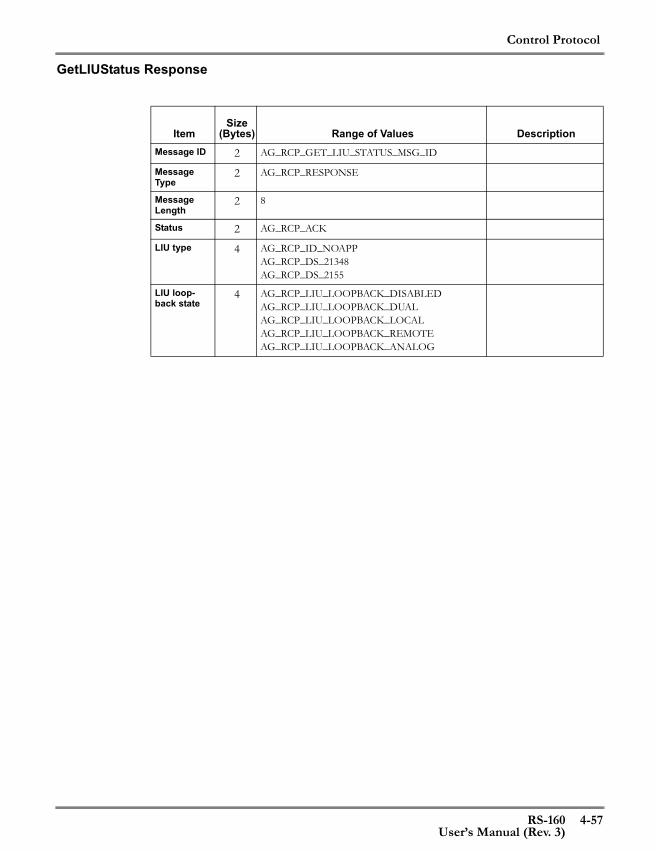
Control Protocol
RS-160 4-57User’s Manual (Rev. 3)
GetLIUStatus Response
ItemSize
(Bytes) Range of Values DescriptionMessage ID 2 AG_RCP_GET_LIU_STATUS_MSG_ID
Message Type
2 AG_RCP_RESPONSE
Message Length
2 8
Status 2 AG_RCP_ACK
LIU type 4 AG_RCP_ID_NOAPPAG_RCP_DS_21348AG_RCP_DS_2155
LIU loop-back state
4 AG_RCP_LIU_LOOPBACK_DISABLED AG_RCP_LIU_LOOPBACK_DUALAG_RCP_LIU_LOOPBACK_LOCALAG_RCP_LIU_LOOPBACK_REMOTEAG_RCP_LIU_LOOPBACK_ANALOG

Control Protocol
4-58 RS-160User’s Manual (Rev. 3)
GetConfigLIU Response
ItemSize
(Bytes) Range of Values DescriptionMessage ID 2 AG_RCP_GET_CFG_LIU_MSG_ID
Message Type
2 AG_RCP_RESPONSE
Message Length
2
Status 2 AG_RCP_ACK
Line Format Flag
4 AG_TRUEAG_FALSE
Indicates if Line Format parameter is set
Line Format 4 AG_RCP_BITSTREAM_MODE_E1AG_RCP_BITSTREAM_MODE_T1AG_RCP_BITSTREAM_MODE_J1
LIU type 4 AG_RCP_ID_NOAPPAG_RCP_DS_21348AG_RCP_DS_2155
Line Code Flag
4 AG_TRUEAG_FALSE
Indicates if Line Code parameter is set
Line Code 4 For E1:AG_RCP_LIU_LINE_CODE_E1_HDB3AG_RCP_LIU_LINE_CODE_AMI For T1/J1:AG_RCP_LIU_LINE_CODE_T1_B8ZS AG_RCP_LIU_LINE_CODE_AMI
Line Build Out Flag
4 AG_TRUE AG_FALSE
Indicates if Line Build Out parameter is set
Line Build Out
4 E1 line termination values: AG_RCP_TXBO_NM_75_OHM = 0, AG_RCP_TXBO_NM_120_OHM= 1AG_RCP_TXBO_75_HRL = 4AG_RCP_TXBO_120_HRL= 5T1/J1 line termination values: AG_RCP_TXBO_DSX1_133FT = 0AG_RCP_TXBO_DSX1_266FT= 1AG_RCP_TXBO_DSX1_399FT= 2AG_RCP_TXBO_DSX1_533FT= 3AG_RCP_TXBO_DSX1_655FT= 4AG_RCP_TXBO_7_5DB_CSU= 5AG_RCP_TXBO_15DB_CSU= 6AG_RCP_TXBO_22_5DB_CSU= 7
Rx termina-tion Flag
4 AG_TRUEAG_FALSE
Indicates if Rx Termi-nation parameter is set
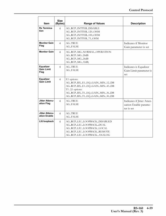
Control Protocol
RS-160 4-59User’s Manual (Rev. 3)
Rx Termina-tion
4 AG_RCP_INTTER_DISABLEAG_RCP_INTTER_120_OHMAG_RCP_INTTER_100_OHMAG_RCP_INTTER_75_OHM
Monitor Gain Flag
4 AG_TRUEAG_FALSE
Indicates if Monitor Gain parameter is set
Monitor Gain 4 AG_RCP_MG_NORMAL_OPERATIONAG_RCP_MG_20dBAG_RCP_MG_26dBAG_RCP_MG_32dB,
Equalizer Gain Limit Flag
4 AG_TRUEAG_FALSE
Indicates is Equalizer Gain Limit parameter is set
Equalizer Gain Limit
4 E1 options:AG_RCP_RX_E1_EQ_GAIN_MIN_12_DBAG_RCP_RX_E1_EQ_GAIN_MIN_43_DBT1 /J1 options:AG_RCP_RX_T1_EQ_GAIN_MIN_36_DB AG_RCP_RX_T1_EQ_GAIN_MIN_30_DB
Jitter Attenu-ation Flag
4 AG_TRUEAG_FALSE
Indicates if Jitter Atten-uation Enable parame-ter is set
Jitter Attenu-ation Enable
4 AG_TRUEAG_FALSE
LIU loopback 4 AG_RCP_LIU_LOOPBACK_DISABLEDAG_RCP_LIU_LOOPBACK_DUALAG_RCP_LIU_LOOPBACK_LOCALAG_RCP_LIU_LOOPBACK_REMOTEAG_RCP_LIU_LOOPBACK_ANALOG
ItemSize
(Bytes) Range of Values Description

Control Protocol
4-60 RS-160User’s Manual (Rev. 3)
GetStaticIPCfg Response
ItemSize (Bytes) Range of Values Description
Message ID 2 AG_RCP_GET_STATIC_IP_MSG_ID
Message Type
2 AG_RCP_RESPONSE
Message Length
2 12
Status 2 AG_RCP_ACK
Interface 4 AG_IF_CAG_IF_A
Interface for which information is desired
IP Address 4 IP address for the selected interface
IP Subnet Mask
4 IP subnet mask for the selected interface
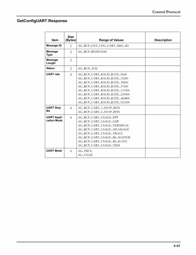
Control Protocol
4-61
GetConfigUART Response
ItemSize
(Bytes) Range of Values DescriptionMessage ID 2 AG_RCP_GET_CFG_UART_MSG_ID
Message Type
2 AG_RCP_RESPONSE
Message Length
2
Status 2 AG_RCP_ACK
UART rate 4 AG_RCP_UART_BAUD_RATE_9600AG_RCP_UART_BAUD_RATE_19200AG_RCP_UART_BAUD_RATE_38400AG_RCP_UART_BAUD_RATE_57600AG_RCP_UART_BAUD_RATE_115200AG_RCP_UART_BAUD_RATE_230400AG_RCP_UART_BAUD_RATE_460800AG_RCP_UART_BAUD_RATE_921600
UART Stop Bit
4 AG_RCP_UART_1_STOP_BITSAG_RCP_UART_2_STOP_BITS
UART Appli-cation Mode
4 AG_RCP_UART_USAGE_PPPAG_RCP_UART_USAGE_LDPAG_RCP_UART_USAGE_TERMINALAG_RCP_UART_USAGE_MEASSAGEAG_RCP_UART_USAGE_TRACEAG_RCP_UART_USAGE_RS_MASTERAG_RCP_UART_USAGE_RS_SLAVEAG_RCP_UART_USAGE_TDM
UART Mode 4 AG_TRUEAG_FALSE

Control Protocol
4-62
GetVersion Response
ItemSize (Bytes) Range of Values Description
Message ID 2 AG_RCP_GEN_GET_VERSION_MSG_ID
Message Type
2 AG_RCP_RESPONSE
Message Length
2 AG_RCP_VERSION_STR_SIZE + 4
Status 2 AG_RCP_ACK
Version Length
4 0 to AG_RCP_VERSION_STR_SIZE Length of the version string
Version AG_RCP_VERSION_STR_SIZE Product version

Control Protocol
4-63
GetConfig Response
ItemSize (Bytes) Range of Values Description
Message ID 2 AG_RCP_GET_CFG_CES_APP_MSG_ID
Message Type
2 AG_RCP_RESPONSE
Message Length
2 38
Status 2 AG_RCP_ACK
Protocol 4 AG_RCP_TDM_O_IP_HEADER_RTP or AG_RCP_TDM_O_IP_HEADER_MINIMAL
Header protocol
IP Address 4 Target IP AddressSubscriber Interface
4 AG_IF_AAG_IF_B
Subscriber interface
Service Inter-face
4 AG_IF_CAG_IF_A
Service Interface
IP TOS 2 AG_RCP_CES_TOS_MIN - AG_RCP_CES_TOS_MAX
IP TOS
Target Port 2 For RTP header:AG_RCP_CES_RTP_PORT_MIN - 0xffffFor Minimal header:0 - AG_RCP_CES_MINIMAL_HEADER_PORT_MAX
Target port
Source Port 2 For RTP header:AG_RCP_CES_RTP_PORT_MIN - 0xffffFor Minimal header:0 - AG_RCP_CES_MINIMAL_HEADER_PORT_MAX
Source port
Ether Type 2 For RTP header: 0x800For Minimal header: 0x0600 - 0xffff
Ether type
Payload Length
2 AG_RCP_CES_PAYLOAD_LEN_MIN - AG_RCP_CES_PAYLOAD_LEN_MAX
Payload Length in bytes
Max Jitter Delay
2 AG_RCP_CES_MAX_JITTER_MIN - AG_RCP_CES_MAX_JITTER_MAX
Maximum jitter delay (milliseconds)
Reserved Jit-ter Delay
2 AG_RCP_CES_JITTER_MIN_RESERVE_MIN - AG_RCP_CES_JITTER_MIN_RESERVE_MAX
Minimum jitter delay (percentage)
Recovery Clock Accu-racy
2 AG_RCP_CES_RECOVERY_CLOCK_ACCURACY_MIN - AG_RCP_CES_RECOVERY_CLOCK_ACCURACY_MAX
Recovery Clock Accu-racy (PPM)
VLAN Mode 2 AG_TRUE, AG_FALSE Indicates whether VLAN mode is enabled/disabled
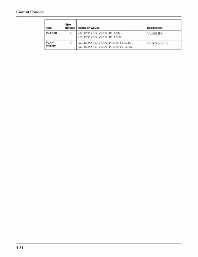
Control Protocol
4-64
VLAN ID 2 AG_RCP_CES_VLAN_ID_MIN - AG_RCP_CES_VLAN_ID_MAX
VLAN ID
VLAN Priority
2 AG_RCP_CES_VLAN_PRIORITY_MIN -AG_RCP_CES_VLAN_PRIORITY_MAX
VLAN priority
ItemSize (Bytes) Range of Values Description
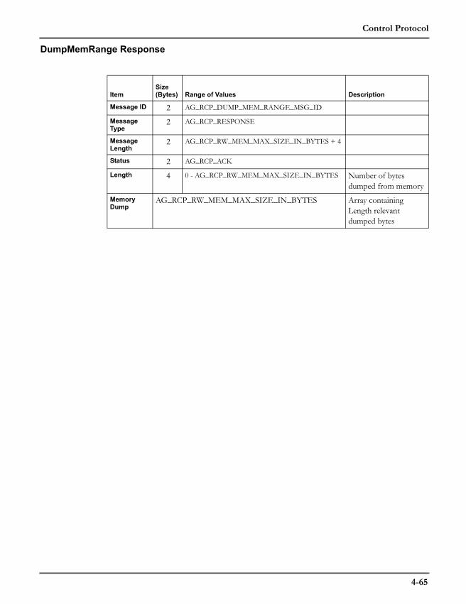
Control Protocol
4-65
DumpMemRange Response
ItemSize (Bytes) Range of Values Description
Message ID 2 AG_RCP_DUMP_MEM_RANGE_MSG_ID
Message Type
2 AG_RCP_RESPONSE
Message Length
2 AG_RCP_RW_MEM_MAX_SIZE_IN_BYTES + 4
Status 2 AG_RCP_ACK
Length 4 0 - AG_RCP_RW_MEM_MAX_SIZE_IN_BYTES Number of bytes dumped from memory
Memory Dump
AG_RCP_RW_MEM_MAX_SIZE_IN_BYTES Array containing Length relevant dumped bytes

Control Protocol
4-66
DumpMemLength Response
ItemSize (Bytes) Range of Values Description
Message ID 2 AG_RCP_DUMP_MEM_LEN_MSG_ID
Message Type
2 AG_RCP_RESPONSE
Message Length
2 AG_RCP_RW_MEM_MAX_SIZE_IN_BYTES + 4
Status 2 AG_RCP_ACK
Length 4 0 - AG_RCP_RW_MEM_MAX_SIZE_IN_BYTES Number of bytes dumped from memory
Memory Dump
AG_RCP_RW_MEM_MAX_SIZE_IN_BYTES Array containing Length relevant dumped bytes

Control Protocol
4-67
GetStatusCesApp Response
ItemSize (Bytes) Range of Values Description
Message ID 2 AG_RCP_GET_STATUS_CES_APP_MSG_ID
Message Type
2 AG_RCP_RESPONSE
Message Length
2
Status 2 AG_RCP_ACK
Jitter Level 4 Current jitter buffer level
Jitter Over-flow
4 Number of times the Jitter buffer exceeded MAX depth
Jitter Under-flow
4 number of times the Jit-ter buffer fell below MIN depth
Utilization bandwidth
4 current CES application configuration band-width utilization
Jitter MIN level
4 jitter minimum level since last ResetCesSta-tus
Jitter MAX level
4 jitter maximum level since last ResetCesSta-tus
Connectivity Status
4 AG_RCP_CONNCTIY_STATUS_UPAG_RCP_CONNCTIY_STATUS_DOWNAG_RCP_CONNCTIY_STATUS_MISCONAG_RCP_CONNCTIY_STATUS_FE_UNREACHAG_RCP_CONNCTIY_STATUS_FE_FAIL
CES Connectivity sta-tus
Tx Clock Source
4 AG_RCP_CLOCK_INPUT_MODEAG_RCP_CLOCK_OUTPUT_MODEAG_RCP_CLOCK_RECOVERY_MODEAG_RCP_CLOCK_LPBK_MODE
Transmit Clock Source
Is Reach-able Flag
4 AG_TRUEAG_FALSE
target host ping reach-able (if AG_TRUE, - received response to ping)
Last ping trip ms time
4 target host last ping round trip time in msec
MAC Address
6 MAC Address of target
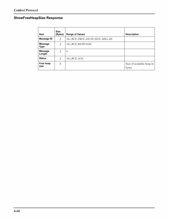
Control Protocol
4-68
ShowFreeHeapSize Response
ItemSize (Bytes) Range of Values Description
Message ID 2 AG_RCP_FREE_HEAP_SIZE_MSG_ID
Message Type
2 AG_RCP_RESPONSE
Message Length
2 4
Status 2 AG_RCP_ACK
Free heap size
4 Size of available heap in bytes
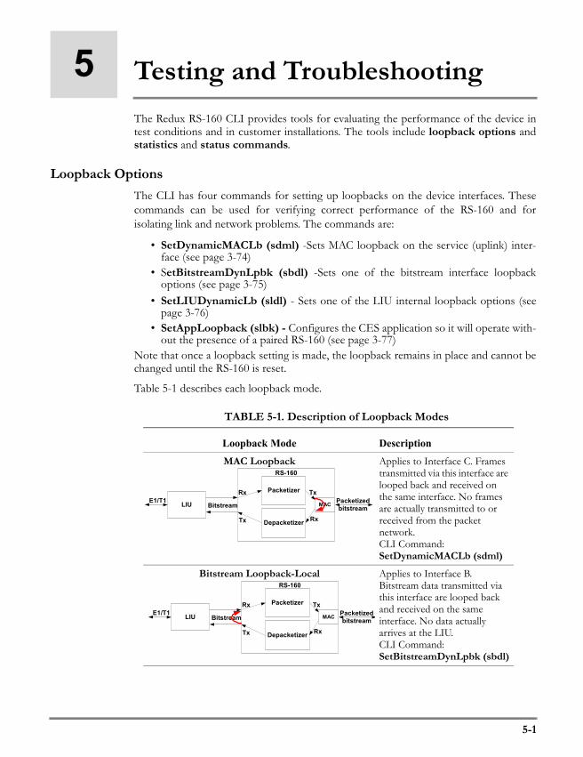
5-1
5 Testing and TroubleshootingThe Redux RS-160 CLI provides tools for evaluating the performance of the device intest conditions and in customer installations. The tools include loopback options andstatistics and status commands.
Loopback OptionsThe CLI has four commands for setting up loopbacks on the device interfaces. Thesecommands can be used for verifying correct performance of the RS-160 and forisolating link and network problems. The commands are:
• SetDynamicMACLb (sdml) -Sets MAC loopback on the service (uplink) inter-face (see page 3-74)
• SetBitstreamDynLpbk (sbdl) -Sets one of the bitstream interface loopbackoptions (see page 3-75)
• SetLIUDynamicLb (sldl) - Sets one of the LIU internal loopback options (seepage 3-76)
• SetAppLoopback (slbk) - Configures the CES application so it will operate with-out the presence of a paired RS-160 (see page 3-77)
Note that once a loopback setting is made, the loopback remains in place and cannot bechanged until the RS-160 is reset.
Table 5-1 describes each loopback mode.
TABLE 5-1. Description of Loopback Modes
Loopback Mode Description
MAC Loopback Applies to Interface C. Frames transmitted via this interface are looped back and received on the same interface. No frames are actually transmitted to or received from the packet network.CLI Command:SetDynamicMACLb (sdml)
Bitstream Loopback-Local Applies to Interface B. Bitstream data transmitted via this interface are looped back and received on the same interface. No data actually arrives at the LIU.CLI Command:SetBitstreamDynLpbk (sbdl)
LIU
Packetizer
Depacketizer
E1/T1Bitstream
Rx
Tx
Packetizedbitstream
Tx
RS-160
Rx
MAC
LIU
Packetizer
Depacketizer
E1/T1Bitstream
Rx
Tx
Packetizedbitstream
Tx
RS-160
Rx
MAC
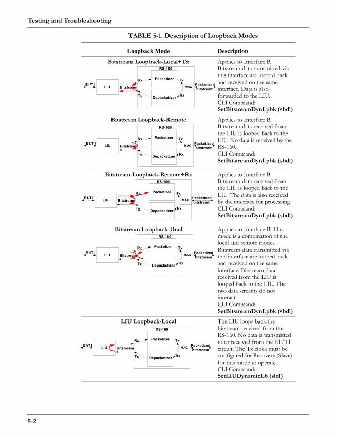
Testing and Troubleshooting
5-2
Bitstream Loopback-Local+Tx Applies to Interface B. Bitstream data transmitted via this interface are looped back and received on the same interface. Data is also forwarded to the LIU.CLI Command:SetBitstreamDynLpbk (sbdl)
Bitstream Loopback-Remote Applies to Interface B. Bitstream data received from the LIU is looped back to the LIU. No data is received by the RS-160.CLI Command:SetBitstreamDynLpbk (sbdl)
Bitstream Loopback-Remote+Rx Applies to Interface B. Bitstream data received from the LIU is looped back to the LIU. The data is also received by the interface for processing.CLI Command:SetBitstreamDynLpbk (sbdl)
Bitstream Loopback-Dual Applies to Interface B. This mode is a combination of the local and remote modes. Bitstream data transmitted via this interface are looped back and received on the same interface. Bitstream data received from the LIU is looped back to the LIU. The two data streams do not interact.CLI Command:SetBitstreamDynLpbk (sbdl)
LIU Loopback-Local The LIU loops back the bitstream received from the RS-160. No data is transmitted to or received from the E1/T1 circuit. The Tx clock must be configured for Recovery (Slave) for this mode to operate.CLI Command:SetLIUDynamicLb (sldl)
TABLE 5-1. Description of Loopback Modes
Loopback Mode Description
LIU
Packetizer
Depacketizer
E1/T1Bitstream
Rx
Tx
Packetizedbitstream
Tx
RS-160
Rx
MAC
LIU
Packetizer
Depacketizer
E1/T1Bitstream
Rx
Tx
Packetizedbitstream
Tx
RS-160
Rx
MAC
LIU
Packetizer
Depacketizer
E1/T1Bitstream
Rx
Tx
Packetizedbitstream
Tx
RS-160
Rx
MAC
LIU
Packetizer
Depacketizer
E1/T1Bitstream
Rx
Tx
Packetizedbitstream
Tx
RS-160
Rx
MAC
LIU
Packetizer
Depacketizer
E1/T1Bitstream
Rx
Tx
Packetizedbitstream
Tx
RS-160
Rx
MAC

Testing and Troubleshooting
5-3
The following example shows how the loopback settings can be used to verify operationof the RS-160 (Figure 5-1 shows the test setup):
Figure 5-1. Loopback Test Setup
Enter the following CLI commands:
\>m\i\c\Maint\Interfaces\Interface_C>sdml on
The request was updated successfully in active ConfigDB.
\Maint\Interfaces\Interface_C>\a\d\Admin\Debug>slbkThe command completed successfully.
LIU Loopback-Remote The LIU loops back the data stream received from the E1/T1 circuit. No data is transmitted to or received from the RS-160.CLI Command:SetLIUDynamicLb (sldl)
LIU Loopback-Dual This mode is a combination of the LIU local and remote modes. The LIU loops back the data stream received from the E1/T1 circuit. It also loops back the bitstream received from the RS-160. The two data streams do not interact. The Tx clock must be configured for Recovery (Slave) for this mode to operate.CLI Command:SetLIUDynamicLb (sldl)
TABLE 5-1. Description of Loopback Modes
Loopback Mode Description
LIU
Packetizer
Depacketizer
E1/T1Bitstream
Rx
Tx
Packetizedbitstream
Tx
RS-160
Rx
MAC
LIU
Packetizer
Depacketizer
E1/T1Bitstream
Rx
Tx
Packetizedbitstream
Tx
RS-160
Rx
MAC
LIU
Packetizer
Depacketizer
E1/T1Bitstream
Rx
Tx
Packetizedbitstream
Tx
RS-160
Rx
MAC
BTM orotherE1/T1
Test Unit

Testing and Troubleshooting
5-4
“sdml” sets up the MAC loopback, while “slbk” enables the RS-160 to transmit packetsto the uplink (service) interface without a paired RS-160 present. The user can now startan T1 or E1 data flow on the test unit and evaluate the looped back response.
Using the Get Status Command to Evaluate PerformanceThe CES application GetStatus CLI command reports on the status of the performanceof the RS-160. The following is a sample output of the command:
\View\App\CES>\v\a\ces\gs b Item Value/Status
Clock source....................: Loopback-master Connectivity....................: UP Current Jitter Buffer Delay (ms): 4.970 Jitter Overflow.................: 0 Jitter Underflow................: 01 Bandwidth Utilization(kbps).....: 2476 Jitter minimum level (ms).......: 4.970 Jitter maximum level (ms).......: 5.467 Peer reachable..................: YES Peer MAC address................: 01 84 C8 91 42 60 Peer ping time (ms).............: 7
The key parameters are those related to the jitter performance, which are described inTable 5-2..
The ResetStatistics command clears the values in statistics counters. The parameterscleared are a function of the directory where the command is executed. For example,
\Maint\Interfaces\Interface_C>rst
TABLE 5-2. Reported Jitter Parameters
Parameter Description
Current Jitter Buffer Delay The delay represented by the packets currently in the jitter buffer, in milliseconds. This is calculated by multiplying the number of packets times the packet length divided by the data rate of the bit-stream interface
Jitter Overflow Number of times that the jitter buffer overflowed, defined as enough packets to be a jitter delay of twice the maximum jitter setting
Jitter Underflow Number of times the jitter buffer has reached the minimum value of one packet.
Jitter minimum level The minimum jitter buffer delay seen since the last reset of these statistics, in milliseconds
Jitter maximum level The maximum jitter buffer delay seen since the last reset of these statistics, in milliseconds
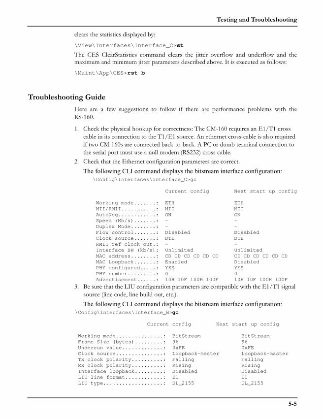
Testing and Troubleshooting
5-5
clears the statistics displayed by:
\View\Interfaces\Interface_C>st
The CES ClearStatistics command clears the jitter overflow and underflow and themaximum and minimum jitter parameters described above. It is executed as follows:
\Maint\App\CES>rst b
Troubleshooting GuideHere are a few suggestions to follow if there are performance problems with theRS-160.
1. Check the physical hookup for correctness: The CM-160 requires an E1/T1 cross cable in its connection to the T1/E1 source. An ethernet cross-cable is also required if two CM-160s are connected back-to-back. A PC or dumb terminal connection to the serial port must use a null modem (RS232) cross cable.
2. Check that the Ethernet configuration parameters are correct.The following CLI command displays the bitstream interface configuration:
\Config\Interfaces\Interface_C>gc
Current config Next start up config
Working mode.......: ETH ETH MII/RMII...........: MII MII AutoNeg............: ON ON Speed (Mb/s).......: - - Duplex Mode........: - - Flow control.......: Disabled Disabled Clock source.......: DTE DTE RMII ref clock out.: - - Interface BW (kb/s): Unlimited Unlimited MAC address........: CD CD CD CD CD CD CD CD CD CD CD CD MAC Loopback.......: Enabled Disabled PHY configured.....: YES YES PHY number.........: 0 0 Advertisement......: 10H 10F 100H 100F 10H 10F 100H 100F
3. Be sure that the LIU configuration parameters are compatible with the E1/T1 signal source (line code, line build out, etc.). The following CLI command displays the bitstream interface configuration:
\Config\Interfaces\Interface_B>gc
Current config Next start up config
Working mode...............: BitStream BitStream Frame Size (bytes).........: 96 96 Underrun value.............: 0xFE 0xFE Clock source...............: Loopback-master Loopback-master Tx clock polarity..........: Falling Falling Rx clock polarity..........: Rising Rising Interface loopback.........: Disabled Disabled LIU line format............: E1 E1 LIU type...................: DL_2155 DL_2155

Testing and Troubleshooting
5-6
LIU line code..............: HDB3 HDB3 LIU line build out.........: E1_75 E1_75 LIU rx term................: 100ohm 100ohm LIU monitor gain...........: Norm Norm LIU Rx Equlizer Gain Limit.: -12db -12db LIU Jitter Attenuation.....: Disabled Disabled LIU loopback...............: Disabled Disabled
The Interface C gs command shows whether the link to the Ethernet is operational and whether the PHY has connected properly. Check your settings if this status report shows that there are problems.
4. Confirm that the configuration of the RS-160 pair is compatible and consistent. See “Configuring a Pair of RS-160s” on page 1-5.The CES GetStatus (gs) command (see page 5-4) shows whether there is connec-tivity with the peer RS-160 and the peer is reachable.
5. If the Tx clocks on both RS-160s are configured as Loopback-Master, make sure that the clock source driving both units is stable. Otherwise, change one of the units to Recovered-Slave. Operating both units as Slave is not recommended and may pro-duce unpredictable results.
Table 5-3 lists observations and suggested causes and corrections.
If you have any questions, problems or suggestions with your Redux product, contact usat [email protected]
TABLE 5-3. Observations and Corrections
Observations Possible Cause Corrections
Jitter overflow and underflow is occurring on both RS-160s
The maximum jitter setting is too low.
Look at the ping round-trip time on the CES GetStatus display. This is an indication of the network delay. The maximum jitter should be at least this long.
Wide variation between maximum and minimum jitter levels but no occurrence of jitter overflow or underflow
The jitter buffer is operating correctly. There is variability in the packet network possibly due to congestion.
If the minimum is close to zero or the maximum close to twice the maximum jitter setting, increase the maximum jitter setting to avoid future overflow or underflow.
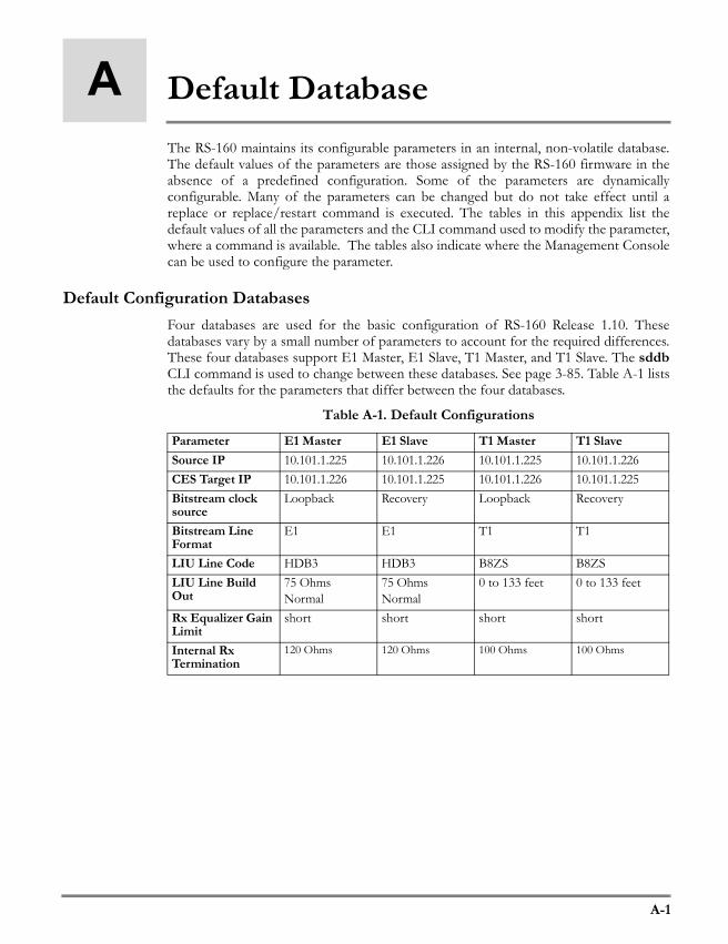
A-1
A Default DatabaseThe RS-160 maintains its configurable parameters in an internal, non-volatile database.The default values of the parameters are those assigned by the RS-160 firmware in theabsence of a predefined configuration. Some of the parameters are dynamicallyconfigurable. Many of the parameters can be changed but do not take effect until areplace or replace/restart command is executed. The tables in this appendix list thedefault values of all the parameters and the CLI command used to modify the parameter,where a command is available. The tables also indicate where the Management Consolecan be used to configure the parameter.
Default Configuration DatabasesFour databases are used for the basic configuration of RS-160 Release 1.10. Thesedatabases vary by a small number of parameters to account for the required differences.These four databases support E1 Master, E1 Slave, T1 Master, and T1 Slave. The sddbCLI command is used to change between these databases. See page 3-85. Table A-1 liststhe defaults for the parameters that differ between the four databases.
Table A-1. Default Configurations
Parameter E1 Master E1 Slave T1 Master T1 SlaveSource IP 10.101.1.225 10.101.1.226 10.101.1.225 10.101.1.226CES Target IP 10.101.1.226 10.101.1.225 10.101.1.226 10.101.1.225Bitstream clock source
Loopback Recovery Loopback Recovery
Bitstream Line Format
E1 E1 T1 T1
LIU Line Code HDB3 HDB3 B8ZS B8ZSLIU Line Build Out
75 OhmsNormal
75 OhmsNormal
0 to 133 feet 0 to 133 feet
Rx Equalizer Gain Limit
short short short short
Internal RxTermination
120 Ohms 120 Ohms 100 Ohms 100 Ohms

A-2
Main ParametersTable A-2. Main Parameters
Ethernet ParametersTable A-3. Ethernet Parameters (UPLINK)
Table A-4. Ethernet Parameters (LAN)
Parameter Default Value CLI Functions Mgt. ConsoleDefault Gateway IP address
10.101.1.1 SetDefGatewayIPaddr (sgip)
Product Version 1.10
Product Name RS-160Model A0100ETEB0000
Serial Number Undefined
Parameter Default Value CLI FunctionsMgt.Console
Flow Control Disable SetConfigEthFlow-Control (scef)
Auto Negotiation Enable SetConfigEth (sce)Rate - SetConfigEth (sce)Duplex Mode - SetConfigEth (sce)AutoNeg Advertise 10/100 Mbits
Half/Full DuplexBandwidth Limit Unlimited SetConfigEthLimit
(cel)
Parameter Default Value CLI FunctionsMgt.Console
Flow Control Disable SetConfigEthFlow-Control (scef)
Auto Negotiation Enable SetConfigEth (sce)Rate - SetConfigEth (sce)Duplex Mode - SetConfigEth (sce)AutoNeg Advertise 10/100 Mbits
Half/Full DuplexBandwidth Limit Unlimited SetConfigEthLimit
(cel)

A-3
E1/T1 Interface ParametersTable A-5. Bitstream Parameters (E1/T1 Interface)
Console ParametersTable A-6. ConsoleParameters
Static IP ParametersTable A-7. Static IP Parameters
Bridging Service (LAN Interface)Table A-8. Bridging Parameters
Parameter Default Value CLI FunctionsMgt.Console
LIU Line format E1 SetDefaultDB (sddb)Underrun value 0xFE SetConfigBitStreamUnderVal (sbuv)Clocking mode Loopback (Master)
or Recovery (Slave) SetDefaultDB (sddb)
Line Build Out 75 Ohm normal SetConfigLIUlineBuildout (sltt)Jitter Attenuator Disable SetConfigJitterAttenuation (sljt)Rx Equalizer Gain Limit
Short Haul SetRxEqualizerGainLimit (sreg)
Monitor Gain Normal operation SetConfigMonitorGain (slrg)Internal Rx Term 120 Ohm Enabled SetConfigLIURxTerm (slrt)Line code HDB3 SetConfigLIULineCode (sllc)Framing Mode Unframed SetFrameMode (sfm)Line Status Trap DisabledCircuit Identifier Null string
Parameter Default Value CLI FunctionsMgt.Console
Stop Bits 1 bit SetConfigUART (scu)Baud Rate 115200 SetConfigUART (scu)
Parameter Default Value CLI FunctionsMgt.Console
IP address UPLINK/LAN-10.101.1.225 (Master)10.101.1.226 (Slave)
SetStaticIP(ssip)
Subnet mask UPLINK/LAN-255.255.255.0
SetSubNetMask(ssnm)
Parameter Default Value CLI FunctionsMgt.Console
Enabled/Dis-abled
Disabled SetBridging(sb)
Aging Time 30 seconds SetAgingTime(sat)
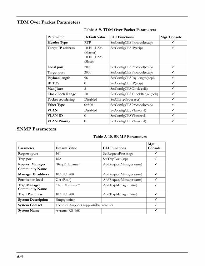
A-4
TDM Over Packet ParametersTable A-9. TDM Over Packet Parameters
SNMP ParametersTable A-10. SNMP Parameters
Parameter Default Value CLI Functions Mgt. ConsoleHeader Type RTP SetConfigCESProtocol(ccap)Target IP address 10.101.1.226
(Master)10.101.1.225 (Slave)
SetConfigCESIP(ccip)
Local port 2000 SetConfigCESProtocol(ccap)Target port 2000 SetConfigCESProtocol(ccap)Payload length 96 SetConfigCESPayLength(ccpl)IP TOS 0 SetConfigCESIP(ccip)Max Jitter 5 SetConfigCESClock(cclk)Clock Lock Range 50 SetConfigCES ClockRange (cclr)Packet reordering Disabled SetCESreOrder (scr)Ether Type 0x800 SetConfigCESProtocol(ccap)VLAN Disabled SetConfigCESVlan(ccvl)VLAN ID 0 SetConfigCESVlan(ccvl)VLAN Priority 0 SetConfigCESVlan(ccvl)
Parameter Default Value CLI FunctionsMgt. Console
Request port 161 SetRequestPort (srp)Trap port 162 SetTrapPort (stp)Request Manager Community Name
"Req Dflt name” AddRequestManager (arm)
Manager IP address 10.101.1.200 AddRequestManager (arm)Permission level Get (Read) AddRequestManager (arm)Trap Manager Community Name
"Trp Dflt name” AddTrapManager (atm)
Trap IP address 10.101.1.200 AddTrapManager (atm)System Description Empty stringSystem Contact Technical Support [email protected] Name ArrantoRS-160