ipmux-24 - radproductsonline€¦ · ipmux-24, based on or derived in any way from the ipmux-24....
TRANSCRIPT
IPmux-24 TDM Pseudowire Access Gateway
Version 1.5
INSTA
LLATIO
N A
ND
O
PER
ATIO
N M
AN
UA
L
The Access Company


IPmux-24 TDM Pseudowire Access Gateway
Version 1.5
Installation and Operation Manual
Notice
This manual contains information that is proprietary to RAD Data Communications Ltd. ("RAD"). No part of this publication may be reproduced in any form whatsoever without prior written approval by RAD Data Communications.
Right, title and interest, all information, copyrights, patents, know-how, trade secrets and other intellectual property or other proprietary rights relating to this manual and to the IPmux-24 and any software components contained therein are proprietary products of RAD protected under international copyright law and shall be and remain solely with RAD.
The IPmux-24 product name is owned by RAD. No right, license, or interest to such trademark is granted hereunder, and you agree that no such right, license, or interest shall be asserted by you with respect to such trademark. The RAD name, logo, logotype, and the terms EtherAccess, TDMoIP and TDMoIP Driven, and the product names Optimux and IPmux, are registered trademarks of RAD Data Communications Ltd. All other trademarks are the property of their respective holders.
You shall not copy, reverse compile or reverse assemble all or any portion of the Manual or the IPmux-24. You are prohibited from, and shall not, directly or indirectly, develop, market, distribute, license, or sell any product that supports substantially similar functionality as the IPmux-24, based on or derived in any way from the IPmux-24. Your undertaking in this paragraph shall survive the termination of this Agreement.
This Agreement is effective upon your opening of the IPmux-24 package and shall continue until terminated. RAD may terminate this Agreement upon the breach by you of any term hereof. Upon such termination by RAD, you agree to return to RAD the IPmux-24 and all copies and portions thereof.
For further information contact RAD at the address below or contact your local distributor.
International Headquarters RAD Data Communications Ltd.
24 Raoul Wallenberg Street Tel Aviv 69719, Israel Tel: 972-3-6458181 Fax: 972-3-6498250, 6474436 E-mail: [email protected]
North America Headquarters RAD Data Communications Inc.
900 Corporate Drive Mahwah, NJ 07430, USA Tel: (201) 5291100, Toll free: 1-800-4447234 Fax: (201) 5295777 E-mail: [email protected]
© 1999–2008 RAD Data Communications Ltd. Publication No. 488-200-11/08
Limited Warranty
RAD warrants to DISTRIBUTOR that the hardware in the IPmux-24 to be delivered hereunder shall be free of defects in material and workmanship under normal use and service for a period of twelve (12) months following the date of shipment to DISTRIBUTOR.
If, during the warranty period, any component part of the equipment becomes defective by reason of material or workmanship, and DISTRIBUTOR immediately notifies RAD of such defect, RAD shall have the option to choose the appropriate corrective action: a) supply a replacement part, or b) request return of equipment to its plant for repair, or c) perform necessary repair at the equipment's location. In the event that RAD requests the return of equipment, each party shall pay one-way shipping costs.
RAD shall be released from all obligations under its warranty in the event that the equipment has been subjected to misuse, neglect, accident or improper installation, or if repairs or modifications were made by persons other than RAD's own authorized service personnel, unless such repairs by others were made with the written consent of RAD.
The above warranty is in lieu of all other warranties, expressed or implied. There are no warranties which extend beyond the face hereof, including, but not limited to, warranties of merchantability and fitness for a particular purpose, and in no event shall RAD be liable for consequential damages.
RAD shall not be liable to any person for any special or indirect damages, including, but not limited to, lost profits from any cause whatsoever arising from or in any way connected with the manufacture, sale, handling, repair, maintenance or use of the IPmux-24, and in no event shall RAD's liability exceed the purchase price of the IPmux-24.
DISTRIBUTOR shall be responsible to its customers for any and all warranties which it makes relating to IPmux-24 and for ensuring that replacements and other adjustments required in connection with the said warranties are satisfactory.
Software components in the IPmux-24 are provided "as is" and without warranty of any kind. RAD disclaims all warranties including the implied warranties of merchantability and fitness for a particular purpose. RAD shall not be liable for any loss of use, interruption of business or indirect, special, incidental or consequential damages of any kind. In spite of the above RAD shall do its best to provide error-free software products and shall offer free Software updates during the warranty period under this Agreement.
RAD's cumulative liability to you or any other party for any loss or damages resulting from any claims, demands, or actions arising out of or relating to this Agreement and the IPmux-24 shall not exceed the sum paid to RAD for the purchase of the IPmux-24. In no event shall RAD be liable for any indirect, incidental, consequential, special, or exemplary damages or lost profits, even if RAD has been advised of the possibility of such damages.
This Agreement shall be construed and governed in accordance with the laws of the State of Israel.
Product Disposal
To facilitate the reuse, recycling and other forms of recovery of waste equipment in protecting the environment, the owner of this RAD product is required to refrain from disposing of this product as unsorted municipal waste at the end of its life cycle. Upon termination of the unit’s use, customers should provide for its collection for reuse, recycling or other form of environmentally conscientious disposal.

General Safety Instructions
The following instructions serve as a general guide for the safe installation and operation of telecommunications products. Additional instructions, if applicable, are included inside the manual.
Safety Symbols
This symbol may appear on the equipment or in the text. It indicates potential safety hazards regarding product operation or maintenance to operator or service personnel.
Danger of electric shock! Avoid any contact with the marked surface while the product is energized or connected to outdoor telecommunication lines.
Protective ground: the marked lug or terminal should be connected to the building protective ground bus.
Some products may be equipped with a laser diode. In such cases, a label with the laser class and other warnings as applicable will be attached near the optical transmitter. The laser warning symbol may be also attached.
Please observe the following precautions:
• Before turning on the equipment, make sure that the fiber optic cable is intact and is connected to the transmitter.
• Do not attempt to adjust the laser drive current.
• Do not use broken or unterminated fiber-optic cables/connectors or look straight at the laser beam.
• The use of optical devices with the equipment will increase eye hazard.
• Use of controls, adjustments or performing procedures other than those specified herein, may result in hazardous radiation exposure.
ATTENTION: The laser beam may be invisible!
In some cases, the users may insert their own SFP laser transceivers into the product. Users are alerted that RAD cannot be held responsible for any damage that may result if non-compliant transceivers are used. In particular, users are warned to use only agency approved products that comply with the local laser safety regulations for Class 1 laser products.
Always observe standard safety precautions during installation, operation and maintenance of this product. Only qualified and authorized service personnel should carry out adjustment, maintenance or repairs to this product. No installation, adjustment, maintenance or repairs should be performed by either the operator or the user.
Warning
Warning

Handling Energized Products
General Safety Practices
Do not touch or tamper with the power supply when the power cord is connected. Line voltages may be present inside certain products even when the power switch (if installed) is in the OFF position or a fuse is blown. For DC-powered products, although the voltages levels are usually not hazardous, energy hazards may still exist.
Before working on equipment connected to power lines or telecommunication lines, remove jewelry or any other metallic object that may come into contact with energized parts.
Unless otherwise specified, all products are intended to be grounded during normal use. Grounding is provided by connecting the mains plug to a wall socket with a protective ground terminal. If a ground lug is provided on the product, it should be connected to the protective ground at all times, by a wire with a diameter of 18 AWG or wider. Rack-mounted equipment should be mounted only in grounded racks and cabinets.
Always make the ground connection first and disconnect it last. Do not connect telecommunication cables to ungrounded equipment. Make sure that all other cables are disconnected before disconnecting the ground.
Some products may have panels secured by thumbscrews with a slotted head. These panels may cover hazardous circuits or parts, such as power supplies. These thumbscrews should therefore always be tightened securely with a screwdriver after both initial installation and subsequent access to the panels.
Connecting AC Mains
Make sure that the electrical installation complies with local codes.
Always connect the AC plug to a wall socket with a protective ground.
The maximum permissible current capability of the branch distribution circuit that supplies power to the product is 16A (20A for USA and Canada). The circuit breaker in the building installation should have high breaking capacity and must operate at short-circuit current exceeding 35A (40A for USA and Canada).
Always connect the power cord first to the equipment and then to the wall socket. If a power switch is provided in the equipment, set it to the OFF position. If the power cord cannot be readily disconnected in case of emergency, make sure that a readily accessible circuit breaker or emergency switch is installed in the building installation.
In cases when the power distribution system is IT type, the switch must disconnect both poles simultaneously.
Connecting DC Power
Unless otherwise specified in the manual, the DC input to the equipment is floating in reference to the ground. Any single pole can be externally grounded.
Due to the high current capability of DC power systems, care should be taken when connecting the DC supply to avoid short-circuits and fire hazards.
Make sure that the DC power supply is electrically isolated from any AC source and that the installation complies with the local codes.

The maximum permissible current capability of the branch distribution circuit that supplies power to the product is 16A (20A for USA and Canada). The circuit breaker in the building installation should have high breaking capacity and must operate at short-circuit current exceeding 35A (40A for USA and Canada).
Before connecting the DC supply wires, ensure that power is removed from the DC circuit. Locate the circuit breaker of the panel board that services the equipment and switch it to the OFF position. When connecting the DC supply wires, first connect the ground wire to the corresponding terminal, then the positive pole and last the negative pole. Switch the circuit breaker back to the ON position.
A readily accessible disconnect device that is suitably rated and approved should be incorporated in the building installation.
If the DC power supply is floating, the switch must disconnect both poles simultaneously.
Connecting Data and Telecommunications Cables
Data and telecommunication interfaces are classified according to their safety status.
The following table lists the status of several standard interfaces. If the status of a given port differs from the standard one, a notice will be given in the manual.
Ports Safety Status
V.11, V.28, V.35, V.36, RS-530, X.21, 10 BaseT, 100 BaseT, Unbalanced E1, E2, E3, STM, DS-2, DS-3, S-Interface ISDN, Analog voice E&M
SELV Safety Extra Low Voltage:
Ports which do not present a safety hazard. Usually up to 30 VAC or 60 VDC.
xDSL (without feeding voltage), Balanced E1, T1, Sub E1/T1
TNV-1 Telecommunication Network Voltage-1:
Ports whose normal operating voltage is within the limits of SELV, on which overvoltages from telecommunications networks are possible.
FXS (Foreign Exchange Subscriber) TNV-2 Telecommunication Network Voltage-2:
Ports whose normal operating voltage exceeds the limits of SELV (usually up to 120 VDC or telephone ringing voltages), on which overvoltages from telecommunication networks are not possible. These ports are not permitted to be directly connected to external telephone and data lines.
FXO (Foreign Exchange Office), xDSL (with feeding voltage), U-Interface ISDN
TNV-3 Telecommunication Network Voltage-3:
Ports whose normal operating voltage exceeds the limits of SELV (usually up to 120 VDC or telephone ringing voltages), on which overvoltages from telecommunication networks are possible.
Always connect a given port to a port of the same safety status. If in doubt, seek the assistance of a qualified safety engineer.
Always make sure that the equipment is grounded before connecting telecommunication cables. Do not disconnect the ground connection before disconnecting all telecommunications cables.
Some SELV and non-SELV circuits use the same connectors. Use caution when connecting cables. Extra caution should be exercised during thunderstorms.

When using shielded or coaxial cables, verify that there is a good ground connection at both ends. The grounding and bonding of the ground connections should comply with the local codes.
The telecommunication wiring in the building may be damaged or present a fire hazard in case of contact between exposed external wires and the AC power lines. In order to reduce the risk, there are restrictions on the diameter of wires in the telecom cables, between the equipment and the mating connectors.
To reduce the risk of fire, use only No. 26 AWG or larger telecommunication line cords.
Pour réduire les risques s’incendie, utiliser seulement des conducteurs de télécommunications 26 AWG ou de section supérieure.
Some ports are suitable for connection to intra-building or non-exposed wiring or cabling only. In such cases, a notice will be given in the installation instructions.
Do not attempt to tamper with any carrier-provided equipment or connection hardware.
Electromagnetic Compatibility (EMC)
The equipment is designed and approved to comply with the electromagnetic regulations of major regulatory bodies. The following instructions may enhance the performance of the equipment and will provide better protection against excessive emission and better immunity against disturbances.
A good ground connection is essential. When installing the equipment in a rack, make sure to remove all traces of paint from the mounting points. Use suitable lock-washers and torque. If an external grounding lug is provided, connect it to the ground bus using braided wire as short as possible.
The equipment is designed to comply with EMC requirements when connecting it with unshielded twisted pair (UTP) cables. However, the use of shielded wires is always recommended, especially for high-rate data. In some cases, when unshielded wires are used, ferrite cores should be installed on certain cables. In such cases, special instructions are provided in the manual.
Disconnect all wires which are not in permanent use, such as cables used for one-time configuration.
The compliance of the equipment with the regulations for conducted emission on the data lines is dependent on the cable quality. The emission is tested for UTP with 80 dB longitudinal conversion loss (LCL).
Unless otherwise specified or described in the manual, TNV-1 and TNV-3 ports provide secondary protection against surges on the data lines. Primary protectors should be provided in the building installation.
The equipment is designed to provide adequate protection against electro-static discharge (ESD). However, it is good working practice to use caution when connecting cables terminated with plastic connectors (without a grounded metal hood, such as flat cables) to sensitive data lines. Before connecting such cables, discharge yourself by touching ground or wear an ESD preventive wrist strap.
Caution
Attention

FCC-15 User Information
This equipment has been tested and found to comply with the limits of the Class A digital device, pursuant to Part 15 of the FCC rules. These limits are designed to provide reasonable protection against harmful interference when the equipment is operated in a commercial environment. This equipment generates, uses and can radiate radio frequency energy and, if not installed and used in accordance with the Installation and Operation manual, may cause harmful interference to the radio communications. Operation of this equipment in a residential area is likely to cause harmful interference in which case the user will be required to correct the interference at his own expense.
Canadian Emission Requirements
This Class A digital apparatus meets all the requirements of the Canadian Interference-Causing Equipment Regulation.
Cet appareil numérique de la classe A respecte toutes les exigences du Règlement sur le matériel brouilleur du Canada.
Warning per EN 55022 (CISPR-22)
This is a class A product. In a domestic environment, this product may cause radio interference, in which case the user will be required to take adequate measures.
Cet appareil est un appareil de Classe A. Dans un environnement résidentiel, cet appareil peut provoquer des brouillages radioélectriques. Dans ces cas, il peut être demandé à l’utilisateur de prendre les mesures appropriées.
Das vorliegende Gerät fällt unter die Funkstörgrenzwertklasse A. In Wohngebieten können beim Betrieb dieses Gerätes Rundfunkströrungen auftreten, für deren Behebung der Benutzer verantwortlich ist.
Warning
Avertissement
Achtung

Fra
nça
is
Mise au rebut du produit
Afin de faciliter la réutilisation, le recyclage ainsi que d'autres formes de récupération d'équipement mis au rebut dans le cadre de la protection de l'environnement, il est demandé au propriétaire de ce produit RAD de ne pas mettre ce dernier au rebut en tant que déchet municipal non trié, une fois que le produit est arrivé en fin de cycle de vie. Le client devrait proposer des solutions de réutilisation, de recyclage ou toute autre forme de mise au rebut de cette unité dans un esprit de protection de l'environnement, lorsqu'il aura fini de l'utiliser.
Instructions générales de sécurité
Les instructions suivantes servent de guide général d'installation et d'opération sécurisées des produits de télécommunications. Des instructions supplémentaires sont éventuellement indiquées dans le manuel.
Symboles de sécurité
Ce symbole peut apparaitre sur l'équipement ou dans le texte. Il indique des risques potentiels de sécurité pour l'opérateur ou le personnel de service, quant à l'opération du produit ou à sa maintenance.
Danger de choc électrique ! Evitez tout contact avec la surface marquée tant que le produit est sous tension ou connecté à des lignes externes de télécommunications.
Mise à la terre de protection : la cosse ou la borne marquée devrait être connectée à la prise de terre de protection du bâtiment.
Avertissement
Glossary
Address A coded representation of the origin or destination of data.
Attenuation Signal power loss through equipment, lines or other transmission devices. Measured in decibels.
AWG The American Wire Gauge System, which specifies wire width.
Balanced A transmission line in which voltages on the two conductors are equal in magnitude, but opposite in polarity, with respect to ground.
Bandwidth The range of frequencies passing through a given circuit. The greater the bandwidth, the more information can be sent through the circuit in a given amount of time.
Bipolar Signaling method in E1/T1 representing a binary “1” by alternating positive and negative pulses, and a binary “0” by absence of pulses.
Bit The smallest unit of information in a binary system. Represents either a one or zero (“1” or “0”).
Bridge A device interconnecting local area networks at the OSI data link layer, filtering and forwarding frames according to media access control (MAC) addresses.
Buffer A storage device. Commonly used to compensate for differences in data rates or event timing when transmitting from one device to another. Also used to remove jitter.
Byte A group of bits (normally 8 bits in length).
Cell The 53-byte basic information unit within an ATM network. The user traffic is segmented into cells at the source and reassembled at the destination. An ATM cell consists of a 5-byte ATM header and a 48-byte ATM payload, which contains the user data.
CESoPSN Structure-aware TDM Circuit Emulation Service over Packet Switched Network. A method for encapsulating structured (NxDS0) Time Division Multiplexed (TDM) signals as pseudo-wires over packet switched networks (PSN).
Channel A path for electrical transmission between two or more points. Also called a link, line, circuit or facility.
Circuit Emulation Service
Technology for offering circuit emulation services over packet-switched networks. The service offers traditional TDM trunking (at n x 64 kbps, fractional E1/T1, E1/T1 or E3/T3) over a range of transport protocols, including Internet Protocol (IP), MPLS and Ethernet.
Clock A term for the source(s) of timing signals used in synchronous transmission.
Data Information represented in digital form, including voice, text, facsimile and video.

Diagnostics The detection and isolation of a malfunction or mistake in a communications device, network or system.
Encapsulation Encapsulating data is a technique used by layered protocols in which a low level protocol accepts a message from a higher level protocol, then places it in the data portion of the lower-level frame. The logistics of encapsulation require that packets traveling over a physical network contain a sequence of headers.
Ethernet A local area network (LAN) technology which has extended into the wide area networks. Ethernet operates at many speeds, including data rates of 10 Mbps (Ethernet), 100 Mbps (Fast Ethernet), 1,000 Mbps (Gigabit Ethernet), 10 Gbps, 40 Gbps, and 100 Gbps.
Flow Control A congestion control mechanism that results in an ATM system implementing flow control.
Frame A logical grouping of information sent as a link-layer unit over a transmission medium. The terms packet, datagram, segment, and message are also used to describe logical information groupings.
Framing At the physical and data link layers of the OSI model, bits are fit into units called frames. Frames contain source and destination information, flags to designate the start and end of the frame, plus information about the integrity of the frame. All other information, such as network protocols and the actual payload of data, is encapsulated in a packet, which is encapsulated in the frame.
Full Duplex A circuit or device permitting transmission in two directions (sending and receiving) at the same time.
G.703 An ITU standard for the physical and electrical characteristics of various digital interfaces, including those at 64 kbps and 2.048 Mbps.
Gateway Gateways are points of entrance and exit from a communications network. Viewed as a physical entity, a gateway is that node that translates between two otherwise incompatible networks or network segments. Gateways perform code and protocol conversion to facilitate traffic between data highways of differing architecture.
Impedance The combined effect of resistance, inductance and capacitance on a transmitted signal. Impedance varies at different frequencies.
Interface A shared boundary, defined by common physical interconnection characteristics, signal characteristics, and meanings of exchanged signals.

IP Address Also known as an Internet address. A unique string of numbers that identifies a computer or device on a TCP/IP network. The format of an IP address is a 32-bit numeric address written as four numbers from 0 to 255, separated by periods (for example, 1.0.255.123).
Jitter The deviation of a transmission signal in time or phase. It can introduce errors and loss of synchronization in high speed synchronous communications.
Loading The addition of inductance to a line in order to minimize amplitude distortion. Used commonly on public telephone lines to improve voice quality, it can make the lines impassable to high speed data, and baseband modems.
Loopback A type of diagnostic test in which the transmitted signal is returned to the sending device after passing through all or part of a communications link or network.
Manager An application that receives Simple Network Management Protocol (SNMP) information from an agent. An agent and manager share a database of information, called the Management Information Base (MIB). An agent can use a message called a traps-PDU to send unsolicited information to the manager. A manager that uses the RADview MIB can query the RAD device, set parameters, sound alarms when certain conditions appear, and perform other administrative tasks.
Master Clock The source of timing signals (or the signals themselves) that all network stations use for synchronization.
Network (1) An interconnected group of nodes. (2) A series of points, nodes, or stations connected by communications channels; the collection of equipment through which connections are made between data stations.
Packet An ordered group of data and control signals transmitted through a network, as a subset of a larger message.
Payload The 48-byte segment of the ATM cell containing user data. Any adaptation of user data via the AAL will take place within the payload.
Physical Layer Layer 1 of the OSI model. The layer concerned with electrical, mechanical, and handshaking procedures over the interface connecting a device to the transmission medium.
Port The physical interface to a computer or multiplexer, for connection of terminals and modems.
Protocol A formal set of conventions governing the formatting and relative timing of message exchange between two communicating systems.

Pseudowire Point-to-point connections set up to emulate (typically Layer 2) native services like ATM, Frame Relay, Ethernet, TDM, or SONET/SDH over an underlying common packet-switched network (Ethernet, MPLS or IP) core. Pseudowires are defined by the IETF PWE3 (pseudowire emulation edge-to-edge) working group.
SAToP Structure-Agnostic Time Division Multiplexing (TDM) over Packet. A method for encapsulating Time Division Multiplexing (TDM) bit-streams (T1, E1, T3, E3) that disregards any structure that may be imposed on these streams, in particular the structure imposed by the standard TDM framing.
Space In telecommunications, the absence of a signal. Equivalent to a binary 0.
T1 A digital transmission link with a capacity of 1.544 Mbps used in North America. Typically channelized into 24 DS0s, each capable of carrying a single voice conversation or data stream. Uses two pairs of twisted pair wires.
Throughput The amount of information transferred through the network between two users in a given period, usually measured in the number of packets per second (pps).
TDMoIP® TDM over IP is a standards-based pseudowire transport technology that extends voice, video or data circuits across packet-switched networks simply, transparently and economically. TDMoIP supports the multiple signaling standards, OAM mechanisms and clock recovery features demanded by TDM networks for carrying voice-grade telephony.

Fra
nça
is
Certains produits peuvent être équipés d'une diode laser. Dans de tels cas, une étiquette indiquant la classe laser ainsi que d'autres avertissements, le cas échéant, sera jointe près du transmetteur optique. Le symbole d'avertissement laser peut aussi être joint.
Veuillez observer les précautions suivantes :
• Avant la mise en marche de l'équipement, assurez-vous que le câble de fibre optique est intact et qu'il est connecté au transmetteur.
• Ne tentez pas d'ajuster le courant de la commande laser.
• N'utilisez pas des câbles ou connecteurs de fibre optique cassés ou sans terminaison et n'observez pas directement un rayon laser.
• L'usage de périphériques optiques avec l'équipement augmentera le risque pour les yeux.
• L'usage de contrôles, ajustages ou procédures autres que celles spécifiées ici pourrait résulter en une dangereuse exposition aux radiations.
ATTENTION : Le rayon laser peut être invisible !
Les utilisateurs pourront, dans certains cas, insérer leurs propres émetteurs-récepteurs Laser SFP dans le produit. Les utilisateurs sont avertis que RAD ne pourra pas être tenue responsable de tout dommage pouvant résulter de l'utilisation d'émetteurs-récepteurs non conformes. Plus particulièrement, les utilisateurs sont avertis de n'utiliser que des produits approuvés par l'agence et conformes à la réglementation locale de sécurité laser pour les produits laser de classe 1.
Respectez toujours les précautions standards de sécurité durant l'installation, l'opération et la maintenance de ce produit. Seul le personnel de service qualifié et autorisé devrait effectuer l'ajustage, la maintenance ou les réparations de ce produit. Aucune opération d'installation, d'ajustage, de maintenance ou de réparation ne devrait être effectuée par l'opérateur ou l'utilisateur.
Manipuler des produits sous tension
Règles générales de sécurité
Ne pas toucher ou altérer l'alimentation en courant lorsque le câble d'alimentation est branché. Des tensions de lignes peuvent être présentes dans certains produits, même lorsque le commutateur (s'il est installé) est en position OFF ou si le fusible est rompu. Pour les produits alimentés par CC, les niveaux de tension ne sont généralement pas dangereux mais des risques de courant peuvent toujours exister.
Avant de travailler sur un équipement connecté aux lignes de tension ou de télécommunications, retirez vos bijoux ou tout autre objet métallique pouvant venir en contact avec les pièces sous tension.
Sauf s'il en est autrement indiqué, tous les produits sont destinés à être mis à la terre durant l'usage normal. La mise à la terre est fournie par la connexion de la fiche principale à une prise murale équipée d'une borne protectrice de mise à la terre. Si une cosse de mise à la terre est fournie avec le produit, elle devrait être connectée à tout moment à une mise à la terre de protection par un conducteur de diamètre 18 AWG ou plus. L'équipement monté en châssis ne devrait être monté que sur des châssis et dans des armoires mises à la terre.
Branchez toujours la mise à la terre en premier et débranchez-la en dernier. Ne branchez pas des câbles de télécommunications à un équipement qui n'est pas mis à la terre. Assurez-vous que tous les autres câbles sont débranchés avant de déconnecter la mise à la terre.
Avertissement
Fra
nça
is
Connexion au courant du secteur
Assurez-vous que l'installation électrique est conforme à la réglementation locale.
Branchez toujours la fiche de secteur à une prise murale équipée d'une borne protectrice de mise à la terre.
La capacité maximale permissible en courant du circuit de distribution de la connexion alimentant le produit est de 16A (20A aux Etats-Unis et Canada). Le coupe-circuit dans l'installation du bâtiment devrait avoir une capacité élevée de rupture et devrait fonctionner sur courant de court-circuit dépassant 35A (40A aux Etats-Unis et Canada).
Branchez toujours le câble d'alimentation en premier à l'équipement puis à la prise murale. Si un commutateur est fourni avec l'équipement, fixez-le en position OFF. Si le câble d'alimentation ne peut pas être facilement débranché en cas d'urgence, assurez-vous qu'un coupe-circuit ou un disjoncteur d'urgence facilement accessible est installé dans l'installation du bâtiment.
Le disjoncteur devrait déconnecter simultanément les deux pôles si le système de distribution de courant est de type IT.
Connexion d'alimentation CC
Sauf s'il en est autrement spécifié dans le manuel, l'entrée CC de l'équipement est flottante par rapport à la mise à la terre. Tout pôle doit être mis à la terre en externe.
A cause de la capacité de courant des systèmes à alimentation CC, des précautions devraient être prises lors de la connexion de l'alimentation CC pour éviter des courts-circuits et des risques d'incendie.
Assurez-vous que l'alimentation CC est isolée de toute source de courant CA (secteur) et que l'installation est conforme à la réglementation locale.
La capacité maximale permissible en courant du circuit de distribution de la connexion alimentant le produit est de 16A (20A aux Etats-Unis et Canada). Le coupe-circuit dans l'installation du bâtiment devrait avoir une capacité élevée de rupture et devrait fonctionner sur courant de court-circuit dépassant 35A (40A aux Etats-Unis et Canada).
Avant la connexion des câbles d'alimentation en courant CC, assurez-vous que le circuit CC n'est pas sous tension. Localisez le coupe-circuit dans le tableau desservant l'équipement et fixez-le en position OFF. Lors de la connexion de câbles d'alimentation CC, connectez d'abord le conducteur de mise à la terre à la borne correspondante, puis le pôle positif et en dernier, le pôle négatif. Remettez le coupe-circuit en position ON.
Un disjoncteur facilement accessible, adapté et approuvé devrait être intégré à l'installation du bâtiment.
Le disjoncteur devrait déconnecter simultanément les deux pôles si l'alimentation en courant CC est flottante.

Declaration of Conformity
Manufacturer's Name: RAD Data Communications Ltd.
Manufacturer's Address: 24 Raoul Wallenberg St., Tel Aviv 69719, Israel
declares that the product:
Product Name: IPmux-24
conforms to the following standard(s) or other normative document(s):
EMC: EN 55022:1998 + A1:2000, A2:2003
Information technology equipment – Radio disturbance characteristics – Limits and methods of measurement.
EN 50024: 1998 A1:2001, A2:2003
Information technology equipment – Immunity characteristics – Limits and methods of measurement.
EN 61000-3-2:2000 + A2:2005
Electromagnetic compatibility (EMC) - Part 3-2: Limits - Limits for harmonic current emissions (equipment input current up to and including 16A per phase).
EN 61000-3-3:1995 + A1:2001
Electromagnetic compatibility (EMC) - Part 3-3: Limits - Limitation of voltage changes, voltage fluctuations and flicker in public low voltage supply systems, for equipment with rated current ≤16A per phase and not subject to conditional connection.
Safety: EN 60950-1:2001 + A11:2004
Information technology equipment – Safety – Part 1: General requirements.
Supplementary Information:
The product herewith complies with the requirements of the EMC Directive 2004/108/EC, the Low Voltage Directive 2006/95/EC and the R&TTE Directive 99/5/EC for wired equipment. The product was tested in a typical configuration.
Tel Aviv, 22 February, 2008
Haim Karshen
VP Quality
European Contact: RAD Data Communications GmbH, Otto-Hahn-Str. 28-30, 85521 Ottobrunn-Riemerling, Germany

IPmux-24 Ver. 1.5 Configuring IPmux-24 1
Quick Start Guide
Installation of IPmux-24 should be carried out only by an experienced technician. If you are familiar with IPmux-24, use this guide to prepare the unit for operation.
1. Installing IPmux-24
Connecting the Interfaces
1. Connect the network interface to the connector designated ETH 1.
2. Connect the user LAN(s) to the connector(s) designated ETH 2 or ETH 3.
3. Connect the E1 or T1 lines to the RJ-45 connectors designated E1 or T1.
When connecting balanced E1 or T1 equipment, make sure to use only 4-wire RJ-45 connectors with the following pins used for receiving and transmitting data: 1, 2, 4, 5. Do not use 8-pin RJ-45 connectors.
4. Connect the control terminal to the rear panel CONTROL connector.
or
Connect a Telnet host, or a PC running a Web browsing application to one of the user LAN ports.
Connecting the Power
• Connect the power cable to the power connector on the IPmux-24 rear panel.
The unit has no power switch. Operation starts when the power is applied to the rear panel power connector.
2. Configuring IPmux-24
Configure IPmux-24 to the desired operation mode via an ASCII terminal connected to the rear panel CONTROL port. Alternatively, you can manage IPmux-24 over Telnet, or via a PC running a Web browsing application connected to one of the user LAN ports.
Caution
Quick Start Guide Installation and Operation Manual
2 Configuring IPmux-24 IPmux-24 Ver. 1.5
Starting a Terminal Session for the First Time
To start a terminal session:
1. Connect a terminal to the CONTROL connector of IPmux-24.
2. Turn on the control terminal PC and set its port parameters to 115,200 baud, 8 bits/character, 1 stop bit, no parity. Set the terminal emulator to ANSI VT100 emulation (for optimal view of system menus).
3. Power IPmux-24 up and proceed with the management session.
Configuring the IP Management Parameters
The host IP address, subnet mask, and default gateway IP address must be configured via an ASCII terminal.
To configure the IP management parameters:
• From the Host IP menu (Configuration > System > Management > Host IP), select an IP address of the IPmux-24 host.
Configuring the System Clock
IPmux-24 system timing mechanism ensures a single clock source for all TDM links by providing the master and fallback clocks.
To configure the system clock:
• From the System Clock menu (Configuration > System > System clock), select the master and fallback timing reference for IPmux-24.
Configuring E1 and T1 at the Physical Level
E1 and T1 interfaces must be configured at the physical level first.
To configure E1 and T1 at the physical level:
1. From the TDM Interface Type menu (Configuration > Physical layer > TDM interface type), select the TDM interface type, E1 or T1.
2. From the TDM Configuration menu (Configuration > Physical layer > TDM configuration), configure the necessary parameters of the E1 or T1 services.
Connecting Bundle
The E1/T1 timeslots must be assigned to a bundle. The bundle must be sent to the remote IP address and be connected to one of the destination bundles.
To assign timeslots to a bundle:
• From the DS0 Bundle Configuration menu (Main > Configuration > Connection > DS0 bundle configuration), assign desired timeslots to a bundle by setting them to 1.
Installation and Operation Manual Quick Start Guide
IPmux-24 Ver. 1.5 Configuring IPmux-24 3
To configure a PW host:
• From the PW Host IP menu (Configuration > Connection > PW host IP), define IP parameters of PW host. It is an IP host which receives pseudowire traffic generated by remote device.
To connect a bundle:
• From the Bundle Connection Configuration menu (Main > Configuration > Connection > Bundle connection configuration), configure the necessary bundle connection parameters.

Quick Start Guide Installation and Operation Manual
4 Configuring IPmux-24 IPmux-24 Ver. 1.5
IPmux-24 Ver. 1.5 i
Contents
Chapter 1. Introduction
1.1 Overview.................................................................................................................... 1-1 Device Options ....................................................................................................... 1-1 Applications ............................................................................................................ 1-2 Features ................................................................................................................. 1-2
E1 Interface ....................................................................................................... 1-2 T1 Interface ....................................................................................................... 1-2 Timing ................................................................................................................ 1-3 Packet Networks ................................................................................................ 1-3 Payload Encapsulation ........................................................................................ 1-4 QoS ................................................................................................................... 1-5 Ring Topology .................................................................................................... 1-5 Management ...................................................................................................... 1-5 Environment ...................................................................................................... 1-6
1.2 Physical Description ................................................................................................... 1-7 1.3 Functional Description ................................................................................................ 1-7
Service Type ........................................................................................................... 1-8 Unframed ........................................................................................................... 1-8 Fractional ........................................................................................................... 1-8 Fractional with CAS ............................................................................................ 1-8 HDLC.................................................................................................................. 1-8
Timeslot Assignment in a Bundle ............................................................................. 1-8 Testing ................................................................................................................... 1-9 Timing Modes ......................................................................................................... 1-9
E1/T1 Timing ...................................................................................................... 1-9 System Timing .................................................................................................... 1-9
Network Timing Schemes ........................................................................................ 1-9 External Network Timing ................................................................................... 1-10 Adaptive Timing ............................................................................................... 1-11
Frame Format ....................................................................................................... 1-11 IP Encapsulation (MPLS and IP Networks) .......................................................... 1-11 MPLS Encapsulation (Ethernet and MPLS Networks) .......................................... 1-14
Payload Encapsulation .......................................................................................... 1-14 Packet Delay Variation .......................................................................................... 1-16 PDVT (Jitter) Buffer ............................................................................................... 1-16 Packet Creation Time (PCT) ................................................................................... 1-17
TDMoIP ............................................................................................................ 1-17 CESoPSN .......................................................................................................... 1-17 SAToP .............................................................................................................. 1-18
Round Trip Delay .................................................................................................. 1-18 Ethernet Throughput ............................................................................................ 1-18 Pseudowire OAM .................................................................................................. 1-19 End-to-End Alarm Generation ................................................................................ 1-19 Trail-Extended Mode ............................................................................................. 1-19 VLAN Traffic Behavior ........................................................................................... 1-20 Bridge ................................................................................................................... 1-21 Double Host ......................................................................................................... 1-21 Ring Topology ....................................................................................................... 1-21 Management ........................................................................................................ 1-23
Security ........................................................................................................... 1-23

Table of Contents Installation and Operation Manual
ii IPmux-24 Ver. 1.5
QoS ...................................................................................................................... 1-23 Traffic Classification and Prioritization .............................................................. 1-23 Rate Limitation ................................................................................................ 1-23
L2CP Handling ....................................................................................................... 1-23 1.4 Technical Specifications ............................................................................................ 1-24
Chapter 2. Installation and Setup
2.1 Introduction ............................................................................................................... 2-1 2.2 Site Requirements and Prerequisites .......................................................................... 2-1 2.3 Package Contents ...................................................................................................... 2-1 2.4 Equipment Needed..................................................................................................... 2-2
Power Cable............................................................................................................ 2-2 Interface Cables ...................................................................................................... 2-2
2.5 Mounting the Unit ...................................................................................................... 2-2 2.6 Installing SFP Modules ................................................................................................ 2-3 2.7 Connecting to the Ethernet Equipment ....................................................................... 2-4 2.8 Connecting to the E1/T1 Devices ................................................................................ 2-4 2.9 Connecting to the ASCII Terminal ................................................................................ 2-5 2.10 Connecting to the External Clock Source ..................................................................... 2-6 2.11 Connecting to the External Alarm Device .................................................................... 2-6 2.12 Connecting to Power .................................................................................................. 2-6
Connecting AC Power .............................................................................................. 2-7 Connecting DC Power .............................................................................................. 2-7
Chapter 3. Operation
3.1 Turning On the Unit ................................................................................................... 3-1 3.2 Indicators .................................................................................................................. 3-1 3.3 Default Settings ......................................................................................................... 3-2 3.4 Configuration and Management Alternatives .............................................................. 3-7
Working with Terminal ............................................................................................ 3-7 Login ................................................................................................................. 3-7 Choosing Options ............................................................................................... 3-8 Ending a Terminal Configuration Session ............................................................. 3-9
Working with Web Terminal ..................................................................................... 3-9 Web Browser Requirements ............................................................................... 3-9 General Web Browsers Operating Procedures ................................................... 3-10
Working with RADview .......................................................................................... 3-11 Working with SNMP ............................................................................................... 3-11 Menu Maps ........................................................................................................... 3-11
3.5 Turning IPmux-24 Off ............................................................................................... 3-15
Chapter 4. Configuration
4.1 Configuring IPmux-24 for Management ....................................................................... 4-1 Configuring IP Host Parameters ............................................................................... 4-1
Configuring DHCP Client ..................................................................................... 4-2 Managing IP Parameters of the IPmux-24 Host ................................................... 4-2
Defining Read, Write and Trap Communities ............................................................ 4-3 Configuring the Host Encapsulation ......................................................................... 4-3 Assigning a Name to IPmux-24 and Its Location ...................................................... 4-4 Controlling the Authentication Failure Trap .............................................................. 4-5 Defining Network Managers .................................................................................... 4-5 Configuring SNMPv3 ................................................................................................ 4-6
Installation and Operation Manual Table of Contents
IPmux-24 Ver. 1.5 iii
Configuring the SNMP Engine ID ......................................................................... 4-7 Enabling SNMPv3 ................................................................................................ 4-7 Adding SNMPv3 Users ........................................................................................ 4-8 Adding Notification Entries ................................................................................. 4-9 Assigning Traps .................................................................................................. 4-9 Configuring Target Parameters ......................................................................... 4-10 Configuring Target Address .............................................................................. 4-11 Mapping SNMPv1 to SNMPv3 ............................................................................ 4-12
Configuring Management Access Permissions and Methods ................................... 4-12 Defining Management Access Permissions ........................................................ 4-12
Controlling Management Access ............................................................................ 4-14 Configuring RADIUS Client ..................................................................................... 4-15 Configuring Control Port Parameters ..................................................................... 4-16
4.2 Configuring IPmux-24 for Operation ......................................................................... 4-17 Setting Device-Level Parameters ........................................................................... 4-17
Configuring the System Clock ........................................................................... 4-17 Selecting the TDM Interface Type ..................................................................... 4-18 Configuring the Ring Protection ........................................................................ 4-18
Setting Physical Layer Parameters ......................................................................... 4-20 Configuring the E1 TDM Interface ..................................................................... 4-20 Configuring the E1 External Clock Interface Type ............................................... 4-22 Configuring the T1 TDM Interface ..................................................................... 4-23 Configuring Ethernet Interfaces ........................................................................ 4-26
Configuring Bundle Connections ............................................................................ 4-28 Configuring the Ethernet Bridge ............................................................................ 4-39
Configuring MAC Table ...................................................................................... 4-40 Configuring the Bridge Ports ............................................................................. 4-41 Configuring L2CP Handling ................................................................................ 4-43 Configuring the VLAN Membership .................................................................... 4-43
Configuring Quality of Service (QoS) ..................................................................... 4-45 Configuring the Traffic Priority .......................................................................... 4-45 Configuring Rate Limitation .............................................................................. 4-47
4.3 Additional Tasks ....................................................................................................... 4-49 Displaying the IPmux-24 Inventory ........................................................................ 4-49 Setting the Date and Time .................................................................................... 4-50 Displaying the IPmux-24 Status ............................................................................. 4-51
Displaying the Physical Layer Information ......................................................... 4-51 Displaying the Bundle Connection Information .................................................. 4-52 Displaying the System Clock Information .......................................................... 4-53 Displaying List of Connected Managers ............................................................. 4-54 Displaying the Ring Status Information ............................................................. 4-54
Transferring Software and Configuration Files ....................................................... 4-55 Resetting IPmux-24 ............................................................................................... 4-56
Resetting IPmux-24 to the Defaults .................................................................. 4-56 Resetting IPmux-24 .......................................................................................... 4-57
Chapter 5. Configuring IPmux-24 for Typical Applications
5.1 Overview.................................................................................................................... 5-1 Application ............................................................................................................. 5-1 Guidelines for Configuring the IPmux Units .............................................................. 5-2
5.2 Configuring the IPmux-24 Units .................................................................................. 5-2 Configuring the Management Host IP Parameters .................................................... 5-2 Configuring the Management Host Encapsulation .................................................... 5-3
Table of Contents Installation and Operation Manual
iv IPmux-24 Ver. 1.5
Configuring the Manager List .................................................................................. 5-3 Configuring E1 Parameters at the Physical Layer ...................................................... 5-4 Configuring the Pseudowire Host ............................................................................ 5-5 Configuring Bundles ................................................................................................ 5-5 Connecting the Bundles .......................................................................................... 5-6 Configuring the Bridge ............................................................................................ 5-7 Configuring the VLAN Membership .......................................................................... 5-8
5.3 Typical Pseudowire Application with Ring Protection ................................................... 5-8 Configuration Sequence .......................................................................................... 5-9 Configuring the Management Host ........................................................................ 5-10 Setting the TDM Physical Layer Parameters ........................................................... 5-10 Configuring the Pseudowire Host .......................................................................... 5-10 Configuring the Bridge .......................................................................................... 5-11 Configuring the VLAN Membership ........................................................................ 5-11 Enabling the Ring Functionality ............................................................................. 5-11 Configuring the Priority Classification Method........................................................ 5-12 Mapping the 802.1p Priorities to Traffic Classes .................................................... 5-12 Unmasking Ring Status Traps ................................................................................ 5-13 Configuring and Connecting the PW Bundles ......................................................... 5-14
Chapter 6. Diagnostics and Troubleshooting
6.1 Monitoring Performance ............................................................................................. 6-1 Displaying E1/T1 Statistics ...................................................................................... 6-1 Displaying Ethernet Statistics .................................................................................. 6-6 Displaying Bundle Connection Statistics ................................................................... 6-8
6.2 Detecting Errors ....................................................................................................... 6-11 Power-Up Self-Test ............................................................................................... 6-11
6.3 Displaying System Messages .................................................................................... 6-12 Accessing Event Log .............................................................................................. 6-12 Clearing Events ..................................................................................................... 6-14 Masking Alarm Traps ............................................................................................. 6-16
6.4 Troubleshooting ....................................................................................................... 6-17 6.5 Testing IPmux-24 ..................................................................................................... 6-17
Running Diagnostic Loopbacks .............................................................................. 6-18 External Loopback ............................................................................................ 6-18 Internal Loopback ............................................................................................ 6-18 Activating T1 Inband Loopbacks ........................................................................ 6-19
Pinging IP Hosts .................................................................................................... 6-21 Running a Trace Route .......................................................................................... 6-22
6.6 Frequently Asked Questions ..................................................................................... 6-23 6.7 Technical Support .................................................................................................... 6-26
Appendix A. Connector Wiring
Appendix B. Boot Sequence and Downloading Software

IPmux-24 Ver. 1.5 Overview 1-1
Chapter 1
Introduction
1.1 Overview
IPmux-24 offers a pseudowire (PW) solution for extending traditional E1/T1 services transparently over packet switched networks (PSNs) such as Ethernet, MPLS and IP networks. The device converts the data stream coming from its TDM ports into configurable-sized packets that are encapsulated using one of the PW methods (TDMoIP, CESoPSN, SAToP, HDLCoPSN) and forwarded over Ethernet, MPLS and IP networks. IPmux-24 offers end-to-end synchronization for voice/leased line applications. IPmux-24 also features two Gigabit or Fast Ethernet user ports for data (Ethernet) connectivity to the IP/Ethernet network. Management is performed locally by a terminal, or remotely via Web, Telnet, or SNMP.
Device Options
Several versions of the unit are available, offering different of TDM port types, different combinations of Ethernet ports, various clock recovery capabilities, and other special features (external clock, alarm relay etc).
• TDM ports: 1, 2 or 4 E1 or T1 ports
• Ethernet ports:
One SFP-based network port
One SFP- or UTP-based network/user port
One SFP- or UTP-based user port
• Clock recovery: standard or advanced clock recovery mechanism
• Carrier-class option: external clock, alarm relay, real-time clock
• Environmentally hardened (IPmux-24/H) option.
The unit can also be ordered with Fast Ethernet interfaces only (IPmux-24/FE).
Note
Chapter 1 Introduction Installation and Operation Manual
1-2 Overview IPmux-24 Ver. 1.5
Applications
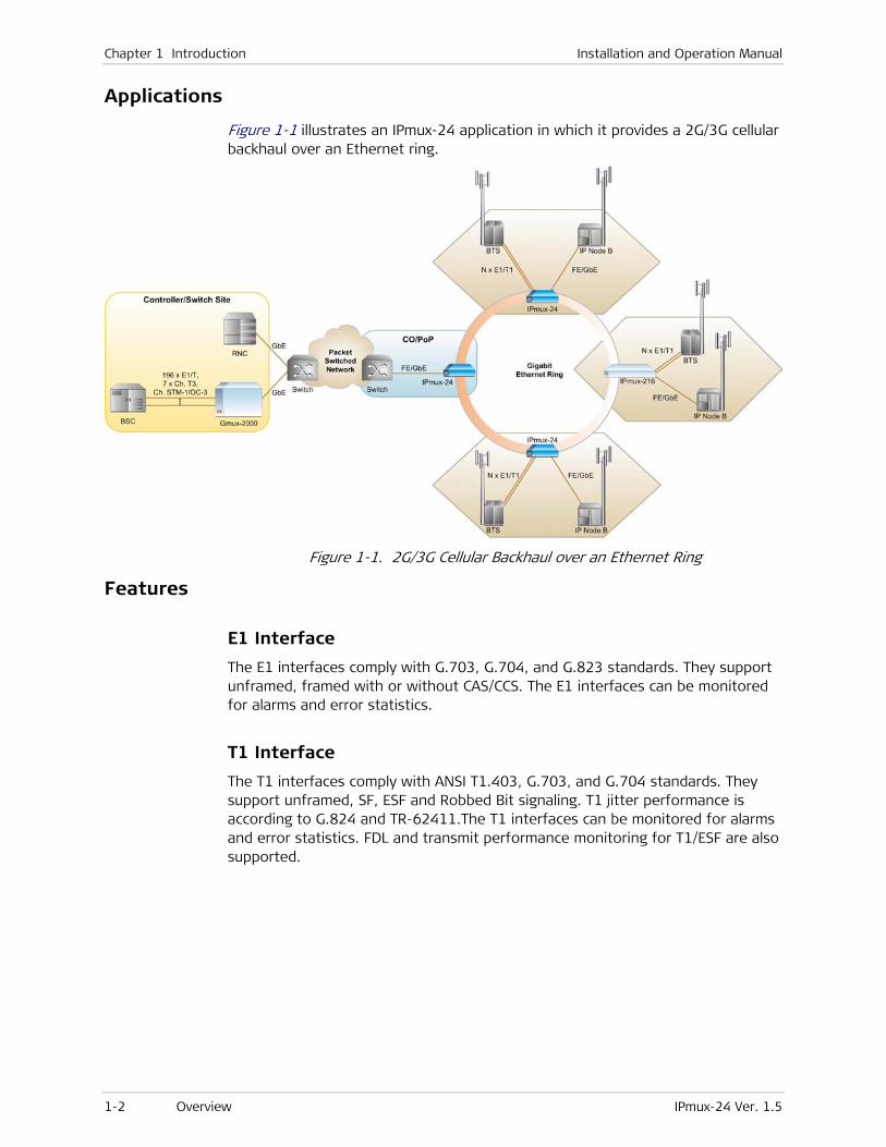
Figure 1-1 illustrates an IPmux-24 application in which it provides a 2G/3G cellular backhaul over an Ethernet ring.
Figure 1-1. 2G/3G Cellular Backhaul over an Ethernet Ring
Features
E1 Interface
The E1 interfaces comply with G.703, G.704, and G.823 standards. They support unframed, framed with or without CAS/CCS. The E1 interfaces can be monitored for alarms and error statistics.
T1 Interface
The T1 interfaces comply with ANSI T1.403, G.703, and G.704 standards. They support unframed, SF, ESF and Robbed Bit signaling. T1 jitter performance is according to G.824 and TR-62411.The T1 interfaces can be monitored for alarms and error statistics. FDL and transmit performance monitoring for T1/ESF are also supported.

Installation and Operation Manual Chapter 1 Introduction
IPmux-24 Ver. 1.5 Overview 1-3
Timing
IPmux-24 maintains synchronization between TDM devices by deploying advanced clock recovery mechanisms. Available timing modes are:
• Loopback (Rx clock)
• Adaptive
• Internal clock
• External clock.
System clock ensures single clock source for all TDM links. The system clock uses master and fallback timing sources for clock redundancy. IPmux-24 provides system clock output via external clock connector.
Advanced clock recovery mechanism complies with G.823 (clause 6) requirements, providing frequency accuracy of up to 16 ppb. This makes the unit suitable for timing-sensitive applications, such as cellular backhauling.
Packet Networks
IPmux-24 supports transmission over the following packet networks:
• Ethernet
• MPLS
• IP.
Ethernet
The Ethernet ports can be either UTP (10/100BaseT) or SFP-based fiber optic (1000BaseX or 100BaseFx):
• Network (ETH 1) – SFP or UTP
• Network/user (ETH 2) – SFP or UTP
• User (ETH 3) – SFP or UTP.
The Ethernet ports accept a wide range of Gigabit and Fast Ethernet SFP-based fiber optic interfaces. One or two ports can be ordered with built-in 10/100BaseT interfaces.
Bridge Modes
The following bridge modes are available:
• Transparent
• Filtered (VLAN-aware and VLAN-unaware).
Rate Limiting
Traffic rate is limited at the ingress and at the egress of the network and user ports. Frame type (broadcast, multicast or flooded unicast) is user-selectable.
Chapter 1 Introduction Installation and Operation Manual
1-4 Overview IPmux-24 Ver. 1.5
MPLS
IPmux-24 encapsulates PW payload with MPLS labels for transporting it over MPLS networks (TDMoMPLS, CESoMPLS, SATOPoMPLS, HDLCoMPLS). Saving up to 20 bytes of overhead in comparison to the standard PWoIP encapsulation, TDMoMPLS is ideal for bandwidth-sensitive networks.
IP
The data stream coming from the E1 or T1 port is converted into IP packets that are transported over the Gigabit or Fast Ethernet ports, and vice versa. TDM bytes are encapsulated in a UDP frame that runs over IP and over Ethernet. The number of TDM bytes in an IP frame is configurable for throughput/delay tradeoff. Each device has a two IP address (host IP and PW IP); the user can use the same IP address for host and PW traffic. A configurable destination IP address is assigned to the IP packets. IP ToS field support can be configured for IP Level Priority.
Payload Encapsulation
Payload is encapsulated using the following methods:
• TDMoIP
• CESoPSN
• SAToP
• HDLCoPSN.
TDMoIP
TDMoIP (TDM over IP) payload encapsulation is implemented according to IETF RFC 5087 and ITU-T Y.1413. It uses AAL1 format for constant rate/static allocation of timeslots. The TDMoIP packet size is a multiple of 48 bytes. TDMoIP encapsulation can be used with framed or unframed TDM service. It supports FDL bit in T1 used for activating inband loopbacks.
CESoPSN
CESoPSN (Circuit Emulation Service over PSN) is a structure-aware format for framed E1/T1 services. It converts structured E1/T1 data flows into IP or MPLS packets and vice versa with static assignment of timeslots inside a bundle according to ITU-T Y.1413 and IETF RFC 5086. The CESoPSN packet size is a multiple of TDM frame size.
SAToP
SAToP (Structure Agnostic TDM over Packet) encapsulation method is used to convert unframed E1/T1 data flows into IP or MPLS packets and vice versa according to ITU-T Y.1413 and IETF RFC 4553. It provides flexible packet size configuration and low end-to-end delay.

Installation and Operation Manual Chapter 1 Introduction
IPmux-24 Ver. 1.5 Overview 1-5
HDLCoPSN
IPmux-24 also supports HDLCoPSN (HDLCoMPLS and HDLCoIP) transmission. This makes IPmux-24 suitable for the following data transfer applications:
• Port-mode Frame Relay (FRAD)
• Transparent X.25 (PAD)
• Transparent PPP (router).
The HDLCoPSN is implemented in IPmux-24 according to the IETF RFC 4618 (excluding clause 5.3 – PPP) and RFC 5087. The HDLC uses bit stuffing to ensure the bits stream continuity. The HDLC frames include the 16-bit FCS for the frame validity check.
QoS
QoS supports:
• Labeling IP level priority (ToS/Diffserv) for PW packets
• VLAN tagging and priority labeling according to IEEE 802.1p&Q for PW packets
• Using EXP bits for QoS marking of the PW traffic in MPLS networks.
The user can configure the ToS (Type of Service) of the outgoing TDMoIP packets. This allows an en-route Layer 3 router or switch, which supports ToS, to give higher priority to IPmux-24 TDMoIP traffic for delay-sensitive and secure applications. IPmux-24 allows you to configure the WHOLE ToS byte field, since different vendors may use different bits to tag packets for traffic prioritization. This also enables operation according to various RFC definitions (for example RFC 2474, RFC 791). The user can also configure VLAN priority bits for Level 2 priority.
Ring Topology
The ring topology is used to protect the transmission path, when data propagates over two alternative paths (“clockwise” or ”counterclockwise”). To comply with the Ethernet protocol characteristics, an arbitrary pair of adjacent nodes on the ring keep the ring open by disconnecting a ring segment, thereby preventing frames from making a full round trip. If a segment breaks (fails), the redundancy mechanism automatically moves the blocking nodes to the ends of the failed segment and reconnects the previously disconnected segment. Therefore, full connectivity is restored for any single point of failure. For pseudowire traffic and other user-specified traffic, this change takes effect within 50 msec.
A single ring may include up to 16 IPmux-24 devices and up to 16 VLAN plus an additional VLAN for management traffic.
Management
IPmux-24 can be managed locally by connecting an ASCII terminal to the RS-232 port on the rear panel, or via an HTTP connection (Web-based management tool), Telnet or SNMP. The SNMP management capability enables fully graphical, user-friendly management using the RADview Service Center

Chapter 1 Introduction Installation and Operation Manual
1-6 Overview IPmux-24 Ver. 1.5
TDMoIP network management stations offered by RAD, as well as management by other SNMP-based management systems.
Web Terminal
Web-based terminal management system for remote device configuration and maintenance is embedded into IPmux-24 and provided at no extra cost. The application can be run from any standard Web browser.
RADview-SC/TDMoIP
The RADview Service Center and Element Manager packages control and monitor pseudowire devices and circuits. The Service Center’s intuitive GUI, “point-and-click” functionality and easy-to-follow wizards increase the efficiency and accuracy of the service provisioning process.
Environment
IPmux-24/H is an environmentally hardened version intended for street-cabinet and cellular-tower installations.
Environmentally hardened (/H) version is not available for IPmux-24/FE. The /H version requires temperature-hardened SFP transceivers.
Note

Installation and Operation Manual Chapter 1 Introduction
IPmux-24 Ver. 1.5 Functional Description 1-7
1.2 Physical Description IPmux-24 is a compact, easy-to-install standalone unit. Figure 1-2 shows a 3D view of an IPmux-24 unit.
Figure 1-2. IPmux-24 3D View
The front panel includes the IPmux-24 LEDs. For the detailed LED description, see Chapter 3.
User, network, external clock and management ports, and the power supply connectors are located on the rear panel of the unit. For further details, see Chapter 2.
1.3 Functional Description
IPmux-24 provides TDM connectivity across the Ethernet, MPLS or IP network. A single bundle (group of timeslots) can be transmitted in a TDM pseudowire (PW) to a predefined far-end bundle. IPmux-24 supports ICMP (ping), and generates ARP in case of unknown next hop MAC addresses, answers ARP requests, and supports the 802.3 VLAN Ethernet format.
IPmux-24 includes one, two or four E1 or T1 ports. Traffic is transmitted over the network as E1/T1 or fractional E1/T1, using the TDMoIP, CESoPSN, SAToP or HDLCoPSN method.
IPmux-24 supports two Ethernet user ports for user LAN connectivity.
Configuration and management are provided via the IPmux-24 local terminal, Web-based management utility, Telnet or RADview management tool (SNMP).

Chapter 1 Introduction Installation and Operation Manual
1-8 Functional Description IPmux-24 Ver. 1.5
Service Type
This section describes the IPmux-24 operation modes, which are:
• Unframed E1/T1
• Fractional E1/T1
• Fractional E1/T1 with CAS
• HDLC.
Unframed
In the unframed mode, the incoming bit stream from each channel (regardless of framing) is converted into IP over Ethernet frames. This option provides clear channel end-to-end service (unframed).
Fractional
In the fractional mode, the incoming bit stream is regarded as a sequence of N × 64 kbps timeslots (according to framing). Each predefined group of timeslots is converted into a structure block. The structure block is packetized into IP frames and transmitted.
This mode allows transmission of several selected timeslots without the whole E1 or T1 frame, as in transparent mode.
Fractional with CAS
In the fractional-with-CAS mode, the structure block (as described under Fractional Operation Modes, above) also includes Channel Associated Signaling (CAS) from timeslot 16 (E1) or robbed bit (T1). The relevant portion of the signaling channel is packetized and sent to the destination.
HDLC
Handling HDLC in TDMoIP ensures efficient transport of CCS (common channel signaling, such as SS7), embedded in the TDM stream or other HDLC-based traffic, such as Frame Relay.
Timeslot Assignment in a Bundle
A pseudowire (PW) bundle is a group of timeslots associated with a specific E1 or T1 channel. IPmux-24 places individual or multiple TDM timeslots (up to 31 timeslots for E1 or up to 24 for T1) into PWs with a single IP address destination. IPmux-24 supports up to 64 PW bundle connections (16 bundles per TDM link).

Installation and Operation Manual Chapter 1 Introduction
IPmux-24 Ver. 1.5 Functional Description 1-9
Testing
Diagnostic capabilities include E1/T1 local and remote loopback tests for rapid localization of faults. The E1/T1 traffic can be looped locally, toward the line, or toward the remote end (see Chapter 6 for more information).
Timing Modes
IPmux-24 supports different timing modes to provide maximum flexibility for connecting the IPmux-24 E1, T1 ports.
Each of the clocks must be configured correctly on both the receive and transmit ends to ensure proper operation and prevent pattern slips (see Figure 1-3, Figure 1-4 and Figure 1-5).
E1/T1 Timing
Synchronization between TDM devices is maintained by deploying advanced clock distribution mechanisms. The clocking options are:
• Loopback timing – the E1/T1 Tx clock is derived from the E1/T1 receive (Rx) clock
• Adaptive timing – the E1/T1 Tx clock is regenerated from the network packet flow and calculated according to arrival time of the incoming packets
• Internal timing – the Tx clock is derived from an internal oscillator
• External timing –the Tx clock is derived from the external clock input. The external clock port also outputs the input clock signal to allow connection to other units, if needed.
• In adaptive timing, the regenerated clock is subject to network packet delay variation. That is why the quality of the adaptive clock depends on the quality of the network.
• A special version of the device (IPmux-24/A), with an advanced clock recovery mechanism, can be used in cellular backhaul applications.
System Timing
The IPmux-24 TDM links can be configured to use system clock, synchronized to internal, loopback, external or adaptive timing source. The system clock has master and fallback sources. If a fallback clock source fails, IPmux-24 switches to internal timing.
Network Timing Schemes
The following paragraphs describe typical timing schemes and the correct timing mode settings for achieving end-to-end synchronization.
Note
Chapter 1 Introduction Installation and Operation Manual
1-10 Functional Description IPmux-24 Ver. 1.5
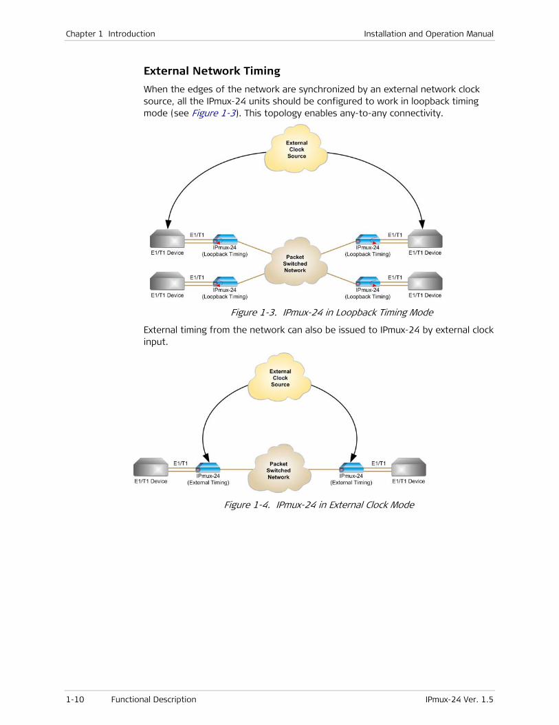
External Network Timing
When the edges of the network are synchronized by an external network clock source, all the IPmux-24 units should be configured to work in loopback timing mode (see Figure 1-3). This topology enables any-to-any connectivity.
Figure 1-3. IPmux-24 in Loopback Timing Mode
External timing from the network can also be issued to IPmux-24 by external clock input.
Figure 1-4. IPmux-24 in External Clock Mode

Installation and Operation Manual Chapter 1 Introduction
IPmux-24 Ver. 1.5 Functional Description 1-11
Adaptive Timing
When a common clock is not available on all the ends of the network, one of the IPmux-24 devices is configured to work in loopback timing, while the other IPmux-24 device is configured to work in adaptive timing (see Figure 1-5).
Figure 1-5. IPmux-24 in Adaptive Timing Mode
In leased line applications, the carrier does not know which side provides the source clock. To ensure correct clock distribution, IPmux-24 units working opposite each other can be both configured to adaptive clock.
As the clock is recovered twice, it is more sensitive to interferences introduced by the network.
Figure 1-6. IPmux-24 in Adaptive-Adaptive Timing Mode
Frame Format
Network encapsulation method depends on packet-switched network type (IP or MPLS) and pseudowire standard (TDMoIP, CESoPSN, SAToP or HDLCoPSN).
IP Encapsulation (MPLS and IP Networks)
The Ethernet frame sent by IPmux-24 is a UDP datagram that transfers E1/T1 payload bytes over IP over Ethernet (UDP payload + UDP header + IP header + Ethernet header). The UDP payload is equal to TDM bytes per frame (TDM bytes/frame configuration). Table 1-1 specifies the structure of the different headers, special fields, and the payload in the Ethernet packet.
CRC TDM Payload CW UDP IP ETH
Figure 1-7. TDMoIP Frame Structure
Note

Chapter 1 Introduction Installation and Operation Manual
1-12 Functional Description IPmux-24 Ver. 1.5
Table 1-1. TDMoIP Frame Structure
Field Length (Bytes) Field
7 Preamble
1 SFD
6 Destination MAC Address
6 Source MAC Address
2 Type
1 Vers/HLEN
1 Service Type
2 Total Length
2 Identification
1 Flags/Fragment Offset (most)
1 Fragment Offset (least)
1 Time to Live
1 Protocol
2 Header Checksum
4 Source IP Address
4 Destination IP Address
2 UDP Source Port
2 UDP Destination Port
2 UDP Message Length
2 UDP Checksum
4 Control Word
... Data
4 CRC
IP Layer
ETH Layer
UDP Layer
Data Layer
LLC Layer Note: IEEE 802.1p&Q VLAN Tagging (additional 4 bytes if enabled)
The UDP source port field is
used to transfer a destination
bundle number. See Note
below.
ETH Layer
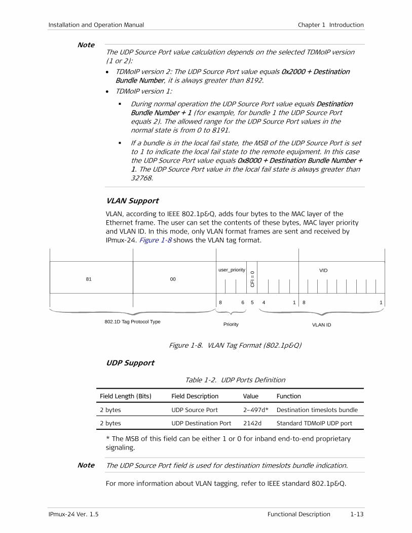
Installation and Operation Manual Chapter 1 Introduction
IPmux-24 Ver. 1.5 Functional Description 1-13
The UDP Source Port value calculation depends on the selected TDMoIP version (1 or 2):
• TDMoIP version 2: The UDP Source Port value equals 0x2000 + Destination Bundle Number, it is always greater than 8192.
• TDMoIP version 1:
During normal operation the UDP Source Port value equals Destination Bundle Number + 1 (for example, for bundle 1 the UDP Source Port equals 2). The allowed range for the UDP Source Port values in the normal state is from 0 to 8191.
If a bundle is in the local fail state, the MSB of the UDP Source Port is set to 1 to indicate the local fail state to the remote equipment. In this case the UDP Source Port value equals 0x8000 + Destination Bundle Number + 1. The UDP Source Port value in the local fail state is always greater than 32768.
VLAN Support
VLAN, according to IEEE 802.1p&Q, adds four bytes to the MAC layer of the Ethernet frame. The user can set the contents of these bytes, MAC layer priority and VLAN ID. In this mode, only VLAN format frames are sent and received by IPmux-24. Figure 1-8 shows the VLAN tag format.
802.1D Tag Protocol Type
81 00
user_priority
CFI
= 0 VID
8 6 5 4 1 8 1
Priority VLAN ID
Figure 1-8. VLAN Tag Format (802.1p&Q)
UDP Support
Table 1-2. UDP Ports Definition
Field Length (Bits) Field Description Value Function
2 bytes UDP Source Port 2–497d* Destination timeslots bundle
2 bytes UDP Destination Port 2142d Standard TDMoIP UDP port
* The MSB of this field can be either 1 or 0 for inband end-to-end proprietary signaling.
The UDP Source Port field is used for destination timeslots bundle indication.
For more information about VLAN tagging, refer to IEEE standard 802.1p&Q.
Note
Note

Chapter 1 Introduction Installation and Operation Manual
1-14 Functional Description IPmux-24 Ver. 1.5
MPLS Encapsulation (Ethernet and MPLS Networks)
Figure 1-13 and Table 1-3 illustrate TDMoMPLS frame structure.
CRC TDM Payload CW MPLS ETH
Figure 1-9. TDMoMPLS Frame Structure
Table 1-3. TDMoMPLS Frame Structure
Field Length (Bytes) Field
7 Preamble
1 SFD
6 Destination MAC Address
6 Source MAC Address
2 Type
20 Outer label
3 EXP
1 Stacking bit
8 TTL
20 Inner label
3 EXP
1 Stacking bit
8 TTL
4 Control Word
... Data
4 CRC
Payload Encapsulation
IPmux-24 supports the following payload encapsulation techniques: AAL1, CESoPSN and SAToP.
ETH Layer
LLC Layer Note: IEEE 802.1p&Q VLAN Tagging (additional 4 bytes if enabled)
ETH Layer
MPLS Layer (Bits)
The inner label field is used to
transfer a destination bundle
number.
Data Layer
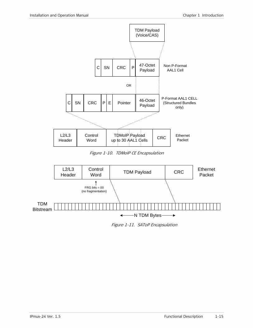
Installation and Operation Manual Chapter 1 Introduction
IPmux-24 Ver. 1.5 Functional Description 1-15
Non P-FormatAAL1 Cell
TDM Payload(Voice/CAS)
TDMoIP Payloadup to 30 AAL1 Cells
ControlWord
L2/L3Header
EthernetPacketCRC
P-Format AAL1 CELL(Structured Bundles
only)
OR
46-OctetPayloadPCRCSNC PointerE
47-OctetPayloadPCRCSNC
Figure 1-10. TDMoIP CE Encapsulation
L2/L3Header
ControlWord TDM Payload CRC Ethernet
Packet
N TDM Bytes
TDMBitstream
FRG bits = 00(no fragmentation)
Figure 1-11. SAToP Encapsulation

Chapter 1 Introduction Installation and Operation Manual
1-16 Functional Description IPmux-24 Ver. 1.5
4 25 254 254
Frame1
Frame2
FrameN
Frame 1
4 25 4 25 4 25
Frame 2 Frame N
L2/L3Header
ControlWord CRC Ethernet Packet
TDM Payload
FRG bits = 00(no fragmentation)
Figure 1-12. CESoPSN Encapsulation (E1, Bundle with Timeslots 4 and 25)
Packet Delay Variation
TDMoIP packets are transmitted by IPmux-24 at a constant rate towards the PSN (Packet-Switched Network). Packet Delay Variation is the deviation from the nominal time the packets are expected to arrive at the far end device. IPmux-24 has a jitter buffer that compensates for the deviation from the expected packet arrival time to ensure that the TDM traffic is sent to the TDM device at a constant rate.
The jitter buffer needs to be configured to compensate for the jitter level introduced by the PSN. If the PSN jitter level exceeds the configured jitter buffer size, underflow/overflow conditions occur, resulting in errors at the TDM side.
PDV
t
t
Packets Leaving IPmux-216
Packets Arriving
Figure 1-13. Packet Delay Variation
PDVT (Jitter) Buffer
IPmux-24 is equipped with a Packet DVT (Delay Variation Tolerance) buffer. The PDVT buffer or jitter buffer is filled by the incoming packets and emptied out to fill the TDM stream.
• A jitter buffer overrun usually occurs when IPmux-24 loses its clock synchronization
• A jitter buffer underrun occurs when no packets are received for more than the configured jitter buffer size, or immediately after an overrun.

Installation and Operation Manual Chapter 1 Introduction
IPmux-24 Ver. 1.5 Functional Description 1-17
When the first packet is received, or immediately after an underrun, the buffer is automatically filled with conditioning pattern up to the PDVT level in order to compensate for the underrun. Then, IPmux-24 processes the packet (packetization delay) and starts to empty out the jitter buffer to the TDM side. See Figure 1-14 for the illustration of the PDVT buffer operation.
The PDVT (jitter) buffer is designed to compensate for network delay variation of up to 180 msec.
Packets arriving from the PSN side are stored in the jitter buffer before being transmitted to the TDM side, adding a delay to the TDM traffic. The delay time equals to the PDVT size configured by the user.
PDVT (Jitter) Buffer Depth
Normal Operation(No PDV)
Maximum Jitter Buffer Size(2 PDVT + 2 PCT + 1 msec)
PDVT Buffer + Packet Creation Time
Figure 1-14. Jitter Buffer Operation
The maximum jitter buffer size is 2 × PDVT + PCT + 1 msec.
Packet Creation Time (PCT)
When IPmux-24 builds a frame, a packetization delay is introduced. The packet creation time is different for the different payload encapsulation methods. It is calculated according to the following formulas:
TDMoIP
PCT (ms) = TS
0.125N 47 ××
Where:
N = 48
ebytes/framTDM
TS = number of assigned timeslots (in unframed mode= 32 for E1, 24 for T1)
For a bundle that contains a few timeslots (i.e. 1 to 3), the recommended number of TDM bytes/frame is 48 in order to prevent excessive PCT.
CESoPSN
PCT (ms) = N × 0.125
Where:
N = Number of TDM frames in packet
Note

Chapter 1 Introduction Installation and Operation Manual
1-18 Functional Description IPmux-24 Ver. 1.5
SAToP
PCT (ms) = TS0.125N ×
N – Number of TDM bytes in packet
TS – Number of timeslots in one frame (32 for E1 or 24 for T1)
Round Trip Delay
The voice path round-trip delay is a function of all connections and network parameters.
(±2 msec) RT Delay(msec) = 2 × (PCT + Jitter Buffer Level) + network round trip delay
Ethernet Throughput
Increasing payload size reduces the ratio between the TDMoIP/IP/Ethernet header segment in the packet and the payload, thus reducing the total Ethernet throughput.
On the other hand, packetization delay is increased; this contributes to a higher end-to-end delay. This effect can be small and negligible when a full E1 (or many timeslots) are transferred, but can be very significant when few timeslots are transferred.
Configuring the TDM bytes per frame (TDM bytes/frame) parameter has impact on the Ethernet throughput (bandwidth or traffic traveling through the Ethernet). This parameter controls the number of TDM bytes encapsulated in one frame.
The TDM bytes/frame parameter can be configured to N × 48 bytes where N is an integer between 1 and 30.
To calculate Ethernet throughput as a function of TDM bytes/frame:
Ethernet load (bps) = [(frame overhead (bytes) + TDM bytes/frame) × 8] × frames/second
Frame overhead (IP) = Ethernet overhead + IP overhead = 46 bytes
Frame overhead (MPLS) = Control Word + MPLS overhead + Ethernet overhead = 22 bytes
The frame overhead does not include:
• Preamble field: 7 bytes
• SFD field: 1 byte
• Interframe gap: 12 bytes
• VLAN field (when used): 4 bytes.
Frame/second = Unframed: 5447/n for a full E1
4107/n for a full T1 Framed: 8000 × k/(46.875 × n)
Note

Installation and Operation Manual Chapter 1 Introduction
IPmux-24 Ver. 1.5 Functional Description 1-19
Where k = number of assigned timeslots
Where n = 48
ebytes/framTDM
The maximum Ethernet throughput is calculated by:
PCT1
bits 8)
bytes) (in size frame
( ××+++4444444 34444444 21
payloadoverhead frameCW VLAN
Where:
• VLAN is an optional field: if enabled it adds 4 bytes to the frame overhead
• CW = control word (4 bytes)
• payload = number of TDM bytes in frame, (48, 96, 144, 192, … 1440)
• frame overhead = size of 46 bytes, include MAC, LLC, IP and UDP layer
The result is in bits per second (bps).
Pseudowire OAM
OAM connectivity is used to detect a valid connection (the remote IPmux will confirm it recognizes the connection and that it is enabled). It prevents flooding by a handshake. The control packets are run over a unique bundle number that is used for this purpose. The control packets have the same packet overhead as the traffic. The control packet uses the TDMoIP UDP number. OAM connectivity can be enabled or disabled.
For control packets, the UDP checksum is neither calculated nor checked.
End-to-End Alarm Generation
An end-to-end alarm generation mechanism exists in IPmux-24 to facilitate the following alarms:
• Unframed – AIS is transmitted toward the near-end PBX in event of far-end LOS, AIS
• Framed – Timeslot/CAS configurable alarm pattern is transmitted toward the near-end PBX in event of far-end LOS, LOF, AIS.
Trail-Extended Mode
To enhance fault condition reporting capabilities, remote IPmux-24 transfers RDI, LOS, LOF and AIS conditions received from the remote E1 device to the local E1 device (see Figure 1-15).
Figure 1-15. Fault Indication Transfer
Note
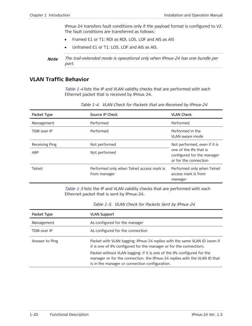
Chapter 1 Introduction Installation and Operation Manual
1-20 Functional Description IPmux-24 Ver. 1.5
IPmux-24 transfers fault conditions only if the payload format is configured to V2. The fault conditions are transferred as follows:
• Framed E1 or T1: RDI as RDI, LOS, LOF and AIS as AIS
• Unframed E1 or T1: LOS, LOF and AIS as AIS.
The trail-extended mode is operational only when IPmux-24 has one bundle per port.
VLAN Traffic Behavior
Table 1-4 lists the IP and VLAN validity checks that are performed with each Ethernet packet that is received by IPmux-24.
Table 1-4. VLAN Check for Packets that are Received by IPmux-24
Packet Type Source IP Check VLAN Check
Management Performed Performed
TDM over IP Performed Performed in the
VLAN-aware mode
Receiving Ping Not performed Not performed, even if it is
one of the IPs that is
configured for the manager
or for the connection
ARP Not performed
Telnet Performed only when Telnet access mark is
from manager
Performed only when Telnet
access mark is from
manager
Table 1-5 lists the IP and VLAN validity checks that are performed with each Ethernet packet that is sent by IPmux-24.
Table 1-5. VLAN Check for Packets Sent by IPmux-24
Packet Type VLAN Support
Management As configured for the manager
TDM over IP As configured for the connection
Answer to Ping Packet with VLAN tagging: IPmux-24 replies with the same VLAN ID (even if
it is one of IPs configured for the manager or for the connection).
Packet without VLAN tagging: if it is one of the IPs configured for the
manager or for the connection, the IPmux-24 replies with the VLAN ID that
is in the manager or connection configuration.
Note

Installation and Operation Manual Chapter 1 Introduction
IPmux-24 Ver. 1.5 Functional Description 1-21
Packet Type VLAN Support
ARP initiated by IPmux-24 No VLAN value unless it is to one of the managers or the connection’s IP
address Telnet
Ping initiated by IPmux-24
Bridge
The bridge operates in the VLAN-aware and VLAN-unaware modes. In the VLAN-aware mode, the bridge supports up to 64 VLANs. Learning and filtering can be enabled or disabled. Static MAC addresses are stored in the MAC table. The size of the MAC table is 8128 addresses. The bridge can handle frames of up to 1632 bytes.
The unit can append additional VLAN tag (provider VLAN) at the user port ingress and remove it at the network port ingress. The provider VLAN includes provider VID and priority (VLAN stacking).
Double Host
IPmux-24 includes two different hosts:
• Management host for handling the management traffic
• PW host for handling the pseudowire traffic.
Each host has a separate MAC address.
Ring Topology
Ring topology, implemented by means of the RAD-proprietary protocol (RFER), provides protection for the Ethernet transmission path, and is especially suited for MAN and dark fiber applications.
When the ring is enabled, the data is propagated between the nodes either ”clockwise” or ”counterclockwise”. Because of the Ethernet protocol characteristics, actually the ring cannot be closed: a pair of adjacent nodes on the ring keep the ring open by disconnecting an arbitrary ring segment, thereby preventing frames from making a full round trip.
Figure 1-16 shows a basic ring topology; the arrow shows the path followed by frames exchanged between ring nodes A and D during normal operation, assuming that the blocked segment is between nodes A and D.

Chapter 1 Introduction Installation and Operation Manual
1-22 Functional Description IPmux-24 Ver. 1.5
Figure 1-16. Basic Ring Redundancy Topology – Data Flow during Normal Operation
If a segment, for example, the segment between nodes B and C, breaks (fails), the ring mechanism automatically moves the blocking nodes to the ends of the failed segment and reconnects the previously disconnected segment.
The new path of the frames is shown in Figure 1-17. Therefore, full connectivity is restored for any single point of failure. For PW traffic, the redundancy mechanism ensures that this change takes effect within 50 msec.
Figure 1-17. Basic Ring Redundancy Topology – Data Flow after Recovery from Segment Failure
The method used to achieve fast recovery is based on the use of VLAN tagging. This approach enables adjacent nodes on the ring to exchange protocol messages that check the connectivity, and multicast ring open messages to all the nodes in case a fault is detected on a segment. Note however that this means the ring VLAN ID cannot be used for other traffic.
Two VLANs are used by the ring mechanism: one for the multicast messages (Ring Reject, Ring Open) and one for unicast messages (Link KeepAlive, Ring Detect, Ring Closed).
VLANs reserved for the ring messages cannot be used for other traffic.
The fast redundancy protection available to the PW traffic within the ring can be extended to other equipment: such equipment is connected to the USER port of the IPmux-24 devices, and therefore its traffic is not processed by IPmux-24: it only passes to the network through the IPmux-24 network ports.
The protected addresses are destination addresses for traffic connected to IPmux-24 through the user port: this may be traffic from another IPmux-24 device, or from any other type of equipment using IPmux-24 to connect to remote sites.
Note

Installation and Operation Manual Chapter 1 Introduction
IPmux-24 Ver. 1.5 Functional Description 1-23
Ring topology is configured via an ASCII terminal. SNMP management stations display only ring status information.
Management
Setup, monitoring and diagnostics tests can be performed using one of the following methods:
• Local management via ASCII terminal connected to the V.24/RS-232 DCE control port.
• Remote management via the network or user ports using Telnet SSH, Web, Secured Web (HTTPS) using Web terminal, or RADview, RAD’s SNMP-based management system. IPmux-24 supports the SNMP version 3 entity, providing secure access to the device by authenticating and encrypting packets transmitted over the network.
Security
To ensure client-server communication privacy and correct user authentication, IPmux-24 supports the security protocols listed below:
• RADIUS (client authentication only)
• SSL for Web-based management application
• SSH for Secure Shell communication session
• SNMPv3.
QoS
IPmux-24 supports traffic prioritization and rate limitation.
Traffic Classification and Prioritization
IPmux-24 provides four priority queues for each user port. The traffic can be classified and mapped into the priority queues according to the VLAN priority, DSCP, IP Precedence or per port basis. In VLAN-unaware mode TDM traffic receives the highest priority automatically.
Rate Limitation
IPmux-24 supports an egress and ingress rate limitation per network and user ports.
L2CP Handling
Each Ethernet port can be configured to tunnel the Layer-2 control frames across the network, to peer supported protocols (OAM.ah) or to discard the L2CP frames.
Note

Chapter 1 Introduction Installation and Operation Manual
1-24 Technical Specifications IPmux-24 Ver. 1.5
1.4 Technical Specifications
E1 Interface Number of Ports 1, 2 or 4
Compliance ITU-T Rec. G.703, G.704, G.706, G.732, G.823
Data Rate 2.048 Mbps
Line Code HDB3
Framing Unframed, framed, multiframe; with or without CRC-4
Signaling CAS, CCS (transparent)
Line Impedance Balanced: 120Ω; unbalanced: 75Ω
Signal Levels Receive: 0 to -36 dB LTU (long haul) 0 to -10 dB DSU (short haul)
Transmit pulse amplitude, balanced: ±3V ±10% Transmit pulse amplitude, unbalanced: ±2.37V ±10%
Jitter Performance As per ITU-T G.823
Connector Balanced: RJ-45
Unbalanced: Two BNC coax (via an adapter cable)
T1 Interface Number of Ports 1, 2 or 4
Compliance ANSI T1.403, AT&T TR-62411, ITU-T Rec. G.703, G.704, G.824
Data Rate 1.544 Mbps
Line Code B8ZS, B7ZS, AMI
Framing Unframed, SF, ESF
Signaling CAS (robbed bit), CCS (transparent)
Line Impedance Balanced: 100Ω
Signal Levels Receive: 0 to -36 dB
Transmit pulse amplitude: ±3V ±20%; 0 dB, -7.5 dB, -15 dB, -22 dB (CSU), user-selectable
±2.7V ±10%, 0 to 655 feet, (DSU), user-selectable
Jitter Performance As per AT&T TR-62411, G.824 (for internal, loopback and external clock modes)

Installation and Operation Manual Chapter 1 Introduction
IPmux-24 Ver. 1.5 Technical Specifications 1-25
Connector RJ-45
Ethernet Interface
Compliance IEEE 802.3, 802.3u, 802.1p&Q
Port Combinations 3 fiber optic SFPs
2 fiber optic SFPs + 1 UTP
1 fiber optic SFP + 2 UTPs
3 UTPs
Interfaces 1000BaseX, 100BaseFx, 1000BaseT SFPs or built-in 10/100BaseT
Frame Size 1632 bytes max
Fiber Optic Specifications
See the SFP Transceivers data sheet
Timing Transmit • Internal
• External input or output via dedicated connector: E1/T1 or 2048/1544 kHz squarewave (RS-422 electrical levels)
• Loopback
• Adaptive
IPmux-24/A Adaptive Clock
Frequency Accuracy Better than 16 ppb and G.823 synchronization interface requirements (clause 6), when locked to a PRC (stratum 1) or SSU (stratum 2) clock
Frequency Accuracy in Holdover
±16 ppb ±1 ppb of aging per day
Pseudowire Number of Connections
Up to 64
Standard Compliance
TDM:
• IETF: RFC 4553 (SAToP), RFC 5087 (TDMoIP), RFC 5086 (CESoPSN)
• ITU-T: Y.1413 (TDMoIP)
• MFA: IA 4.0
• MEF: 9, 14 (EPL certified)
HDLC:
• IETF: IETF RFC 4618 (excluding clause 5.3 – PPP) and RFC 5087
Jitter Buffer Size • 0.5–180 msec (unframed) with 0.1 msec granularity
• 2.5–180 msec (framed) with 0.5 msec granularity

Chapter 1 Introduction Installation and Operation Manual
1-26 Technical Specifications IPmux-24 Ver. 1.5
Management Methods • SNMPv1, SNMPv3
• Telnet
• RADview Service Center TDMoIP (ordered separately)
• ASCII terminal via V.24 (RS-232) DCE port
Diagnostics Loopbacks • E1/T1 local loopback
• E1/T1 remote loopback
• T1 Facility Type 1 (FAC1) inband loopback
Statistics E1/T1 As per G.826 and RFC 2495
Ethernet As per RFC 2819
Receive Buffer Indication
Overflow, underflow, sequence error
Alarm Relay Dry Contact Via pin 6, pin 7 and pin 8 of the EXT CLK connector (RJ-45)
Indicators General PWR (green) – Power
ALM (red/yellow) – Alarm status
SD (red/green) – External clock status
E1 E1 SYNC (red/green) – E1 synchronization
T1 T1 SYNC (red/green) – T1 synchronization
Ethernet LINK/ACT (green) – Link/activity status
Power AC/DC Source 100–240 VAC, 50/60 Hz or 48/60 VDC nominal (40 to 72 VDC)
DC Source 24 VDC nominal (18 to 36 VDC)
Power Consumption 13W max
Physical Height 47 mm (1.8 in)
Width 215 mm (8.7 in)
Depth 147 mm (5.8 in)
Weight 0.7 kg (1.5 lb)
Environment Temperature IPmux-24: 0°C to 50°C (32°C to 122°F)
IPmux-24/H: -30 to 65°C (-22 to 149°F)
Humidity Up to 90%, non-condensing

IPmux-24 Ver. 1.5 Package Contents 2-1
Chapter 2
Installation and Setup
2.1 Introduction
This chapter describes installation and setup procedures for the IPmux-24 unit.
After installing the unit, refer to Chapter 3 for the operating instructions.
If a problem is encountered, refer to Chapter 6 for test and diagnostic instructions.
Internal settings, adjustment, maintenance, and repairs may be performed only by a skilled technician who is aware of the hazards involved.
Always observe standard safety precautions during installation, operation, and maintenance of this product.
2.2 Site Requirements and Prerequisites
AC-powered IPmux-24 units should be installed within 1.5m (5 ft) of an easily-accessible grounded AC outlet capable of furnishing the voltage in accordance with IPmux-24 nominal supply voltage.
DC-powered IPmux-24 units require a 24 or 48 VDC power source, which must be adequately isolated from the main supply.
Allow at least 90 cm (36 in) of frontal clearance for operating and maintenance accessibility. Allow at least 10 cm (4 in) clearance at the rear of the unit for signal lines and interface cables.
The ambient operating temperature of IPmux-24 must be 0°C to 50°C (32°C to 122°F), at a relative humidity of up to 90%, non-condensing.
2.3 Package Contents
The IPmux-24 package includes the following items:
• One IPmux-24 unit
• Matching SFP module (if ordered)
• AC power cord
• AC/DC adapter plug
• CBL-RJ45/2BNC/E1/X adapter cable for unbalanced E1 interface (if ordered)
• CBL-DB9F-DB9M-STR control port cable (if ordered)
Warning

Chapter 2 Installation and Setup Installation and Operation Manual
2-2 Mounting the Unit IPmux-24 Ver. 1.5
• RM-35/P1 rack mount kit for mounting one IPmux-24 unit (if ordered)
• RM-35/P2 rack mount kit for mounting two IPmux-24 units (if ordered)
• WM-35 wall mount kit for IPmux-24 (if ordered).
2.4 Equipment Needed
IPmux-24 is a standalone unit, designed for desktop or bench installation and is delivered fully assembled. No provisions are made for bolting the unit to a tabletop.
Mounting IPmux-24 in a 19-inch rack, however, requires a 3 mm Phillips screwdriver and an RM-35 kit. For the rack installation instructions, refer to the Rack Mounting Kit for 19-inch Racks guide that comes with the RM kit.
Power Cable
AC-powered IPmux-24 is equipped with an appropriate power cord (country or region dependent) to be connected from the mains to the power socket of the hot-swappable power unit.
DC-powered IPmux-24 is equipped with an appropriate DC connection kit, which should be used for preparing the DC cable connection.
Interface Cables
Refer to the following table to determine what cables and connectors are required for installation. Appendix A specifies the wiring of all connector pinouts.
Table 2-1. Required Interface Cables
Interface Cable Type
Control terminal DB-9 to DB-9, RS-232/V.24 compliant cable for
ASCII-based terminal control
Ethernet • Electrical: Cat. 5, RJ-45 to RJ-45, IEEE 802.3 compliant
cable
• Fiber optic: Fiber optic cable that matches the
ordered interface type.
E1/T1 • Balanced: Cat. 5, RJ-45 to RJ-45 cable
• Unbalanced: CBL-RJ45/2BNC/E1/X adapter cable
2.5 Mounting the Unit
IPmux-24 is designed for installation as a desktop unit. It can also be mounted in a 19" rack or on a wall.
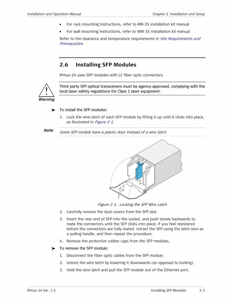
Installation and Operation Manual Chapter 2 Installation and Setup
IPmux-24 Ver. 1.5 Installing SFP Modules 2-3
• For rack mounting instructions, refer to RM-35 installation kit manual
• For wall mounting instructions, refer to WM-35 installation kit manual
Refer to the clearance and temperature requirements in Site Requirements and Prerequisites.
2.6 Installing SFP Modules
IPmux-24 uses SFP modules with LC fiber optic connectors.
Third-party SFP optical transceivers must be agency-approved, complying with the local laser safety regulations for Class 1 laser equipment.
To install the SFP modules:
1. Lock the wire latch of each SFP module by lifting it up until it clicks into place, as illustrated in Figure 2-1.
Some SFP models have a plastic door instead of a wire latch.
Figure 2-1. Locking the SFP Wire Latch
2. Carefully remove the dust covers from the SFP slot.
3. Insert the rear end of SFP into the socket, and push slowly backwards to mate the connectors until the SFP clicks into place. If you feel resistance before the connectors are fully mated, retract the SFP using the latch wire as a pulling handle, and then repeat the procedure.
4. Remove the protective rubber caps from the SFP modules.
To remove the SFP module:
1. Disconnect the fiber optic cables from the SFP module.
2. Unlock the wire latch by lowering it downwards (as opposed to locking).
3. Hold the wire latch and pull the SFP module out of the Ethernet port.
Note
Warning
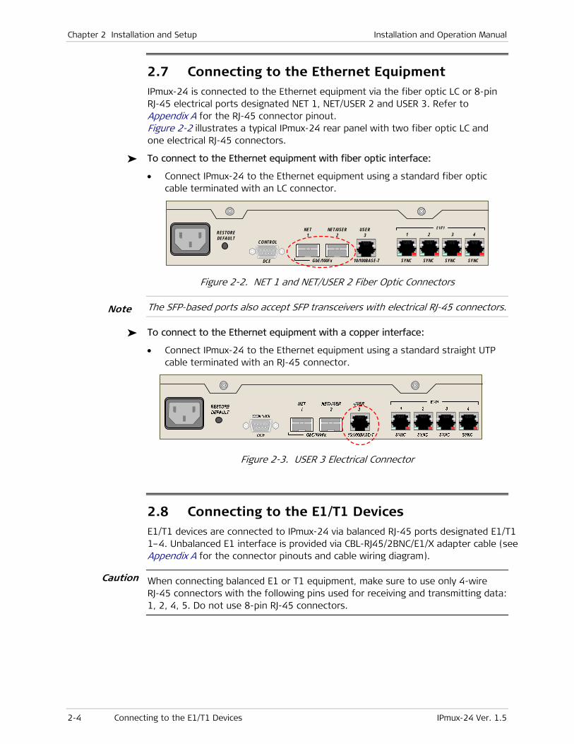
Chapter 2 Installation and Setup Installation and Operation Manual
2-4 Connecting to the E1/T1 Devices IPmux-24 Ver. 1.5
2.7 Connecting to the Ethernet Equipment IPmux-24 is connected to the Ethernet equipment via the fiber optic LC or 8-pin RJ-45 electrical ports designated NET 1, NET/USER 2 and USER 3. Refer to Appendix A for the RJ-45 connector pinout. Figure 2-2 illustrates a typical IPmux-24 rear panel with two fiber optic LC and one electrical RJ-45 connectors.
To connect to the Ethernet equipment with fiber optic interface:
• Connect IPmux-24 to the Ethernet equipment using a standard fiber optic cable terminated with an LC connector.
RESTOREDEFAULT
CONTROL
DCE GbE/100Fx
NET1
NET/USER2
USER3
10/100BASE-T
1
SYNC
2 3 4
SYNC SYNC SYNC
E1/T1
Figure 2-2. NET 1 and NET/USER 2 Fiber Optic Connectors
The SFP-based ports also accept SFP transceivers with electrical RJ-45 connectors.
To connect to the Ethernet equipment with a copper interface:
• Connect IPmux-24 to the Ethernet equipment using a standard straight UTP cable terminated with an RJ-45 connector.
Figure 2-3. USER 3 Electrical Connector
2.8 Connecting to the E1/T1 Devices E1/T1 devices are connected to IPmux-24 via balanced RJ-45 ports designated E1/T1 1–4. Unbalanced E1 interface is provided via CBL-RJ45/2BNC/E1/X adapter cable (see Appendix A for the connector pinouts and cable wiring diagram).
When connecting balanced E1 or T1 equipment, make sure to use only 4-wire RJ-45 connectors with the following pins used for receiving and transmitting data: 1, 2, 4, 5. Do not use 8-pin RJ-45 connectors.
Caution
Note
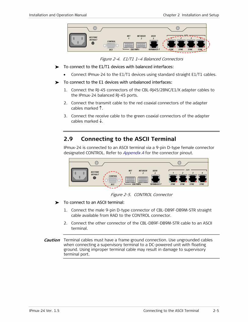
Installation and Operation Manual Chapter 2 Installation and Setup
IPmux-24 Ver. 1.5 Connecting to the ASCII Terminal 2-5
RESTOREDEFAULT
CONTROL
DCE GbE/100Fx
NET1
NET/USER2
USER3
10/100BASE-T
1
SYNC
2 3 4
SYNC SYNC SYNC
E1/T1
Figure 2-4. E1/T1 1–4 Balanced Connectors
To connect to the E1/T1 devices with balanced interfaces:
• Connect IPmux-24 to the E1/T1 devices using standard straight E1/T1 cables.
To connect to the E1 devices with unbalanced interfaces:
1. Connect the RJ-45 connectors of the CBL-RJ45/2BNC/E1/X adapter cables to the IPmux-24 balanced RJ-45 ports.
2. Connect the transmit cable to the red coaxial connectors of the adapter cables marked ↑.
3. Connect the receive cable to the green coaxial connectors of the adapter cables marked ↓.
2.9 Connecting to the ASCII Terminal IPmux-24 is connected to an ASCII terminal via a 9-pin D-type female connector designated CONTROL. Refer to Appendix A for the connector pinout.
RESTOREDEFAULT
CONTROL
DCE GbE/100Fx
NET1
NET/USER2
USER3
10/100BASE-T
1
SYNC
2 3 4
SYNC SYNC SYNC
E1/T1
Figure 2-5. CONTROL Connector
To connect to an ASCII terminal:
1. Connect the male 9-pin D-type connector of CBL-DB9F-DB9M-STR straight cable available from RAD to the CONTROL connector.
2. Connect the other connector of the CBL-DB9F-DB9M-STR cable to an ASCII terminal.
Terminal cables must have a frame ground connection. Use ungrounded cables when connecting a supervisory terminal to a DC-powered unit with floating ground. Using improper terminal cable may result in damage to supervisory terminal port.
Caution
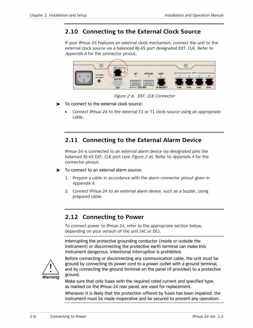
Chapter 2 Installation and Setup Installation and Operation Manual
2-6 Connecting to Power IPmux-24 Ver. 1.5
2.10 Connecting to the External Clock Source
If your IPmux-24 features an external clock mechanism, connect the unit to the external clock source via a balanced RJ-45 port designated EXT. CLK. Refer to Appendix A for the connector pinout.
Figure 2-6. EXT. CLK Connector
To connect to the external clock source:
• Connect IPmux-24 to the external E1 or T1 clock source using an appropriate cable.
2.11 Connecting to the External Alarm Device
IPmux-24 is connected to an external alarm device via designated pins the balanced RJ-45 EXT. CLK port (see Figure 2-6). Refer to Appendix A for the connector pinout.
To connect to an external alarm source:
1. Prepare a cable in accordance with the alarm connector pinout given in Appendix A.
2. Connect IPmux-24 to an external alarm device, such as a buzzer, using prepared cable.
2.12 Connecting to Power To connect power to IPmux-24, refer to the appropriate section below, depending on your version of the unit (AC or DC).
Interrupting the protective grounding conductor (inside or outside the instrument) or disconnecting the protective earth terminal can make this instrument dangerous. Intentional interruption is prohibited.
Before connecting or disconnecting any communication cable, the unit must be ground by connecting its power cord to a power outlet with a ground terminal, and by connecting the ground terminal on the panel (if provided) to a protective ground.
Make sure that only fuses with the required rated current and specified type, as marked on the IPmux-24 rear panel, are used for replacement.
Whenever it is likely that the protection offered by fuses has been impaired, the instrument must be made inoperative and be secured to prevent any operation.
Warning

Installation and Operation Manual Chapter 2 Installation and Setup
IPmux-24 Ver. 1.5 Connecting to Power 2-7
Refer also to the sections describing connections of AC and DC mains at the beginning of the manual.
Connecting AC Power
AC power is supplied to IPmux-24 through the 1.5m (5 ft) standard power cable terminated by a standard 3-prong plug. The cable is supplied with the unit according to the number of ordered power supplies.
To connect AC power:
1. Verify that the AC outlet is grounded properly. Ensure that the supply voltage is in the range 100 VAC to 240 VAC.
2. Connect the power cable to the rear panel connector first and then to the AC mains outlet.
Connecting DC Power
DC power is supplied via an AC/DC adapter plug provided with the unit.
To connect DC power:
• Refer to the DC power supply connection supplement for instructions how to wire the DC adapters. The DC supplement is provided at the end of the manual.
Note

Chapter 2 Installation and Setup Installation and Operation Manual
2-8 Connecting to Power IPmux-24 Ver. 1.5

IPmux-24 Ver. 1.5 Indicators 3-1
Chapter 3
Operation This chapter:
• Provides a detailed description of the front panel controls and indicators and their functions
• Explains power-on and power-off procedures
• Provides instructions for configuration using a terminal connected to the IPmux-24 control port
• Provides instructions for configuration using a Web browser
• Illustrates the management menus.
For a detailed explanation of parameters on the menus, see Chapter 4.
3.1 Turning On the Unit
To turn on IPmux-24:
• Connect the power cord to the mains.
Once it is powered up, IPmux-24 operates automatically. IPmux-24 requires no operator attention once installed, with the exception of occasional monitoring of front panel indicators. Intervention is only required when IPmux-24 must be configured to its operational requirements, or diagnostic tests are performed.
3.2 Indicators
The unit's LEDs are located on the front and rear panels (see Figure 3-1). Table 3-1 lists the functions of the IPmux-24 LED indicators.
RAD
IPmux-24
PWR TST 1 2 3
ETHLINK/ACT
Figure 3-1. IPmux-24 Front Panel

Chapter 3 Operation Installation and Operation Manual
3-2 Default Settings IPmux-24 Ver. 1.5
Table 3-1. IPmux-24 LEDs and Controls
Name Type Function Location
PWR Green LED ON – Power is ON Front panel
TST/ALM Red/yellow
LED
ON (red) – Active alarm is stored in the log file
ON (yellow) – An alarm is present in the log file
OFF – No alarms are stored in the log file
Blinks (red) – Active alarm is stored in the log file and a test is
active
Blinks (red) – An alarm is present in the log file and a test is
active or only a test is active
Front panel
E1 SYNC Red/green
LED
ON (green) – E1 link is synchronized
ON (red) – E1 link has lost synchronization
OFF – E1 link is disabled
Rear panel
T1 SYNC Red/green
LED
ON (green) – T1 link is synchronized
ON (red) – T1 link has lost synchronization
OFF – T1 link is disabled
Rear panel
ETH
LINK/ACT 1
Green LED ON – Network Ethernet link is OK
Blinks – Data is being transmitted or received on the network
Ethernet link
Front panel
ETH
LINK/ACT 2
Green LED ON – User Ethernet link 1 is OK
Blinks – Data is being transmitted or received on the user
Ethernet link 1
Front panel
ETH
LINK/ACT 3
Green LED ON – User Ethernet link 2 is OK
Blinks – Data is being transmitted or received on the user
Ethernet link 2
Front panel
SD Red/green
LED
ON (green) – IPmux-24 is configured to external clock and valid
clock input is detected
ON (red) – IPmux-24 is configured to external clock and no
valid clock input is detected
OFF – IPmux-24 is not configured to external clock or the unit
is off
Rear panel
RESTORE
DEFAULT
Button Restores default values Rear panel
3.3 Default Settings
The following table lists the default settings of the IPmux-24 configuration parameters.
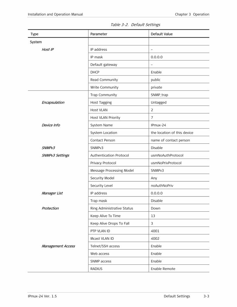
Installation and Operation Manual Chapter 3 Operation
IPmux-24 Ver. 1.5 Default Settings 3-3
Table 3-2. Default Settings
Type Parameter Default Value
System
Host IP IP address –
IP mask 0.0.0.0
Default gateway –
DHCP Enable
Read Community public
Write Community private
Trap Community SNMP_trap
Encapsulation Host Tagging Untagged
Host VLAN 2
Host VLAN Priority 7
Device Info System Name IPmux-24
System Location the location of this device
Contact Person name of contact person
SNMPv3 SNMPv3 Disable
SNMPv3 Settings Authentication Protocol usmNoAuthProtocol
Privacy Protocol usmNoPrivProtocol
Message Processing Model SNMPv3
Security Model Any
Security Level noAuthNoPriv
Manager List IP address 0.0.0.0
Trap mask Disable
Protection Ring Administrative Status Down
Keep Alive Tx Time 13
Keep Alive Drops To Fall 3
PTP VLAN ID 4001
Mcast VLAN ID 4002
Management Access Telnet/SSH access Enable
Web access Enable
SNMP access Enable
RADIUS Enable Remote

Chapter 3 Operation Installation and Operation Manual
3-4 Default Settings IPmux-24 Ver. 1.5
Type Parameter Default Value
RADIUS Parameters Server IP Address 0.0.0.0
Shared Secret –
Number of Retries 1
Timeout 1
Authentication Port –
Accounting Port –
Alarm Trap Mask Alarm ID 1
Trap Status Masked
User Access User name su
Permission Full control
Access All
Control Port Baud rate (bps) 115200
System Clock Master clock Rx clock
Master source Channel 1
Fall back clock Internal
Fall back source Channel 1
Physical Layer Administrative status Up
E1 Transmit clock source Adaptive
Source clock quality Other/unknown
Trail mode Termination
Line type Framed G.704
Line interface DSU
Idle code 7E
Send upon fail OOS code
OOS code FF
OOS signaling Space
Mark signaling code D
Space signaling code 1
Ethernet network type WAN
T1 Administrative status Up
Transmit clock source Adaptive
Source clock quality Other/unknown
Rx sensitivity Short haul

Installation and Operation Manual Chapter 3 Operation
IPmux-24 Ver. 1.5 Default Settings 3-5
Type Parameter Default Value
Trail mode Termination
Line type ESF
Line code B8ZS
Line interface DSU
Line BildOut 0 dB
Line length 0–133
Restoration time Fast (1 Second)
Idle code 7E
OOS code 7F
Signaling mode None
OOS signaling Space
Mark signaling code D
Space signaling code 1
Send upon fail OOS code
Ethernet network type WAN
Ethernet Administrative status Up
Auto negotiation Disable for fiber optic interface
Enable for copper interface
Max Capability Advertised 100baseT Full Duplex
Speed & Duplex 10baseT Half Duplex
Connection Bundle ID 1
PW type TDMoIP CE
PSN type UDP/IP
PW Host IP IP address –
IP mask 0.0.0.0
Default next hop –
Host Tagging Untagged
Host VLAN ID 2
Host VLAN Priority 7
Bundle Connection Destination IP address –
Next hop –
IP TOS 0
Connection status Enable

Chapter 3 Operation Installation and Operation Manual
3-6 Default Settings IPmux-24 Ver. 1.5
Type Parameter Default Value
Destination bundle 1
TDM bytes in frame 1
Payload format V2
Far end type E1 or T1 (ESF)
OAM connectivity Enable
Jitter buffer 3.0
Sensitive Data
OOS mode Tx OOS
VLAN tagging Disable
VLAN ID 2
VLAN Priority 7
PSN Type MPLS/ETH
Outbound label tagging Disable
Next Hop Type IP
Bridge VLAN Mode Unaware
Forwarding Mode Filter
Aging time 300
Bridge Port Ingress Filtering Enable
Accept Frame Type All
L2CP Handling Tunnel
Port VID 1
Default Priority Tag 0
Tag Handling None
QoS
Classification Network ETH1 802.1p
Network/User ETH2 802.1p
User ETH3 802.1p
TDM PW 802.1p
Rate Limitation (Egress) Rate limitation No Limit
Rate Limitation (Ingress) Rate limitation No Limit
Burst size 12
Limit Packet Type All
Installation and Operation Manual Chapter 3 Operation
IPmux-24 Ver. 1.5 Configuration and Management Alternatives 3-7
3.4 Configuration and Management Alternatives
If required, IPmux-24 can be reconfigured. The IPmux-24 configuration and monitoring operations are performed using any of the following tools:
• ASCII terminal connected to supervisory port
• Web-based management system, using a Web browser running on a PC connected to the network
• RADview, RAD’s SNMP-based management system with a graphical user interface. See RADview SC/TDMoIP User's Manual for details
• Third-party SNMP-based management systems.
Detailed configuration procedures are given in Chapter 4.
The following functions are supported by the IPmux-24 management software:
• Viewing system information
• Modifying configuration and mode of operation, including setting system default values
• Monitoring IPmux-24 performance
• Initiating diagnostic tests
• Uploading and downloading software and configuration files.
Working with Terminal
IPmux-24 includes a V.24/RS-232 asynchronous DCE port, designated CONTROL and terminated in a 9-pin D-type female connector. The control port continuously monitors the incoming data stream and immediately responds to any input string received through this port.
The IPmux-24 control port can be configured to communicate at the following rates: 9.6, 19.2, 38.4, 57.6 or 115.2 kbps.
To start a terminal control session:
1. Make sure all IPmux-24 cables and connectors are properly connected.
2. Connect IPmux-24 to a PC equipped with an ASCII terminal emulation application (for example, Windows Hyper Terminal or Procomm).
3. Turn on the control terminal PC and set its port parameters to 115.2 kbps, 8 bits/character, 1 stop bit, no parity. Set the terminal emulator to ANSI VT100 emulation (for optimal view of system menus).
Login
To prevent unauthorized modification of the operating parameters, IPmux-24 supports three access levels:
• Superuser can perform all the activities supported by the IPmux-24 management facility.
• Users have read-only access, they cannot change any settings.

Chapter 3 Operation Installation and Operation Manual
3-8 Configuration and Management Alternatives IPmux-24 Ver. 1.5
• Techs (technicians) – read-only access, but the technicians are allowed to reset the unit, set its parameters to defaults and use TFTP download/upload.
The su, user and tech are permanent users, they cannot be removed from the authorization database. The su level users can define new dynamic users and assign access levels (su, user or tech) to them.
To enter as a superuser:
1. Enter su for user name.
2. Enter 1234 for password.
To enter as a user:
1. Enter user for user name.
2. Enter 1234 for password.
To enter as a technician:
1. Enter tech for user name.
2. Enter 1234 for password.
Choosing Options
How to use the terminal to perform a desired activity:
• To select a menu item, type the corresponding line number and then press <Enter>. This will either …
… display a submenu or a parameter selection screen …
or …
… let you type the (free text) parameter value in the same row
or …
… toggle the current value of the corresponding parameter (relevant to ENABLE/DISABLE or ON/OFF selections).
• The type of response to be expected after selecting a menu item is indicated as follows:
> Selecting that item will display a submenu or a parameter selection screen.
... Selecting that item will let you type the desired value in the same line.
Nothing When neither symbol is displayed, selecting that item will toggle the current selection, now shown in brackets (for example, this will change ENABLE to DISABLE or vice versa).
• When a menu does not fit on one screen (because it includes many lines), it is displayed on two consecutive pages. In this case, you will see …(N) after the last line on the first page and …(P) after the last line on the second page:
While on the first page, press N to display the second page
Installation and Operation Manual Chapter 3 Operation
IPmux-24 Ver. 1.5 Configuration and Management Alternatives 3-9
While on the second page, press P to return to the first page.
• When a configuration screen is organized as a table, a special set of keys is used for navigation within the table (such screens always have a ? (help) option that displays these keys). The following keys may be used for navigation within tables:
L – move to the left R – move to the right
^D – scroll down ^U – scroll up
In addition, the following shortcuts are also available:
Tab – select the next cell that may be changed
G followed by <row number>,<col number> – select a specific cell. For example, type G2,5 to select the fifth cell in the second row.
• The current value of a parameter is listed within parentheses ( ). To change a parameter value on a parameter selection screen:
Type the line number corresponding to the desired value, and then press <Enter>
To enter a value which requires free text entry, type in the desired string and then press <Enter>. Use backspace to erase the current string.
Note that whenever applicable, the allowed range of values of a parameter is listed within square brackets [ ].
• The entry is checked after pressing <Enter>, and it is accepted only if it is valid:
If you make an error, for example, if you press a key not active on the current screen or select an invalid parameter value, an ERROR indicator appears in the right-hand corner. This indicator disappears as soon as you make a correct operation.
If you select a parameter value incompatible with the current operating state or other parameters, you will see a message that explains the error.
• When done with the current screen, press <Esc> to return to the previous screen, or type ! to return directly to the main menu.
Ending a Terminal Configuration Session
To end the current terminal session:
• Type &.
After a session is ended, it is necessary to enter again a valid user name and password to start a new session.
Working with Web Terminal
Web Browser Requirements
The following Web browsers can be used to access the IPmux-24 supervision utility from any location that enables access to the IPmux-24 using Internet protocols.
Chapter 3 Operation Installation and Operation Manual
3-10 Configuration and Management Alternatives IPmux-24 Ver. 1.5
• Internet Explorer 6.0 and up, running on Windows™
• Netscape Communicator 7.0 and up, running on Windows™, HPOV or Linux
• Firefox 1.0.4 and up, running on Windows™
• Mozilla 1.4.3 and up, running on Linux.
However, before using Web access, it is necessary to perform a preliminary configuration of IPmux-24.
When using a Web browser, pay attention to the following points:
• Enable scripts
• Configure the firewall that is probably installed on your PC to allow access to the destination IP address
• Disable pop-up blocking software (such as Google Popup Blocker); you may also have to configure your spyware/adware protection program to accept traffic from/to the destination IP address
• Browsers store the last viewed pages in a special cache. To prevent configuration errors, it is absolutely necessary to flush the browser’s cache whenever you return to the same screen.
General Web Browsers Operating Procedures
To manage IPmux-24 via Web browser:
1. Open the Web browser.
2. Enter the IP address of IPmux-24 in the address field of the browser in the following format: http://’IP address’ (‘IP address’ stands for the actual IPmux-24 IP address).
3. After entering the address, press <Enter> to command the browser to connect.
4. After the opening window is displayed, click LOGIN.
5. Perform log-in.
You will see the main menu.
6. Use standard browser operating procedures to perform the desired activities.
At the left-hand bottom corner, the Web terminal provides some auxiliary management tools:
• Status – shows the number of users currently managing IPmux-24
• Trace – opens an additional pane for system messages, progress indicators (ping, software and configuration file downloads) and alarms. It is recommended to keep the trace pane open all the time.
• Refresh All – refreshes all display elements.
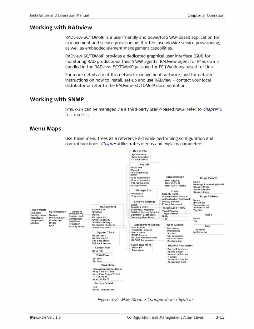
Installation and Operation Manual Chapter 3 Operation
IPmux-24 Ver. 1.5 Configuration and Management Alternatives 3-11
Working with RADview
RADview-SC/TDMoIP is a user-friendly and powerful SNMP-based application for management and service provisioning. It offers pseudowire service provisioning, as well as embedded element management capabilities.
RADview-SC/TDMoIP provides a dedicated graphical user interface (GUI) for monitoring RAD products via their SNMP agents. RADview agent for IPmux-24 is bundled in the RADview-SC/TDMoIP package for PC (Windows-based) or Unix.
For more details about this network management software, and for detailed instructions on how to install, set-up and use RADview – contact your local distributor or refer to the RADview-SC/TDMoIP documentation.
Working with SNMP
IPmux-24 can be managed via a third-party SNMP-based NMS (refer to Chapter 6 for trap list).
Menu Maps
Use these menu trees as a reference aid while performing configuration and control functions. Chapter 4 illustrates menus and explains parameters.
Main MenuSys temConfiguration
Hos t IP
Ma nagement
User A ccess
Control Port
System C lock
InventoryConfigurationMonitoringDiagnosticsUtilities
Management System clock Control port Date/Time ProtectionFactory default
SystemPhysical LayerConnectionBridgeQoS
IP add ress IP mask Default gateway DHCP Read Community Write Community Trap Community Encapsulation
Device infoSNMPv3Host IPManager li stSNMP Engine IDSNMPv3 SettingsManagement accessAlarm trap mask User name
Permission Access 'su' password New password Confirmation
Baud rate
Maser clockMaster sourceFall back clock Fall back source
Date/Time
Protection
Factory Defa ult
Set timeSet date
Ring Administrative StatusKeep Alive Tx T imeKeep Alive Drops To FallPTP VLAN ID Mcast VLAN ID
FullExcept management
System nameSystem locationContact person
Host Tagging Host VLAN IDHost VLAN Priority
Ma nager List
Management Access
Alarm Trap Ma sk
IP addressTrap mask
User Access Telnet/SSH Access Web AccessSNMP Access RADIUS AuthenticationRADIUS Parameters
Alarm ID Trap status
Device Info
Encapsulation
Server IP AddressShared SecretNumber of Retr iesTimeoutAuthentication PortAccounting Port
RADIUS Parameters
UsersTargets & NotifySNMPv1/v3 MappingSNMPv3 Factory DefaultsSummary Target TableSummary User Table
Security NameAuthentication ProtocolAuthentication PasswordPrivacy ProtocolPrivacy Password
Target ParamsTarget AddressNotifyTrap
NameMessage Processing ModelSecurity M odelSecurity N ameSecurity L evel
NameIP AddressParams NameAddress MaskTag List
NameTag
Trap NameNotify Name
SNMPv3 Settings
Users
Targets an d Notify
Target Params
Target Address
Notify
Trap
Figure 3-2. Main Menu > Configuration > System
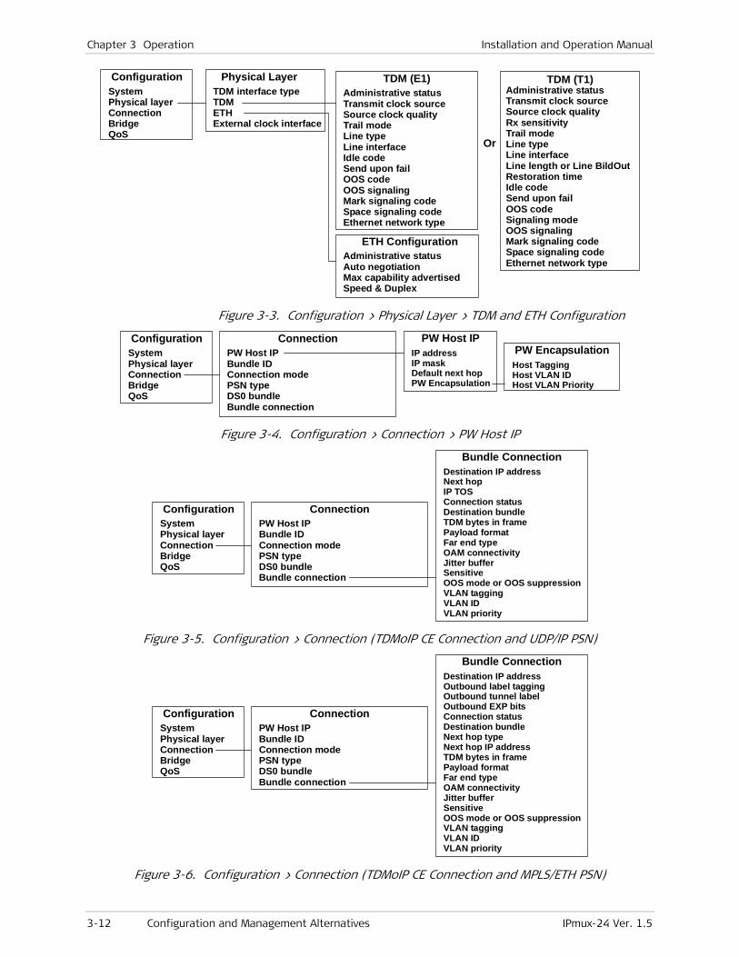
Chapter 3 Operation Installation and Operation Manual
3-12 Configuration and Management Alternatives IPmux-24 Ver. 1.5
Configuration Physical Layer TDM (E1)
Or
TDM (T1)
ETH Configuration
SystemPhysical layerConnectionBridgeQoS
TDM interface typeTDM ETHExternal clock interface
Administrative statusTransmit clock sourceSource clock qualityTrail modeLine typeLine interfaceIdle code Send upon failOOS codeOOS signalingMark signaling codeSpace signaling codeEthernet network type
Administrative
Send upon failOOS codeSignaling modeOOS signalingMark signaling codeSpace signaling codeEthernet network type
statusTransmit clock sourceSource clock qualityRx sensitivityTrail modeLine typeLine interfaceLine length or Line BildOutRestoration timeIdle code
Administrative statusAuto negotiationMax capability advertisedSpeed & Duplex
Figure 3-3. Configuration > Physical Layer > TDM and ETH Configuration
Connection PW Host IPPW EncapsulationPW Host IP
Bundle IDConnection modePSN typeDS0 bundleBundle connection
IP addressIP maskDefault next hop PW Encapsulation
Host TaggingHost VLAN IDHost VLAN Priority
ConfigurationSystemPhysical layerConnectionBridgeQoS
Figure 3-4. Configuration > Connection > PW Host IP
Connection
Bundle Connection
PW Host IPBundle IDConnection modePSN typeDS0 bundleBundle connection
Destination IP addressNext hop IP TOSConnection status Destination bundleTDM bytes in framePayload format Far end type OAM connectivity Jitter buffer Sensitive OOS mode or OOS suppression VLAN tagging VLAN ID VLAN priority
ConfigurationSystemPhysical layerConnectionBridgeQoS
Figure 3-5. Configuration > Connection (TDMoIP CE Connection and UDP/IP PSN)
Connection
Bundle Connection
PW Host IPBundle IDConnection modePSN typeDS0 bundleBundle connection
Destination IP address Outbound label tagging Outbound tunnel label Outbound EXP bits Connection statusDestination bundleNext hop type Next hop IP address TDM bytes in framePayload formatFar end type OAM connectivity Jitter bufferSensitive OOS mode or OOS suppressionVLAN tagging VLAN IDVLAN priority
ConfigurationSystemPhysical layerConnectionBridgeQoS
Figure 3-6. Configuration > Connection (TDMoIP CE Connection and MPLS/ETH PSN)
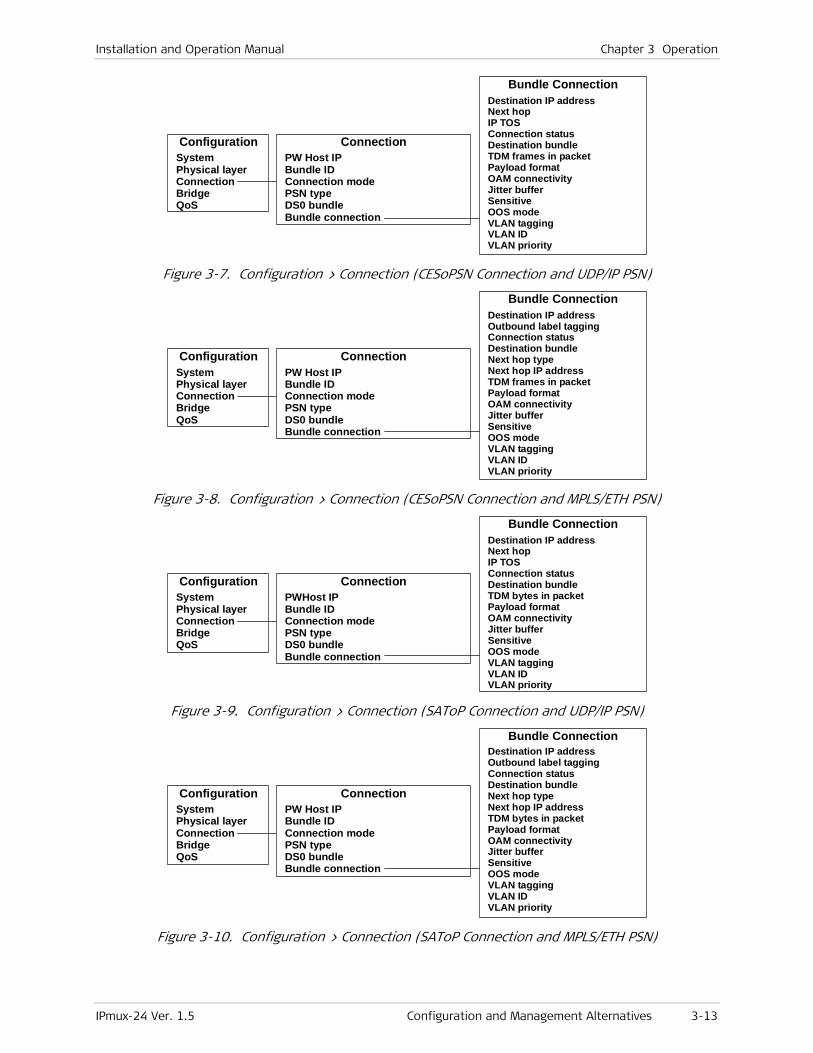
Installation and Operation Manual Chapter 3 Operation
IPmux-24 Ver. 1.5 Configuration and Management Alternatives 3-13
Connection
Bundle Connection
PW Host IPBundle IDConnection modePSN typeDS0 bundleBundle connection
Destination IP address Next hop IP TOS Connection status Destination bundle TDM frames in packet Payload format OAM connectivity Jitter buffer SensitiveOOS modeVLAN tagging
VLAN IDVLAN priority
ConfigurationSystemPhysical layerConnectionBridgeQoS
Figure 3-7. Configuration > Connection (CESoPSN Connection and UDP/IP PSN)
Connection
Bundle Connection
PW Host IPBundle IDConnection modePSN typeDS0 bundleBundle connection
Destination IP address Outbound label tagging Connection status Destination bundle Next hop type Next hop IP address TDM frames in packet Payload format OAM connectivity Jitter bufferSensitive OOS mode VLAN tagging
VLAN IDVLAN priority
ConfigurationSystemPhysical layerConnectionBridgeQoS
Figure 3-8. Configuration > Connection (CESoPSN Connection and MPLS/ETH PSN)
Connection
Bundle Connection
PWHost IPBundle IDConnection modePSN typeDS0 bundleBundle connection
Destination IP address Next hop IP TOS Connection status Destination bundle TDM bytes in packet Payload format OAM connectivityJitter bufferSensitiveOOS modeVLAN tagging VLAN ID VLAN priority
ConfigurationSystemPhysical layerConnectionBridgeQoS
Figure 3-9. Configuration > Connection (SAToP Connection and UDP/IP PSN)
Connection
Bundle Connection
PW Host IPBundle IDConnection modePSN typeDS0 bundleBundle connection
Destination IP address Outbound label tagging Connection status Destination bundle Next hop type Next hop IP addressTDM bytes in packetPayload format OAM connectivity Jitter buffer Sensitive OOS mode VLAN taggingVLAN ID VLAN priority
ConfigurationSystemPhysical layerConnectionBridgeQoS
Figure 3-10. Configuration > Connection (SAToP Connection and MPLS/ETH PSN)
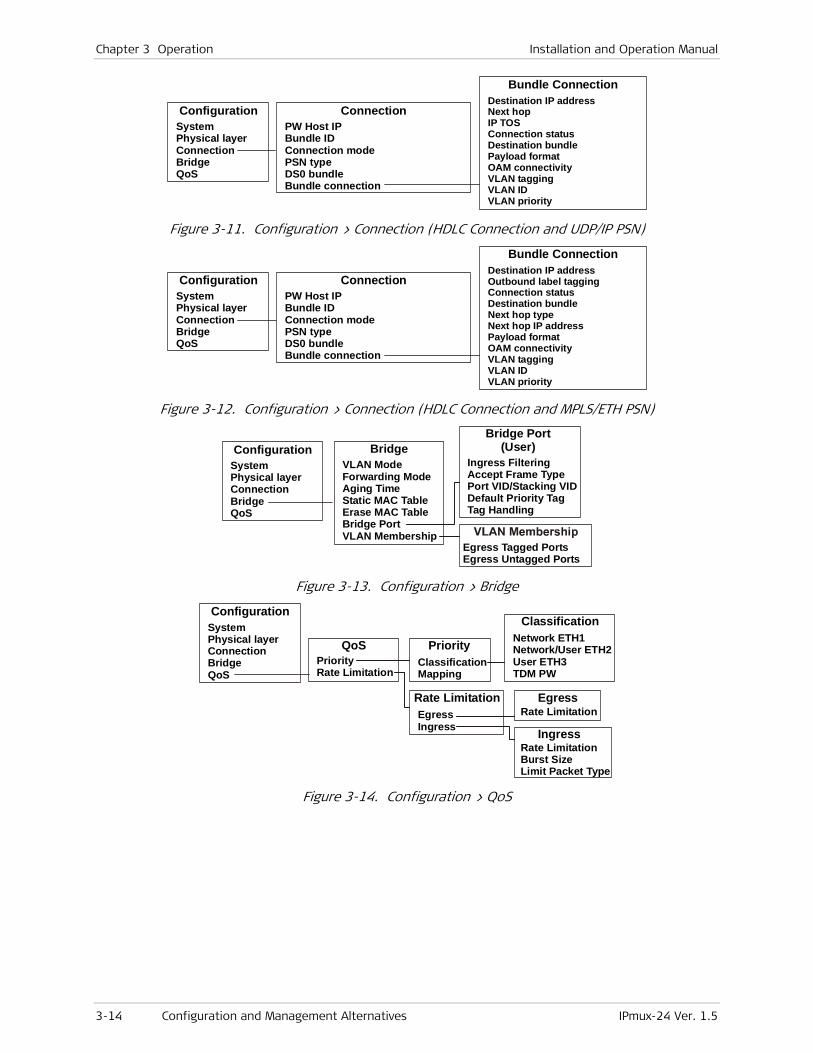
Chapter 3 Operation Installation and Operation Manual
3-14 Configuration and Management Alternatives IPmux-24 Ver. 1.5
Connection
Bundle Connection
PW Host IPBundle IDConnection modePSN typeDS0 bundleBundle connection
Destination IP address Next hop IP TOS Connection status Destination bundle Payload formatOAM connectivity VLAN tagging VLAN ID VLAN priority
ConfigurationSystemPhysical layerConnectionBridgeQoS
Figure 3-11. Configuration > Connection (HDLC Connection and UDP/IP PSN)
Connection
Bundle Connection
PW Host IPBundle IDConnection modePSN typeDS0 bundleBundle connection
Destination IP addressOutbound label tagging Connection status Destination bundle Next hop type Next hop IP address Payload format OAM connectivity VLAN tagging VLAN ID VLAN priority
ConfigurationSystemPhysical layerConnectionBridgeQoS
Figure 3-12. Configuration > Connection (HDLC Connection and MPLS/ETH PSN)
ConfigurationSystemPhysical layerConnectionBridgeQoS
Egress Tagged PortsEgress Untagged Ports
Ingress FilteringAccept Frame TypePort VID
Tag Handling
/Stacking VIDDefault Priority Tag
VLAN ModeForwarding ModeAging TimeStatic MAC TableErase MAC TableBridge PortVLAN Membership
BridgeBridge Port
(User)
Figure 3-13. Configuration > Bridge
ConfigurationSystemPhysical layerConnectionBridgeQoS
PriorityRate Limitation
ClassificationMapping
Network ETH1Network/User ETH2User ETH3TDM PW
EgressIngress
Rate Limitation
Rate LimitationBurst SizeLimit Packet Type
QoS Priority
Classification
Rate Limitation Egress
Ingress
Figure 3-14. Configuration > QoS

Installation and Operation Manual Chapter 3 Operation
IPmux-24 Ver. 1.5 Turning IPmux-24 Off 3-15
Monitoring Statistics
StatusPhysical Ports
SFP
Event Log
Managers
StatisticsStatusEvent logManagers
TDM physical layerConnectionBridge
Diagnostics loopback Physical ports ConnectionSystem ClockProtection
ETH physical layer SFP Link status
Read log fileClear log file
Connected Managers
Figure 3-15. Monitoring
DiagnosticsPing
Trace Route
Loopback
Self Test Results
PingTrace routeLoopbackSelf test results
InterfaceDestination IP addressVLAN tagging
Number of frames to sendPing Send
VLAN IDVLAN priority
Destination IP addressVLAN tagging VLAN IDVLAN priorityTrace route send
Loopback stateInband loop detection (T1 only)
Framer testBridge test
Figure 3-16. Diagnostics
Utilities File Utilities Download/Upload Using FTPFile UtilitiesReset
Download/upload using FTP File name Command Server IP Retry timeoutTotal timeout View transfer status
Figure 3-17. Utilities
3.5 Turning IPmux-24 Off
To power off the unit:
• Remove the power cord from the power source.

Chapter 3 Operation Installation and Operation Manual
3-16 Turning IPmux-24 Off IPmux-24 Ver. 1.5
IPmux-24 Ver. 1.5 Configuring IPmux-24 for Management 4-1
Chapter 4
Configuration This chapter illustrates the configuration IPmux-24 screens and explains their parameters.
Menu trees of the IPmux-24 management software are shown in Chapter 3.
4.1 Configuring IPmux-24 for Management
Usually, initial configuration of the management parameters is performed via ASCII terminal. Once the IPmux-24 host IP parameters are set, it is possible to access it via Telnet, Web terminal or RADview for operation configuration. Perform the following steps in order to configure IPmux-24 for management:
To configure IPmux-24 for management:
1. Connect an ASCII terminal to the RS-232 control port of IPmux-24.
2. Log in as Superuser (su).
3. Enable or disable the IPmux-24 DHCP client.
4. Assign an IP address to IPmux-24.
5. Assign a subnet mask and a default gateway.
6. Configure the SNMP communities.
7. Set a manager IP address.
Make sure that you save your settings at each configuration screen.
Configuring IP Host Parameters
IPmux-24 can be managed by a network management station, which is located on the LAN connected to the one of the unit’s Ethernet ports. In order to establish a proper connection, it is necessary to configure the following: host IP address, subnet mask, default gateway, its trap, read and write communities. In addition, you can enable or disable DHCP client of the device.
Note

Chapter 4 Configuration Installation and Operation Manual
4-2 Configuring IPmux-24 for Management IPmux-24 Ver. 1.5
Configuring DHCP Client
To facilitate integration of a new device into a DHCP IP network, if no IP address has been manually configured, IPmux-24 automatically requests one from the DHCP server upon booting. IPmux-24 is shipped with the DHCP client set to Enable.
Managing IP Parameters of the IPmux-24 Host
IPmux-24 allows entering IP parameters manually or using parameters acquired from the DHCP server.
To define the IP parameters manually:
1. Disable DHCP client.
IPmux-24 releases the current IP address by sending the release message to the DHCP server, sets all host IP parameters to 0.0.0.0 and reboots itself automatically.
2. From the Host IP menu (Configuration > System > Management > Host IP), perform the following:
Select IP Address to define the host IP address
Select IP Mask to define the host IP mask.
Select Default Gateway to set the default gateway IP address.
The default gateway must be in the same subnet as the host.
Configuration>System>Management>Host IP 1. IP address ... (–) 2. IP mask ... (0.0.0.0) 3. Default gateway ... (–) 4. DHCP (Enable) 5. DHCP Status > 6. Read Community ... (public) 7. Write Community ... (private) 8. Trap Community ... (SNMP_trap) 9. Encapsulation > > Please select item <1 to 9> ESC-prev.menu; !-main menu; &-exit 1 Mngr/s
Figure 4-1. Host IP Menu
To acquire a new IP address from the DHCP server:
1. From the Host IP menu, set all host IP parameters (host IP, IP mask and default gateway) to 0.0.0.0 or reset the IPmux-24 configuration to the default settings, including the management parameters.
IPmux-24 reboots automatically.
Note

Installation and Operation Manual Chapter 4 Configuration
IPmux-24 Ver. 1.5 Configuring IPmux-24 for Management 4-3
After returning on line, IPmux-24 starts broadcasting requests for an IP address. When the DHCP server is found, IPmux-24 receives from it all necessary host IP parameters.
2. From the Host IP menu, select DHCP Status to view the current status of the IPmux-24 DHCP client:
Server ID – IP address of the DHCP server
Lease expiration time – Time when the IP address lease expires
Current status – Current status of the DHCP client (Locating available server, Waiting for confirmation of lease, etc)
When the IP address lease is going to expire, DHCP client automatically requests lease extension.
Defining Read, Write and Trap Communities
You have to assign names for the read, write and trap communities.
To define read, write and trap communities:
• From the Host IP menu (Figure 4-1), configure the following:
Select Read Community to enter the name of a community with read-only authorization (up to 10 alphanumeric characters, case-sensitive).
Select Write Community to enter the name of a community with write authorization (up to 10 alphanumeric characters, case-sensitive).
Select Trap Community to enter the name of a community to which IPmux-24 will send traps (up to 10 alphanumeric characters, case-sensitive).
Configuring the Host Encapsulation
IPmux-24 management software allows you to create a dedicated management VLAN in order to separate management traffic from the user data.
To configure the host encapsulation:
1. From the Host menu (Figure 4-1), select Encapsulation.
The Encapsulation menu is displayed (see Figure 4-2).
2. From the Encapsulation menu, do the following:
Select Host tagging, and choose Tagged or Untagged to consider or ignore the VLAN tagging of the management traffic coming from the management station.
If the host tagging is enabled, select Host VLAN ID to enter the ID of the host VLAN (1–4094).
If the host tagging is enabled, select Host VLAN priority to specify priority of the host VLAN (0–7).
Note
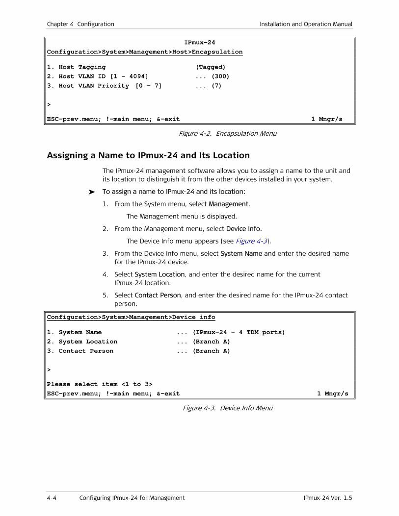
Chapter 4 Configuration Installation and Operation Manual
4-4 Configuring IPmux-24 for Management IPmux-24 Ver. 1.5
IPmux-24 Configuration>System>Management>Host>Encapsulation
1. Host Tagging (Tagged) 2. Host VLAN ID [1 - 4094] ... (300) 3. Host VLAN Priority [0 - 7] ... (7) > ESC-prev.menu; !-main menu; &-exit 1 Mngr/s
Figure 4-2. Encapsulation Menu
Assigning a Name to IPmux-24 and Its Location
The IPmux-24 management software allows you to assign a name to the unit and its location to distinguish it from the other devices installed in your system.
To assign a name to IPmux-24 and its location:
1. From the System menu, select Management.
The Management menu is displayed.
2. From the Management menu, select Device Info.
The Device Info menu appears (see Figure 4-3).
3. From the Device Info menu, select System Name and enter the desired name for the IPmux-24 device.
4. Select System Location, and enter the desired name for the current IPmux-24 location.
5. Select Contact Person, and enter the desired name for the IPmux-24 contact person.
Configuration>System>Management>Device info
1. System Name ... (IPmux-24 - 4 TDM ports) 2. System Location ... (Branch A) 3. Contact Person ... (Branch A) > Please select item <1 to 3> ESC-prev.menu; !-main menu; &-exit 1 Mngr/s
Figure 4-3. Device Info Menu
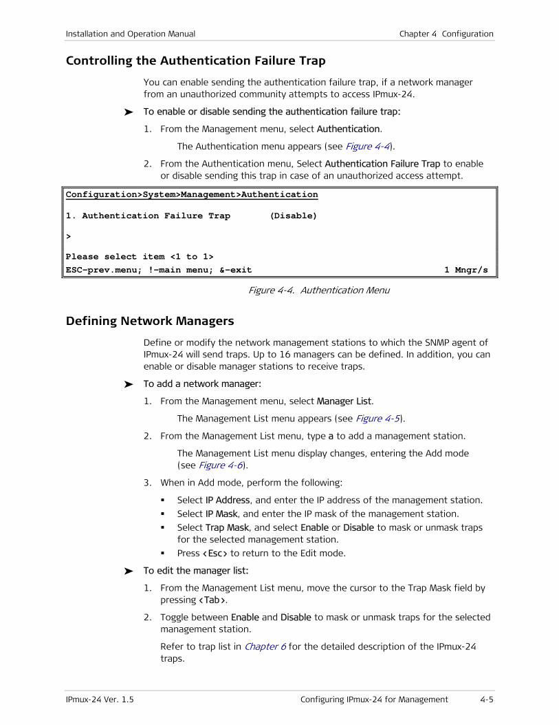
Installation and Operation Manual Chapter 4 Configuration
IPmux-24 Ver. 1.5 Configuring IPmux-24 for Management 4-5
Controlling the Authentication Failure Trap
You can enable sending the authentication failure trap, if a network manager from an unauthorized community attempts to access IPmux-24.
To enable or disable sending the authentication failure trap:
1. From the Management menu, select Authentication.
The Authentication menu appears (see Figure 4-4).
2. From the Authentication menu, Select Authentication Failure Trap to enable or disable sending this trap in case of an unauthorized access attempt.
Configuration>System>Management>Authentication
1. Authentication Failure Trap (Disable) > Please select item <1 to 1> ESC-prev.menu; !-main menu; &-exit 1 Mngr/s
Figure 4-4. Authentication Menu
Defining Network Managers
Define or modify the network management stations to which the SNMP agent of IPmux-24 will send traps. Up to 16 managers can be defined. In addition, you can enable or disable manager stations to receive traps.
To add a network manager:
1. From the Management menu, select Manager List.
The Management List menu appears (see Figure 4-5).
2. From the Management List menu, type a to add a management station.
The Management List menu display changes, entering the Add mode (see Figure 4-6).
3. When in Add mode, perform the following:
Select IP Address, and enter the IP address of the management station.
Select IP Mask, and enter the IP mask of the management station.
Select Trap Mask, and select Enable or Disable to mask or unmask traps for the selected management station.
Press <Esc> to return to the Edit mode.
To edit the manager list:
1. From the Management List menu, move the cursor to the Trap Mask field by pressing <Tab>.
2. Toggle between Enable and Disable to mask or unmask traps for the selected management station.
Refer to trap list in Chapter 6 for the detailed description of the IPmux-24 traps.

Chapter 4 Configuration Installation and Operation Manual
4-6 Configuring IPmux-24 for Management IPmux-24 Ver. 1.5
To remove a network manager:
1. From the Manager List, select a network manager that you intend to remove.
2. Type r to remove the selected network manager from the list.
To clear the manager list:
• From the Manager List, type c to delete all network managers.
Configuration>System>Management>Manager List
Manager ID IP Address IP mask Trap mask
1 172.18.159.35 255.255.255.0 Disable
1. Change cell ... (172.18.159.35) A – add R – remove C – clear table ESC-prev.menu; !-main menu; &-exit; ?-help
Figure 4-5. Manager List Menu
Configuration>System> Management > Manager List Manager ID (1) 1. IP Address ... (0.0.0.0) 2. IP mask ... (0.0.0.0) 3. Trap Mask ... (Disable) > ESC-prev.menu; !-main menu; &-exit 1 Mngr/s
Figure 4-6. Manager List Menu, Add Mode
Configuring SNMPv3
IPmux-24 supports SNMP version 3 entity, providing secure access to the device by authenticating and encrypting packets transmitted over the network.
Follow these steps to configure the SNMPv3 entity:
1. Define SNMP engine ID
2. Enable SNMPv3.
3. Add a new user or use a default user account.
4. Add a new notification entry.
5. Assign traps to notification entries.
6. Configure target (NMS) parameters.
7. Specify target address, define its parameter set and assign notification tags.
8. Map SNMPv3 setting to SNMPv1 settings. This is necessary for coexistence of different SNMP versions. For example, when managing an SNMPv3 agent via an SNMPv1 NMS.

Installation and Operation Manual Chapter 4 Configuration
IPmux-24 Ver. 1.5 Configuring IPmux-24 for Management 4-7
Configuring the SNMP Engine ID
Engine ID is an alphanumeric string used for identification of the IPmux-24 agent in the SNMPv3 environment. The engine ID must be unique to allow the user to query the SNMP engine. It must be defined prior to enabling SNMPv3 functionality. The length of the string is up to 27 characters.
To define the SNMP engine ID:
• From the SNMP Engine ID menu (Configuration > System > Management > SNMP Engine ID), select Rest Bytes and define the value of the engine ID section reserved for user SNMP engine identification.
The value is automatically translated in hexadecimal format and displayed in the read-only Engine ID field.
Configuration>System> Management>SNMP Engine ID
Engine ID ... (800000a40400000000) Engine ID Config Type > (Text)
1. Rest Bytes ... () > ESC-prev.menu; !-main menu; &-exit 1 M/ 1 C
Figure 4-7. SNMP Engine ID Menu
Enabling SNMPv3
To enable SNMPv3:
1. From the Management menu (Configuration > System > Management), select SNMPv3 to enable the SNMPv3 entity.
The SNMPv3 Settings line is added to the Management menu.
2. From the Management menu, select SNMPv3 Settings.
The SNMPv3 Settings menu is displayed.
The SNMPv3 Settings menu includes the following information:
Engine Boots (The number of times that the SNMP engine has reinitialized since its identification was last configured.)
Engine Time (The number of seconds since the last SNMP engine boot)
SNMP Message Size (The maximum length of an SNMP message (in octets) that the SNMP engine can send or receive and process.)

Chapter 4 Configuration Installation and Operation Manual
4-8 Configuring IPmux-24 for Management IPmux-24 Ver. 1.5
IPmux-24 Configuration>System>Management>SNMPv3 Settings Engine Boots (2) Engine Time (276) SNMP Message Size ... (1500) 1. Users > 2. Targets & Notify > 3. SNMPv1/v3 Mapping > 4. SNMPv3 Factory Defaults 5. Summary Target Table [] 6. Summary User Table [] > ESC-prev.menu; !-main menu; &-exit 1 Mngr/s
Figure 4-8. SNMPv3 Settings Menu
Adding SNMPv3 Users
IPmux-24 supports up to ten SNMPv3 managers with different authorization and privacy attributes.
Access control policy is defined via the vacmSecurityToGroupTable and vacmAccessTable tables, which can be accessed via an SNMP browser only.
To add an SNMPv3 user:
1. From the Users menu (Configuration > System > Management > SNMPv3 Settings > Users), perform the following:
Select Security Name and enter security name for a new user (up to 32 alphanumeric characters).
Select Authentication Protocol and define the authentication protocol to be used for authenticating the user:
usmNoAuthProtocol (No authentication is performed)
usmHMACMD5AuthProtocol (MD5 protocol)
usmHMACSHAAuthProtocol (SHA protocol)
Select Privacy Protocol and define the type of privacy protocol to be used for encryption:
usmNoPrivProtocol (Privacy protocol is not used)
usmDESPrivProtocol (DES protocol)
Select Authentication Password (eight characters) and define the authentication password of the user. This is not available if authentication has been disabled.
Select Privacy Password (eight characters) and define the private key used for encryption. This is not available if privacy has been disabled.
Note
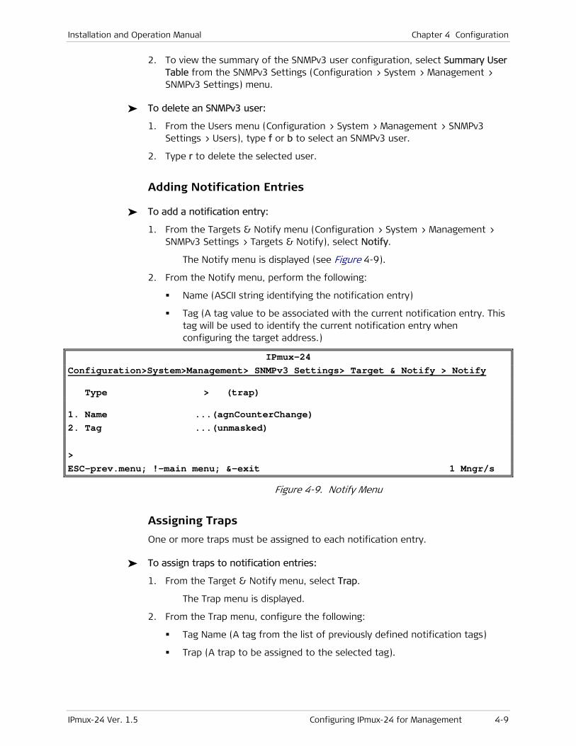
Installation and Operation Manual Chapter 4 Configuration
IPmux-24 Ver. 1.5 Configuring IPmux-24 for Management 4-9
2. To view the summary of the SNMPv3 user configuration, select Summary User Table from the SNMPv3 Settings (Configuration > System > Management > SNMPv3 Settings) menu.
To delete an SNMPv3 user:
1. From the Users menu (Configuration > System > Management > SNMPv3 Settings > Users), type f or b to select an SNMPv3 user.
2. Type r to delete the selected user.
Adding Notification Entries
To add a notification entry:
1. From the Targets & Notify menu (Configuration > System > Management > SNMPv3 Settings > Targets & Notify), select Notify.
The Notify menu is displayed (see Figure 4-9).
2. From the Notify menu, perform the following:
Name (ASCII string identifying the notification entry)
Tag (A tag value to be associated with the current notification entry. This tag will be used to identify the current notification entry when configuring the target address.)
IPmux-24 Configuration>System>Management> SNMPv3 Settings> Target & Notify > Notify
Type > (trap)
1. Name ...(agnCounterChange) 2. Tag ...(unmasked) > ESC-prev.menu; !-main menu; &-exit 1 Mngr/s
Figure 4-9. Notify Menu
Assigning Traps
One or more traps must be assigned to each notification entry.
To assign traps to notification entries:
1. From the Target & Notify menu, select Trap.
The Trap menu is displayed.
2. From the Trap menu, configure the following:
Tag Name (A tag from the list of previously defined notification tags)
Trap (A trap to be assigned to the selected tag).
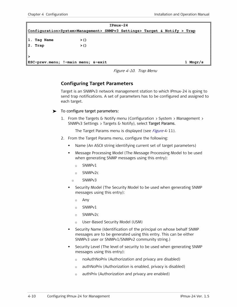
Chapter 4 Configuration Installation and Operation Manual
4-10 Configuring IPmux-24 for Management IPmux-24 Ver. 1.5
IPmux-24 Configuration>System>Management> SNMPv3 Settings> Target & Notify > Trap
1. Tag Name >() 2. Trap >() > ESC-prev.menu; !-main menu; &-exit 1 Mngr/s
Figure 4-10. Trap Menu
Configuring Target Parameters
Target is an SNMPv3 network management station to which IPmux-24 is going to send trap notifications. A set of parameters has to be configured and assigned to each target.
To configure target parameters:
1. From the Targets & Notify menu (Configuration > System > Management > SNMPv3 Settings > Targets & Notify), select Target Params.
The Target Params menu is displayed (see Figure 4-11).
2. From the Target Params menu, configure the following:
Name (An ASCII string identifying current set of target parameters)
Message Processing Model (The Message Processing Model to be used when generating SNMP messages using this entry):
SNMPv1
SNMPv2c
SNMPv3
Security Model (The Security Model to be used when generating SNMP messages using this entry):
Any
SNMPv1
SNMPv2c
User-Based Security Model (USM)
Security Name (Identification of the principal on whose behalf SNMP messages are to be generated using this entry. This can be either SNMPv3 user or SNMPv1/SNMPv2 community string.)
Security Level (The level of security to be used when generating SNMP messages using this entry):
noAuthNoPriv (Authorization and privacy are disabled)
authNoPriv (Authorization is enabled, privacy is disabled)
authPriv (Authorization and privacy are enabled)
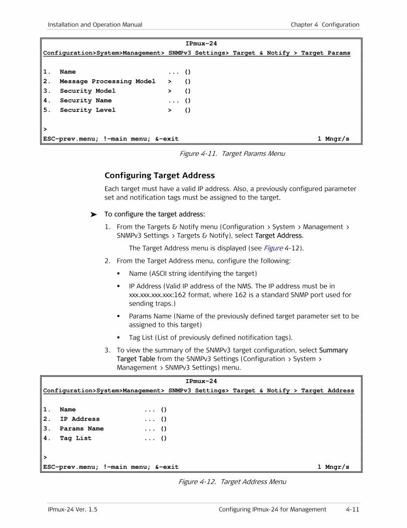
Installation and Operation Manual Chapter 4 Configuration
IPmux-24 Ver. 1.5 Configuring IPmux-24 for Management 4-11
IPmux-24 Configuration>System>Management> SNMPv3 Settings> Target & Notify > Target Params
1. Name ... () 2. Message Processing Model > () 3. Security Model > () 4. Security Name ... () 5. Security Level > () > ESC-prev.menu; !-main menu; &-exit 1 Mngr/s
Figure 4-11. Target Params Menu
Configuring Target Address
Each target must have a valid IP address. Also, a previously configured parameter set and notification tags must be assigned to the target.
To configure the target address:
1. From the Targets & Notify menu (Configuration > System > Management > SNMPv3 Settings > Targets & Notify), select Target Address.
The Target Address menu is displayed (see Figure 4-12).
2. From the Target Address menu, configure the following:
Name (ASCII string identifying the target)
IP Address (Valid IP address of the NMS. The IP address must be in xxx.xxx.xxx.xxx:162 format, where 162 is a standard SNMP port used for sending traps.)
Params Name (Name of the previously defined target parameter set to be assigned to this target)
Tag List (List of previously defined notification tags).
3. To view the summary of the SNMPv3 target configuration, select Summary Target Table from the SNMPv3 Settings (Configuration > System > Management > SNMPv3 Settings) menu.
IPmux-24 Configuration>System>Management> SNMPv3 Settings> Target & Notify > Target Address
1. Name ... () 2. IP Address ... () 3. Params Name ... () 4. Tag List ... () > ESC-prev.menu; !-main menu; &-exit 1 Mngr/s
Figure 4-12. Target Address Menu
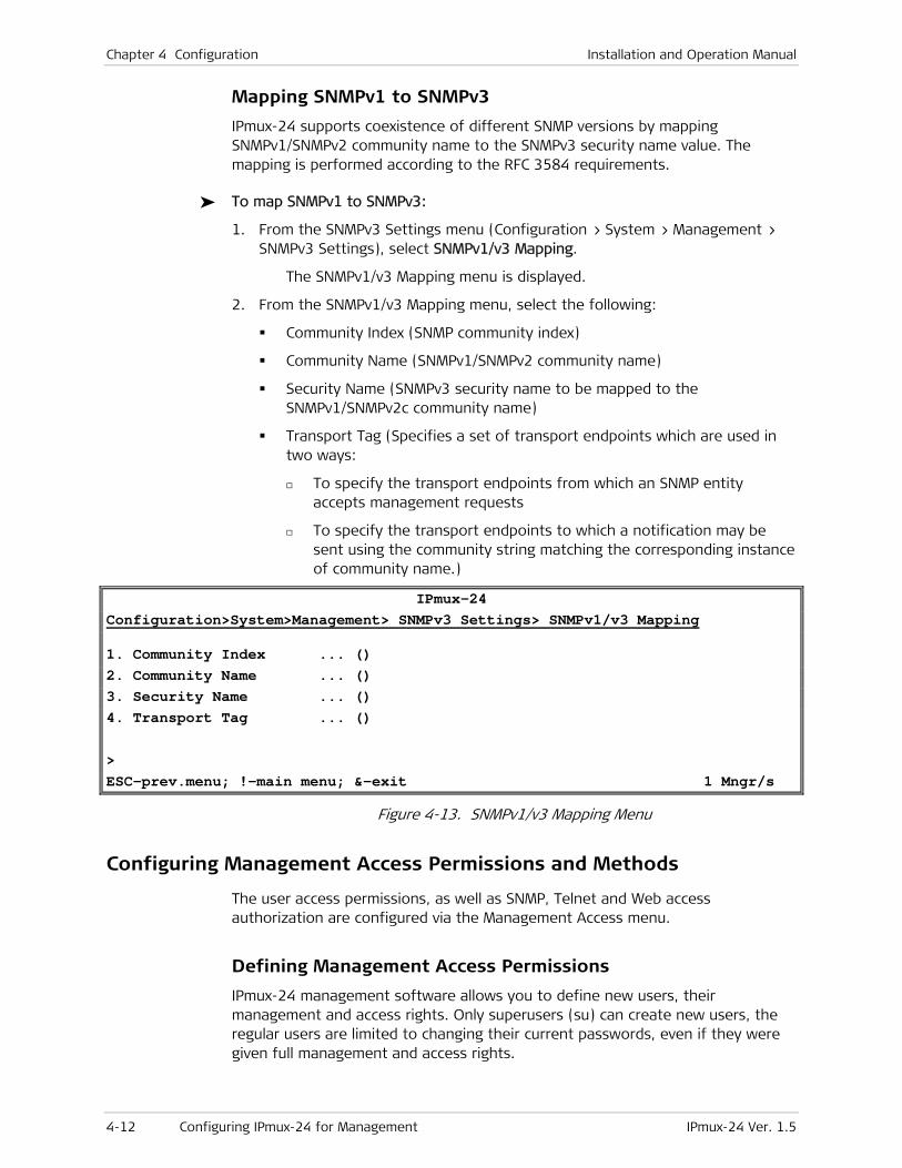
Chapter 4 Configuration Installation and Operation Manual
4-12 Configuring IPmux-24 for Management IPmux-24 Ver. 1.5
Mapping SNMPv1 to SNMPv3
IPmux-24 supports coexistence of different SNMP versions by mapping SNMPv1/SNMPv2 community name to the SNMPv3 security name value. The mapping is performed according to the RFC 3584 requirements.
To map SNMPv1 to SNMPv3:
1. From the SNMPv3 Settings menu (Configuration > System > Management > SNMPv3 Settings), select SNMPv1/v3 Mapping.
The SNMPv1/v3 Mapping menu is displayed.
2. From the SNMPv1/v3 Mapping menu, select the following:
Community Index (SNMP community index)
Community Name (SNMPv1/SNMPv2 community name)
Security Name (SNMPv3 security name to be mapped to the SNMPv1/SNMPv2c community name)
Transport Tag (Specifies a set of transport endpoints which are used in two ways:
To specify the transport endpoints from which an SNMP entity accepts management requests
To specify the transport endpoints to which a notification may be sent using the community string matching the corresponding instance of community name.)
IPmux-24 Configuration>System>Management> SNMPv3 Settings> SNMPv1/v3 Mapping
1. Community Index ... () 2. Community Name ... () 3. Security Name ... () 4. Transport Tag ... () > ESC-prev.menu; !-main menu; &-exit 1 Mngr/s
Figure 4-13. SNMPv1/v3 Mapping Menu
Configuring Management Access Permissions and Methods
The user access permissions, as well as SNMP, Telnet and Web access authorization are configured via the Management Access menu.
Defining Management Access Permissions
IPmux-24 management software allows you to define new users, their management and access rights. Only superusers (su) can create new users, the regular users are limited to changing their current passwords, even if they were given full management and access rights.

Installation and Operation Manual Chapter 4 Configuration
IPmux-24 Ver. 1.5 Configuring IPmux-24 for Management 4-13
To add a new user:
1. Make sure that you logged in as su.
2. From the Management Access menu, select User access.
The User Access menu is displayed (see Figure 4-14).
3. From the User Access menu, do the following:
Select User name, and enter a name for a new user.
Select Permission, and specify the user’s access rights (full control or read-only).
Select Access, and specify the user’s access methods (ASCII terminal, Telnet, Web browser, Telnet and Web browser, or all of them).
When changing Permission and Access for an existing user, make sure to fill out the ‘SU’ Password, New Password and Confirm fields (you can enter the current user password for the New Password and Confirm).
Select 'su' Password, and enter your current superuser password.
Select New Password, and assign a password to a new user name.
Select Confirm and re-enter the new user password to confirm it.
Save new settings by typing S, when asked.
To delete an existing user:
• From the User Access menu, do the following:
Type F to display a user that you intend to delete.
Select 'su' password, and enter your current superuser password.
Type D to delete the current user.
Configuration>System>Management>Management access>User access
1. User name ... (su) 2. Permission > (Full Control) 3. Access > (All) 4. 'su' password ... () 5. New password ... () 6. Confirmation ... () > Please select item <1 to 6> ESC-prev.menu; !-main menu; &-exit 1 Mngr/s
Figure 4-14. User Access Menu
Note

Chapter 4 Configuration Installation and Operation Manual
4-14 Configuring IPmux-24 for Management IPmux-24 Ver. 1.5
Controlling Management Access
You can enable or disable access to the IPmux-24 management system via an SNMP, Telnet or Web-based application. By disabling SNMP, Telnet or Web, you prevent unauthorized access to the system when security of the IPmux-24 IP address has been compromised. When SNMP, Telnet and Web access is disabled, IPmux-24 can be managed via an ASCII terminal only. In addition, you can limit access to the device to only the stations defined in the manager list. Table 4-1 details management access implementation, depending whether the network managers are defined or not.
To define the management access method:
1. From the Management menu, select Management Access.
The Management Access menu appears.
2. From the Management Access menu, select Telnet/SSH Access to configure Telnet access, select SNMP Access to configure SNMP access, or select Web Access to configure Web access.
3. Define access mode for each management method:
Enable (Telnet, SNMP or Web access is enabled)
Disable (Telnet, SNMP or Web access is disabled)
Managers Only (Access is allowed only for the stations appearing in the manager list)
Enable Secure (Secure access (SSH-enabled for Secure Shell or SSL-enabled for Web) is enabled)
Manager Only Secure (Secure access (SSH-enabled for Secure Shell or SSL-enabled for Web) is allowed only for the stations appearing in the manager list).
Table 4-1. Management Access Implementation
Access Method Mode Who is Allowed to Access IPmux-24
Network Manager(s)
Defined
Network Manager(s) not
Defined
SNMP Access
Enable Anybody Anybody
Disable Nobody Nobody
Managers Only Only defined network
managers
Nobody
Telnet Access
Enable/Enable Secure Anybody Anybody
Disable Nobody Nobody
Managers Only/
Managers Only Secure
Anybody Only defined network
managers
Web Access
Enable/Enable Secure Anybody Anybody
Disable Nobody Nobody
Managers Only/
Managers Only Secure
Only defined network
managers
Anybody

Installation and Operation Manual Chapter 4 Configuration
IPmux-24 Ver. 1.5 Configuring IPmux-24 for Management 4-15
IPmux-24 Configuration>System>Management>Management Access
1. User Access > 2. TELNET/SSH access > (Enable) 3. SNMP access > (Disable) 4. WEB access > (Enable) 5. RADIUS Authentication > (Enable Remote) 6. RADIUS Parameters > > ESC-prev.menu; !-main menu; &-exit 1 Mngr/s
Figure 4-15. Management Access Menu
Configuring RADIUS Client
The RADIUS (Remote Authentication Dial-In User Service) is a client/server security protocol. Security information is stored in a central location, known as the RADIUS server. RADIUS clients, such as IPmux-24, communicate with the RADIUS server to authenticate users.
When enabled, IPmux-24 RADIUS client operates in the following modes:
• Remote – IPmux-24 uses authentication database stored at the RADIUS server
• Remote/Local – IPmux-24 uses both RADIUS and local authentication databases.
To configure RADIUS operation mode:
• From the Manager Access menu, select RADIUS Authentication and select one of the authentication modes:
Disable – RADIUS authentication is disabled
Enable Remote – IPmux-24 uses authentication database stored at the RADIUS server to check if the entered user name and password match the data server records. User authentication fails if one the following occurs:
No user name record is found
Password does not match user name
Connection to the RADIUS server is lost.
Enable Remote Local – IPmux-24 uses authentication database stored at the RADIUS server to check if the entered user name and password match the data server records. If no user name record is found or a password does not match user name, connection to the RADIUS server is lost, IPmux-24 uses its internal authentication database.
To configure RADIUS client:
• From the Manager Access menu, select RADIUS Parameters and configure the following:
Server IP Address (IP address of the RADIUS server)

Chapter 4 Configuration Installation and Operation Manual
4-16 Configuring IPmux-24 for Management IPmux-24 Ver. 1.5
Shared Secret (The shared secret is a password used by RADIUS to authenticate the client. IPmux-24 encrypts the user-password, if present; using the secret it shares with the RADIUS server.): Any alphanumeric string up to 16 characters
Number of retries (The number of retries to be made when sending request to the RADIUS server): 1–5
Timeout (The maximum time IPmux-24 waits for a single request response from the RADIUS server (in seconds). After this time the request is retransmitted.): 1–60
Authentication Port (The UDP port number to be used for the RADIUS authentication application. Make sure to define the same value in the RADIUS server.): any valid UDP port number
Accounting Port (The UDP port number to be used for the RADIUS accounting. Make sure to define the same value in the RADIUS server.): any valid UDP port number.
Configuring Control Port Parameters
Configuration parameters of the IPmux-24 control port, except for the baud rate are set at the factory and cannot be changed by the user (see Figure 4-16). These parameters have the following values:
• Data bits – 8
• Parity – None
• Stop bits – 1
• Flow control – None.
To select the baud rate:
1. From the System menu, select Control port.
The Control Port menu is displayed (see Figure 4-16).
2. From the Control Port menu, select Baud rate, and configure baud rate of the IPmux-24 terminal control port to the desired value (9600, 19200, 38400, 57600 or 11520 bps).
Configuration>System>Control port
Data bits (8) Parity > (None) Stop bits (1) Flow control > (None) 1. Baud rate (bps) > (115200) > ESC-prev.menu; !-main menu; &-exit 1 Mngr/s
Figure 4-16. Control Port Menu
Installation and Operation Manual Chapter 4 Configuration
IPmux-24 Ver. 1.5 Configuring IPmux-24 for Operation 4-17
4.2 Configuring IPmux-24 for Operation
The recommended operation configuration procedure for IPmux-24 includes the following stages:
1. Defining system clock.
2. Configuring IPmux-24 interfaces (Ethernet, E1, T1) at the physical level.
3. Creating bundles by allocating timeslots to them.
4. Connecting bundles by directing them to remote device.
Setting Device-Level Parameters
At the device level, you have to configure the system clock to provide a single clock source for E1/T1 links of the device and a ring application to protect the Ethernet transmission path.
Configuring the System Clock
IPmux-24 system timing mechanism ensures a single clock source for all TDM links by providing the master and fallback clocks. If the system clock is locked to one of the IPmux-24 TDM links, it is necessary to define clock source (adaptive or loopback). See Configuring the E1 TDM Interface for details.
To configure the system clock:
1. From the System menu, select System clock.
The System clock menu appears (See Figure 4-17).
2. From the System clock menu, configure the following:
Master clock (Master clock type):
Adaptive (Clock is regenerated from an E1 bundle)
Rx Clock (E1/T1 recovered Rx clock is used as the Tx clock)
Master source (Source of the master clock, when the master clock type is adaptive or Rx):
Channel 1–4 (Master clock is provided via one of the TDM links. E1/T1 links can be locked to adaptive or loopback clock.)
Fallback clock (Fallback clock type):
Adaptive (Clock is regenerated from an E1 bundle)
Rx Clock (E1/T1 recovered Rx clock is used as the Tx clock)
Fallback source (Source of the master clock, when the fallback clock type is adaptive or Rx):
Channel 1–4 (Fallback clock is provided via one of the TDM links. E1/T1 links can be locked to adaptive or loopback clock.)

Chapter 4 Configuration Installation and Operation Manual
4-18 Configuring IPmux-24 for Operation IPmux-24 Ver. 1.5
If the configured fallback clock source fails, the internal timing is used as the fallback clock source instead.
Configuration>System>System clock
1. Master clock > (Rx Clock) 2. Master source > (–) 3. Fall back clock > (Adaptive) 4. Fall back source > (Channel) > Please select item <1 to 2> S - save ESC-prev.menu; !-main menu; &-exit 1 Mngr/s
Figure 4-17. System Clock Menu
Selecting the TDM Interface Type
Before configuring the IPmux-24 TDM interfaces, it is necessary to select their type (E1 or T1).
To select the TDM interface type:
1. From the Configuration menu, select Physical layer.
The Physical Layer menu appears (see Figure 4-18).
3. From the Physical Layer menu, select TDM interface type, and choose the type of the IPmux-24 TDM links (E1 or T1).
Configuration>Physical layer
1. TDM interface type > (E1) 2. TDM > 3. ETH > 4. External clock interface (Balanced) > Please select item <1 to 4> ESC-prev.menu; !-main menu; &-exit 1 Mngr/s
Figure 4-18. Physical Layer Menu
Configuring the Ring Protection
Ring redundancy, implemented by means of the RAD-proprietary protocol, provides protection for the Ethernet transmission path, and is especially suited for MAN and dark fiber applications.
A single ring may include up to 16 IPmux-24 devices and up to 16 VLAN (including an additional VLAN for management traffic). Two additional VLANs are reserved for the ring controls.
Note

Installation and Operation Manual Chapter 4 Configuration
IPmux-24 Ver. 1.5 Configuring IPmux-24 for Operation 4-19
All the keep-alive and ring status notifications are delivered using:
• Point-to-point (PtP) messages, sent between adjacent ring members.
• Multicast (Mcast) messages, sent to all ring members.
VLANs used for the ring status traffic (4001 and 4002 by default) must be unique within the given network.
Before enabling ring protection, make sure that the following parameters have been configured:
• Host IP address (see Configuring IP Host Parameters)
• PW host IP address (see (Configuring Bundle Connections)
• Bridge set to VLAN-aware mode (see Configuring the Ethernet Bridge)
• All network ports set to be egress tagged ports in the ring VLAN (see Configuring the VLAN Membership)
• Priority classification method is set to 802.1p (see Configuring the Traffic Priority)
• Priority mapping (see Configuring the Traffic Priority):
Priority 7 (reserved for the ring status traffic) mapped to traffic class 2
Priority 6 (PW traffic) mapped to traffic class 1. The PW traffic priority should be lower than the ring status traffic priority.
Rest of the priorities mapped to traffic class 0.
To configure the ring protection:
• From the Protection menu (Configuration > System > Protection), configure the necessary parameters and enable the ring redundancy (see Figure 4-19 and Table 4-2).
Chapter 5 details how to configure a typical ring protection application.
Configuration>System>Protection Group ID (1) Port Members (1,2) Redundancy Method (Ring)
1. Ring Administrative Status (Down) 2. Keep Alive Tx Time[Msec][2 - 100] ... (13) 3. Keep Alive Drops To Fall[1 - 10] ... (3) 4. PTP VLAN ID ... (4001) 5. Mcast VLAN ID ... (4002)) > Please select item <1 to 5> ESC-prev.menu; !-main menu; &-exit 1 M/ 1 C
Figure 4-19. Protection Menu
Note

Chapter 4 Configuration Installation and Operation Manual
4-20 Configuring IPmux-24 for Operation IPmux-24 Ver. 1.5
Table 4-2. Protection Parameters
Parameter Function Values
Ring Administrative
Status
Administrative status of the redundancy
ring.
Up – Protection ring is operational
Down – Protection ring is not operational
Disabled – Operation of an active
protection ring has been suspended
Default: Down
Keep Alive Tx Time Period of time between two keep-alive
PtP messages
2–100 msec
Default: 13
Keep Alive Drops To
Fall
Number of keep-alive PtP messages not
received from adjacent ring member,
after which IPmux-24 declares link failure
1–10
Default: 3
PTP VLAN ID VLAN ID for point-to-point messages.
This VLAN ID must not be used by other
services in the network.
1–4094
Default: 4001
Mcast VLAN ID VLAN ID for multicast messages. This
VLAN ID must not be used by other
services in the network.
1–4094
Default: 4002
Setting Physical Layer Parameters
Configuring the E1 TDM Interface
The E1 and T1 interfaces of IPmux-24 are configured via the TDM menu.
To configure the E1 interface:
1. From the Physical Layer menu, select TDM.
The TDM (E1) menu appears (see Figure 4-21).
2. From the TDM (E1) menu, type F to select one of the 4 E1 links that you intend to configure.
3. From the TDM (E1) menu, configure the following:
Administrative Status:
Up (E1 link is enabled)
Down (E1 link is disabled)
Transmit clock source:
Adaptive (Clock is regenerated from an E1 bundle)
Loopback (E1 recovered Rx clock is used as the Tx clock)
Internal (Tx clock is received from an internal oscillator)
System (System clock is used as the Tx clock)

Installation and Operation Manual Chapter 4 Configuration
IPmux-24 Ver. 1.5 Configuring IPmux-24 for Operation 4-21
Source clock quality (Quality of the adaptive clock used by the device):
Stratum 1/PRC G.811
Stratum 2/Type II G.812
Stratum 3/Type IV G.812
Stratum 3E/Type III G.812
Other/Unknown
• The Source Clock Quality parameter is relevant only when the Tx clock source is set to adaptive or loopback.
• In adaptive clock mode only the Stratum 1/PRC G.811 and Stratum 2/Type II G.812 values are available when the Ethernet network type is set to LAN.
Trail Mode (Enables the end-to-end transfer of TDM OAM (Operation, Administration, and Maintenance) data in framed mode, when the payload format is set to V2.
Termination (Trail-extended mode is disabled; the TDM networks function as separate OAM domains)
Extension (Trail-extended mode is enabled; OAM data is passed between the TDM networks)
Line type (E1 framing mode):
Unframed G.703 (Framing is not used)
Framed G.704 (G.704 framing, CRC-4 function disabled)
Framed G.704 CRC4 (G.704 framing, CRC-4 function enabled)
Framed MF (CAS enabled, CRC-4 function disabled)
Framed MF CRC4 (CAS enabled, CRC-4 function enabled).
Line Interface (Operating mode of the LIU receive path):
LTU
DSU
Idle Code (Code transmitted to fill unused timeslots in the E1 frames): 0 to ff.
Send Upon Fail (Notification sent to the E1 side if Ethernet link fails):
OOS Code (Out-of-service code)
AIS (Alarm indication signal)
OOS code (Code to be sent to the E1 side if Ethernet link fails): 0–ff
OOS signaling (Out-of-service signaling method for the framed MF or framed MF CRC4 line types only. OOS signal is sent toward the IP path when loss of signal, loss of frame, or AIS is detected at the E1 line. The OOS signal is also sent toward the E1 line when packet receive buffer overrun or underrun occurs.):
Space (Code specified by the Space Signaling Code parameter is sent)
Note
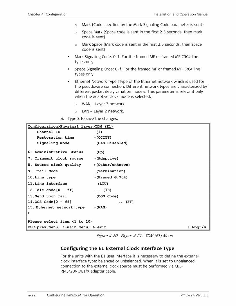
Chapter 4 Configuration Installation and Operation Manual
4-22 Configuring IPmux-24 for Operation IPmux-24 Ver. 1.5
Mark (Code specified by the Mark Signaling Code parameter is sent)
Space Mark (Space code is sent in the first 2.5 seconds, then mark code is sent)
Mark Space (Mark code is sent in the first 2.5 seconds, then space code is sent)
Mark Signaling Code: 0–f. For the framed MF or framed MF CRC4 line types only
Space Signaling Code: 0–f. For the framed MF or framed MF CRC4 line types only
Ethernet Network Type (Type of the Ethernet network which is used for the pseudowire connection. Different network types are characterized by different packet delay variation models. This parameter is relevant only when the adaptive clock mode is selected.)
WAN – Layer 3 network
LAN – Layer 2 network.
4. Type S to save the changes.
Configuration>Physical layer>TDM (E1) Channel ID (1) Restoration time >(CCITT) Signaling mode (CAS Disabled)
6. Administrative Status (Up)
7. Transmit clock source >(Adaptive)
8. Source clock quality >(Other/unknown)
9. Trail Mode (Termination)
10.Line type >(Framed G.704)
11.Line interface (LTU)
12.Idle code[0 - ff] ... (7E)
13.Send upon fail (OOS Code) 14.OOS Code[0 - ff] ... (FF) 15. Ethernet network type >(WAN) > Please select item <1 to 10> ESC-prev.menu; !-main menu; &-exit 1 Mngr/s
Figure 4-20. Figure 4-21. TDM (E1) Menu
Configuring the E1 External Clock Interface Type
For the units with the E1 user interface it is necessary to define the external clock interface type: balanced or unbalanced. When it is set to unbalanced, connection to the external clock source must be performed via CBL-RJ45/2BNC/E1/X adapter cable.

Installation and Operation Manual Chapter 4 Configuration
IPmux-24 Ver. 1.5 Configuring IPmux-24 for Operation 4-23
To configure the external clock E1 interface type:
• From the Physical Layer menu (Configuration > Physical Layer), select External Clock Interface and choose its type: balanced or unbalanced.
Configuring the T1 TDM Interface
The procedure for configuring the T1 port is similar to the procedure described above for configuring the E1 port.
To configure T1 interface:
1. From the TDM (T1) menu, type F to select one of the T1 links that you intend to configure.
2. From the TDM (T1) menu, configure the following:
Administrative Status:
Up (T1 link is enabled)
Down (T1 link is disabled)
Transmit clock source:
Adaptive (Clock is regenerated from a T1 bundle)
Loopback (T1 recovered Rx clock is used as the Tx clock)
Internal (Tx clock is received from an internal oscillator)
System (System clock is used as the Tx clock)
Source clock quality (Quality of the adaptive clock used by the device):
Stratum 1/PRC G.811
Stratum 2/Type II G.812
Stratum 3/Type IV G.812
Stratum 3E/Type III G.812
Other/Unknown
• The Source Clock Quality parameter is relevant only when the Tx clock source is set to adaptive or loopback.
• In adaptive clock mode only the Stratum 1/PRC G.811 and Stratum 2/Type II G.812 values are available when the Ethernet network type is set to LAN.
Rx sensitivity (Maximum attenuation of the receive signal that can be compensated for by the interface receive path):
Short haul (-10 dB)
Long haul (-32 dB)
Trail Mode (Enables the end-to-end transfer of TDM OAM (Operation, administration, and maintenance) data in framed mode, when the payload format is set to V2.
Termination (Trail mode is disabled; the TDM networks function as separate OAM domains)
Note

Chapter 4 Configuration Installation and Operation Manual
4-24 Configuring IPmux-24 for Operation IPmux-24 Ver. 1.5
Extension (Trail mode is enabled; OAM data is passed between the TDM networks)
Line type (T1 framing mode):
ESF (24 frames per multiframe)
SF (D4) (12 frames per multiframe)
Unframed
Line code (Line code and zero suppression method used by the port):
B7ZS
B8ZS
AMI
Line interface:
DSU (DSU interface)
CSU (CSU interface)
Line length (DSU mode only, length of a cable in feet between the IPmux-24 T1 port connector and the network access point):
0–133
133–266
266–399
399–533
533–655
Line buildOut (CSU mode only, Tx gain level relative to T1 output transmit level):
0 dB (No attenuation)
-7.5 dB (Attenuation of 7.5 dB relative to the nominal transmit level)
-15 dB (Attenuation of 15 dB relative to the nominal transmit level)
-22 dB (Attenuation of 22 dB relative to the nominal transmit level)
Restoration time (Time required for the T1 port to return to normal operation after sync loss):
TR-6211 (10 seconds)
Fast (1 second)
Idle Code (code transmitted to fill unused timeslots in the T1 frames): 0 to ff.
Send Upon Fail (Notification sent to the T1 side if Ethernet link fails):
OOS Code (Out-of-service code)
AIS (Alarm indication signal)
OOS code (Code to be sent to the T1 side if Ethernet link fails): 0–ff
Installation and Operation Manual Chapter 4 Configuration
IPmux-24 Ver. 1.5 Configuring IPmux-24 for Operation 4-25
Signaling mode:
None
Robbed Bit
OOS signaling (Out-of-service signaling method. OOS signal is sent toward the IP path when loss of signal, loss of frame, or AIS is detected at the T1 line. The OOS signal is also sent toward the T1 line when packet receive buffer overrun or underrun occurs.):
Space (Code specified by the Space Signaling Code parameter is sent)
Mark (Code specified by the Mark Signaling Code parameter is sent)
Space MARK (space code is sent in the first 2.5 seconds, then mark code is sent)
Mark Space (Mark code is sent in the first 2.5 seconds, then space code is sent)
Mark Signaling Code:
0–f for ESF framing
0–3 for SF framing
Space Signaling Code:
0–f for ESF framing
0–3 for SF framing
Ethernet Network Type (Type of the Ethernet network which is used for the pseudowire connection. Different network types are characterized by different packet delay variation models. This parameter is relevant only when the adaptive clock mode is selected.)
WAN – Layer 3 network
LAN – Layer 2 network.

Chapter 4 Configuration Installation and Operation Manual
4-26 Configuring IPmux-24 for Operation IPmux-24 Ver. 1.5
Configuration>Physical layer>TDM (T1) Channel ID (1) 1. Administrative status (Up) 2. Transmit clock source >(Adaptive) 3. Source clock quality >(Other/unknown) 4. Rx Sensitivity (Short haul) 5. Trail Mode (Termination) 6. Line type >(ESF) 7. Line code >(B8ZS) 8. Line interface >(DSU) 9. Line length (feet) >(0-133) 10. Restoration time >(TR-621 (10 seconds)) 11. Idle Code[0 - ff] ... (7E) 12. Send upon fail (OOS Code) 13. OOS code[0 - ff] ... (FF) 14. Signaling mode (Robbed Bit) 15. OOS signaling > (Space) 16.Mark signaling code[0 - f] ... (D) 17.Space signaling code[0 - f] ... (1) 18.Ethernet network type > (Wan) > Please select item <1 to 18> ESC-prev.menu; !-main menu; &-exit 1 Mngr/s
Figure 4-22. TDM (T1) Menu
Configuring Ethernet Interfaces
IPmux-24 includes one network and up to two user Ethernet ports.
To configure Ethernet interface:
1. From the Physical Layer menu (Figure 4-18), select ETH.
The ETH menu appears (see Figure 4-23).
2. From the ETH menu, type F to select the Ethernet interface that you intend to configure (Network ETH1, Network/User ETH2 or User ETH3).
3. When the required Ethernet interface is displayed, configure the following:
Administrative status:
Up (Current Ethernet interface is enabled)
Down (Current Ethernet interface is disabled)
Auto negotiation:
Enable (Autonegotiation is enabled)
Disable (Autonegotiation is disabled)
Installation and Operation Manual Chapter 4 Configuration
IPmux-24 Ver. 1.5 Configuring IPmux-24 for Operation 4-27
Max capability advertised (Maximum capability to be advertised during the autonegotiation process):
10BaseT Half Duplex
10BaseT Full Duplex
100BaseT Half Duplex
100BaseT Full Duplex
1000BaseX Full Duplex
Default type (Rate and duplex mode, if the autonegotiation is disabled):
10BaseT Half Duplex
10BaseT Full Duplex
100BaseT Half Duplex
100BaseT Full Duplex
1000BaseX Full Duplex
• When autonegotiation protocols do not support each other, this degrades the connection to a half-duplex mode. In order to avoid this, disable autonegotiation and configure the ports manually. Half-duplex degradation also occurs when autonegotiation is enabled at one port and disabled at the opposite port.
• Half-duplex operation in the IPmux-24 network port is not recommended when transmitting small-size packets, because collisions and backoffs cause large delay variation and may exceed the delay variation buffer tolerance at the receiving end, resulting in buffer underflows and errors.
Flow Control (Data flow control method based on Ethernet Pause frames. IPmux-24 only responds to the Pause frames sent by the peer device, slowing its transmission rate.):
Enable (Flow control is enabled)
Disable (Flow control is disabled)
Enabling flow control may cause deterioration in the clock and voice traffic quality.
4. Type S to save your changes.
Notes
Note
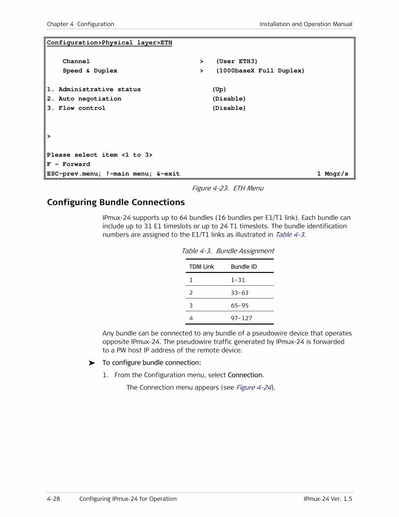
Chapter 4 Configuration Installation and Operation Manual
4-28 Configuring IPmux-24 for Operation IPmux-24 Ver. 1.5
Configuration>Physical layer>ETH Channel > (User ETH3) Speed & Duplex > (1000baseX Full Duplex) 1. Administrative status (Up) 2. Auto negotiation (Disable) 3. Flow control (Disable) > Please select item <1 to 3> F – Forward ESC-prev.menu; !-main menu; &-exit 1 Mngr/s
Figure 4-23. ETH Menu
Configuring Bundle Connections
IPmux-24 supports up to 64 bundles (16 bundles per E1/T1 link). Each bundle can include up to 31 E1 timeslots or up to 24 T1 timeslots. The bundle identification numbers are assigned to the E1/T1 links as illustrated in Table 4-3.
Table 4-3. Bundle Assignment
TDM Link Bundle ID
1 1–31
2 33–63
3 65–95
4 97–127
Any bundle can be connected to any bundle of a pseudowire device that operates opposite IPmux-24. The pseudowire traffic generated by IPmux-24 is forwarded to a PW host IP address of the remote device.
To configure bundle connection:
1. From the Configuration menu, select Connection.
The Connection menu appears (see Figure 4-24).
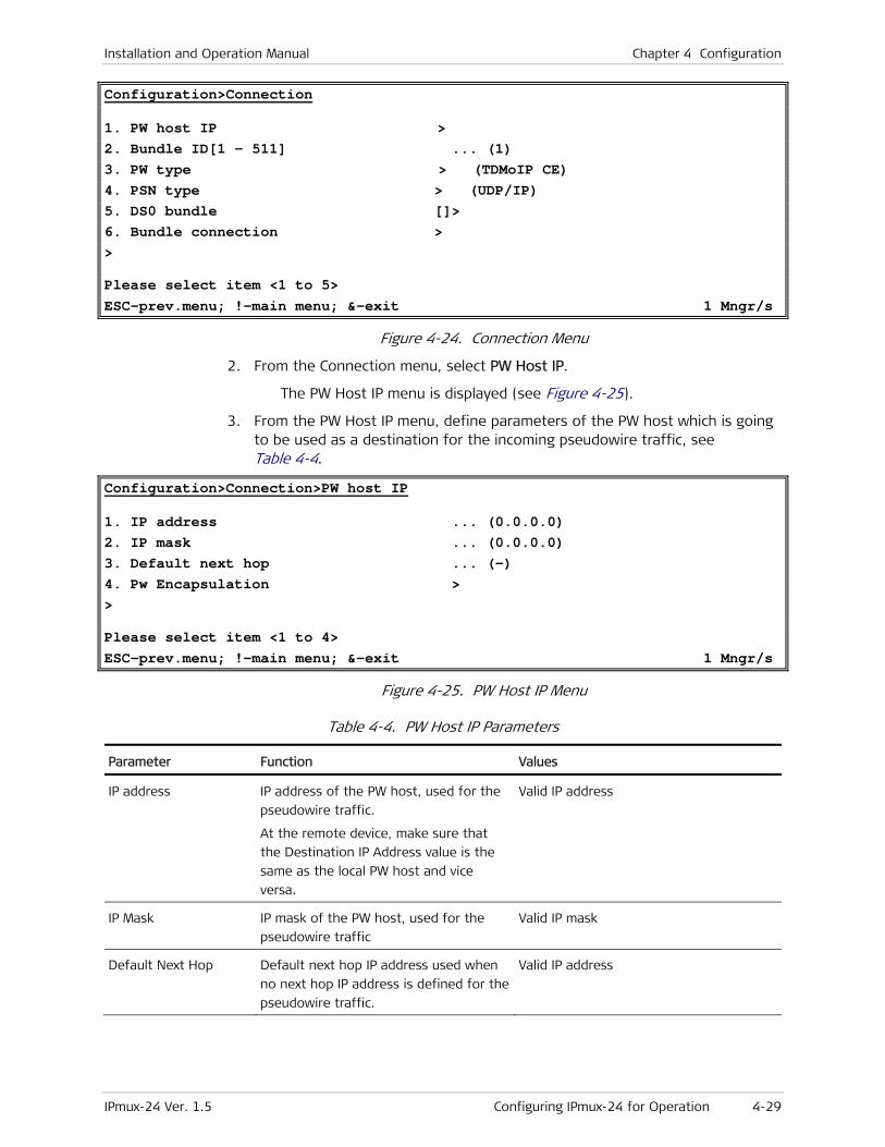
Installation and Operation Manual Chapter 4 Configuration
IPmux-24 Ver. 1.5 Configuring IPmux-24 for Operation 4-29
Configuration>Connection
1. PW host IP > 2. Bundle ID[1 - 511] ... (1) 3. PW type > (TDMoIP CE) 4. PSN type > (UDP/IP) 5. DS0 bundle []> 6. Bundle connection > > Please select item <1 to 5> ESC-prev.menu; !-main menu; &-exit 1 Mngr/s
Figure 4-24. Connection Menu
2. From the Connection menu, select PW Host IP.
The PW Host IP menu is displayed (see Figure 4-25).
3. From the PW Host IP menu, define parameters of the PW host which is going to be used as a destination for the incoming pseudowire traffic, see Table 4-4.
Configuration>Connection>PW host IP
1. IP address ... (0.0.0.0) 2. IP mask ... (0.0.0.0) 3. Default next hop ... (-) 4. Pw Encapsulation > > Please select item <1 to 4> ESC-prev.menu; !-main menu; &-exit 1 Mngr/s
Figure 4-25. PW Host IP Menu
Table 4-4. PW Host IP Parameters
Parameter Function Values
IP address IP address of the PW host, used for the
pseudowire traffic.
At the remote device, make sure that
the Destination IP Address value is the
same as the local PW host and vice
versa.
Valid IP address
IP Mask IP mask of the PW host, used for the
pseudowire traffic
Valid IP mask
Default Next Hop Default next hop IP address used when
no next hop IP address is defined for the
pseudowire traffic.
Valid IP address
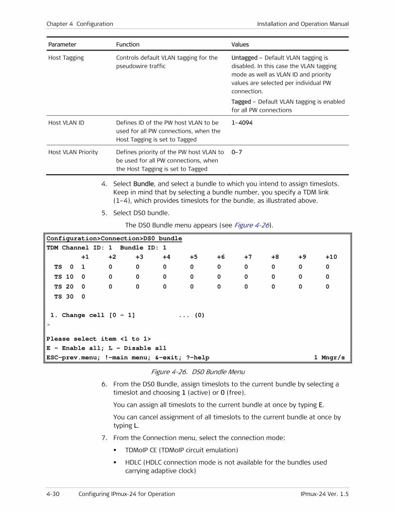
Chapter 4 Configuration Installation and Operation Manual
4-30 Configuring IPmux-24 for Operation IPmux-24 Ver. 1.5
Parameter Function Values
Host Tagging Controls default VLAN tagging for the
pseudowire traffic
Untagged – Default VLAN tagging is
disabled. In this case the VLAN tagging
mode as well as VLAN ID and priority
values are selected per individual PW
connection.
Tagged – Default VLAN tagging is enabled
for all PW connections
Host VLAN ID Defines ID of the PW host VLAN to be
used for all PW connections, when the
Host Tagging is set to Tagged
1–4094
Host VLAN Priority Defines priority of the PW host VLAN to
be used for all PW connections, when
the Host Tagging is set to Tagged
0–7
4. Select Bundle, and select a bundle to which you intend to assign timeslots. Keep in mind that by selecting a bundle number, you specify a TDM link (1–4), which provides timeslots for the bundle, as illustrated above.
5. Select DS0 bundle.
The DS0 Bundle menu appears (see Figure 4-26).
Configuration>Connection>DS0 bundle TDM Channel ID: 1 Bundle ID: 1 +1 +2 +3 +4 +5 +6 +7 +8 +9 +10
TS 0 1 0 0 0 0 0 0 0 0 0
TS 10 0 0 0 0 0 0 0 0 0 0
TS 20 0 0 0 0 0 0 0 0 0 0
TS 30 0 1. Change cell [0 - 1] ... (0) > Please select item <1 to 1> E – Enable all; L – Disable all ESC-prev.menu; !-main menu; &-exit; ?-help 1 Mngr/s
Figure 4-26. DS0 Bundle Menu
6. From the DS0 Bundle, assign timeslots to the current bundle by selecting a timeslot and choosing 1 (active) or 0 (free).
You can assign all timeslots to the current bundle at once by typing E.
You can cancel assignment of all timeslots to the current bundle at once by typing L.
7. From the Connection menu, select the connection mode:
TDMoIP CE (TDMoIP circuit emulation)
HDLC (HDLC connection mode is not available for the bundles used carrying adaptive clock)

Installation and Operation Manual Chapter 4 Configuration
IPmux-24 Ver. 1.5 Configuring IPmux-24 for Operation 4-31
CESoPSN (CESoPSN connection mode is available for E1/T1 links operating in framed mode)
SAToP (SAToP connection mode is available for E1/T1 links operating in unframed mode)
8. From the Connection menu, configure the packet-switched network type:
UDP/IP (Bundle encapsulation is UDP/IP)
MPLS/ETH (Bundle encapsulation is MPLS/Ethernet)
PSN Type is only available after Bundle ID has been set.
9. From the Connection menu, select Bundle connection.
The Bundle Connection menu appears (see Figure 4-27).
IPmux-24 only shows the relevant menu options, depending on the TDM line type, PW type, PSN type, and transmit clock source.
Configuration>Connection>Bundle connection TDM channel ID: 1 Bundle ID: 1 1. Destination IP address ... (0.0.0.0) 2. Next hop ... (0.0.0.0) 3. IP TOS[0 - 255] ... (0) 4. Connection status (Enable) 5. Destination bundle[1 - 8063] ... (1) 6. TDM bytes in frame(x48 bytes)[1 - 30] ... (1) 7. Payload format (V2) 8. Far end type > (E1) 9. OAM connectivity (Disable) 10. Jitter buffer [msec][2.5 - 200] ... (200) 11. Sensitive (Data) 12. OOS mode (Tx OOS) 13. VLAN tagging (Enable) 14. VLAN ID[1 - 4095] ... (1) 15. VLAN priority[0 - 7] ... (7) > Please select item <1 to 15> F - Forward Bundle ID; D - Delete; ? - Help ESC-prev.menu; !-main menu; &-exit
Figure 4-27. Bundle Connection Menu (Connection Mode=TDMoIP CE, PSN Type=UDP/IP)
10. From the Bundle Connection menu, configure the connection values according to Table 4-5, Table 4-6, Table 4-7, Table 4-8, Table 4-9, Table 4-10, Table 4-11, Table 4-12.
Note
Note

Chapter 4 Configuration Installation and Operation Manual
4-32 Configuring IPmux-24 for Operation IPmux-24 Ver. 1.5
Table 4-5. Connection Parameters (TDMoIP CE Connection, UDP/IP PSN)
Parameter Function Values
Destination IP Address IP address of the destination device Vald IP address
Next Hop Use the next hop parameter when the
destination IP address is not in the
device subnet. In such cases the
Ethernet frame is sent to the next hop
IP. If it is not configured, the default
gateway is used.
Vald IP address
IP TOS Specifies the Layer 3 priority assigned to
the traffic generated by this bundle.
For IP networks, this priority is indicated
by the IP type-of-service parameter for
this bundle. The specified value is
inserted in the IP TOS field of the bundle
IP packets.
When supported by an IP network, the
type-of-service parameter is interpreted,
in accordance with RFC 791 or RFC 2474,
as a set of qualitative parameters for the
precedence, delay, throughput and
delivery reliability to be provided to the
IP traffic generated by this bundle.
These qualitative parameters may be
used by each network that transfers the
bundle IP traffic to select specific values
for the actual service parameters of the
network, to achieve the desired quality
of service
You can also specify a Layer 2 priority by
means of the VLAN Priority field,
provided VLAN Tagging for this bundle is
Enable.
0–255
In accordance with RFC 2474, it is
recommended to use only values which
are multiples of 4.
Connection Status Administrative status of the connection Enable – Connection is active
Disable –The connective is not active. You
can still configure and save the desired
parameters, to prepare the bundle for
activation when needed.

Installation and Operation Manual Chapter 4 Configuration
IPmux-24 Ver. 1.5 Configuring IPmux-24 for Operation 4-33
Parameter Function Values
Destination Bundle Bundle number in the destination device.
IPmux-24 automatically adds the
following values to the destination and
source bundle number:
• +15, when the PSN type is set to
MPLS
• +0xc000 when the CESoPSN and
SAToP PWs operate over UDP/IP PSN
• +1 when the TDMoIP is set to the V1
payload format.
1–8063
TDM Bytes in Frame
(x48 bytes)
UDP payload length, enabling reduction
of Ethernet throughput
1–30
Payload Format Selects the TDMoIP payload format.
The selection must be compatible with
the equipment at the far end of the
connection. The payload format is valid
for TDMoIP CE PWs and UDP/IP PSNs.
V1 – Old TDMoIP format, defined as
experimental in the relevant IETF drafts.
Not recommended for use.
TDMoIP version V1 requires two UDP
sockets per bundle, whereas TDMoIP V2
requires a single UDP socket per bundle.
The larger number of UDP sockets per
bundle needed by TDMoIP V1 reduces the
maximum number of bundles to a given
destination supported by IPmux-24.
V2 – Current TDMoIP format. Requires one
UDP socket per bundle.
Far end type Specifies the type of framing used by
the equipment at the destination
endpoint. The selected value also
determines the encoding law used on
PCM voice channels.
Make sure to select the same value at
both end points. The selected value
must also match the Line Type
configured for the physical port of the
bundle local endpoint.
E1 – E1 stream with G.704 framing. The
PCM signals are processed assuming that
they are encoded in accordance with the
A-law. You can use this selection when
the port Line Type is a FRAMED version.
T1 ESF – T1 stream with ESF framing. The
PCM signals are processed assuming that
they are encoded in accordance with the
μ-law.
T1 (SF) – T1 stream with SF (D4) framing.
The PCM signals are processed assuming
that they are encoded in accordance with
the μ-law.
Unframed/serial – unframed data stream,
transparently transferred. You can use
this selection when the port Line Type is
unframed.

Chapter 4 Configuration Installation and Operation Manual
4-34 Configuring IPmux-24 for Operation IPmux-24 Ver. 1.5
Parameter Function Values
OAM connectivity Controls the use of the OAM connectivity
protocol for this bundle.
The OAM connectivity protocol enables
detecting loss of communication with
the destination of TDMoIP traffic and
taking steps that prevent the resulting
flooding. The protocol also enables
checking that the destination uses a
compatible configuration.
The selection must be compatible with
the equipment at the far end of the
connection.
ENABLE – The use of the OAM
connectivity protocol is enabled. This is
the recommended selection. Make sure to
select V2 for Payload Format.
DISABLE – The use of the OAM
connectivity protocol is disabled.
Jitter Buffer Specifies the value of the jitter buffer to
be used on this bundle.
You should use the shortest feasible
buffer, to minimize connection latency.
2.5–180 msec (framed)
0.5–180 msec (unframed)
Sensitive Specifies whether to optimize the clock
for accurateness or for constant delay
Data – Accurate clock is more important
than constant delay
Delay – Constant delay is more important
than accurate clock
OOS Mode Defines whether Out of Service (OOS)
signal is transmitted. The OOS signal is
sent toward the IP path when loss of
signal, loss of frame, or AIS is detected
at the TDM line.
Tx OOS – OOS transmission is enabled
OOS suppression – OOS transmission is
disabled
VLAN Tagging Controls the use of VLAN tagging for the
traffic generated by this bundle
Enable – VLAN tagging is enabled.
Disable – VLAN tagging is disabled.
VLAN ID When VLAN tagging is enabled, specifies
the VLAN ID number used by the bundle
traffic sent through this port.
When VLAN tagging is disabled, this
parameter is not displayed
1 to 4094
0 means that no VLAN ID has been
specified.
VLAN Priority When VLAN tagging is enabled, specifies
the priority assigned to the bundle
traffic using the selected VLAN.
When VLAN tagging is disabled, this
parameter is not displayed
0–7

Installation and Operation Manual Chapter 4 Configuration
IPmux-24 Ver. 1.5 Configuring IPmux-24 for Operation 4-35
Table 4-6. Connection Parameters (TDMoIP CE Connection, MPLS/ETH PSN)
Parameter Function Values
Destination IP Address See Table 4-5
Outbound Label
Tagging
Controls the use of an interworking
MPLS label for the transmit (outbound)
direction of the bundle. Network
termination units, such as IPmux-24,
ignore the outbound label.
Enable – Outbound tagging is enabled.
Disable – Outbound tagging is disabled.
Outbound Tunnel Label Specifies the outbound MPLS label used
for the bundle.
This parameter is displayed only when
Outbound Label Tagging is enabled.
16–1048575. 0 means that no label has
been defined.
Outbound EXP Bits Specifies the value of the outbound EXP
bits in the packet header used for the
bundle.
This parameter is displayed only when
Outbound Label Tagging is enabled.
0–7
Connection Status See Table 4-5
Destination Bundle See Table 4-5
Next Hop Type Type of the next hop device IP – The next hop device is an IP router
MAC – The next hop device is an MPLS LER
Next Hop See Table 4-5
TDM Bytes in Frame
(x48 bytes)
See Table 4-5
Payload Format See Table 4-5
Far End Type See Table 4-5
OAM Connectivity See Table 4-5
Jitter Buffer See Table 4-5
Sensitive See Table 4-5
OOS Mode See Table 4-5
VLAN Tagging See Table 4-5
VLAN ID See Table 4-5
Table 4-7. Connection Parameters (CESoPSN Connection, UDP/IP PSN)
Parameter Function Values
Destination IP Address See Table 4-5
Next Hop See Table 4-5
IP TOS See Table 4-5

Chapter 4 Configuration Installation and Operation Manual
4-36 Configuring IPmux-24 for Operation IPmux-24 Ver. 1.5
Parameter Function Values
Connection Status See Table 4-5
Destination bundle See Table 4-5
TDM Frames in Packet Defines number of TDM frames in one
packet
4–57
Payload Format See Table 4-5
OAM connectivity See Table 4-5
Jitter Buffer See Table 4-5
Sensitive See Table 4-5
OOS Mode See Table 4-5
VLAN Tagging See Table 4-5
VLAN ID See Table 4-5
VLAN Priority See Table 4-5
Table 4-8. Connection Parameters (CESoPSN Connection, MPLS/ETH PSN)
Parameter Function Values
Destination IP Address See Table 4-5
Outbound Label
Tagging
See Table 4-6
Outbound Tunnel Label See Table 4-6
Outbound EXP Bits See Table 4-6
Connection Status See Table 4-5
Destination Bundle See Table 4-5
Next Hop Type See Table 4-6
Next Hop See Table 4-5
TDM Frames in Packet See Table 4-7
Payload Format See Table 4-5
Far End Type See Table 4-5
OAM Connectivity See Table 4-5
Jitter Buffer See Table 4-5
Sensitive See Table 4-5
OOS Mode See Table 4-5
VLAN Tagging See Table 4-5
VLAN ID See Table 4-5
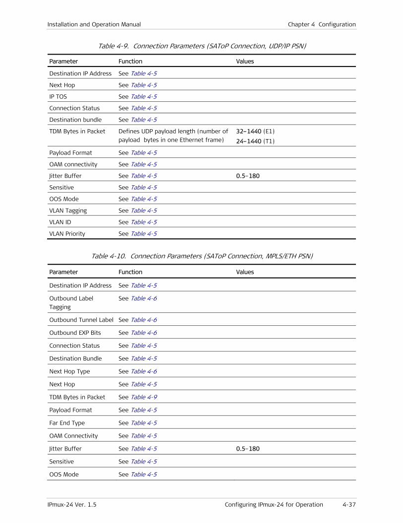
Installation and Operation Manual Chapter 4 Configuration
IPmux-24 Ver. 1.5 Configuring IPmux-24 for Operation 4-37
Table 4-9. Connection Parameters (SAToP Connection, UDP/IP PSN)
Parameter Function Values
Destination IP Address See Table 4-5
Next Hop See Table 4-5
IP TOS See Table 4-5
Connection Status See Table 4-5
Destination bundle See Table 4-5
TDM Bytes in Packet Defines UDP payload length (number of
payload bytes in one Ethernet frame)
32–1440 (E1)
24–1440 (T1)
Payload Format See Table 4-5
OAM connectivity See Table 4-5
Jitter Buffer See Table 4-5 0.5–180
Sensitive See Table 4-5
OOS Mode See Table 4-5
VLAN Tagging See Table 4-5
VLAN ID See Table 4-5
VLAN Priority See Table 4-5
Table 4-10. Connection Parameters (SAToP Connection, MPLS/ETH PSN)
Parameter Function Values
Destination IP Address See Table 4-5
Outbound Label
Tagging
See Table 4-6
Outbound Tunnel Label See Table 4-6
Outbound EXP Bits See Table 4-6
Connection Status See Table 4-5
Destination Bundle See Table 4-5
Next Hop Type See Table 4-6
Next Hop See Table 4-5
TDM Bytes in Packet See Table 4-9
Payload Format See Table 4-5
Far End Type See Table 4-5
OAM Connectivity See Table 4-5
Jitter Buffer See Table 4-5 0.5–180
Sensitive See Table 4-5
OOS Mode See Table 4-5
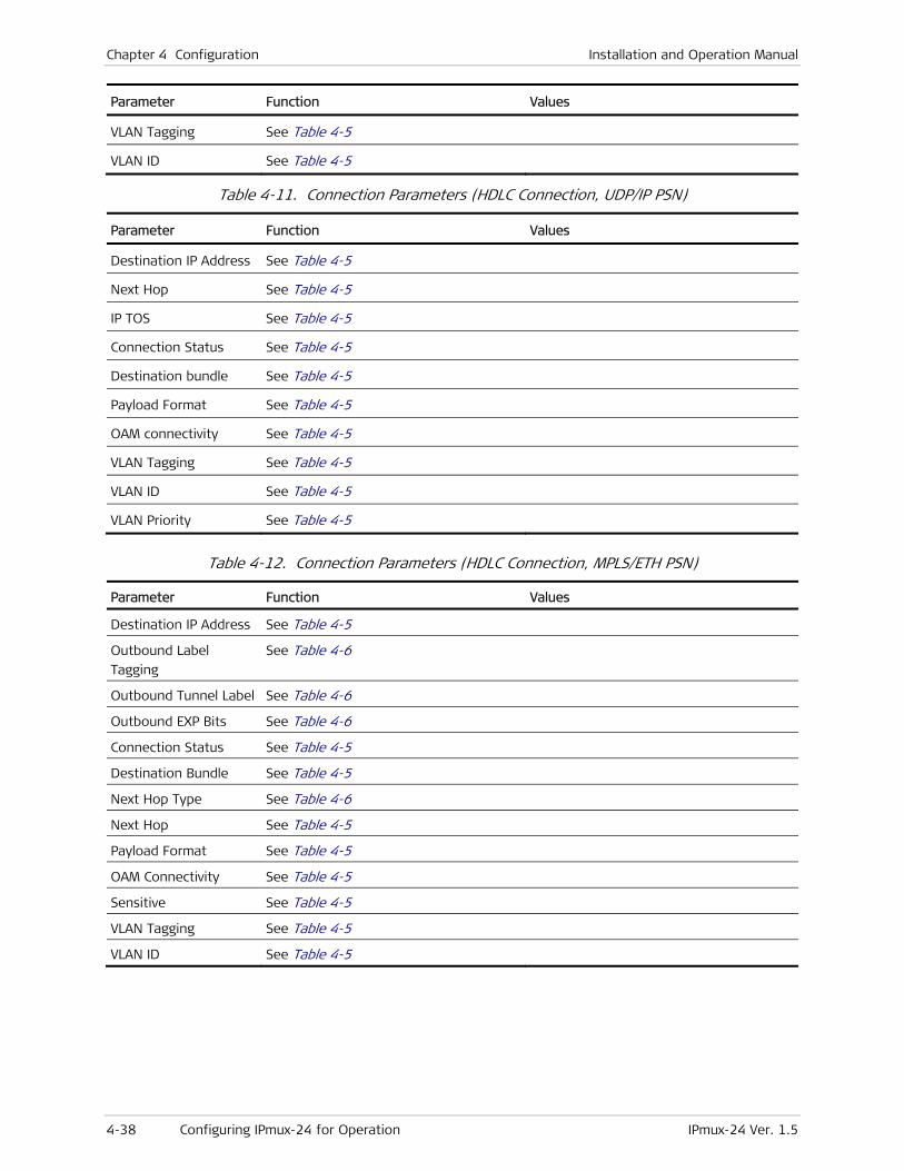
Chapter 4 Configuration Installation and Operation Manual
4-38 Configuring IPmux-24 for Operation IPmux-24 Ver. 1.5
Parameter Function Values
VLAN Tagging See Table 4-5
VLAN ID See Table 4-5
Table 4-11. Connection Parameters (HDLC Connection, UDP/IP PSN)
Parameter Function Values
Destination IP Address See Table 4-5
Next Hop See Table 4-5
IP TOS See Table 4-5
Connection Status See Table 4-5
Destination bundle See Table 4-5
Payload Format See Table 4-5
OAM connectivity See Table 4-5
VLAN Tagging See Table 4-5
VLAN ID See Table 4-5
VLAN Priority See Table 4-5
Table 4-12. Connection Parameters (HDLC Connection, MPLS/ETH PSN)
Parameter Function Values
Destination IP Address See Table 4-5
Outbound Label
Tagging
See Table 4-6
Outbound Tunnel Label See Table 4-6
Outbound EXP Bits See Table 4-6
Connection Status See Table 4-5
Destination Bundle See Table 4-5
Next Hop Type See Table 4-6
Next Hop See Table 4-5
Payload Format See Table 4-5
OAM Connectivity See Table 4-5
Sensitive See Table 4-5
VLAN Tagging See Table 4-5
VLAN ID See Table 4-5

Installation and Operation Manual Chapter 4 Configuration
IPmux-24 Ver. 1.5 Configuring IPmux-24 for Operation 4-39
• When PSN Type is MPLS/ETH the payload format is always V2.
• Make sure that selected VLAN is configured as a member of the network port VLANs (see Configuring the Ethernet Bridge below).
• When VLAN Tagging is enabled, IPmux-24 checks for matching VLAN ID on transmitted frames only; frames received with a non-matching VLAN ID will not be dropped.
• IPmux-24 assigns internal bundle numbers that are normally transparent to the end user. However, in case you create bundle connections that mix together different types of payload formats or PSN types, then the internal bundle numbering scheme may need to be understood in order to prevent conflicts that would be visible as bit errors. The internal bundle number (IBN) is assigned in the following manner: V1: IBN = Bundle ID; V2: IBN = Bundle ID + 1; MPLS: IBN = Bundle ID + 15. Bundle IDs must be assigned in a manner that the internal bundle numbers are unique.
Configuring the Ethernet Bridge
The IPmux-24 bridge connects Ethernet ports of the unit. The bridge operates in the VLAN-aware and VLAN-unaware modes. Learning and filtering can be enabled or disabled. Static MAC addresses are stored in the MAC table. Each bridge port can be assigned to a VLAN.
To configure the bridge:
1. From the Configuration menu, select Bridge.
The Bridge menu is displayed (see Figure 4-28).
2. From the Bridge menu, configure the following:
VLAN Mode:
Aware (IPmux-24 bridge handles VLANs)
Unaware (IPmux-24 bridge does not handle VLANs)
Forwarding Mode (Operation mode of the bridge):
Transparent (No filtering is performed. IPmux-24 forwards all received frames.)
Filter (IPmux-24 filters traffic according the received MAC addresses)
Aging Time (Amount of time a LAN node (station) is allowed to be inactive before it is removed from the network): 300 to 3600 seconds.
Notes

Chapter 4 Configuration Installation and Operation Manual
4-40 Configuring IPmux-24 for Operation IPmux-24 Ver. 1.5
Configuration>Bridge
1. VLAN Mode (Unaware) 2. Forwarding Mode (Transparent) 3. Aging Time[300 - 4080] ...(300) 4. Static MAC Table []> 5. Erase MAC Table 6. Bridge Port > 7. VLAN Membership > ESC-prev.menu; !-main menu; &-exit 1 Mngr/s
Figure 4-28. Bridge Menu
Configuring MAC Table
You can add static MAC addresses to the IPmux-24 MAC table. When the bridge operates in the VLAN-aware mode, it is possible to assign VLAN ID to a MAC address.
To add a static MAC addresses:
1. From the Bridge menu, select Static MAC Table.
The Static MAC Table appears (see Figure 4-29).
2. From the Static MAC Table, type A to add a static MAC address.
The Static MAC Table display changes, entering the Add mode (see Figure 4-31).
3. When in Add mode, perform the following:
Select MAC Address, and enter a new MAC address.
Select Received Bridge Port, and choose an IPmux-24 interface this MAC address will be attached to.
If the bridge operates in the VLAN-aware mode, specify VLAN ID with which frames from the current MAC address are expected to arrive.
Save the changes.
Press <Esc> to return to the Static MAC Table.
To remove a static address from the table:
• From the Static MAC Table (Figure 4-29), select a MAC address that you want to remove and type R.
The static MAC address is deleted from the table.
To delete static addresses from the MAC table:
1. From the Static MAC Table (Figure 4-29), type C to delete all static MAC addresses.
IPmux-24 displays the following message: Are you sure??? (Y/N)
2. Type Y to confirm deletion of all static MAC addresses from the table.
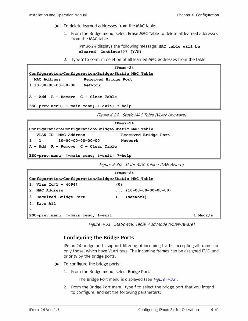
Installation and Operation Manual Chapter 4 Configuration
IPmux-24 Ver. 1.5 Configuring IPmux-24 for Operation 4-41
To delete learned addresses from the MAC table:
1. From the Bridge menu, select Erase MAC Table to delete all learned addresses from the MAC table.
IPmux-24 displays the following message: MAC table will be cleared. Continue??? (Y/N)
2. Type Y to confirm deletion of all learned MAC addresses from the table.
IPmux-24 Configuration>Configuration>Bridge>Static MAC Table MAC Address Received Bridge Port 1 10-00-00-00-00-00 Network A - Add R – Remove C - Clear Table ESC-prev.menu; !-main menu; &-exit; ?-help
Figure 4-29. Static MAC Table (VLAN-Unaware)
IPmux-24 Configuration>Configuration>Bridge>Static MAC Table VLAN ID MAC Address Received Bridge Port 1 1 10-00-00-00-00-00 Network A - Add R – Remove C - Clear Table ESC-prev.menu; !-main menu; &-exit; ?-help
Figure 4-30. Static MAC Table (VLAN-Aware)
IPmux-24 Configuration>Configuration>Bridge>Static MAC Table 1. Vlan Id[1 - 4094] (0) 2. MAC Address ... (10-00-00-00-00-00)
3. Received Bridge Port > (Network)
4. Save All > ESC-prev.menu; !-main menu; &-exit 1 Mngr/s
Figure 4-31. Static MAC Table, Add Mode (VLAN-Aware)
Configuring the Bridge Ports
IPmux-24 bridge ports support filtering of incoming traffic, accepting all frames or only those, which have VLAN tags. The incoming frames can be assigned PVID and priority by the bridge ports.
To configure the bridge ports:
1. From the Bridge menu, select Bridge Port.
The Bridge Port menu is displayed (see Figure 4-32).
2. From the Bridge Port menu, type f to select the bridge port that you intend to configure, and set the following parameters:
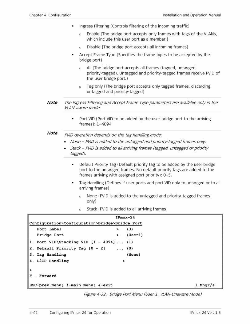
Chapter 4 Configuration Installation and Operation Manual
4-42 Configuring IPmux-24 for Operation IPmux-24 Ver. 1.5
Ingress Filtering (Controls filtering of the incoming traffic)
Enable (The bridge port accepts only frames with tags of the VLANs, which include this user port as a member.)
Disable (The bridge port accepts all incoming frames)
Accept Frame Type (Specifies the frame types to be accepted by the bridge port)
All (The bridge port accepts all frames (tagged, untagged, priority-tagged). Untagged and priority-tagged frames receive PVID of the user bridge port.)
Tag only (The bridge port accepts only tagged frames, discarding untagged and priority-tagged)
The Ingress Filtering and Accept Frame Type parameters are available only in the VLAN-aware mode.
Port VID (Port VID to be added by the user bridge port to the arriving frames): 1–4094
PVID operation depends on the tag handling mode:
• None – PVID is added to the untagged and priority-tagged frames only.
• Stack – PVID is added to all arriving frames (tagged, untagged or priority tagged).
Default Priority Tag (Default priority tag to be added by the user bridge port to the untagged frames. No default priority tags are added to the frames arriving with assigned port priority): 0–5.
Tag Handling (Defines if user ports add port VID only to untagged or to all arriving frames)
None (PVID is added to the untagged and priority-tagged frames only)
Stack (PVID is added to all arriving frames)
IPmux-24 Configuration>Configuration>Bridge>Bridge Port Port Label > (3) Bridge Port > (User1)
1. Port VID\Stacking VID [1 - 4094] ... (1) 2. Default Priority Tag [0 - 2] ... (0)
3. Tag Handling (None)
4. L2CP Handling > > F - Forward ESC-prev.menu; !-main menu; &-exit 1 Mngr/s
Figure 4-32. Bridge Port Menu (User 1, VLAN-Unaware Mode)
Note
Note
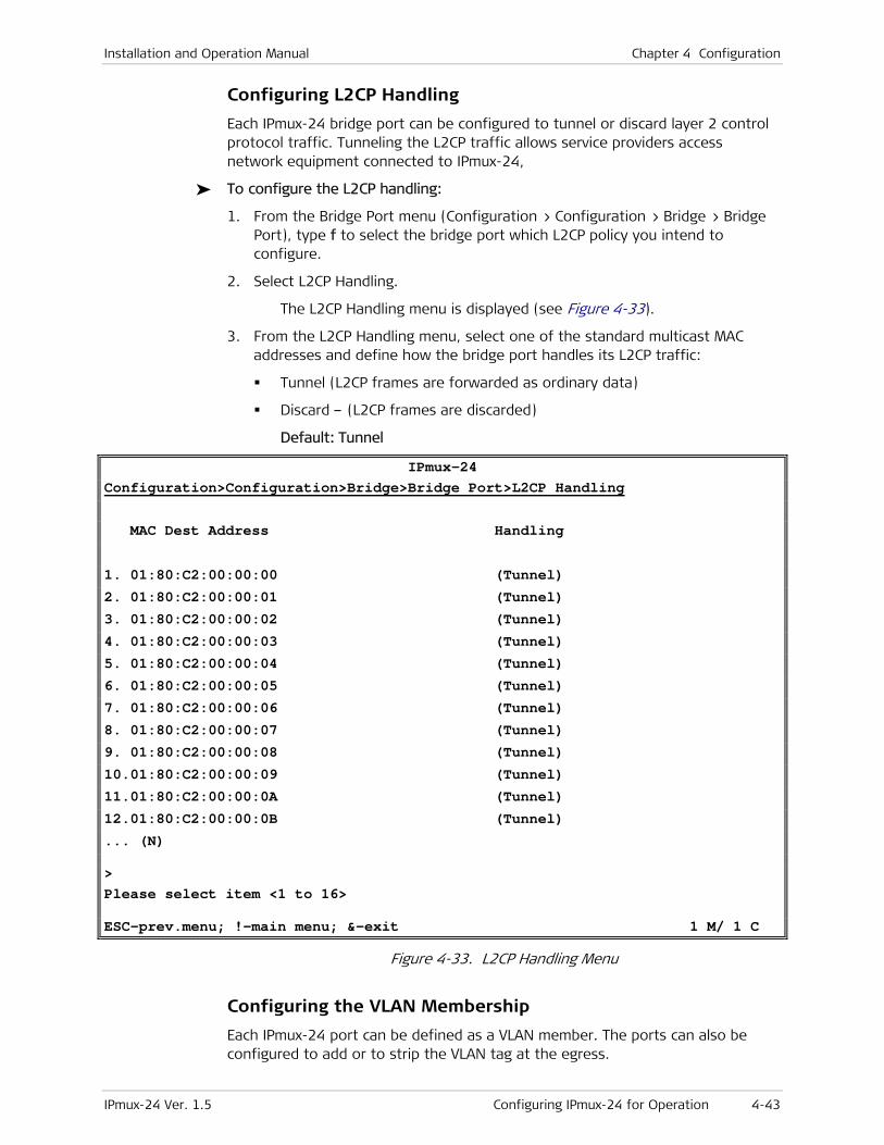
Installation and Operation Manual Chapter 4 Configuration
IPmux-24 Ver. 1.5 Configuring IPmux-24 for Operation 4-43
Configuring L2CP Handling
Each IPmux-24 bridge port can be configured to tunnel or discard layer 2 control protocol traffic. Tunneling the L2CP traffic allows service providers access network equipment connected to IPmux-24,
To configure the L2CP handling:
1. From the Bridge Port menu (Configuration > Configuration > Bridge > Bridge Port), type f to select the bridge port which L2CP policy you intend to configure.
2. Select L2CP Handling.
The L2CP Handling menu is displayed (see Figure 4-33).
3. From the L2CP Handling menu, select one of the standard multicast MAC addresses and define how the bridge port handles its L2CP traffic:
Tunnel (L2CP frames are forwarded as ordinary data)
Discard – (L2CP frames are discarded)
Default: Tunnel
IPmux-24 Configuration>Configuration>Bridge>Bridge Port>L2CP Handling
MAC Dest Address Handling
1. 01:80:C2:00:00:00 (Tunnel) 2. 01:80:C2:00:00:01 (Tunnel) 3. 01:80:C2:00:00:02 (Tunnel) 4. 01:80:C2:00:00:03 (Tunnel) 5. 01:80:C2:00:00:04 (Tunnel) 6. 01:80:C2:00:00:05 (Tunnel) 7. 01:80:C2:00:00:06 (Tunnel) 8. 01:80:C2:00:00:07 (Tunnel) 9. 01:80:C2:00:00:08 (Tunnel) 10.01:80:C2:00:00:09 (Tunnel)
11.01:80:C2:00:00:0A (Tunnel)
12.01:80:C2:00:00:0B (Tunnel)
... (N) > Please select item <1 to 16> ESC-prev.menu; !-main menu; &-exit 1 M/ 1 C
Figure 4-33. L2CP Handling Menu
Configuring the VLAN Membership
Each IPmux-24 port can be defined as a VLAN member. The ports can also be configured to add or to strip the VLAN tag at the egress.

Chapter 4 Configuration Installation and Operation Manual
4-44 Configuring IPmux-24 for Operation IPmux-24 Ver. 1.5
To configure the VLAN membership:
1. From the Bridge menu, select VLAN Membership.
The VLAN Membership menu is displayed (see Figure 4-34).
2. From VLAN Membership menu, type a and add a new VLAN, and enter the new VLAN number or type f to select an existing VLAN, to which you intend to assign the IPmux-24 port.
3. When the number of the required VLAN is displayed at the top of the menu, do the following:
Select Egress Tagged Ports to assign network and/or user ports to be the tagged members of the current VLAN. These ports add the current VLAN tag to all frames at egress.
Select Egress Untagged Ports to assign network and/or user ports to be the untagged members of the current VLAN. These ports strip the current VLAN tag from all frames at egress.
Each port can be an untagged member in only one VLAN.
To assign an IPmux-24 port to a VLAN:
1. From the Egress Tagged Ports or Egress Untagged Ports menu, type a to add a port.
The display changes, entering the Add mode (see Figure 4-34).
2. When in Add mode, perform the following:
1. Select the IPmux-24 port range, displayed as [1 – 3], and enter the desired port number.
2. Save the change.
3. Type a to add another port, and enter its number.
4. Save the change.
5. Press <Esc> to return to the VLAN Membership menu.
6. Save the changes.
To delete IPmux-24 ports assigned to VLAN:
1. From the Egress Tagged Ports or Egress Untagged Ports menu, select Delete Range and specify network or user ports that you intend to disconnect from the current VLAN and save the changes
The ports which will be disconnected are selected one after another or as a group in the x-y format in the ascending order.
For example, if you want to disconnect ports 1, 2 and 3 from the VLAN, you can do it in the following succession: Delete Range 1, Delete Range 2, Delete Range 3, Save.
Alternatively, you can specify the port range and do it in just two steps as follows: Delete Range 1-3, Save.
Note

Installation and Operation Manual Chapter 4 Configuration
IPmux-24 Ver. 1.5 Configuring IPmux-24 for Operation 4-45
2. Press <Esc> to return to the VLAN Membership menu.
3. Save the changes.
IPmux-24 Configuration>Bridge>VLAN Membership>Egress Tagged Ports
1. [1 - 3]... (-) > Please select item <1 to 1> ESC-prev.menu; !-main menu; &-exit; A-add 1 Mngr/s
Figure 4-34. Egress Tagged Ports Menu, Add Mode
IPmux-24 Configuration>Bridge>VLAN Membership>Egress Tagged Ports
1. [1 - 3]... (1) 2. Delete Range... > Please select item <1 to 2> ESC-prev.menu; !-main menu; &-exit; A-add 1 Mngr/s
Figure 4-35. Port 1 is about to be Added to VLAN 1 as a Tagged Port
Configuring Quality of Service (QoS)
IPmux-24 supports configuration of two QoS categories: priority and rate limitation. QoS configuration is performed via the QoS menu (Main menu > Configuration > QoS).
Configuring the Traffic Priority
IPmux-24 provides four priority queues for each port or pseudowire traffic. User traffic can be prioritized according to the VLAN priority, DSCP, IP Precedence or per port basis.
To select the traffic priority type:
1. From the Configuration menu, select QoS.
The QoS menu is displayed.
2. From the QoS menu, select Priority.
The Priority menu is displayed (see Figure 4-36).
3. From the Priority menu, select Classification and from the Classification menu choose one of the following traffic prioritization methods for each IPmux-24 port or its pseudowire traffic:
802.1p (Priority is determined according to VLAN priority)
DSCP frame DSCP field (the Differentiated Services Codepoint, as specified in RFC 2474).

Chapter 4 Configuration Installation and Operation Manual
4-46 Configuring IPmux-24 for Operation IPmux-24 Ver. 1.5
IP Precedence (Priority is determined according to IP ToS field)
Per Port (Priority is determined by the port default VLAN priority. In the case of the pseudowire traffic it is copied from the host priority setting.).
IPmux-24 Configuration>QoS>Priority>Classification
1. Network ETH1 >(802.1p)
2. Network/User ETH2 >(802.1p)
3. User ETH3 >(802.1p)
4. TDM PW >(802.1p) > ESC-prev.menu; !-main menu; &-exit 1 Mngr/s
Figure 4-36. Classification Menu
To define the priority mapping:
1. Once the priority type is defined, select Mapping from the Priority menu.
The Mapping menu appears. The Mapping menu changes according to the selected priority type (802.1p, DSCP, IP Precedence, per port).
2. From the Mapping menu, select one of the classification methods:
802.1p priority – Assign each priority tag, supported by IEEE 802.1p (0–7) to a specific priority queue (traffic class 0 (lowest), traffic class 1, traffic class 2, or traffic class 3)
DSCP priority – Assign each DS codepoint (0–63) to a specific priority queue (traffic class 0 (lowest), traffic class 1, traffic class 2, or traffic class 3)
IP Precedence priority – Assign each IP ToS field value (0–7) to a specific priority queue (traffic class 0 (lowest), traffic class 1, traffic class 2, or traffic class 3)
Per port priority – Per port mapping is determined by default VLAN priority of the bridge port.
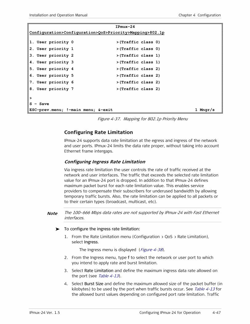
Installation and Operation Manual Chapter 4 Configuration
IPmux-24 Ver. 1.5 Configuring IPmux-24 for Operation 4-47
IPmux-24 Configuration>Configuration>QoS>Priority>Mapping>802.1p
1. User priority 0 >(Traffic class 0)
2. User priority 1 >(Traffic class 0)
3. User priority 2 >(Traffic class 1)
4. User priority 3 >(Traffic class 1)
5. User priority 4 >(Traffic class 2)
6. User priority 5 >(Traffic class 2)
7. User priority 6 >(Traffic class 2)
8. User priority 7 >(Traffic class 2) > S - Save ESC-prev.menu; !-main menu; &-exit 1 Mngr/s
Figure 4-37. Mapping for 802.1p Priority Menu
Configuring Rate Limitation
IPmux-24 supports data rate limitation at the egress and ingress of the network and user ports. IPmux-24 limits the data rate proper, without taking into account Ethernet frame intergaps.
Configuring Ingress Rate Limitation
Via ingress rate limitation the user controls the rate of traffic received at the network and user interfaces. The traffic that exceeds the selected rate limitation value for an IPmux-24 port is dropped. In addition to that IPmux-24 defines maximum packet burst for each rate limitation value. This enables service providers to compensate their subscribers for underused bandwidth by allowing temporary traffic bursts. Also, the rate limitation can be applied to all packets or to their certain types (broadcast, multicast, etc).
The 100–666 Mbps data rates are not supported by IPmux-24 with Fast Ethernet interfaces.
To configure the ingress rate limitation:
1. From the Rate Limitation menu (Configuration > QoS > Rate Limitation), select Ingress.
The Ingress menu is displayed (Figure 4-38).
2. From the Ingress menu, type f to select the network or user port to which you intend to apply rate and burst limitation.
3. Select Rate Limitation and define the maximum ingress data rate allowed on the port (see Table 4-13).
4. Select Burst Size and define the maximum allowed size of the packet buffer (in kilobytes) to be used by the port when traffic bursts occur. See Table 4-13 for the allowed burst values depending on configured port rate limitation. Traffic
Note
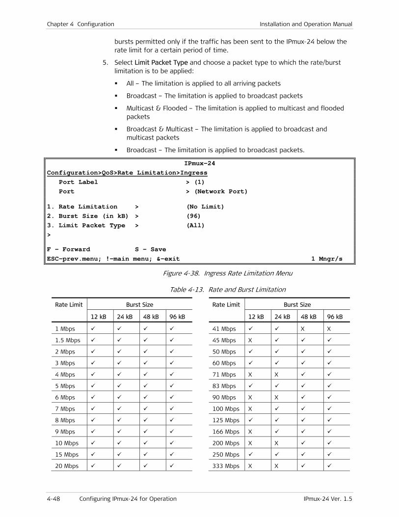
Chapter 4 Configuration Installation and Operation Manual
4-48 Configuring IPmux-24 for Operation IPmux-24 Ver. 1.5
bursts permitted only if the traffic has been sent to the IPmux-24 below the rate limit for a certain period of time.
5. Select Limit Packet Type and choose a packet type to which the rate/burst limitation is to be applied:
All – The limitation is applied to all arriving packets
Broadcast – The limitation is applied to broadcast packets
Multicast & Flooded – The limitation is applied to multicast and flooded packets
Broadcast & Multicast – The limitation is applied to broadcast and multicast packets
Broadcast – The limitation is applied to broadcast packets.
IPmux-24 Configuration>QoS>Rate Limitation>Ingress Port Label > (1) Port > (Network Port)
1. Rate Limitation > (No Limit) 2. Burst Size (in kB) > (96) 3. Limit Packet Type > (All) > F - Forward S – Save ESC-prev.menu; !-main menu; &-exit 1 Mngr/s
Figure 4-38. Ingress Rate Limitation Menu
Table 4-13. Rate and Burst Limitation
Rate Limit Burst Size Rate Limit Burst Size
12 kB 24 kB 48 kB 96 kB 12 kB 24 kB 48 kB 96 kB
1 Mbps 41 Mbps X X
1.5 Mbps 45 Mbps X
2 Mbps 50 Mbps
3 Mbps 60 Mbps
4 Mbps 71 Mbps X X
5 Mbps 83 Mbps
6 Mbps 90 Mbps X X
7 Mbps 100 Mbps X
8 Mbps 125 Mbps
9 Mbps 166 Mbps X
10 Mbps 200 Mbps X X
15 Mbps 250 Mbps
20 Mbps 333 Mbps X X

Installation and Operation Manual Chapter 4 Configuration
IPmux-24 Ver. 1.5 Additional Tasks 4-49
Rate Limit Burst Size Rate Limit Burst Size
12 kB 24 kB 48 kB 96 kB 12 kB 24 kB 48 kB 96 kB
25 Mbps 400 Mbps X
30 Mbps 500 Mbps X
35 Mbps 666 Mbps X
40 Mbps X X
Configuring Egress Rate Limitation
To configure the egress rate limitation:
1. From the QoS menu, select Rate Limitation.
The Rate Limitation menu is displayed.
2. From the Rate Limitation menu, select Egress.
The Egress menu is displayed.
3. From the Ingress menu, type f to select the network or user port to which you intend to apply rate limitation.
4. Select Rate Limitation and define the maximum egress data rate allowed on the port (see Table 4-13).
4.3 Additional Tasks
This section describes additional operations available supported by the IPmux-24 management software, including the following:
• Displaying inventory
• Setting data and time
• Displaying IPmux-24 status
• Transferring software and configuration files
• Resetting the unit.
Displaying the IPmux-24 Inventory
The IPmux-24 inventory displays information on current software and hardware revisions of the unit. It also provides the IPmux-24 interface description.
To display the IPmux-24 inventory:
• From the Main menu, select Inventory.
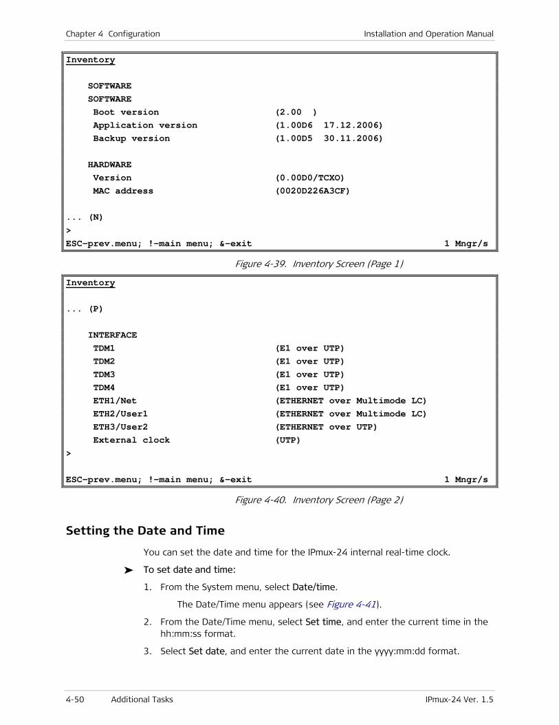
Chapter 4 Configuration Installation and Operation Manual
4-50 Additional Tasks IPmux-24 Ver. 1.5
Inventory SOFTWARE SOFTWARE Boot version (2.00 ) Application version (1.00D6 17.12.2006) Backup version (1.00D5 30.11.2006) HARDWARE Version (0.00D0/TCXO) MAC address (0020D226A3CF) ... (N) > ESC-prev.menu; !-main menu; &-exit 1 Mngr/s
Figure 4-39. Inventory Screen (Page 1)
Inventory ... (P) INTERFACE TDM1 (E1 over UTP) TDM2 (E1 over UTP) TDM3 (E1 over UTP) TDM4 (E1 over UTP) ETH1/Net (ETHERNET over Multimode LC) ETH2/User1 (ETHERNET over Multimode LC) ETH3/User2 (ETHERNET over UTP) External clock (UTP) > ESC-prev.menu; !-main menu; &-exit 1 Mngr/s
Figure 4-40. Inventory Screen (Page 2)
Setting the Date and Time
You can set the date and time for the IPmux-24 internal real-time clock.
To set date and time:
1. From the System menu, select Date/time.
The Date/Time menu appears (see Figure 4-41).
2. From the Date/Time menu, select Set time, and enter the current time in the hh:mm:ss format.
3. Select Set date, and enter the current date in the yyyy:mm:dd format.
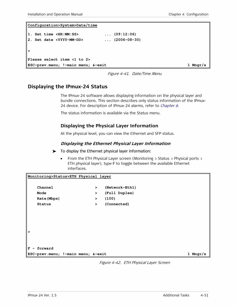
Installation and Operation Manual Chapter 4 Configuration
IPmux-24 Ver. 1.5 Additional Tasks 4-51
Configuration>System>Date/time
1. Set time <HH:MM:SS> ... (09:12:06) 2. Set date <YYYY-MM-DD> ... (2006-08-30) > Please select item <1 to 2> ESC-prev.menu; !-main menu; &-exit 1 Mngr/s
Figure 4-41. Date/Time Menu
Displaying the IPmux-24 Status
The IPmux-24 software allows displaying information on the physical layer and bundle connections. This section describes only status information of the IPmux-24 device. For description of IPmux-24 alarms, refer to Chapter 6.
The status information is available via the Status menu.
Displaying the Physical Layer Information
At the physical level, you can view the Ethernet and SFP status.
Displaying the Ethernet Physical Layer Information
To display the Ethernet physical layer information:
• From the ETH Physical Layer screen (Monitoring > Status > Physical ports > ETH physical layer), type F to toggle between the available Ethernet interfaces.
Monitoring>Status>ETH Physical layer Channel > (Network-Eth1) Mode > (Full Duplex) Rate(Mbps) > (100) Status > (Connected) > F - forward ESC-prev.menu; !-main menu; &-exit 1 Mngr/s
Figure 4-42. ETH Physical Layer Screen
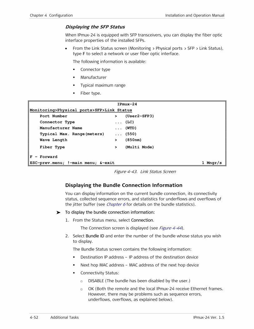
Chapter 4 Configuration Installation and Operation Manual
4-52 Additional Tasks IPmux-24 Ver. 1.5
Displaying the SFP Status
When IPmux-24 is equipped with SFP transceivers, you can display the fiber optic interface properties of the installed SFPs.
• From the Link Status screen (Monitoring > Physical ports > SFP > Link Status), type F to select a network or user fiber optic interface.
The following information is available:
Connector type
Manufacturer
Typical maximum range
Fiber type.
IPmux-24 Monitoring>Physical ports>SFP>Link Status Port Number > (User2-SFP3) Connector Type ... (LC) Manufacturer Name ... (WTD) Typical Max. Range(meters) ... (550) Wave Length > (850nm)
Fiber Type > (Multi Mode)
F - Forward ESC-prev.menu; !-main menu; &-exit 1 Mngr/s
Figure 4-43. Link Status Screen
Displaying the Bundle Connection Information
You can display information on the current bundle connection, its connectivity status, collected sequence errors, and statistics for underflows and overflows of the jitter buffer (see Chapter 6 for details on the bundle statistics).
To display the bundle connection information:
1. From the Status menu, select Connection.
The Connection screen is displayed (see Figure 4-44).
2. Select Bundle ID and enter the number of the bundle whose status you wish to display.
The Bundle Status screen contains the following information:
Destination IP address – IP address of the destination device
Next hop MAC address – MAC address of the next hop device
Connectivity Status:
DISABLE (The bundle has been disabled by the user.)
OK (Both the remote and the local IPmux-24 receive Ethernet frames. However, there may be problems such as sequence errors, underflows, overflows, as explained below).
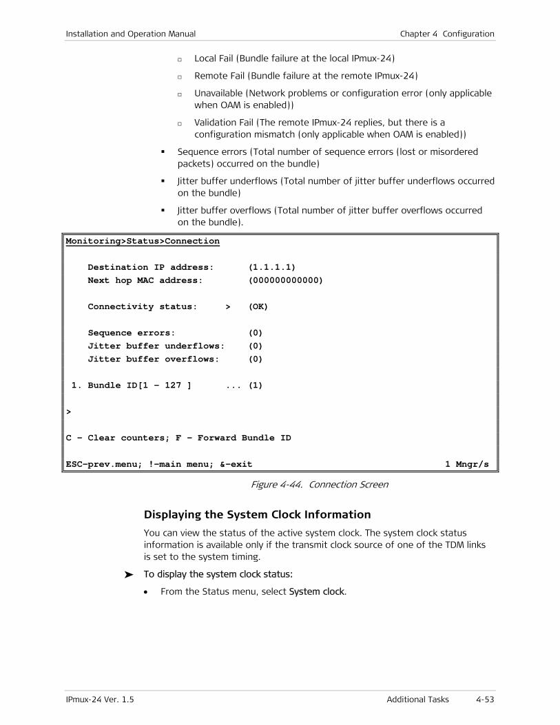
Installation and Operation Manual Chapter 4 Configuration
IPmux-24 Ver. 1.5 Additional Tasks 4-53
Local Fail (Bundle failure at the local IPmux-24)
Remote Fail (Bundle failure at the remote IPmux-24)
Unavailable (Network problems or configuration error (only applicable when OAM is enabled))
Validation Fail (The remote IPmux-24 replies, but there is a configuration mismatch (only applicable when OAM is enabled))
Sequence errors (Total number of sequence errors (lost or misordered packets) occurred on the bundle)
Jitter buffer underflows (Total number of jitter buffer underflows occurred on the bundle)
Jitter buffer overflows (Total number of jitter buffer overflows occurred on the bundle).
Monitoring>Status>Connection Destination IP address: (1.1.1.1) Next hop MAC address: (000000000000) Connectivity status: > (OK) Sequence errors: (0) Jitter buffer underflows: (0) Jitter buffer overflows: (0) 1. Bundle ID[1 – 127 ] ... (1) > C - Clear counters; F - Forward Bundle ID ESC-prev.menu; !-main menu; &-exit 1 Mngr/s
Figure 4-44. Connection Screen
Displaying the System Clock Information
You can view the status of the active system clock. The system clock status information is available only if the transmit clock source of one of the TDM links is set to the system timing.
To display the system clock status:
• From the Status menu, select System clock.
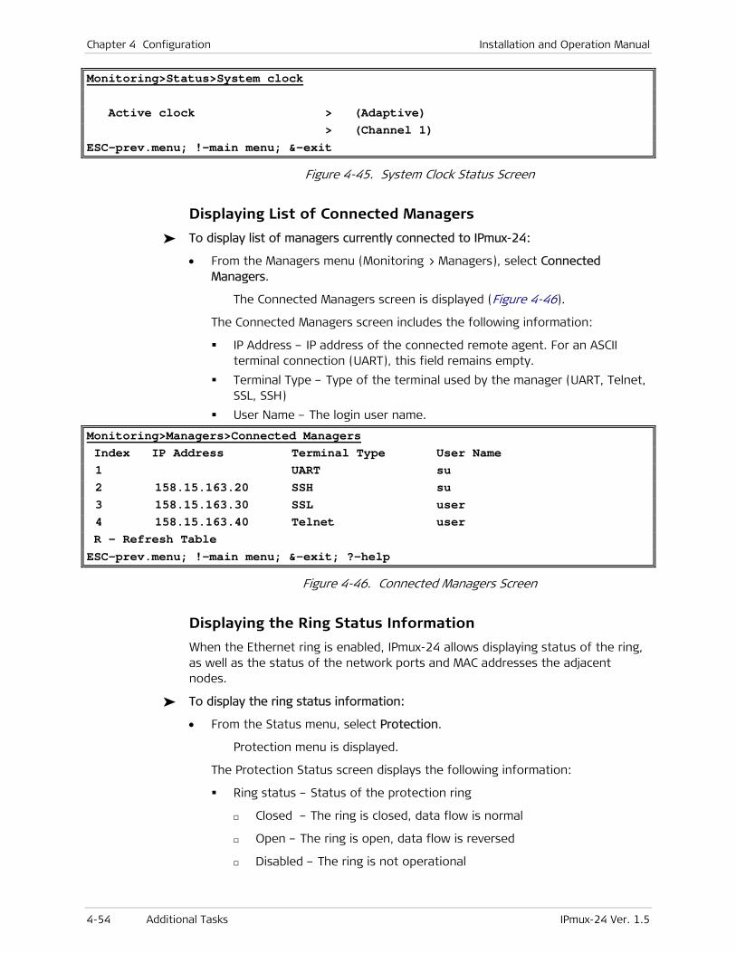
Chapter 4 Configuration Installation and Operation Manual
4-54 Additional Tasks IPmux-24 Ver. 1.5
Monitoring>Status>System clock Active clock > (Adaptive) > (Channel 1) ESC-prev.menu; !-main menu; &-exit
Figure 4-45. System Clock Status Screen
Displaying List of Connected Managers
To display list of managers currently connected to IPmux-24:
• From the Managers menu (Monitoring > Managers), select Connected Managers.
The Connected Managers screen is displayed (Figure 4-46).
The Connected Managers screen includes the following information:
IP Address – IP address of the connected remote agent. For an ASCII terminal connection (UART), this field remains empty.
Terminal Type – Type of the terminal used by the manager (UART, Telnet, SSL, SSH)
User Name – The login user name.
Monitoring>Managers>Connected Managers Index IP Address Terminal Type User Name 1 UART su 2 158.15.163.20 SSH su 3 158.15.163.30 SSL user 4 158.15.163.40 Telnet user R - Refresh Table ESC-prev.menu; !-main menu; &-exit; ?-help
Figure 4-46. Connected Managers Screen
Displaying the Ring Status Information
When the Ethernet ring is enabled, IPmux-24 allows displaying status of the ring, as well as the status of the network ports and MAC addresses the adjacent nodes.
To display the ring status information:
• From the Status menu, select Protection.
Protection menu is displayed.
The Protection Status screen displays the following information:
Ring status – Status of the protection ring
Closed – The ring is closed, data flow is normal
Open – The ring is open, data flow is reversed
Disabled – The ring is not operational

Installation and Operation Manual Chapter 4 Configuration
IPmux-24 Ver. 1.5 Additional Tasks 4-55
Port Status – Status of the IPmux-24 network port in the ring application:
Blocking – The port operates as a blocking node, transferring the ring status messages only
Up – The port is operational
Down – The port ins not operational
Monitoring>Status>Protection
Ring Status > (CLOSED)
Port 1 Status > (UP)
Port 2 Status > (Down)
ESC-prev.menu; !-main menu; &-exit 1 M/ 1 C
Figure 4-47. Protection Status Screen
Transferring Software and Configuration Files
Software and configuration files can be transferred using TFTP.
To transfer a file using TFTP:
1. From the Utilities menu, select File Utilities.
2. From the File Utilities, select Download/Upload using TFTP.
3. From the Download/Upload using TFTP menu, configure the following:
File name (Name of the file that you intend to transfer)
Command (Operation type)
No operation
Software download
Software upload
Configuration download
Configuration upload
Software download and reset
Server IP (IP address of the TFTP server)
Retry Timeout (Interval between connection retries in seconds).
Total Timeout (TFTP connection timeout in seconds)
View Transfer Status (Current status of the TFTP transfer)
4. Save the changes.
IPmux-24 starts file transfer using TFTP.

Chapter 4 Configuration Installation and Operation Manual
4-56 Additional Tasks IPmux-24 Ver. 1.5
Utilities>File Utilities>Download/upload using TFTP
1. File name ... (FILE.IMG) 2. Command > (No operation) 3. Server IP ... (0.0.0.0) 4. Retry timeout(sec)[0 - 1000] ... (1) 5. Total timeout(sec)[0 - 1000] ... (5) 6. View transfer status > > ESC-prev.menu; !-main menu; &-exit 1 Mngr/s
Figure 4-48. Download/Upload Using TFTP Menu
Resetting IPmux-24
IPmux-24 supports two types of reset:
• Reset to the default setting
Resetting all parameters
Resetting all parameters, except for management values
• Overall reset of the device.
Resetting IPmux-24 to the Defaults
You can reset IPmux-24 to its default settings. The reset to the defaults does not affect the master clock setting. In addition, you can reset local IPmux-24 without affecting its management parameters (host IP address, mask and default gateway, defined network managers and management access methods).
To reset IPmux-24 to the default settings:
1. From the System menu, select Factory default.
2. From the Factory Default menu, perform one the following steps:
Select All to reset all IPmux-24 parameters to the default settings.
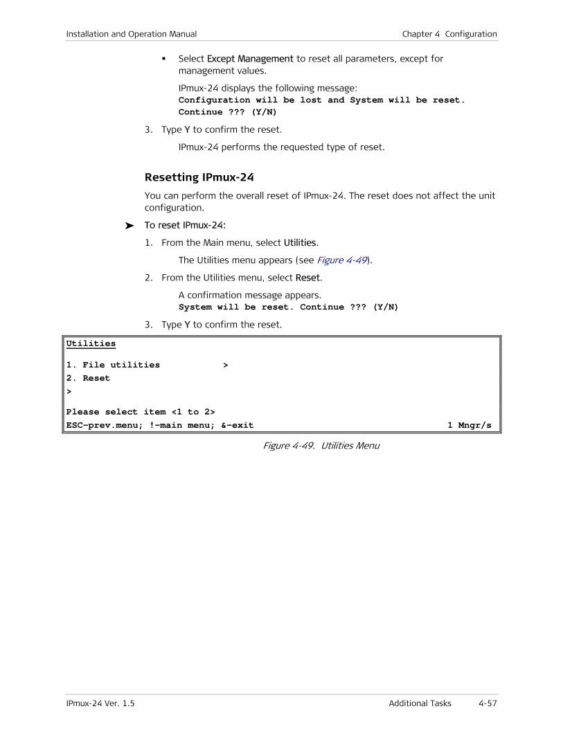
Installation and Operation Manual Chapter 4 Configuration
IPmux-24 Ver. 1.5 Additional Tasks 4-57
Select Except Management to reset all parameters, except for management values.
IPmux-24 displays the following message: Configuration will be lost and System will be reset. Continue ??? (Y/N)
3. Type Y to confirm the reset.
IPmux-24 performs the requested type of reset.
Resetting IPmux-24
You can perform the overall reset of IPmux-24. The reset does not affect the unit configuration.
To reset IPmux-24:
1. From the Main menu, select Utilities.
The Utilities menu appears (see Figure 4-49).
2. From the Utilities menu, select Reset.
A confirmation message appears. System will be reset. Continue ??? (Y/N)
3. Type Y to confirm the reset.
Utilities
1. File utilities > 2. Reset > Please select item <1 to 2> ESC-prev.menu; !-main menu; &-exit 1 Mngr/s
Figure 4-49. Utilities Menu

Chapter 4 Configuration Installation and Operation Manual
4-58 Additional Tasks IPmux-24 Ver. 1.5
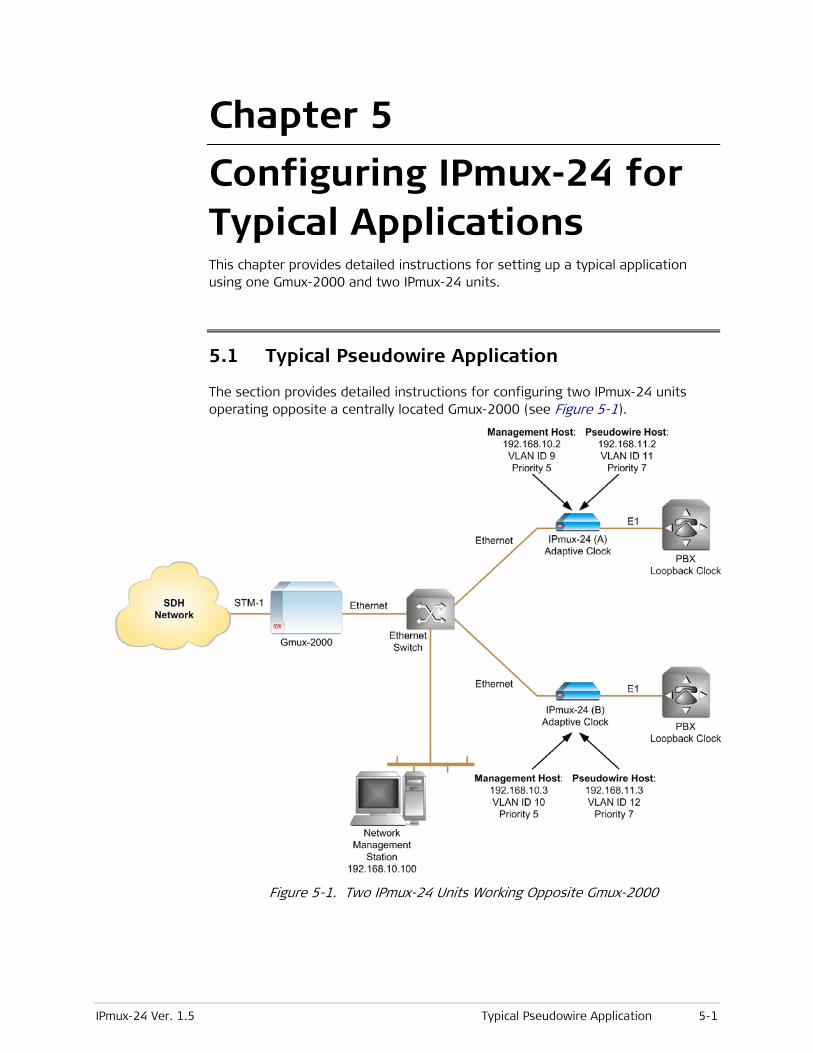
IPmux-24 Ver. 1.5 Typical Pseudowire Application 5-1
Chapter 5
Configuring IPmux-24 for Typical Applications This chapter provides detailed instructions for setting up a typical application using one Gmux-2000 and two IPmux-24 units.
5.1 Typical Pseudowire Application
The section provides detailed instructions for configuring two IPmux-24 units operating opposite a centrally located Gmux-2000 (see Figure 5-1).
Figure 5-1. Two IPmux-24 Units Working Opposite Gmux-2000

Chapter 5 Configuring IPmux-24 for Typical Applications Installation and Operation Manual
5-2 Typical Pseudowire Application IPmux-24 Ver. 1.5
Configuration Sequence
Below are the basic configuration steps that need to be followed when deploying an IPmux-24 unit in a typical pseudowire application.
1. Configuring the management host
2. Setting the TDM physical layer parameters (line type, clocking, etc.) according to the application requirements and topology.
3. Configuring a pseudowire host.
4. Allocating timeslots to bundles
5. Connecting bundles to a remote pseudowire device.
Table 5-1. Configuration Summary
Device E1 Parameters Management
Host Parameters
PW Host Parameters Bundle Parameters
IPmux-24 (A) Transmit clock source:
Adaptive
Line type: Framed G.704
CRC-4 enabled
CAS disabled
IP address:
192.168.10.2
VLAN ID: 9
VLAN priority: 5
IP address: 192.168.11.2
VLAN ID: 11
VLAN priority: 7
Bundle 1: TS 1–10
Bundle 2: TS 11–15
Bundle 3: TS 16–20
Bundle 4: TS 21–30
IPmux-24 (B) Transmit clock source:
Adaptive
Line type: Framed G.704
CRC-4 enabled
CAS disabled
IP address:
192.168.10.3
VLAN ID: 10
VLAN priority: 5
IP address: 192.168.11.3
VLAN ID: 12
VLAN priority: 7
Bundle 1: TS 1–10
Bundle 2: TS 11–15
Bundle 3: TS 16–20
Bundle 4: TS 21–30
Configuring the IPmux-24 Units
This section explains how to configure the IPmux-24 units. Refer to Chapter 3 for explanation of how to select management options and save the changes.
Configuring the Management Host
To establish a proper connection between the IPmux-24 units and an NMS, perform the following:
• Define the IPmux-24 management hosts
• Enable host tagging and configure the VLAN parameters to separate the management traffic from the pseudowire traffic
• Add the NMS to the manager lists of the units.
To configure the management host IP parameters:
• Display the Host IP menu (Configuration > System > Management > Host IP), and configure the IP address and mask of the host:
1. Disable the DHCP mechanism
2. Save the changes
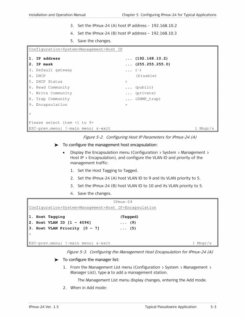
Installation and Operation Manual Chapter 5 Configuring IPmux-24 for Typical Applications
IPmux-24 Ver. 1.5 Typical Pseudowire Application 5-3
3. Set the IPmux-24 (A) host IP address – 192.168.10.2
4. Set the IPmux-24 (B) host IP address – 192.168.10.3
5. Save the changes.
Configuration>System>Management>Host IP
1. IP address ... (192.168.10.2) 2. IP mask ... (255.255.255.0) 3. Default gateway ... (–) 4. DHCP (Disable) 5. DHCP Status > 6. Read Community ... (public) 7. Write Community ... (private) 8. Trap Community ... (SNMP_trap) 9. Encapsulation > > Please select item <1 to 9>
ESC-prev.menu; !-main menu; &-exit 1 Mngr/s
Figure 5-2. Configuring Host IP Parameters for IPmux-24 (A)
To configure the management host encapsulation:
• Display the Encapsulation menu (Configuration > System > Management > Host IP > Encapsulation), and configure the VLAN ID and priority of the management traffic:
1. Set the Host Tagging to Tagged.
2. Set the IPmux-24 (A) host VLAN ID to 9 and its VLAN priority to 5.
3. Set the IPmux-24 (B) host VLAN ID to 10 and its VLAN priority to 5.
4. Save the changes.
IPmux-24 Configuration>System>Management>Host IP>Encapsulation
1. Host Tagging (Tagged) 2. Host VLAN ID [1 - 4094] ... (9) 3. Host VLAN Priority [0 - 7] ... (5) > ESC-prev.menu; !-main menu; &-exit 1 Mngr/s
Figure 5-3. Configuring the Management Host Encapsulation for IPmux-24 (A)
To configure the manager list:
1. From the Management List menu (Configuration > System > Management > Manager List), type a to add a management station.
The Management List menu display changes, entering the Add mode.
2. When in Add mode:
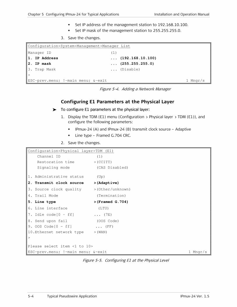
Chapter 5 Configuring IPmux-24 for Typical Applications Installation and Operation Manual
5-4 Typical Pseudowire Application IPmux-24 Ver. 1.5
Set IP address of the management station to 192.168.10.100.
Set IP mask of the management station to 255.255.255.0.
3. Save the changes.
Configuration>System>Management>Manager List
Manager ID (1) 1. IP Address ... (192.168.10.100) 2. IP mask ... (255.255.255.0) 3. Trap Mask ... (Disable) >
ESC-prev.menu; !-main menu; &-exit 1 Mngr/s
Figure 5-4. Adding a Network Manager
Configuring E1 Parameters at the Physical Layer
To configure E1 parameters at the physical layer:
1. Display the TDM (E1) menu (Configuration > Physical layer > TDM (E1)), and configure the following parameters:
IPmux-24 (A) and IPmux-24 (B) transmit clock source – Adaptive
Line type – Framed G.704 CRC.
2. Save the changes.
Configuration>Physical layer>TDM (E1) Channel ID (1) Restoration time >(CCITT) Signaling mode (CAS Disabled)
1. Administrative status (Up)
2. Transmit clock source >(Adaptive)
3. Source clock quality >(Other/unknown)
4. Trail Mode (Termination)
5. Line type >(Framed G.704)
6. Line interface (LTU) 7. Idle code[0 - ff] ... (7E)
8. Send upon fail (OOS Code) 9. OOS Code[0 - ff] ... (FF) 10.Ethernet network type >(WAN) > Please select item <1 to 10>
ESC-prev.menu; !-main menu; &-exit 1 Mngr/s
Figure 5-5. Configuring E1 at the Physical Level
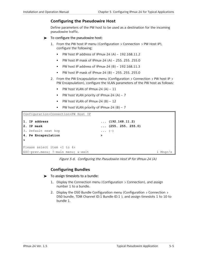
Installation and Operation Manual Chapter 5 Configuring IPmux-24 for Typical Applications
IPmux-24 Ver. 1.5 Typical Pseudowire Application 5-5
Configuring the Pseudowire Host
Define parameters of the PW host to be used as a destination for the incoming pseudowire traffic.
To configure the pseudowire host:
1. From the PW host IP menu (Configuration > Connection > PW Host IP), configure the following:
PW host IP address of IPmux-24 (A) – 192.168.11.2
PW host IP mask of IPmux-24 (A) – 255. 255. 255.0
PW host IP address of IPmux-24 (B) – 192.168.11.3
PW host IP mask of IPmux-24 (B) – 255. 255. 255.0
2. From the PW Encapsulation menu (Configuration > Connection > PW host IP > PW Encapsulation), configure the VLAN parameters of the PW host as follows:
PW host VLAN of IPmux-24 (A) – 11
PW host VLAN priority of IPmux-24 (A) – 7
PW host VLAN of IPmux-24 (B) – 12
PW host VLAN priority of IPmux-24 (B) – 7
Configuration>Connection>PW Host IP
1. IP address ... (192.168.11.2) 2. IP mask ... (255. 255. 255.0) 3. Default next hop ... (-) 4. Pw Encapsulation > > Please select item <1 to 4>
ESC-prev.menu; !-main menu; &-exit 1 Mngr/s
Figure 5-6. Configuring the Pseudowire Host IP for IPmux-24 (A)
Configuring Bundles
To assign timeslots to a bundle:
1. Display the Connection menu (Configuration > Connection), and assign number 1 to a bundle.
2. Display the DS0 Bundle Configuration menu (Configuration > Connection > DS0 bundle, TDM Channel ID:1 Bundle ID:1 ), and assign timeslots 1 to 10 to bundle 1.
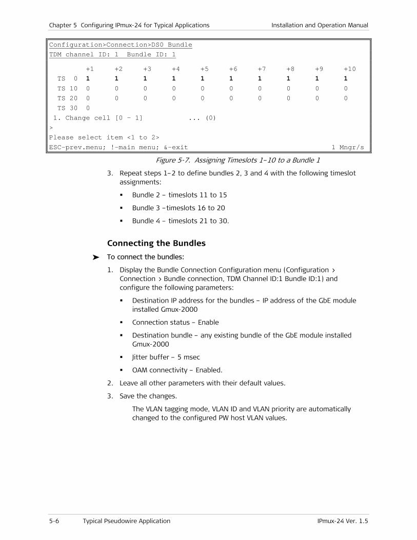
Chapter 5 Configuring IPmux-24 for Typical Applications Installation and Operation Manual
5-6 Typical Pseudowire Application IPmux-24 Ver. 1.5
Configuration>Connection>DS0 Bundle TDM channel ID: 1 Bundle ID: 1 +1 +2 +3 +4 +5 +6 +7 +8 +9 +10 TS 0 1 1 1 1 1 1 1 1 1 1 TS 10 0 0 0 0 0 0 0 0 0 0 TS 20 0 0 0 0 0 0 0 0 0 0 TS 30 0 1. Change cell [0 - 1] ... (0) > Please select item <1 to 2>
ESC-prev.menu; !-main menu; &-exit 1 Mngr/s
Figure 5-7. Assigning Timeslots 1–10 to a Bundle 1
3. Repeat steps 1–2 to define bundles 2, 3 and 4 with the following timeslot assignments:
Bundle 2 – timeslots 11 to 15
Bundle 3 –timeslots 16 to 20
Bundle 4 – timeslots 21 to 30.
Connecting the Bundles
To connect the bundles:
1. Display the Bundle Connection Configuration menu (Configuration > Connection > Bundle connection, TDM Channel ID:1 Bundle ID:1) and configure the following parameters:
Destination IP address for the bundles – IP address of the GbE module installed Gmux-2000
Connection status – Enable
Destination bundle – any existing bundle of the GbE module installed Gmux-2000
Jitter buffer – 5 msec
OAM connectivity – Enabled.
2. Leave all other parameters with their default values.
3. Save the changes.
The VLAN tagging mode, VLAN ID and VLAN priority are automatically changed to the configured PW host VLAN values.
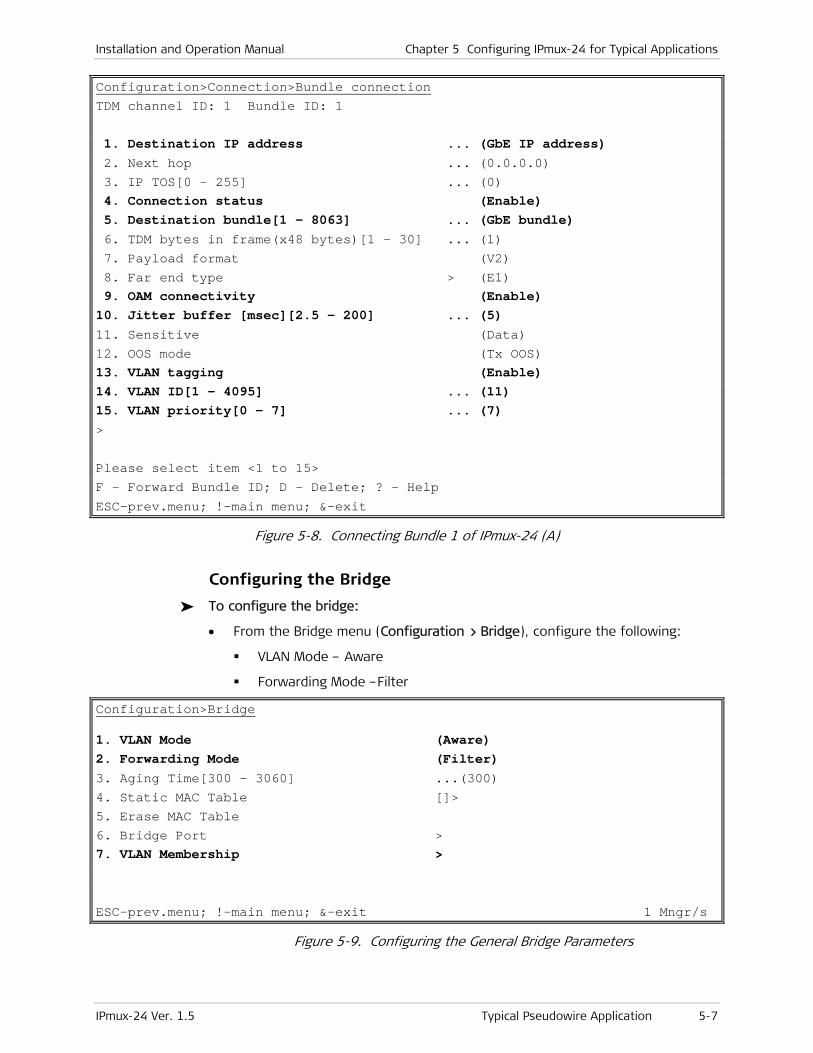
Installation and Operation Manual Chapter 5 Configuring IPmux-24 for Typical Applications
IPmux-24 Ver. 1.5 Typical Pseudowire Application 5-7
Configuration>Connection>Bundle connection TDM channel ID: 1 Bundle ID: 1 1. Destination IP address ... (GbE IP address) 2. Next hop ... (0.0.0.0) 3. IP TOS[0 - 255] ... (0) 4. Connection status (Enable) 5. Destination bundle[1 - 8063] ... (GbE bundle) 6. TDM bytes in frame(x48 bytes)[1 - 30] ... (1) 7. Payload format (V2) 8. Far end type > (E1) 9. OAM connectivity (Enable) 10. Jitter buffer [msec][2.5 - 200] ... (5) 11. Sensitive (Data) 12. OOS mode (Tx OOS) 13. VLAN tagging (Enable) 14. VLAN ID[1 - 4095] ... (11) 15. VLAN priority[0 - 7] ... (7) > Please select item <1 to 15> F - Forward Bundle ID; D - Delete; ? - Help
ESC-prev.menu; !-main menu; &-exit
Figure 5-8. Connecting Bundle 1 of IPmux-24 (A)
Configuring the Bridge
To configure the bridge:
• From the Bridge menu (Configuration > Bridge), configure the following:
VLAN Mode – Aware
Forwarding Mode –Filter
Configuration>Bridge
1. VLAN Mode (Aware) 2. Forwarding Mode (Filter) 3. Aging Time[300 - 3060] ...(300) 4. Static MAC Table []> 5. Erase MAC Table 6. Bridge Port > 7. VLAN Membership >
ESC-prev.menu; !-main menu; &-exit 1 Mngr/s
Figure 5-9. Configuring the General Bridge Parameters

Chapter 5 Configuring IPmux-24 for Typical Applications Installation and Operation Manual
5-8 Typical Pseudowire Application with Ring Protection IPmux-24 Ver. 1.5
Configuring the VLAN Membership
To configure the VLAN Membership:
• From the VLAN Membership menu (Configuration > Bridge > VLAN Membership), set the IPmux-24 network port to be a tagged member of VLAN 11 (IPmux-24 A) or VLAN 12 (IPmux-24 B):
1. Type a to invoke the Add mode.
2. In the Add mode, set VLAN ID to 11 (IPmux-24 A) or VLAN 12 (IPmux-24 B).
3. Save the changes.
4. Select Egress Tagged Ports and type a to invoke the Add mode.
5. In the Add mode, set Egress Tagged Port to 1.
Configuration>Bridge>Vlan Membership
Vlan Id[1 - 4094] ... (11) 1. Egress Tagged Ports > (1) 2. Egress Untagged Ports > (–) > Please select item <1 to 2> A - Add New VLAN ; F - Forward ; D - Delete
ESC-prev.menu; !-main menu; &-exit 1 Mngr/s
Figure 5-10. Configuring Network Port as VLAN 11 Members (IPmux-24 A)
5.2 Typical Pseudowire Application with Ring Protection
The section provides detailed instructions for configuring four IPmux-24 units in a ring topology operating opposite a centrally located Gmux-2000 (see Figure 5-11). Each IPmux-24 transfers PW data to Gmux-2000 over two bundles. Data flow between the IPmux-24 devices is protected by the VLAN-based resilient Ethernet ring.
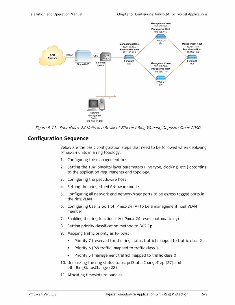
Installation and Operation Manual Chapter 5 Configuring IPmux-24 for Typical Applications
IPmux-24 Ver. 1.5 Typical Pseudowire Application with Ring Protection 5-9
Figure 5-11. Four IPmux-24 Units in a Resilient Ethernet Ring Working Opposite Gmux-2000
Configuration Sequence
Below are the basic configuration steps that need to be followed when deploying IPmux-24 units in a ring topology.
1. Configuring the management host
2. Setting the TDM physical layer parameters (line type, clocking, etc.) according to the application requirements and topology.
3. Configuring the pseudowire host
4. Setting the bridge to VLAN-aware mode
5. Configuring all network and network/user ports to be egress tagged ports in the ring VLAN
6. Configuring User 2 port of IPmux-24 (A) to be a management host VLAN member
7. Enabling the ring functionality (IPmux-24 resets automatically)
8. Setting priority classification method to 802.1p
9. Mapping traffic priority as follows:
Priority 7 (reserved for the ring status traffic) mapped to traffic class 2
Priority 6 (PW traffic) mapped to traffic class 1
Priority 5 (management traffic) mapped to traffic class 0
10. Unmasking the ring status traps: prtStatusChangeTrap (27) and ethIfRingStatusChange (28)
11. Allocating timeslots to bundles

Chapter 5 Configuring IPmux-24 for Typical Applications Installation and Operation Manual
5-10 Typical Pseudowire Application with Ring Protection IPmux-24 Ver. 1.5
12. Connecting bundles to the central Gmux-2000
Table 5-2. Configuration Summary
Device E1 Parameters Management
Host
Parameters
PW Host
Parameters
Bundle Parameters Ring Traffic
IPmux-24 (A) Transmit clock source:
Adaptive
Line type: Framed
G.704 CRC-4 enabled
CAS disabled
IP address:
192.168.10.2
VLAN ID: 9
VLAN priority: 5
IP address:
192.168.11.2
VLAN ID: 11
VLAN priority: 6
Bundle 1: TS 1–10
Bundle 2: TS 11–15
VLAN ID: 100
VLAN priority: 7
IPmux-24 (B) Transmit clock source:
Adaptive
Line type: Framed
G.704 CRC-4 enabled
CAS disabled
IP address:
192.168.10.3
VLAN ID: 9
VLAN priority: 5
IP address:
192.168.11.3
VLAN ID: 11
VLAN priority: 6
Bundle 1: TS 1–10
Bundle 2: TS 11–15
VLAN ID: 100
VLAN priority: 7
IPmux-24 (C) Transmit clock source:
Adaptive
Line type: Framed
G.704 CRC-4 enabled
CAS disabled
IP address:
192.168.10.4
VLAN ID: 9
VLAN priority: 5
IP address:
192.168.11.4
VLAN ID: 11
VLAN priority: 6
Bundle 1: TS 1–10
Bundle 2: TS 11–15
VLAN ID: 100
VLAN priority: 7
IPmux-24 (C) Transmit clock source:
Adaptive
Line type: Framed
G.704 CRC-4 enabled
CAS disabled
IP address:
192.168.10.5
VLAN ID: 9
VLAN priority: 5
IP address:
192.168.11.5
VLAN ID: 11
VLAN priority: 6
Bundle 1: TS 1–10
Bundle 2: TS 11–15
VLAN ID: 100
VLAN priority: 7
Configuring the Management Host
Refer to the Configuring the Management Host section above for instruction on how to configure the management host parameters of the IPmux-24 units.
Setting the TDM Physical Layer Parameters
Refer to the Configuring E1 Parameters at the Physical Layer section above for instruction on how to configure physical layer of the E1 interfaces.
Configuring the Pseudowire Host
Refer to the Configuring the Pseudowire Host section above for instruction on how to define the pseudowire host for PW traffic.
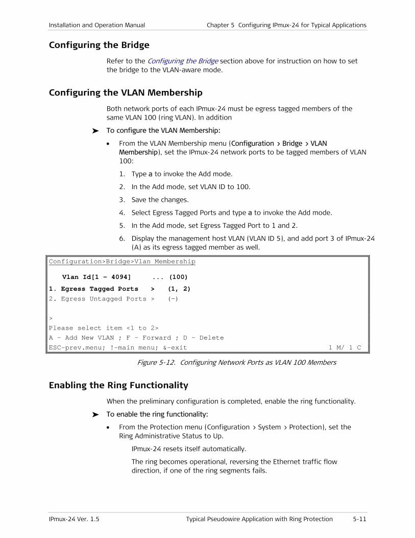
Installation and Operation Manual Chapter 5 Configuring IPmux-24 for Typical Applications
IPmux-24 Ver. 1.5 Typical Pseudowire Application with Ring Protection 5-11
Configuring the Bridge
Refer to the Configuring the Bridge section above for instruction on how to set the bridge to the VLAN-aware mode.
Configuring the VLAN Membership
Both network ports of each IPmux-24 must be egress tagged members of the same VLAN 100 (ring VLAN). In addition
To configure the VLAN Membership:
• From the VLAN Membership menu (Configuration > Bridge > VLAN Membership), set the IPmux-24 network ports to be tagged members of VLAN 100:
1. Type a to invoke the Add mode.
2. In the Add mode, set VLAN ID to 100.
3. Save the changes.
4. Select Egress Tagged Ports and type a to invoke the Add mode.
5. In the Add mode, set Egress Tagged Port to 1 and 2.
6. Display the management host VLAN (VLAN ID 5), and add port 3 of IPmux-24 (A) as its egress tagged member as well.
Configuration>Bridge>Vlan Membership
Vlan Id[1 - 4094] ... (100)
1. Egress Tagged Ports > (1, 2) 2. Egress Untagged Ports > (–) > Please select item <1 to 2> A - Add New VLAN ; F - Forward ; D - Delete
ESC-prev.menu; !-main menu; &-exit 1 M/ 1 C
Figure 5-12. Configuring Network Ports as VLAN 100 Members
Enabling the Ring Functionality
When the preliminary configuration is completed, enable the ring functionality.
To enable the ring functionality:
• From the Protection menu (Configuration > System > Protection), set the Ring Administrative Status to Up.
IPmux-24 resets itself automatically.
The ring becomes operational, reversing the Ethernet traffic flow direction, if one of the ring segments fails.
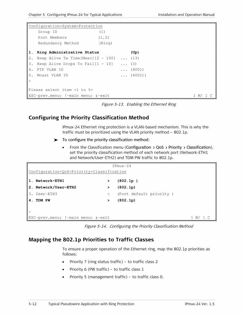
Chapter 5 Configuring IPmux-24 for Typical Applications Installation and Operation Manual
5-12 Typical Pseudowire Application with Ring Protection IPmux-24 Ver. 1.5
Configuration>System>Protection Group ID (1) Port Members (1,2) Redundancy Method (Ring)
1. Ring Administrative Status (Up) 2. Keep Alive Tx Time[Msec][2 - 100] ... (13) 3. Keep Alive Drops To Fall[1 - 10] ... (3) 4. PTP VLAN ID ... (4001) 5. Mcast VLAN ID ... (4002)) > Please select item <1 to 5>
ESC-prev.menu; !-main menu; &-exit 1 M/ 1 C
Figure 5-13. Enabling the Ethernet Ring
Configuring the Priority Classification Method
IPmux-24 Ethernet ring protection is a VLAN-based mechanism. This is why the traffic must be prioritized using the VLAN priority method – 802.1p.
To configure the priority classification method:
• From the Classification menu (Configuration > QoS > Priority > Classification), set the priority classification method of each network port (Network-ETH1 and Network/User-ETH2) and TDM PW traffic to 802.1p.
IPmux-24 Configuration>QoS>Priority>Classification
1. Network-ETH1 > (802.1p ) 2. Network/User-ETH2 > (802.1p) 3. User-ETH3 > (Port default priority ) 4. TDM PW > (802.1p) >
ESC-prev.menu; !-main menu; &-exit 1 M/ 1 C
Figure 5-14. Configuring the Priority Classification Method
Mapping the 802.1p Priorities to Traffic Classes
To ensure a proper operation of the Ethernet ring, map the 802.1p priorities as follows:
• Priority 7 (ring status traffic) – to traffic class 2
• Priority 6 (PW traffic) – to traffic class 1
• Priority 5 (management traffic) – to traffic class 0.
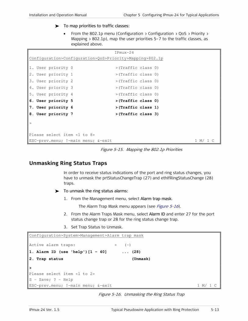
Installation and Operation Manual Chapter 5 Configuring IPmux-24 for Typical Applications
IPmux-24 Ver. 1.5 Typical Pseudowire Application with Ring Protection 5-13
To map priorities to traffic classes:
• From the 802.1p menu (Configuration > Configuration > QoS > Priority > Mapping > 802.1p), map the user priorities 5–7 to the traffic classes, as explained above.
IPmux-24 Configuration>Configuration>QoS>Priority>Mapping>802.1p
1. User priority 0 >(Traffic class 0)
2. User priority 1 >(Traffic class 0)
3. User priority 2 >(Traffic class 0)
4. User priority 3 >(Traffic class 0)
5. User priority 4 >(Traffic class 0)
6. User priority 5 >(Traffic class 0)
7. User priority 6 >(Traffic class 1)
8. User priority 7 >(Traffic class 3) > Please select item <1 to 8> ESC-prev.menu; !-main menu; &-exit 1 M/ 1 C
Figure 5-15. Mapping the 802.1p Priorities
Unmasking Ring Status Traps
In order to receive status indications of the port and ring status changes, you have to unmask the prtStatusChangeTrap (27) and ethIfRingStatusChange (28) traps.
To unmask the ring status alarms:
1. From the Management menu, select Alarm trap mask.
The Alarm Trap Mask menu appears (see Figure 5-16).
2. From the Alarm Traps Mask menu, select Alarm ID and enter 27 for the port status change trap or 28 for the ring status change trap.
3. Set Trap Status to Unmask.
Configuration>System>Management>Alarm trap mask
Active alarm traps: > (-)
1. Alarm ID (use 'help')[1 - 40] ... (28) 2. Trap status (Unmask) > Please select item <1 to 2> S - Save; ? - Help ESC-prev.menu; !-main menu; &-exit 1 M/ 1 C
Figure 5-16. Unmasking the Ring Status Trap
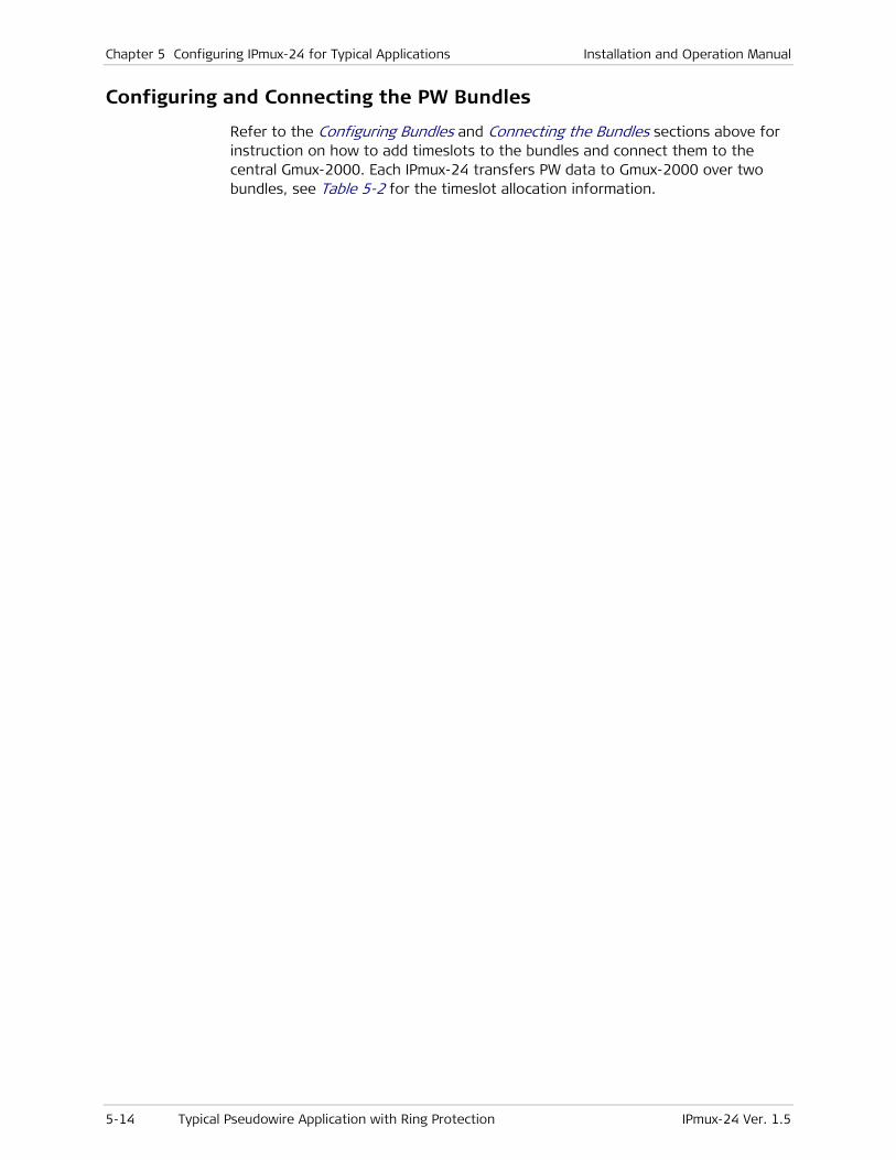
Chapter 5 Configuring IPmux-24 for Typical Applications Installation and Operation Manual
5-14 Typical Pseudowire Application with Ring Protection IPmux-24 Ver. 1.5
Configuring and Connecting the PW Bundles
Refer to the Configuring Bundles and Connecting the Bundles sections above for instruction on how to add timeslots to the bundles and connect them to the central Gmux-2000. Each IPmux-24 transfers PW data to Gmux-2000 over two bundles, see Table 5-2 for the timeslot allocation information.
IPmux-24 Ver. 1.5 Monitoring Performance 6-1
Chapter 6
Diagnostics and Troubleshooting This chapter describes how to:
• Monitor performance
• Detect errors
• Handle alarms
• Troubleshoot problems
• Perform diagnostic tests.
6.1 Monitoring Performance
IPmux-24 provides powerful performance monitoring tools, which consist of the following three levels:
• E1/T1 statistics – Status of the physical E1/T1 parameters (signal, framing, etc.)
• Ethernet statistics – Ethernet connection status (speed, duplex mode, bytes transmitted & received, etc.)
• Bundle connection statistics – TDMoIP bundle connection status on the Ethernet/IP network level.
Displaying E1/T1 Statistics
E1/T1 statistics refer to the physical status of the E1/T1 traffic reaching IPmux-24 from the adjacent E1/T1 device.
The E1 statistics parameters comply with the G.703, G.704, G.804, G.706, G.732, and G.823 standards.
The T1 statistics parameters comply with the ANSI T.403, AT&T R62411, G.703, G.704 and G.804 standards.
E1/T1 statistics are monitored and saved under consecutive intervals. Each interval is 15 minutes long. There are 96 intervals, which represent the last 24 hours. Whenever a new interval is started, the counters are reset to zero. The old interval shows the total of events that occurred during its 15-minite period. The current active interval is always marked as interval 0 (you will see that the Time Since counter is running). The previous interval is marked as 1 and so on. The E1/T1 statistic counters cannot be reset manually.
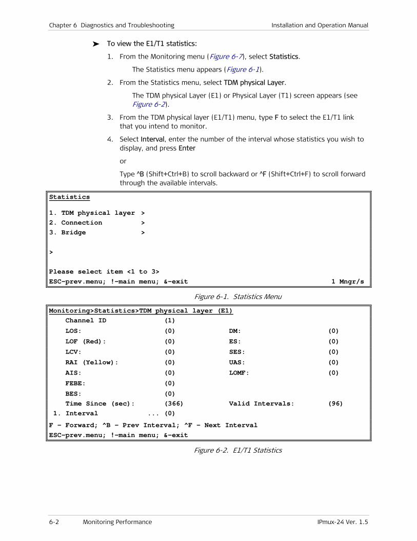
Chapter 6 Diagnostics and Troubleshooting Installation and Operation Manual
6-2 Monitoring Performance IPmux-24 Ver. 1.5
To view the E1/T1 statistics:
1. From the Monitoring menu (Figure 6-7), select Statistics.
The Statistics menu appears (Figure 6-1).
2. From the Statistics menu, select TDM physical Layer.
The TDM physical Layer (E1) or Physical Layer (T1) screen appears (see Figure 6-2).
3. From the TDM physical layer (E1/T1) menu, type F to select the E1/T1 link that you intend to monitor.
4. Select Interval, enter the number of the interval whose statistics you wish to display, and press Enter
or
Type ^B (Shift+Ctrl+B) to scroll backward or ^F (Shift+Ctrl+F) to scroll forward through the available intervals.
Statistics
1. TDM physical layer > 2. Connection > 3. Bridge > > Please select item <1 to 3> ESC-prev.menu; !-main menu; &-exit 1 Mngr/s
Figure 6-1. Statistics Menu
Monitoring>Statistics>TDM physical layer (E1) Channel ID (1)
LOS: (0) DM: (0)
LOF (Red): (0) ES: (0)
LCV: (0) SES: (0)
RAI (Yellow): (0) UAS: (0)
AIS: (0) LOMF: (0)
FEBE: (0)
BES: (0) Time Since (sec): (366) Valid Intervals: (96) 1. Interval ... (0)
F - Forward; ^B - Prev Interval; ^F - Next Interval ESC-prev.menu; !-main menu; &-exit
Figure 6-2. E1/T1 Statistics
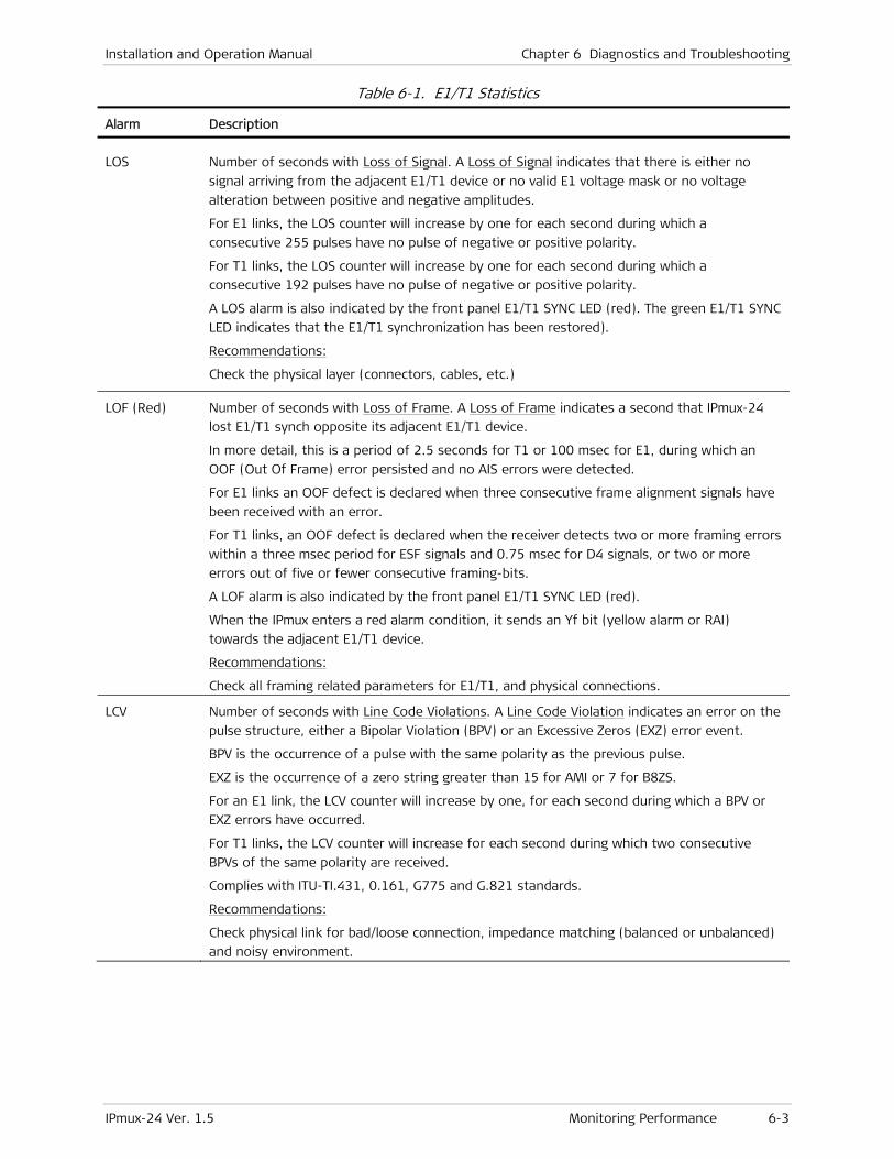
Installation and Operation Manual Chapter 6 Diagnostics and Troubleshooting
IPmux-24 Ver. 1.5 Monitoring Performance 6-3
Table 6-1. E1/T1 Statistics
Alarm Description
LOS Number of seconds with Loss of Signal. A Loss of Signal indicates that there is either no
signal arriving from the adjacent E1/T1 device or no valid E1 voltage mask or no voltage
alteration between positive and negative amplitudes.
For E1 links, the LOS counter will increase by one for each second during which a
consecutive 255 pulses have no pulse of negative or positive polarity.
For T1 links, the LOS counter will increase by one for each second during which a
consecutive 192 pulses have no pulse of negative or positive polarity.
A LOS alarm is also indicated by the front panel E1/T1 SYNC LED (red). The green E1/T1 SYNC
LED indicates that the E1/T1 synchronization has been restored).
Recommendations:
Check the physical layer (connectors, cables, etc.)
LOF (Red) Number of seconds with Loss of Frame. A Loss of Frame indicates a second that IPmux-24
lost E1/T1 synch opposite its adjacent E1/T1 device.
In more detail, this is a period of 2.5 seconds for T1 or 100 msec for E1, during which an
OOF (Out Of Frame) error persisted and no AIS errors were detected.
For E1 links an OOF defect is declared when three consecutive frame alignment signals have
been received with an error.
For T1 links, an OOF defect is declared when the receiver detects two or more framing errors
within a three msec period for ESF signals and 0.75 msec for D4 signals, or two or more
errors out of five or fewer consecutive framing-bits.
A LOF alarm is also indicated by the front panel E1/T1 SYNC LED (red).
When the IPmux enters a red alarm condition, it sends an Yf bit (yellow alarm or RAI)
towards the adjacent E1/T1 device.
Recommendations:
Check all framing related parameters for E1/T1, and physical connections.
LCV Number of seconds with Line Code Violations. A Line Code Violation indicates an error on the
pulse structure, either a Bipolar Violation (BPV) or an Excessive Zeros (EXZ) error event.
BPV is the occurrence of a pulse with the same polarity as the previous pulse.
EXZ is the occurrence of a zero string greater than 15 for AMI or 7 for B8ZS.
For an E1 link, the LCV counter will increase by one, for each second during which a BPV or
EXZ errors have occurred.
For T1 links, the LCV counter will increase for each second during which two consecutive
BPVs of the same polarity are received.
Complies with ITU-TI.431, 0.161, G775 and G.821 standards.
Recommendations:
Check physical link for bad/loose connection, impedance matching (balanced or unbalanced)
and noisy environment.

Chapter 6 Diagnostics and Troubleshooting Installation and Operation Manual
6-4 Monitoring Performance IPmux-24 Ver. 1.5
Alarm Description
RAI (Yellow) Number of seconds with Remote Alarm Indicators. A Remote Alarm Indicator is sent by a
device when it enters RED state (loses sync).
RAI Alarm indicates that the adjacent E1/T1 device had lost E1/T1 synch and hence sent an
RAI towards the IPmux, which entered a Yellow alarm mode (similarly, IPmux sends RAI
towards adjacent E1/T1 when IPmux enters LOF state (Red alarm).
In both E1/T1 links the RAI counter increases by one for each second during which an RAI
pattern is received from the far end framer.
The RAI alarm is also indicated by the front panel ALM LED (red).
Recommendations:
Check reason for E1/T1 device to be in LOF (out of synch state) by checking physical link
integrity at the Tx direction of the IPmux towards E1/T1 device and framing related
parameters.
AIS Number of seconds with Alarm Indication Signals. An Alarm Indication Signal implies an
upstream failure of the adjacent E1/T1 device. AIS will be sent to the opposite direction of
which the Yellow alarm is sent.
For E1 links, the AIS counter will increase by one for each second during which a string of
512 bits contains fewer than three zero (0) bits.
For T1 links, the AIS counter will increase by one for each second during which an unframed
“all 1” signal is received for 3 msec.
The AIS condition is indicated by the front panel E1/T1 SYNC LED (red).
Recommendations:
Check why the E1/T1 device is sending AIS (all ones) stream towards IPmux, for example, Red
alarm on a different interface of E1/T1 device (upstream).
FEBE Number of seconds with Far End Block Errors. The FEBE is sent to transmitting device
notifying that a flawed block has been detected at the receiving device. Exists only for E1
MF-CRC4. The FEBE alarm is also indicated by the front panel ALM LED (red).
The FEBE counter will increase by one for each second during which the FEBE indication is
received.
Recommendation:
Check physical link integrity.
BES Bursty Errored Seconds (also known as Errored seconds type B) are seconds during which
fewer than 319 and more than one CRC errors occurred with neither AIS nor SEF (Severely
Errored Frames) detected. The BES counter will increase by one for each second containing
the condition described above. The CRC is calculated for the previous frame in order to
prevent processing delay.
Complies with AT&T TR-62411 and TR-54016 standards. Not applicable if the line type is set
to Unframed. Available only at T1-ESF or E1-CRC4 modes (performance monitoring
functionality).
Recommendations:
Check physical link integrity, G.704 frame format integrity and Sync. (The CRC bits are
included in TS0 for E1 multiframe links and in the frame alignment bits for T1 ESF links).
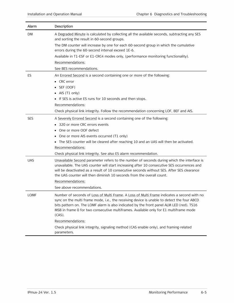
Installation and Operation Manual Chapter 6 Diagnostics and Troubleshooting
IPmux-24 Ver. 1.5 Monitoring Performance 6-5
Alarm Description
DM A Degraded Minute is calculated by collecting all the available seconds, subtracting any SES
and sorting the result in 60-second groups.
The DM counter will increase by one for each 60-second group in which the cumulative
errors during the 60-second interval exceed 1E-6.
Available in T1-ESF or E1-CRC4 modes only, (performance monitoring functionality).
Recommendations:
See BES recommendations.
ES An Errored Second is a second containing one or more of the following:
• CRC error
• SEF (OOF)
• AIS (T1 only)
• If SES is active ES runs for 10 seconds and then stops.
Recommendations:
Check physical link integrity. Follow the recommendation concerning LOF, BEF and AIS.
SES A Severely Errored Second is a second containing one of the following:
• 320 or more CRC errors events
• One or more OOF defect
• One or more AIS events occurred (T1 only)
• The SES counter will be cleared after reaching 10 and an UAS will then be activated.
Recommendations:
Check physical link integrity. See also ES alarm recommendation.
UAS Unavailable Second parameter refers to the number of seconds during which the interface is
unavailable. The UAS counter will start increasing after 10 consecutive SES occurrences and
will be deactivated as a result of 10 consecutive seconds without SES. After SES clearance
the UAS counter will then diminish 10 seconds from the overall count.
Recommendations:
See above recommendations.
LOMF Number of seconds of Loss of Multi Frame. A Loss of Multi Frame indicates a second with no
sync on the multi frame mode, i.e., the receiving device is unable to detect the four ABCD
bits pattern on. The LOMF alarm is also indicated by the front panel ALM LED (red). TS16
MSB in frame 0 for two consecutive multiframes. Available only for E1 multiframe mode
(CAS).
Recommendations:
Check physical link integrity, signaling method (CAS enable only), and framing-related
parameters.
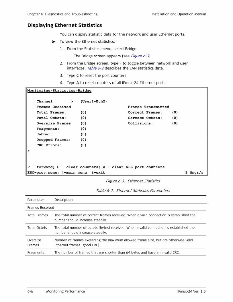
Chapter 6 Diagnostics and Troubleshooting Installation and Operation Manual
6-6 Monitoring Performance IPmux-24 Ver. 1.5
Displaying Ethernet Statistics
You can display statistic data for the network and user Ethernet ports.
To view the Ethernet statistics:
1. From the Statistics menu, select Bridge.
The Bridge screen appears (see Figure 6-3).
2. From the Bridge screen, type F to toggle between network and user interfaces. Table 6-2 describes the LAN statistics data.
3. Type C to reset the port counters.
4. Type A to reset counters of all IPmux-24 Ethernet ports.
Monitoring>Statistics>Bridge Channel > (User1-Eth2) Frames Received Frames Transmitted Total Frames: (0) Correct Frames: (0) Total Octets: (0) Correct Octets: (0) Oversize Frames (0) Collisions: (0) Fragments: (0) Jabber: (0) Dropped Frames: (0) CRC Errors: (0) > F - forward; C - clear counters; A - clear ALL port counters ESC-prev.menu; !-main menu; &-exit 1 Mngr/s
Figure 6-3. Ethernet Statistics
Table 6-2. Ethernet Statistics Parameters
Parameter Description
Frames Received
Total Frames The total number of correct frames received. When a valid connection is established the
number should increase steadily.
Total Octets The total number of octets (bytes) received. When a valid connection is established the
number should increase steadily.
Oversize
Frames
Number of frames exceeding the maximum allowed frame size, but are otherwise valid
Ethernet frames (good CRC).
Fragments The number of frames that are shorter than 64 bytes and have an invalid CRC.

Installation and Operation Manual Chapter 6 Diagnostics and Troubleshooting
IPmux-24 Ver. 1.5 Monitoring Performance 6-7
Parameter Description
Jabber The number of frames that are too long and have an invalid CRC.
A jabber is transmission by a data station beyond the time interval allowed by the protocol,
usually affecting the rest of the network. In an Ethernet network, devices compete for use
of the line, attempting to send a signal and then retrying in the event that someone else
tried at the same time. A jabber can look like a device that is always sending, effectively
bringing the network to a halt.
Recommendations
Check network interface card or any other transmitting devices and external electrical
interference.
Dropped
Frames
Number of dropped frames due to delivery problems.
Recommendations:
Check the network interface card.
CRC Errors The amount of frames with invalid CRCs.
Frames Transmitted
Correct
Frames
The number of frames successfully transmitted. When a valid connection is established the
number should increase steadily.
Correct
Octets
The number of octets successfully transmitted. When a valid connection is established the
number should increase steadily.
Collisions The number of successfully transmitted frames which transmission is inhibited by a collision
event. A collision occurs in half-duplex connection when two devices try to transmit at the
same time. This counter tracks the number of times frames have collided. This event exists
only in half duplex mode, which is not recommended in an IPmux-24 application.
Recommendations:
Many collisions indicate that the traffic is too heavy for a half-duplex media. Set to a Full-
Duplex environment if possible.
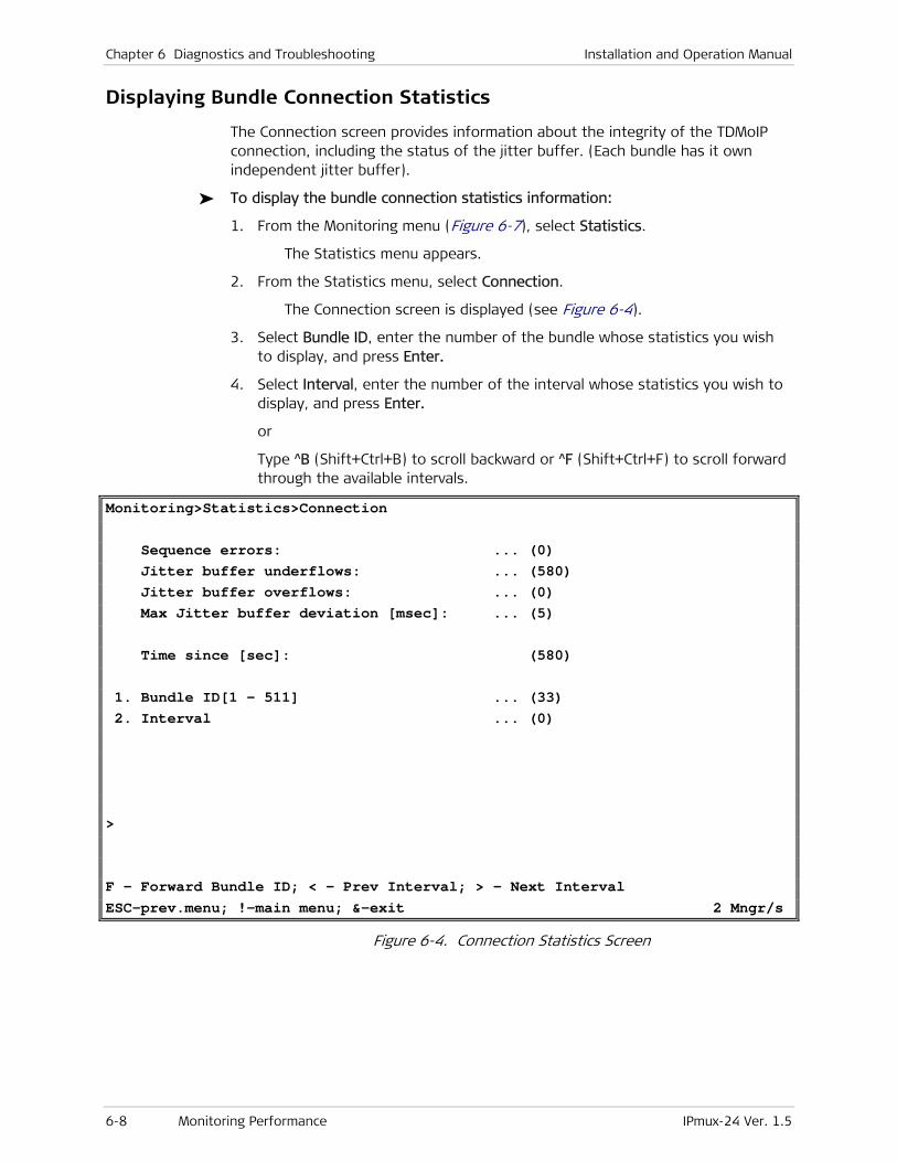
Chapter 6 Diagnostics and Troubleshooting Installation and Operation Manual
6-8 Monitoring Performance IPmux-24 Ver. 1.5
Displaying Bundle Connection Statistics
The Connection screen provides information about the integrity of the TDMoIP connection, including the status of the jitter buffer. (Each bundle has it own independent jitter buffer).
To display the bundle connection statistics information:
1. From the Monitoring menu (Figure 6-7), select Statistics.
The Statistics menu appears.
2. From the Statistics menu, select Connection.
The Connection screen is displayed (see Figure 6-4).
3. Select Bundle ID, enter the number of the bundle whose statistics you wish to display, and press Enter.
4. Select Interval, enter the number of the interval whose statistics you wish to display, and press Enter.
or
Type ^B (Shift+Ctrl+B) to scroll backward or ^F (Shift+Ctrl+F) to scroll forward through the available intervals.
Monitoring>Statistics>Connection Sequence errors: ... (0) Jitter buffer underflows: ... (580) Jitter buffer overflows: ... (0) Max Jitter buffer deviation [msec]: ... (5) Time since [sec]: (580) 1. Bundle ID[1 - 511] ... (33) 2. Interval ... (0) > F - Forward Bundle ID; < - Prev Interval; > - Next Interval ESC-prev.menu; !-main menu; &-exit 2 Mngr/s
Figure 6-4. Connection Statistics Screen

Installation and Operation Manual Chapter 6 Diagnostics and Troubleshooting
IPmux-24 Ver. 1.5 Monitoring Performance 6-9
Table 6-3. Bundle Connection Statistics Parameters
Parameter Description
Sequence
Errors
The number of seconds with sequence errors since the last clear.
Each packet transmitted by IPmux-24 holds a sequence number. The receiving IPmux-24 checks these
numbers at the receive mechanism and expects to see that each new incoming packet is “in
sequence” relative to the previous one (i.e., packet no. 5 is received after no. 4). When, for some
reason, this is not the case (i.e., next packet is not in sequence relative to the previous one), this
means that there had been a problem with packet flow integrity (and hence data/voice integrity).
IPmux will indicate this by increasing the “Sequence Errors” counter by one.
There may be two reasons for a Sequence Error notification:
Packet or packets are lost somewhere along the network.
Re-ordering of packets by network.
Packet re-ordering may occur due to queuing mechanisms, re-routing by the network, or when the
router updates very large routing tables.
Recommendations:
• Make sure IPmux-24 traffic has sufficient bandwidth.
• Make sure Ethernet connection is functioning properly (see Displaying Ethernet Statistics on
page 6-6.)
• Make sure Ethernet/IP network provides priority (Quality Of Service) to the IPmux traffic. Priority
may be achieved by three means: VLAN tagging, IP TOS marking or by using the constant 2142
decimal value at the “UDP destination Port” field of each TDMoIP packet.
• Verify that the IP network devices (switches/routers/modems/etc.) are capable of handling the
IPmux PPS rate (Packets Per Second).
• Make sure the network devices do not drop/lose/ignore packets.
Note: IPmux-24 may support a “reordering mechanism”, which can sort packets back to their original order in some situations.
Chapter 6 Diagnostics and Troubleshooting Installation and Operation Manual
6-10 Monitoring Performance IPmux-24 Ver. 1.5
Parameter Description
Jitter Buffer
Underflows
The number of seconds with jitter buffer underflows since the last clear.
IPmux-24 is equipped with a “Packet Delay Variation Tolerance” buffer, also called a “jitter buffer”,
responsible for compensating for IP networks delay variation (IP jitter). The jitter buffer is configured
in milliseconds units and exists for each bundle independently.
Explanation:
Packets leave the transmitting IPmux-24 at a constant rate, but the problem is that they are reaching
the opposite IPmux-24 at a rate which is NOT constant, due to network delay variation (caused by
congestion, re-routing, queuing mechanisms, wireless media, half-duplex media, etc.). The TDM
devices at both ends require a constant flow of data, so they can’t tolerate delay variation. Therefore
the jitter buffer is required in order to provide the TDM equipment with a synchronous and constant
flow.
This is done as follows:
• Upon startup, the jitter buffer stores packets up to its middle point (the number of packets
correlates to the buffer’s configured depth in milliseconds). Only after that point it starts
outputting the E1/T1 flow towards its adjacent TDM device. The stored packets assure that the
TDM device will be fed with data even if packets are delayed by the IP network. Obviously, if
packets are delayed too long, then the buffer is gradually emptied out until it is underflowed. This
situation is called buffer starvation. Each underflow event increases the jitter buffer underflow
counter by one and indicates a problem in the end-to-end voice/data integrity.
The second functionality of the jitter buffer is that in adaptive mode the jitter buffer is also a part of
a mechanism being used to reconstruct the clock of the far end TDM side.
An underflow situation can be a cause of:
• Buffer starvation: Packets delay variation causes the buffer to empty out gradually until it is
underflowed.
• Continuous Sequence Errors. The sequence error means a halt in the valid stream of packet arrival
into the jitter buffer.
• Packets are being stopped/lost/dropped.
• Too small jitter buffer configuration that can’t compensate for the network delay variation.
• When all system elements are not locked on the same master clock, it will lead to a situation in
which data is clocked out of the jitter buffer at a rate different from the one it is clocked into. This
will gradually result in either an overflow or underflow event, depending on which rate is higher.
The event will repeat itself periodically as long as the system clock is not locked.
• When an overflow (see below) situation occurs, IPmux-24 instantly flushes the jitter buffer, causing
a forced underflow. So when you need to calculate the real underflow events and not the
self-initiated ones, subtract the number of overflows from the total number of underflows counted
by the device.
Recommendations:
• Try increasing the jitter buffer size.
• Check reasons for sequence errors or lost/dropped packets (if present), system clocking
configuration, Ethernet environment (full duplex) and connection, packets drop/loss/ignore by
routers/switches or non-uniform packets output by routers/switches due to queuing mechanisms.
• Make sure the same amount of TS for bundle is configured on each side of the IPmux-24
application, and that the “TDM bytes in frame” parameter is identical in both IPmux-24 units.
• Make sure Ethernet/IP network provides priority (Quality Of Service) to the IPmux-24 traffic.
Priority may be achieved by three means: VLAN tagging, IP TOS marking or by using the constant
2142 decimal value at each IPmux “UDP destination Port” field.
Installation and Operation Manual Chapter 6 Diagnostics and Troubleshooting
IPmux-24 Ver. 1.5 Detecting Errors 6-11
Parameter Description
Jitter Buffer
Overflows
The number of seconds with at least one jitter buffer overflow event since the last clear.
Explanation:
In steady state, the jitter buffer is filled up to its middle point, which means it has the space to hold
an additional similar quantity of packets. Overflow is opposite phenomenon of the Underflow, i.e.,
when a big burst of packets reaches the IPmux (a burst with more packets than the Jitter Buffer can
store), the buffer will be filled up to its top. In this case, an unknown number of excessive packets
are dropped and hence IPmux initiates a forced underflow by flushing (emptying) the buffer in order
to start fresh from the beginning. An overflow situation always results in an immediate Underflow,
forced by the IPmux. After the buffer is flushed, the process of filling up the buffer is started again,
as explained above (“Underflow” section).
An overflow situation can be a cause of:
• A big burst of packets, filling up the buffer completely. The burst itself can often be a cause of
some element along the IP network queuing the packets and then transmitting them all at once.
• Too small jitter buffer configuration.
• When system isn’t locked on the same clock, it will lead to a situation in which data is clocked out
of the jitter buffer at a rate different from the one it is clocked into. This will gradually result in
either an overflow or underflow event, depending on which rate is higher. The event will repeat
itself periodically as long as the system clock is not locked.
Recommendations:
Check network devices and try increasing jitter buffer configuration.
Check system’s clocking configuration
Make sure the same amount of TS for bundle is configured on each side of the IPmux-24 application,
and that the “TDM bytes in frame” parameter is identical in both IPmux-24 units
Max Jitter
Buffer
Deviation
The maximum jitter buffer deviation (msec) in the interval (300 sec). This is the maximum jitter level
IPmux-24 had to compensate for in the selected interval.
Time Since
(sec)
The time elapsed, in seconds, since the beginning of the selected interval.
6.2 Detecting Errors
Power-Up Self-Test
IPmux-24 performs hardware self-test upon turn-on. The self-test sequence checks the critical circuit functions of IPmux-24 (framer and bridge). The self-test results are displayed via the Diagnostics menu.
To display the self-test results:
1. From the Main menu, select Diagnostics.
2. The Diagnostics menu appears (see Figure 6-5). From the Diagnostics menu, select Self Test Results.
The Self Test Results screen appears (see Figure 6-6).
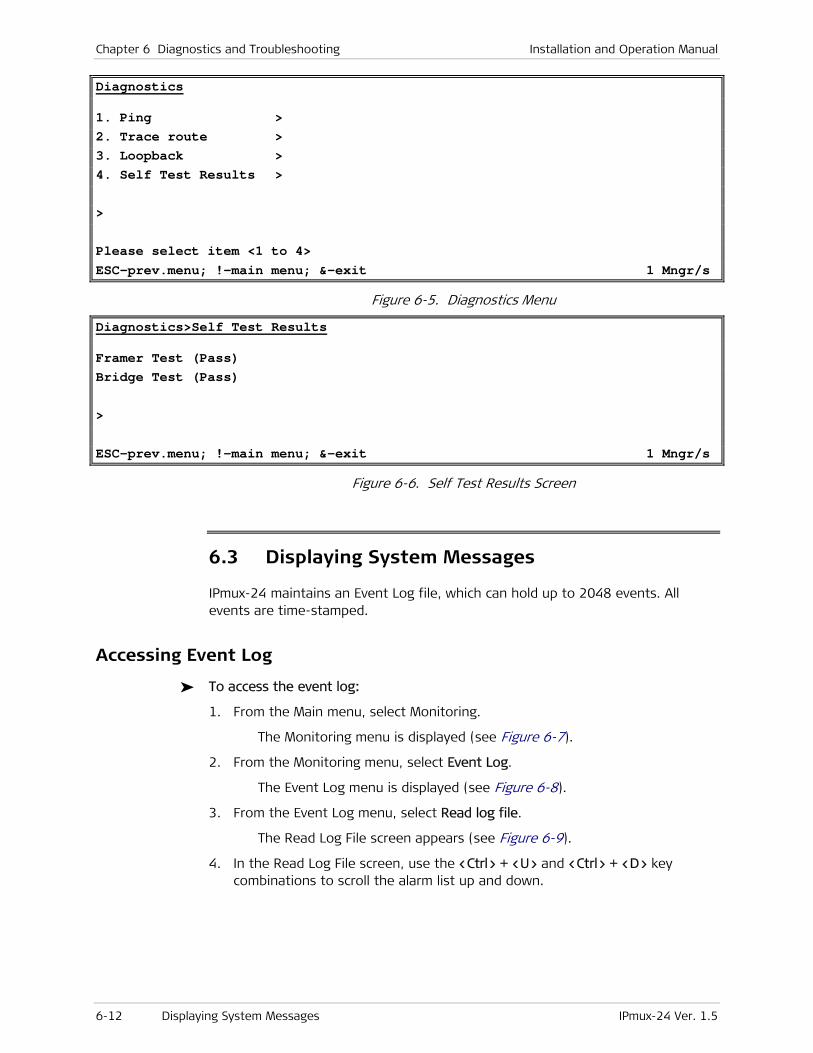
Chapter 6 Diagnostics and Troubleshooting Installation and Operation Manual
6-12 Displaying System Messages IPmux-24 Ver. 1.5
Diagnostics
1. Ping > 2. Trace route > 3. Loopback > 4. Self Test Results > > Please select item <1 to 4> ESC-prev.menu; !-main menu; &-exit 1 Mngr/s
Figure 6-5. Diagnostics Menu
Diagnostics>Self Test Results
Framer Test (Pass) Bridge Test (Pass) > ESC-prev.menu; !-main menu; &-exit 1 Mngr/s
Figure 6-6. Self Test Results Screen
6.3 Displaying System Messages
IPmux-24 maintains an Event Log file, which can hold up to 2048 events. All events are time-stamped.
Accessing Event Log
To access the event log:
1. From the Main menu, select Monitoring.
The Monitoring menu is displayed (see Figure 6-7).
2. From the Monitoring menu, select Event Log.
The Event Log menu is displayed (see Figure 6-8).
3. From the Event Log menu, select Read log file.
The Read Log File screen appears (see Figure 6-9).
4. In the Read Log File screen, use the <Ctrl> + <U> and <Ctrl> + <D> key combinations to scroll the alarm list up and down.
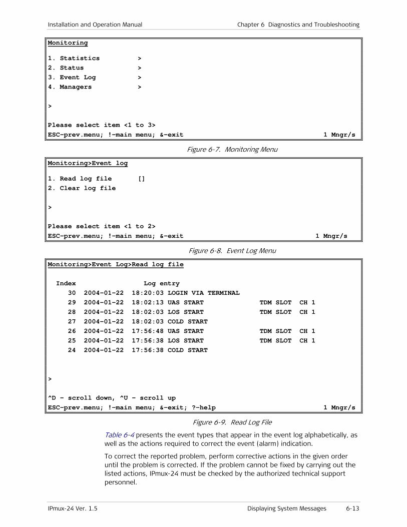
Installation and Operation Manual Chapter 6 Diagnostics and Troubleshooting
IPmux-24 Ver. 1.5 Displaying System Messages 6-13
Monitoring
1. Statistics > 2. Status > 3. Event Log > 4. Managers > > Please select item <1 to 3> ESC-prev.menu; !-main menu; &-exit 1 Mngr/s
Figure 6-7. Monitoring Menu
Monitoring>Event log
1. Read log file [] 2. Clear log file > Please select item <1 to 2> ESC-prev.menu; !-main menu; &-exit 1 Mngr/s
Figure 6-8. Event Log Menu
Monitoring>Event Log>Read log file Index Log entry 30 2004-01-22 18:20:03 LOGIN VIA TERMINAL 29 2004-01-22 18:02:13 UAS START TDM SLOT CH 1 28 2004-01-22 18:02:03 LOS START TDM SLOT CH 1 27 2004-01-22 18:02:03 COLD START 26 2004-01-22 17:56:48 UAS START TDM SLOT CH 1 25 2004-01-22 17:56:38 LOS START TDM SLOT CH 1 24 2004-01-22 17:56:38 COLD START > ^D - scroll down, ^U - scroll up ESC-prev.menu; !-main menu; &-exit; ?-help 1 Mngr/s
Figure 6-9. Read Log File
Table 6-4 presents the event types that appear in the event log alphabetically, as well as the actions required to correct the event (alarm) indication.
To correct the reported problem, perform corrective actions in the given order until the problem is corrected. If the problem cannot be fixed by carrying out the listed actions, IPmux-24 must be checked by the authorized technical support personnel.

Chapter 6 Diagnostics and Troubleshooting Installation and Operation Manual
6-14 Displaying System Messages IPmux-24 Ver. 1.5
Clearing Events
To clear the event log:
1. From the Event Log menu, select Clear log file.
IPmux-24 displays the following message: Logfile will be cleared. Continue ??? (Y/N)
2. Type Y to confirm the log file clearing.
Table 6-4. Event List
Event Description Corrective Action
COLD START IPmux-24 has been powered up None
CON LOCAL FAIL Ethernet frames are not received by the
local IPmux-24 on the specified connection
Check Ethernet/IP path
CON REMOTE FAIL Ethernet frames are not received by the
remote IPmux-24 on the specified
connection
Check Ethernet/IP path
CON SYNC Bundle connection failure has ended (only
applicable when OAM is Enabled)
None
CON UNAVAILABLE Remote IPmux is not available (only
applicable when OAM is Enabled)
Check the connection of the
remote IPmux
CON VALIDATION FAIL Connection is invalid (only applicable when
OAM is Enabled)
Check the bundle parameters
FATAL ERROR IPmux-24 has encountered an internal
fatal error
The IPmux-24 requires servicing
IN BAND REMOTE LOOP
START
T1 inband loopback has been activated on
remote IPmux-24
None
IN BAND REMOTE LOOP
END
T1 inband loopback has been deactivated
on remote IPmux-24
None
IN BAND LOCAL LOOP
START
T1 inband loopback has been activated on
local IPmux-24
None
IN BAND LOCAL LOOP
END
T1 inband loopback has been deactivated
on local IPmux-24
None
INVALID LOGIN VIA
TERMINAL
Invalid user name or password was
entered, when attempting to access
IPmux-24 via local terminal
None
INVALID LOGIN VIA WEB Invalid user name or password was
entered, when attempting to access
IPmux-24 via Web browser
None
INVALID LOGIN VIA
TELNET
Invalid user name or password was
entered, when attempting to access
IPmux-24 via Telnet
None

Installation and Operation Manual Chapter 6 Diagnostics and Troubleshooting
IPmux-24 Ver. 1.5 Displaying System Messages 6-15
Event Description Corrective Action
IP x.x.x.x ASSIGNED BY
SERVER x.x.x.x
The current IP address was assigned the
IPmux-24 host by DHCP server
None
IP x.x.x.x IS RELEASED The current IP address was released by
IPmux-24
None
LINE AIS END Line AIS state detected has ended None
LINE AIS START IPmux-24 has AIS (alarm indicator signal)
state on its E1/T1 port
Check for a fault at the PDH
network, on the receive direction
LINE FEBE END LINE FEBE state detected has ended None
LINE FEBE START IPmux-24 has LINE FEBE state on its E1/T1
port
Check for errors in the E1/T1
connection on the transmit
direction
LINE RAI END LINE RAI state detected has ended None
LINE RAI START IPmux-24 has LINE RAI (remote alarm
indication) state on its E1/T1 port
Check for a fault at the E1/T1
connectivity on the transmit
direction
LOGIN VIA TERMINAL The unit was accessed via local terminal None
LOGIN VIA WEB The unit was accessed via Web browser None
LOGIN VIA TELNET The unit was accessed via Telnet None
LOF START IPmux-24 has a LOF (loss of frame) state
on its E1/T1 port 1. Check the E1/T1 cable
connection.
2. Check all framing-related
parameters for E1/T1 interface.
LOF END LOF state detected has ended None
LOS END LOS state detected has ended None
LOS START IPmux-24 has a LOS (loss of signal) state
on its E1/T1 port 1. Check the E1/T1 cable
connection.
3. Check input signal.
PS ACTIVE IPmux-24 power supply unit is powered on None
SYSTEM USER RESET The user initiated software reset via the
system menu None
UAS START Ten consecutive severely errored seconds
were detected Check physical interface
connections.
UAS END Ten consecutive seconds without SES were
detected None

Chapter 6 Diagnostics and Troubleshooting Installation and Operation Manual
6-16 Displaying System Messages IPmux-24 Ver. 1.5
Masking Alarm Traps
You can mask some IPmux-24 alarm traps to prevent it from being sent to the management stations.
To mask alarms:
1. From the Management menu, select Alarm trap mask.
The Alarm Trap Mask menu appears (see Figure 6-10).
2. From the Alarm Traps Mask menu, select Alarm ID to choose alarm that you intend to mask.
List of the alarm traps can be displayed by typing ?.
3. Select Trap Status to enable or disable masking of the selected alarm.
Configuration>System>Management>Alarm trap mask
Active alarm traps: > (-)
1. Alarm ID <use 'help'>[1 - 40] ... (39) 2. Trap status (Masked) > Please select item <1 to 2> S - Save; ? - Help ESC-prev.menu; !-main menu; &-exit 1 Mngr/s
Figure 6-10. Alarm Trap Mask Menu
Table 6-5. Trap List
Trap Description, Severity OID
alarmLOS Loss of Signal (LOS Physical Layer), major 1.3.6.1.4.1.164.6.1.3.0.7
alarmLOF Loss of Frame (LOF Physical Layer), major 1.3.6.1.4.1.164.6.1.3.0.8
alarmAIS Alarm Indication Signal Received (AIS Line Physical
Layer), major
1.3.6.1.4.1.164.6.1.3.0.10
alarmRDI Remote Defect Indication Received (RDI Line
Physical Layer), major
1.3.6.1.4.1.164.6.1.3.0.11
alarmFEBE Far End Block Error (FEBE Line Layer), major 1.3.6.1.4.1.164.6.1.3.0.12
alarmExtClk External clock source has failed, minor 1.3.6.1.4.1.164.6.1.0.10
BundleConenctionStatus Bundle connectivity status:
• O.K – major
• Remote fail – minor
• Local fail – major
• Validation Fail – major
• Unavailable – major
1.3.6.1.4.1.164.6.1.3.0.15
Note
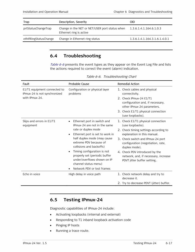
Installation and Operation Manual Chapter 6 Diagnostics and Troubleshooting
IPmux-24 Ver. 1.5 Testing IPmux-24 6-17
Trap Description, Severity OID
prtStatusChangeTrap Change in the NET or NET/USER port status when
Ethernet ring is active
1.3.6.1.4.1.164.6.1.0.3
ethIfRingStatusChange Change in Ethernet ring status 1.3.6.1.4.1.164.3.1.6.1.4.0.1
6.4 Troubleshooting
Table 6-6 presents the event types as they appear on the Event Log File and lists the actions required to correct the event (alarm) indication.
Table 6-6. Troubleshooting Chart
Fault Probable Cause Remedial Action
E1/T1 equipment connected to
IPmux-24 is not synchronized
with IPmux-24.
Configuration or physical layer
problems
1. Check cables and physical
connectivity.
2. Check IPmux-24 E1/T1
configuration and, if necessary,
other IPmux-24 parameters.
3. Check E1/T1 physical connection
(use loopbacks).
Slips and errors in E1/T1
equipment
• Ethernet port in switch and
IPmux-24 are not in the same
rate or duplex mode
• Ethernet port is set to work in
half duplex mode (may cause
extreme PDV because of
collisions and backoffs)
• Timing configuration is not
properly set (periodic buffer
under/overflows shown on IP
channel status menu)
• Network PDV or lost frames
1. Check E1/T1 physical connection
(use loopbacks).
2. Check timing settings according to
explanation in this manual.
3. Check switch and IPmux-24 port
configuration (negotiation, rate,
duplex mode).
4. Check PDV introduced by the
network, and, if necessary, increase
PDVT jitter buffer setting..
Echo in voice High delay in voice path 1. Check network delay and try to
decrease it.
2. Try to decrease PDVT (jitter) buffer.
6.5 Testing IPmux-24
Diagnostic capabilities of IPmux-24 include:
• Activating loopbacks (internal and external)
• Responding to T1 inband loopback activation code
• Pinging IP hosts
• Running a trace route.
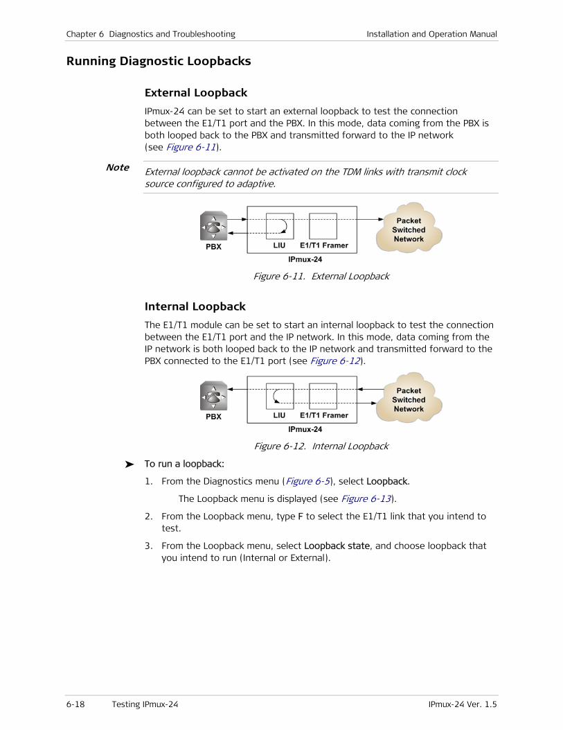
Chapter 6 Diagnostics and Troubleshooting Installation and Operation Manual
6-18 Testing IPmux-24 IPmux-24 Ver. 1.5
Running Diagnostic Loopbacks
External Loopback
IPmux-24 can be set to start an external loopback to test the connection between the E1/T1 port and the PBX. In this mode, data coming from the PBX is both looped back to the PBX and transmitted forward to the IP network (see Figure 6-11).
External loopback cannot be activated on the TDM links with transmit clock source configured to adaptive.
Figure 6-11. External Loopback
Internal Loopback
The E1/T1 module can be set to start an internal loopback to test the connection between the E1/T1 port and the IP network. In this mode, data coming from the IP network is both looped back to the IP network and transmitted forward to the PBX connected to the E1/T1 port (see Figure 6-12).
Figure 6-12. Internal Loopback
To run a loopback:
1. From the Diagnostics menu (Figure 6-5), select Loopback.
The Loopback menu is displayed (see Figure 6-13).
2. From the Loopback menu, type F to select the E1/T1 link that you intend to test.
3. From the Loopback menu, select Loopback state, and choose loopback that you intend to run (Internal or External).
Note

Installation and Operation Manual Chapter 6 Diagnostics and Troubleshooting
IPmux-24 Ver. 1.5 Testing IPmux-24 6-19
Diagnostics>Loopback Channel ID (1)
1. Loopback State > (External) > F - forward; S - save Please select item <1 to 1> ESC-prev.menu; !-main menu; &-exit 1 Mngr/s
Figure 6-13. Loopback Menu
To disable a loopback:
• From the Loopback menu, select Loopback state, and set it to Disable.
To display the diagnostic loopback status:
• From the Status menu, select Diagnostics loopback.
Monitoring>Status>Diagnostics loopback Channel ID (1) Loopback state: > (Disable) > ESC-prev.menu; !-main menu; &-exit 1 Mngr/s
Figure 6-14. Diagnostic Loopback Screen
Activating T1 Inband Loopbacks
T1 physical loopbacks can be activated by receiving a loopback activation code from TDM equipment connected to the T1 port. When IPmux-24 receives a loopback activation code, it closes an external loopback (see Figure 6-15), or translates the TDM-based loopback activation code into the packet-based pattern and sends it to the opposite IPmux device, which closes an internal loopback (see Figure 6-16).
The inband loopback can be activated only if the OAM connectivity is enabled and only one bundle is configured for each port of the device.
An inband loopback is deactivated automatically, if:
• TDM connection is down
• Ethernet connection is down
• The user activated an internal or external loopback manually.
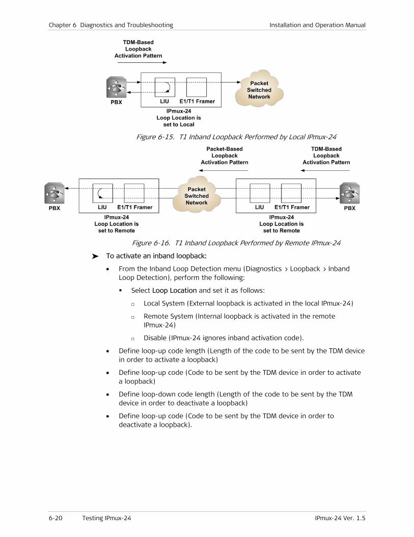
Chapter 6 Diagnostics and Troubleshooting Installation and Operation Manual
6-20 Testing IPmux-24 IPmux-24 Ver. 1.5
Figure 6-15. T1 Inband Loopback Performed by Local IPmux-24
Figure 6-16. T1 Inband Loopback Performed by Remote IPmux-24
To activate an inband loopback:
• From the Inband Loop Detection menu (Diagnostics > Loopback > Inband Loop Detection), perform the following:
Select Loop Location and set it as follows:
Local System (External loopback is activated in the local IPmux-24)
Remote System (Internal loopback is activated in the remote IPmux-24)
Disable (IPmux-24 ignores inband activation code).
• Define loop-up code length (Length of the code to be sent by the TDM device in order to activate a loopback)
• Define loop-up code (Code to be sent by the TDM device in order to activate a loopback)
• Define loop-down code length (Length of the code to be sent by the TDM device in order to deactivate a loopback)
• Define loop-up code (Code to be sent by the TDM device in order to deactivate a loopback).

Installation and Operation Manual Chapter 6 Diagnostics and Troubleshooting
IPmux-24 Ver. 1.5 Testing IPmux-24 6-21
Diagnostics>Loopback (T1)>Inband Loop Detection
1. Loop Location > (Local System) 2. Loop up length[1 - 8] ... (5) 3. Loop up code[Hex] ... (10) 4. Loop down length[1 - 8] ... (3) 5. Loop down code[Hex] ... (4) > Please select item <1 to 5> ESC-prev.menu; !-main menu; &-exit 1 Mngr/s
Figure 6-17. Inband Loop Detection Menu
Pinging IP Hosts
You can ping remote IP host to check the IPmux-24 IP connectivity.
To ping an IP host:
1. From the Diagnostics menu (Figure 6-5), select Ping.
The Ping menu appears (see Figure 6-18).
2. From the Ping menu, configure the following:
Interface (Direction (switch port), to which the ping is sent):
System host IP (IPmux-24 sends ping to an IP address in the management subnet)
PW host IP (IPmux-24 sends ping to an IP address in the PW traffic subnet)
Destination IP Address (IP address of the host that you intend to ping): 0.0.0.0 to 255.255.255.255.
VLAN Tagging:
Enable (VLAN tagging is enabled)
Disable (VLAN tagging is disabled)
VLAN ID: 1–4095
VLAN Priority: 0–7
The VLAN ID and VLAN Priority configuration is available only if the VLAN tagging is enabled.
Number of frames to send: 1–4.
3. Select Ping Send to start sending pings.
Note
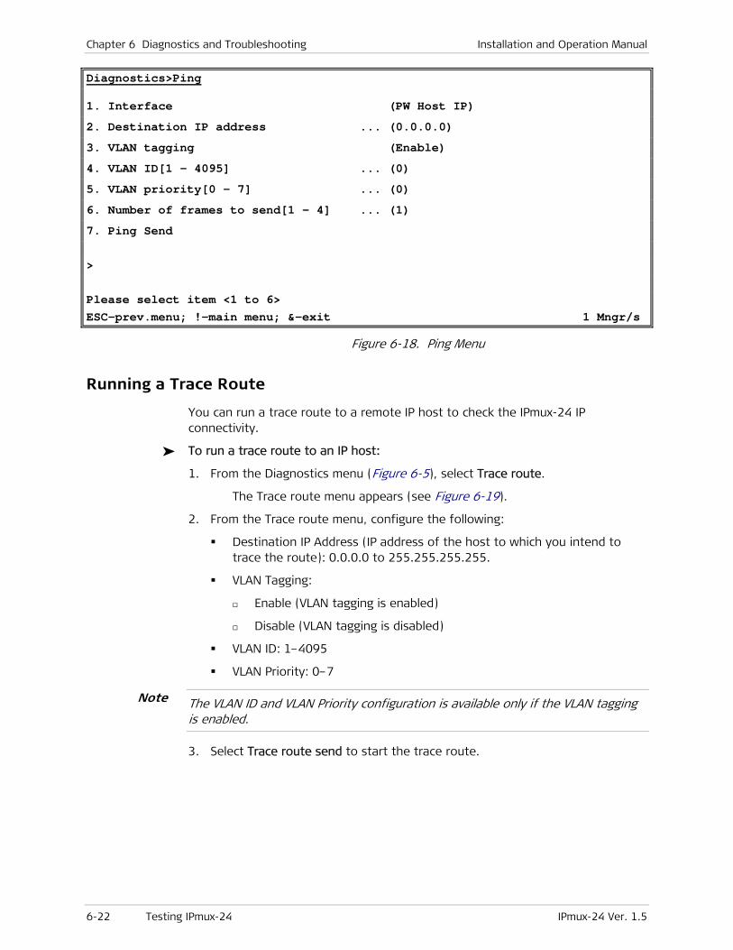
Chapter 6 Diagnostics and Troubleshooting Installation and Operation Manual
6-22 Testing IPmux-24 IPmux-24 Ver. 1.5
Diagnostics>Ping
1. Interface (PW Host IP) 2. Destination IP address ... (0.0.0.0) 3. VLAN tagging (Enable) 4. VLAN ID[1 - 4095] ... (0) 5. VLAN priority[0 - 7] ... (0) 6. Number of frames to send[1 - 4] ... (1) 7. Ping Send > Please select item <1 to 6> ESC-prev.menu; !-main menu; &-exit 1 Mngr/s
Figure 6-18. Ping Menu
Running a Trace Route
You can run a trace route to a remote IP host to check the IPmux-24 IP connectivity.
To run a trace route to an IP host:
1. From the Diagnostics menu (Figure 6-5), select Trace route.
The Trace route menu appears (see Figure 6-19).
2. From the Trace route menu, configure the following:
Destination IP Address (IP address of the host to which you intend to trace the route): 0.0.0.0 to 255.255.255.255.
VLAN Tagging:
Enable (VLAN tagging is enabled)
Disable (VLAN tagging is disabled)
VLAN ID: 1–4095
VLAN Priority: 0–7
The VLAN ID and VLAN Priority configuration is available only if the VLAN tagging is enabled.
3. Select Trace route send to start the trace route.
Note
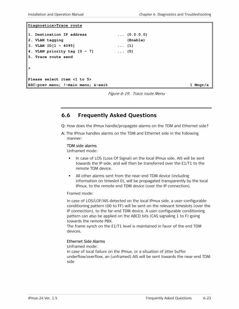
Installation and Operation Manual Chapter 6 Diagnostics and Troubleshooting
IPmux-24 Ver. 1.5 Frequently Asked Questions 6-23
Diagnostics>Trace route
1. Destination IP address ... (0.0.0.0) 2. VLAN tagging (Enable) 3. VLAN ID[1 - 4095] ... (1) 4. VLAN priority tag [0 - 7] ... (0) 5. Trace route send > Please select item <1 to 5> ESC-prev.menu; !-main menu; &-exit 1 Mngr/s
Figure 6-19. Trace route Menu
6.6 Frequently Asked Questions
Q: How does the IPmux handle/propagate alarms on the TDM and Ethernet side?
A: The IPmux handles alarms on the TDM and Ethernet side in the following manner:
TDM side alarms Unframed mode:
In case of LOS (Loss Of Signal) on the local IPmux side, AIS will be sent towards the IP side, and will then be transferred over the E1/T1 to the remote TDM device.
All other alarms sent from the near-end TDM device (including information on timeslot 0), will be propagated transparently by the local IPmux, to the remote end TDM device (over the IP connection).
Framed mode:
In case of LOS/LOF/AIS detected on the local IPmux side, a user-configurable conditioning pattern (00 to FF) will be sent on the relevant timeslots (over the IP connection), to the far-end TDM device. A user-configurable conditioning pattern can also be applied on the ABCD bits (CAS signaling 1 to F) going towards the remote PBX. The frame synch on the E1/T1 level is maintained in favor of the end TDM devices. Ethernet Side Alarms Unframed mode: In case of local failure on the IPmux, or a situation of jitter buffer underflow/overflow, an (unframed) AIS will be sent towards the near-end TDM side

Chapter 6 Diagnostics and Troubleshooting Installation and Operation Manual
6-24 Frequently Asked Questions IPmux-24 Ver. 1.5
Framed mode: In case of local failure on the IPmux, or situation of jitter buffer underflow/overflow, a conditioning pattern (00 to FF) will be sent towards the near-end TDM device on the timeslots related to that specific bundle. A user-configurable conditioning pattern can also be applied on the ABCD bits (CAS signaling 1 to F), going towards the local TDM device. In this case the synch on the E1/T1 level is maintained in favor of the TDM end devices.
Q: How can I ensure the IPmux TDMoIP traffic priority over an IP Ethernet network?
A: The IPmux units offer three different methods of the TDMoIP traffic prioritization over an IP/Ethernet network:
VLAN ID (Layer 2)
ToS field (Layer 3)
UDP destination port (Layer 4).
Each QoS feature is based on a different OSI level and can be used individually in order to ensure the TDMoIP traffic priority. When determining which feature to use, it is important to verify that the different elements on the network, (switches / routers / etc.), support the selected priority mechanism and are also configured to give the highest priority to the labeled IPmux traffic. Notice that the priority is given to the TDMoIP traffic by the network elements and the IPmux is merely tagging the packets.
VLAN ID The IPmux complies with the IEEE 802.1p&Q standards. This enables the user to set both VLAN ID and VLAN Priority. It adds four bytes to the MAC layer (Layer 2) of the Ethernet frame. These bytes contain information about the VLAN ID, and the VLAN priority, which runs from 0–7. The IPmux only tags the packets, while the switches are responsible for giving the priority according to the VLAN info. Verify that the IPmux traffic has the highest priority in the relevant Ethernet network.
ToS There are several RFCs (RFC791, RFC1349, RFC2474) that define how the IP ToS should be configured. The ToS is a byte located in the IP header (Layer 3). In general the Type of Service octet, in most cases, consists of three fields: The first field, labeled "PRECEDENCE", is intended to denote the importance or priority of the datagram. The second field, labeled "TOS", denotes how the network should make tradeoffs between throughput, delay, reliability, and cost. The last field, labeled "MBZ" (for "must be zero") above, is currently unused. The IPmux can configure the whole IP ToS byte, and therefore it is adaptable to each RFC in the market. The IP ToS parameter in the IPmux is user-configured in terms of decimal value. However, on the frame itself it of course appears in binary format. The decimal value varies between 0 and 255 (8 bits).
A configuration example: Setting IP precedence of 101 and IP ToS of 1000 will give us the byte 10110000, which means that the IPmux IP ToS parameter should be configured to 176 decimals.
Installation and Operation Manual Chapter 6 Diagnostics and Troubleshooting
IPmux-24 Ver. 1.5 Frequently Asked Questions 6-25
UDP Destination Port The IPmux uses the UDP protocol (Layer 4) in order to transfer the TDMoIP traffic. In the UDP protocol, the Destination port field is always set to the decimal value of 2142, hence all the packets leaving the IPmux are tagged accordingly. This unique value was assigned to RAD by the IANA organization for TDMoIP applications. The network elements may be used to give priority to the TDMoIP traffic according to the UDP destination field.
Q: Does allocating a sufficient bandwidth ensure the proper functionality of an IPmux-based application?
A: A sufficient bandwidth is not enough to ensure a steady environment for the IPmux, since networks loaded with additional non-IPmux LAN traffic (e.g. PC traffic) or incompetent Ethernet/IP network may cause several problems:
Jitter – The IPmux packets may suffer a delay variation (although all the traffic will eventually pass through due to that fact that there is sufficient bandwidth). Packets will be delayed for different periods of time due to overloaded networks, queuing mechanisms, etc. IPmux can compensate for some jitter (IPmux-1, IPmux-11 up to 300 msec, IPmux-14 up to 180 msec, IPmux-8/16 up to 32 msec for E1 and 24 msec for T1) but bigger jitter causes problems.
Misordering – Packets might be sent in different order than the order in which they were originally sent from the IPmux.
Packet Loss – Packets might be dropped/ignored by some elements in the network (routers/switches) due to insufficient processing power to handle the load, queuing mechanisms, buffer overflows, etc.
Normally these problems are solved by giving priority to the IPmux traffic over all other traffic. As can be shown, even though there is sufficient bandwidth, there might still be cases in which the traffic will be transmitted from all the sources at the same time and thus create a momentary load on the network element (router/switch), even when this load that does not exceed the available bandwidth. Since the IPmux is constantly transmitting, the TDMoIP traffic will always be a part of such a load. When no priority is given to the TDMoIP traffic, the network elements will handle the TDMoIP traffic as any other type of traffic. All the above degrade the performance of the IPmux unit, although an adequate amount of bandwidth is provided for the IPmux. Refer to FAQ 3338 to understand how to check the IPmux and network performance and how to solve problems.

Chapter 6 Diagnostics and Troubleshooting Installation and Operation Manual
6-26 Technical Support IPmux-24 Ver. 1.5
6.7 Technical Support
Technical support for this product can be obtained from the local distributor from whom it was purchased.
For further information, please contact the RAD distributor nearest you or one of RAD's offices worldwide. This information can be found at www.rad.com (offices – About RAD > Worldwide Offices; distributors – Where to Buy > End Users).

IPmux-24 Ver. 1.5 E1 and T1 Connector A-1
Appendix A
Connector Wiring
A.1 E1 and T1 Connector
Balanced Connector
The E1 and T1 interfaces of IPmux-24 terminate in 8-pin RJ-45 connectors, wired in accordance with Table A-1.
Table A-1. E1/T1 Port Connector Pinout
Pin Designation Direction Function
1 RD (R) Input Receive data (ring)
2 RD (T) Input Receive data (tip)
3, 6 – – FGND
4 TD (R) Output Transmit data (ring)
5 TD (T) Output Transmit data (tip)
7, 8 – N/A Not connected
Balanced-to-Unbalanced Adapter Cable
When IPmux-24 is ordered with unbalanced E1 interface, it is necessary to convert the RJ-45 connector to the standard pair of BNC female connectors used by unbalanced E1 interfaces. For that purpose, RAD offers a 150-mm long adapter cable, CBL-RJ45/2BNC/E1/X, wired in accordance with Figure A-1.
RJ-45
BNCFemale
Receive(Green)
Transmit(Red)
1
2
3
4
5
6
7
8
ShieldedRJ-45
Transmit(Red BNC)
Receive(Green BNC)
RX Ring
RX Tip
NC
TX Ring
TX Tip
NC
NC
NC
...
...
Figure A-1. CBL-RJ45/2BNC/E1/X Cable Wiring Diagram
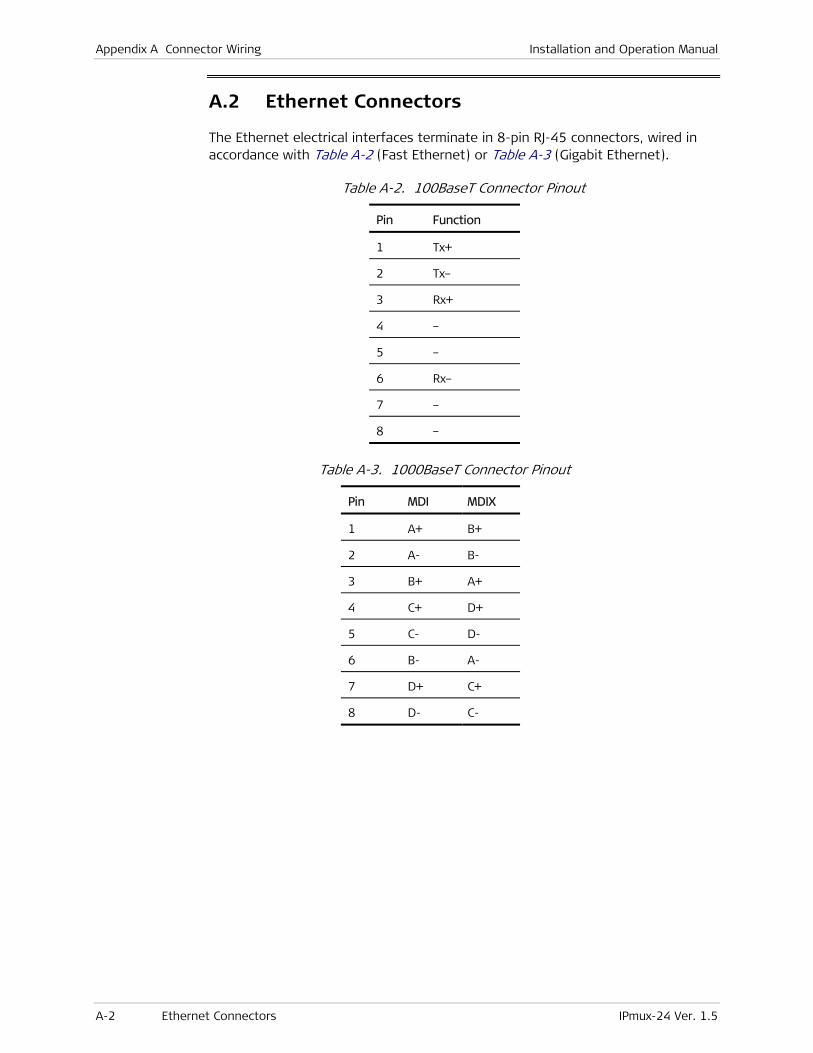
Appendix A Connector Wiring Installation and Operation Manual
A-2 Ethernet Connectors IPmux-24 Ver. 1.5
A.2 Ethernet Connectors
The Ethernet electrical interfaces terminate in 8-pin RJ-45 connectors, wired in accordance with Table A-2 (Fast Ethernet) or Table A-3 (Gigabit Ethernet).
Table A-2. 100BaseT Connector Pinout
Pin Function
1 Tx+
2 Tx–
3 Rx+
4 –
5 –
6 Rx–
7 –
8 –
Table A-3. 1000BaseT Connector Pinout
Pin MDI MDIX
1 A+ B+
2 A- B-
3 B+ A+
4 C+ D+
5 C- D-
6 B- A-
7 D+ C+
8 D- C-
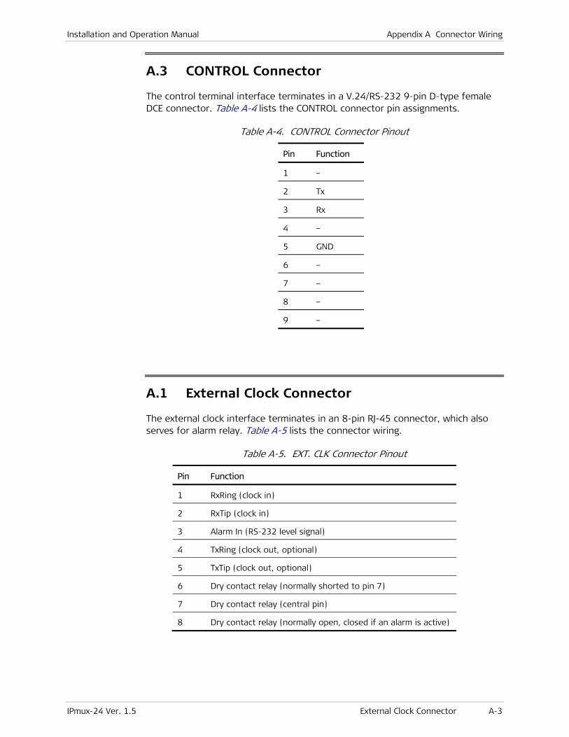
Installation and Operation Manual Appendix A Connector Wiring
IPmux-24 Ver. 1.5 External Clock Connector A-3
A.3 CONTROL Connector
The control terminal interface terminates in a V.24/RS-232 9-pin D-type female DCE connector. Table A-4 lists the CONTROL connector pin assignments.
Table A-4. CONTROL Connector Pinout
Pin Function
1 –
2 Tx
3 Rx
4 –
5 GND
6 –
7 –
8 –
9 –
A.1 External Clock Connector
The external clock interface terminates in an 8-pin RJ-45 connector, which also serves for alarm relay. Table A-5 lists the connector wiring.
Table A-5. EXT. CLK Connector Pinout
Pin Function
1 RxRing (clock in)
2 RxTip (clock in)
3 Alarm In (RS-232 level signal)
4 TxRing (clock out, optional)
5 TxTip (clock out, optional)
6 Dry contact relay (normally shorted to pin 7)
7 Dry contact relay (central pin)
8 Dry contact relay (normally open, closed if an alarm is active)
Appendix A Connector Wiring Installation and Operation Manual
A-4 Alarm Relay IPmux-24 Ver. 1.5
A.2 Alarm Relay
IPmux-24 supports dry contact alarm relay via dedicated pins 6, 7 and 8 of the RJ-45 EXT. CLK connector (see Table A-5).

IPmux-24 Ver. 1.5 Booting IPmux-24 B-1
Appendix B
Boot Sequence and Downloading Software This appendix provides a description of the IPmux-24 boot procedure via an ASCII terminal for downloading software.
The file system can hold two compressed copies of the IPmux-24 code. One copy is called the operating file, and the other is called the backup file. The operating file is the default-executable IPmux-24 code. The backup file is used whenever the operating file is absent or corrupted.
B.1 Booting IPmux-24 IPmux-24 boots up automatically. After powering up, no user intervention is required, except when the user wants to access the file system to modify or update the software or the IPmux-24 configuration.
Accessing the Boot Manager
The Boot Manager menu is an option that allows the user to perform basic file transfer operations. These operations are all optional.
To access the Boot Manager menu:
• Press <Enter> several times immediately after powering up the IPmux-24.
The Boot Manager menu is displayed (see Figure B-1).
IPMUX-24 Boot version 2.00 (Mar 6 2006) Boot manager version 7.04 (Mar 6 2006) 0 - Exit Boot-Manager 1 - Dir 2 - Set active software copy 3 - Delete software copy 4 - Download an application by XMODEM 5 - Format Flash 6 - Show basic hardware information 7 - Reset board 8 - System configuration. 9 - Download an application by TFTP Press the ESC key to go back to the main menu. Select:
Figure B-1. Boot Manager Menu
Appendix B Boot Sequence and Downloading Software Installation and Operation Manual
B-2 Downloading the Application and Configuration Software IPmux-24 Ver. 1.5
From the Boot Manager menu, you can:
• List all files stored in the flash memory
• Exchange the operating and backup files
• Delete the operating file; the backup file becomes the operating file
• Download a new operating file (via XMODEM or TFTP); the previous operating file is saved as the backup file
• Delete all software and configuration files
• Display the basic hardware information (RAM, ROM size etc)
• Reset the IPmux-24 board
• Configure the IPmux-24 IP address, IP mask and default gateway for the consecutive file download via TFTP.
If you choose to exchange or delete a file, you are prompted for confirmation.
B.2 Downloading the Application and Configuration Software
New application software releases are distributed as separate files, which are downloaded to IPmux-24 using the XMODEM protocol or TFTP from the Boot Manager menu. Alternatively, you can download a new software release via TFTP, when the IPmux-24 management software is already running (Main menu > Utilities > File Utilities > Download/Upload using TFTP).
The TFTP protocol can also be used for uploading configuration files, which contain the IPmux-24 database to the management station. Administrators can use this capability to distribute verified configuration files to all other units, which use the similar configuration.
Downloading Application Files via XMODEM
Downloading application files using the XMODEM protocol is performed from the Boot Manager menu.
To download application file via XMODEM:
1. Configure your ASCII terminal or terminal emulation utility running on your PC to the 115.2 kbps data rate.
2. Access the Boot Manager menu.
The Boot Manager menu appears (see Figure B-1).
3. From the Boot Manager menu, select Download an application by XMODEM.
IPmux-24 displays the following message: Select Copy number for download ( 0 )
4. Select the backup partition by typing its number, 0 or 1.
IPmux-24 responds with the following string: Please start the XMODEM download.
Installation and Operation Manual Appendix B Boot Sequence and Downloading Software
IPmux-24 Ver. 1.5 Downloading the Application and Configuration Software B-3
5. Send the software release file to IPmux-24 using the XMODEM utility of you terminal application.
Once the downloading is completed, IPmux-24 saves the new release as an active partition, the former active partition turns into backup, and the boot sequence continues normally.
If a failure occurs during the download, the partially downloaded software is erased. In this case, only active software is left in the flash memory.
Downloading Application Files via TFTP
To download application file via TFTP:
1. From the Boot Manager menu, select System Configuration.
2. Configure the IP parameters of IPmux-24 (IP address, IP mask and default gateway). These parameters are valid only for the TFTP file transfer via the Boot Manager.
3. Select Reset Board to reset the unit.
4. Start a TFTP application.
5. Select a local software release file to download.
6. Enter the IP address of the TFTP server.
7. Start downloading.
IPmux-24 automatically erases the backup partition (it takes about 25 seconds). Once the downloading is completed, IPmux-24 saves the new release as an active partition, the former active partition turns into backup.

Appendix B Boot Sequence and Downloading Software Installation and Operation Manual
B-4 Downloading the Application and Configuration Software IPmux-24 Ver. 1.5

Publication No. SUP-930-07/08
The Access Company
AC/DC Adapter(AD) Plug
for DC Power Supply Connection
Supplement
Ignore this supplement if the unit is AC-powered.
Certain units are equipped with a wide-range AC/DC power supply. These units are equipped with a standard AC-type 3-prong power input connector located on the unit rear panel. This power input connector can be used for both AC and DC voltage inputs.
For DC operation, a compatible straight or 90-degree AC/DC Adapter (AD) plug for attaching to your DC power supply cable is supplied with your RAD product (see Figure 1 and Figure 2).
Connect the wires of your DC power supply cable to the AD plug, according to the voltage polarity and assembly instructions provided on page 2.
Figure 1. Straight AD Plug
Figure 2. 90-Degree AD Plug
Prepare all connections to the AD plug before inserting it into the unit’s power connector.
Caution
Note
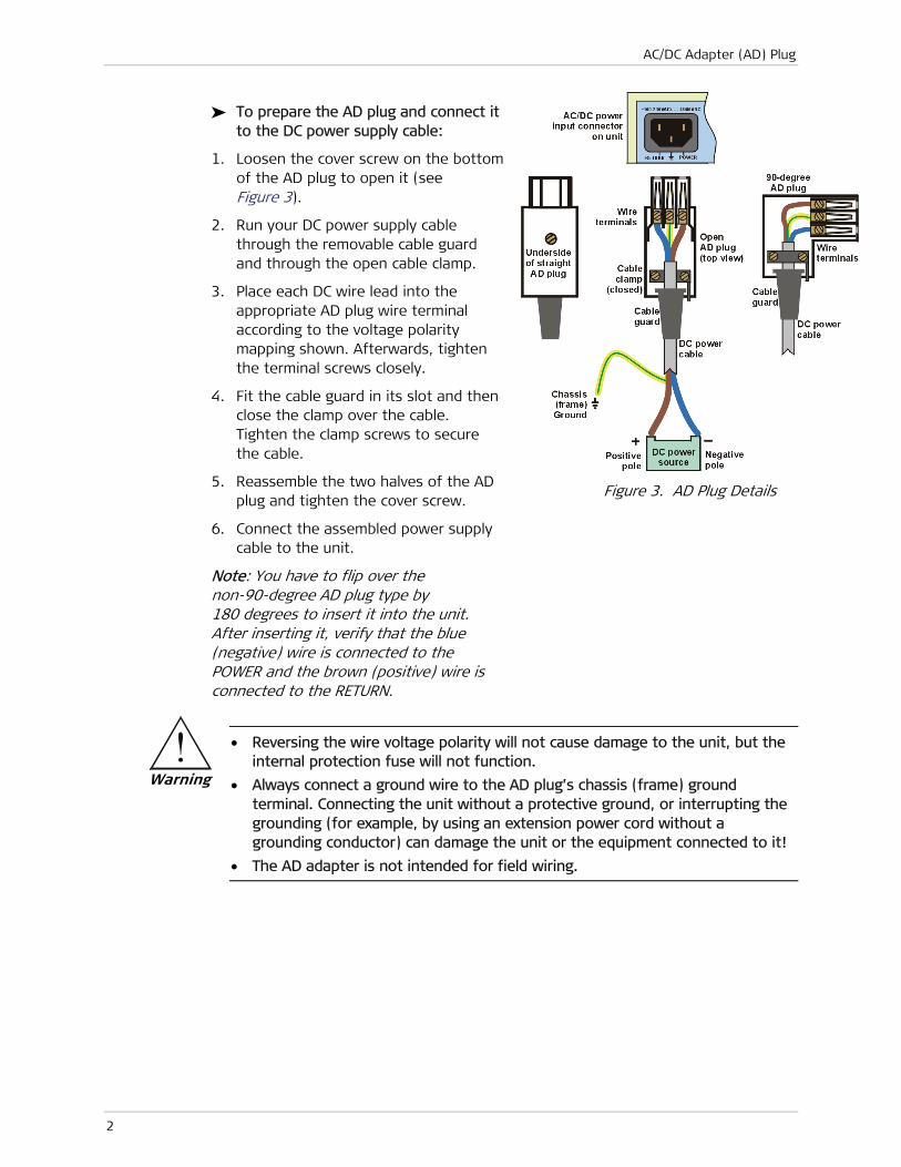
AC/DC Adapter (AD) Plug
2
To prepare the AD plug and connect it to the DC power supply cable:
1. Loosen the cover screw on the bottom of the AD plug to open it (see Figure 3).
2. Run your DC power supply cable through the removable cable guard and through the open cable clamp.
3. Place each DC wire lead into the appropriate AD plug wire terminal according to the voltage polarity mapping shown. Afterwards, tighten the terminal screws closely.
4. Fit the cable guard in its slot and then close the clamp over the cable. Tighten the clamp screws to secure the cable.
5. Reassemble the two halves of the AD plug and tighten the cover screw.
6. Connect the assembled power supply cable to the unit.
Note: You have to flip over the non-90-degree AD plug type by 180 degrees to insert it into the unit. After inserting it, verify that the blue (negative) wire is connected to the POWER and the brown (positive) wire is connected to the RETURN.
Figure 3. AD Plug Details
• Reversing the wire voltage polarity will not cause damage to the unit, but the internal protection fuse will not function.
• Always connect a ground wire to the AD plug’s chassis (frame) ground terminal. Connecting the unit without a protective ground, or interrupting the grounding (for example, by using an extension power cord without a grounding conductor) can damage the unit or the equipment connected to it!
• The AD adapter is not intended for field wiring.
Warning

24 Raoul Wallenberg Street, Tel Aviv 69719, Israel
Tel: +972-3-6458181, Fax +972-3-6483331, +972-3-6498250
E-mail: [email protected], Web site: http://www.rad.com
Customer Response Form
RAD Data Communications would like your help in improving its product documentation. Please complete and return this form by mail or by fax or send us an e-mail with your comments.
Thank you for your assistance!
Manual Name: IPmux-24 Ver. 1.5
Publication Number: 488-200-11/08
Please grade the manual according to the following factors:
Excellent Good Fair Poor Very Poor
Installation instructions � � � � �
Operating instructions � � � � �
Manual organization � � � � �
Illustrations � � � � �
The manual as a whole � � � � �
What did you like about the manual?


Error Report
Type of error(s) or problem(s):
� Incompatibility with product
� Difficulty in understanding text
� Regulatory information (Safety, Compliance, Warnings, etc.)
� Difficulty in finding needed information
� Missing information
� Illogical flow of information
� Style (spelling, grammar, references, etc.)
� Appearance
� Other
Please list the exact page numbers with the error(s), detail the errors you found (information missing, unclear or inadequately explained, etc.) and attach the page to your fax, if necessary.
Please add any comments or suggestions you may have.
You are: � Distributor
� End user
� VAR
� Other
Who is your distributor?
Your name and company:
Job title:
Address:
Direct telephone number and extension:
Fax number:
E-mail:


Publication No. 488-200-11/08
Order this publication by Catalog No. 803781
International Headquarters 24 Raoul Wallenberg Street
Tel Aviv 69719, Israel
Tel. 972-3-6458181
Fax 972-3-6498250, 6474436
E-mail [email protected]
North America Headquarters 900 Corporate Drive
Mahwah, NJ 07430, USA
Tel. 201-5291100 Toll free 1-800-4447234
Fax 201-5295777
E-mail [email protected]
www.rad.com The Access Company