ipr100quickguide v022 en
DESCRIPTION
lTRANSCRIPT

IPR100 User’s Quick Guide
Baycom Telecom Tech. Ltd. Co.
1
IPR100 Series Digital Microwave System Quick Using Guide
IPR 100 System Structure
The IPR100 Series device is all-outdoor unit. The system consists of the full
outdoor units, power supply equipments, communication cables, power supply
cables, etc…
Table 1 Features of IPR100
Item Description Remark
Structure All-outdoor Unit
Capacity Up to 400Mbps
Business Interface GE*1 or Gig Optical*1 Cannot be used at
the same time
Modulation QPSK/16QAM/32QAM/64QAM/128QAM/256QA
M/512QAM/1024QAM
Bandwidth 3.5/7/14/28/56MHz
5/10/20/30/40MHz
Power Supply Power consumption about 35W, powered by
coaxial cable
Physical map of IPR100 are shown in Figure 1 and Figure 2.

IPR100 User’s Quick Guide
Baycom Telecom Tech. Ltd. Co.
2
Port_ANT
Port_PWR
Port_OPT
None of use
Port_GE
IPR100A Side
Figure1Antenna Side of IPR100 Device (A Side)
A surface of the device IPR100 is antenna connection face. IPR100 can be
connected with antenna by four snap-fit.
Back of the device IPR100 (B surface) and side C/D/E/F are shown in figure 2.
Port_RSSIPort_GND
IPR100C Side
IPR100D Side
IPR100E Side
IPR100F Side
IPR100B Side
Figure 2B/C/D/E/F Side of IPR100
The IPR100 device is powered by -48V power supply via a coaxial cable.
The detail of the IPR100 ports is listed in table 2.
Table2 Ports description of IPR100
Port ID Port Name Physical Remark
Port_GE IP Business port0 RJ-45 Port_GE: business and in-band network
management
Port_GE: Protected from EMC

IPR100 User’s Quick Guide
Baycom Telecom Tech. Ltd. Co.
3
Port_OPT IP Business Port0 Gigabit
Fiber with
waterproof
protection
Port_OPT: IP business Port, fiber connected.
Port_OPT and Port_GE cannot be equipped at
the same time and which one will be equipped
is depending on the requirement of the
customer.
Port_ANT Antenna Port Waveguide
Port_RSSI RSSI output BNC RSSI output range (wave)
Port_PWR Power Supply Port Coaxial
Cable
IPR100 can be powered with POE or coaxial
cable, which one will be used is depending on
the requirement of the customer.
Port_GND Ground Terminal
IPR100 Network Configuration
The IPR100 system is composed by the outdoor communication unit, cable and
other accessories. According to the customer demand, IPR100 system can be
configured as 1+0 fiber connection (configuration A) and of 1 +0 Gigabit Ethernet
cable connection (configuration B).
IPR100 Device Configuration and Operation
Outdoor installation of the IPR100 microwave equipment is shown in Figure 3,
users can also test and configure IPR100 equipment in the laboratory as shown in
Figure 4, During Lab-test, a Coaxial cable and a-50dB attenuator is needed.

IPR100 User’s Quick Guide
Baycom Telecom Tech. Ltd. Co.
4
IPR100
-48V Power Supply
IPR100 out-door Unit
Giga Fiber orGE Cable
IPR100 out-door Unit
Power Supply Coaxial Cable
Port_ANT
Antenna
Port_PWR or Port_GE
Port_PWR
IPR100
-48V Power Supply
Router/Switcher
Giga Fiber or GE Cable
Power SupplyCoaxial Cable
Port_ANT
Port_PWRPort_OPT or
Port_GE
Antenna
Router/Switcher
Network Management
NetworkManagement
Space Transimission
Figure3 IPR100Out-door Installation Diagram
IPR100
-48V Power Supply
Indoor Test Configruation
Port_ANT
Port_OPT orPort_GE
Port_PWR
IPR100
-48V PowerSupply
Router/Switcher
Port_ANT
Port_PWRPort_OPT or
Port_GE
Router/Switcher
NetworkManagement
NetworkManagement
50dBCoaxial Attenuator
Giga Fiber orGE Cable
Power Supply Coaxial Cable
Giga Fiber orGE Cable
Power Supply Coaxial Cable
Figure4 Lab Test Diagram

IPR100 User’s Quick Guide
Baycom Telecom Tech. Ltd. Co.
5
Configuration of IPR100
Setp1:Hardware Installation
IPR100 is connected with antenna directly during outdoor installation. user
should select the appropriate antenna diameter according to the communication
distance and local buildings, at the same time should ensure IPR100 proper
grounding connection;
Step2:Power Supply for IPR100
IPR100 is powered by -48V communication power supply via coaxial cable, and
the power consumption of one terminal is about 35W,as shown as figure 5;
Port_OPT
Port_PWR
IPR100
Port_PWR
IPR100
-48V Communication Power Supply
-48V Communication Power Supply
Coaxial Cable of Power Supply
Coaxial Cable of Power Supply
Figure5Power Supply for IPR100

IPR100 User’s Quick Guide
Baycom Telecom Tech. Ltd. Co.
6
Step3:Connect IPR100 and Router of Switcher
There are two kinds of business port configuration when connecting the IPR100
and switching equipment, one is the fiber configuration as well as cable configuration,
as shown in figure 6 and figure 7.
Port_OPT
Out-door Fiber
Port_OPTGiga Fiber
IPR100
Router/Switcher
Out-door Fiber
Port_OPT
Giga Fiber
IPR100
Router/Switcher
Figure6 Giga Fiber Configuration
Port_OPT
GE out-door cable
Port_GERJ45 GE Port
IPR100
Router/Switcher
GE out-door cable
Port_GE
RJ45 GE Port
IPR100
Router/Switcher
Figure 7 GE cable Configuration

IPR100 User’s Quick Guide
Baycom Telecom Tech. Ltd. Co.
7
Step4:Login and configuration for IPR100
User can configure the IPR100 with the network management software
WMT-IPR100 after device installation.
Before the microwave communication link is established, user must configure
the local IPR100 devices and adjust the antenna at first.
Step4-1:Login with WMT-IPR100
WMT-IPR100 network management software works in Web mode,the default
setting is shown in table 3.
Table3 IP Address and default user
No Item Description Remark
1 IP Address Low:192.168.0.10
High:192.168.0.11
2 Subnet Mask 255.255.255.0
3 Default User Name Admin
4 Default password Admin
Before login IPR100, user must configure the address network segment of the
PC with:192.168.0.XXX.
Login menu of the WMT-IPR100 is shown in figure 8.
Figure8 Login Menu

IPR100 User’s Quick Guide
Baycom Telecom Tech. Ltd. Co.
8
Step4-2:Check the Status of the IPR100 by WMT-IPR100
User will see the status display menu after login as shown in figure9. User can
check the status of the device and the microwave link performance.
Figure 9Status of the IPR100 device and the microwave link
IPR100 User’s Quick Guide
Baycom Telecom Tech. Ltd. Co.
9
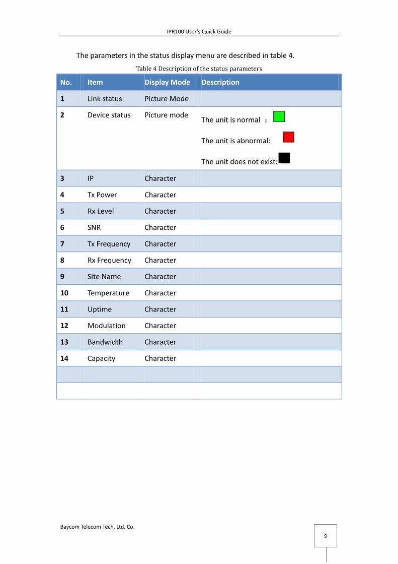
The parameters in the status display menu are described in table 4.
Table 4 Description of the status parameters
No. Item Display Mode Description
1 Link status Picture Mode
2 Device status Picture mode The unit is normal :
The unit is abnormal:
The unit does not exist:
3 IP Character
4 Tx Power Character
5 Rx Level Character
6 SNR Character
7 Tx Frequency Character
8 Rx Frequency Character
9 Site Name Character
10 Temperature Character
11 Uptime Character
12 Modulation Character
13 Bandwidth Character
14 Capacity Character

IPR100 User’s Quick Guide
Baycom Telecom Tech. Ltd. Co.
10
Step4-3Configuring RF Parameters for IPR100
RF parameters can be set in“Link Configuration->RF” menu as shown in
figure11.
Figure10RF Configuration
After input the parameters and click“set” button,the parameters will be
written into the local IPR100 device.
Before the microwave link is established, the operation will set the local device
only, once the link is established, the operation will set both the local device and the
remote device.
Table 5 RF Parameter description
No Parameter Item Remark
1 Tx Frequency According to the user’s
license
2 Tx Power
3 Tx Mute On:enable Tx Mute
Off: disable Tx Mute
Should be off when working
4 ATPC Disable: close ATPC function

IPR100 User’s Quick Guide
Baycom Telecom Tech. Ltd. Co.
11
Enable: start ATPC function
5 Max Rx Level XXX ATPC Range High
6 Min Rx Level XXX ATPC Range Low
Step4-5Configuring Modulation Parameters for IPR100
Modulation parameters can be set in “Link Configuration->Modem” menu as
shown in figer12.
Figure 11 Modulation Parameters Configuration Menu
After input the bandwidth and modulation parameters and click“Set” button,
the parameters will be written into local IPR100 device.
Before the microwave link is established, the operation will set the local device
only, once the link is established, the operation will set the local device as well as the
remote device.
Table 6Modulation Parameters
No Item Value Remark
1 Traffic Capacity Layer2 capacity, automatically
generated after user set the
bandwidth and modulation
2 Channel
Bandwidth
7/14/28/56 *1000Khz Depending on the user license

IPR100 User’s Quick Guide
Baycom Telecom Tech. Ltd. Co.
12
3 Modulation QPSK/16QAM/32QAM/6
4QAM128QAM/256QAM
/512QAM/1024QAM
Depending on the user license

IPR100 User’s Quick Guide
Baycom Telecom Tech. Ltd. Co.
13
Step4-5:Load User License
The IPR100 is initialized to 100MHz bandwidth and 128QAM modulation by
manufactory.
If the user has the new License file, he can down load the license by himself.
User License file can be down load in “Maintenance-> License” mane as shown
in figure 10.
Users enter the serial numbers and click the "Register" button to complete the
License file input.
Figure 12User’s License Management Menu

IPR100 User’s Quick Guide
Baycom Telecom Tech. Ltd. Co.
14
Step5:Adjust Antenna
Both ends of the IPR100 device must be configured with the same RF
parameters, modulation mode, ATPC mode and SYNC mode separately.
After setting the local IPR100 device, user must adjust the antenna height and
angle.
The RSSI feature is shown in figure 14. And the multi-meter will be used during
adjusting.
\
figure13RSSI V.S. RSL

IPR100 User’s Quick Guide
Baycom Telecom Tech. Ltd. Co.
15
Step6:Checking the Link status
After adjusting the antenna, the microwave communication link will be
established. Use may check the link status with WMT-IPR100 software.
Once the parameters of the remote IPR100 are displayed, the basic
configuration of the IPR100 is completed.
If the user want to configure other functions like QoS and VLAN, please refer to
“IPR100 Software Manual”.
IPR100 Package List
Table 7 IPR100 package list
No Equipment Number Remark
Host
1 IPR 1+0 all outdoor unit( fiber of GE) 1
Accessories
1 Waterproof glue 0.8 One Terminal
2 Polyethylene insulated wire 1.5mm2
BVR19/.41(Yellow-Green)
2 2m/One Terminal
3 Polyethylene insulated wire 1.5mm2
BVR19/.41(Red)
10 10m/One Terminal
4 Polyethylene insulated wir 1.5mm2
BVR19/.41(Black)
10 One Terminal
5 300mm Black Ties 200 One Terminal
6 150mm White Ties 100 One Terminal
7 IPR Ground Wire 1 One Terminal
8 2.5mm2 Copper Terminal 1 One Terminal
9 M5 X 8 Panel Screw 8 One Terminal
10 Black insulating tape 1 One Terminal