ipv catalog, high-pressure internal gear · pdf filevoith turbo ipv catalog high-pressure...
TRANSCRIPT

Voith Turbo
IPV catalogHigh-pressure internal gear pumps
Machines that run
Rarely seen, but hard at work in
countless machines, Voith Turbo
internal gear pumps reliably provide
high pressures. Their main applica-
tions are machines in the plastics
and sheet-metal processing sectors,
presses as well as conveying and
lifting equipment. These pumps are
also in demand for shipbuilding,
municipal vehicles, power plants
and special machine building.
Benefits that convince
Internal gear pumps from Voith Turbo
are working reliably in hundreds of
thousands of machines worldwide.
Sophisticated technology, robust
design and cost-efficient operation
have convinced thousands of cus-
tomers to trust Voith. Based on that
trust, we have become the world
market leader for high-pressure
internal gear pumps with gap com-
pensation.
Features that count
The market requires hydraulic
pumps that are quiet and compact
with minimal pressure pulsations
at simultaneously high efficiencies.
Voith Turbo has met these require-
ments with the IPV pumps, which
feature radial and axial sealing gap
compensation with volume-opti-
mized involute gearing.

Contents
Page
Design and function 3
Performance data 4
IPV 3 6
IPV 4 8
IPV 5 10
IPV 6 12
IPV 7 14
SAE suction and 16
pressure flanges
Type code 17
Order designation
Multi-flow pumps 18
Pump combinations
Designs 19
Die casting machine, pump with variable flow by speed control

Design and function
1 7 6 5 9 2 5 6 7 28 1 9 4a 4b 310
1 Pinion shaft2 Internal gear3 Filler pin
4a Filler segment carrier4b Filler sealing segment5 Axial disc6 Axial pressure area7 Plain bearings8 Housing9 Hydrostatic bearing
10 End cover with bleeder screw
Suction chamberPressure chamber
Design features
� Internal gear principle
� Sleeve bearing
� Radial and axial sealing gap
compensation
� Volume-optimized involute
gearing
Product characteristics
� Long life
� High volume efficiency
� High overall efficiency
� Very low pump flow and
pressure pulsation
� Low noise level
� Compact dimensions
� Low weight
� Large speed range
� Very good suction properties
� High allowed viscosity
� Simple maintenance
� Multiple pumps and pump
combinations are possible
� Suitable for variable-speed drives
(variable volume flow!)
� Motor operation possible
(energy recovery!)
Combinations
IPV pumps can be combined to
form dual or multi-flow pumps.
Combinations with other Voith Turbo
pump series are also possible. Used
in conjunction with pumps from the
medium and low-pressure series,
Voith equipment can handle a wide
range of potential applications.
For further information on possible
combinations, refer to page 9 and
brochure G1714 (Voith multi-flow
pumps).
Combinations with third-party prod-
ucts are generally possible. We'll be
happy to discuss your needs.
Variable volume flow
We supply complete hydraulic units
with IPV pumps, asynchronous
motors and frequency converters
(EPA/EPAF system) to generate
variable volume flows. For further
information, refer to our brochure
G1420 (Voith EPA system).
Function
Rotation of the gears within the
pump draws in the pressure fluid
(usually hydraulic oil) into the space
between the pinion and internal
gear. The two smooth running gears
help to ensure excellent intake
behaviour.
In the radial direction, the gear
chambers are closed by gear mesh-
ing and the filler piece. In the axial
direction, the axial plates seal the
pressure chamber with the minimal
possible gap. This design minimizes
volume losses and increases effi-
ciency.
When the gears rotate, the tooth
heads enter the gaps between teeth
and displace the pressure fluid.
2
3
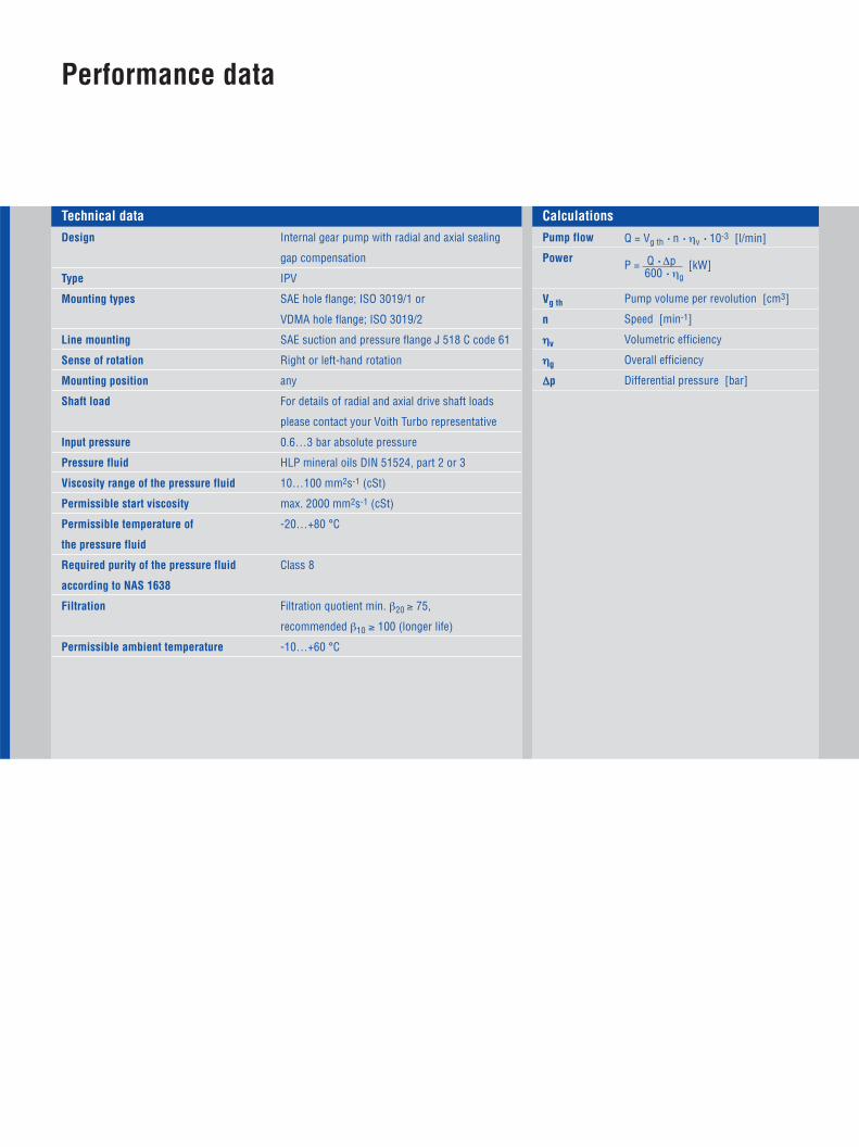
Design
Type
Mounting types
Line mounting
Sense of rotation
Mounting position
Shaft load
Input pressure
Pressure fluid
Viscosity range of the pressure fluid
Permissible start viscosity
Permissible temperature of
the pressure fluid
Required purity of the pressure fluid
according to NAS 1638
Filtration
Permissible ambient temperature
Internal gear pump with radial and axial sealing
gap compensation
IPV
SAE hole flange; ISO 3019/1 or
VDMA hole flange; ISO 3019/2
SAE suction and pressure flange J 518 C code 61
Right or left-hand rotation
any
For details of radial and axial drive shaft loads
please contact your Voith Turbo representative
0.6…3 bar absolute pressure
HLP mineral oils DIN 51524, part 2 or 3
10…100 mm2s-1 (cSt)
max. 2000 mm2s-1 (cSt)
-20…+80 °C
Class 8
Filtration quotient min. β20 ≥ 75,
recommended β10 ≥ 100 (longer life)
-10…+60 °C
Pump flow
Power
Vg th
n
ηv
ηg
∆p
Q = Vg th • n • ηv • 10-3 [l/min]
P = Q • ∆p [kW]600 • ηg
Pump volume per revolution [cm3]
Speed [min-1]
Volumetric efficiency
Overall efficiency
Differential pressure [bar]
Technical data Calculations
Performance data
4
5
Type, size-delivery
Displacement per revolution
[cm3]
max.
[min-1]
min.
[min-1]
Speed
at 1500 min-1
[l/min]
Delivery
Continuous
[bar]
Peak at1500 min-1
[bar]
Peak atnmax
[bar]
Pressures
IPV 3 – 3.5
IPV 3 – 5
IPV 3 – 6.3
IPV 3 – 8
IPV 3 – 10
IPV 4 – 13
IPV 4 – 16
IPV 4 – 20
IPV 4 – 25
IPV 4 – 32
IPV 5 – 32
IPV 5 – 40
IPV 5 – 50
IPV 5 – 64
IPV 6 – 64
IPV 6 – 80
IPV 6 – 100
IPV 6 – 125
IPV 7 – 125
IPV 7 – 160
IPV 7 – 200
IPV 7 – 250
3.6
5.2
6.4
8.2
10.2
13.3
15.8
20.7
25.4
32.6
33.1
41.0
50.3
64.9
64.1
80.7
101.3
126.2
125.8
160.8
202.7
251.7
5.4
7.8
9.6
12.3
15.3
19.9
23.7
31.0
38.1
48.9
49.6
61.5
75.4
97.3
96.1
121.0
151.9
189.3
188.7
241.2
304.0
377.5
330
330
330
330
330
330
330
330
300
250
315
315
280
230
300
280
250
210
300
280
250
210
345
345
345
345
345
345
345
345
330
280
345
345
315
250
330
315
300
250
330
315
300
250
345
345
345
345
345
345
345
345
330
280
315
315
280
250
300
280
270
250
300
280
270
250
400
400
400
400
400
400
400
400
400
400
400
400
400
400
400
400
400
400
400
400
400
400
3600
3600
3600
3600
3600
3600
3400
3200
3000
2800
3000
2800
2500
2200
2600
2400
2100
1800
2200
2000
1800
1800
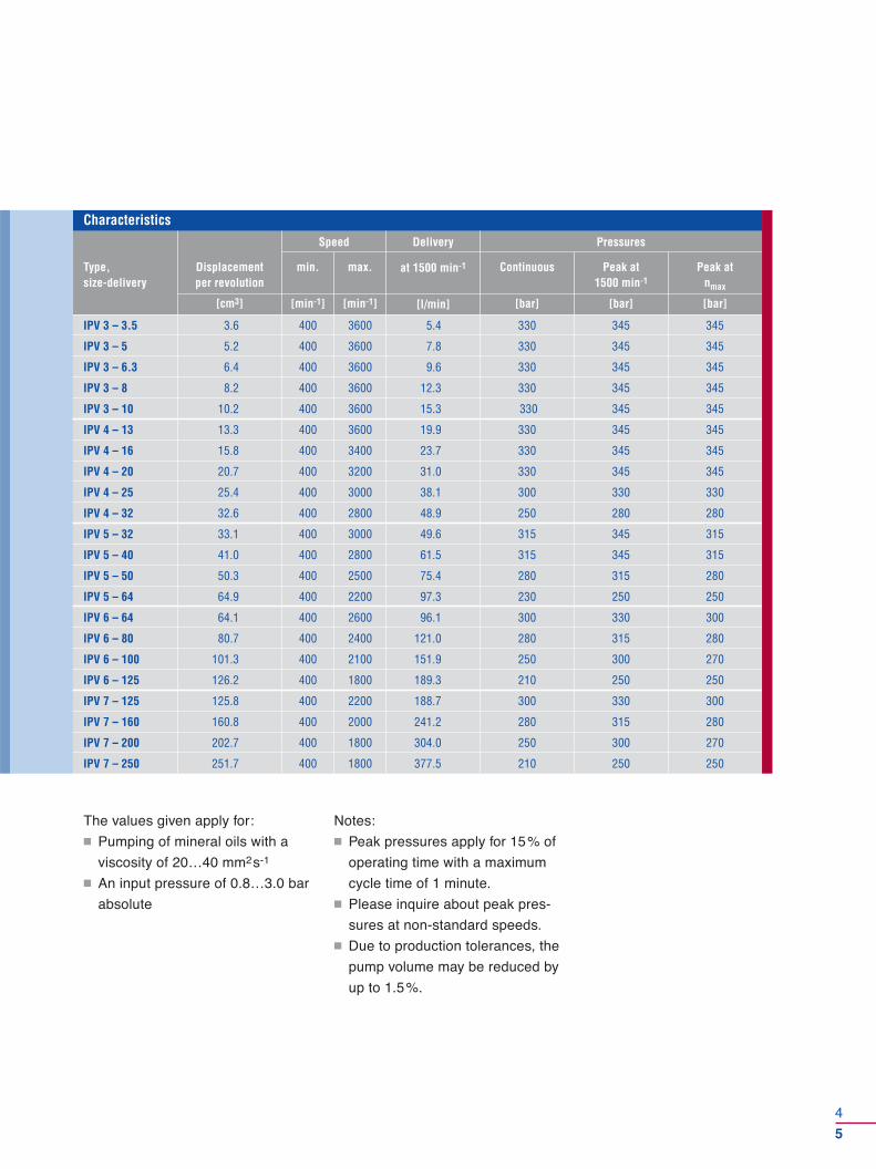
Characteristics
The values given apply for:
� Pumping of mineral oils with a
viscosity of 20…40 mm2s-1
� An input pressure of 0.8…3.0 bar
absolute
Notes:
� Peak pressures apply for 15% of
operating time with a maximum
cycle time of 1 minute.
� Please inquire about peak pres-
sures at non-standard speeds.
� Due to production tolerances, the
pump volume may be reduced by
up to 1.5%.
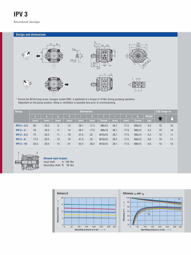
Standard design
IPV 3
70
100
0 50 150100 300 350200 250
75
80
85
90
95
Efficiency �v and �g
Effi
cien
cy in
%
Operating pressure p in bar
�v
�g
0
20
0 50 150100 300 350
5
10
15
200 250
Delivery Q
Del
iver
y Q
in l/
min
Operating pressure p in bar
A B
Allowed input torques:Input shaft A: 160 NmSecondary shaft B: 80 Nm
Design and dimensions
* Ensure the M10x1plug screw, hexagon socket SW5, is tightened to a torque of 10 Nm during pumping operation.Dependent on the pump position, filling or ventilation is possible here prior to commissioning.
c e g h i k l r v w
IPV 3 – 3.5 66 20.5 9 14 38.1 17.5 M8x13 38.1 17.5 M8x13 4.0 10 10
IPV 3 – 5 70 20.5 11 14 38.1 17.5 M8x13 38.1 17.5 M8x13 4.2 10 10
IPV 3 – 6.3 73 20.5 11 19 47.5 22 M10x15 38.1 17.5 M8x13 4.4 10 11
IPV 3 – 8 77.5 20.5 13 19 47.5 22 M10x15 38.1 17.5 M8x13 4.6 10 11
IPV 3 – 10 82.5 20.5 13 21 52.4 26.2 M10x15 38.1 17.5 M8x13 4.8 10 12
ø18 h7
20.5
6 h9
c e
ø82.5
5 h8
11
132 106.4
M5
19.5
12 6
43 35
c/2 c/2
5.8 v
r
w g *
*
*
k
hl
i
435153
47
SAE flange no.
Weight
[mm] [mm] [mm] [mm] [mm] [mm] Thread [mm] [mm] Thread [kg]
DimensionsDesign

6
7
Pump sizes Rotation, suction connectionType Mounting flange Shaft end
3.5
5
6.3
8
10
IPV 3
Designation according to type code Type code/order designation, see page 17
0
10
0 50 150100 300 350200 250
2
4
6
8
Input power P
Operating pressure p in bar
Inpu
t P in
kW
40
60
0 50 150100 300 350
45
50
55
200 250
Airborne noise level Measuring location 1 m axial
Operating pressure p in bar
Airb
orne
noi
se le
vel i
n dB
(A)
Measurement conditions:Speed: 1500 min-1
Viscosity of pressure fluid: 46 mm2s-1
Operating temperature: 40 °C
Characteristic curves:IPV 3 – 3.5IPV 3 – 5IPV 3 – 6.3IPV 3 – 8IPV 3 – 10
Note: Measurement taken in a low-noise room.In a anechoic room, the measurements are approx. 5 dB(A) lower.
Clockwise rotation, radial suction port
1
SAE 2-hole flange, dimensions on left
0
Parallel shaft with keyway connection,dimensions on left
1
Anti-clockwise rotation, radial suction port
6
VDMA 2-hole flange
12
7
36
ø80
h8
109
13219.5
11
4
Involute gearing with 2-hole SAE flange
37.9
30
ANSI B92.1a 11 T16/32 DP 30°
0
36
ø16 h7
5 h9
18
28 1
Standard
Variants
43 19.5
35
43
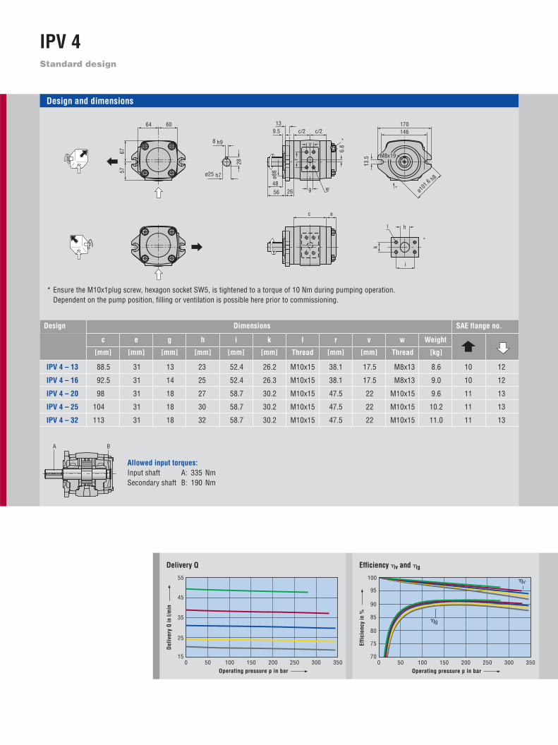
Standard design
IPV 4
70
100
0 50 150100 300 350200 250
75
80
85
90
95
Efficiency �v and �g
Effi
cien
cy in
%
Operating pressure p in bar
�v
�g
15
55
0 50 150100 300 350
25
35
45
200 250
Delivery Q
Del
iver
y Q
in l/
min
Operating pressure p in bar
Allowed input torques:Input shaft A: 335 NmSecondary shaft B: 190 Nm
Design and dimensions
* Ensure the M10x1plug screw, hexagon socket SW5, is tightened to a torque of 10 Nm during pumping operation.Dependent on the pump position, filling or ventilation is possible here prior to commissioning.
SAE flange no.
Weightc e g h i k l r v w
[mm] [mm] [mm] [mm] [mm] [mm] Thread [mm] [mm] Thread [kg]
IPV 4 – 13 88.5 31 13 23 52.4 26.2 M10x15 38.1 17.5 M8x13 8.6 10 12
IPV 4 – 16 92.5 31 14 25 52.4 26.3 M10x15 38.1 17.5 M8x13 9.0 10 12
IPV 4 – 20 98 31 18 27 58.7 30.2 M10x15 47.5 22 M10x15 9.6 11 13
IPV 4 – 25 104 31 18 30 58.7 30.2 M10x15 47.5 22 M10x15 10.2 11 13
IPV 4 – 32 113 31 18 32 58.7 30.2 M10x15 47.5 22 M10x15 11.0 11 13
DimensionsDesign
6757
6064
8 h9
28
ø25 h7
k
hl
i
13.
5
170
ø101
.6 h8
M8x19
146
c e
26
9.5 13
56
c/2 c/2
48
6.8
v
r
g w
ø88
*
*
*
A B

38
45.9
48
5656
26
32
48
32
126
ø101
.6 h
8
ø78
9013.5
12450
124
90
52.5
42
52.5
129
ø100
h8
11
124ø125
50
8
9
13
16
20
25
32
IPV 4
Designation according to type code Type code/order designation, see page 17
0
25
0 50 150100 300 350200 250
5
10
15
20
Input power P
Operating pressure p in bar
Inpu
t P in
kW
40
60
0 50 150100 300 350
45
50
55
200 250
Airborne noise level Measuring location 1 m axial
Operating pressure p in bar
Airb
orne
noi
se le
vel i
n dB
(A)
Measurement conditions:Speed: 1500 min-1
Viscosity of pressure fluid: 46 mm2s-1
Operating temperature: 40 °C
Characteristic curves:IPV 4 – 13IPV 4 – 16IPV 4 – 20IPV 4 – 25IPV 4 – 32
Note: Measurement taken in a low-noise room.In a anechoic room, the measurements are approx. 5 dB(A) lower.
Clockwise rotation, radial suction port
1
SAE 2-hole flange, dimensions on left
7
Parallel shaft with keyway connection,dimensions on left
1
Anti-clockwise rotation, radial suction port
6
SAE 4-hole flange
VDMA 4-hole flange
1
5
Involute gearing with 2-hole SAE flange
ANSI B92.1a 15 T16/32 DP 30°
0
1
1
Pump sizes Rotation, suction connectionType Mounting flange Shaft endStandard
Variants
Standard design
IPV 5
70
100
0 50 150100 300 350200 250
75
80
85
90
95
Efficiency �v and �g
Effi
cien
cy in
%
Operating pressure p in bar
�v
�g
40
100
0 50 150100 300 350
60
70
80
200 250
50
90
Delivery Q
Del
iver
y Q
in l/
min
Operating pressure p in bar
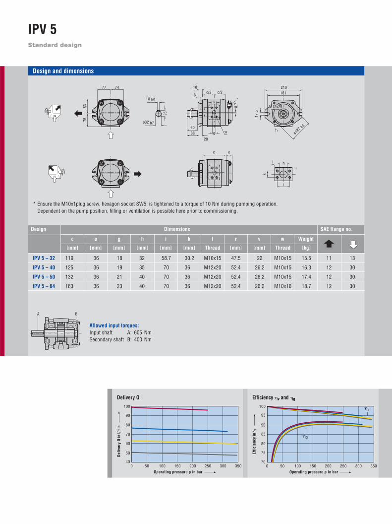
Allowed input torques:Input shaft A: 605 NmSecondary shaft B: 400 Nm
Design and dimensions
* Ensure the M10x1plug screw, hexagon socket SW5, is tightened to a torque of 10 Nm during pumping operation.Dependent on the pump position, filling or ventilation is possible here prior to commissioning.
SAE flange no.
Weightc e g h i k l r v w
[mm] [mm] [mm] [mm] [mm] [mm] Thread [mm] [mm] Thread [kg]
IPV 5 – 32 119 36 18 32 58.7 30.2 M10x15 47.5 22 M10x15 15.5 11 13
IPV 5 – 40 125 36 19 35 70 36 M12x20 52.4 26.2 M10x15 16.3 12 30
IPV 5 – 50 132 36 21 40 70 36 M12x20 52.4 26.2 M10x15 17.4 12 30
IPV 5 – 64 163 36 23 40 70 36 M12x20 52.4 26.2 M10x16 18.7 12 30
DimensionsDesign
k
hl
i
20
6
18
68
c/2
c
c/2
60
8.7
v
r
g w
e
8375
7477
ø32 h7
*
*
*
17.
5
210
ø127 h8
M12x25
18110 h9
35
A B

10
11
60
68
20
68
20
55,4
47,5
55,4
146
13,5
13
172
ø101
,6 h
8
35
60ø162
ø190
17,5
166
35
ca. ø
100
ø127
h8
53
68,5
58ø160
ø190
14
68,5
169
ø125
h8
53
32
40
50
64
IPV 5
Designation according to type code Type code/order designation, see page 17
0
50
0 50 150100 300 350200 250
10
20
30
40
Input power P
Operating pressure p in bar
Inpu
t P in
kW
50
70
0 50 150100 300 350
55
60
65
200 250
Airborne noise level Measuring location 1 m axial
Operating pressure p in bar
Airb
orne
noi
se le
vel i
n dB
(A)
Measurement conditions:Speed: 1500 min-1
Viscosity of pressure fluid: 46 mm2s-1
Operating temperature: 40 °C
Characteristic curves:IPV 5 – 32IPV 5 – 40IPV 5 – 50IPV 5 – 64
Note: Measurement taken in a low-noise room.In a anechoic room, the measurements are approx. 5 dB(A) lower.
Clockwise rotation, radial suction port
1
SAE 2-hole flange, dimensions on left
0
Parallel shaft with keyway connection,dimensions on left
1
Anti-clockwise rotation, radial suction port
6
SAE 2-hole flange, variant
SAE 4-hole flange
VDMA 4-hole flange
7
1
5
Involute gearing
ANSI B92.1a 14 T12/24 DP 30°
0
1
1
Pump sizes Rotation, suction connectionType Mounting flange Shaft endStandard
Variants

Standard design
IPV 6
70
100
0 50 150100 300 350200 250
75
80
85
90
95
Efficiency �v and �g
Effi
cien
cy in
%
Operating pressure p in bar
�v
�g
75
200
0 50 150100 300 350
125
150
175
200 250
100
Delivery Q
Del
iver
y Q
in l/
min
Operating pressure p in bar
Allowed input torques:Input shaft A: 1050 NmSecondary shaft B: 780 Nm
Design and dimensions
* Ensure the M10x1plug screw, hexagon socket SW5, is tightened to a torque of 10 Nm during pumping operation.Dependent on the pump position, filling or ventilation is possible here prior to commissioning.
SAE flange no.
Weightc e g h i k l r v w
[mm] [mm] [mm] [mm] [mm] [mm] Thread [mm] [mm] Thread [kg]
IPV 6 – 64 140 40 23 40 70 36 M12x20 52.4 26.2 M10x15 29.2 12 30
IPV 6 – 80 148 35 23 45 77.8 42.9 M12x20 70 36 M12x20 30.7 14 15
IPV 6 – 100 158 35 27 50 77.8 42.9 M12x20 70 36 M12x20 32.6 14 15
IPV 6 – 125 170 40 30 50 77.8 42.9 M12x20 70 36 M12x20 35.0 14 15
DimensionsDesign
20
6
22
c/2
11,
2
g w
e
c/2
c
88 80
v
r
*
k
hl
i
264228.6
22
ø152
.4 h8
M12x25
12 h9
43
ø40 h7
109
9598100
*
*
A B

12
13
88
80 22
88
181
17.5
210
54
61.9
18
61.9
ø127
h8
22
264
ø228.6
22
51
80
51
206
ø152
.4 h
8
ca.ø
120
59
92.5
82ø200
ø240
18ø160
h8
189
92.5 59
64
80
100
125
IPV 6
Designation according to type code Type code/order designation, see page 17
0
100
0 50 150100 300 350200 250
20
40
60
80
Input power P
Operating pressure p in bar
Inpu
t P in
kW
55
75
0 50 150100 300 350
60
65
70
200 250
Airborne noise level Measuring location 1 m axial
Operating pressure p in bar
Airb
orne
noi
se le
vel i
n dB
(A)
Measurement conditions:Speed: 1500 min-1
Viscosity of pressure fluid: 46 mm2s-1
Operating temperature: 40 °C
Characteristic curves:IPV 6 – 64IPV 6 – 80IPV 6 – 100IPV 6 – 125
Note: Measurement taken in a low-noise room.In a anechoic room, the measurements are approx. 5 dB(A) lower.
Clockwise rotation, radial suction port
1
SAE 2-hole flange, dimensions on left
0
Parallel shaft with keyway connection,dimensions on left
1
Anti-clockwise rotation, radial suction port
6
SAE 2-hole flange, variant
SAE 4-hole flange
VDMA 4-hole flange
7
1
5
Involute gearing
ANSI B92.1a 17 T12/24 DP 30°
0
1
1
Pump sizes Rotation, suction connectionType Mounting flange Shaft endStandard
Variants
Standard design
IPV 7
70
100
0 50 150100 300 350200 250
75
80
85
90
95
Efficiency �v and �g
Effi
cien
cy in
%
Operating pressure p in bar
�v
�g
150
400
0 50 150100 300 350
250
300
350
200 250
200
Delivery Q
Del
iver
y Q
in l/
min
Operating pressure p in bar
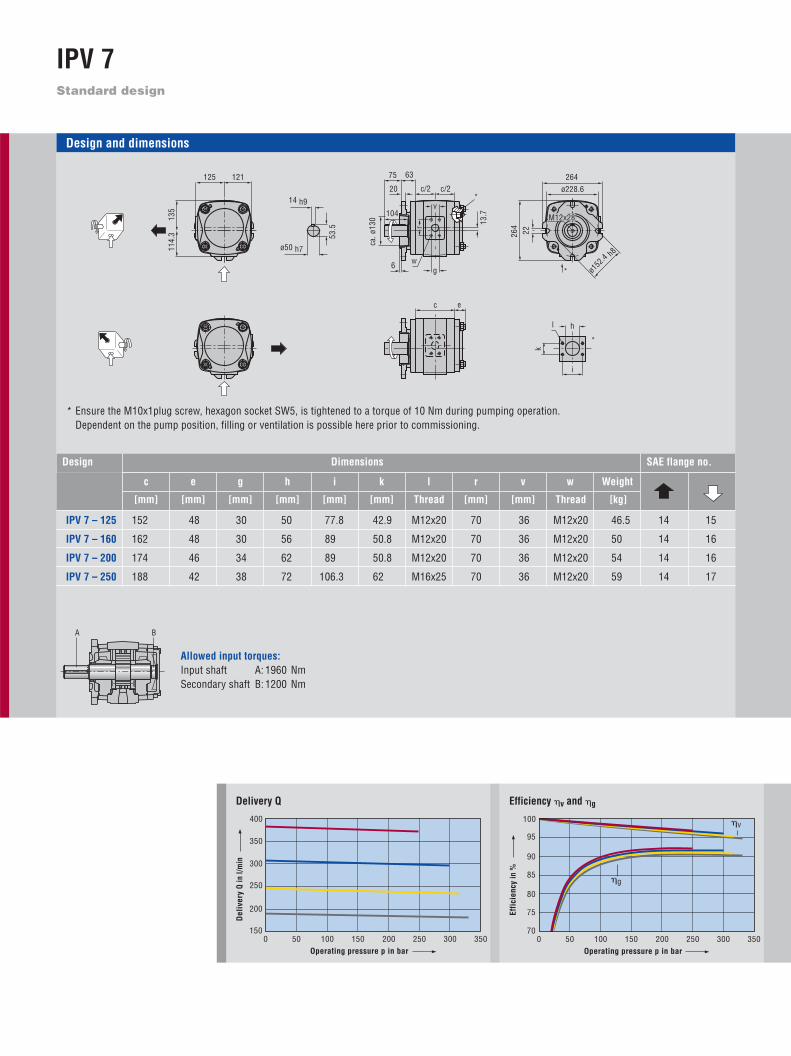
Allowed input torques:Input shaft A: 1960 NmSecondary shaft B: 1200 Nm
Design and dimensions
* Ensure the M10x1plug screw, hexagon socket SW5, is tightened to a torque of 10 Nm during pumping operation.Dependent on the pump position, filling or ventilation is possible here prior to commissioning.
SAE flange no.
Weightc e g h i k l r v w
[mm] [mm] [mm] [mm] [mm] [mm] Thread [mm] [mm] Thread [kg]
IPV 7 – 125 152 48 30 50 77.8 42.9 M12x20 70 36 M12x20 46.5 14 15
IPV 7 – 160 162 48 30 56 89 50.8 M12x20 70 36 M12x20 50 14 16
IPV 7 – 200 174 46 34 62 89 50.8 M12x20 70 36 M12x20 54 14 16
IPV 7 – 250 188 42 38 72 106.3 62 M16x25 70 36 M12x20 59 14 17
DimensionsDesign
135
114.
3121125 264
ø228.6
22
ø152
.4 h8
M12x28
264
k
hl
i
ø50 h7
14 h9
53.
5
20
6
63
c/2
13.
7
gw
e
c/2
c
75
104v
r
ca. ø
130
*
*
*
A B
14
15
75
104
7563
87.3 63
120.5
110
ø200
h8
209
120.5 63
ø250
ø290
22
125
160
200
250
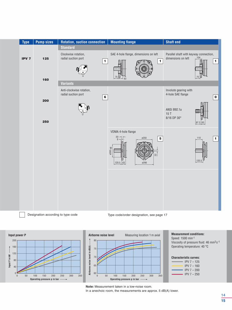
IPV 7
Designation according to type code Type code/order designation, see page 17
0
200
0 50 150100 300 350200 250
40
80
120
160
Input power P
Operating pressure p in bar
Inpu
t P in
kW
60
80
0 50 150100 300 350
65
70
75
200 250
Airborne noise level Measuring location 1 m axial
Operating pressure p in bar
Airb
orne
noi
se le
vel i
n dB
(A)
Measurement conditions:Speed: 1500 min-1
Viscosity of pressure fluid: 46 mm2s-1
Operating temperature: 40 °C
Characteristic curves:IPV 7 – 125IPV 7 – 160IPV 7 – 200IPV 7 – 250
Note: Measurement taken in a low-noise room.In a anechoic room, the measurements are approx. 5 dB(A) lower.
Clockwise rotation, radial suction port
1
SAE 4-hole flange, dimensions on left
1
Parallel shaft with keyway connection,dimensions on left
1
Anti-clockwise rotation, radial suction port
6
VDMA 4-hole flange
5
Involute gearing with 4-hole SAE flange
ANSI B92.1a 15 T8/16 DP 30°
0
1
Pump sizes Rotation, suction connectionType Mounting flange Shaft endStandard
Variants

k
ic
BD
A
1)
2)
according to SAE J 518 C code 61
SAE suction and pressure flanges
1) Round seal ring (O-ring) ISO-R 1629 NBR2) Machine screw EN ISO 47623) Special design, deviating from SAE J 518 C code 61
SAE flange, single-piece
SAE flange no. A B C D E1) i k S2) max. pressure
Thread [mm] [mm] [mm] Seal ring [mm] [mm] Thread [bar]
10 G 1/2 46 54 36 18.66 – 3.53 38.1 17.5 M 8 345
11 G 3/4 50 65 36 24.99 – 3.53 47.6 22.2 M 10 345
12 G 1 55 70 38 32.92 – 3.53 52.4 26.2 M 10 345
13 G 1-1/4 68 79 41 37.69 – 3.53 58.7 30.2 M 10 276
143) G 1-1/2 82 98 50 47.22 – 3.53 70 36 M 12 3453)
30 G 1-1/2 78 93 45 47.22 – 3.53 70 36 M 12 207
15 G 2 90 102 45 56.74 – 3.53 77.8 42.9 M 12 207
16 G 2-1/2 105 114 50 69.44 – 3.53 89 50.8 M 12 172
17 G 3 124 134 50 85.32 – 3.53 106.3 62 M 16 138
18 G 4 146 162 48 110.72 – 3.53 130 77.8 M 16 34
16
17
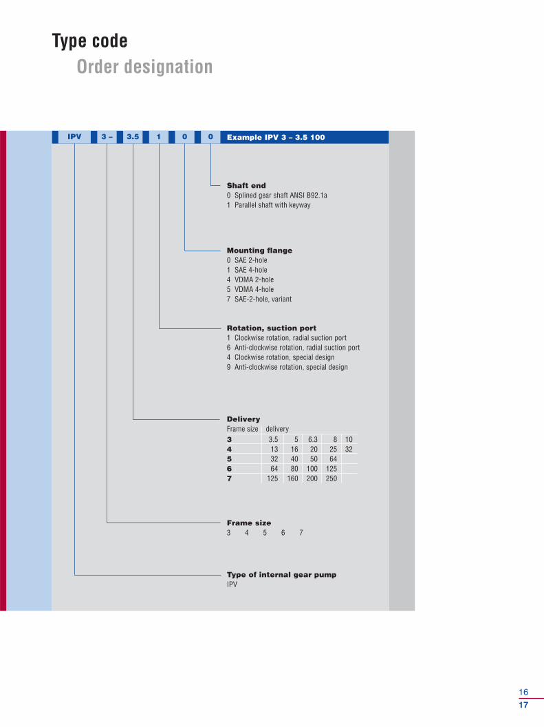
Type codeOrder designation
IPV 3 – 3.5 1 0 0
Type of internal gear pumpIPV
Shaft end0 Splined gear shaft ANSI B92.1a1 Parallel shaft with keyway
Frame size3 4 5 6 7
Rotation, suction port1 Clockwise rotation, radial suction port6 Anti-clockwise rotation, radial suction port4 Clockwise rotation, special design9 Anti-clockwise rotation, special design
Mounting flange0 SAE 2-hole1 SAE 4-hole4 VDMA 2-hole5 VDMA 4-hole7 SAE-2-hole, variant
Example IPV 3 – 3.5 100
DeliveryFrame size delivery3 3.5 5 6.3 8 104 13 16 20 25 325 32 40 50 646 64 80 100 1257 125 160 200 250
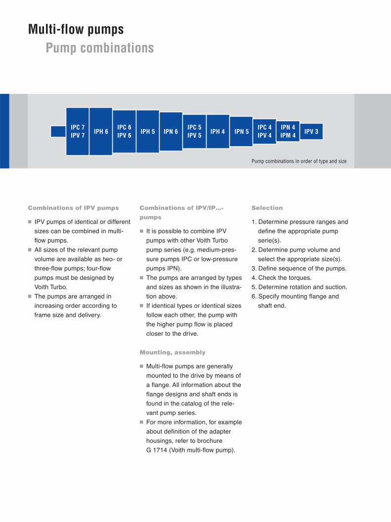
IPC 7IPV 7
IPC 6IPV 6 IPN 6
IPC 5IPV 5 IPH 4 IPN 5
IPC 4IPV 4
IPN 4IPM 4 IPV 3IPH 6 IPH 5
Multi-flow pumpsPump combinations
Combinations of IPV pumps
� IPV pumps of identical or different
sizes can be combined in multi-
flow pumps.
� All sizes of the relevant pump
volume are available as two- or
three-flow pumps; four-flow
pumps must be designed by
Voith Turbo.
� The pumps are arranged in
increasing order according to
frame size and delivery.
Selection
1. Determine pressure ranges and
define the appropriate pump
serie(s).
2. Determine pump volume and
select the appropriate size(s).
3. Define sequence of the pumps.
4. Check the torques.
5. Determine rotation and suction.
6. Specify mounting flange and
shaft end.
Combinations of IPV/IP…-
pumps
� It is possible to combine IPV
pumps with other Voith Turbo
pump series (e.g. medium-pres-
sure pumps IPC or low-pressure
pumps IPN).
� The pumps are arranged by types
and sizes as shown in the illustra-
tion above.
� If identical types or identical sizes
follow each other, the pump with
the higher pump flow is placed
closer to the drive.
Mounting, assembly
� Multi-flow pumps are generally
mounted to the drive by means of
a flange. All information about the
flange designs and shaft ends is
found in the catalog of the rele-
vant pump series.
� For more information, for example
about definition of the adapter
housings, refer to brochure
G 1714 (Voith multi-flow pump).
Pump combinations in order of type and size
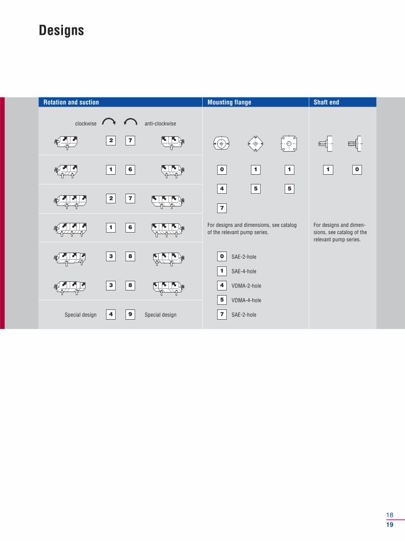
Rotation and suction Mounting flange Shaft end
18
19
Designs
Special design Special design
clockwise anti-clockwise
For designs and dimensions, see catalogof the relevant pump series.
For designs and dimen-sions, see catalog of therelevant pump series.
2
1
2
1
3
3
7
6 0 1 1 1 0
4 5 5
7
0
1
4
5
7
7
6
8
8
4 9
SAE-2-hole
SAE-4-hole
VDMA-2-hole
VDMA-4-hole
SAE-2-hole
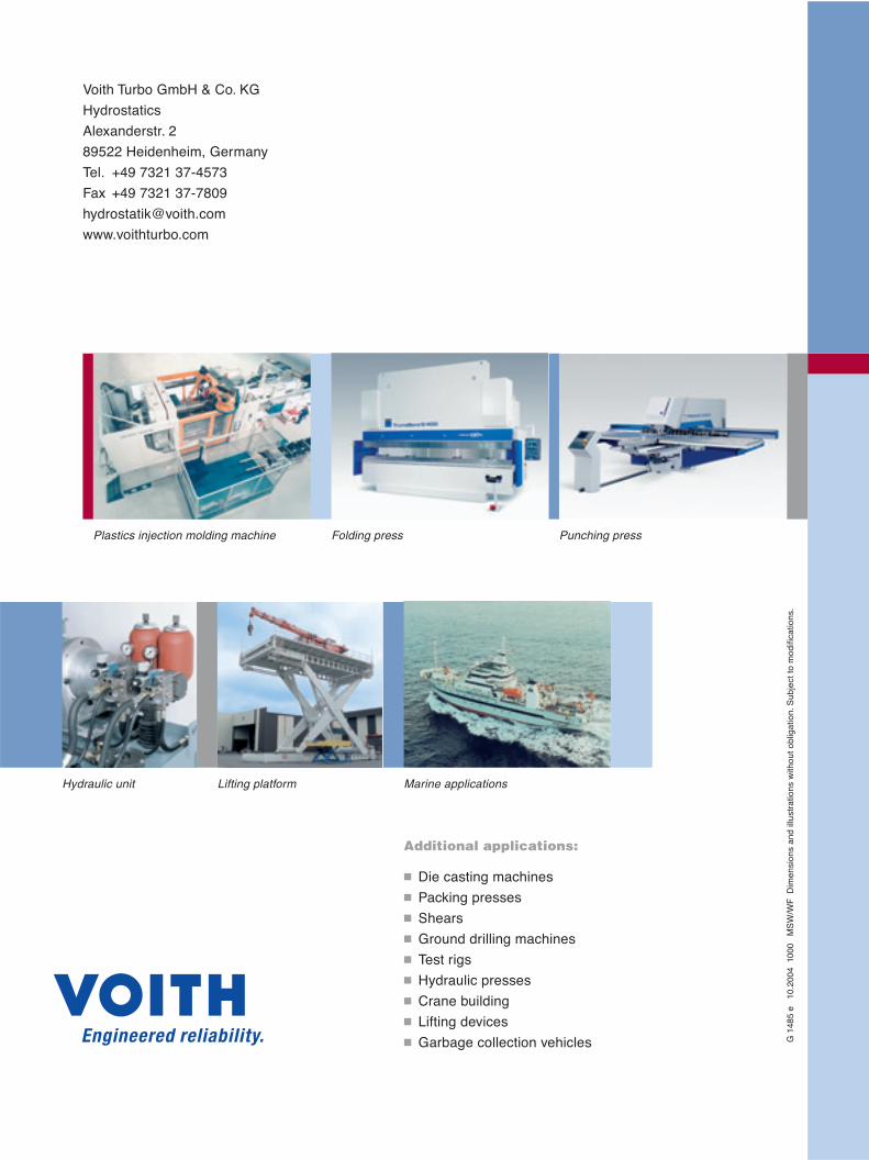
Voith Turbo GmbH & Co. KG
Hydrostatics
Alexanderstr. 2
89522 Heidenheim, Germany
Tel. +49 7321 37-4573
Fax +49 7321 37-7809
www.voithturbo.com
G 1
485
e 1
0.20
04 1
000
MS
W/W
F D
imen
sion
s an
d ill
ustr
atio
ns w
ithou
t obl
igat
ion.
Sub
ject
to m
odifi
catio
ns.
Plastics injection molding machine Folding press Punching press
Hydraulic unit Lifting platform Marine applications
Additional applications:
� Die casting machines
� Packing presses
� Shears
� Ground drilling machines
� Test rigs
� Hydraulic presses
� Crane building
� Lifting devices
� Garbage collection vehicles