irc sp 84-2009
DESCRIPTION
Manual for four laning of highwaysTRANSCRIPT
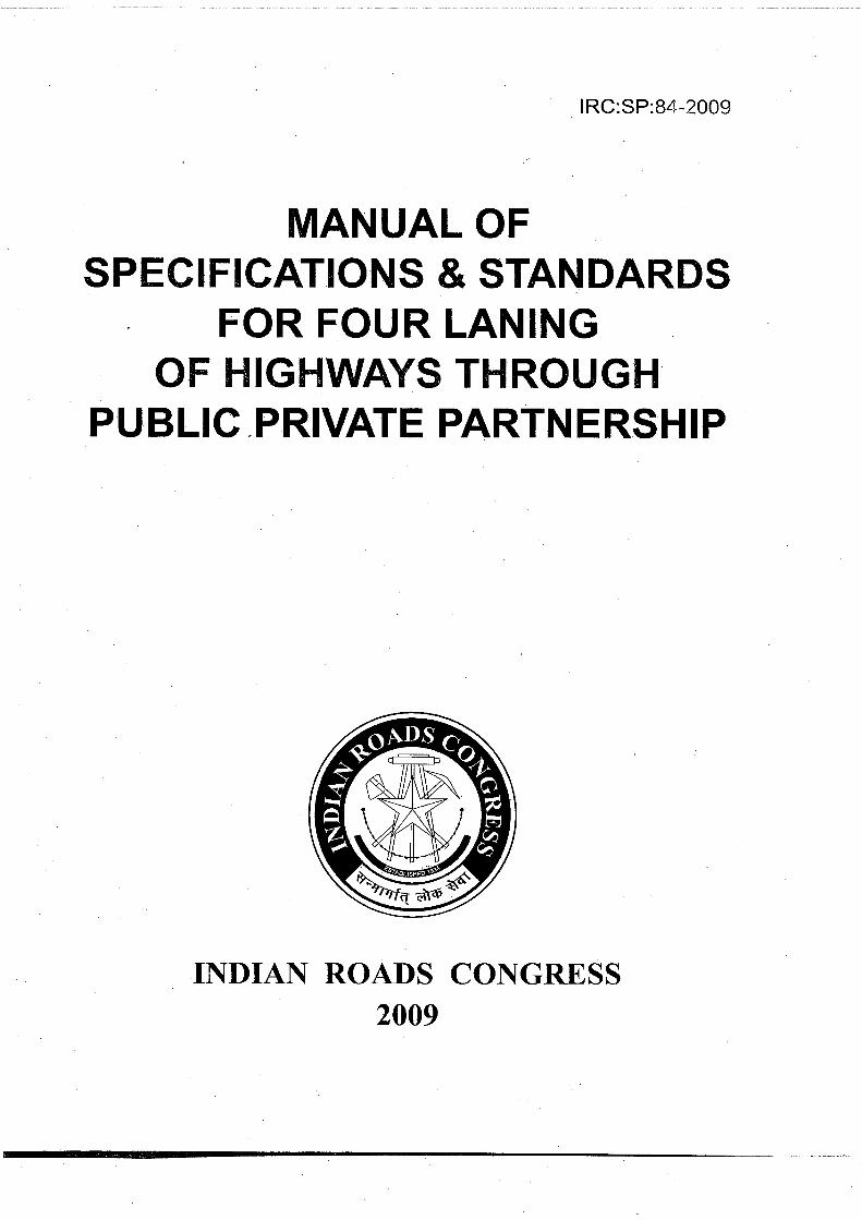
IRC:SP:84-2009
MANUAL OFSPECIFICATIONS & STANDARDS
FOR FOUR LANINGOF HIGHWAYS TþI ROUGH
PU BLIC PRIVATE PARTN ERSHIP
II{DIAN ROADS CONGRESS2009


MANUALOFS PËCI FIGATIONS & STAN DARDS
FOR FOUR LANINGOF HIGHWAYSTHROUGH
PI.J BLIT PRIVATE PARTN ERSH I P
Published by
INDIAN ROADS CONGRESSKama Koti Marg,
Sector6, R K. Puram,New Delhi-110 022
2009
IRC:SP:84-2009
Price Rs. 1000(Packing and Postage charges extra)


IRC:SP:84-2009
Published in October, 2009
(The Rights of Publication and Translation are reserved)
Printed at lndia Offset Press, New Delhi-110 064(500 copies)


Sl. No.
1.
2.
3
4.
5
6
7
B
I10
11
12
13
CONTENTS
Particulars
Personnelof the General Specifications and StandardsCommittee
General
Geometric Design and General Features
I ntersections and Grade Separators
Embankment and Cut Sections
Pavement Design
Highway Drainage
Design of Structures
Materials
Traffic Control Devices/Road Safety Devices/Road Side Furniture
TollPlazas
Landscaping and Tree Plantation
Project Facilities
Special Requirements for Hill Roads
Appendix -1
Appendix -2
IRC:SP:84-2009
Page No.
V
1
I
35
39
45
55
63
B1
89
111
123
129
145
151
154


IRC:SP:84-2009
PERSONNEL OF THE GENERAL SPECIFICATIONSAND STANDARDS COMMTTTEE (cSS)
(1Otn June, 2009)
1.
2.
3.
ShriV.K. Sinha(Convenor)
Shri Nirmaljit Singh(Co-Convenor)
ShriC. Kandasamy(Member-Secretary)
4. Shri R. D. Ram
ShriShailendra Kumar
Shri H.S. Chahal
9.
L
7.
Shri H. D. Vala
Prof. S. S. Chakraborty
Shri P. K. Datta
TheAddl. Director General - l, Ministry of Shipping,Road Transport & Highways, Deptt. of Road Tpt &Highways, Transport Bhavan, New Delhi- 110 001
TheAddl. Director General- ll, Ministry of Shipping,Road Transport & Highways, Deptt. of Road Tpt &Highways, Transport Bhavan, New Delhi - 110 001
The Chief Engineer (R) (S & R), Ministry ofShipping, Road Transporl and Highways,Transport Bhavan, New Delhi- 110 001
Members
Eng ineer-in-Ch ief-cum-Addl. Comm. -cu m-Spl.Secretary Rural Construction Deptt.,Vishweshwaraiya Bhawan Campus,Patna - 800 015
Chief Engineer (NH), M.P. P.W.D.,Satpura Bhawan, 1st Floor, Bhopal - 462 003
Vice Chancellor, Deenbandhu ChotturamUniversity of Science & Technology,Murthal, Sonipat
Managing Director, Consulting Engg. Services (l)Pvt. Ltd.,57, Nehru Place, New Delhi- 110 O1g
Executive Director, Consulting Engg. Services (l)Pvt. Ltd., 57, Nehru Place,Sth FloorNew Delhi - 110 016
Chief Engineer (R & B) Deptt., Govt. of Gujarat,Block No-1 4, New Sachivalaya,Gandhinagar - 382 010
Chief Engineer, Ministryof Shipping, RoadTransport & Highways, Transport Bhavan,New Delhi - 110 001
DG (RD) &AS, MOST (Retd.)D-21, Greater Kailash Part-l Enclave,New Delhi - 110 048
5.
6.
10. Shri A. N. Dhodapkar
11. Shri D. P. Gupta

IRC:SP:84-2009
12. ShriVishwas -Jain Managing Director, Consulting Engineers Group
Ltd., E-12, MojiColony, Malviya Nagar, Jaipur
13. ShriA. C. Bordoloi Chief Engineer (N. H. Works), Assam, Chandmari,Guwahati -781013
14. Shri D. G. Marathe Chief Engineer, Nasik Public Works Region,
Trimbak Road, Nasik - 422002
15. Shri Pinaki Roy Managing Director, LeaAssociates (SA)Pvt. Ltd.
choudhury B-11827, Mohyan co-op. lndustrial Estate,
Mathura Road New Delhi - 110 044
16. Shri A. D. Narain DG (RD) & AS MOST (Retd.), B-186, Sector-26,Noida - 201 301
17. Shri Arun Kumar Engineer-in-chief, H. P. PWD, U. S. Club,
Mahajan Shimla - 171 001
19. shri B. c. Pradhan chief Engineer (NH), Sachivalya Marg,Unit-lV Bhubaneshwar - 7 51 001 Orissa
1g. Shri S. K. Puri Member(Technical), NationalHighwaysAuthorityoflndia, Plot No. G - 5 & 6, Dwarka, Sector 10,
New Delhi- 110 075
20. Shri K. B. Rajoria Engineer-in-chief, Delhi PWD (Retd.), B-25,
Greater Kailash Part ll Enclave, New Delhi - 110 048
21. ShriV. Ravindranath Chief Engineer (R & B) & Managing Director,
APRDC, Room No.207, NH Building, Errummanzil,Hyderabad - 500 082
22. Shris. N. Das chief Engineer(Mech.), Ministryof shipping,Road Transport & Highways, Transport Bhawan,New Delhi - 110 001
23. Shri Ramesh Chandra Chief Engineer (Rohini), Delhi DevelopmentAuthority, Sector-3, Near Deepali Chowk, Rohini,Delhi - 110 085
24. Shri Rama Shankar Past Secretary General, lRC, C-47B,ll Floor,
Sharma Vikas Puri, New Delhi - 110 018
25. Shri N. K. Sharma Chief Engineer, National Highways,Rajasthan PWD, JaiPur - 302 006
26. Shri K. B. Lalsinghal E-in-C Haryana PWD (Retd.), House No. 684,
iector 16, Panchkula - 134 109 (Haryana)
vi

27. Dr. M. G. Tamhankar
28. Shri P. S. Tyagi
Maj. V. C. Verma29.
30. ShriGhasi Ram
32.
Col. O. P. Shrivastava
ShriKrishna Kumar
Dr. B. C. Roy33.
34. Prof Mahesh Tandon
Shri D. D. Sharma
ShriAnil Banchor
37. Col. A. K. Bhasin
38. ShriAshok Kumar
IRC:SP:84-2009
Director - Grade Scientist (SERC-G) (Retd.) &Former Emeritus Scientist (CSIR), BH-1144,Kendriya Vihar, Sector-11 , Kharghar,Navi Mumbai - 410210
Flat No. A-201, Vasundra ValleyApartment, GH-3,Sector Vl, Vasundra, Distt. Ghaziabad-1 0
Executive Di rector-Marketi n g, Orienta I Structu ralEngrs. Pvt. Ltd.,21, Commercial Complex,Malcha Marg, Diplomatic Encl.New Delhi - 110 021
Deputy Director General (D & S), HQ DGBR,Seema Sadak Bhavan, Ring Road, Naraina,Delhi Cant., New Delhi- 110 010
Director (Design), E-in-C Branch, Kashmir House,P. O.AHQ, Rajaji Marg, New Delhi- 110 011
Chief Engineer, UP PWD, 96, M. G. Marg,Lucknow -226OO1
Executive Director, Consulting Engg. Services (l)Pvt. Ltd.,57, Nehru Place,Sth Floor,New Delhi- 110 019
Managing Director,Tandon Consultants (P) Ltd., 17, Link Road,Jangpura Extn., New Delhi - 110 014
l-1603, Chittaranjan Park, New Delhi- 1',l0 019
Head - Business Expansion, ACC ConcreteLimited, Leela Business Park.3rd Floor,Opp. Hotel Leela, Andheri Kurla Road,Andheri (East) Mumbai - 400 059
Senior Joint Presídent, M/s Jaypee Gangalnfrastructure Corpn. Ltd., Sector-128,Noida-201 304
Chief Engineer, Ministry of Shipping, RoadTransport & Highways, Transport Bhawan,New Delhi - 110 001
31.
35.
36.
vii

-..,, :,,,Jr :,i.,*'.,,,*;i¿¡.,¿s;"*+-.:-*'
IRC:SP:84-2009
Ex-Officio Members
1 Shri D. B. Deshpande (President, IRC) Secretary to the Govt. ofMaharashtra, SachivalaYa, Mumbai
2. The Director General Ministry of Shipping, Road Transport & Highways,
(Road Devqlopment) & Transport Bhawan, New Delhi- 110 001
Special Secretary to theGovt. of lndia
3. Shri R. P. lndoria Secretary General, Indian Roads Congress,Kama Koti Marg, Sector-6, R. K. Puram,New Delhi - 110 022
Corresponding Member
1. Shri N. V, Merani Former Principal Secretary to Govt. of MaharashtraPWD, Flat No. 1344, Building A-47,Adarsh Nagar,
Worli. Mumbai - 400 025
vilt

IRC:SP:84-2009
INTRODUCTION
The Manual of Specifications & Standards for Four laning of Highways through PublicPrivate Partnership has been under the consideration of Projecf Preparation, ContractManagement & QualityAssurance Committee (G-1) since January 2009. The draft wasdiscussed by G-1 Committee in a number of meetings.
The Project Preparation, Contract Management & QualityAssurance Committee (per-sonnelgiven below) in its meeting held on 25.05.2009 has finalized the Manualand rec-ommended its submission to the General Specifications & Standards Committee(GSs)for their consideration.
Puri, S.K. ConvenorDatta, P.K. Co-ConvenorRamana, K. Venkata Member-Secretary
Members
Alam, Perwez Kumar,Mahesh
Bahadur, A.P. Mahalaha,R.S.
Basu,B.K. Nirmal,S.K.
Bhasin,Col.A.K. Panda,K.C.Chakrapani,R. Patwardhan,S.V.
Datta,Amitabha Rao,P.R
Dave,Kirti Sarin,A.K.Gajria,MajGen. K.T. Sharma,M.p.
Ganesan,K.R.S. Sharma,R.S.
Gupta,D.P. Sinha,N.KKandasamy,C. Verma, Maj. V.C.Kumar. Ashok
Ex-Officio Member
President, IRC DG(RD), MoSRT&H(D.B.Deshpande)
Secretary General, IRC(R.P. lndoria)
The draft Manual was approved by the General Specifications and StandardsCommittee(GSS)in its meeting held on 10.06.2009 and the Executive Committee in itsmeeting held on 18.06.2009 and authorized the Secretary General, IRC to place the samebefore Council. The documentwas approved bythe IRC Council in its l BBth meeting heldon 19.06.2009 and the Secretary Generalwas authorized to incorporate the commentsoffered by the Council members and thereafter have it printed.


SEGTION .1
GENERAL


IRC:SP:84-2009
1.1
sEcTtoN - 1
GENERAL
This Manuai is applicable for Four Laning of Highways through Public PrivatePartnership (PPP) mode. The scope of the work shall be as defined in the ConcessionAgreement. This Manual shall be read harmoniously with the intent of the ConcessionAgreement.
1.2 The Project Highway and the projectfacilities shallconform to the requirementsof design and specifications set out in this Manual, which are the minimum prescribed.The project report and other information provided by theAuthorityl shall be used by theConcessionaire only for its own reference and for carrying out further investigations, TheConcessionaire shall be solely responsible for undertaking all the necessary surveys,investigations and detailed designs in accordance with good industry practice and duediligence, and shall have no claim against theAuthority for any loss, damage, risk, costs,liabilities or obligations arising out of or in relation to the project report and otherinformation provided by the Authority.
1.3 At least 2 weeks prior to commencement of the work, the Concessionaire shalldraw up a QualityAssurance Manual (OAM) covering the Quality System (QS), QualityAssurance Plan (QAP) and documentation for all aspects of the bridge and road worksand send three copies each to the lndependent Engineer (lE) for review. The class ofquality assurance shall not be less than Q-3 (Refer IRC:SP:47 and IRC:SP:57).
1.4 The Codes, Standards and Technical Specifications applicable forthe designand construction of project components are:
1.5
i) lndian Roads Congress (lRC) Codes and Standards; (ReferAppendix-2 ).
ii) Specifications for Road and Bridge Works issued by the Ministry of RoadTransport & Highways(MORTH) hereinafter referred to as MORTH orM i n istry's Specifications.
iii) Any other standards referred to in the Manual and any supplement issuedwith the bid document.
Latest version of the Codes, Standards, Specifications, etc., notified/publishedat least 60 days before the last date of bid submission shall be considered applicable.
1.6 The terms 'Ministry of Surface Transport', 'Ministry of Shipping, RoadTransport & Highways'and 'Ministry of Road Transport and Highways'or any successoror substitute thereof shall be considered as synonymous.
1 Authoritv / Government / Client

IRC:SP:84-2009
1.7 The terms'lnspector'and 'Engineer'used in MORTH Specifications shall bedeemed to be substituted by the term "lndependent Engineer", to the extent it isconsistent with the provisions of the Concession Agreement and this Manual. The role ofthe lndependent Engineer shall be as defined in the Concession Agreement.
1.8 ln case of any conflict or inconsistency in the provisions of the applicable IRCCodes, Standards or MORTH Specifications, the provisions contained in this Manualshallapply.
1.9 ln the absence of any specific provision on any particular issue in the aforesaidCodes or Specifications read in conjunction with the Specifications and Standardscontained in this Manual, the following standards shall apply in order of priority.
i) Bureau of lndian Standards (BlS)
ii) American Association of State Highway and Transportation Officials(AASHTO) Standards or American Society for Testing and Materials(ASTM) Standards or Euro Codes or British Standards or AustralianStandards
iii) Any other specifications/standards proposed by the Concessionaire andreviewed bythe lE.
1.10 All items of building works shall conform to Central Public Works Department(CPWD) Specifications for Class 1 building works2 and standards given in the NationalBuilding Code (NBC). For the Project Highway through the state entity, to the extentspecific provisions for building works are made in IRC/MORTH Specifications, the sameshall prevail over the CPWD/NBC provisions For this purpose, building works shall bedeemed to include toll plaza complex, road furniture, roadside facilities, landscapeelements and/or any other works incidental to the building works.
1.11 Guidelines for Preparing Schedules of the Goncession Agreement
Certain paras (full or part) in Sections 1 to 13 of this Manual referto the Schedules of theConcession Agreement. While finalizing the feasibility/project report for the ProjectHighway, and the scope of the project, each of these Paras should be carefully examinedand addressed by the Authority with a view to making appropriate provisions in theSchedules of the ConcessionAgreement. (Alist of the Paras that referto such Scheduleshas been provided atAppendix-1 for ready reference).
1.12 AlternativeStandardsandSpecifications
The requirements stated in the Manual are the minimum. The Concessionaire will,however, be free to adopt international practices, alternative specifications, materialsand standards to bring in innovation in the design and construction provided they are
2 The State Government may prescribe concerned State PWD Specifications, lf so desired.
4

IRC:SP:84-2009
better or comparable with the standards prescribed in the Manual. The specifications andtechniques which are not included in the MORTH/IRC Specifications shall be supportedwith authentic standards and specifications mentioned in Para 1.9. Such a proposal shallbe submitted by the Concessionaire to the lndependent Engineer. ln case, thelndependent Engineer is of the opinion that ti're proposai submitted by theConcessionaire is not in conformity with any of the international standards or codes, tfienhe will record his reasons and convey the same to the Concessionaire for compliance.A record shall be kept by the lndependent Engineer, of the non-compliance by theConcessionaire of the minimum Specifications and Standards specified in the Manual.Adverse consequences, if any, arising from any such non-compliance, shall be treated as"Concessionaire Default" and shall be dealt in accordance with the provisions of theConcession Agreement.
1.13 General considerations for Planning, Design and Gonstruction
The Project Highway shall be planned as a "partially access controlled highway" whereaccess to the highway shall be provided only at pre-determined locations. ln doing so, theConcessionaire shall take measures to overcome the physical and operational constraintsand plan, design and construct the Project Highway using appropriate methods,management techniques and technologies. General considerations shall, without beinglimited to, be as follows:-
a) The constraints
The physical constraints in the existing highway are in the form of limitationof right of way, un-regulated access, inadequate service roads andunderpasses, numerous at-grade junctions, lack of physical separationbetween local and through traffic etc. The operation constraints arise outof the necessity or possibility of closing a portion of the road forconstruction and/ or diverting the traffic to temporary diversions, therebyreducing the capacity and sátety of the existing highway. The solutionsevolved by the Concessionaire shall be such that these operationalconstraints are overcome through appropriate planning, design andconstruction method, techniques and technologies and by adoptingsu itable traffic management measures.
b) Safety of design
All designs shall be safe to ensure that the Project Highway or any partthereof (for example embankment, pavement, retaining structures,bridges, culverts, etc) does not collapse (global stability) nor its' serviceability/performance (for example settlement, roughness,undulations, deflections, etc) deteriorates below acceptable level asprescribed in Schedule K of the Concession Agreement.
c) Durability
The Project Highway shall not only be safe but also durable. This wouldmean thatthe deteriorating effects of climate and environment (forexample

IRC:SP:84-2OOg
wetting and drying, freezing and thawing, if applicable, temperature
differences, aggressive environment leading to corrosion, etc) in addition
to the traffic shall be duly considered in design and construction to make
the Project HighwaY durable.
d) Mitigating disruptive effects of construction
The planning, design and construction of the highway shall be such that
the construction of Project Highway does not have adverse impact on the
environment and does not disrupt the lives and business activities of thepeople living close to the Project Highway.
1.14 Safety during Gonstruction and Operation & Maintenance
1.14,1 The Concessionaire shall develop, implement and administer a surveillance
and safety programe for providing a safe environment on or about the Project Highway,
and shall comply with the safety requirements set forth in the Concession Agreement.
1.14.2 Before taking up any construction or maintenance operation/work, the
Concessionaire shall prepare a Traffic Management Plan for each work zone and furnish
itto the lndependent Engineerfor comments duly incorporating the following:
i) Designate a Site Safety Team headed by a qualified Safety Officer.
ii) Traffic safety deVices as per IRC:SP:55 with the following specifications:
a) Signages of retro-reflective sheet of high intensity grade.
b) Delineators in the form of cones/drums (300 to 500 mm dia and
1000 mm high) made of plasticirubber having retro reflective red
and white band, at a spacing of maximum 5 m along with a reflective
tape (red and white band) to be tied in between the gaps of cones/drums. A bulb/flasher using solar energy is to be placed on the top ofthe cone/drum for night delineation.
c) Barricades using iron sheet (plain)with adequate iron railing/framepainted with retro-reflective paint in alternate black and white (oryellow and black) stripes. Warning lights at 5.0 m spacing shall be
mounted on the barricades and kept lit in the dark hours and night.
ii¡) The arrangement of traffic during construction and maintenance shall
conform to the requìrements of Clause 112 of MORTH Specifications.Ensure availability of 7 m paved carriageway for traffic without potholes
or other defects. At locations where available carriageway is less than
7 m, provide round the clock traffic signals with marshals carrying mobile/
walky{alky at both ends to control both directions of traffic.

IRC:SP:84-2009
iv) Sprinkling of water for dust control at work zones, haul roads and planUcamp sites.
v) Noise/Pollution suppression measures at work zones, haul roads andplanVcamp sites.
vi) Mechanical, electricaland fire safety practices.
vii) Safety measures like PPE (Personal Protection Equipment) forworkersengaged.
viii) First Aid and Emergency Response Arrangements i.e. First Aid Box,Ambulance, paramedical staff, alarms, etc.
ix) Safetytraining/awareness programmes.
x) Formats to maintain the accident records/emergency response providedduring accidents.
xi) A penalty scheme for violations in provision of adequate traffic controldevices and proper traffic management should be proposed by theConcessionaire. ln case of default, the amount of penalty shall be paid bythe Concessionaire to the Authority.
xii) A compensation scheme including insurance cover for third party forworkers, road users and road side residents in case of death/injury/damageto the vehicle/propefty resulting from accidents on the Project Highway,irrespective of the person at fault should be proposed by theConcessionaire.
1.14.3 The Concessionaire shall also be responsible for ensuring compliance of alllabour laws and regulations including those relating to the welfare of workers engagedboth directly and indirectly on the Project Highway, besides their occupational safety andhealth.
1.15 The Concessionaire shall set up field laboratory for testing of materials andfinished products as stipulated in Clause 121 of MORTH Specifications. lt shall makenecessary arrangements for additional/confirmatory testing of any materials/products atthe government accredited laboratory, for which facilities at site laboratory are notavailable.
1.16 EnvironmentMitigationMeasures
The Concessionaire shall carry out tests/monitor various parameters impacting theenvironment of the Project Highway keeping in view the guidelines of the Ministry ofEnvironment and Forests and submit proposals for mitigation of adverse environmentimpact including provision of noise barriers, etc. for review and comments of the lE, if anyand undertake implementation of the proposals in consultation with the lE.

IRC:SP:84-2009
1.17 Utilities
The details of the new utilities which are to be constructed or provided for along or
across the project Highway shall be as specified in Schedule 'B' of the Concession
Agreement.
1.18 Review and comments by the lndependent Engineer
ln cases where the Concessionaire is required to send any drawings or documents to the
lndependent Engineer for review and comments, and in the event such comments are
received by the Concessionaire, it shall duly consider such comments in accordance with
the Concession Agreement and Good lndustry Practice for taking appropriate action
thereon. The correspondence between the Concessionaire and the lndependent
Engineer shall be deemed valid only if a copy thereof is endorsed to and received by
theAuthority.
L19 Definitionsandlnterpretation
1.1g.1 Unless specified othenryise in this Manual, the definitions contained in the Model
Concession Agreement (MCA) for Public Private Partnersh¡p (PPP) in Highways as
published by the Planning Commission, Government of lndia, shall apply.
1.1g.2 Built-up area shall mean sections of the Project Highway that are situated within
the limits of a municipaltown and shall include sections of 200 m or more in non-municipal
areas where dwellings/shops have been built on one or both sides of the Project Highway
on at least 50 per ceñt of the total length comprising such section. The Built up areas shall"
be as specified in schedule 'B' of the concession Agreement.
l.lg.3 The definition of PCU used in this Manual shall be as pèr IRC Codes and
Guidelines
1 .20 This Manual is for 4-laning of the Project Highway. However, in some stretches,
as indicated in Schedule 'B' of the Concession Agreement, 6-lane divided carriageway
shall be provided as part of 4-laning of the Project Highway (Refer para2.1B)' This shall
not be construed as 6-laning of the Project Highway.

SECTION .2
GEOMETRIC DESIGN ANDGENERAL FEATURES

:'

2.1
IRC:SP:84-2009
SECT¡ON .2
GEOMETRIC DESIGN AND GENERAL FEATURES
General
i) This section lays down the standards for geometric design and generalfeatures for four-lane divided carriageway.
a) ln built-up areas, 6-lane divided carriageway along with service roadsshall be provided as part of 4-laning of the Project Highway. Suchstretches where the requirement of 6-laning is dispensed with andonly 4-laning with or without service road and footpath is to beprovided will be as indicated in Schedule 'B' of the ConcessionAgreement.
b) Where there is constraint of ROW width, the Authority may specifyconstruction of a bypass. The alignment of the bypasses shall be asspecified in Schedule 'B' and in conformity with the site earmarkedin Schedule 'A of the Concession Agreement.
The geometric design of the Project Highway shall conform to the standardsset out in this section as a minimum.
As far as possible, uniformity of design standards shall be maintainedthroughout the length of the Project Highway. ln case of any change, itshall be effected in a gradualmanner.
Where the existing road geometrics are deficientwith respectto minimumrequirements and its improvements to the prescribed standards is notfeasible due to any constraint in acquisition of additional land, suchstretches shall be as specified in Schedule 'B' of the ConcessionAgreement.
Existing horizontal curyes, which are found deficient in radius, layout,transition lengths or super-elevation shall be corrected to the standardsspecified in this section.
Any deficieþcies in the vertical profile in respect of grades, layout of verticalcurves and sight distance shall be corrected to meet the minimumrequirements specified in this section.
Design Speed
The design speeds given in Table 2.1 shall be adopted for various terrain
ii)
iii)
iv)
v)
vi)
vii)
2.2
2.2.1classification (Terrain is classified by the general slope of the ground across the highwayalignment).
11

IRC:SP:84-2009
Table 2.1 Design Speed
Nature of Terrain Cross slope of the ground Design speed (km/hr)
Ruling Minimum
Plain and Rolling Up to 25 percent 100 80
Mountainous and Steep More than 25 percent 60 40
Shortstretches'(say lessthan 1 km) of varying terrain metwith on the road stretch shall notbe taken into consideration while deciding the terrain classification for a given section ofProject Highway.
2:2.2 ln general, the ruling design speed shall be adopted forthe various geometricdesign features of the road. Minimum design speed shall be adopted only where siteconditions are restrictive and adequate land width is not available. Such stretches shallbe as indicated in Schedule'B'of the Concession Agreement.
2.3 Right-of-Way
The ROW available for the Project Highway shall be as given in Schedule 'A of theConcession Agreement. The Authority would acquire the additional land required, if any.The land to be acquired shall be indicated in Schedule'B'of the ConcessionAgreement.The minimum Right of Way for non-urban and urban areas should be as prescribed in
IRC:73 and IRC:86 respectively.
2.4 Lane W¡dth of Garriageway
The standard lane width of the Project Highway shall be 3.5 m.
2.5 Median
2.5.1 The median shall be either raised or depressed. The width of median is thedistance between inside edges of carriageway. The type of median shall depend uponthe availability of Right of Way. The minimum width of median, subject to availability ofRight of Way, for various locations shall be as in Table 2.2.
Table 2.2 W¡dth of Median
Type of Section
Minimum Width of Median (m)
Plain and Rolling terrain Mountainous and Steep terrain
Raised Depressed median Raised
Open country withisolated built uo area
4.5 7.0 2.0
Built up area 2.0 NotApplicable 2.0
Approach to grade
separated structures
NotApplicable 2.0
12

IRC:SP:84-2009
The type and widths of median in various stretches of Project Highway shall be asindicated in Schedule'B'.
2.5.2 The median shall have suitably designed drainage system so that water doesnot stagnate in the median.
2.5.3 ln case of depressed median, a minimum 0.6 m width adjacentto carriagewayin either direction shall be paved.
2.5.4 As far as possible, the median shall be of uniform width in a particular sectionof the highway. However, where changes are unavoidable, a transition of 1 in 20 shall beprovided.
2.5.5 ln the case of depressed median, metal beam type (double beam) crashbarriers shall be provided at either side of the median. Suitable shrubs as per Section 11
of this Manualshall be provided.
2.5.6 Suitable antiglare measures such as metal/plastic screens shall be providedin flat stretches or on horizontal curves to reduce headlight glare from opposite traffic. Thetotal height of screen including the height of the barrier shall be 1.5 m.
2.6
2.6.1
Shoulders
W¡dth of shoulders
The shoulder width on the outer side (left side of carriageway) shall be as given in
Tables 2.3. and2.4.
Table 2.3 W¡dth of Shoulders in Plain and Rolling Terrain
Type of Section W¡dth of Shoulder (m)
Paved Earthen Total
Open country with isolatedbuilt up area
1.5 2.0 3.5
Built up area 2.0 2.0
Approaches to grade separatedstructures
2.0 2.0
Approaches to bridges l.c 2.0 3.5
13

IRC:SP:84-2009
Table 2.4 Width of Shoulders in Mountainous and Steep Terrain (Hilly Area)
Type of Section width of Shoulder, including drain and crash barrieras applicable (m)
Open countrywithisolated built up area
1.5 (on hillside)2.0 (on valley side)
Earthen Shoulder
Built up area andapproaches tograde separatedstructures/bridges
1.5 (on hillside)2.0 (on valley side)
Raised Footpath along withprovision of adequate drainagealong and across the footpath
Nofe ;ln mountainous and steep terrain, the scope of work defined bytheAuthority may be two-
lane carriageways on different alignments (contours). ln that case,
IRC:SP:73-2007 Manual of Specifications and Standards for Two-Laning of High-
ways shall apply to the two-lane carriageways on different alignments (contours).
2.6.2 Type of shoulder
The type of shoulder shall be as below:
i) ln the built-up section and approaches to the grade separated structures,
the shoulder shall be paved in full width.
ii) Earthen shoulders shall be covered with 150 mm thick layer of granular
materialconforming to the requirements given in Clause 401 of MORTH
Specifications.
iii) ln embankments with height more than 6.0 m, the granular shoulder may
be raised with provision of kerb channel to channelize the drainage as an
erosion controldevice in accordance with Section 6.
iv) The composition and specification of the paved shoulder shall be same
as of the main carriageway.
2.7 Roadway W¡dth
2.7.1 The width of roadway shall depend upon the width of carriageway, shoulders
and the median.
2.7.2 On horizontal curves with radius up to 300 m, width of pavement and roadway
in each carriageway shall be increased as per Table 2.5.
14

IRC:SP:84'2009
Table 2.5 Extra w¡dth of Pavement and Roadway In Each Garriageway
Radius of Curve Extra W¡dth
75-100 m 0.9 m
101-300 m 0.6 m
2.8 Grossfall
2.8.1 The crossfall on straight sections of road carriageway, paved shoulders andpaved portion of median shall be 2.5 percent for bituminous surface and 2.0 percent forcement concrete surface.
2.8.2 The crossfall shall be unidirectional for either side carriageway sloping towardsthe shoulder in straight reaches and towards the lower edge on horizontal curves. Thecamber on the existing road shall be modified to unidirectional crossfall.
2.8.3 The crossfall for granular shoulders on straight portions shall be at least0.5 percent steeper than the slope of the pavement and paved shoulder subject to aminimum of 3.0 percent. On super elevated sections, the earthen portion of the shoulderon the outer side of the curve would be provided with reverse crossfall of 0.5 percent sothat the earth does not drain on the carriageway and the storm water drains out withminimum travelpath.
2.9 Geometric Design
2.9.1 Geometric design shall conform to IRC:73, except as otherwise indicated inthis Manual.
2.9.2 All horizontal curves shall consist of circular portion flanked by spiral transitionsat both ends.
2.9.3 Superelevation
Superelevation shall be limited to 7 percent, if radius of curve is less than desirableminimum radius. lt shall be limited to 5 percent, if radius is more than desirable minimum.
2.9.4 Radii of horizontal curves
The minimum and absolute minimum radii of horizontal curyes for various classes ofterrain are given in Table 2. 6
Table 2.6 Minimum Radii of Horizontal Curves
Nature of terrdin Desirable Minimum Absolute minimumPlain and Rolling 400 m 250 m
Mountainous and Steep 150 m 75m
15

IRC:SP:84-2009
The radius of horizontal curves for various terrain conditions shall not be less than the
desirable minimum values given in Table 2.6 except for Sections as indicated inSchedule 'B'. For such Sections, the radius shall'not be less than absolute minimum.
2.9.5 Sight distance
The safe stopping sight distance and desirable minimum sight distancä for divided
carriageway for vàrious design speeds are given in Table 2.7.The desirable values ofsight distance shall be adopted unless there are site constraints. A minimum of safe
stopping sight distance shall be available throughout.
Table 2.7 Safe Sight Distance
2.9.6 Verticalalignment
2.9.6.1 The vertical alignment should provide for a smooth longitudinal profile. Gradechanges shall not',be too frequent as to cause kinks and visual discontinuities in theprofile. ln this regard, directions given in lRC : 73 should be kept in view.
ì
2.9.6.2 Gradients
The ruling and limiting gradients are given in Table 2.8.
Table 2.8 Gradients
Nature of terrain Ruling gradient Limiting gradient
Plain and Rolling 3.3Yo 5.0%
Mountainous 5.jYo 6.jYo
Steep 6.0% 7.0%
2.9.6.3 Long sweeping vertical curves shall be provided at all grade changes. Theseshall be designed as square parabolas.
2.9.6.4 Design of verticalcurves and its coordination with horizontalcuryes, shall be inaccordance with I RC:SP:23.
Design Speed (km/hr) Safe Stopping sightdistance (m)
Desirable minimum sightdistance (m)
100 180 360
80 130 260
60 90- 180
40 45 90
16

IRC:SP:84-2009
2.10 Lateral and Vertical Glearance at Underpasses
Wherever a cross road is proposed to be taken below the Project Highway, minimumclearances at underpasses shall be as follows:
2.10.1 Lateral clearance
i) Full roadway width at the approaches shall be carried through theunderpass. This width shall not be less than 12 m (7 m carriageway+ 2x2.5 m shoulde-rwidth on either side) or as indicated in Schedule 'B'.
ii) Guardrails/crash barriers shall be provided for protection of vehicles fromcolliding with the abutments and piers and the deck of the structures.
¡i¡) The width of cattle and/or pedestrian underpass shall not be less than 5 m.
2.10.2 Verticalclearance
Vertical clearance at underpasses shall not be less than the values given below:
i) Vehicular underpass 5.5 m
ii) Pedestrian and Cattleunderpass
3.0 m (to be increased to 4.5 m; in case certaincategories of animals such as elephanVcamelare expected to cross the Project Highwayfrequently. Thiswill be as specified in Schedule'B')
Wherever existing slab culverts and minor bridges allow a vertical clearance of more than2 m, these can be used in dry season for pedestrian and cattle crossing by providingnecessary flooring. This will not be a substitute for normal requirements of pedestrian andcattle crossings as per Para213.3.
2.11 Lateral and Vertical Clearance at Overpasses
Wherever any structure is provided over the Project Highway; the minimum clearances atoverpasses shall be as follows:
2.11.1 Lateralclearance
Full roadway width shall be carried through the overpass structure unless othen¡visespecified in Schedule'B'. Provision shall also be made forfuture widening of the ProjectHighway to 6-lane with service roads. The abutments and piers shall be provided withsuitable protection against collision of vehicles. Crash barriers shall be provided onabutment side and on sides of pier:s for this purpose. The ends of crash barriers shallbe turned away from the line of approaching traffic.
2.11.2 Verticalclearance
A minimum 5.5 m vertical clearance shall be pfovided at all points of the carriageway ofthe Project Highway.
17

IRC:SP:84-2009
2,12 Access Gontrol
2.12.1 Access
Access to the Project Highway shall be partially controlled. ln general, access to the ProjectHighway shall be provided atthe following locations:
¡) lntersection with National Highways
ii) lntersection with State Highways
iii) lntersection with Major District Roads
iv) lntersection with Village Roads/Other District Roads, subject to a minimumdistance of 3 km from the nearest intersection.
The locations of intersections shall be specified in Schedule 'B'.
2.12.2 Service roads
2.12.2.1 The location and ,length of service roads, to be constructed by theConcessionaire shall be specified in Schedule 'B' of the Concession Agreement. Thewidth of the service road shall be 7.0 m.
2.12.2.2 For the stretches where total length of a bridge is less than 60 m and theservice road is required to be provided on both sides of the stream, then the service road,shall continue across the stream and suitably designed 2-lane bridge structure shall beprovided. ln cases involving bridges of 60 m length or more, separate bridge structuresmay not be provided and service road shall be merged with the Project Highway at50 mdistance before the bridge structure, unless othen¡uise specified in Schedule 'B' of theConcessionAgreement.
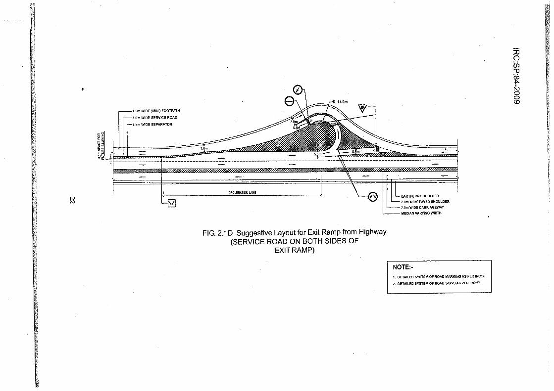
2.12.2.3 Wherever service roads are provided, provision shall be made for proper entryand exit ramps between the main highway and the service roads, duly keeping in viewfuture widening of main highway to six-lanes. The layout shall be as per Fig. 2.14to2jH.
2.'13 Grade Separated Structures
2.13.1 The type, location, length, number and the openings required and approachgradients for various grade separated structures shall be as specified in Schedule 'B' ofthe Concession Agreement. The approach gradient to the grade separated structure shallnot be steeper than 2.5 percent (1 in a0).
2.13.2 Vehicular underpass/overpass
The vehicular under/overpass structures shall be provided at the intersection of the ProjectHighway with all the National Highways and State Highways. Such under/over passes
18

1.5m WIDE{MlN.) FOOTPATH
7.0n WIDE SERVIcE ROAD
1.5m WDE SEPARATOR
E.ARTHERN SHOULDER
2.0m WIDE PAVED SHOULDER
7.0m WIDE CARRIAGEWAY
MEDIAN
FlG. 2.lASuggestive Layoutfor Entry Ramp to Highway(AT THE END OF SERVICE ROAD)
7aU)T]insI
N)OOCO

ffi
IIIIIi
i.
Ii
i
naØ3æÞ
IN)OO(o
l.5m wlDE (MlN.) FOOTPATH
7.0m WIDE SERVICE ROAD
I.5M WDE SEPARATOR
NOTE:-
1. DETAILED SYSTEM OF ROAD MARKING AS PER IRC:35
2. DETAILED SYSTEM OF ROAD SIGNS AS PER IRC:67
FlG.2.18 Suggestive Layout for Entry Ramp to Highway(SERVICE ROAD ON BOTH SIDES OF
ENTRY RAMP)
[i
H
fi
$t;
pi
V;1)
FI
HJ
Ë;ll
Ëi
H
H
ffi
Ëll
Ëii[i::
ËÌ!;:i
P¡
H
FiF¡i
F#
ffi
trim,t
ffi
ffi
H
ffi
ffi
ffi
ffi
&i
H
Ë
EAAÍ+iERN SHOULDER
ãIn q¡v¡DE PAVED SHOULDER
7.Om WDE CARRIAG€WAY
|MEDIAN VARYINGwlDTH
l\)

l\)
FlG.2.1C Suggestive Layout for Exit Ramp from Highway(AT THE END OF SERVICE ROAD)
l.5m WIDE (MlN.) FOOTPATH
7.0m WIDE SERVICE ROAD
1.5m WIDE SEPARATOR
EARTHERN SHOULDER
2.0m WDE PAVED SHOULDER
7.()m WIDE CARRIAGEWAY
MEDIAN
naU)3@s
IN)oo(o
Wl
ffi
ffi
ffi
Ë.
[l
F
r
t
I
I
7OU):uinÞ
I1\)OO(o
EARTHERN SHOULDER
2.0n WDE PAVÉo SHOULDER
7.0m WDE CARRIAGEWAY
MEDIAN VARYING WIDTH
FlG.2.1D Suggestive Layout for Exit Ramp from Highway(SERVICE ROAD ON BOTH SIDES OF
EX|T RAMP)
1.5m WDE (MlN.) FOOTPATH
7.0m wlDE SERVICE ROAD
'1.5m WIDE SEPARATOR
r!Ìi
,;. :
Erti
ti
Ëi
FJ
liåi
E,
h¡
Fr;
IiFi
Ë]
[.ßr:j
Þ.l¡
F.ì:
,þìr¡
. ct,l
þ:ì
ÈiÍFii
biFJËi¡i::tÉì1Þiti
þiËr
ffÞr!F'IY!-.
Ëii
ft
Ëi
H
H&iFrl
Þi
Ëi
[1
H
t\)t\)

1.5m WIDE (MlN.) FOOTPATH
7.0m WIOE SERVICE ROAD
1.5m WIDE SEPAUTORR 750ñ
N)(])
o
EARTHÊRN SHOULDER
2.0m wlDE PAVED SHOULDER
7.0m wlDE CARRIAGEWAY
MEDIAN
FlG.2.1E Suggestive Layout of Service Road Endingat a Junction with Cross-Road
NOTE:-
1. THE SUGGESTIVE LAYOUT SHOWS fuIEETING OF SERVICE ROAD
WITH ACROSS ROAD, THE I\¡OVE¡/ENTS FRO¡/ CROSS ROAD
ON TO THE I\¡AIN HIGHWAY SHALL BE DEAL-T IN ACCORDANCE
wtTH sEcTroN 2.2.1 (3).
2. THE OTHER END OF SERVICE ROAD SHALL BE PROVIDED WITH
END TREATMÊNT AS PER FIGURE 2,'1,8.
3. DETAILED SYSTEI\¡ OF ROAD MARKINGAS PER IRC:35
4. DETAILED SYSTEM OF ROAD SIGNS AS PER IRC:67
ÐaØ-uin5IlùOO(o

Ii
ffiFi
Fi
H]H¡¡!ÍìpiÊ,Jr¡lEi;i
H
1,5m WloE (MlN.) FOOTPATH
7.0m wlDE SERVICE RoAD1.5m WIDE SEPARATOR
tvÀ
EARTHERN SHOULDER
2.0m WIDE PAVED SHOULDER
MEDIAN
Fig.21F Suggestive Layout showing Configuration ofService Road, Entry/Exit Ramps, Side Road and Underpass
*:ffil
Wl
ffil
Hi
ffi
Ël
H
fr
Ii
II
l.I
I
!
ÐaCN
TooÀ
I1\)OO(o

l\)(Jr
FlG. 2.1G Suggestive Layout of Service Road Continuing at lntersection
EARTHERN SHOULDER
2,0m WIDE PAVED SHOULDER
MEDIAN
1.5m WIDE (MlN.) FOOTPATH7.0m WIDE SERVICE ROAD1.5m WIDE SEPARATOR
naØpæÞI
N)Oo(o

lRe :SP:84-2009
r

IRC:SP:84-2009
shall also be provided across other categories of roads carrying an average daily traffic
of more than 5000 Passenger Car Units (PCUs) on the date of inviting bids. The structure
may be either an underpass or an overpass depending upon the nature of terrain, vertical
profile of road, availability of adequate right of way, etc. Uhless othen¡uise specified inSchedule 'B' of the Concession Agreement, the Project Highway shall be carried at the
existing level in rural areas and the cross road would be either an underpass or overpass
and the entire cost involved in lowering or raising the existing cross road would be
included as part of the cost of the Project Highway. However, in urban areas, the cross
road shall be carried at the existing level, unless otherwise specified in Schedule'B' ofthe Concession Agreement. Decision whether the cross road or the Project Highway will
be carried at the existing level will be taken at the time of preparing the feasibility report
and would be based on considerations of drainage, land acquisition, provision of ramps
forthe grade separated facility, height of embankment and project economy etc.
2.13.3 Cattleand pedestrian underpass/overpass
These shall be provided as specified in Schedule'B'of the ConcessionAgreement.
¡) An underpass/overpass for crossing of cattle and pedestrians may not
be necessarywithin a distance of 2 km from Vehicular underpasses.
ii) The width of Pedestrian or Cattle crossing shall not be less than 5 m.
¡¡i) The pedestrian crossings shall have provision for movementof physically
challenged persons.
iv) Underpasses shall be preferred to overpasses.
v) Pedestrian underpass/overpass shallalso be provided within a distance
of 200 m from a school or hospitalorfactory/industrial area.
2.13.4 Road Over Bridges (ROBs)/Road Under Bridges (RUBs) shall be provided as
per Section-7 of this Manual.
2.14 Median Openings
2.14.1 Median openings shall not be spaced closer than 2 km. Additional controlled
openings shall also be provided for inspection, and diversion of traffic during repair and
rehabilitation.
2.14.2 Median opening shall not be provided in front of the service road entry. The
distance between the service road entry and the median opening shall be at least equalto
the sum of length of acceleration lane, weaving length, and deceleration length. Location
of opening shall be so decided as to minimize intraflow. This distance shall however be
not less than 150 m.
IRC:SP:84-2009
2,14.9 All median openings shallbe provided with additional3.S m wide shelter lane
by the side of median in both directions for waiting of vehicles to take U turn. Whereverrequired, horizontalgeometrics of the road shall be suitably adjusted.
2.14.4 Length of median opening shall not be less than 20 m.
2.15 Fencing
Fencing shall be provided between the service road and the Project Highway to prevent
the pedestrians, local vehicles and animals entering the highway. The fencing shall be
either of metal double beam crash barrier or pedestrian guardrail given in Para 9.10 ofthis Manual.
2.16 Typical Gross-sections
Typical cross-sections of Project Highway are given in Fig. 2.2 lo 2.10 for various
locations as below:
Ftg.2.2 shows typical cross section Type-A1 for 4-lane divided highway in open
country with isolated built-up area in plain/rolling terrain, without service roads and with
depressed median
Fig. 2.3 gives typical cross section Type-A2 for 4-lane divided highway in opencountry in plain/rolling terrain with service roads on both sides and with depressedmedian
Fig.2.4 shows typical cross section Type-A3 for 4-lane divided highway in opencountry with isolated built-up area in plaín/rolling terrain, without service roads and withraised median
Fig.2.5 gives typical cross section Type-44 for 4-lane divided highway in opencountry in plain/rolling terrain with service roads on both sides and with raised median
Fig.2.6 shows typical cross section Type-B for 4-lane divided highway in built-upsection in plain and rolling terrain with service roads on both sides and with raisedmedian
Fig.2.7 shows typical cross section Type-C1 for 4-lane divided highway on differentcontours in open countrywith isolated built-up area in mountainous terrain.
Fig. 2.8 shows typical cross section Type-C2 for 4-lane divided highway on differentcontours in built uo section in mountainous terrain.
Fig. 2.9 shows typical cross section Type-C3 for 4-lane divided highway at same level
in open countrywith isolated built-up area in mountainous terrain.

f\)
TYPICAL CROSS SECTION WPE-41(Open country-Plain / Rolling terrain)
Fig :2.2 4-Lane Divided Highway without Service Roads and with Depressed Median
Comber/Superelevol
o
ombey'Superelevotion
TYPICAL CROSS SECTION TYPE-Az(Open country-Plain / Rolling terrain)
Fig : 2.3 4-Lane Divided Highway with Service Roads and with Depressed Median
Ccmber/Superelevoti
.50m
rlcolot I
ËÉtuØ¡
nc)ct)3æÀ
I
I\)oO(0

TYPICAL CROSS SECTION TYPE-A3(Open country-Plain / Rolling terrain)
Fig:2.4 4-Lane Divided Highway without Service Roads and with Raised Median
Co mber/Superelevotìo
c)l colÐl 9!oo I : on! I vc-a I uln
I-YPICAL CROSS SECTION TYPE-A4(Open country-Plain / Rolling terrain)
Fig : 2.5 4-Lane Divided Highway with Service Roads and with Raised Median
Comber/Superel evoti
floci)3æ5
I
N)OoCO
Co mbey'Su perelevoti
o@
3.3U)

õo
¡>uø
U1
O.
3åL!
L-
J
öornerl Ko¡iln9
TYPICAL CROSS SECTION TYPE-B(Built - up Section - Plain/Rolling terrain)
Fig : 2.6 4-Lane Divided Highway with Service Roads and with Raised Median
Crosh Borrìer
oc
õôLL
õø
",.9x>AB
U)
TYPICAL CROSS SECTION TYPE-C1(Open country - Mountainous terrian)
Fig:21 4-Lane Divided Highway on Different Contours
ÐaU)3æs
I
l\)oO(o

Ðoci)-uö5
IN)oo(o
TYPICAL CROSS SECTIO.N TYPE-C2(Built up section - Mountainous terrian)
Fig : 2.8 4-Lane Divided Highway on Different Contours
ring woll
lley side
TYPICAL CROSS SECTION TYPE-C3(Open country - Mountainous terrian)
Fig : 2.9 4-Lane Divided Highway at same levelwith Raised Median
F
fi
H
ffi
H
gd
F¡
ffi
ffi
ffi
ffi
ë
(¡)N)

\\-\\ _c
xCIü *q_'ño,io*LL
Rocdwoy(20.0m)
0.25m -- - Ker[ $hy
TYPICAL CROSS SECTION TYPE.C4(Built up section - Mountainous terrian)
Fig:2.10 4-Lane Divided Highway at same level with Raised Median
Ccrriogeway
0.25merb Shy
.Cvn(h -ttu'ãoño-t!
--_\__\\_\
oining wall
Vclley side
-_____\
Ðc)U)tlinÞI
N)Oo(o

IRC:SP:84-2009
Ft9.2,10 shows typical cross section Type-C4 for4-lane divided highway at same levelin built up section in mountainous terrain.
2.17 Capacity of Four-lane highway
Forthe purpose of augmentation of the facilities and upgradation of the Project Highway,the design service volume for different terrain conditions and level of service shall be asspecified in Table 2.9.
Table 2.9 Design Service Volume for Four-lane Highways in PGUs per day
Terrain Design Service Volume in PGUs per day
Level of Service 'B' Level of Service 'G'
Plain and Rolling 40,000 60,000
Mountainous and Steep 20,000 30,000
/Vofe ;The definition of PCU here is as per IRC Codes and Guidelines and not thedefinition given in MCA
2.18 Warrants for Six-Laning
Unless otherwise specified in the Concession Agreement, the Project Highway shall bewidened to 6-lane when total traffic including the traffic on service roads, if any, reachesthe design service volume corresponding to Level of Service 'C' for 4-lane highwayspecified in Table 2.9.
::
I:
34

SECTION .3
INTERSECTIONS AND GRADE SEPARATORS


IRC:SP:84-2009
SECTION .3
INTERSECT¡ONS AND GRADE SEPARATORS
3.1 Introduction
3.1.1 The intersections to be provided shall be one of the following types:
¡) At-grade lntersections
ii) Grade separated lntersections without ramps
iii) lnterchanges
The types and locations of lntersections, lnterchanges and Grade-separatedlntersections without ramps shall be based on requirements stipulated in IRC:SP:41,IRC:5, IRC:92, MORTH Specifications for Road and Bridge works. These shall bespecified in Schedule 'B' of the Concession Agreement.
3.1.2 The existing intersections, which are deficient with respect to the minimumrequirements shall be improved to the prescribed standards. Additional land, if any,required for improving the existing intersections shall be provided bytheAuthority.
3.2 At-grade lntersections
3.2.1 The type of intersections to be adopted shall be decided on the basis ofparameters like number of intersecting legs, traffic volume/speed, type of traffic controletc. Properly designed intersections shall be provided at all at-grade crossings. Rotaryshall not be provided.
3.2.2 i) The intersections shall be designed having regard to flow, speed,composition, distribution and future growth of traffic. Design shall bespecific to each site with due regard to physical conditions of the siteavailable. The design of different elements of intersection shall be doneas per IRC:SP:41 "Guidelines on Design ofAt-grade lntersections in Ruraland Urban Areas" including other criteria given in this Manual.MORTH - Type Designs for lntersection on National Highways may alsobe referred to, wherever required to develop suitable layout and design ofAt-grade I ntersections.
ii) At multi leg intersections, the points of conflict should be studied carefullyand possibilities of realigning one or more of the intersecting legs andcombining some movements to reduce the conflicting movements shallbe examined. The object shall be to simplify the design and appropriatecontrol devices added to ensure more efficient and safe operation.

IRC:SP:84-2009
iii) The channelising islands shallstartfrom the edge of the paved shoulder.This principle shall also apply in case of MORTH - Type Designs forlntersections on National Highways.
3.2.3 Cross roads shalljoin directly on to service roads and the entryto and exitfromthe Project Highway shall be through end connections as shown in fig. 2.14 to H.
3.3 Grade separated lntersections and lnterchanges
3.3.1 Grade separated intersections, without ramps, shall be provided at locationswhere traffic on cross roads is moderate to heavy. Under this type, two cross roadsseparate at different grades (as Road Under Bridge or Road Over Bridge). The accessfrom Project Highway to the cross roads in case of such grade separated intersectionswithout ramps, shall be through other existing roads/ service roads.
3.3.2 An interchange is justified at locations where traffic on cross road is heavy andan at grade intersection fails to handle the volume of turning, merging and diverting traffic.
3.3.3 Geometric standards for design
The geometric design standards for various elements of grade separators shall be asgiven in IRC:92. Gradient for approaches shall not be steeper than 2.5 percent (1 in 40).
3.3.4 Design of structures
Design of structures shall conform to Section 7 of this Manual. Minimum length of viaductrequired to be provided shall be specified in Schedule'B'.
3.3.5 Lighting
Lighting requirement shall be as per Section 12 of this Manual. The top and underside ofthe grade separated structures and interchange area at the ground level upto 50 mbeyond the point from where flaring of the main carriageway takes place shall beprovided with lighting.
3.4 Detailed Design and Data for Review by the lE
The Concessionaire shall submit the details of the ground surveys, traffic data, trafficforecast, design and drawings of the intersections and interchanges showing all safetyfeatures to the lndependent Engineer for review and comments, if any.
".lil.i-'--::'ì.::.j=i-îi1:iì;ì,fiit1tì;î1,,.::-:ì:r-:i|Ìïl: lti,arii;'-=íiilw
I
.
3B

SECTION .4
EMBANKMENT & CUT SECTIONS

4.1
IRC:SP:84-2009
SECTION .4
EMBANKMENT & CUT SECTIONS
General
4.1.'l The design and construction of the road in embankment and in cuttings shallbe carried out in accordance with Section 300 of MORTH Specifications and therequirements, and standards and specifications given in this Section. This Section alsocovers specifications for sub-grade and earthen shoulders.
4.'1.2 Efforts should be made to remove the inherent deficiencies in plan and profileof the existing road. The final centre line of the road and the road levels shall be fixed dulyconsidering all the relevant factors covering structural soundness, safety and functionalrequirements as per relevant IRC Codes and provisions of this Manual.
4-1.3 The existing road embankment shall be widened/modified to the specifiedcross-sectional details.
4.2 Embankment
4.2.1 The height of the embankment shall be measured with respect to the finishedroad levels. The following principles shall be kept in view while fixing the road level:
i) No section of the road is overtopped. The finished road level shall be atleast 0.6 m above ground level (except in cutting and transition length).
ii) The bottom of sub-grade is generally 1.0 m above the high flood level/high water table. However, in the case of existing old roads where it maybe difficult to fulfillthis criterion without needing reconstruction or raisingin substantial length, the criteria may be relaxed depending on siteconditions, ensuring that the bottom of sub-grade is 0.6 m above HighFlood Level (HFL). The HFL should be decided by intelligent inspections,local observations, enquiries and studying the past records. lf raising ofany section(s)of the existing road is required, the same shall be specifiedin Schedule 'B'of the Concession Agreement.
4.2.2 Materials and physical requiremgnts
4.2.2.1 Sourcing of materials for embankment and subgrade construction, as well ascompliance with environmental requirements in respect of excavation and borrow areasunder the applicable laws shall be the sole responsibility of the Concessionaire.
4.2.2.2 The material to be used in sub-grade shall satisfy the design CaliforniaBearing Ratio (CBR)at the specified density and moisture content.
L
-
-
À4+t

IRC:SP:84-2009
4.2.2.3 The embankment and subgrade shall be compacted to satisfy the minimum
compaction requirements given in Clause 305 of MORTH Specifications.
4.2.3 Structural teaturås and design of embankment
4.2.3.1 Embankment with height 6.0 m or above shall be designed in accordance with
IRC:75 taking into account slope stability, bearing capacity, consolidation, settlement and
safety considerations based on geotechnical and investigation data. Where theembankment is to be supported on a weak stratum, appropriate remedial/groundimprovement measures shall be taken.
4.2.3.2 Side slopes shall not be steeperthan 2H:1V unless soil is retained by suitablesoil retaining structures.
4.2.3.3 The side slopes shall be protected against erosion by providing a suitablevegetative cover, kerb channel, chute, stone/cement concrete block pitching or any othersuitable protection measures depending on the height of the embankment andsusceptibility of soilto erosion. Drainage arrangement shall be provided as per Section 6
of this Manual.
4.2.4 Use of pond ash for embankment construction
Where pond ash is used for embankment construction in pursuance of the instructions ofthe Ministry of Environment and Forests or othen¡uise, the embankment shall be designedand constructed in accordance with IRC: SP:58.
4.3 Roadway in Cutting
The road level shall be fixed, keeping in view the provisions of relevant IRC Codes.
4.4 Soil lnvestigations and Design Report
4.4.1 General
The Concessionaire shall carry out necessary soil suryeys, and field and laboratoryinvestigations for selecting appropriate borrow pits, identifying and treating problematicground locations, if any, and for finalizing structural features and design of theembankment and cut sections and establishing improved ground properties. A report onthe soil investigation shall be furnished along with the design.
4.4.2 Soil investigations for embankment
Soil investigations shall cover the following:
a) Soil investigations and tests in accordance with the requirements specified
* in IRC:SP:19 and shall be reported in the Proforma given in Táble 1 of
42
r'j:::::5i.
:;

IRC:SP:84-2009
IRC:SP:19. ln addition to this, all tests as perthe requirements of MORTHSpecifications shall be reported.
b) ln respect of embankments with height more than 6 m, additionalinvestigations and soiltests as per IRC:75 and Appendix 10 of IRC:SP:19.
c) lnformation regarding the topography, high flood level, naturaldrainageconditions, highest sub-soil water level, and the nature and extent ofinundation, if any.
d) The characteristics of embankmentfoundation including the presence ofany unsuitable/weak strata, marshy areas, water logged areas, etc.
e) Along the alignment of the road, where unstable strata, soft material orpoor subsoil conditions have been met with at the foundation level, thesoil profile shall be drawn after determining through borings, the type ofsoilat different levels. The borings shall be at maximum interval of 100 mto a depth of 2 m or more below the existing ground as necessary. ln thecase of high embankments, the borings shall be taken down to a depthequalto twice the height of the embankment.
0 Any particular construction problems of the area or other importantfeatures.
g) Geotechnical properties of pond ash, covering parameters specified in
Table 1 of IRC:SP:S8 and Optimum Moisture Content (OMC)- dry densityrelationship for heavy compaction. This information shall be furnished, in
case pond ash is used in embankment construction.
4.4.3 Soil investigations for cut sections
Soil investigations and tests shall be carried out in accordance with the requirementsspecified in IRC:SP:19 and information regarding depth of water table, seepage flow,presence of any weak, unstable or problematic strata.
4.4.4 Design Report
The Concessionaire shall prepare the design report with all relevant details including thefollowing:
i) Road Embankment
a) The detailed design of the embankment, remedial/groundimprovement treatment where required. For embankments withheight more than 6 m, construction methodology should also beincluded.
b) Design of retaining walls/reinforced earth structures.
43

IRC:SP:84-2009
Design of protection measures for embankment slope and drainagearrangement.
Design of pond ash embankment in case use of pond ash is
proposed.
Any additional information relevant to the design of embankment.
Cut Section
a) Type of cutting involved and proposed cut slopes shall be provided
in accordance with the nature of the soil encountered. Whererequired, benching including use of slope stability measures likepitching, breastwalls, etc. shall be adopted to make the slopes stable
and safe
b) Design and details of erosion control, slope protection measures,etc.
ln cut sections in hilly terrain, the problem of seepage flow is common.
Where such conditions exist, necessary measures shall be takenincluding provision of deep side drains to intercept the seepageflow and discharge the drained water into suitable outlets to avoidany damage to road and cut slopes. Design and details of drainagearrangement for sub-soil and surface water shall be furnished. ltshould be ensured that rain water and seepage water is quickly
drained out. The gradient of drain shall not be flatterthan 1 in 200.
Any other additional information relevant to the design of cut slopes.
r=rfJir...n-,Ê'ff',aÊ;ìç g *-.*ffi
-,
i;
:,
ii)
c)
d)
e)
c)
d)
44

SECTION .5
PAVEMENT DESIGN


IRC:SP:84-2009
SECTION .5
PAVEMENT DESIGN
5.1 General
5.1.1 The design and construction of new pavement sections, and of strengtheningmeasures (overlay) forthe existing pavement shall be carried out in accordance with thecriteria, standards and specifications given in this section. Where alternativespecifications or materials are proposed to bring in innovation in design etc., provisionsof Para 1 .'1 2 of this Manual shall apply.
5.1.2 The design of new pavement sections or strengthening of existing pavementsshall take into account all relevant factors for assuring reliable performance and shall alsosatisfy the specified minimum performance requirements.
5.1.3 The Concessionaire shall undertake the necessary soil, material and pave-ment investigations and traffic volume and axle load studies in accordance with the goodindustry practice for preparing detailed designs.
5.1.4 The materials, mixes and construction practice shall meet the requirementsprescribed in the MORTH/IRC Specifications.
5.1.5 Where problematic conditions such as expansive soils, swamps or marshes,flooding, poor drainage, frost susceptible areas etc. are found to exist, adequatemeasures shall be adopted to dealwith such site conditions.
5.2 Type of Pavement
5.2.1 Unless otherwise specified in Schedule 'B', the Concessionaire may adoptany type (flexible/rigid) of pavement structure for new construction.
5.2.2 Strengthening of the existing flexible pavementwill be carried out by providingappropriate bituminous overlay, unless specified otherwise in Schedule 'B' of theConcession Agreement.
5.2.3 TheAuthority may require provision of cement concrete pavement on the newcarriageway and/or replacement of existing pavement depending upon specific siteconditions. Such requirements shall be as specified in Schedule 'B' of the ConcessionAgreement. The minimum design, construction, performance and maintenancerequirements for cement concrete pavements will be specified by the Authority andSchedule-K of the Concession Agreement will be modified accordingly.
47

IRC:SP:84-2009
5.3 Method of Design - New Pavements
5.3.1 Method of design of flexible pavement
The new pavement shall be designed in accordance with the IRC: 37 Guidelines for the
Design of Flexible Pavements.
5.3.2 Method of design of rigid pavement
Rigid pavement shall be designed in accordance with the method prescribed in IRC:58
"Guidelines for the Design of Plain Jointed Rigid Pavements for Highways"'
5.4 Design Requirements for New Pavement Sections
5.4:1 Flexible pavement - design period and strategy
i) Flexible pavement shall be designed for a minimum design period of 15
years or operation period, whichever is more. Stage construction will be
permissible subject to the requirements specified in para (ii) below.
ii) Alternative strategies or combination of initial design, strengthening and
maintenance can be developed by the Concessionaire to provide the
specifìed level of pavement perf,ormance over the operation period subject
to satisfying the following minimum design requirements'
a) The thickness of sub-base and base of pavement section is designed
for a minimum design period of 15 years or the operation period,
whichever is more and the initial bituminous surfacing for a minimum
design period of 10 years.
b) The pavement shall be strengthened by bituminous overlay as and
when required to extend the pavement life to full operation period.
The thickness of bituminous overlaV shall be determined on the basis
of IRC:B'1.
5.4.2 Rigid pavement - design period and strategy
¡) Rigid pavement shall be designed for a minimum design period of 30
!êâ:rs. The stage construction shall not be permitted'
ii) The Pavement Quality Concrete (POC)shall rest over Dry Lean Concrete
(DLC) subbase of 150 mm thickness.
ili) The DLC will meet the minimum cement and compressive strength
requirement as prescribed in IRC:SP:49. DLC will extend beyond the PQC
(including that in shoulder, if any) by 0.5 m on either side.

s.4.3
IRC:SP:84-2009
iv) Below DLC layer, a properly designed drainage layer Granular Sub Base(GSB) of 150 mm thickness shall be provided throughout the road width.It shall be designed to obtain a drainage coefficient of not less than 20 mper day.
Pavement performance requ irements
i) The pavement structure shall be capable of giving the specifiedperformance overthe entire operation period.
ii) The new pavement sudace shall satisfy the following standards,
a) Suface Finish As per requirements ofClauses 902 and 903 ofMORTH Specifications
Not more than 2000 mm/km foreach lane in a km lenqth
b) Roughness in each lane
c) Rutting
ln wheel path measured N¡l
by3mStraightEdge.
d) Cracking or any other distress Nil
iii) During the operation period, the pavement surface roughness or anystructural or functional distress shall not exceed the values specified in
Schedule-K of the Concession Agreement. Generally the pavementcondition in terms of roughness, cracking and rutting should not deteriorateto the maximum values specified in Schedule-K for rectification, earlierthan 5 years from the original level/ from the year of rectification. Anytreatment in the form of renewal/ overlay carried out or required to restore/correcV improve the riding quality or any distress shall be of such thicknessand specification that will restore the riding quality to roughness notexceeding 2000 mm/km.
iv) During the operation and maintenance period, the pavement strength shallbe evaluated periodically through deflection measurements (Refer to para5.8 (ii)of this Section)and the stretches exhibiting any structuraldeficiencyshall be rectified.
5.5 Design Traffic
5.5.1 The design traffìc shall be estimaied in terms of cumulative number of standardaxles (S160 kg)to be carried by the pavement during the design period.
5.5.2 Estimate of the initial daily average traffic flow shall be based on at least7 days, 24 hr classified trafiic counts. IRC:9 may be used as guidance for carrying out the
traffic census.
49

IRC:SP:84-2009
5.S.3 Any likely change in traffic due to proposed four laning of the facility and/or
future developmeni ptans, land use, shall be dqly considered in estimating the design
traffic.
S.S.4 Traffic growth rate shall be established for each category of commercial
vehicles to be .onéid"r"d for design of pavement. For traffic projections, the procedure
ouilined in IRC:10g may be followãd. The Concessionaire shall adopt a realistic value of
the rate of traffic growth, provided that annual rate of growth of commercial vehicles shall
not be adopted less than 5 Percent.
S.5.5 The design traffic in case of service road shall be five million standard axles'
The crust composition shall be provided accordingly.
5.6 Sub-grade
The subgrade, whether in cut orfill, shall meet the requirements stipulated in Clause 305
of MORIH Specifications. The thickness of subgrade shall not be less than 500 mm
5.7 Pavement Components and Materials
¡) The pavement construction materials for sub-base, base and bituminous
surfacing shall conform to the requirements prescribed in MORTH
Soecifications and IRC Standards.
ii) Where several materials will adequately serve as component within the
pavement structure, such as a sub-base or a base course, the
Concessionaire shall have the option of using any of the materials/
specifications, subject to sound engineering practice and product quality
requirements.
5.8 Performance Evaluation
i) Roughness in each laneforfulllength shallbe measured bi-annually using
appropriate approved method and equipment.
ii) The structuralevaluation of the pavementshall be made bytaking deflection
measurements every 5 years in accordance with the procedure given in
IRC:81, unless needed earlier for stretches exhibiting severe distress
during the operation and maintenance period.
5.9 Strengthening of Existing Pavements
5.g.1 Before strengthening treatment is prescribed, a detailed pavement condition
survey and evaluation shall be carried out in accordance with IRC:81 to determine
i) The extent of distress and nature of deficiency in the existing pavement
structure, and

IRC:SP:84-2009
i¡) Whether any special treatments e.g. provision for remedying reflectioncracking, pavement internal drainage, sub-grade improvement/reconstruction, or rectification of any other deficiencies are warranted.
5.9.2 Necessary corrective measures to treat the identified deficiency shall be takenalong with strengthening of the pavement.
5.9.3 ln stretches where the pavement is damaged/deteriorated to such an extentthat the use of Benkelman Beam method may not result in a realistic assessment of thestrengthening treatment, pavement shall be designed as new pavement.
5.9.4 Where an existing pavement is built over an untreated expansive/black cotton
soil subgrade, its improvement/ strengthening shall be treated separately. Such stretchesshall require reconstruction with provision of necessary measures such as replacemenVtreatment of expansive subgrade, drainage, etc. as per the prescribed specifications and
IRC:37; and shall be designed as new pavement. Stretches to be reconstructed, whetherdue to expansive subgrade or having grossly deteriorated, etc. shall be specified in
Schedule 'B'of the Concession Agreement.
5.9.5 No granular layer shall be provided over an existing bituminous surfacing.Situations may arise where it is envisaged to strengthen grossly deficient existing road
with a granular layer in addition to the bituminous overlay, or where for camber and/orgrade correction substantial thickness of profile corrective course is needed. ln suchcases, the existing bituminous surfacing shall be completely removed by scarifyingimilling and then the pavement built up with the granular layer(s)and bituminous overlay.
The thickness and composition of bituminous surfacing (Binder course and Wearingcourse) overthe granular layershallconform to IRC:37.
5.9.6 Design of Overlay
i) The thickness of the bituminous overlay shall be determined on the basisof Benkelman Beam Deflection Technique and the design traffic as per
the procedure outlined in IRC:81 "Guidelines for Strengthening of FlexibleRoad Pavement using Benkelman Beam Deflection Technique" as alsofrom structural numbers of existing pavement layers.
ii) The design period will be the same as specified for the new pavement
sections vide Para 5.4.1 of this Section. The initialstrengthening shall be
dohe for a minimum design period of 10 years. Subsequent strengtheningto extend the pavement to full operation period shall be implemented atthe end of initial design period or earlier, in case of any structural distressin the pavement or if the surface roughness exceeds the value specifiedin Schedule'K' of the Concession Agreement.
iii) The design traffic will be estimated as per the procedure described fornew pavement.
Ìr
l]i
Ãl

IRC:SP:84-2009
iv) The thickness of bituminous overlay for pavement strengthening shall not
be less than 50 mm bitumino.us concrete, after attending to the- requirements of profile corrective course.
5.9.7 Bituminous mix for overlaY
i) The specifications for the bituminous mixes for the overlay shall be as
specified for bituminous surfacing for new pavement sections.
ii) Design of recycled mixwhere provided shall conform to the requirements
of Clause 517 of MORTH Specifications.
5.9.8 Pavement performance requirements and evaluation
i) The strengthened pavement shall satisfy the minimum standard and
maintenance requirements specified for new pavement sections in this
Manual and Schedule-K of the Concession Agreement'
ii) The performance measurement and evaluation will be done as given in
this Manual.
5.10 Paved Shoulders
i) Paved shoulders shall be provided as specified in this Manual
ii) lf the thickness of the existing paved shoulder, if any, is less than the
thickness of the existing pavement, the paved shoulders shall be
reconstructed to the pavement thickness in the adjoining carriageway.
5.11 Construction, Workmanship and Quality of Works
All materials, construction operations, workmanship, surface finish and quality of
completed construction for all pavement works including sub-grade, sub-base, base
course, bituminous surface courses for both new pavement and strengthening of existing
pavements, shoulders, service roads, etc. shall conform to the specified requirements
and comply with the provisions of Section 900 of the MORTH Specifications.
5.'12 Premature Distress
Notwithstanding the minimum design, specifications and standards specified in the
preceding paras for new pavements and strengthening of existing pavements, if the
pavement shows premature distress in the form of cracking, rutting, patching, loss of
camber or any other structural or functional distress, necessary remedial measures by
strengthening/resurfacing/recycling shall be underlaken for conforming to the minimum
requirements prescribed in Schedule 'K' of the Concession Agreement. ln case of
reoetition of the distress, reconstruction shall be resofted to after proper investigations'
52

IRC:SP:84-2009
5.13 Detailed Design Report
5.13.1 The new pavement design and strengthening proposals formulated on the
basis of the detailed investigations and studies shall be sÛbmitted to the lndependentËngineer alongwith Data Collection, Data Evaluation and Design Reports.
5.13.2 Data collection
Following details shall be included in the report:
i) Soil investigation data for new pavements as perTable 13.2 of IRC:SP:19.
Report shall include OMC-dry density relationship with heavy compaction
and soaked CBR values in addition to other data and information as per
the prescribed Proforma.
ii) Test values of aggregate for pavement courses as per Tables 13.3 and
13.4 of IRC:SP:19. All tests as per requirements of MORTH Specificationsshall be reported in addition to the tests and information included in theabove mentioned Tables.
ii¡) Classified traffic counts in Proformal of IRC:SP:19.
iv) Axle load surveys and VDF values for each category of commercialvehicles as per Proforma 4 of IRC:SP:19.
v) Estimation of traffic growth and traffic projections for pavement design.
vi) Pavement condition data in the Proforma given in Table 2 of IRC:81.
vii) Pavement roughness data determined through appropriate method as
approved by the Authority.
viii) Pavement Deflection Data measured by Benkelman Beam as per theprocedure detailed in IRC:81 . Pavement deflection data shall be recorded
in the prescribed Proforma vide Table 3 of IRC:81. The deflection data
shall be accompanied with the characteristics of the sub-grade soil
covering type of sub-grade soil, field moisture content (at the time ofdeflection survey), average annual rainfall in the area, and pavement
temperature at the time of deflection survey.
ix) Any other relevant information required by the lndependent Engineer forreView and comments, if anY.
5.13.3 Data evaluation
The report shall inter alia cover:
i) Data evaluated - soil characteristics and subgrade strength, pavement
distress, pavement deflection, riding quality, skid resistance, drainageaspects, etc.
53

nìW@&eËê'g'rF's¿%ú:r$sì¡tiÈù:l{M4iJ?ætur:"*-**---_- ' -
IRC:SP:84-2009
ii) Pavement deficiencies, drainage and constraints'
iii) Any other relevant details.
5.13.4 Detailed design
The Report shall contain the detailed design of the preferred solution along with any
specialtreatment proposed for adoption. Añy departures from the specifications stated
herein shall be ruppôrt"O with authentic standards and specifications and accepted
practice.
54

SECTION .6
HIGHWAY DRAINAGE

IRC:SP:84-2009
, SECTION .6
HIGHWAY DRAINAGE
"',
6.1 General
6.1.1 The design and construction of surface and subsurface drains for highwaydrainage shall be carried out in accordance with the requirements of this Section.
6.1.2 For efficient drainage system for the entire Project Highway includingstructures and facilities, directions contained in Clause 309 of MORTH Specifications,IRC:SP:42 and IRC:SP:5O as relevant shall be followed.
6.1.3 ln road sections in cuttings and at underpasses where it may not be possible todrain out the water using gravity flow, necessary arrangement for pumping shall be made.
6.1.4 Detailed survey for levels along the proposed longitudinal drains shall be
carried out on both sides of the Froject Highway. The bottom levels of these drains shallmeetthe culverts and bridges.
6.2 Surface Drainage
6.2.1 The selection of type of roadside drains shall be based on the magnitude and
duration of flow. The roadside drains shall be designed on the principles of flow in openchannel.
6.2.2 The road side drains shall not pose any danger to traffic, slopes of cuttings,embankment, pavement or structures.
6.2.3 As far as possible, longitudinal slope shall not be less than 0.5 percentfor lined
drains and 1.0 percent for unlined drains. Permissible non-erodible flow velocity forcorresponding earth surface as mentioned in Clause 9.4 of IRC:SP:42 shall be keptin view
6.2.4 The side slopes of the unlined drains shall be as flat as possible and shall notbe steeper than 2H: 1V.
6.2.5 The drains shall be provided with CC lining in the following situations:
i) When due to space constraint, the drains are located nearthe toe of theembankment or near structures.
ii) Drains located in built-up areas.
iii) Flow velocity is more than 0.3 m to 1 m/s in silt and sand; and more than1.5 m/s in stiff clay.
57

IRC:SP:84-2009
6.2.6 ln built-up areas, covered or piped drains, with manholes at suitable intervals
to desilt the pipe's, shall be provided.
6.3 Median Drainage
6,3.1 proper arrangement for drainage of median shall be provided' The median
drain should have adãquate longitudinãl slope to the nearest culvert to drain off
transversely.
6.j.2 ln case the carriageway is sloping towards unkerbed median (widerthan 5 m),
provision of a central swale sha¡i Oe madeJor drainage of the median. The swale shall
rtop" longitudinally for drainage, water intercepted by inlets at intervals and discharged
through transverse drains into outlet channel'
6.3.3 Median of width 7 m or less shall be turfed or paved and could be crowned for
drainage across the Pavement.
6.3.4 ln superelevated sections, proper arrangement for drainage of raised
carriageway and median shall be made without allowing water to drain on the other
carriageway.
6.4 Drainage of Embankment with Height Above 3 m
6.4.1 ln embankments with height more than 3 m and approaches to bridges,
special arrangement for protection of embankment slopes shall be essential in order to
ensure that embankmentslopes maintain their shape during the monsoon season. ln this
respect, directions contained in Clause 7 of IRC:SP:42may be followed as appropriate
forthe climatic conditions of the area of the Project Highway.
6,4,2 Drainage arrangement shall include provision of kerb channel at the edges of
the roadway to chãnnelise the water, and Cement Concrete (CC) lined chutes along the
slopes at designed intervals to discharge the water into side channels at the bottom
alongwith appropriate protection of the slope. The slope protection materialand chutes
shall be kept well maintained at alltimes.
6.4.3 The chute drains and drains at toe of the embankment shall be of Plain Cement
Concrete (M 15 grade), over proper bedding.
6.5 Catch Water Drains
6.5.1 Suitable catch water drains shall be provided on the hill slope above cutting to
collect and remove surface water run-off from upper reaches. These drains shall be of
trapezoidalshape and stone lined and cement pointed.
6.5.2 The catch water drains shall be designed to carry the intercepted waterto the
nearest culvert or natural drainage channel.

IRC:SP:84-2009
6.5.3 lt shall be ensured that the catch water drains are provided in stable hill slopesoutside the periphery of slide/unstable areas.
6.5.4 Where required, lined chutes shall be provided to lead the discharge to thecatch pit of culvert or to a natural drainage channel.
6.6 Sub-surface Drains
6.6.1 The sub-surface drainage shall be provided
i) for lowering the level of water table for drainage of sub-grade;
ii) to intercept or drain out free water in cut slopes; and
iii) for drainage of pervious subbase in situations where it may not bepracticable to extend the subbase across the shoulder.
6.6.2 Sub-surface drains shall not be used for surface drainage.
6.6.3 The sub-surface drains shall be:
i) Close jointed per-forated pipes or open jointed unperforated pipes intrenches with backfill materialaround pipes.
ii) Aggregate drains consisting of free draining material in the trench withoutany pipe.
6.6.4 Perforated pipes and unperforated pipes shall meetthe requirements of Clause
3O9.zof the MORTH Specifications.
6.6.5 The internal diameter of the pipe shall not be less than 150 mm.
6.6.6 The sub-surface drains shall be located not less than 0.5 m below the
sub-grade.
6.6.7 Backfillmaterial:
i) Backfill material shall be free draining sand, gravel or crushed stonedesigned on inverted filter criteria for filtration and permeability, or of an
appropriate grading conforming to the requirements of Table 300.3 of the
MORTH Specifications.
ii) Thickness of backfill material around the pipe shall not be less than 150
mm. The minimum thickness of materialabove the top of the pipe shall be
300 mm.
6.6.8 Sub-surface drains outside the road pavement shall be sealed at the top to
avoid percolation of surface water into these drains.

ÌRC:SP:84-2009
6.6.9 Use of Geo-textile
i) The sub-surface drains may be designed using appropriate geotextile to
serve the functions of filtration and separation'
ii) The sub-surface drains can be provided with geotextile either along the
trench or around the PiPe or both'
iii) The geotextile shall satisfy the requirements of Clause 702 of the MORTH
SPecifications.
6.6.10 Trench excavation, laying of pipe, backfilling, and use of geosynthetics shall
conform to the requirements of clause 309.3 of the MoRTH Specifications'
6.6.11 The drain outlet shall be a free outlet and shall be provided as per
Clause 309.3 of the MORTH Specifications'
6.6.12 Aggregate drains
i) The trench for aggregate drain shall be of minimum 300 mm width and cut
to a depth to expose the granular pavement courses to be drained.
¡¡) Aggregate forthe drain shall be gravel, stone aggregate or slag of grading
as PerTable B of IRC:SP: Z'
iii) The aggregate drain shall be provided with a geo-textile wrap to act as
filtration and seParation laYer'
6.6.13 Design of subsoildrainage shallbe based on a rational basis. Reference may
be made to IRC:SP:42'
6.7 lnternal Drainage of Pavement Structure
i) Boxed type construction in which pavement is housed in earlhen shoulders
shall not be Provided.
ii) The sub-base shall be extended across the shoulders for efficient drainage
of Pavement.
iii) The granular sub-base shall be of proper design and grading to perform
satisfactorily as a drainage layer. The drainage layer shall not have material
finerthan 75 micron size.
iv) A suitable filter of granular material or geotextile to act as filtration and
separation layer shall be incorporated, where necessary, between the
sub-grade and sub-base to prevent clogging'
60

IRC:SP:84-2009
6.8 Survey, lnvestigation and Design Report
The Concessionaire shall carry out proper surveys and investigations for detailed designof the drainage system. The proposal for drainage system supported with surveyinvestigation report and detailed design report shall be submitted to the lndependentEngineerfor review and comments, if any.
6.8.1 Drainage studies
The survey and investigation and drainage studies shall include:
i) Alignment plan, longitudinal and cross sections, contour map.
ii) Hydrologicaldata
Drainage area, water shed delineation, direction of flow, location ofoutfalls, existing surface drains, ground surface condition, rainfall, floodfrequency, etc.
iii) Data for hydraulic design of drains
iv) Geo-technical investigations for sub surface strata, level of water table,seepage flow etc.
v) ldentification of areas requiring sub-surface drainage.
vi) Any other relevant information
IRC:SP:19, IRC:SP:42, IRC:SP:48 and IRC:SP:SO may be referred to.
6.8.2 Design details
The report shall include:
i) Estimation of design discharge.
ii) Design of surface drains.
iii) Design of sub-surface drains.
iv) Drainage arrangement plan along with cross section of drains withlongitudinal levels, cross drainage works and a strip char1.
v) Specifications of drains.
vi) Any additional information as required by the lE for review of the drainagesystem.
6.8.3 Responsibility for design and adequacy
The Concessionaire shall be fully responsible for design and adequacy of the drainagesystem throughout the operation period as per the requirements of the ConcessionAgreement.
ol


SECTION .7
DESIGN OF STRUCTURES


7.1
IRC:SP:84-2009
SECTION .7
DESIGN OF STRUCTURES
General
i) All bridges shall be designed in accordance with the relevant Codes,Standards and Specifications and Special Publications and Guidelinesof the lRC. All construction of bridges shall conform to MORTHSpecifications for Road and Bridge Works.
ii) All bridges shall have independent superstructure for each direction oftravel unless specified otherwise in Schedule'B'. Culverts may have singleor independent superstructure.
¡ii) All bridges shall be high level bridges unless specified otherwise in
Schedule 'B' of theConcession Agreement.
iv) Viaduct spans shall be provided if the height of solid embankment in
built-up sections is more than 5 m.
v) The width of median in the culvert and bridge portion shall, as far aspossible, be kept same as that in the approaches. ln case width of medianis different from that of approach section due to site constraints, suitabletransition shall be provided near approaches for guiding vehicular traffic.
vi) The median in the portion of structures shall be treated as below:
a) A suitably designed catch pit shall be provided to collect and carrydischarge from median drain.
b) For bridges, where the median is more than 1.2 m wide, the medianshall be open to sky. The safety barrier on the median side shall beprovided at a clear distance of 0.5 m from the edge of carriageway.
vii) Suitable provision shall be made for retaining the earth in the medianpoftion either by extending the abutment wall or constructing a newretaining wall. The abutment wall shall have provision for taking thedischarge from the median. Care shall also be taken to merge the wingwall/return walland flooring of the old bridge with those of the new bridge.
viii) Any utility service to be carried by the structures shall be specified in
Schedule 'B'of the Concession Agreement.
Design Loads and Stresses
i) The design loads and stresses shall be as per IRC:6 appropriate for thewidth of carriageway, velocity of stream, location, altitude, environment, etc.
7.2

IRC:SP:84-2009
ii)
¡ii)
All new structures shall be designed for the condition when footpath is
used as carriageway. The footpath portion may be provided at the same
level as the bridge carriageway and separated by crash barrier in non
built-up areas. tn nuitt-up areas, raised footpaths shall be provided.
All the components of structures shall be designed for a service life of
100 years except appurtenances like crash barriers, wearing surface and
rubberized components in expansion joints and elastomeric bearings. All
the requirements to achieve durability and serviceability shall be
implemented.
7.3 W¡dth of Structures
width of the culverts and bridges shall be adopted as below:
i) New culverts
Overall width of all new culverts shall be equal to roadway width of the
approaches. The outer most face of railing/parapet shall be in line with
the outer mostedge of shoulder. Typicalcross section of the new culverts
for a 4-lane project highway is given in Fig. 7.1.
Pêdêstrôin Roilin g/Poropet /Crosh
Fig:7 .1 Cross Section of Pipe Culverts at Road Level4-Lane Divided HighwaY
ii) New bridges
a) The overall width of new bridges shall be same as the roadway width
of the approaches. All new bridges shall have a footpath on left side
of the traffic. Typical cross section of such type of new bridge with
footpath for a -lane project highway is given in Fig.7 .2'
b) Where the daily traffic in PCUs exceeds 30,000 at the time of
feasibility study/ bidding, the width of new bridge shall be as per
Six-lane standards vide details given in Fig. 7.3 with footpath. Such
bridges shall be indicated in Schedule'8"
¡Ë ldÈå lf# comocr/supcæ-,",.. I ¡Ë
cbg=þo^ucÐ l¿l

Roiling/PoropcVCrolh
IRC:SP:84-2009
Pcdcrtroin RoilingPedcrtroin Roiting
Pcdertroin Roìling
Fig.7 .2 Cross Section of Bridge at Deck Level - with Footpath4-Lane Divided Highway
15,50m)
Prc¿stroin Rciting/Poropct/CroshPeCestmir, RoilinE
Fig. 7.3 Cross Section of Bridge at Deck Level - with Footpath4-Lane Divided Highway (Both sides new Bridges for 6-Lane standards)
c) Where the length of bridge structure including grade separatedstructures exceeds one km, provision shail be made for passingplace at the rate of one passing place for every one km (or partthereof).These shall be indicated in Schedule'B'of the ConcessionAgreement. However, no passíng place would be provided wherestructures are six- lane wide.
iii) Existing culverts
a) All culverts which are structurally distressed or not having sufficientvenl size shall be reconstructed as new structures of width as perSub Para 7.3 (i)of this Section.
b) All existing culverts which are not to be reconstructed shall bewidened equalto the roadway width of the approaches.
oAoo
'b
67

IRC:SP:84-2009
c) The culverts and Hume pipe structures shall be widened so as to
make the deck width same as specified in sub Para7.3 (i) of this
Section. lf the width of adhitional widening is less than 0'5 m on
eitherside, the widening of the structure may be dispensed with and
traffic shall be guided witft tne help of crash barriers in a transition of
1in2O on either side aPProaches.
d) List of culverts to be reconstructed and/or widened shall be specified
in Schedule 'B'of the Concession Agreement'
iv) Existing bridges
a) All bridges which are structurally distressed shall be reconstructed
as ne* bridges of width as per Sub Para 7'3 (¡i)'
b) Components like bearings, expansion joints, railings, crash barriers,
*"urìng surface, etc., which are not in sound condition, shall be
replacel. Minor non-structuralworks shall be suitably repaired'
c) lf the width of additional widening is 1 .0 m (0.5 m on each side) or
less, the widening of the structure may be dispensed with and traffic
shati ne guided "*¡tft tft" help of crash barriers in a transition of
1in20 on either side aPProaches'
d) The bridges having 2-lane carriageway particularly those with
T-beam/Box type sfperstructure with well/pile foundation, which are
in sound condition, may be retained and proper transition between
approach and bridge sr,all o" provided. Typical cross sections at
deck level for bridgei with and without footpaths showing new bridge
on one side and "-"irting
2-lanebridge on the other side are given in
Fig.7 .44 and 7 .48 resPectivelY.
e) The width of the new structures constructed on the other side of the
existing bridge shall be as specified in sub Para 7.3 (ii) of this
Section.
f) List of bridge structures to be reconstructed and/or widened shall
be specifieã in Schedule 'B' of the Concession Ag'eement.
7.4 Structure TYPes
i) The bridge structure should aesthetically blend with the environment'
ii) The type and span arrangement may be fixed so as to provide riding
comfort.
iii) Wherever box girders are proposed for superstructure, the minimum clear
depth inside tne box shall be 1.50 m with suitable openings in the
68

IRC:SP:84-2009
txhtlng 2-Lonc Sridgc
Roiling,/Pcropet/Crorh Borrior
Fig.7.4A Cross Section of Bridge at Deck Level - With Footpath
4-Lane Divided Hish\l;T"Ëil/"8:ä""HffJL5;J i"o' i [i:J,;:lËXl1ils for 2-Lane Bridse)
ßII
E
8ItL
Exirtinç Z-Lanr Bd0gr
Roiling/Porapctr/Crot h
Fig.7.48 Cross Section of Bridge at Deck Level - Without Footpath(T-Beam/Box Girder Type / Well / Pile Foundation)
-Lane Divided Highway (One side new Bridge and other sides Existing for 2-Lane Bridge)
diaphragms and box to facilitate inspection. Haunches of minimum sizeof 300 mm (horizontal) and 150 mm (vertical) shall be provided at theextreme corners of the box section. Suitable arrangements for lightingshall be made to enable inspection of the box.
The followíng types of structures shall not be accepted.
a) Drop in spans with halved joints (articulations)
b) Trestle type frames for substructures
lf construction of structures like cable stayed/ suspension bridge or withspecial techniques is envisaged, it shall be specified in Schedule 'B' ofthe Concession Agreement.
,*^:!
iv)
v)
Combey'Suptrtlevotion
Comurr/Supcrclcvotíon
69

. [email protected]., -"p-*Tryf'q*Fry¡r!4'"r ,"..t"r**- -
lRC:SP:84-2009
7.5 Hydrology
All the structures shall have adequate watenruay, which shall in any case be not less thanthat of existing bridge (except when such waterways can be reduced in cases likeclogging or silting of spans, etc.). The design discharge shall be evaluated for flood of1 00-year return period.
7.6 Sub-Soillnvestigations
lndependent sub-soil investigations shall be carried out to establish the soil parametersrequired for detailed design of foundations in accordance with relevant provisions ofIRC:78 and MORTH Specifications.
Gulverts and Bridges using Pipes
Reinforced concrete pipes for culverts and bridge structures shall be ofNon Pressure (NP) - 4 type conforming to the requirements of lS: 458.Minimum diameter of pipes for new pipe culverts shall be 1200 mm.
Existing culverts of diameter g00 mm and above, which are in soundcondition and functioning satisfactorily, may be extended, using pipes ofsame diameter. All culverts having pipe diameter less than 900 mm shallbe replaced with pipes of minimum 1200 mm diameter under both thecarriageways. Minimum depth of earth cushion over pipe including roadcrust shall not be less than 1000 mm for new/reconstructed culverts. lncase of existing sound and safe culverts, a minimum cushion of 600 mmmay be acceptable. ln case the cushion is insufficient, encasing of pipe inconcrete shall be ensured. Floor protection shall be as specified in therelevant IRC Codes and Specifications.
7.8 Temporary Works
7.8.1 Form work
The Concessionaire shall be responsible for the safe, workable design and methodologyfor all temporary or permanent forms, staging and centering required for supporting andforming the concrete of shape, dimensions and surface finish as shown on the drawings(Refer IRC:87). Adequate foundation for the staging shall be ensured. Redundancy insupport system shall also be ensured by providing diagonals and additional members.The following guidelines shall be adopted:
Formwork shall be of steel, marine ply or laminated plywood.
Only such shuttering oil (release agent)shall be used, which permits easyremoval of shutters without leaving stains or other marks on the surface ofthe concrete. Requirements given under Clause 3.5 of IRC:87 shallalsobe complied with.
7.7
i)
ii)
i)
ii)
70

IRC:SP:84-2009
iii) ln case of tubular staging of heights more than 10 m, special attentionshall be paid to the structural adequacy of the system, efficacy of theconnections (clamps etc), and foundations. Foundation blocks of adequatethickness in M 1 5 cement concrete shall be provided under the base platesto prevent differential settlements. All bent tubular props shall bestraightened before re-use and the member with deviation fromstraightness more than 1 in 600 of its length shall not be re-used. Forre-used props, suitable reduction in the permissible loads shall be madedepending upon their condition in accordance with recommendations ofthe manufacturer and as reviewed by the lE.
iv) ln case of prestressed concrete members, the side forms shall beremoved as early as possible and the soffit forms shall permit movementof member without restraint, when prestress ís applied. Form supportsand forms for'cast-in-situ members shall not be removed until sufficientprestress has been applied to carry all anticipated loads duringconstruction stage.
v) Adequate foundations forformwork shall be ensured,
7.8.2 Special temporary and enabling works
Designs, drawings and methodology proposed by the Concessionaire in the use ofspecialtemporary and enabling works like Launching Girders, Cantilever ConstructionEquipment, Tall Formwork, Shoring for Earth Retention; Lifting and Handling Equipmentsand the like shall be submitted to the lndependent Engineer (lE) for his review andcomments if any. The Concessionaire shall be fully responslble for the design andstructural adequacy of alltemporary and enabling works. Review by lE shall not relieve theConcessionaire of this responsibility
7.g Foundations and sub-structures
7.g.1 The design of foundations and sub-structures shall conform to IRC:78.
7.9.2 Open foundations
The design of open foundations shall conform to IRC:78. Floor protection shall beprovided as per Section 2500 of MORTH Specifications.
7.9.3 Pile foundations
i) The design of pile foundations shall be done as per IRC:78. TheConcessionaire shall submit a method statement supported by thefollowing:-
74

IRC:SF:84-2009
Bone-log details for each foundation;
Design assumPtions;
, Design calculations both for single pile or group of piles and for pile
type;
d)Typeofpiles-Boredcast-in-sitt¡pilesanddrivenpiles;
e) Procedure adopted for installation of piles;
f) Arrangements for load testing of piles;
g) Formatfor reporting of test results'
ii)TheConcessionaireshallsubmitthefollowinginformationregardingproposed proprietary system of piling:
a) Generalfeatures of the process/system alongwith specifications and
standards;
b)Authenticatedcopiesoflicense/agreement,ifany;
c) Details of plant and equipment to be used along with the names of
manufacturers and name of process/system;
d) Details of projects where the process/system has been successfully
used;
e) Limitations, if anY;
f) AccePtance tests and criteria;
g) lnstallation and maintenance procedure and schedule;and
h) Performance warrantY'
7.9.4 Wellfoundations
i) For conventional method of well sinking, the Concessionaire shall submit
a method statement including the following:
a) Design calculations and drawings'
b) Procedure for sinking and plugging of well'
c) Format for reporting of test results'
ii) lf proprietary system of well sinking like jack down method is proposed to
be used, the Concessionaire shali submit relevant information covering
inter-alia the following :
a)
b)
c)
72

IRC:SP:84-2009
a) General features of the system along with specifications andstandards and justification for the thickness of steining proposed tobe adopted;
b) Authenticated copies of license/agreement, if any;
c) Details of plant and equipment to be used along with the names ofmanufacturers and name of process/system;
d) Details of projects where the process/system has been successfullyused;
e) Limitations, if any;
f ) Acceptance tests and criteria;
g) lnstallation and maintenance procedure and schedule;and
hl) Performance warranty.
iii) The Concessionaire in his Methods Statement shall include the procedurefor sinking by special methods, carrying out tests, if any, of wells includingdesign criteria/calculations, drawings and formats for reporting test results.
7.1O Approach Slabs
Approach slabs shall be provided as perClause 217 of IRC:6 and Section2700 of MORTHSpecifications.
7.11 Superstructures
7.11.1 The dê'sign of reinforced and pre-stressed concrete superstructures shall beas per IRC:21 and IRC:18 respectively. The desígn of steeland steel-concrete compositesuper structures shall conform to IRC:24 andlRC:22 respectively.
7.11.2 The Concessionaire shall submit Method Statement indicating interalia thefollowing:
i) Sources of materials,
ii) Design, erection and removalof formwork,
iii) Layout of casting yard together with necessary details,
iv) Pr:oduction, transportation, laying, compacting and curing of concrete,
v) Sequence of concreting in cast-in-situ construction, side shifting of girders,if applicable and placing of girders on the bearings,
73

IRC:SP:84-2009
v¡) Details of construction joints,
vii) Prestressing system, if required,'
viii)Methodologyandequipmentforsideshiftingandlaunchingofpre-castgirders,
ix) Key personnelfor execution and supervision'
x) Testing and samPling Procedure,
xi) EquiPment details.
7,12 Bearings
7.12.1 All bearings shall be easily accessible for inspection, maintenance and
replacement. Suitablð permanent arrangements shall be made for inspection of bearings
from bridge deck. Design and specificaions of bearings shall be as per lRCl83 (Part l' ll
ánJ rrr¡. S"pherical bearings shall conform to the requirements of BS:5400' The materials
of bearings may howeveiconform to the relevant Bls.codes nearest to the specifications
given in BS:5400. The drawing of bearings shall include the layout plan showing exact
rocation on top,of pier and abutment."p "nd
the type of bearings i.e. fixed/free/rotational
at each location åtong with notes for þroper insiallation. The b.earing should cater for
movement in both tonlitudinal and lateral direction in respect of bridge structures more
than 12 m wide.
7.12.2 The Concessionaire shall procure bearings only from the manufacturers
approved bY MORTH.
7.12.3 The Concessionaire, shall submit detailed specifications, designs and
drawings including installation'drawings and maintenance manual incorporating the
replacement Procedure'
7.12.4 The concessionaire shall obtain and submit a complete Quality Assurance
Programme (aAP) from the manufacturer. The QAP shall give the full details of the
process of quality control, raw material testing, various stages of manufacture, testing of
bearing components as well as testing of complete bearing in conformity with relevant
part of iRC:83, prior to the commencement of manufacture of the bearings'
7.12.5 ln addition to the routine testing of the materials and bearings at the
manufacturer'S premises, the Concessionairé shall arrange testing of random samples
of one percent (minimum one number of each type) of bearings from independent agency
approved bYthe lE.
7.12.6 The Concessionaire shall submit a certificate of confirmation regarding quality
control measures taken during manufacture of the bearings and the material conforming
7A

IRC:SP:84-2009
to the prescribed standards and specifications. Full lot of bearings of the sample found tohave inferior specifications to those certified by the manufacturer or to have majordiscrepancy in material specifications orwhich failto meet the acceptance criteria, shallbe rejected.
7.13 Expansion Joints
i) Structures shall have minimum number of expansion joints. This may beachieved by adopting longer spans, making the superstructure continuousor by adopting integrated structures. Expansion joints shall conform toIRC:SP: 69. The Concessionaire shall furnish guarantee/proprietaryindemnity bonds from the manufacturers/sûppliers of expansion joints fora period of 10 years.
ii) For existing bridges all expansion joints, which are older than 15 yearsshallbe replaced.
iii) The Concessionaire shall procure expansion joints onlyfrom manufacturersapproved by MORTH.
iv) The expansion joints should cater for movement in both longitudinal andlateral direction in respect of bridge structures more than 12 m wide.
7.14 Wearing Coat
i) The wearing coat may be either bituminous concrete or cement concrete.For new bridges and culverts, the wearing coat shall have unidirectionalcamber and shall be in conformity with Section 2700 of MORTHSpecifications. For existing bridges, the camber as existing may beretained.
¡i) Wearing coat older than 15 years or in damaged/distressed conditionshall be replaced.
7.15 Reinforced Earth Retaining Structures
7.15.1 Reinforced earth retaining structures shall not be provided for height more than6 m unless othen¡rise specified, and near water bodies. Such structures should be givenspecial attention in design, construction, ground improvement where necessary,maintenance and selection of System/System design. Local and global stability of thestructure shall be ensured.
7.15,2 Design Accreditation and warranty for life of the structure from the approvedsupplier/manufacturer shall be obtained and furnished. A qualified and experiencedtechnical representative of the approved supplier/manufacturer shall be present on sitethroughout during the casting and erection phases to ensure that the quality of the worksexecuted by the Concessionaire is in accordance with good industry practice.
75

IRC:SP:84-2009
7.15.3 The Concessionaire shall submit relevant information on the system covering
inter-alia the following:
i) Generalfeatures of the system along with specifications and standards;
ii) Authenticated copies of licenseiagreement, if any;
iii) Details of plant and equipment to be used along with the names of
manufacturers and name of process/system;
iv) Oeta¡ls of projectswhere the process/system has been successfully used;
v) Limitations, if anY;
v¡) AccePtance tests and criteria;
vii) lnstallation and maintenance procedure and schedule;and
viii) Performance warrantY.
7.15.4 The Concessionaire shall submit a method statement including the following:
i) Design assumptions calculations and drawings,
ii) Construction Procedure,
¡ii) Tests to be conducted including frequency and the formats for reporting
the test results.
7 .15.5 The packaging of reinforcing elements shall clearly indicate the name of the
manufacturer/supplie-r a-nd brand name, date of production, expiry, if any and batch
identification number along with the manufacturers test certificates.
7.16 River Training and Protective Works
River training and protective works shall be provided wherever required for ensuring the
safety of bridges and their approaches on either side. The specialfeatures and design of
var¡ols typeJof river training and protective works shall be in accordance with IRC:89.
7.17 SafetY Barriers
i) For bridges without foot paths, concrete crash barriers shall be provided
at the edge of the carriageway on all new bridges'
ii) The type design for the crash barriers may be adopted as per IRC:5. The
design loading for the crash barriers shall be as per Clause 209.7 of
IRC:6.
iii) For bridges with foot paths, pedestrian railing shall be provided on the
outer side of footPath'

IRC:SP:84-2009
iv) The railings of existing bridges shall be replaced by crash barriers, wherespecified in Schedule'B' of the Concession Agreement.
v) Parapets/Railings of the existing bridgesiculverts to be repaired/replacedshall be specified in Schedule 'B'of the Concession Agreement.
7.18 Rail-Road Bridges
7.18.1 Unless otherwise specified in Schedule 'B'of the Concession Agreement, ROB/RUB to be provided shall be as specified in this Manual, with particular reference to theprovisions of Para 7.3 of this Section.
7.18,2 Road over bridge (road over rail)
i) ln case a2-lane bridge exists over the railway tracks, another two-lanebridge shall be constructed for one side traffic. The treatment to existingstructure shall be given as in Sub-Para7.3 (iv) of this Section.
i¡) ln case the bridge is to be provided over an existing level crossing, twin2-lane bridges shall be constructed with overall width as given in Sub-Para 7 .3 (ii) of this Section. lf the alignment of road at the existing railwaycrossing has skew angle more than 45o, the alignment of road or of pier/abutment shall be suitably designed to reduce skew angle up to 45o.
ii¡) The horizontal and vertical clearances to be provided shall be as perrequirement of the Railway authorities.
iv) The Concessionaire shall be required to obtain approvals of all designsand drawings from the concerned Railway authorities.
v) The construction of ROB within the railway boundary shall be under thesupervision of Railway authorities.
vi) The approach gradient shall not be steeperthan 1 in 40.
Road under bridges (road under railway line)
i) Full roadway width as in the approaches shall pass below the bridgestructure allowing forwidening of Project Highwayto 6-lane ata laterdate.The service roads where provided shall be continued in the bridge portionalso.
ii) The vertical and lateral clearances shall be as per guidelines given inSection 2 of this Manual.
ii¡) These structures shall be designed to carry railway loads. TheConcessionaire shall be required to obtain approvals of all designs anddrawings from the concerned Railway authorities. The design of structureshall be in accordance with relevant Railway codes.
7,18.3

IRC:SP:84-2009
7.19
(iv) The construction of RUB and its approaches shall be carried out in
conformity with the terms specified in itre approval granted by the Railway
authorities
Grade SeParated Road Structures
i) The location, type and length of grade separatedstructuresto be provided
on the Pro¡eót Highwaylhall-be as specified in Schedule 'B' of the
Concession Agreement.
ii) The vertical and lateral clearances shallbe as per requirements given in
section 2 of this Manual. Design of structures shall conform to
requirements specified in this Manual'
7.20 Drainage
An effective drainage system for the bridge deck shall be planned, designed and
installed so as to en;rre that water from the dlck is taken down to ground level/drainage
courses by adequate size of drainage spouts and pipeS' The type of such arrangement
shall be specified in schedule 'B'of the concession Agreement'
7,21 Structures in Marine Environment
Necessary measures/treatments for protecting structures in marine environment shall be
as specifiôd in Schedule 'B'of the Concession Agreement.
7.22 RePairs and Strengthening
i) structures requiring repairs and stréngthening shall be specified in
scneJute 'B' òf the- Concession Agreement. This shall be based on
detailed condition surveyof existing strrrctures and shall bring outthe nature
and extent of repairs to be carried out, covering the following in addition
to other sPecific requirements:-
a) Repair/replacement of damaged railings and parapets, provision of
crash barriers,
b) Replacement of wearing coat (old wearing coat shall be removed
and replaced by bituminous wearing coat),
c) Replacement of expansion joints,
d) Replacement of bearings,
e) Structural repairs to substructure/super structure, including
re place ment of su bstru ctu re/su perstructu re if req ui red
f ) Repairto flooring and protection works'
78

IRC:SP:84-2009
The Concessionaire shall submit repairs and stréngthening plan forstructures in para (i) above to the lndependent Engineer for review and
comments, if any. For all other structures with minor deficiencies, not
affecting structural inadequacies and'integrity, appropriate repairmeasures may be proposed and submitted to the lndependent Engineer
for review and comments, if any.
Strengthening/rehabilitation work shall be carried out in accordance with
relevant IRC Codes and Guidelines.
The Concessionaire shall take up repair and widening of existing bridgeat a particular site only after the new bridge at that site is constructed and
the same can be used by the traffic. Before taking up the works of repair
and widening of the existing bridge, the Concessionaire shall make all
arrangements to ensure that both way traffic can use the new bridge and
a smooth flow of traffic is maintained. The Concessionaire shalltake all
precautions to guard against any traffic accident due to such diversionand shall use all necessary road signs, traffic management measures
etc. for the purpose. After completion of repair and widening of the existing
bridge, all arrangements shall be made so that both the old and the new
bridges at the site can be used by the traffic. Repair works for substructure,
foundation, and abutment etc., which will not affect or disturb the flow oftraffic over the existing bridges, may, however, be taken up before
completion of the new bridge. ln such cases where new 2-lane bridges is
not required to be constructed before COD, the existing bridge shall be
repaired/strengthened by suitably regulating the traffic on the bridge or by
temporary diversion.
7.23 Design Report
The Concessionaire shall furnish the design report including the following to the
lndependent Engineer for his review and comments, if any.
ii)
i¡i )
iv)
i)
¡i)
Sub soil exploration report as per IRC:78 as specified in Para 7.6 above.
Hydrological I nvestigation report including design discharge calculation
for the bridges, in case of any change in the proposed waterway of any
bridge as specified in para 7.5 above.
Designs and drawings of temporary works, foundations, substructuresand superstructure of structures
Detailed report regarding the bridges whose width is less than the roadway
width and the proposal for their improvement.
Any other information relevant to the design repoft.
iii )
iv)
v)
79

7.24 Responsibility for Design and Structural Adequacy
The Concessionaire shall be fully responsible for the design, structural adequacy anddetailing of bridge and culvert structures. Review by lE shall not relieve theConcesslonaire of this responsibility.

SECTION .8
MATERIALS

Ïe

8.1
IRC:SP:84-2009
SECTION .8
MATERIALS
General
i) All materials to be used in works shall be in conformitywith the requirementslaid down for relevant item in IRC/MORTH Specifications unless otherwisespecified in this Section. lf the Concessionaire proposes to use anymaterial, which is not covered in IRC/MORTH Specifications, it shallconform to relevant lndian Standards, if there are any, orto the lnternationalStandards. Proprietary products proposed to be used shall be proven byuse in comparable international road and bridge projects, and shall besupported with authenticated licensing arrangement with the manufacturer.
ii) The Concessionaire shall identify the proposed sources of materials andsubmit the proposal prior to delivery. lf it is found that proposed sourcesof supply do not produce uniform and satisfactory products at any timeduring execution, the Concessionaire shall procure acceptable materialsconforming to the specifications from other sources.
iii) ln case of manufactured items, the Concessionaire shall submit detailsperta i n i n g to the prod ucVprocess/system coveri ng i nteral ia :
a) Name of manufacturer and name of product/process/system;
b) General features of the product/process/system along withspecifications and standards adopted for the producVprocess/system;
c) Authenticatedcopiesoflicense/agreement;
d) Details of projects where the product/process/system has beensuccessfully used;
e) Limitations, if any;
f) Acceptance tests and criteria;
g) lnstallation and maintenance procedure and schedule; and
h) Performance warranty.
Structural Concrete
The Concrete for use in structures shall conform to the provisions in Clauses 302.6 to302.9 of IRC:21 and Section 1700 of MORTH Specifications. Wherever High
8,2

IRC:SP:84-2009
Performance Concrete (HPC) is proposed to be used, the same shall conform to theprovisions of IRC:SP:7O. Sampling and testing of concrete shall be as per Clause 302.10of IRC:21 . Acceptance criteria for concrete shall conform to Clause 302,11 of IRC:21 .
8.3 Gement
Any type of cement specified in IRC:21 may be used for the works subject to limitations, ifany, specified therein.
8.4 Coarse Aggregates
Before commencement of the works, at least three samples, in accordance with theprocedure laid down in lS:2430, shall be taken for each quarry source to ascertain thequality, suitability and fitness of the available material for use in the works. Fresh testsshall be conducted in case there is any change in the source or the type of rock beingquarried. The proposal, along with a copy of test reports, shall be submitted.
8.5 Sand/Fine Aggregates
i) All fine aggregates shall conform to lS:383 and tests for conformity shallbe carried out as per 15:2386 (Part I to Vlll). The fineness modulus of fineaggregates shall be between 2.0 and 3.5.
ii) Before the comùencement of the works, at least three samples as perlS:2430 shall be taken for each quarry source to asceftain the quality,suitability and fitness of the available material for use in the works and theproposal along with a copy of test reports shall be submitted to the lE forreview and comments, if any.
iii) Fine aggregates having positive alkali-silica reaction shall not be used.
8.6 Water
i) Water for use in the works for mixing and curing of concrete shall be inconformity with Clause302.4 of IRC:21.
i¡) Water from each source shall be tested before the start of works andthereafter every three months and after each monsoon till the completionof the works and the proposal along with a copy of test reports shall besubmitted to the lE for review and comments, if any.
ChemicalAdmixtures
The following guidelines shall apply in selection and use of admixtures:
i) Chemical admixtures shall complywith lS:9103 and meetthe requirements
* r,'Orlated in clause 5.5 of 15:456.
84
8.7
8.7.1

tRC:Sp:84-2009
ii) Admixtures generating hydrogen or nitrogen or containing nitrates,sulphides, sulphates, or any other material liable to affect the reinforcemenlembedments or concrete shall not be used.
iíi) Compatibilíty of admixture with the cement being used shall be testedbefore actual use in the works. The test shall be repeated in case of changeof type or grade or source of cement.
iv) Admixtures shall not impair the durability of concrete. They shall notcombine with the ingredients to form harmful compounds or endangertheprotection of reinforcement aga inst corrosion.
v) The packaging of admixtures shall clearly indicate the name of themanufacturer/supplier, brand name (name of the product), date ofproduction and expiry, batch/identification number.
8-7.2 ln addition to the details as stipulated in Clause 1012.1 of MORTHspecifications, following information shall also be furnished:
i) pH value and colour.
ii) Latest date of test and name of the laboratory.
iii) shelf life, maximum and minimum temperature for storage, precautionsto be taken while mixing and any other instructions for usé.
Steel8.8
8.8.1 Steelfor prestressing
ln addition to the requirement mentioned in clause 1009.2 of MoRTH specifications, thesteel for prestressing shall satisfy following conditions:
i) Uncoated stress relieved low relaxation steelconforming to lS: 1426g.
ii) Prestressing steel shall be subjected to acceptance tests in respect ofmodulus of elasticity, relaxation loss at 1000 hrs., minimum ultimate tensilestrength, stress-strain curve etc. prior to actual use on works as perguidelines contained inBS.4447. The modulus of elasticity value,
", þ",acceptance tests, shall conform to the design value, which shall be withina range not more than 5 percent between the maximum and the minimum.
8.8.2 Reinforcement/Untensioned Steel
i) Only Fe 500 grade of steel shall be used on works and all reinforcingsteelfor use in works shall be procured from main tmalor producers. Fe415 grade of steel can also be used where permissibl" ãs per IRC Codesand Guidelines.
RÃ

IRC:SP:84-2009
Only fresh steel shall be brought to the site. Every bar shall be inspected
befóre assembling on the work; gnd defective, brittle or burnt bars shall
be discarded. cracked ends of bars shall be cut before use.
Only Thermo Mechanically Treated (TMT) bars conforming to lS:1786 shall
be used as reinforcing steel.
All reinforcement shall be free from loose rust and coats of paints, oil,
mud or any other substance, which may destroy or reduce bond' The
reinforcement bars bent and fixed in position shall be free from loose rust
or Scales, coats of paints, oil, mud or chloride contamination and other
corrosion products. Where cleaning of corroded portions is required'
proposal for effective method of cleaning such as sand blasting shall be
submitted to the lE for prior review and comments'
Proprietary steel products will be permissible provided they conform to
the minimum requirements'
8.8.3 Steelfor bearings
Mild steel, high tensile steel, cast steel, steelforgings, and stainless steel shall conform to
the provisions contained in clause 925.1of IRC:83 (Part lll).
8.8.4 StructuralSteel
Allstructuralsteel, castings and forgings, fasteners (bolts, nuts, washers and rivets)' welding
consumables and wire ropes and cables shall conform to the provisions of Clause 505'1 '2'
505.2,505.3, 505.4 and 505.6 respectively of IRC:24'
8.9 Bitumen
Bitumen shall be paving bitumen of viscosity grade complying with lndian Standard
Specifications for':Paving bitumen" lS:73:2006 of grade appropriate for the traffic and
climatic conditions of the project Highway. The heavily trafficked roads in hot areas may
find harder grade bitumen more appropriate while pavements in mountainous regions
subjectto sub-zero temperatures during winter months carrying relatively lowertraffic loads
and subject to the phenomenon of "Frost Heave" may find less viscous bitumen resistant
to fatigue and cold cracking more appropriate'
8.10 Storage of Materials
All materials shall be stored at proper places so as to prevent their deterioration or
intrusion of foreign matter and to ensure the preservation of their quality and fitness for the
work. Any material, which has deteriorated or has been damaged or is otherwise
ii)
iii)
iv)
v)

IRC:SP:84-2009
considered defective after review by the lndependent Engineer shall not be used in theworks and shall be removed from site by the Concessionaire at'his cost. Such materialsshall not be made acceptable by any modifications.
8.11 Report to be submitted
The Concessionaire shall prepare and submit report containing test results of allmaterials and finished products proposed to be used in the Project Highway.
87


SECTION .9
TRAFFIC CONTROL DEVICES/ROAD SAFETYDEVICES/ROAD SIDE FURNITURE


9.1
IRC:SP:84-2009
SECTION .9
TRAFFIC CONTROL DEVICES/ROAD SAFETY DEVICES/ROAD SIDE FURNITURE
General
Traffic Control Devices/ Road Safety Devices/Road Side Furniture shall comprise of roadsigns, road markings, object markers, hazard markers, studs, delineators, attenuators,safety barriers, pedestrian guard rails, boundary stones, kilometre stones, etc.Guidelines given in IRC:8, IRC:25, IRC:26, IRC:35, IRC:67, IRC:7g, IRC:103 and section800 of MORTH Specifications shall be used for providing these items unless othen¡visespecified in this Section.
:
9.2 Road Signs
The three types of road signs viz., mandatory/regulatory signs, cautionary/warning signsand informatory signs shall be provided as given in IRC:67 and Section 802 of MORTHSpecifications. Proper signs shall be provided for left in and left out at service roads forsafe guidance of traffic. Clustering and proliferation of road signs shall be avoided foren hancin g thei r effectiveness.
g.2.1 The material and specifications for Road Signs shall be governed by theSpecifications for Road and Bridge Works issued by the MORTH.
9.2.2 There shall be corresponding road markings with stop signs, give way signs,merging or diverging traffic signs, lane closed signs, road narrowing signs, slip roads/diversion signs, compulsory keep lefUright signs, or any other signs as per IRC:67.
9.2.3 Whereverthe Project Highway alignment is on a curve, there shall be advancecautionary signs for sharp curves (depending on whether it is on left or right) and chevronsigns (rectangular in shape with traffic yellow background and black arrow) at the outeredge of the curve. The sign for the curve ahead particularly in mountainous and steepterrain shallalways be accompanied with chevron signs atthe outeredge of the curve andappropriate del i neation.
9.2.4 The Specifications and Standards of roads signs such as chevron, overhead,etc., which are not covered by IRC:67 would be as per lnternational Standards.
9.2.5 All road signs shall be with retro-reflective sheeting of high intensity grade withencapsulated lens fixed over aluminium sub-strata as per Clause 801 of MORTHSpecifications.
9.2.6 Kerb mounted signs shall be supported on Gl pipes. Overhead signs shall beplaced on a structurally sound gantry or cantilever structure made of Gl pipes. lts height,
91

IRC:S.P:84=2009
lateral clearance and installation shall be as per MORTH Specifications. Thepedestal supporting the gantry or cantilever structure of the overhead signs shall be flushed
at the ground level and in no case shall protrude more than 150 mm above ground level.
9.2.7 Locations and size of overhead traffic signs shall be specified in Schedule'B'of the Concession Agreement. The following conditions may be considered while
deciding about the locations of overhead signs:
i) Traffic volume at or near capacity,
i¡) Restricted sight distance,
iii) Built-upstretches,
iv) lnsufficient space for ground mounted signs,
v) Distances of important places and route highways at suitable intervals,
, vi)' Before major intersections.
9.2.8 ,,., No sign, signal or any other device erected for traffic control, traffic guidance
and/ortraffic information shall obscure any othertraffic sign. Further, the signs and signals
shall not carry any advertisement.
9.2.9 Each exit ramp shall have signs mounted on posts indicating the name of theplace and the important roads it would lead to.
9.3 Road Markings
All road markings shall conform to IRC:35. Road markings shall comprise of carriagewaymarkings, markings on intersections, hazardous locations, parking areas, etc. Where
service roads are provided, proper layout and road markings shall be ensured so thatmerging with traffic is safe. The markings shall be done by means of a self propelled
machine which has a satisfactory cut-off value capable of applying broken line
automatically.
9.3.1 Material
i) Hot applied thermoplastic paint with glass beads shall be used as road
marking material.
ii) Road markings may also be in the form of prefabricated sheet material,e.g. plastic sheets, which may be set into the pavement with upper surface
flush with the pavement surface.
9.4 Road Delineators
These are roadway indicators, hazard markers and object markers as given in IRC:79.

IRC:SP:84-2009
9.4.1 Roadway indicators
Circular lron Posts of 1.0 m height covered with reflectorised synthetic material/film, asper criteria, placement and spacing given in IRC:79 shall be provided.
9.4.2 Hazard Markers shall be provided as given in IRC:79. ln addition, the objectsclose to the road shall be painted with black and yellow stripes using the paint conformingto lS:164.
9.4.3 Object Markers shall be províded as given in IRC:79. ln addition, the kerbs inthe medians/traffic islands shall be painted with black and white stripes (black and yellowstripes at highly hazardous locations) using the paint conforming to lS:'164.
9,4.4 Lighted Bollards shall be provided in the median/traffic islands of all major/minor junctions as per lnternational Standards.
9.5 Raised Pavement Markers (Cat's Eyes/Road Studs)
The cat's eyes or road studs shall be provided to improve the visibility in night-time andwet-weather conditions. These shall be prismatic retroreflective type two way markersconforming to ASTM D 4280 and provided as per Table 9.1 .
9.6 Attenuators
Attenuators shall be provided athazard markers locations given in IRC:79, structuralcolumns.of large direction signs, illumination lamp posts and at approaching trafficislands of toll plaza. lt shall take repeated impacts without any additional recoveryprocedures and with minimal or no repairs. The attenuators modules shall bemoulded from HDPE plastic. The design, size, number of modules, etc. of attenuatorsshall be as per lnternational Standards and location specific duly considering thelikely impact.
9,7 Road Side and Median Safety Barriers
There are two types of safety barriers viz., roadside safety barriers, and median safetybarriers.
Table 9.1 Warrants for Road Studs
S.No.
Description of sections Length of section to beprovided with studs
Spacingofstuds
Location of studs
I All sections of ProjectHighway having radius ofhorizontal curve below 700 m
Length of horizontal curveincludino its transitions
5m Centre of the carriageway
2 All sections of ProjectHighwaywhere verticalgrade is steeper than5 percent
Till the grade comes to5 percent
5m Centre of the carriageway
o?

IRC:SP:84-2009
Note :
1. Solar Studs shall be provided for locations at S. No. 3 (i) and 5 in Table 9'1'
2. White colour road studs shall be used at locations where lane marking in white
colour is Prescribed in
IRC:35 - Amber colour shall be used at locations where lane marking in amber
colour is Prescribed in
IRC:3S - Red colour may be used to indicate no entry (like contraflow side).
9.7.1 Road side safetY barriers
i) Warrants: The longitudinal roadside barriers are basically meantto shield
two types of roadsiãe hazards i.e. embankments and roadside obstacles
and äiso for preventing the vehicles veer¡ng off the sharp curves' The
warrants for afill section-in terms of the height and slope needing protection
with roadside barriers are shown in Fig. 9.1 . The barrier is not warranted
for embankment having a fill slope of 3H:1V or flatter. The warrants for
roadside objects ate mãinly dependent upon the type of obstacle and the
probability ót tf'"ir being hii. A barrier shall be installed only if the result of
vehicle stiiting the bariier is likely to be less severe than the severity of
accident r"sulting from the vehicle impacting the unshielded obstacle.
some of the commonly encountered roadside obstacles are bridge piers,
abutments and railing ends, roadside rock mass, culverts, pipes and
headwalls cut slopesJetaining walls, lighting supports, traffic signs and
signalsupports, trees and utility poles.
Types of Roadside SafetY Barriers
There are three types of longitudinal roadside safety barriers viz:
a) Flexible type (like wire rope fencing)
¡¡)
Length of section to beprovided with studs
Centre of the carriagewaY(i) 100 m on either side ofthe junction/medianopening (approaching side)
All major/minor junctionsand median oPenings
across the maincarriageway and thecross roads (aPProaching
side 50 m before theiunction/median oPening)
(ii) Three Rows of studs ata spacing of 0.15 m
Centre of the carriagewaYLenEth of built-uP areaAll built-up areas
One row of studs across crossings the main carriageway

G 0.5gU¡ô-()ttt-G 0.4
=vz,6=l¡Jä 0.3
()oÉg()H 0.2
TRAVELLED SHOULDER
691?FILL SECTION HEIGHT (m)
Fig. 9.1 Warrants for Roadside Barriers on Embankments
FILL SECTIONEMBANKMENT
IRC:SP:84-2009
2+
3
4
5
6
:1^-dgltto-.OIJÎt,
z,t¡J
=¡l(tz,
d¡,=,1rü
1

IRC:SF:84-2009
Semi-rigid type like
. "W'beam type steel barrier
o Thrie beam type steel barrier
These steel barriers are of strong post type and usually remainfunctional after moderate collisions thereby eliminating the need forimmediate repair.
Rigid type (like concrete crash barriers)
ii¡) Road Side Steel Barriers
Design Aspects : The "W" beam type safety barrier consists ofsteel posts and a 3 mm thick "W" beam rail elementwhich is spacedaway from the posts. The spacer minimizes vehicular snagging andreduces the likelihood of a vehicle vaulting over the barrier. The steelposts and the blocking out spacer shall both be channel section of75 mm x 150 mm size and 5 mm thick. The rail shall be 700 mmabove ground leveland posts shallbe spaced 2 m center-to-center.Typicaldetails are shown in Fig. 9.2.
The thrie beam safety barrier shall have posts and spacers similarto the ones mentioned above for "W" beam type. The rail shall beplaced at 850 mm above the ground level. This barrier has higherinitial cost than the "W" beam type'but is less prone to damages tovehicle collisions especially for shallow angle i mpacts. Typical detailsof Thrie beam b.a¡rier are shown in Fig. 9.3.
The "W" beam, the Thrie beam and the posts spacers and fastenersfor steel barriers shall be galvanized by hot dip process.
End treatment for steel barrier : An untreated end of the roadsidebarrier can be hazardous, ¡f hit, because the barrier beam canpenetrate the passenger compartment and cause the impact vehicleto stop abruptly. End treatments should, therefore, form an integralpart of safety barriers and the end treatment not spear vault or roll avehicle for head on or angled impacts. The two end treatmentsrecommended for steel barriers are "Turned down guardrail andAnchored in back slope".
Turned down guardrails have the "W" orThrie sections reduced fromfull height to ground level with a gentle slope over a distance of 8 to9 m. The turned down rail is intended to collapse on impact allowingthe vehicle to pass over it without becoming airborne or unstable. ln
order to locate the barrier terminal away from the traveled way andto minimize drivers' reaction to ahazard near the road by graduallyintroducing a parallel barrier installation or to transition a roadsidebarrier nearerthe roadway such as a bridge parapet or a railing, theturned down rail shall be flared away from the roadway. Suggestedflare rates depending upon the design speed and type of barrier aregiven in Table 9.2.
b)
c)
a)
b)
96

Fig.9.2 Typical Details of "W" Beam Section
IRC:SP:84-2009
Note :- All dimensions are in mm
75 x 150 x 5 CHANNEL SECTION
97

IRC:SP:84-2009
THRIE BEAM BACK-UPPLATE (AT POSTS WHERETHRIE-BEAM SPLICEDOES NOT OCCUR)
POST AND BLOCK75x1 50x5CHANNEL SECTION
Fig. 9.3 Typical Details of Thrie Beam Section
THRIE BEAM
Note :- All dimensions are in mm
I.|
Þ'r-
98

IRC:SP:84-2009
Table 9.2 Flare Rates
Design speed inkm per hour
Flare RatesRigid barriers Semi-rigid barriers
100 17:1 13:1
BO 14:1 11:1
60 11:1 9:1
40 B:1 7:1
The posts in the end treatment should have the same cross-sectionsas provided in the main barrier.
At road cross-sections in cutting or if the road transitions from cut tofill, the safety barriers can be anchored in back slopes. The backslope covering the anchored portion of the barriershould be gradedflat with side slopes preferably not steeper than 10:1 . The anchoredportion should develop a tensile strength in the rail elementto prevent
the rail from pulling out of the anchorage. The barrier can also be
anchored in an earth berm specially constructed for this purposeprovided the new berm itself is not a hazard to the traffic. The earthberm should be made impervious to erosion,
c) Placement : Placement recommendations determine the exactlayout of the barrier and shall be made by the design engineerkeeping in view the lateral offset of the barrier and flare rate. Thefinal layout shall be a site-specific combination of these factors. Thebarriers shall be as far away from the traffic as possible and shallpreferably have uniform clearance between the traffic and the hazard.
As far as possible the safety barrier shall be placed beyond 2.5 m ofthe traveled way. For long and continuous stretches, this offset is not
critical. The distance between the barrier and the hazard shall notbe less than the deflection of the barrier by an impact of a full sizedvehicle. ln case of embankments, a minimum distance of 600 mm
shall be maintained between the barrierand the startof embankmentslope o'f ahazard to prevent the wheels from dropping over the edge'Typicaldetails are shown in Fig. 9.4.
Flatterflare rates may be used particularly where extensive grading
would be required to ensure a flat approach from the traveled waysubject to the availability of right of way.
iv) Road Side Goncrete Bar¡'iers
a) Design Aspects : Roadside Concrete safety barriers are rigid
barriers having a sloped front face and a veftical back face. The

IRC:SF:84=2009
9.7.2
600 mm MINIMUMDESIRABLE
Fig. 9.4 Recommended Barrier Placement
recommended designs of the cast-in-situ and precast barriers are
shown in Fig. 9.5 and 9.6 respectively. Based on evaluation of vehicle
direction, sight distance, structural stability and the psychological
effect of barrier height on driver reaction, the most desirable height
of the median barrier is 800 mm. Variations upto 50 mm in height ofbarrier can be made in the total height of the barrier to meet the site
requirements. lt is, however, importantto maintain the heightof lower
slope between 200 mm and 350 mm so as to reduce the chances ofoverturning of the vehicles.
The concrete barrier may be precast in lengths of upto 6 m dependingupon the feasibility of transport and lifting arrangements. Concretegrade for the barriers shall not be leaner than M30. The minimum
thickness of foundations shall be25 mm thick cement concrete orhot mix asphalt placed at the base of barrier to provide lateral
restraint. Where more than 75 mm thick overlay on the road pavement
is anticipated, the foundation step may be increased to 125 mm.
However, longitudinal roadside concrete barrier should haveelaborate footing design which is structurally safe unless sufficientearth support is available.
End Treatment : safety barrier shall be provided with an end
treatment, which shall be obtained by tapering the height ofterminating end of the median barrierwithin a length of B m to 9 m.
Placement : Placement recommendations for roadside steelbarriers, mentioned in para 9.7.1 (iii) (c) above are applicable toconcrete barriers as well.
Median barriers
i) General : Head-on-collisions, especially on highways with narrow
medians, caused by out-of-controlvehicles jumping across the medians
b)
c)
100

\\\\\\\\\\\\\\
\
---3)
AT END
-t---r--T--l-ttlllllt
-l---l---+---r-llli
-t---f---+--+-ttrtttlll,trrqttllrrlltlll
Fig. 9.5 Road Side Barrier Cast-in-Situ Design
-t---T--T--l--ttttlttt
-l---F---f--+--
_t___r___L__l-_
tttttt
-F--+--+--| \oówe¡-s I I
I /-pdx+sol I I
l,/ I I IFrrltrlllllrtrll
NOTE:-
1. HYSD - High yield strength deformed reinforcement
2. All dimensions are in mm
nOU)pæÀIN):c)lOl(o

75 150(TYP)
12Ø HYSDBARS L 150
12 Ø HYSD L BARS AT ,I50 C/C
-----f./.r''-l'l,/' Ifttiiiii
toiil¡riili.? i[\. I
i\\ !i "FFJ
I
iI
II
I
¡lrl
ttiltlrlIJ
.i. ^r\ii\ìi I
''i 'ìijl.{\i/ \\
R
SEE DETAIL B
25R
FEMALE MALE
END KEYWAY
VIEW A.A
()>\ //\_-/ /v
BAR V- LIFTING HOOKS12 Ø HYSD
Fig. 9.6 Road Side Barrier Precast Design
fraØ3@5
IN)OO(o
DETAIL "8"
NOTES:-
1. Concrete M 30
2.Place on 25 mm grout bed
3. High yield strength deformed(HYSD) reinforcement
4. All dimensions are in mm

¡i)
RC:SP:84-2009
are a major source of accidents. Fixed objects on medians also requireshielding from the traffic flow. Provision of median safety barrier in suchconditions is an important requirement.
Warrants : The requirement of a median barrier is a function of the widthof the median and the traffic volume on the road. Fig. 9.7 indicates thewarrants for provision of median barriers in terms of the combination ofmedian width and Average Daily Traffic (ADT) in PCUs. ATADT less than20,000 PGUs and with medians wider than 9 m, the probability of a vehiclecrossing across the median is relatively low and median barriers in suchcases are optional. Medians with width between 9 m and 15 m do notwarrant a barrier unless there is an adverse history of median crossovers.
Median barriers may be impracticalwhere a road has a large number ofclosely spaced medían openings since the barrier needs to be terminatedwith an end treatment at these points.
An evaluation of the number of median openings, accident history,alignment, sight distance, design speed, trafficvolume and median widthshall be made prior to taking a decision to install a median barrier.
Median barriers shallalso be provided to shield fixed objects in a narrowmedian. lf necessary, median barriers shall be flared to encompass afixed object, which may be a lamp post, foundation of overhead signs,bridge pier etc.
Types of Median Barriers : There are three types of median safety barrierviz.,"W'beam type steel barrier, (Strong posttype), Thrie beam type steelbarrier, (Strong post type) and Concrete barriers
a) Steel Median Barriers
Design Aspects : The "W' beam barrier shall be similar to theroadside barrier described in Para 9.7.1 (¡ii) (a) above except thatthe "W'beam shallbe provided on both sides of the postwith similarspacers. Typical details are indicated in Fig. 9.8.
The Thrie beam barrier shall be similar to the roadside barrierdescribed in Para 9.7.1 (iii) above except that the Thrie beam shallbe provided on both sides of the post with similar spacers. Typicaldetails are shown in Fig. 9.9.
End Treatment : Steel median barriers shall be provided with a"Turned-down-guardrail" end treatment as described in Para 9.7.1(¡ii) (b) above except that no flaring is to be provided.
Placement : At locations, where the two adjacent carriageways areat the same level, the barrier shall be placed in the center of themedian, duly taking into consideration, the drainage requirements.The placement of median barriers in cases where the two
ii i)
103

IRC:SP:84-2009
anÉt¡ll-ulãIt-o
=zou¡
=
)520
*BASED oN As-YEARPROJECTTON
05AVERAGE DAILY TRAFFTC* ffi
(THoUSAND PGUs) ffi WARRANTEDl-l-ffitt
N oPrroNAL
Fig. 9.7 Median Barrier Warrants
104

W-Beam (Strong Post)
IRC:SP:84.2009
Fig. 9.8 Typical Details of "W" Beam Median Barrier
Note ;- All d¡mensions are ¡n mm
Fig. 9.9 Typical Details of Thrie Beam Median Barrier
THRIE BÊAM BACK.UPPLATE (AT POSTS WHERETHRIE.BEAM SPLICEDOES NOT OCCUR)
POSTAND BLOCK75x150x8
105
Note :- All dimens¡ons are ¡n mm

IRC:SP:84-2009
carriageways are at different levels is a function of the slopes
between the two medians. Recommended placement for various
combinations is indicated in Fig. 9.10. ln case the median barriers
need to be flared e.g. for the þrotection of supports to overhead
signs, the flare rates given in Table 9.2 shall be followed.
b) Goncrete Median Barriers
Design Aspects : The design of cast-in-situ and precast median
barriers is indicated in Fig' 9'11 and 9'12'
Median barrier shall be terminated sufficiently away from the median
opening with the twin objectives of preventing impact by the turnìng
traffic and providing adequate sight distance to the turning traffic'
The terminating end of the median barrier shall be tapered in a length
of8to9m.Placement : Placement recommendations for steel median barriers
mentionedinParag.T'2(iii)(a)aboveapp|ytoconcretemedianbarriers also'
iv) General
Raised kerbs or drains shall not be provided between the traveled way
and the barriers. These destabilize the vehicle balance and disturb its
equilibrium before it strikes the barrier, thus defeating the essential
purpose of safety and redirection of the impacting vehicle' steel barriers
shall be provideã in rural sections whereas concrete barriers shall be
. provided in built-up sections. ln addition to the warrants given i¡ Para
9.7.1 (i) andg.7.2(ii¡ ubou", the safety barriers shallalso be provided at
the following locations :
a) where embankment is retained by a retaining structure'
b) on valley side of highway in mountainous and steep terrain'
c)Betweenmaincarriagewayandfootpathinbridges.
d) At hazardous locations identified in Schedule 'B' or through safety
audit.
The requirements of Safety Barriers for structures are given inParaT '17
of this Manual'
Road Boundary Stones (RBS)
Road boundary stones shall be provided at the boundary on both sides of the Right of
9.8
106

IRC:SP:84-2009
WIDTH OF MEDIANw
aEND OF PAVEMENT !
ILLUSTRATION I
BARRRIER
ILLUSTRATION 2
ILLUSTRATION 3
ILLUSTRATION 4
ILLUSTRAT]ON 5
ILLUSTRATION 6
ILLUSTRATION 7
eI END OF PAVEMENT
Fig. 9.10 Recommended Median Barrier Placementin Non-levelMedian
cSECTION I
annþnren
annfnrenI
107

7aU)3@è
IN)OO(o
T--T---T--Illtllt----+--+--
CONSTRUCTìON JOINTAT
QTtsutrnale SPACINc
tll-F--f--+--l\oôwrrs I l
I f çzà, +so¡ I I
t,/tllPllltllltllllllr
-l-I
I
-+-tr
I
-+-I
I
I
trI
I
I
_t
T-I
I
I-I
I
+-I
I
I
I
I
I
I
-L
_TI
-Ì-I
I
-1-I
I
I
I
I
__t-
NOTE:-1. HYSD - High yield strength deformed reinforcement
2. All dimensions are in mm
-t---I
I
-l--I
I
-t- -'=lI
I
I
I
I
l__
HYSD BARS
OO H.YS.D C/C
I Nos.-'l
12Ø @
tro 5o 190
Fig. 9.11 Median Barrier Cast-in-Situ Design
lro
ll.rl
iFll(llll¡ll
I
llrlljiljltl,,
/
CONCRETE M 20
,\
,______)
æ

(o
YSD
L 150 cicSEE DETAIL B
VIEW A.A
CONT. KEYWAYAT BOTTOM
/t\\/\\ //\_,/ /v
BAR V- LIFTING HOOKS12 Ø HYSD
Fig. 9.12 Median Barrier Precast Design
DETAIL ''8"
NOTES:-
1. Concrete M 30
2. Place on 25 mm grout bed
3. High yield strength deformed(HYSD) reinforcement
4. All dimensions are in mm ÐaCJ)-oinÀI
N)OO(o

{
i
I
IRC:SP:84-2009
way. These shall be spaced { ?09I. The boundary stones shall be of cement concrete
as perType Oerign giiãnlÀ rnc'25. The boundary stones shall be painted with cement
primer "ïd "n"tel faint and marked 'RBS' by paint'
9.9 Kilometre and Hectometre Stones
i) The kilometre stones shall be provided at each kilometre on both sides of
the project niõrrway The deiign and specification of kilometre stones
shall conform to IRC:8. the mãtter to be written on various kilometre
stones and the pattern thereof shall be as specified in IRC:B'
ii) Hectometre (200 m) stones shall be provided at every 200 m distance on
both sides otine erô¡ect Highway. The design and specification of 200 m
stones shall confort to lR-c:26. The matter to be written on the 200 m
stones shall be as specified in IRC:26'
Pedestrian Railings/Guard Rails9.10
pedestrian Guardrails of iron/steel sections shall be provided as per IRC:103' The iron/
steel guard rails shall be finished with epoxy primer and two coats of synthetic enamel
paint after sand nfasting (appropriate corrós¡on protection layer shall be provided in
corrosive "nuironÃ"nti.'ln'caie iron/steel sections are not suitable in corrosive
environment even after providing corrosion protection layer, concrete guard rails as per
IRC:103 shallbe provided in those sections'
g.llsolarBasedBeaconsorFlashingSignals
These shail be provided at uncontroiled pedestrian crossings; nearthe pubric gathering
places like educational institutions, worship places, hospìtals' etc' cross roads; and
median oPening locations.
9.12 Design RePort
The concessionaire shall submit the proposals for traffic control/road safety devices and
road furniture together with drawings and detairs to the rndependent Engineer for review
and comments, if any. The proposals shall include type, location' material
specifications, instailation detairs ánd the requisite warranties for satisfactory field
performance (as aPPlicable)'
110

r.l-
I1
IH
ili
liìr
SEGTION . 1O
TOLL PLAZAS

:
I

IRC:SP:84-2009
SECTION . 1O
TOLL PLAZAS
10.1 General
The Concessionaire shall provide the Toll Plazas at the locations specified inSchedule 'C' for collection of toll/fee as per the Concession Agreement. The feecollection system shall be speedy, efficient and userfriendly. The design of the Toll Plazasshould be such that they are aesthetically pleasing and efficient and the fee collection staffshould be quick, courteous and adequately trained before deployment.
10.2 Location of Toll Plaza
The location of toll plazashall be indicated in Schedule'C'of the ConcessionAgreement.TheÍr locations shall be decided keeping in view the following factors:
i) Land availability
¡i) Stream of traffic on Toll Plaza
iii) Visibility for the approaching traffic
iv) Reasonably away from road intersections and/or rail crossings
v) Free from risk of flooding and submergence, etc.
vi) Preferably on flat land and away from congested urban locations.
10.3 Land for Toll Plaza
Adequate land for Toll Plaza shall be acquired to permit the provision of toll lanes for aprojected peak hour traffic o'n 20 years subject to a minimum number of 16 toll lanesincluding allother buildings and structures to be accommodated atthe Toll Plaza location.Land shall be acquired as per provisions of the Concession Agreement.
10.4 Lay out and Design of Toll Plaza
10.4.1 Typical layout of 5+5 toll plaza is given in Fig. 10.1 . The layout shall provide forfuture expansion of toll lanes. Stage construction of Toll Plaza in respect of number of tolllanes shall be allowed. However, other structures as envisaged in the ConcessionAgreement shall be provided at the initial stage itself.
10.4.2 W¡dth of toll lane
The width of each toll lane shall be 3.2 m, except for the lane for over dimensionedvehicles, where it shall be 4.5 m.
113

0.6m WIDE PAVED FOOTPATH
PARKING FOR STAFF VEHICLES
Þ
Fig. 10.1 Typical Layout for a Toll Plaza
froci)!inÞ
IN)OO(o
NOTE:-
DEIAILED SYSTEM OF ROAD MARKING AS PER IRC:35

IRC:SP:84-2009
10.4.3 Traffic islands at the toll plaza
Between each toll lane of the toll plaza,traffic islands are required to accommodate toll
booth. These islands shall be of minimum25 m length and 1.8 m width. Protectivebarriers of reinforced. concrete and traffic impact attenuators shall be placed atthe front ofeach island to prevent out of control approaching vehicles crashing into the toll booth.
They would be painted with reflective chevron markings.
10.4.4 Toll booths
Toll booths may be provided of prefabricated materials or of masonry. The toll boothsshall have adequate space for seating of toll collector, computer, printer, cash box, etc. lt
should have provision for light, fan and air conditioning. The typical details of traffic island
with toll booth are given in Fig. 10.2.
Toll booth shall be placed at the centre of each traffic island. The toll booth shall have large
glass window to provide the toll collector with good visibility of approaching vehicles. The
bottom of the tollwindow should be placed at such a height (0.9 m) above ground level so
as to provide convenience of operation. The toll booths shall be ergonomically designed
and vandal proof. There shall be CCTV camera installed at each booth.
10.4.5 Tunnels
For the movement between toll office and toll booth of each toll lane, an undergroundtunnel across all toll lanes shall be provided. lts dimension would be sufficient to
accommodate the required wiring/cable system and for convenient movement ofpersonnel. lt should also be provided with lighting and ventilation system so that the
movement is convenient.
10.4.6 Transition
A transition of 1 in 20 to 1 in 10 may be provided from four-lane section to the widened
width at Toll Plaza on either side.
10.4.7 Ganopy
Allthe toll lanes and toll booths shall be covered with a canopy. The canopy shall be wide
enough to provide weather protection to toll operators, drivers and facilities. The canopy
shall be of aesthetically pleasing design with cylindrical support columns located at traffic
island so that there is no restriction on visibility and traffic movement. The vertical
clearance shall be as prescribed in this Manual.
10.4.8 Drainage
The toll plazashall be provided with surface and sub sudace drainage system so that all
115

O)
CLEARANCE BELOW
TOLLCANOPY
Fig.l0.2TypicalLayoutforTrafficlslandwithTollBooth
TRÄFFIC FLOW DIR.ECTION
ELEVATION OF SAFETY BLOCK
ÐaØtlböÞ
It9oO(o
TRÂFFIC FLOW DIR.ECTION
-

IRC:SP:84-2009
the storm water is drained off efficiently and no ponding or stagnation of water takesplace at any area of the toll plaza.
10.4.9 Equipment for toll lanes
Each entry lane shall be equipped with a micro controller based Vehicle Counting-cum-Classifier Unit for counting the number of vehicles and their axle number and foridentification of the category of vehicle. The semi-automatic toll collection system shallalso have a ticket issuing machine for issue of the tickets for user fee at the press of abutton on a touch panel and entry lane controllerfor controlling the equipment of the entrylane and for sending the data to the data processing equipment at Toll Plazaoffice. Eachtoll lane shall have electronically operated boom barrier along with synchronised systemfor traffic lights.
10.4,10 Electronictoll collection
The Electronic Toll Collection (ETC) system shall consist of an On Board Unit (with aSmart Card) fitted on a vehicle and a roadside antenna (Road Side Unit) to receivecommunication for identification of its code and other stored data and a system fortransmítting data to and from the on board unit to the customer information managementsystem through the road side unit.
'10.4.11 Prevention of overloading
Toll plaza location shall also be provided with system for checking and preventing over-loading of vehicles atToll Plaza. Forthis purpose, weigh in motion systems at approachesto each toll lane are to be installed. Separate space for static weigh bridge and area tohold off-loaded goods from overloaded vehicles shall be provided after the toll barriers foreach direction of travel.
10,4.12 Number of lanes at toll plaza
The total number of toll booths and lanes shall be such as to ensure the service time of notmore than 10 seconds per vehicle at peak flow regardless of methodology adopted forfee collection. For purpose of guidance following parameters are suggested as capacityof individualtoll lane for design purpose:
i) Semi-automatic toll lane(Automatic vehicle identification but manualfee transaction)
ii) Electronic toll collection (ETC lanes)(Toll collection through on board unit and nostoppage of vehicles)
240 veh/hour
1200 veh/hour
117

IRC:SF:84'2009
At reast two toil ranes in each direction of traver shail be provided.with-the system of
payment through ETc. Not ress rhan2middre toil ranes shari be capabre of being used as
reversible lanes to meet the demand of tidal flow'
Tolr prazas shail be designed for.projected peak hour traffic of 20 years. As mentioned in
para1O.4.1, the stage construction of toll piu=^in respect of number of toll lanes shall be
arowed. rf at any time, the queue of vehicres becomes so rarge that the waiting time of the
user exceeds three minutes, the number of toll lanes snãtt ne increased so that the
maximum waiting time is brought down to less than three minutes'
10.4.13 Toll collectionsYstem
For smooth and efficient functioning of toll collection, the following arrangements/
facilities shall be Provided:
i)Thestaffpostedatthecountersinthesemi-automaticsystemoftollcollection shall be provided with sufficient electronic equipment for the
collectionoftollandrecordingdata,andsmalldenominationnotes/coinsat the start of each shift'
ii)lntercomfacilityshallbeprovidedbetweenboothsandtheofficeofthesuPeruisors'
iii)lftheboothisclosedforanyreason,incomingtrafficshallbeguidedinto,r.,ä áO¡ái"ing working bootñ with the help of appropriate signs'
iv) The entire fee collection complex shall be adequately guarded'
10.4.14 Pavement
concrete pavement shall be provided in theToll Plaza area including tapering zone, from
durabirity and rong time serviceanirity consideration and to permii the provision of toll
lanes initially for a projected peak houi traffic of 10 years. The concrete pavement may be
widened to provide íor future toll lanes required as per stage construction' The rigid
pavementshallbedesignedasperlRC:58'Forthiswork'useofpavershallnotbeinsisted.
10.4.15 Traffic signs
A well thought out strategy should be evolved for providing traffic s19n9.and road markings
in and around the Toil plazain accordance with tirc:oz uno Inc,g5. The concessionaire
would design the configuration/plåcement of signs for toll plazawhich are not given in
rRC:67 and furnish to rE for review so as to ensure uniformity of signs in use on allthe
highwaYs across the country
Signs should be placed along the Project Highway, roadway of Toll Plaza to guide and
äff;;irì"n." to the drivers approachin[ tl.'" ioll Plaza. lt is necessary to alert the
118

IRC:SP:84-2009
driver about the existence of Toll Plazaone km ahead with a repeater sign S00 m ahead.Stop sign shall always be used in combination with certain road markings such as stopline and the word 'STOP'marked on the pavement
The Toll Plaza sign should be supplemented by the sign advising the users of the notifiedtoll rates (fees) forvarious types of vehicles and exempted categories of vehicles.
Appropriate Signs and Signals shall also be provided on the canopy of toll plaza toproperly guide the approaching vehicles about the lane in operation, lane applicable tospecificcategoryof vehicle, lanewith ElectronicTollsystem, reversible lane, etc.
10.4.16 Road markings
The road markings shall be used in accordance with Section 9 of this Manual. The roadmarkings for the Toll Plaza area shall consist of lane markings, diagonals, chevronmarkings. Single centre line is provided at the centre of carriageway at toll gate todemarcate each service lane. Diagonal markings for central traffic island and chevronmarkings at side traffic island shall be provided to guide the approaching and separatingtraffic.
ln order to control overspeeding of the vehicle approaching toll booth, transverse barmarkings, as pertypicaldetails given in Fig. 10.3 shall be pr.ovided.
10.4.17 Lighting
The toll plaza shall have lighting system to provide visibility to drivers for the use of facilityespecially to access the correct service lane and also to the toll collector. lndian Standard'Code of Practice for Lighting of Public Thoroughfare' lS:1944 shall be followed. Thiswould be done by interior and exterior lighting as indicated below. Power supply shall befrom public powersupply system, but stand by generating set of the capacityto supplytherequired power shall be provided at toll plaza.
lnterior Lighting : The toll booths and facility building office shall be illuminatedadequately. lndoor lighting shall be with fluorescent lamps. Lighting should be provided insuch a manner that glare is avoided or minimised. The level of illumination shall be 200 to300 Lux as per 15:3646 part ll.
Exterior Lighting : Lighting of the Toll Plaza is important for enhancing the night visibility.The lighting system shall consist of the following major components.
i) High Mast lighting
ii) Lighting on both side approaches to the Tollplaza
ii¡) Canopy lighting of complex
119

N)DISTANCE FROM
PREVOPIS BAR
MARKING (M)
L2=9
L3=13
L5=20
L6=23
L7=26
L8=28
L9=30
110=32
L11 =32
NO- OF BARMARKINGS
wffiwÆ
Fig. 10.3 Details of suggestive Transverse Bar Marking for speed control at Toll Plaza
ÐOU)pæÞ
It\)OO(o
NOTE:-
DETAILED SYSTEM OF ROAD MARKINGAS PER IRCì35

)
IRC:SP:84-2009
High Mast Lighting : Normal low líght poles are not able to give the required lightingconditions. lt is, therefore, necessary to install high mast. A height of 30 m for the mast isconsidered suitable to have uniform spread of desired level of illumination in the Toll Plazaarea for safe movement of vehicles.
Highway Lighting :Aminimum requirementof illumination on the road surface of 40 Luxshall be ensured. Lighting in minimum 500 m length on both side approaches of toll plazashall be provided to enhance the safety at night on the Project Highway and to make thedrivers conscious of their approaching the toll gate. These shall be provided on the mildsteel welded tubular pole of 10 m heightfrom road surface and with 2 m overhang.Sodium Vapour lamp of 2OO-250 watts should be provided forthese poles on both sidesat 50 m staggered spacing. There should be provision for flashing signals for foggy weatherconditions.
Canopy Lighting : A higher level of illumínation upto 100 Lux by providing 150 wattmetal halide lãmps shall be provided atthe toll gate and attoll booth locations. 1000-watthalogen lamps shall be provided at the selected nodes of space frame of the canopy toensure uniform illumination of the area.
10.4.18 Water supply
Adequate *ater supply shall be provided. For working out water requirement and internaldrainage system, reference may be made to lS:1172, lS:5339 and lS:1742.
10.4.19 Fire fighting system
Toll Plaza shall have fire fighting equipment, including smoke detectors and auto visualalarm system as per Section 4.17.1 of National Building Code, so that the personnelworking in the complex and the office and the road users are protected against firehazards.
10.4.20 Toll plaza complex
Toll plaza shall have a separate office building so as to provide comfortable office spacefor manager, cashier and other staff. There shall be separate rooms for TV monitors,meetings, toilets, and for the sale of passes, smart cards, on board units and publicinteraction. The building shall have a strong room for keeping the cash and a garage toaccommodate the security van (during operation of loading the collected revenue). Thereshall be parking space in the same campus for vehicles for the staff and workers andother vehicles engaged in the operation of the Project Highway.
The size of the office complex depends on the minimum requirement of above facilities.
Provision for future expansion : The office building shall be located taking intoconsideration of future expansion.
121

IRC:SP:84-2009
10,4.21 Tollaudit
The toll plazashall have toll audit system and fraud protection measures. The operations
for toll collection, supervision, "uditing
and cash handling shall be done through the
qualified personnel with adequate number so that each operation is efficiently handled'
10.5 RePort to be submitted
The design and layout of Toll Plazacomplex including allfacilities shall be submitted to the
lndependent Engineerfor review and comments, if any'
122

SEGTION .11
LANDSCAPING AND TREE PLANTATION


IRC:SP:84-2009
11.1
SECT¡ON .11
LANDSCAPING AND TREE PLANTATION
General
The Concessionaire shall plant trees and shrubs of required number and type at theappropriate locations within the Right of Way and in the land earmarked by theAuthorityfor afforestation keeping in view the IRC Guidelines on Landscaping and Tree Plantation.The Authority will specify the number of trees which are required to be planted by theConcessionaire as compensatory afforestation or otherwise. The Concessionaire shallalso maintain the trees and shrubs in good condition during the Concession Period asper the maintenance schedule. The guidelines given in this Section shall be followed inplantation of trees and shrubs.
11.2 Design Considerations in Various Locations
11.2.1 Set-back distance of trees and other plantation
Trees on the roadside shall be sufficiently away from the roadway so that they are not ahazard to road traffic or restrict the visibility. Most vulnerable locations in this regard arethe inside of curyes, medians, junction corners and cut slopes. Trees shall be placed at aminimum distance of 14 m from the centre line of the extreme traffic lane to providerecoveryareaforthevehiclethatrunsofftheroad. Asecondrowoftrees6mfurtherawaywill also be planted wherever possible. Preferably the first row of trees shall consist ofspecies with thick shade and other rows of vertical type providing thin shade. Expansionof the Project Highwayto 6-lanes shall be taken into consideration while locating the treesso that land is free of trees when further widening takes place. The distances foralternative rows of trees shall be reckoned from the nearest edge of the unidirectionalcarriageway. No plantation shall be allowed on the embankment slopes.
11.2.2 Set-back of trees on curves
Experience has been that growth of thick vegetation close to the formation on inside ofhorizontal curve leads to serious reduction of sight distance and causes avoidableaccidents with cattle/children suddenly emerging from the side. Uncontrolled trees/vegetation, may also affect visibility of traffic control devices and road signs. Therefore,in plain terrain a stopping sight distance of 180 m corresponding to the design speed of100 km per hour may be ensured on all curved sections of the Project Highway along theinnermost lane. However, where there are site restrictions their requirement may bereduced to 130 m corresponding to the design speed of B0 km per hour as a specialcase. The existing trees and vegetation on the sides have to be suitablythinned/trimmed,or even removed if necessary and a regular programme of pruning of the offending treesshall be undertaken as part of the maintenance operations.
125

IRC:SP:84-2009
rn ail cases, rocation of trees shail be checked to ensure that clear vision of all highway
signs/signars is available at all times to the motorists. Also, the foliage or trees shall not
come in the way of roadway lighting'
11.2.3 vertical clearance of trees and other plantations
For safe traffic operation, the verticar crearance avairabre across the roadway shall be
minimum 5 m. From this angre, the probabre size of ail prants shail be anticipated in
advance, at the time of initial planting'
To allow for the effects of growth, wind and rain, trees shall be trimmed to 6 m and 6'5 m
above the pavement in rural and urban areas respectively.
11.2.4 Plantation in medians
ln the sections of the project Highwaywhere median width is more than 3 m, shrubs shall
be planted and maintainão to clt off headtight glare from traffic in the opposite direction'
Flowering plants and shrubs are eminently suited forthe purpose' These shall be planted
either in continuous rows or in the form of baffles. The height of shrubs shall be maintained
at 1.5 m to cut off the effect of traffic lights coming from the opposite direction'
ln the sections, where the width of median is less than 3 m, shrubs orflowery plants may
be planted in between crash barriers or other means like metal/plastic strips to cut off
glare shall be Provided.
The shape of shrubs and plants shall be suitably regulated so thatthere is no overgrowth
eithervertically or horizontally beyond the edge of the paved median'
ln the vicinity of road intersections and median openings, median plantation shall be
avoided or restricted to low-growing varieties to ensure adequate visibility'
11.2.5 SPacing of avenue trees
The spacing of avenue trees will depend on the type and growth characteristics of trees'
requirement of maintenance, penetration of distantviews, etc. Arange of 10-15 m would
meet the requirement for most varieties'
11.2.6 Ghoice of trees
The following guidelines shall be kept in view while selecting the species of trees to be
planted:
I ff,ïåi:, be serected with due resard to soir, rainfar, temperature and
126

IRC:SP:84-2009
ii) Trees which become very wide shall be avoided as their maintenancewould cause interference with traffic flow.
iii) The species must be capable of developing a straight and clean boleupto a height of 2.5 to 3.5 m from the ground level.
iv) The selected trees shall, preferably, be fast growing and wind-firm. Theseshall not be thorny or drop too many leaves.
v) The trees shall be deep rooted, as shallow roots injure pavements.
vi) ln urban areas, the species selected shall be of less spreading type, sothat these do not interfere with overhead services, clear views of signs/signals, and efficiency of roadway lighting.
11.3 Report to be submitted
The Concessionaire shall submit scheme for plantation and maintenance of plants andtrees to the lndependent Engineerfor review and comments, if any.
127

;i
Ë

SECTION .12
PROJECT FACILITIES


IRC:SP:84-2009
SEGTION .12
PROJECT FACILITIES
12.1 General
The requirement of the project facilities to be provided shall be indicated in Schedule 'C'
of the Concessionngreämânt. This shall include information regarding location and size
of the facilities. Lanirequired for provision of facilities shall be acquired by the Authority
and the date of handing over of the land to the Concessionaire shall be indicated in the
Concession Agreement.
12.2 Pedestrian Facilities
12.2.1 General
pedestrians are vulnerable to being involved in accidents. Therefore, adequate
consideration shall be given to their safãty through provision of facilities. The facilities for
pedestrians given in this Section shallbe provided on the Project Highway'
12.2.2 FootPaths (Sidewalks)
i) The sidewalks shallbe provided in the built-up sections, on both sides, by
barriertype (non-mountable) kerbs of height 200 mm above the adjacent
road surface.
ii) The width of sidewalks depends upon the expected pedestrian flow and
shall be fixed subject to land availability, but shall not be less than 1 .5 m.
'12.2,3 Pedestrian guard rails
pedestrian guardrails shall be provided as specified in Section 9 of this Manual'
12.2.4 Pedestrian crossings
Pedestrian crossings shall be provided where they will be well used' Pedestrian
crossings shall be r.iitunty integrated with the overalldesign of the intersection'
The following criteria shall be followed regarding selection of pedestrian crossings:
i) At-Grade Pedestrian Grossing (Pedestrian Grosswalk) : Pedestrian
crosswalks shall be provided at all imporlant intersections and such other
locations where substantial conflict exists between vehicular and
pedestrian movements. Wherever possible, the crosswalks shall be at
right angles to the carriageway and properly marked so that the
pðOestriãns are subjected to minimum inconvenience. Crosswalks shall
131

IRC:SP:84-2009
not substantially increase the walk distance of pedestrians. Adequate
visibility, freedom from obstructions and sufficient space for waiting are
the other important requirements for location of crosswalks.
At-grade pedestrian crossings shall be controlled. Controlled form of
crossing shall be achieved through provision of ZebraCrossings, whether
at signalized intersection or pedestrian actuated signal.
ii) ZebraCrossing : AZebraCrossing shall not be sited within 150 m of
another such crossing. The ZebraCrossing shall be somewhat set back
from the carriageway line. However, the set back distance shall not be so
much as to cause an appreciable increase in walking distance for the
pedestrians. Pedestrian guardrails may be necessary where the setback
distance is appreciable or at the skew crossings.
The width of the ZebraCrossing shall be adequate and shallgenerally lie
within a range of 2.0 m to 4.0 m. The crossing shall, as far as possible,
proceed uniñterrupted through the median strip. ln the event of the median
strip being used as pedestrian refuge, adequate width of median shall be
provided. ln case of raised medians, such portion could be suitably
depressed with kerb height not exceeding 150 mm.
ln the vicinity of Zebra Crossing, guardrails of sufficient length shall be
provided to deter pedestrians from crossing the road at any arbitrary point
along the road.
iii) Pedestrian Underpasses/Overpasses : The pedestrian underpasses/
overpasses shallbe provided as specified in Para2.13.3 of this Manual.
12.3 Street Lighting
12.3.1 General
i) The Concessionaire shall provide lighting at locations of the Project
Highway specified in Schedule'B', using appropriate system and source
of electric power as per the requirements of this section.
ii) The Concessionaire shall make suitable arrangements for procuring power
supply to ensure uninterrupted lighting during night and when visibility is
low, including provision of DG sets as standby arrangements.
¡ii) The Concessionaire shall bearall costs of procurement, installation, running
and operation cost of all lighting, including cost of energy consumption
sPecified in this Section.
12.3.2 Specifications
i) Unless stated otherwise elsewhere in this Manual, the minimum levelofillumination on the stretches of the Project Highway including Toll Plazas,
truck lay-byes, interchanges etc' shall be 40 Lux.
132

IRC:SP:84-2009
ii) The layout of the lighting system togetherwith type of luminaries fordifferentlocations shall be prepared bythe Concessionaire in such a mannerthatthe minimum illumination level prescribed in Para 12.3.2(i)can be achievedand shall be submitted to the lndependênt Engineer for review andcomments, if any, for compliance by the Concessionaire.
iii) Overhead electrical power and telecommunication lines erected withinthe ROW by the Concessionaire shall be provided with adequateclearance so that safe use of the highway is not affected.
iv) Vertical and horizontal clearances for electrical installations shall conformto IRC:32.
v) All the fixtures, wires/cables, lights shall conform to relevant BISSpecifications as a minimum. The Concessionaire with the prior reviewand comments of the lndependent Engineer can use fixtures with betterspecifications.
12.3,3 Locations where lighting is to be provided
Unless specified otherwise in Schedule 'C'of the Concession Agreement and elsewherein this Manual, the Concessionaire shall provide lighting at the following locations of theProject Highway:
i) Toll PlazaArea : The lighting in and around Toll Plaza, tollbooths, officebuilding, on the approach road, etc. shall be as per Section 10 of thisManual.
¡i) Truck lay byes : Lighting at the truck lay byes shall be as per Para 12.4of this Manual.
i¡i) At interchanges : Lighting at the interchanges shall be as per Para 3.3.5of this Manual.
iv) At Built-up sections on the Project Highway.
12.4 Truck Lay-byes
12.4.1 General
The Concessionaire shall construct and maintain adequate number and size of trucklay-byes for parking of trucks by the side, of the Project Highway as indicated in
Schedule 'B' of the Concession Agreement. The guidelines, as given here, shall be
followed in regard to location, size and facilities to be provided at the truck lay-byes.
12.4.2 Location and size
Truck lay-byes shall, in general, be located near check barriers, interstate borders, places
of conventional stops of the truck operators, etc. The places be identified on the basis of
133

IRC:SP:84-2009
field survey and shall have adequate space for facilities as specified in subsequent
Para 12.4.3 and future growth'
12.4.3 Facilities
The truck lay-byes shall have the following facilities:
¡) Paved Parking,
ii) Rest areas with toilets, drinking water,
iii) TelePhone
12.4.4 Lighting
The truck lay-byes and 50 m length of the Project Highway on its either side shall be
illuminated at night to provide a minimum illumination of 40 Lux. Suitably designed
electric poles naving aesthetic appeal and energy saving bulbs may be used to provide
required illumination. Alternatively, photo voltaic lamps may be used'
12.5 Bus Bays and Passenger Shelters
12.5.1 General
The buses shall be allowed to stop for dropping and picking up passengers only at the
bus bays. The Authority will indicate in Schedule 'C' of the Concession Agreement, the
number and broad location of bus bays to be provided by the Concessionaire' The bus
nàvs,r,au conform to the specifications and standards given in this Section' ln cases
where bus stands are provided by the concerned State Government Transport
Authorities, the Concessiônaire shall provide only access road within the right of way'
12.5.2 Location
The location of the bus bays shall be fixed on the basis of following principles:
i) The bus stops shall be sited away from bridges and other important
structures and embankment sections more than 3 m high.
ii) As far as possible, bus bays shall not be located on horizontal curves or
at the summit of vertical curves'
iii) The location shall have good visibility, not less than the safe stopping
sight distance.
iv) The bus bays shall not be located too close to the road intersections' A
gap of 300 m from the tangent point of intersections to starUend of the bus
bay shall be desirable. At minor intersections (e.g. junctions with village
134

12.5.3
IRC:SP:84-2009
roads), distance of 60 m may be adopted. However, if a substantialvolumeof buses is to turn right at the intersection, it is necessary that the bus bayshall be located sufficiently ahead of the intersection so that the busescan be manoeuvered easily from the pick-up stop on the left hand side tothe extreme right lane for turning. The location of the bus bays may befixed after due consultation with the local communities expected to usesuch facilities.
v) At majorfour-way intersections involving transfer of a substantial numberof passengers from one pick-up stop to the other, it might be desirable toconstruct a single, composite bus stop of suitable design to cater to allthe bus routes collectively.
vi) ln hilly areas, the bus bays shall be located, preferably, where the road isstraight on both sides, gradients are flat and the visibility is reasonablygood (usually not less than 50 m). Subjectto these requirements, itwill beadvisable to choose locations where it is possible to widen the roadwayeconornically for accommodating bus bays.
vii) Where grade separator is provided, the location of bus bays shall be asunder
a) Sufficiently awayfrom the ground intersection.
b) Sufficiently away from the longitudinal slope of the approaches.
viii) The bus bay and passenger shelter shall be designed to provide for safeand convenient use by physically challenged persons as well.
Layout and Design
¡) Forplain area, typical layouts of bus bays given in Fig. 12.1 shall beadopted. The length "L" shown in Fig. 12.1 shallbe 15 m, which shall beincreased in multiples of 15 m if more than one bus is likely to halt at thebus bay at one time.
¡¡) For hilly areas, where there is a general constraint on space, the layoutindicated in Fig. 12.2 may be adopted.
iii) The chanellizing island between the paved shoulder and bus bay shall notbe raised; it shall be paved.
iv) Bus bays shall be provided on both carriageways of the Project Highwayfor each direction of travel independently. At intersections, the bus baysfor up and down direction shall be located on farther sides of theintersection.
v) The bus bay shall be provided with a shelter for passengers. The sheltershall be structurally safe and aesthetic in appearance, while also beingfunctional so as to protect the waiting passengers adequately from sun,wind and rain. lf the shelter is constructed on the hillside, slopes shall beproperly dressed and suitably protected to avoid slips. The shelter shallbe set back from the kerb line by at least 500 mm.
135

^înmo9a^ ilrí;\ U)=-AZ,ØzÃz
SHOULDER
o)
SHOULDER
L"=15 m lF ONLY ONE BUS lS EXPECTED TO STOPATATIME lT MAY BE
INCREASED BY 15 m FOR EVERYADDITIONAL BUS EXPECTED TO STOP
RAISED FOOTPATH
SHOULDER
100 mm WIDE BARRIER
LINE PAINTED YELLOW
PASS
SHEL
FLUSH PAVED
EN
TEGERR
PEDESTRIAN CROSSING
100 mm WIDE WHITE DOTTED LINES
600 mm LONG AT 600 mm INTERVALS
IN EXTENSION OF LEFT EDGE
Fig.12.1 LaYout of Bus StoP
noci)pæÞ
I1\)OO(o
Note :- All dimensions are in metresexcept as shown otherwise.

<orMHññ írt Ø.
2=ãi.i9z
ffi
PEDÊSTRIAN CROSSING
FLUSH PAVED SHOULDER
100 mm WIDE BARR¡ERLINE PAINTED YELLOW
100 mm WIDE WHITE DOTTED LINES600 mm LONG AT 600 mm INTERVALSIN EXTENSION OF LEFT ËDGE
z=z ø ';<,"|:;YYi^øÉitiØ-Ãôu
Fig. 12.2 Layout of Pick-up Bus Stop in Hilly Area
SECTION THROUGH ROAD ON A.B
HILL SIDE
SLOPE TO SUIT THEMATERIAL METAT SITE
AII dimens¡ons are in metresexceÞt as shown otherwise.
naU)3@ÈIl\)oOCO

IRC:SP:84-2009
12,5.4 Pavemen
The pavement in the bus bays shall have adequate crust with respect to the wheel loads
expected. Also, the surfacing shall be strong enough to withstand forces due to frequent
Urat<ing and acceleration Uylne buses. The colour and texture of the bus bay surfacing
shall bé preferably distinctive from that of the main carriageway'
12.5.5 Drainage
i) The bus bays shall have proper cross slope to drain off the excess water'
No water, which is likely to splash on the waiting passengers, shall be
allowed to collect nearthe bus shelters'
ii) suitable kerb gutter section with requisite longitudinal slope and outlets
at intervals to énsure quick disposal of water shall be provided.
12.5.6 Road markings
pavement markings as specified in Section I of this Manual shall be provided at the bus
stops as shown iñ rig. iz.l an¿ 12.2 with the word 'BUS' written prominently on the
pavement. pedestriañcrossings shallbe marked slightly behind the standing position of
the buses in order to reducJ pedestrian conflicts. The kerbs shall be marked with
continuous yellow line to indicate "No Parking"'
12,6 Rest Areas
Location and Layout of the rest areas shall be as indicated in Schedule 'B' of the
Concession Agreement. Rest areas shall be provided by the Concessionaire on the lands
included in the site and procured by the Authority. within the areas so provided, the
Concessionaire shall construct and operate, or cause to be constructed and operated,
paid facilities such as toilets, telephones, cafeteria, parking, etc'
12.7 Cattle Crossings
Facility for cat¡e crossings shall be provided as specified in Para 2.13'3 of this Manual'
12.8 Traffic Aid Posts
12.g.1 TrafficAid Posts shall be established at Toll Plazalocations in accordance with
the provisions of the Concession Agreement'
12.g.2 The Concessionaire shallestablish and operate Highway patrol unit(s) manned
by at least two persons apart from the driver for every unit which shall continuously patrol
the highway in a stretch not exceeding 50 km and sl'rall remain in contact with the Control
Room on a real time basis. The patrol shall render assistance to users in distress and
oir"ur"o vehicles through own interuention or by calling for assistance from Control Room,
138

IRC:SP:84-2009
Crane operators orambulance as required. The patrolshall promptly clearthe road of anyobstruction. Where the obstr:uctions take time to be cleared, the section shall becordoned off by placing traffic cones, which shall be illuminated during night. The patrolvehicle shall be large enough for seating at least four personnel besides the driver andspace to carry essential traffic and incidence management and safety tools. lt shall alsohave a light on its top and a siren on board. lt shall be equipped with traffic cones andother accessories for traffic control which are fully visible during night time.
12.9 MedicalAid Posts
12.9.1 Medical Posts shall be established at Toll Plaza locations in accordance withthe provisions of the ConcessionAgreement.
12.9.2 The Concessionaire shall provide ambulance(s) manned by at leasttwo trainedand certified paramedics so that the response time is not more than 20 minutes of call.Each ambulance shall be equipped with first aid, life saving medicalservices and supportsystem implements fortransporting the victims to the nearest trauma care hospitals, andproviding emergency medical aid during transportation of victims from accident site tothe nearest trauma care hospital.
'12.10 Vehicle Rescue Posts
12.10.1 The Concessionaire shall provide a vehicle rescue post at Toll plaza locationwith all necessary equipment as specified in the ConcessionAgreement.
12.10.2 Crane(s) shallbe available atthe site of the incidentwithin 30 minutes of calltoclear the disabled/accidented vehicles.
12.11 Telecom System
The Concessionaire shall provide a Telecom System at Toll plaza location with allnecessary equipment as specified in Schedule 'B' of the Concession Agreement.
12.12 Highway Traffic Management Systems (HTMS)
12.12.1 A realtime system working round the clock shall be established for informingthe road users of the road, traffic, and weather conditions on the Project Highway whenthe daily traffic exceeds 40,000 PCUs; for making interventions as required for smooth,safe and efficient traffic operation; and for providing rescue and relief to the users indistress. The system shall be capable of
i) acquisition of data from various sources such as the road, the users, themaintenance and operation patrol, the ambulance, and the interventionteam
ii) three way communication between the data source and a Central ControlRoom, the Control Room and the data sources and display units, andbetween the maintenance and operation teams, through a transmissionsystem, and
139

IRC:SP:84-2009
iii) A Central Control Room to process all data and control the highway
operation.
1Z.1Z.Z The systems and equipment of HTMS shall meet the following main climatic
and environmental requirement as specified in lS:9000
a) Temperature Range of Operation - Low of QoC (t 3oC) to high of
60oC (t 2"C)
b) Relative HumiditY of 95 Percent
c) Vibration Frequency Range of 10 Hz - 55 Hz
12.12.g Data acquisition system : This shall consist of (a) Automatic Traffic Counter
and Classifier (ATCC), with an in-road loop detectors and treadles. (b) Video cameras
installed on road with such pan and tilts that a length of 2 km road is captured for video
monitoring of traffic, (c) Emergency Call Boxes installed at every 2 km to enable any user
to be instaì1y in contact with the Control Room, (d) Meteorological sensors for capturing
data on temperature, weather, wind, (e) Mobile radios for patrol vehicles and ambulances
to be in communication with CentralControl Room and among themselves.
12.12.4 Emergency call boxes (ECB) with loud speaker, micro phone, activation button
with LED indicating cónversation, shall be housed in a vandal proof casing and operate in
full to play mode in noise level of up to 95 decibels with in-built diagnostic features for
automatic detection in case of damage by any object. Mobile communication system
shall comprise the mobile radio base stations and control centre equipments. lt shall have
provision for mounted mobile set on ambulances, cranes and patrolling vehicles..The
system shall have the facility to connect mobile to mobile, mobile to controller, and
côntroller to mobile along with the systems for waiting, holding, and transfer of calls. The
system shall use a paii of frequencies to be allotted to the Concessionaire with the
aþproval of wireless planning and coordination (WPC), Deptt. of Telecommunications
and shall operate forfull duplex mode.
12.,12.5 The design for the Variable Message Signs (VMS) will be modular with sign
panels using LEDs/High-Gain Trans-Reflective LCDs for outdoor ambient lights. The sign
þanet should be such that a display is legible from a distance of about 200 m. For this
þrrpor", panels shall have minimum dimensions of 3 m length x 1.8 m depth. The
minimum height of the characters shall be 300 mm. The contrast ratio shall be more than
30 perpendióular to the bold face and more than 10 at an angle of t 70o to the
perpendicular. The equipment shall be capable of storing minimum 10 frames that can be
triggered on receiving the tele-command. The sign panels shall be installed on the
structure in such a mánnet that they are aesthetically pleasing and can withstand wind
pressures. The equipment shall be capable of storing minimum semi-duplex mode and
other known forces. The minimum verticalclearance available atVMS shall be 5.5 m from
the road surface. power supply shall be fed from the integrator locations. The locations for
VMS shall be specified in Schedule'B'.
l-
l;¡

IRC:SP:84-2009
12.12;6 The meteorologicalsensors shallcomprise thermocouple/pyrometer, humiditymeter, anemometer, visibility meter and sensor for measuring pavement surfacetemperature. They shall be installed on a single pole with a specific attachment and powersupply fed from the integrator. They shall have the facility to communicate on Polythenelnsulated Jelly Filled copper cables (PIJF) /Optical Fibre Cable.
12.12.7 The Automatic Traffic Counter-cum-Classifier (ATCC) shall be capable ofdetecting and recording all categories of vehicles plying on the Project Highway based ontheir length and number of axles. The system shall be robust and capable of operatingwith minimum maintenance and may be either piezo-electric or infrared. lt should haveminimum accuracy level of 99 percent. The logic units shall be microprocessor based.The system should be able to record and store vehicle data for a period of at least twoweeks with a Daily Traffic Volume of up to 1,00,000 vehicles. The system shall havecompatibility to transfer the data on PIJF/Optical Fibre Cable/by using any of theavailable communication mode like GSM (Global System for Mobile Communications)/GPRS (General Packet Radio Service), landline modem, CDMA (Code Division MultipleAccess) depending upon the effective and economic operation of the particular modeavailable at the site. The system shall be electric/solar power operated depending uponthe availability of source.
'12.12.8 The Closed Circuit Television (CCTV) Surveillance shall comprise videocamera, its housing and pan, and Tilt Heads. The video camera shall be mounted at aheight so as to cover the target length of highway and the housing shall be able towithstand adverse weather conditions. lt shall have a 360o angulartravel in the horizontalplane and a tilt of 90o down from 0o horizontal. lt shall have zoom lens with minimum power
of 30 X, auto iris and infrared filter, infrared compatibility for night operation and remotelyselectable operating modes. lt shall have compatibility with co-axial cable/opticalfibre cable.
'a2.12.9 The main control centre shall be designed for round-the-clock operations ofmonitoring, on-line information acquisition and processing the same fordecision making.
The Main Control Centre shall have equipment of central computer, call centre, terminaljunction box, uninterrupted power supply (UPS) , counsel operator with monitors and joy
sticks, rack accommodation, large display board, line printer and general purpose officecomputer with monitor, printer, fax and telephone. The system shall also have NetworkManagement system (NMS) or real-time monitoring of Emergency Call Boxes (ECBs)
and network diagnostics.
12.12.10 Transmission System : This shall consist of a backbone Optical FiberTransmission system, cable system, interface system, network management system,repeater/amplification system, and power supply system. There shall be 3 or 4sub-centres (as appropriate) housing allthe interface equipment apart from the ControlCentre, provided with, as appropriate, cables, interface, terminals (such as optical lineterminals and interface, network management system equipment, optical fiber cable
141

IRC:SP:84-2009
interface equipment and control centre interface equipment, data acquisition system
interface, etc). The cables from ECBs, VMS, meteorological data systems, ATCC shall
be polythene lnsulated Jelly filled (PIJF) copper cables and those from CCTV cameras
shall be coaxial cables. Repeaters/ amplifiers shall be used to maintain the quality of
signals. All the cables shall have at least 20 percent spare capacity to allow for expansion.
Tñe interface system shall be capable of handling the composite audio, video and data
signals atvarious interface levels and process them.
12.12.11 GentralControlRoom (ControlGentre) : The CentralControl Room (CCR)
shall be the repository of all the data acquired from the field and their processing, storing,
and archiving. Atthe information for realtime monitoring of the Project Highway shall be
generated ai tf'e CCR and the relevant information shall be disseminated to the users
t-hrougfr Variable message signs, and to the operation and management teams through
mobile radio communicãtion system for appropriate intervention. Another important
function to be performed at the Control centre shall be the operation and management of
the HTMS itself along with its various sub systems'
CCR shall have the following minimum equipment, hardware and software:
i) A Central Computer Serverwith integrated HTMS and HTMS software
ii) A Traffic Manager's Terminal for operation of the integrated traffic
management sYstem
¡ii) Call system equipment comprising Operator PC along with sub-systems
and digital voice recorder.
iv) Mobile radio terminal comprising Operator PC and engineering terminal
v) Computers for Network Management System (NMS) for Fiber Optic
Communication SYstem.
vi) CCTV Console EquiPment
vii) Computers forVMS, AVCC, MET' Traffic Control
viii) A large size screen
ix) A line Printer
x) An Office ComPuter
xi) A Power Supply and back up system
12.12.12 Dissemination of information : lnformation generated at the Control Centre
shall be disseminated in the following manner:
a) To the users : By displays on the Variable Message Signs, via internet
web pages, and by creating a node at the wayside amenities to display
the relevant information.
142

IRC:SP:84-2009
b) To the Operation and maintenance teams : By mobile phones.
c) To the ambulances : By mobile phones.
d) To the trauma care centres : Via ambulances.
12.13 Operation and Maintenance Centre
12.13.1 There shall be operation and maintenance centre(s) eitheratthe toll plaza(s) or
at any other location along the Project Highway as identified by the Concessionaire. The
land for the same shall be acquired by the Concessionaire at his cost and risk. The
operation and maintenance centre would have following minimum facilities:
i) MaincontrolcentreandAdministrativeblock.
i¡) Equipment for operation and maintenance and storage space for them.
iii) Storage space for equipment and material for traffic signs and markings.
iv) Workshop.
v) General garage and repair shoP.
vi) Testing laboratory.
vii) Parking space for minimum 4 number of large vehicles and for otherexpected vehicle during peak hours including those forworking staff and
visitors.
12.13.2 All building works shall be designed to meet the functional requirements and
shall be compatible with regional architecture and micro climate. Locally available mate-
rials shall be given preference but not at the cost of construction quality.
12.13,3 The circulation roads and parkíng spaces in the O&M centre shall be paved towithstand vehicle loads and forces due to frequent acceleration and deceleration of
vehicles. Parking bays/lots shall have proper cross slope and drainage. The marking of
the parking bays shall be as per IRC:35 to demarcate parking and circulation space.
Parking lots shall have illumination as provided in lS:1944 (Parts I and ll).
12.13.4 The whole campus of operation and maintenance centre shall have system for
securitywith safe entry and exit.
12.14 Report to be submitted
The Concessionaire shall submit report containing the proposals for provision of project
facilities on the Project Highway to the lE for review and comments, if any'
143


SEGTION . 13
SPECIAL REQUIREMENTS FOR HILL ROADS


IRC:SP:84-2009
SECT¡ON.13
SPECIAL REQUIREMENTS FOR HILL ROADS
13.1 General
13.1.1 The additional/new carriageway in hilly areas may either be constructed at thesame level as that of the existing carriageway or at different levels to form a split highwaydepending upon the feasibility and geo-technical stability of the area.
13,1.2 The Concessionaire shall pay due attention to geo-technical, environmentaland social aspects of hill roads and take appropriate measures to ensure the following:
(The guidelines given in IRC:SP:48 may be referred to, for details).
i) Stabilityagainstgeologicaldisturbances.
ii) Prevention of soilerosion.
iii) Provision of efficient drainage and preservation of natural drainage system.
13.1.3 lf there are any landslide prone areas along the road alignment, adequateinvestigation shall be undertaken and appropriate remedial measures shall be providedas per guidelines given ìn IRC:SP:48.
13.1.4 Where any new construction/realignment is involved, the alignment shall avoidlarge scale cutting and filling and follow the profile of land, as far as possible.
Areas having potential landslide or settlement problems shall be avoided. Adverseimpact on the environment shall be reduced by adopting proper mitigation measures.Referto guidelines given in IRC:SP:48.
13.1.5 Unstable hill slopes shall be adequately addressed by providing appropriatebioengineering and stabil i zation measures.
13.1.6 Necessary safeguard shall be taken to protect ecologically sensitive areas likewild life and bird sanctuaries, reserve forests, national parks, etc.
13.1.7 Protective structures for traffic such as parapets, railings, roadside safetybarriers, boulder nets, etc. shall be provided, where necessary.
13.1.8 ln mountainous and steep terrain, the scope of work defined by theAuthoritymay be two-lane carriageways on different alignments (contours). ln that case, the Manualof Specifications and Standards for two-laning of Highways shall apply to the two-lanecarriageways on d ifferent alig n ments (contou rs).
147
:.ì1:t.f,jt¿:ì:i'ï :t:::t'l
IRC:SP:84-2009
13.2 Set Back Distance at Horizontal Gurves
Requisite sight distance should be available across the inside of horizontal curves. Lack
of visibility iñ tne lateral direction may arise due to obstructions like walls, cut-slopes,
wooded areas, etc. Set back distance from the central line of the carriageway, within
which the offending obstructions should be cleared to ensure the needed visibility, can be
determined using the Equation given in IRC:52'
13.3 Grade GomPensation at Curves
At horizontal curves, the gradient shall be eased by applying the grade compensation
correction for gradients steeper than 4 per cent in accordance with IRC:52.
13.4 Hairpin Bends
Hairpin bends, where unavoidable, may be designed either as a circular curve with
transition curves at each end or aS a compound circular curve'
Design criteria given in IRC:52 shall be adopted for the design of hairpin bends. At
hairpin bends, the full roadway width shall be surfaced.
13.5 Glimbing Lane
Climbing lane shall be provided, where specified in Schedule 'B' of the Concession
Agreemént, in orderto address the necessity of making available separate lane for safe
overtaking for vehicle traveling uphill'
proper signs and road markings shall be provided to ensure that the absolute right of way
for climbing vehicles is available'
13.6 Rock Blasting
Heavy rock blasting should be avoided. Controlled blasting shall be resoded to. Blasting
shall be supervised by e*p"rienced personnel. Blasting and related operations shall be
carried out in accordance with Clause 302 of MORTH Specifications.
13.7 Gut SloPes
Cut slopes shall be rendered stable in the construction stage itself, by cutting at the
correct angle and benching etc. including slope stabilizing structures like drains, breast
walls, pitching, etc.
13.8 Tunnels
Where it is necessary to cross hills or high ridges, the various alternatives including
construction of tunnel to avoid deep cuts shall be considered and the most preferred
148

IRC:SP:84-2009
alternative shall be chosen. The alternative to be followed shall be indicated in Schedule'B'of the Concession Agreement. Where road is to be taken through tunnel, its salient
details shall be indicated in Schedule'B'of the Concession Agreement.
13.9 Drainage
Fordrainage of waterfrom roadside, an effective system of drainage shall be constructed
to lead the run-off to naturalwatercourses. ln particular, catch waterdrains (Referto para
6.5 of this Manual) shall be provided above the cut slopes. lt shall be ensured thatwater isnot drained into villages and cultivated land. Location of cross drains and culverts should
be so chosen as to avoid erosion of the outlet. Erosion control works like drop walls,
apron at out-fall points along with pitching/paving of the channelshall be provided where
required.
13.10 Retaining Walls
13.10.1 Retaining walls shall be provided
i) To supportthe down hillside unstable strata orfills,
ii) To achieve width of roadway, where cutting into hill is restricted,
iii) To arrest damage caused to the valley side and the road, by under cutting
by a stream or other water course,
iv) At valley points, where waterflows overthe road,
v) At places where the valley side gets saturated in the monsoons and is
likely to result in slips and damage to the road,
vi) At any other locations warranting provision of retaining walls.
13.10.2 The retaining walls on the existing roads shall be inspected by the
Concessionaire to check and assess the requirements of repairs and/or strengthening or
reconstruction. lf so required, the repair, strengthening or reconstruction work shall be
carried out as per the assessment.
13.10.3 For general features, arrangement and design, guidelines given in IRC:SP:48
may be referred to.
13.11 Aprons etc.
Construction of apron, pitching, flooring shallconform to Clauses 25031o2507 of MORTH
Specifications.
149

IRC:SP:84-2009
13.12 Disposal of Debris
Disposal sites shall be identified by the Concessionaire for disposal of waste, debris,
etc. Tipping of waste into valley sides, stream channels, water bodies, and forest areas
shall not be resorted to.
13.13 Report to be Submitted
The Concessionaire shall submit report containing proposal for special requirements in
hill areas to the lE for review and comments, if any.
150

IRC:SP:84-2009
Appendix - 1
List of Paras for preparing schedules of the GoncessionAgreement (Refer Para 1 .11)
Section Para Particulars to be specified
Sector 1 1.17 Utilities to be constructed/shifted
1.19.2 List of sections passing through builtup areas
1.20 List of stretches where 6-laning shall be provided aspart of 4-laning of the Project Highway
Section 2 2.1 (ii) (a) List of stretches where requirement of 6-laning passingthrough built-up areas is dispensed with
2.1 (¡¡) (b) Construction of bypass, alignment and land forthebypass
2.1(v) Land for geometric improvements, and such stretches
2.2.2 Land for geometric improvements and such stretchesfor ruling design speed
2.3 Right of way available and land to be acquired.
2.5.1 Type and widths of median in various stretches
2.9.4 List of sections where radius of curve less thandesirable minimum
2.10.1 (i) W¡dth of underpasses
2.10.2 (ä) Pedestrain and cattle underpasses where verticalclearance shall be 4.5 m
2.11.1 Width of overpasses
2.12.1 Locations of intersections
2.12.2.1 Location and length of service roads
2.12.2.2 Treatment of service road at bridge locations
2.13.1 Location and otherfeatures of grade separatedstructures
2.13.2 Type of structure for vehicular underpass or overpassand whether cross road shall be carried at the existinglevel
2.13.3 Location of cattle and pedestrian underpasses oroverpasses
151

IRC:SP:84-2009
Section Para Particulars to be specified
2.18 List of stretches that are not required to be constructedas 6-lanes when traffic exceeds specified designservice volume.
Section 3 3.1.1 & 3.1.2 Location and type of intersection/interchange, otherfeatures and land requirements
3.3.4 Length of viaduct at grade separated structures
Section 4 4.2.1 (ä) Sections of existing road to be raised
Section 5 5.2.1 Type of pavement for new construction
5.2.2 Type of strengthening of existing flexible pavement, ifnot bituminous overlay
5.2.3 Requirement of CC pavement, and design,performance, construction and maintenancerequirements
5.9.4 Stretches to be reconstructed
Section 7 7.1 (ii) Bridges which are not required to have independentsuperstructure
7.1 (i¡¡) Bridges which are not required to be high level bridges
7.1 (viii) Utility services to be carried over the structures
7.3 (ii) (b) List of bridges required to be 6-lane wide
7.3 (ii) (c) List of bridges or grade separated structures wherepassing places are to be Provided
7.3 (ii¡) (d) List of culverts to be reconstructed and/or widened
7.3 (iv)(f) List of bridge structures to be reconstructed and/orwidened
7.a (v) Requirement of special structures like cable stayed/superstructure bridge, etc.
7.15.1 Requirement of reinforced earth retaining structureswhen height more than 10 m.
7.17 (iv) Requirement of Crash barriers for existing bridges
7.17 (v) Parapets/railings of existing bridges to be repaired/replaced.
7.18.1 Locations where railway level crossings not to be
replaced with ROBs/RUBs _
152

IRC:SP:84-2009
Section Para Particulars to be specified
7.1e (¡) Location and type of grade-separated structures
7.20 Type of drainage arrangementforthe bridge deck
7.21 Measures for protecting structures in marineenvironment
7.22 (i) Structures to be repaired/strengthened, nature andextent of repairs
Section 9 9.2.7 l-ocations and size of overhead traffic signs
e.7.2'(iv) Locations (hazardous) that require safety barriers
Section 10 10.1 Location of TollPlaza
Section 11 11.1 Number of trees to be planted
Section 12 12.1 Project facilities and land for providing project
12.3.1 Locations for providing lighting
12.3.3 Situations/locations where lighting to be provided
12.4.1 Location and number of trùck lay-byes to be provided
12.5.1 Location and number of bus bays to be provided
12.6 Location and layout of rest areas
12.12.5 Locations of VMS
Section 13 13.5 Requirement of climbing lane
13.8 Alignment/construction of tunnel and its salient details
tcJ

IRC:SP:84-2009
Appendix - 2
st.No.
Gode/Document No.
Title of the Publication(Titles given in bold types have been Just Published)
t. tRc sP.EclFlcATloNS, STANDARDS, DESIGN CODES
1 IRC:2-1968 Route Marker Signs for National Highways (First Revision)
2. IRC:3-1983 Dimensions & Weights of Road Design Vehicles (First Revision)
3. IRC:5-1998 Standard Specifications and Code of Practice for Road Bridges,Section I - General Features of Design (Seventh Revision)
4. IRC:6-2000 Standard Specifications and Code of Practice for Road Bridges,Section ll - Loads and Stresses (Fourth Revision)
5. IRC:7-1971 Recommended Practice for Numbering Bridges and Culverts(First Revision)
6. IRC:8-1980 Type Designs for Highway Kilometre Stones (Second Revision)
7. IRC:9-1972 Traffic Census on Non-Urban Roads (First Revision)
8. IRC:10-1961 Recommended Practice for Borrowpits for Road EmbankmentsConstructed by Manual Operation
9. IRC:11-1962 Recommended Practice for the Design and Layout of Cycle Tracks
10. IRC:12-1983 Recommended Practice for Location and Layout of RoadsideMotor-Fuel Filling and Motor-Fuel Filling-cum-Service Stations(Second Revision)
11. IRC:14-2004 Recommended Practice for Open Graded Premix Carpets(Third Revision)
12. IRC:15-2002 Standard Specifications and Code of Practice for Construction ofConcrete Roads (Third Revision)
13. IRC:16-2008 Standard Specifications and Gode of Practice for Prime andTack Coat (Second Revision)
14. IRC:17-1965 Tentative Specification for Single Coat Bituminous Surface Dressing(Amalgamated with IRC : 1 1 0-2005)
15. IRC:18-2000 Design Criteria for Prestressed Concrete Road Bridges(Post-Tensioned Concrete) (Third Revision)
16. IRG:19-2005 Standard Specification and Code of Practice forWater Bound Macadam (Third Revision)
17. IRC:20-'1966 Recommended Practice for Bituminous Penetration Macadam(FullGrout)
18. IRC:21-2000 Standard Specifications and Code of Practice for Road Bridges,Section lll - Cement Concrete (Plain and Reinforced) (Third Revision)
19. IRG:22-2008 Standard Specifications and Code of Practice for Road Bridges,Section Vl - Composite Construction (Limit States Design)(Second Revision)
¡,ì
Li:
i:
154

