irenis igs-700 dvb/ip gateway - blankom.de · (floor bearing should be greater than 450kg/㎡)...
TRANSCRIPT

IRENIS IGS-700
DVB/IP GATEWAY
Web-NMS Version: 1.03
Software: 1.00
Hardware: 0.40

About This Manual
Intended Audience
This user manual has been written to help people who have to use, to integrate and to install
the product. Some chapters require some prerequisite knowledge in electronics and
especially in broadcast technologies and standards.
Disclaimer
No part of this document may be reproduced in any form without the written permission of
the copyright owner.
The contents of this document are subject to revision without notice due to continued
progress in methodology, design and manufacturing. We shall have no liability for any error
or damage of any kind resulting from the use of this document.
Copy Warning
This document includes some confidential information. Its usage is limited to the owners
of the product that it is relevant to. It cannot be copied, modified, or translated in another
language without prior written authorization from us.

DIRECTORY
Chapter 1 Product Outline ................................................................................ 1
1.1 Outline ...................................................................................................................... 1
1.2 Features .................................................................................................................... 1
1.3 Specifications ............................................................................................................ 1
1.4 Principle Chart .......................................................................................................... 3
1.5 Appearance and description ........................................................................................ 3
Chapter 2 Installation Guide ............................................................................. 5
2.1 Acquisition Check ..................................................................................................... 5
2.2 Installation Preparation .............................................................................................. 5
2.3 Wire’s Connection ..................................................................................................... 7
2.4 Signal Cable Connection ............................................................................................ 7
Chapter 3 Operation ......................................................................................... 9
3.1 LCD Menu Class Tree ............................................................................................... 9
3.2 General Setting ........................................................................................................ 12
Chapter 4 Web-based NMS Management ........................................................ 21
4.1 login ....................................................................................................................... 21
4.2 Operation ................................................................................................................ 21
Chapter 5 Troubleshooting ............................................................................. 33
Chapter 6 Packing List ................................................................................... 34
1 / 37
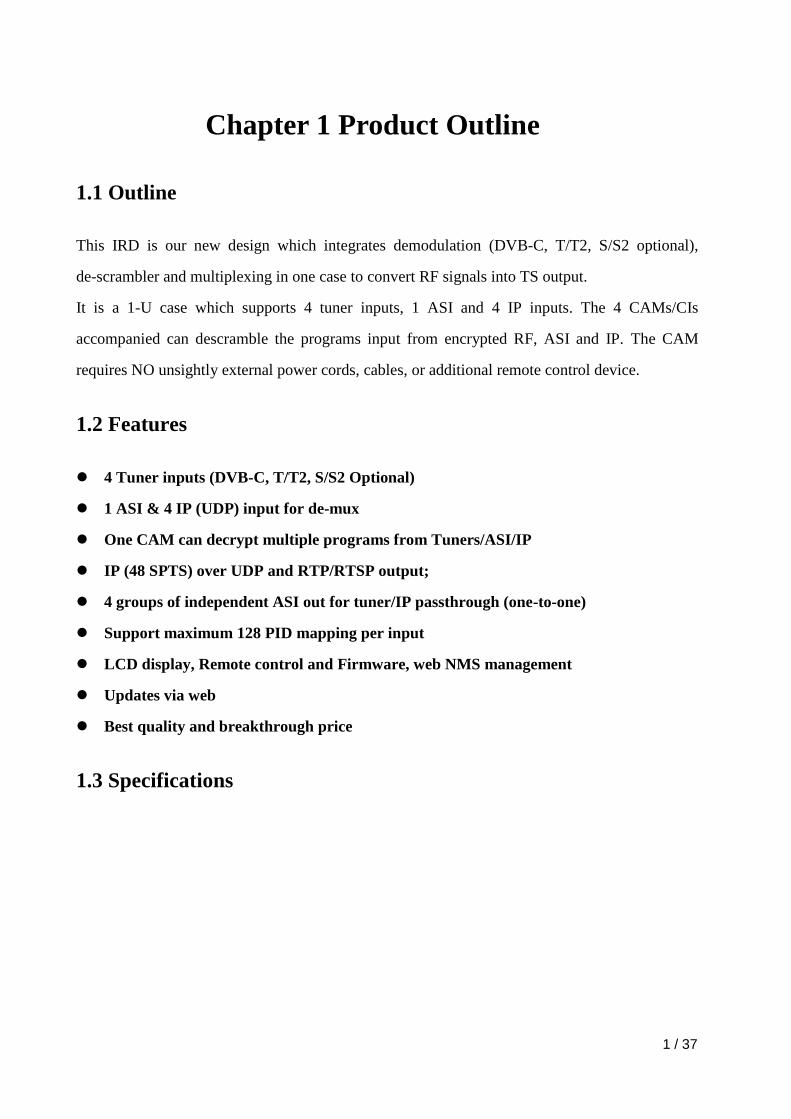
Chapter 1 Product Outline
1.1 Outline
This IRD is our new design which integrates demodulation (DVB-C, T/T2, S/S2 optional),
de-scrambler and multiplexing in one case to convert RF signals into TS output.
It is a 1-U case which supports 4 tuner inputs, 1 ASI and 4 IP inputs. The 4 CAMs/CIs
accompanied can descramble the programs input from encrypted RF, ASI and IP. The CAM
requires NO unsightly external power cords, cables, or additional remote control device.
1.2 Features
4 Tuner inputs (DVB-C, T/T2, S/S2 Optional)
1 ASI & 4 IP (UDP) input for de-mux
One CAM can decrypt multiple programs from Tuners/ASI/IP
IP (48 SPTS) over UDP and RTP/RTSP output;
4 groups of independent ASI out for tuner/IP passthrough (one-to-one)
Support maximum 128 PID mapping per input
LCD display, Remote control and Firmware, web NMS management
Updates via web
Best quality and breakthrough price
1.3 Specifications

IRENIS IGS-700 DVB/IP GATEWAY User’s Manual
2 / 34
Input
4x RF (DVB-C, T/T2, S/S2 optional), F type
1×ASI input for de-mux, BNC interface
4xIP input for de-mux (UDP)
Tuner Section
DVB-C
Standard J.83A(DVB-C), J.83B, J.83C
Input Frequency 47 MHz~860 MHz
Constellation 16/32/64/128/256 QAM
DVB-T/T2
Input Frequency 44MHz ~1002 MHz
Bandwidth 6/7/8 M
DVB-S
Input Frequency 950-2150MHz
Symbol rate 2-45Msps
Signal Strength - 65- -25dBm
Constellation 1/2, 2/3, 3/4, 5/6, 7/8 QPSK
DVB-S2
Input Frequency 950-2150MHz
Symbol rate QPSK 1~45Mbauds;
8PSK 2~30Mbauds
Code rate 1/2, 3/5, 2/3, 3/4, 4/5, 5/6,
8/9, 9/10
Constellation QPSK, 8PSK
Output
IP
48*SPTS over UDP, RTP/RTSP.
1000M Base-T Ethernet interface
(unicast / multicast)
ASI 4 groups BNC interface
System
Local interface LCD + control buttons
Remote management Web NMS Management
Language English
General
Power supply AC 100V~240V
Dimensions 482*400*44.5mm
Weight 3 kgs
Operation temperature 0~45℃

IRENIS IGS-700 DVB/IP GATEWAY User’s Manual
3 / 34
1.4 Principle Chart
IP (48 SPTS) Out
ASI Out 4
4 x CAM/CI
ASI Out 1
ASI Out 2
ASI Out 3
MUX
SAT RF 1
IP 1
SAT RF 2
IP 2
SAT RF 3
IP 3
SAT RF 4
IP 4
ASI
choose 4 channels from all inputs to descramble
CI 1 & 2 are designed to descramble tuner 1/2, ASI or IP 1-4.
CI 3 & 4 are designed to descramble tuner 3/4, ASI or IP 1-4.
1.5 Appearance and description
Front Panel Illustration:
1 LCD Display
2 Indicators Area (Lock 1-4: they light up when the tuner signal are
properly connected. Descram 1-4: they light up when the CI cards
are properly inserted.
3
Up/Down/Left/Right Buttons
Enter Key for confirmation
Menu Key for backward
Lock Key

IRENIS IGS-700 DVB/IP GATEWAY User’s Manual
4 / 34
Rear Panel Illustration
1 CAM/CI Slots 1 & 2 (Applied to descramble tuner 1 & 2, ASI input and
IP input 1 to 4)
2 Tuner Input 1 & 2
3 CAM/CI Slots 3 & 4 (Applied to descramble tuner 3 & 4, ASI input and
IP input 1 to 4)
4 Tuner Input 3 & 4
5 ASI output groups 1-4
6 ASI input port for de-mux
7 NMS Port (connect to PC for device management)
8 DATA Port (for IP stream input & output, 1000M)
9 Power switch/Fuse/Socket/Grounding Wire

IRENIS IGS-700 DVB/IP GATEWAY User’s Manual
5 / 34
Chapter 2 Installation Guide
2.1 Acquisition Check
When user opens the package of the device, it is necessary to check items according to
packing list. Normally it should include the following items:
4-in-1 IRD 1pcs
User’s Manual 1pcs
Tuner Cables (for loop through) 2pcs
Power Cord 1pcs
If any item is missing or mismatching with the list above, please contact our company.
2.2 Installation Preparation
When users install device, please follow the below steps. The details of installation will be
described at the rest part of this chapter. Users can also refer rear panel chart during the
installation.
The main content of this chapter including:
Checking the possible device missing or damage during the transportation
Preparing relevant environment for installation
Installing modulator
Connecting signal cables
Connecting communication port (if it is necessary)
2.2.1 Device's Installation Flow Chart Illustrated as following:
Connecting
Grouding
Wire and
Power
Cord
Acquisition
Check
Fixing
Device
Setting
Parameter
Running
Device
Connecting
Signal Wire
2.2.2 Environment Requirement

IRENIS IGS-700 DVB/IP GATEWAY User’s Manual
6 / 34
Item Requirement
Machine Hall Space
When user installs machine frame array in one machine hall,
the distance between 2 rows of machine frames should be
1.2~1.5m and the distance against wall should be no less
than 0.8m.
Machine Hall Floor
Electric Isolation, Dust Free
Volume resistivity of ground anti-static material:
1X10⁷~1X10
10,Grounding current limiting resistance: 1M
(Floor bearing should be greater than 450Kg/㎡)
Environment
Temperature
5~40℃(sustainable ),0~45℃(short time),
installing air-conditioning is recommended
Relative Humidity 20%~80% sustainable 10%~90% short time
Pressure 86~105KPa
Door & Window Installing rubber strip for sealing door-gaps and dual level
glasses for window
Wall It can be covered with wallpaper, or brightness less paint.
Fire Protection Fire alarm system and extinguisher
Power
Requiring device power, air-conditioning power and lighting
power are independent to each other. Device power requires
AC power 100-240V 50-60Hz. Please carefully check before
running.
2.2.3 Grounding Requirement
All function modules’ good grounding is the basis of reliability and stability of devices.
Also, they are the most important guarantee of lightning arresting and interference
rejection. Therefore, the system must follow this rule.
Coaxial cables outer conductor and isolation layer should keep proper electric
conducting with the metal housing of device.
Grounding conductor must adopt copper conductor in order to reduce high frequency
impedance, and the grounding wire must be as thick and short as possible.
Users should make sure the 2 ends of grounding wire well electric conducted and be

IRENIS IGS-700 DVB/IP GATEWAY User’s Manual
7 / 34
antirust.
It is prohibited to use any other device as part of grounding electric circuit
The area of the conduction between grounding wire and device’s frame should be no
less than 25mm2.
2.2.4 Frame Grounding
All the machine frames should be connected with protective copper strip. The grounding
wire should be as short as possible and avoid circling. The area of the conduction between
grounding wire and grounding strip should be no less than 25mm2.
2.2.5 Device Grounding
Connecting the device’s grounding rod to frame’s grounding pole with copper wire.
2.3 Wire’s Connection
The grounding wire conductive screw is located at the right end of rear panel, and the power
switch, fuse, power supply socket is just beside ,whose order goes like this, power switch is
on the left ,power supply socket is on the right and the fuse is just between them.
Connecting Power Cord
User can insert one end into power supply socket, while insert the other end to AC
power.
Connecting Grounding Wire
When the device solely connects to protective ground, it should adopt independent way,
say, share the same ground with other devices. When the device adopts united way, the
grounding resistance should be smaller than 1Ω.
Caution:
Before connecting power cord to this IRD, user should set the power switch to “OFF”.
2.4 Signal Cable Connection
The signal connections include the connection of input signal cable and the connection of
output signal cable. The details are as follows:

IRENIS IGS-700 DVB/IP GATEWAY User’s Manual
8 / 34
2.4.1 4-in-1 IRD Cables Illustration:
IP Input/output Cable Illustration:
Tuner Cable Illustration:
ASI Input/output Cable Illustration:

IRENIS IGS-700 DVB/IP GATEWAY User’s Manual
9 / 34
Chapter 3 Operation
The front panel of the 4-in-1 IRD is the user-operating interface and the equipment can be
conveniently operated and managed according to the procedures displayed on the LCD:
Keyboard Function Description:
LEFT/RIGHT: Choose and set the parameters.
UP/DOWN: Modify activated parameter or paging up/down when parameter is inactivated.
ENTER: Activate the parameters which need modifications, or confirm the change after
modification.
MENU: Cancel current entered value, resume previous setting; Return to previous menu.
LOCK: Lock the screen/cancel the lock state. After pressing the lock key, the LCD will
display the current configuring state.
3.1 LCD Menu Structure
(See next page :)

IRENIS IGS-700 DVB/IP GATEWAY User’s Manual
10 / 34
Initializing
4 in 1 IRD
Bitrate: 70.865Mbps
1 Status Alarm
Uptime
2 Input Sets 2.1 Tuner DVBS/S2
2.4 Tuner DVBS/S2
3 CI Card 3.1 Card A
3.2 Card B
Tuner Parameters
Mux Program
Satellite frequency
LNB frequency
Symbol rate
LNB voltage
22K
Signal Lock
TS Lock
Parse Program
Select Program
3.1.1 Max Birate
3.1.2 Input TS Mode
3.1.3Card Error Check
3.1.4 Parse Program
3.1.5 Descramble Program
3.1.6 Rom Version
3.1.7 Card Status
3.1.8 Descramble Error
(Same content with ‘Tuner 1’above)
(Same content with ‘Card A’above)
Input IP
Input Port
Multicast
IGMP Snooping
Service IP
2.5: ASI 2.5.1 TS Lock
2.5.2 Parse Program
2.5.3 Select Program
2.6 IP 2.6.1 IP Config
2.6.2 Mux Program TS Lock
Parse Program
Select Program
2.3 Tuner DVBS/S2
2.2 Tuner DVBS/S2
2.7 IP
2.8 IP
2.9 IP
3.3 Card C
3.4 Card D
(Same content with ‘Card A’above)
(Same content with ‘Card A’above)
(Same content with ‘Tuner 1’above)
(Same content with ‘Tuner 1’above)
(Same content with ‘IP 1’above)
(Same content with ‘IP 1’above)
(Same content with ‘IP 1’above)
IRENIS IGS-700 DVB/IP GATEWAY User’s Manual
11 / 34
7 System 7.1 Save Config
7.2 Load Saved CFG
7.3 Factory Reset
7.4 LCD Time-out
7.6 Lock Keyboard
7.7 Product ID
7.8 Language
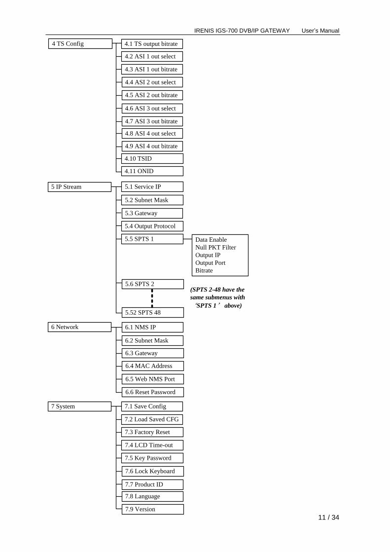
4 TS Config
4.10 TSID
4.11 ONID
4.2 ASI 1 out select
7.5 Key Password
6 Network 6.1 NMS IP
6.2 Subnet Mask
6.3 Gateway
6.4 MAC Address
6.6 Reset Password
6.5 Web NMS Port
4.1 TS output bitrate
5 IP Stream
5.4 Output Protocol
5.5 SPTS 1
5.3 Gateway
Data Enable
Null PKT Filter
Output IP
Output Port
Bitrate
5.1 Service IP
5.2 Subnet Mask
5.6 SPTS 2
5.52 SPTS 48
(SPTS 2-48 have the
same submenus with
‘SPTS 1’ above)
7.9 Version
4.3 ASI 1 out bitrate
4.4 ASI 2 out select
4.5 ASI 2 out bitrate
4.6 ASI 3 out select
4.7 ASI 3 out bitrate
4.8 ASI 4 out select
4.9 ASI 4 out bitrate

IRENIS IGS-700 DVB/IP GATEWAY User’s Manual
12 / 34
3.2 General Setting
Switch on the device and after a few seconds’ initialization, it presents start-up pictures as
below:
4 in 1 IRD: Device’s name
Bitrate: xx.xxx Mbps indicates the current output bitrate.
Press LOCK key on the front panel to enter the main menu. The LCD will display the
following pages where user can configure the parameters for the device:
User could do all the settings according to the 7 directions displayed on the LCD. User can
press UP/DOWN and RIGHT/LEGT buttons to specify menu item, and then press ENTER
to enter the submenus as below:
3.2.1 Status
Alarm: The alarm indicator will turn on if there is no signal inputting or outputting bit rate
overflows. User then can enter this menu to check the error type. Otherwise it shows the
‘system is normal’.
Uptime: It displays the working time duration of the device. It times upon power on.
3.2.2 Input Sets
This IRD supports 4 tuners input, 1 ASI input and 4 IP stream input. Users can enter ‘Input
Start up… Start OK… 4 in 1 IRD
Bitrate: xx.xxx Mbps
1 Status 2 Input Sets
3 CI Card 4 TS Config
Alarm
System is normal
Uptime
1 Day(s) 03:30:02
5 IP Stream 6 Network
7 System
IRENIS IGS-700 DVB/IP GATEWAY User’s Manual
13 / 34
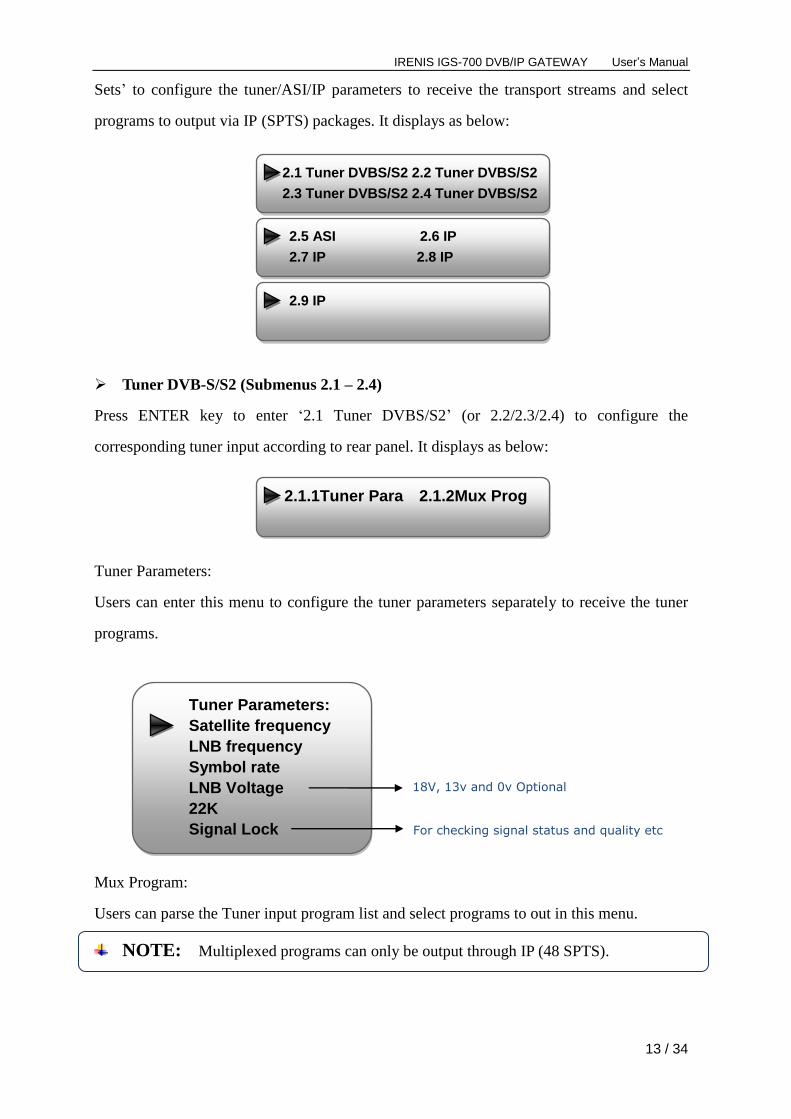
Sets’ to configure the tuner/ASI/IP parameters to receive the transport streams and select
programs to output via IP (SPTS) packages. It displays as below:
Tuner DVB-S/S2 (Submenus 2.1 – 2.4)
Press ENTER key to enter ‘2.1 Tuner DVBS/S2’ (or 2.2/2.3/2.4) to configure the
corresponding tuner input according to rear panel. It displays as below:
Tuner Parameters:
Users can enter this menu to configure the tuner parameters separately to receive the tuner
programs.
Mux Program:
Users can parse the Tuner input program list and select programs to out in this menu.
NOTE: Multiplexed programs can only be output through IP (48 SPTS).
Tuner Parameters:
Satellite frequency
LNB frequency
Symbol rate
LNB Voltage
22K
Signal Lock For checking signal status and quality etc
18V, 13v and 0v Optional
2.1 Tuner DVBS/S2 2.2 Tuner DVBS/S2
2.3 Tuner DVBS/S2 2.4 Tuner DVBS/S2
2.5 ASI 2.6 IP
2.7 IP 2.8 IP
2.9 IP
2.1.1Tuner Para 2.1.2Mux Prog

IRENIS IGS-700 DVB/IP GATEWAY User’s Manual
14 / 34
ASI (Submenus 2.5)
Users can parse ASI input programs and select program(s) to output under this menu. The
operating method is same with what explained above.
IP (Submenus 2.6 – 2.9)
Press ENTER key to enter ‘2.6 IP’, it displays as below:
IP Config:
Users can enter this menu to configure IP parameters according to the IP source to receive
the IP programs.
Mux Program
TS Lock
Parse Program
Select Program
TS Locked
Bitrate: 4.040 Mbps
Searching Program
Get 7 Programs
For reading the input
bitrate
For reading the number
of programs from
Tuner 1 (or 2)
Mux Program (0/7)
1: CCTV 1 X
‘1/7’ represents there are all 7 programs in the list and 1 program has been selected to mux out through ASI.
Mux Program (0/7)
1: CCTV 1 [←]
Mux Program (0/7)
1: CCTV 1 [→]
Mux Program (1/7)
1: CCTV 1 √
Process of selecting programs to
output through front panel:
[←]: to cancel program output;
[→]: to output the program
“√”: a symbol indicating the
corresponding program has been
selected to output;
“X”: a symbol indicating the
corresponding program has not
been selected to output
Press ENTER key
Press RIGHT/LEFT
key to shift arrow
Press ENTER key to
confirm
2.5.1 TS Lock 2.5.2 Parse Program
2.5.3 Select Program
2.6.1 IP Config 2.6.2 Mux Program
Input IP
Input Port
Multicast
IGMP Snooping
Service IP
IRENIS IGS-700 DVB/IP GATEWAY User’s Manual
15 / 34
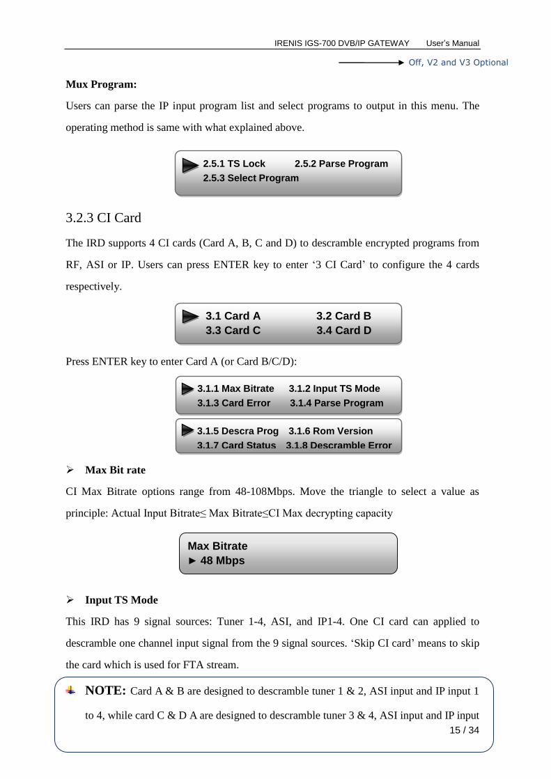
Mux Program:
Users can parse the IP input program list and select programs to output in this menu. The
operating method is same with what explained above.
3.2.3 CI Card
The IRD supports 4 CI cards (Card A, B, C and D) to descramble encrypted programs from
RF, ASI or IP. Users can press ENTER key to enter ‘3 CI Card’ to configure the 4 cards
respectively.
Press ENTER key to enter Card A (or Card B/C/D):
Max Bit rate
CI Max Bitrate options range from 48-108Mbps. Move the triangle to select a value as
principle: Actual Input Bitrate≤ Max Bitrate≤CI Max decrypting capacity
Input TS Mode
This IRD has 9 signal sources: Tuner 1-4, ASI, and IP1-4. One CI card can applied to
descramble one channel input signal from the 9 signal sources. ‘Skip CI card’ means to skip
the card which is used for FTA stream.
NOTE: Card A & B are designed to descramble tuner 1 & 2, ASI input and IP input 1
to 4, while card C & D A are designed to descramble tuner 3 & 4, ASI input and IP input
Off, V2 and V3 Optional
Max Bitrate
► 48 Mbps
2.5.1 TS Lock 2.5.2 Parse Program
2.5.3 Select Program
3.1 Card A 3.2 Card B
3.3 Card C 3.4 Card D
3.1.1 Max Bitrate 3.1.2 Input TS Mode
3.1.3 Card Error 3.1.4 Parse Program
3.1.5 Descra Prog 3.1.6 Rom Version
3.1.7 Card Status 3.1.8 Descramble Error

IRENIS IGS-700 DVB/IP GATEWAY User’s Manual
16 / 34
1 to 4.
Card Error Check
Users can decide whether to enable or disable the card error check function in this menu.
Parse Program
Users can read the quantity of programs parsed from the de-scrambled channel.
Descramble Program
Users can select program(s) from the searched out programs to descramble. The quantity to
be descrambled depends on the CAM/CI performance you apply to.
Rom Version/Card Status/Descramble Error
Users can read the other info about the CI card in the following menus.
Input TS Mode
► Skip CI Card
Tuner 1
Tuner 2
ASI
IP 1
IP 2
IP 3
IP 4
Card Error Check
► Enable
Searching Program
Get 8 Programs
►1 CETV 1 √
2 CCTV 4A X
Rom Version
4.2.4.0
Card Status
Normal
IRENIS IGS-700 DVB/IP GATEWAY User’s Manual
17 / 34
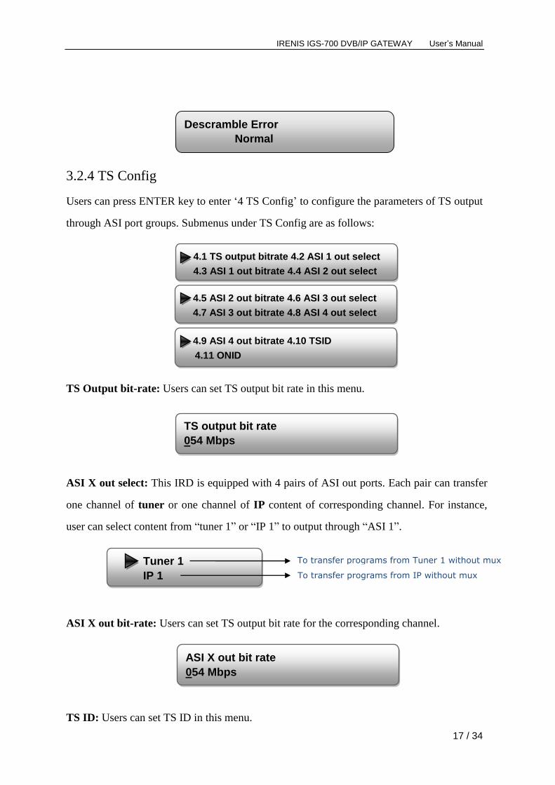
3.2.4 TS Config
Users can press ENTER key to enter ‘4 TS Config’ to configure the parameters of TS output
through ASI port groups. Submenus under TS Config are as follows:
TS Output bit-rate: Users can set TS output bit rate in this menu.
ASI X out select: This IRD is equipped with 4 pairs of ASI out ports. Each pair can transfer
one channel of tuner or one channel of IP content of corresponding channel. For instance,
user can select content from “tuner 1” or “IP 1” to output through “ASI 1”.
ASI X out bit-rate: Users can set TS output bit rate for the corresponding channel.
TS ID: Users can set TS ID in this menu.
Tuner 1
IP 1
To transfer programs from Tuner 1 without mux
Descramble Error
Normal
To transfer programs from IP without mux
4.1 TS output bitrate 4.2 ASI 1 out select
4.3 ASI 1 out bitrate 4.4 ASI 2 out select
4.5 ASI 2 out bitrate 4.6 ASI 3 out select
4.7 ASI 3 out bitrate 4.8 ASI 4 out select
4.9 ASI 4 out bitrate 4.10 TSID
4.11 ONID
TS output bit rate
054 Mbps
ASI X out bit rate
054 Mbps
IRENIS IGS-700 DVB/IP GATEWAY User’s Manual
18 / 34
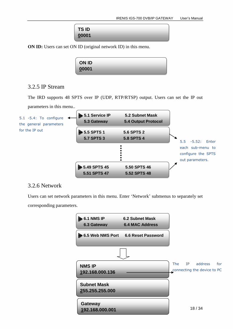
ON ID: Users can set ON ID (original network ID) in this menu.
3.2.5 IP Stream
The IRD supports 48 SPTS over IP (UDP, RTP/RTSP) output. Users can set the IP out
parameters in this menu..
3.2.6 Network
Users can set network parameters in this menu. Enter ‘Network’ submenus to separately set
corresponding parameters.
TS ID
00001
ON ID
00001
NMS IP
192.168.000.136
Subnet Mask
255.255.255.000
Gateway
192.168.000.001
The IP address for
connecting the device to PC
5.1 Service IP 5.2 Subnet Mask
5.3 Gateway 5.4 Output Protocol
5.5 SPTS 1 5.6 SPTS 2
5.7 SPTS 3 5.8 SPTS 4
5.49 SPTS 45 5.50 SPTS 46
5.51 SPTS 47 5.52 SPTS 48
5.1 -5.4: To configure
the general parameters
for the IP out
5.5 -5.52: Enter
each sub-menu to
configure the SPTS
out parameters.
6.1 NMS IP 6.2 Subnet Mask
6.3 Gateway 6.4 MAC Address
6.5 Web NMS Port 6.6 Reset Password
IRENIS IGS-700 DVB/IP GATEWAY User’s Manual
19 / 34
3.2.7 System
Users can set the system parameters in this menu. Enter ‘System’ submenus to separately set
corresponding parameters.
MAC Address
201012345678
Reset Password?
Yes NO
Web NMS Port
00080
Save Configuration?
Yes No
Load Saved CFG?
Yes No
Reset All Sets?
Yes No
LCD Time-out 30 s
Set Password
000000
Choose yes to save settings.
and press ENTER to confirm
Choose yes to restore the
device into the last saved
configuration.
Choose yes to restore the
device into factory’s default
configuration. Press DOWN/UP key to select
a time out for the LCD lighting
duration (5-120 seconds)
To set a 6-digit password for
unlocking the keyboard
Choose Yes to lock the
keyboard, then the keyboard
will be locked and cannot be
applicable. It is required to
7.1 Save Config 7.2 Load Saved CFG
7.3 Factory Reset 7.4 LCD Time-out
7.5 Key Password 7.6 Lock Keyboard
7.7 Product ID 7.8 Language
7.9 Version

IRENIS IGS-700 DVB/IP GATEWAY User’s Manual
20 / 34
Lock Keyboard?
Yes No
xxxxxxxxxxxxxxxxxxxx
xxxxxxxxxxxxxxxxxxxxx
4 in 1 IRD
SW x.xx HW x.xx
User can view the serial number
of this device. It is read-only
and unique
It displays the version
information of this device.
Encoder Modulator: the name
of the device; SW: software
version number; HW:
hardware version number.
Language
English 中文 User can shift the system
language here.
IRENIS IGS-700 DVB/IP GATEWAY User’s Manual
21 / 34
Chapter 4 Web-based NMS Management
In addition to using front buttons to control the device, users can also control and set the
configuration with the web Brower in the PC.
4.1 login
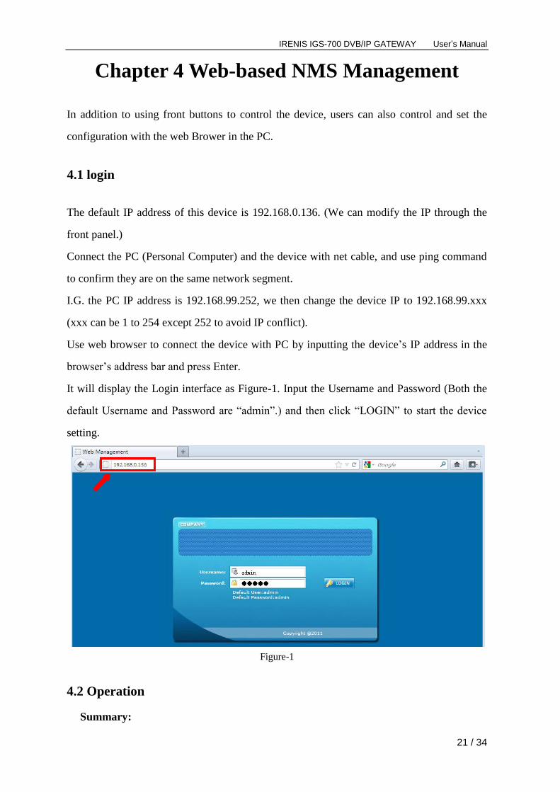
The default IP address of this device is 192.168.0.136. (We can modify the IP through the
front panel.)
Connect the PC (Personal Computer) and the device with net cable, and use ping command
to confirm they are on the same network segment.
I.G. the PC IP address is 192.168.99.252, we then change the device IP to 192.168.99.xxx
(xxx can be 1 to 254 except 252 to avoid IP conflict).
Use web browser to connect the device with PC by inputting the device’s IP address in the
browser’s address bar and press Enter.
It will display the Login interface as Figure-1. Input the Username and Password (Both the
default Username and Password are “admin”.) and then click “LOGIN” to start the device
setting.
Figure-1
4.2 Operation
Summary:

IRENIS IGS-700 DVB/IP GATEWAY User’s Manual
22 / 34
When we confirm the login, it displays the WELCOME interface as Figure-2 where users
can have an overview of the device’s system information and working status.
Figure-2
Parameters → Input 1/2/3/4 (Tuner Input 1-4):
From the menu on left side of the webpage, clicking “Input 1” (or “Input 2/3/4”), it displays
the interface where users can configure the 4 Tuner input parameters separately. (Figure-3)
Figure-3
Configure tuner
parameters in this
area according to
your signal source to
receive programs.
Language
shift area
User can click any item here to enter the
corresponding interface to check
information or set the parameters.
System information
Input information of the 4 satellite signals, ASI
and 4 IP streams.
Green light indicates the corresponding signal is
properly locked. Otherwise the light is red.
Output information of the TS
Click “Apply” button to
apply the input data to
start receive signals.
Tuner signal input 1-4
ASI input
IP signal input 1-4
IRENIS IGS-700 DVB/IP GATEWAY User’s Manual
23 / 34
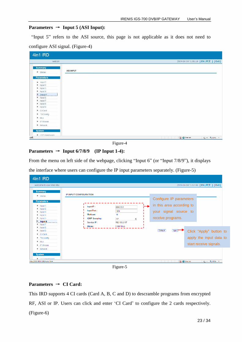
Parameters → Input 5 (ASI Input):
“Input 5” refers to the ASI source, this page is not applicable as it does not need to
configure ASI signal. (Figure-4)
Figure-4
Parameters → Input 6/7/8/9 (IP Input 1-4):
From the menu on left side of the webpage, clicking “Input 6” (or “Input 7/8/9”), it displays
the interface where users can configure the IP input parameters separately. (Figure-5)
Figure-5
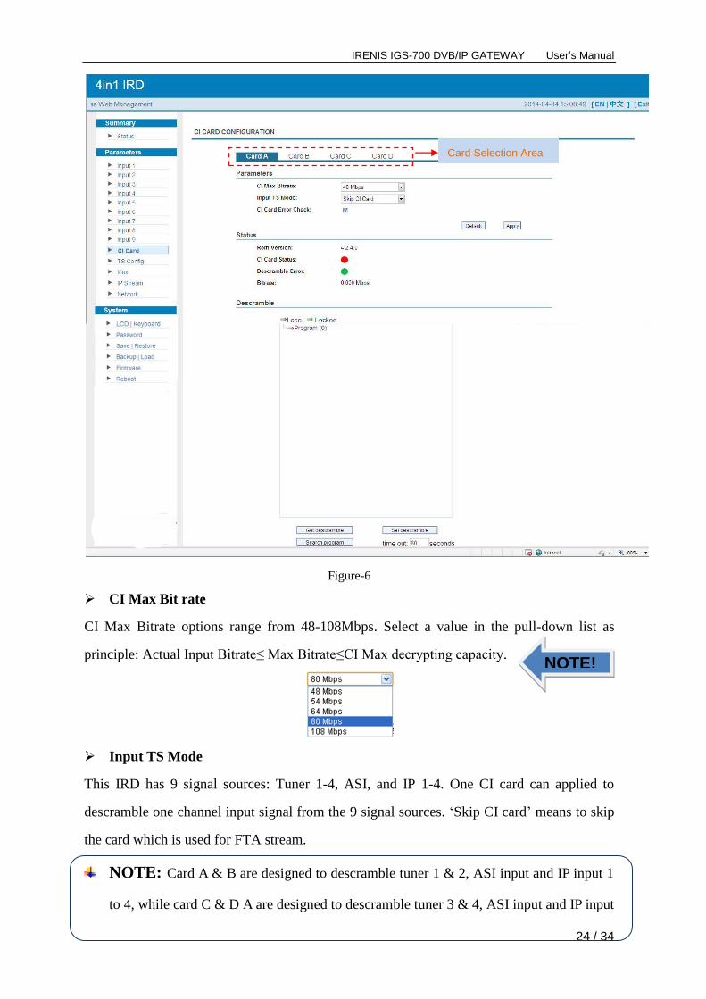
Parameters → CI Card:
This IRD supports 4 CI cards (Card A, B, C and D) to descramble programs from encrypted
RF, ASI or IP. Users can click and enter ‘CI Card’ to configure the 2 cards respectively.
(Figure-6)
Click “Apply” button to
apply the input data to
start receive signals.
Configure IP parameters
in this area according to
your signal source to
receive programs.
IRENIS IGS-700 DVB/IP GATEWAY User’s Manual
24 / 34
Figure-6
CI Max Bit rate
CI Max Bitrate options range from 48-108Mbps. Select a value in the pull-down list as
principle: Actual Input Bitrate≤ Max Bitrate≤CI Max decrypting capacity.
Input TS Mode
This IRD has 9 signal sources: Tuner 1-4, ASI, and IP 1-4. One CI card can applied to
descramble one channel input signal from the 9 signal sources. ‘Skip CI card’ means to skip
the card which is used for FTA stream.
NOTE: Card A & B are designed to descramble tuner 1 & 2, ASI input and IP input 1
to 4, while card C & D A are designed to descramble tuner 3 & 4, ASI input and IP input
NOTE!
Card Selection Area
IRENIS IGS-700 DVB/IP GATEWAY User’s Manual
25 / 34
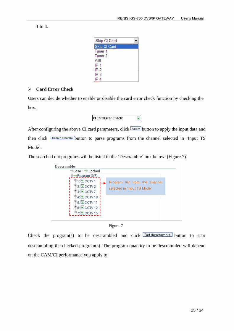
1 to 4.
Card Error Check
Users can decide whether to enable or disable the card error check function by checking the
box.
After configuring the above CI card parameters, click button to apply the input data and
then click button to parse programs from the channel selected in ‘Input TS
Mode’.
The searched out programs will be listed in the ‘Descramble’ box below: (Figure 7)
Figure-7
Check the program(s) to be descrambled and click button to start
descrambling the checked program(s). The program quantity to be descrambled will depend
on the CAM/CI performance you apply to.
Program list from the channel
selected in ‘Input TS Mode’

IRENIS IGS-700 DVB/IP GATEWAY User’s Manual
26 / 34
Parameters → TS Config:
From the menu on left side of the webpage, clicking “TS Config”, it displays the interface
where users can configure the parameters of TS output through ASI port groups. (Figure-8)
Figure-8
ASI X out select: This IRD is equipped with 4 pairs of ASI out ports. Each pair can transfer
one channel of tuner or one channel of IP content of corresponding channel. For instance,
user can select content from “tuner 1” or “IP 1” to output through “ASI 1”.
ASI X out bit-rate: Users can set TS output bit rate for the corresponding channel.
After finishing the configuration, click to confirm.
Number before slash indicates the programs which have been descrambled.
Number behind slash indicates the whole programs from the selected channel.
Users can also read the program information by clicking ‘+’ symbol.
Configure TS ID and ON ID here for the output stream.
IRENIS IGS-700 DVB/IP GATEWAY User’s Manual
27 / 34
Parameters → Mux:
From the menu on left side of the webpage, clicking “Mux”, it displays the interface where
users can configure the programs to be multiplexed. (Figure-9)
NOTE: Programs selected to multiplex can only output through the 48 SPTS.
Figure-9
Configure ‘Input Area’ and ‘Output Area’ with buttons in ‘Operation Area’. Instructions are
as below:
: To enable/disable the PID remapping
To refresh the input program information
To refresh the output program information
Select one input program first and click this button to transfer the selected
program to the right box to output.
Similarly, user can cancel the multiplexed programs from the right box.
To select all the input programs
To select all the output programs
To parse programs time limitation of parsing input programs
Program Modification:
The multiplexed program information can be modified by clicking the program in the
Input Area Output Area
Operation Area

IRENIS IGS-700 DVB/IP GATEWAY User’s Manual
28 / 34
‘output’ area. For example, when clicking , it triggers a dialog box (Figure 10)
where users can input new information.
Figure-10
Input new data and click ‘Save’ button at last to confirm the modification.
Parameters → IP Stream:
This unit supports TS output in IP (48 SPTS). Click “IP Stream” and it displays the
interface where users can configure the SPTS out parameters. (Figure-13)
Figure-13
NOTE!
This device supports 48
SPTS IP out. Users can
enable and select the
program output via SPTS
here.

IRENIS IGS-700 DVB/IP GATEWAY User’s Manual
29 / 34
Parameters → Network:
From the menu on left side of the webpage, clicking “Network”, it will display the screen
as Figure-14 where to configure the network parameters for the device.
Figure-14
System → LCD/Keyboard:
From the menu on left side of the webpage, clicking “LCD/Keyboard”, it will display the
screen as Figure-15 where to control the device’s front panel.
Figure-15
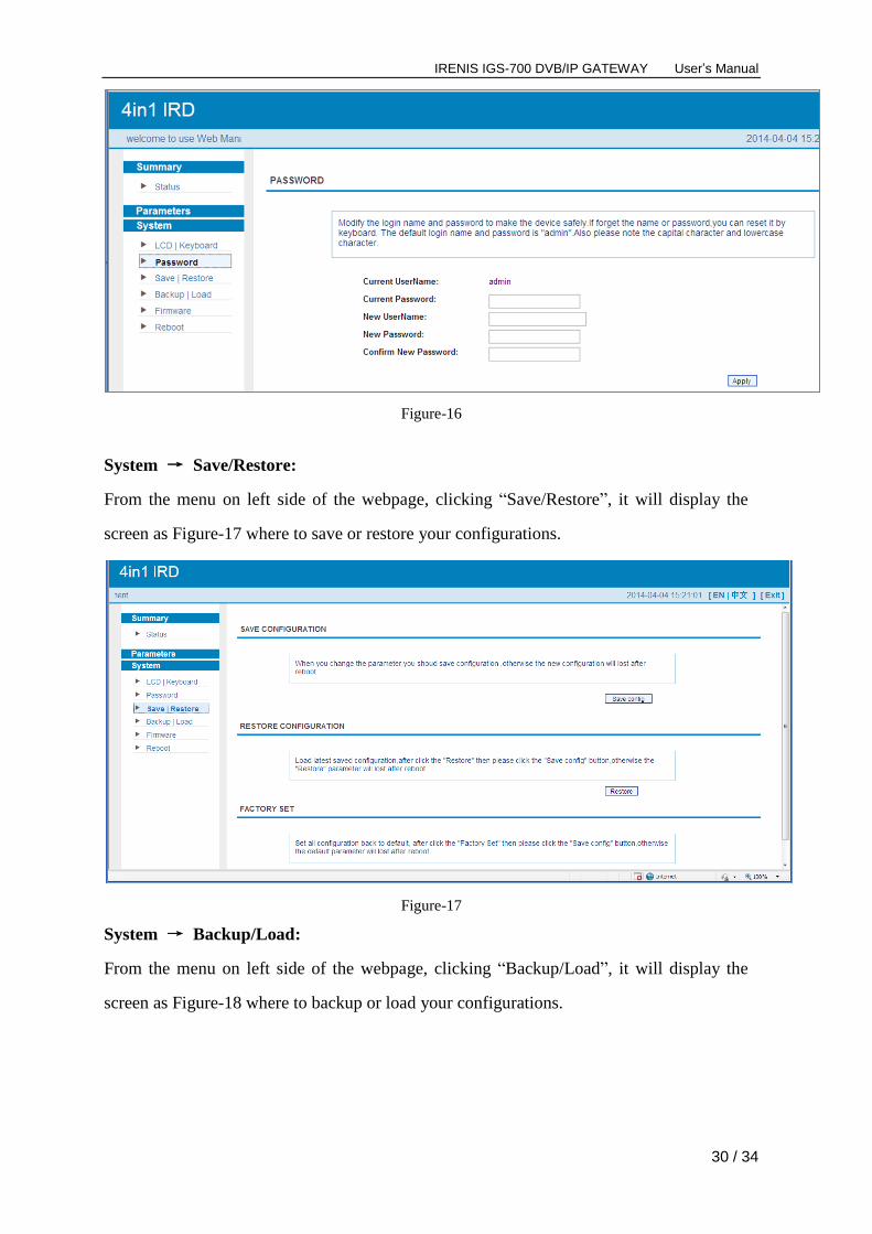
System → Password:
From the menu on left side of the webpage, clicking “Password”, it will display the screen
as Figure-16 where to set the login account and password for the web NMS.
IRENIS IGS-700 DVB/IP GATEWAY User’s Manual
30 / 34
Figure-16
System → Save/Restore:
From the menu on left side of the webpage, clicking “Save/Restore”, it will display the
screen as Figure-17 where to save or restore your configurations.
Figure-17
System → Backup/Load:
From the menu on left side of the webpage, clicking “Backup/Load”, it will display the
screen as Figure-18 where to backup or load your configurations.

IRENIS IGS-700 DVB/IP GATEWAY User’s Manual
31 / 34
Figure-18
System → Firmware:
From the menu on left side of the webpage, clicking “Firmware”, it will display the screen
as Figure-19 where to update firmware for the device.
Figure-19
System → Reboot:
From the menu on left side of the webpage, clicking “Reboot”, it will display the screen as
Figure-20 where to restart the device manually.

IRENIS IGS-700 DVB/IP GATEWAY User’s Manual
32 / 34
Figure-20

IRENIS IGS-700 DVB/IP GATEWAY User’s Manual
33 / 34
Chapter 5 Troubleshooting
ISO9001 quality assurance system has been approved by CQC organization. For guarantee the products’
quality, reliability and stability. All our products have been passed the testing and inspection before ship
out factory. The testing and inspection scheme already covers all the Optical, Electronic and Mechanical
criteria which have been published by us. To prevent potential hazard, please strictly follow the operation
conditions.
Prevention Measure
Installing the device at the place in which environment temperature between 0 to 45 °C
Making sure good ventilation for the heat-sink on the rear panel and other heat-sink bores if
necessary
Checking the input AC voltage within the power supply working range and the connection is correct
before switching on device
Checking the RF output level varies within tolerant range if it is necessary
Checking all signal cables have been properly connected
Frequently switching on/off device is prohibited; the interval between every switching on/off must
greater than 10 seconds.
Conditions need to unplug power cord
Power cord or socket damaged.
Any liquid flowed into device.
Any stuff causes circuit short
Device in damp environment
Device was suffered from physical damage
Longtime idle.
After switching on and restoring to factory setting, device still cannot work properly.
Maintenance needed

IRENIS IGS-700 DVB/IP GATEWAY User’s Manual
34 / 34
Chapter 6 Packing List
4 in 1 IRD 1pcs
User’s Manual 1pcs
RF Cables 2pcs
Power Cord 1pcs