iridium-next star tracker thermal design: lessons learned
TRANSCRIPT

44th International Conference on Environmental Systems ICES-2014- 171 13-17 July 2014, Tucson, Arizona
IRIDIUM-NEXT Star Tracker Thermal Design: lessons
learned and learning curve in a small series production
M. Fabbri1 and M. Molina
2
Università degli studi di Firenze- Selex ES
IRIDIUM-NEXT is the second generation of a global satellite constellation, composed by
66 cross-linked LEO satellites covering the whole globe. The attitude determination for each
satellite is assigned to one MHSTR (MultiHead Star Tracker) consisting of 3 Star Trackers
(STR). The prime contractor is Thales Alenia Space and, in this context, Selex ES has the
full responsibility of the Star Tracker procurement. The launch of the first satellite is
expected in 2015. Given the thermal insulation requirements between the STRs and the S/C
(with a conductance lower than 0.1 W/K), the STR design is strongly affected in both the
thermal and the structural aspects. The thermal detailed design of the sensor has been
focused on:
- Characterization and development of the thermal paths in order to keep the sensor
temperature lower than 15°C
- Optimization of the coatings
The thermal design has been numerically analyzed and verified through experimental
tests to validate the model. The paper describes the development of both the thermal and
geometrical detailed mathematical models, the execution of the thermal balance test (TBT)
and the following correlation activity for the TMM. The prediction of the expected in-orbit
performances are also reported. Reference is made to the optimization of the recurring
testing activities, in light of the small series (250 units) production launched.
Nomenclature
= cross section area
= distance between nodes
= heat transfer factor between node and node
= thermal conductance coefficient
= thermal resistance between node and node
= emissivity of surface i
= equivalent radiative coupling ( )
= absorptivity of surface j
= view factor between surface i and j
= area of surface i
= radiative conductor between node i and node j
= equivalent conductivity (
σ = Stephan Boltzman constant
= temperature difference
= initial temperature difference
= time (s)
= time costant
1 PhD candidate, Department of Industrial Engineering, Via S. Marta 3 – 50100 Firenze FI (Italy).
2 Chief Technical Officer, LoB Space, Viale Europa - 20014 Nerviano MI (Italy)
.
International Conference on Environmental Systems
2
I. Introduction
RIDIUM-NEXT is the second generation of global cross-linked LEO satellites. The constellation consists of 66
orbiting satellites in LEO orbit, able to cover 100% of the globe, to which 6 spare satellites are added in parking
orbit and 9 spare satellites on ground.
The attitude determination for each satellite is assigned to one MHSTR (MultiHead Star Tracker) consisting of 3
Optical Heads (OH). Each OH is made by one Star Tracker (STR), able to perform an attitude determination by
acquiring and tracking catalogued stars.
Each satellite is equipped with a redundant system, designed to allow the attitude determination even in case of
failure or obscuration of one or more optical heads (OH). This is made possible thanks to a different mounting
inclination of each STR, in order to allow to each OH to cover a different sector of the sky.
The purpose of this article is to describe the stages of development and validation of the thermal mathematical
model of the STR, and the key points of the design concept.
The major challenge in the design and development of STR for the mission IRIDIUM-NEXT, lies in the
definition of the parameters for the thermal control of the detector. In fact it is necessary that this maintains a stable
temperature in order to operate in conditions of high performance.
The paper describes, first of all, the boundary condition, in terms of performance requirements and survivability
conditions, established by the prime contractor. This is followed by the detailed description of both geometrical and
thermal models, developed for predicting the behaviour of the STR during in-flight condition and on ground tests.
Then the description of the Thermal Balance Test is reported, followed by the presentation of the correlation process
of the thermal model.
II. IRIDIUM-OH Star Tracker
The IRIDIUM-NEXT boundary conditions, in accordance with the mission and the prime contractor’s
requirements, are reported below:
- Mounting interface on the satellite,
achieved using 4 M5 screws, thermally
insulated (conductively) from the S/C
itself
- Accommodation: internal to the satellite
inside a cavity of the S/C (Figure 2),
surrounded by black MLI covering the
cavity itself
- Minimum temperature of the internal part
of the S/C, during operative condition = -
30°C
- Maximum temperature of the internal part
of the S/C, during operative condition =
+55°C
- Sun heat flux (1AU)= 1418 W/m²
- View factor with Space = 0.9
The Housing of the STR is made of
aluminium, internally alodined (in order to protect
the structure preventing the corrosion) and black
painted on the external surfaces, to be well
radiative coupled with the surrounding S/C environment. The need of a good radiative thermal link with the
environment ensue from the requirement of the conductive insulation from the spacecraft, hence in order to have a
path to dissipate thermal power.
I
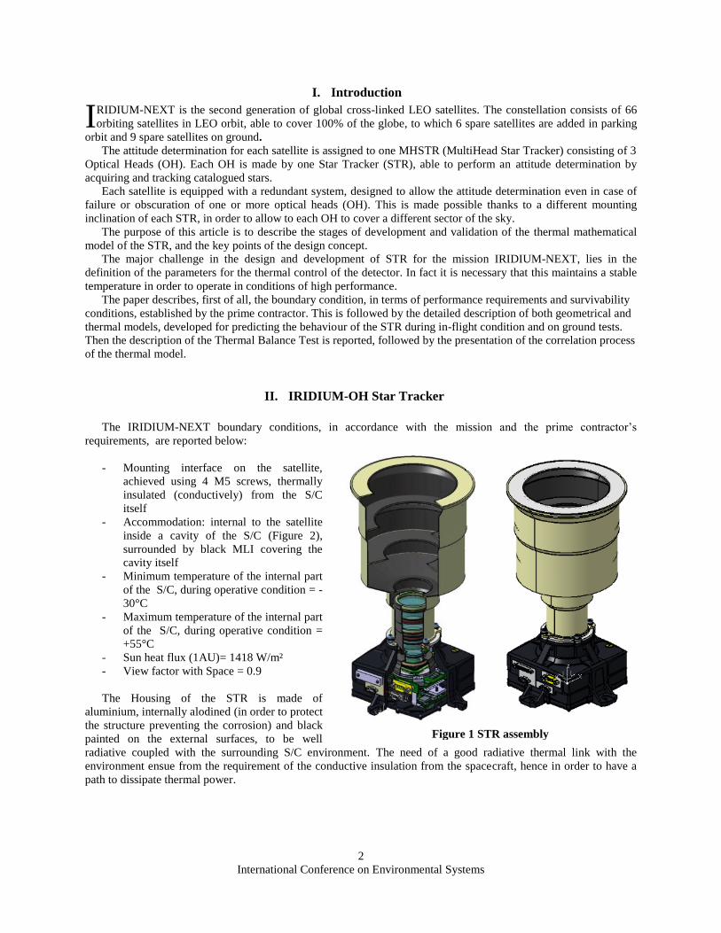
Figure 1 STR assembly
International Conference on Environmental Systems
3
The STR has an overall mass of about 1500g, splitted as follows:
- Optical assembly = 340g
- Focal Plane assembly = 200g
- Main PCB = 250g
- Structure = 290g
- Baffle = 320g
- Miscellaneous (bolts etc..) = 50g
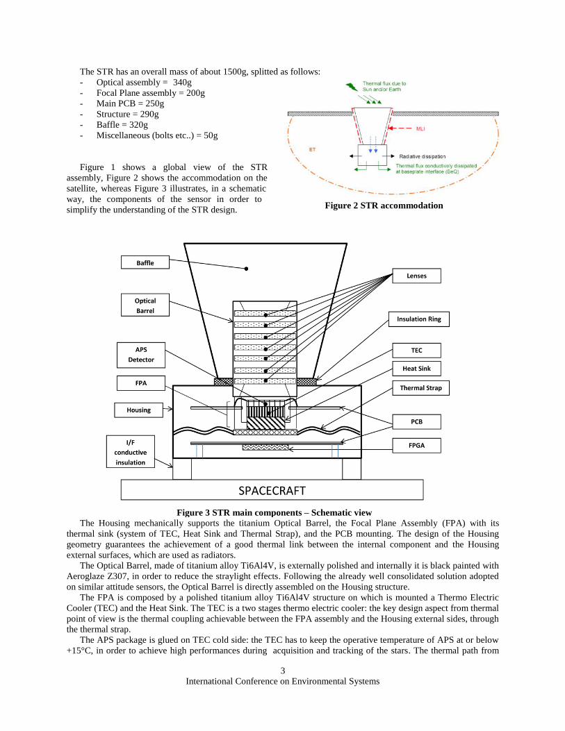
Figure 1 shows a global view of the STR
assembly, Figure 2 shows the accommodation on the
satellite, whereas Figure 3 illustrates, in a schematic
way, the components of the sensor in order to
simplify the understanding of the STR design.
The Housing mechanically supports the titanium Optical Barrel, the Focal Plane Assembly (FPA) with its
thermal sink (system of TEC, Heat Sink and Thermal Strap), and the PCB mounting. The design of the Housing
geometry guarantees the achievement of a good thermal link between the internal component and the Housing
external surfaces, which are used as radiators.
The Optical Barrel, made of titanium alloy Ti6Al4V, is externally polished and internally it is black painted with
Aeroglaze Z307, in order to reduce the straylight effects. Following the already well consolidated solution adopted
on similar attitude sensors, the Optical Barrel is directly assembled on the Housing structure.
The FPA is composed by a polished titanium alloy Ti6Al4V structure on which is mounted a Thermo Electric
Cooler (TEC) and the Heat Sink. The TEC is a two stages thermo electric cooler: the key design aspect from thermal
point of view is the thermal coupling achievable between the FPA assembly and the Housing external sides, through
the thermal strap.
The APS package is glued on TEC cold side: the TEC has to keep the operative temperature of APS at or below
+15°C, in order to achieve high performances during acquisition and tracking of the stars. The thermal path from
Figure 2 STR accommodation
Figure 3 STR main components – Schematic view
International Conference on Environmental Systems
4
the TEC hot side is composed by a copper thermal plate (heat sink), connected with an aluminium thermal strap
which transfers heat towards the Housing. The heat sink connection with the thermal strap is obtained by means of 3
screws that ensure the required thermal coupling via a good metal to metal contact. The electronic assembly is
composed by two PCB and the relevant harness; the PCB cards are polyimide HI-3003 multilayered boards: copper
layers and polyamide laminated. The digital PCB card is mounted parallel to the Housing base and mechanically
fixed on its edges by means of screws. Internal thermal copper tracks have been foreseen on PCB card to remove the
heat which is dissipated by electronics components placed on the card, in particular from FPGA and voltage
regulator, which have the higher heat dissipation. The PCB internal copper tracks reach the external edge of the
card, where a good thermal contact between cards and Housing is obtained by screws.
The STR is also equipped with a Baffle in order to reduce the optical disturbances due to light sources in space.
The Baffle is made of aluminium alloy and it is externally alodined and internally black painted with Electrodag502,
in order to reduce the straylight effects.
The thermal concept is based on the trade-off between the achievement of good radiative coupling with the
surrounding environment and, at the same time, the best insulation from radiative solar flux (Figure 2) and from the
infrared emissions of high temperature surfaces that have a view factor with the STR. The criticality from the
thermal point of view are stressed by the small size of the overall dimension sensor, which has a longitudinal
envelope of 300mm and a transversal envelope of 164mm. Smaller dimensions imply a reduction in the extension of
the external surfaces, with consequent limitation on the radiative emissions of heat fluxes. The main objective of the
thermal design of the STR is to maximize the capability of heat dissipation of the sensor, minimizing both the
absorption of external flows and the internal electronic power consumption. The critical components of the thermal
design are:
- Baffle, main responsible of radiative coupling with the space environment
- Housing, which represent the ‘cold sink’ in the conductance chain starting from the APS detector
- TEC, which is in charge with the thermal control of the APS detector
After a series of simulation and sensitivity analysis, a design optimum was found: in order to limit the heat flux
from the baffle to the housing, these components are thermally decoupled by means of a thermal insulation ring.
Similarly, in order to limit the orbital fluxes and thus to reduce the orbital heat loads absorbed by the STR, the top
part of the baffle is polished metal.
III. IRIDIUM-OH STR Mathematical Model
In order to characterize the thermal behavior of the sensor, a thermal mathematical model has been developed,
using ESATAN-TMS: a thermal mathematical model and a geometric model were used.
In the following paragraphs a detailed description of both models is provided.
A. Thermal Mathematical Model
The model was built using the lumped parameter approach, representing the simplest and most convenient
method that can be used to solve transient conduction problems.
The applicability of the lumped parameter approach is confirmed by estimation of the Biot (1) number, as
follows:
(1)
where
- = radiative coefficient
- = characteristic lenght of the system
- = thermal conductivity of the system
International Conference on Environmental Systems
5
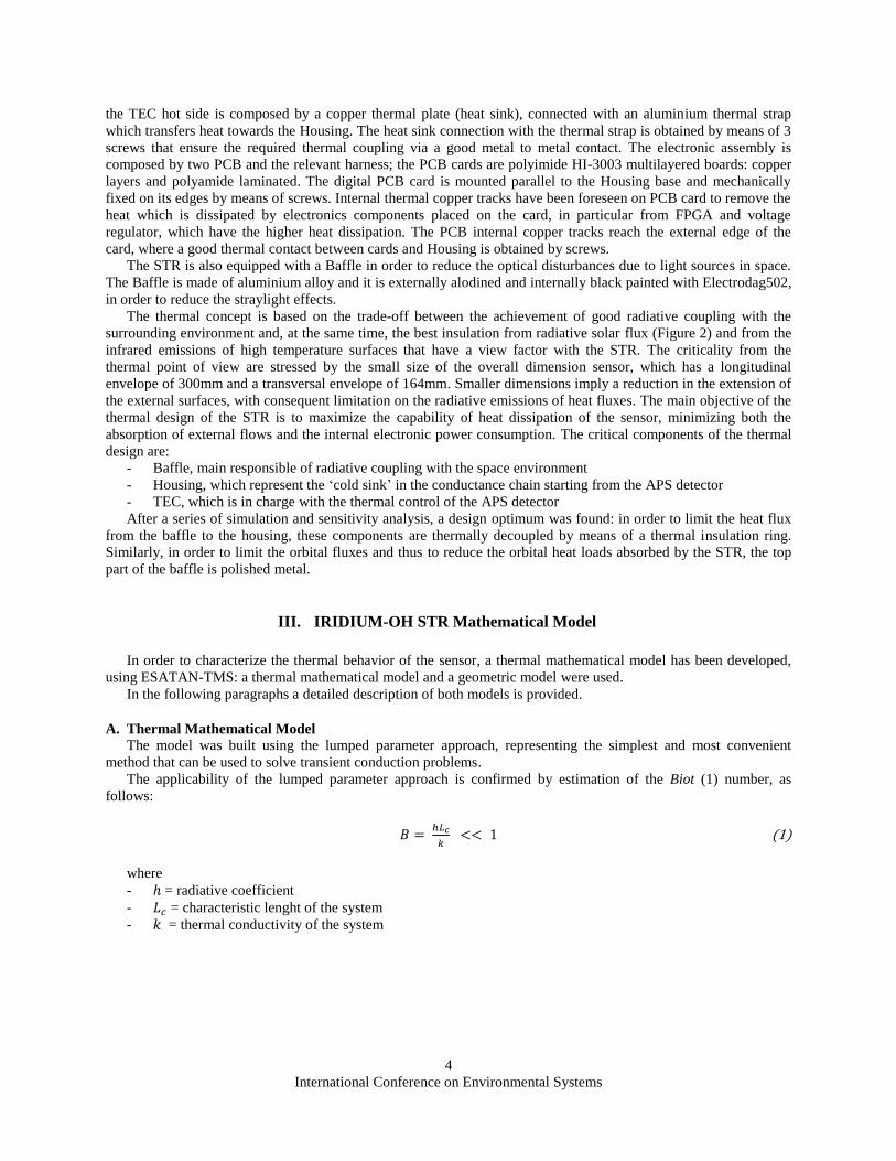
Figure 4 STR elements – Nodal breakdown
During the numerical modeling of the STR, 92 thermal nodes have been identified, each corresponding to a portion
of the STR. The chosen nodal breakdown represents the trade-off between computational costs of the solution and
the ability to describe in sufficient detail all the thermal
gradients. In order to describe the thermal gradients both
radial and circumferential , the STR was divided
circumferentially in 4 sections. In Figure 4 a portion of the
nodal breakdown of the Housing, the Baffle and the Optical
Barrel, is represented.
Figure 5 shows the heat flows determining the temperature
gradients over the STR during orbit operations.
The conductive linear couplings (GL) were calculated
starting from the thermal properties of the materials used
and the
geometry
of each
thermal node. Among all the conductances, the total
conductance between STR and S/C represent a constraint
for the design, and the specific figure requested by the
prime is 0.1 W/K.
As operational blocks of the TMM, the control
subroutines of the TEC have been implemented. The
subroutine were based on the thermo electric cooler
characteristic curves.
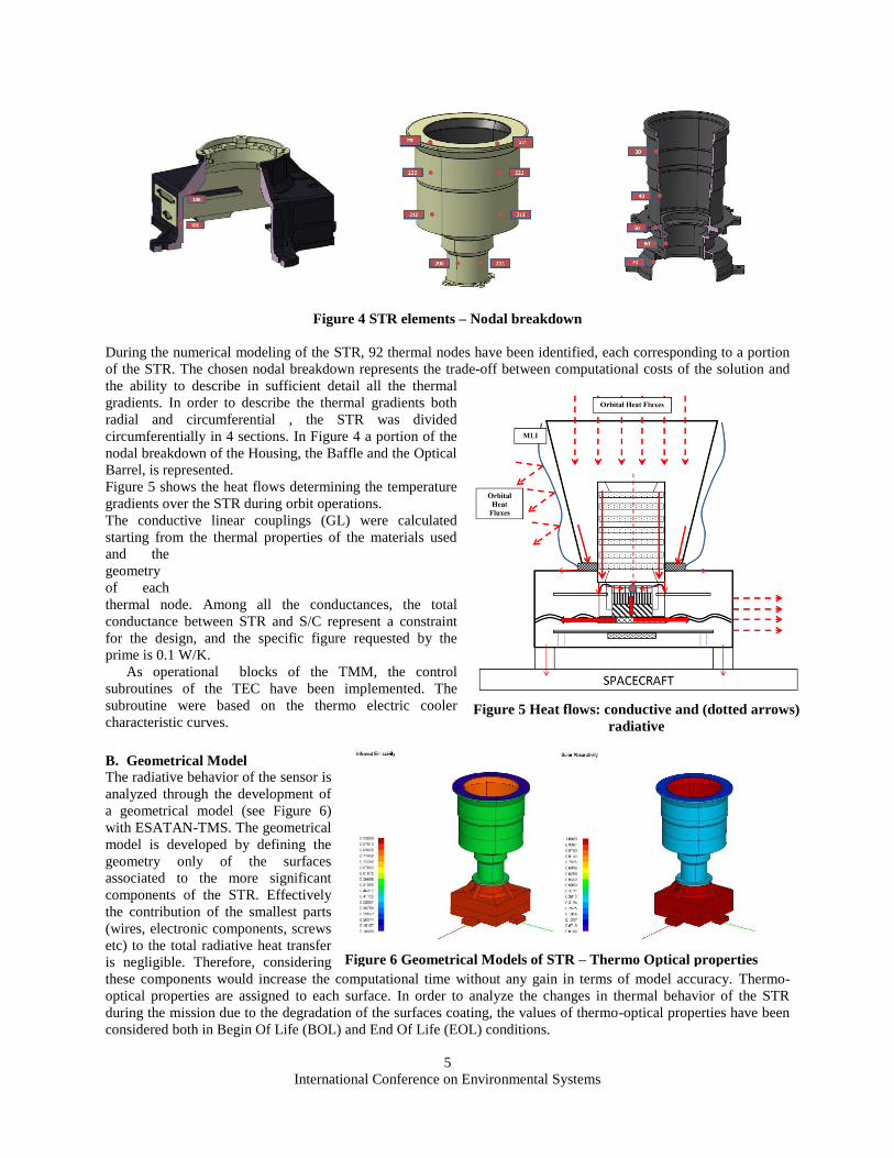
B. Geometrical Model
The radiative behavior of the sensor is
analyzed through the development of
a geometrical model (see Figure 6)
with ESATAN-TMS. The geometrical
model is developed by defining the
geometry only of the surfaces
associated to the more significant
components of the STR. Effectively
the contribution of the smallest parts
(wires, electronic components, screws
etc) to the total radiative heat transfer
is negligible. Therefore, considering
these components would increase the computational time without any gain in terms of model accuracy. Thermo-
optical properties are assigned to each surface. In order to analyze the changes in thermal behavior of the STR
during the mission due to the degradation of the surfaces coating, the values of thermo-optical properties have been
considered both in Begin Of Life (BOL) and End Of Life (EOL) conditions.
Figure 6 Geometrical Models of STR – Thermo Optical properties
Figure 5 Heat flows: conductive and (dotted arrows)
radiative

International Conference on Environmental Systems
6
The calculation of view factors and direct heat fluxes are performed in ESATAN-TMS with the Monte Carlo ray
tracing method (MCRT). The radiative couplings (GR) are computed by means of equation (3)
(2)
Specific coatings allow to obtain specific radiative couplings. In particular, in greater detail, in order to limit the
maximum temperature reached by the electronic components during the operational condition, it is necessary to
minimize the radiative coupling with the Housing. In fact this is heated by the conductive dissipation through the
thermal strap due to the TEC and by the solar fluxes, impinging on the baffle. At the same time, in order to limit the
maximum temperature, it is necessary to provide for a good radiative coupling between the outer wall of the
Housing and the S/C (temperature controlled), and between the baffle and the Space. From a radiative point of view,
the Baffle is hence a critical component. For optical reasons the baffle must be black internally. This coating
(Electrodag 502), having high both α and ε, causes high emission towards the cold space and at the same time a
higher absorption of solar radiation with the consequent increase in temperature during drect Sun illumination.
To obtain a decrease of the total absorptivity of the baffle, this was externally covered by MLI and polished on the
apical surface. This solution allows to achieve a decrease in affective absorptance and results in a decrease in the
total solar flux absorbed by the whole baffle of 21% (from 6.8W to 5.4W), in comparison with a Baffle externally
alodined, and considering the average flux during a polar Low Earth Orbit.
The GR describing the radiative coupling between Baffle and MLI, are calculated with equation (3), as specified
by the requirements:
)( 44
ieieqieieq TTATTAB (3)
where:
is the MLI external foil temperature [K]
is the MLI internal foil temperature [K]
To minimize the coupling between the electronic components and the Housing, this was internally covered with
Alodine 1200.
C. On-Orbit Run Results
Through the thermal and geometrical models described above, the worst orbital operating conditions for the STR
have been identified. Both steady state and transient analysis were performed. The steady state analysis were
performed considering steady environment temperature and an average Sun heat flux: this type of analysis has been
run considering both low and high temperature, and operating non-operating STR conditions, as specified in the
satellite-provided
requirements.
In addition, in order to
suitably characterize the STR
in-orbit behaviour, three type
of transient analysis were
performed:
- survivability analysis
of the STR during a
continuous Sun
illumination, with the
Sun inside the FoV
- analysis of the
behavior in the worst
case of loss of satellite
attitude, considering
the parameters of time,
inclination of the Sun
and boundary
conditions as reported
0
10
20
30
40
50
60
70
80
180 280 380 480 580 680 780 880 980
Tem
pera
ture
[ C
]
Orbit angular position [deg]
STR temperature distribution
Baffle PCB Focal Plane Housing External Lens APS TEC hot side
Figure 7 Temperature distribution over STR - Transient analysis results
International Conference on Environmental Systems
7
in requirements
- analysis of the worst operating Earth orbit, considering the maximum Sun heat flux
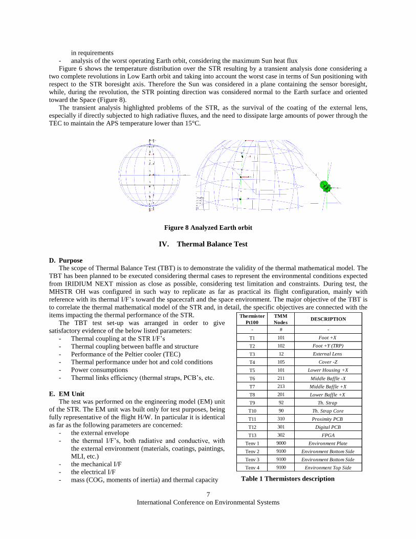
Figure 6 shows the temperature distribution over the STR resulting by a transient analysis done considering a
two complete revolutions in Low Earth orbit and taking into account the worst case in terms of Sun positioning with
respect to the STR boresight axis. Therefore the Sun was considered in a plane containing the sensor boresight,
while, during the revolution, the STR pointing direction was considered normal to the Earth surface and oriented
toward the Space (Figure 8).
The transient analysis highlighted problems of the STR, as the survival of the coating of the external lens,
especially if directly subjected to high radiative fluxes, and the need to dissipate large amounts of power through the
TEC to maintain the APS temperature lower than 15°C.
Figure 8 Analyzed Earth orbit
IV. Thermal Balance Test
D. Purpose
The scope of Thermal Balance Test (TBT) is to demonstrate the validity of the thermal mathematical model. The
TBT has been planned to be executed considering thermal cases to represent the environmental conditions expected
from IRIDIUM NEXT mission as close as possible, considering test limitation and constraints. During test, the
MHSTR OH was configured in such way to replicate as far as practical its flight configuration, mainly with
reference with its thermal I/F’s toward the spacecraft and the space environment. The major objective of the TBT is
to correlate the thermal mathematical model of the STR and, in detail, the specific objectives are connected with the
items impacting the thermal performance of the STR.
The TBT test set-up was arranged in order to give
satisfactory evidence of the below listed parameters:
- Thermal coupling at the STR I/F’s
- Thermal coupling between baffle and structure
- Performance of the Peltier cooler (TEC)
- Thermal performance under hot and cold conditions
- Power consumptions
- Thermal links efficiency (thermal straps, PCB’s, etc.
E. EM Unit
The test was performed on the engineering model (EM) unit
of the STR. The EM unit was built only for test purposes, being
fully representative of the flight H/W. In particular it is identical
as far as the following parameters are concerned:
- the external envelope
- the thermal I/F’s, both radiative and conductive, with
the external environment (materials, coatings, paintings,
MLI, etc.)
- the mechanical I/F
- the electrical I/F
- mass (COG, moments of inertia) and thermal capacity
Thermistor
Pt100
TMM
NodesDESCRIPTION
- # -
T1 101 Foot +X
T2 102 Foot +Y (TRP)
T3 12 External Lens
T4 105 Cover -Z
T5 101 Lower Housing +X
T6 211 Middle Baffle -X
T7 213 Middle Baffle +X
T8 201 Lower Baffle +X
T9 92 Th. Strap
T10 90 Th. Strap Core
T11 310 Proximity PCB
T12 301 Digital PCB
T13 302 FPGA
Tenv 1 9000 Environment Plate
Tenv 2 9100 Environment Bottom Side
Tenv 3 9100 Environment Bottom Side
Tenv 4 9100 Environment Top Side
Table 1 Thermistors description

International Conference on Environmental Systems
8
- the internal H/W (at least all items contributing to thermal characterization of the TMM, e.g. as regards
thermal capacity, power dissipation, etc.)
- the power consumptions
The EM unit was equipped with a total of 13 thermistors (Pt100), 8 of which mounted externally and 5
internally. Special attention was paid to the characterization of the critical components identified through the
numerical analysis previously carried out. In detail:
- Conductive coupling between Housing and Baffle
- Conductive coupling between Thermal Strap and Housing
- External lens radiative and conductive coupling with environment
In Table 1, Figure 9, Figure 10, Figure 11 and Figure 12 the thermistors positioning is represented.
A heater was mounted on the baffle of
the STR, in order to have the possibility
of increasing the temperature of the
baffle through the application of a known
electrical power. This allows to
characterize the GL between the Baffle
and the Housing. In addition, the EM unit
was mounted reproducing the insulation
interface with the satellite as mission
requirements. The use of additional test
items on EM (e.g. test heaters for
simulation) did not affect the above
discussed representativity of the EM.
Figure 9 Thermistor mounted on the equipment simulating S/C
cavity
Figure 10 External and Internal thermistors mounting position

International Conference on Environmental Systems
9
F. Test Set-Up
The test hardware is composed of a
thermal vacuum chamber (TVC), and of
an equipment reproducing the radiative
environment in space. The TVC is
equipped with a dedicated thermal
control system, able to set the
temperature of the chamber within a
tolerance of ±1°C. The maximum
temperature range settable for the
chamber, which is isothermal, is
from -60°C to +100°C.
The STR EM was installed into the
TVC and commanded, controlling its
performance, with a dedicated EGSE.
The EGSE is composed by the Unit Tester (UT) able to monitor and store the telemetry data relevant to internal
temperatures (by means built-in thermistors placed on the optical barrel and on the APS) and power consumption
with operational configuration.
In order to better simulate the orbital environment, a special equipment to allow the sensor to be subjected to a
thermal gradient was built (see Figure and Figure 11): in fact, during flight the STR is radiatively coupled both with
the satellite controlled in temperature between -35°C and +60°C, and with the cold space.
With reference to table 1, the following test runs were performed:
- Test run number 1,3,4,6 are related to model verification in steady state condition, at various temperature
levels
- Test run number 2 has the purpose to define the conductive coupling between baffle and Housing
- Test run number 5 has the purpose to verify the behavior of the STR in conditions of maximum power
dissipated by the TEC.
A system subjected to a change in temperature will take a given amount of time to reach thermal equilibrium.
The difference between the temperature of a system and its surrounding environment is give by
(4)
A dwell time greater than 3τ was applied for each run. Given the difficulty in the calculation of τ , the
equilibrium conditions were confirmed graphically through the real-time plot of temperature trends. As a further
Figure 11 STR EM unit
equipped with thermistors Figure 12 STR EM unit inside the
test hardware, simulating the S/C
Figure 11 Thermal Balance Test setup

International Conference on Environmental Systems
10
verification of the achievement of the thermal equilibrium, the steady state conditions were considered achieved as
soon as the temperatures of the mounted thermistors did not change more than 1°C over one hour.
The STR was driven in temperature by the thermal exchanges with the TVC, in particular by conduction with
mounting plate and radiation with TV shroud and with simulated S/C environment.
G. Results
The following Table 3 summarizes the key temperature values measured, using the reference thermistors placed
both externally and internally of the sensor (see Figure 9, Figure 10 and Table 1). The temperatures reported here
below refers to the steady state condition, which meet the success criteria previously defined.
V. Model Validation
The validation of the thermal mathematical model of the sensor was carried out using data obtained from the
TBT as input to the TMM. In particular, the as-run temperatures of TVC and H/W representing the S/C
environment, were imposed as boundary conditions for the TMM. To perform a proper comparison between
experimental and numerical data, the geometrical model of the TVC used for the TBT execution was reproduced. By
means of this model and the geometrical model of the STR initially developed, it was possible to get the actual
values of the radiative link between the STR and the TVC.
The correlation process of the thermal model consists in the variation of uncertain numerical parameters in the
model data block, in order to obtain an overlap between the measured values and the calculated ones.
The numerical correlation process implies the resolution of a complex problem of global multivariable
optimization. In order to reduce the computational time, success criteria were established, such that the correlated
TMM model can be considered valid and predictive. A manual optimization procedure has been implemented
identifying a reduced set of parameters to be tuned.
The nodes characterized by the higher difference between the temperature values computed by analysis and the
ones measured during the test have been identified, and the relevant conductive and radiative coupling values have
Run 1 Run 2 Run 3 Run 4 Run 5 Run 6
Cold Not
Operating Heated Baffle Cold Operating Hot Operating Hot Operating
Hot Not
Operating
Thermistor
Pt100Nodes DESCRIPTION
Average
Temperatures
Average
Temperatures
Average
Temperatures
Average
Temperatures
Average
Temperatures
Average
Temperatures
# - [°C] [°C] [°C] [°C] [°C] [°C]
T2 102 Foot +Y (TRP) -37.0 -14.5 -28.5 42.6 51.9 57.7
T7 213 Middle Baffle +X -41.7 22.8 -36.2 12.6 19.1 23.6
T9 92 Th. Strap -36.7 -13.2 -28.1 44.0 53.9 57.6
-55.0 -55.0 -55.0 -55.0 -55.0 -55.0
[W] [W] [W] [W] [W] [W]
TEC Elecrical Power - - - 0.98 1.55 -
Thermal Vacuum Chamber
Run
n°Description
H/W simulating S/C
Temperature [°C]
TVC Temperature
level [°C]
1 Not Operating Cold -35 -55
2 Not Operating Cold - Heated baffle -35 -55
3 Operating Cold -30 -55
4 Operating Hot 45 -55
5 Operating Hot - Max TEC power 55 -55
6 Not Operating Hot 65 -55
Table 2 Test Run Cases
Table 3 Test results
International Conference on Environmental Systems
11
been parameterized. Assigning a variation range to these parameters, a run of each analysis case has been performed
–varying one parameter at a time - identifying the best set of parameters fitting with test data.
Iteratively the process is repeated until convergence, namely until the test results and the analysis are within 2°C.
During the correlation process were been individuated and changed the thermal coupling, both radiative and
conductive, for the following sensor components:
- Baffle:
o Radiative coupling with TVC shroud
o Conductive coupling with Housing
o Internal conductive couplings
- Housing
o Conductive couplings with Thermal Strap and Electronic
o Internal conductive couplings
- External Lens
o Radiative coupling with TVC shroud and Baffle
o Conductive coupling with Barrel
- Electronic
o Internal conductive couplings
o Conductive coupling with Housing and Barrel
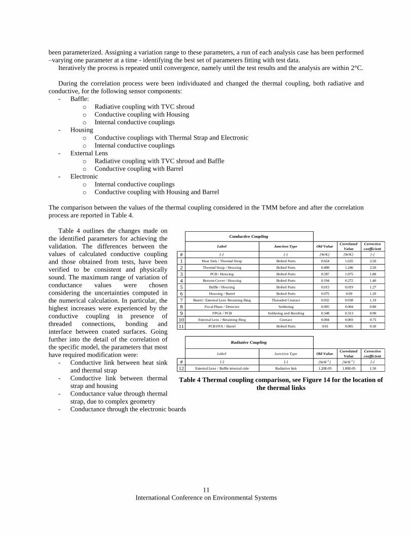
The comparison between the values of the thermal coupling considered in the TMM before and after the correlation
process are reported in Table 4.
Table 4 outlines the changes made on
the identified parameters for achieving the
validation. The differences between the
values of calculated conductive coupling
and those obtained from tests, have been
verified to be consistent and physically
sound. The maximum range of variation of
conductance values were chosen
considering the uncertainties computed in
the numerical calculation. In particular, the
highest increases were experienced by the
conductive coupling in presence of
threaded connections, bonding and
interface between coated surfaces. Going
further into the detail of the correlation of
the specific model, the parameters that most
have required modification were:
- Conductive link between heat sink
and thermal strap
- Conductive link between thermal
strap and housing
- Conductance value through thermal
strap, due to complex geometry
- Conductance through the electronic boards
Table 4 Thermal coupling comparison, see Figure 14 for the location of
the thermal links
Label Junction Type Old ValueCorrelated
Value
Cerrective
coefficient
# [-] [-] [W/K] [W/K] [-]
1 Heat Sink / Thermal Strap Bolted Parts 0.654 1.635 2.50
2 Thermal Strap / Housing Bolted Parts 0.498 1.246 2.50
3 PCB / Housing Bolted Parts 0.597 1.075 1.80
4 Bottom Cover / Housing Bolted Parts 0.194 0.272 1.40
5 Baffle / Housing Bolted Parts 0.015 0.019 1.27
6 Housing / Barrel Bolted Parts 0.075 0.09 1.20
7 Barrel / External Lens Retaining Ring Threaded Contact 0.032 0.038 1.19
8 Focal Plane / Detector Soldering 0.005 0.004 0.80
9 FPGA / PCB Soldering and Bonding 0.348 0.313 0.90
10 External Lens / Retaining Ring Contact 0.004 0.003 0.75
11 PCB FPA / Barrel Bolted Parts 0.01 0.005 0.50
Label Junction Type Old ValueCorrelated
Value
Cerrective
coefficient
# [-] [-] [W/K4] [W/K
4] [-]
12 External Lens / Baffle internal side Radiative link 1.20E-05 1.80E-05 1.50
Conductive Coupling
Radiative Coupling
International Conference on Environmental Systems
12
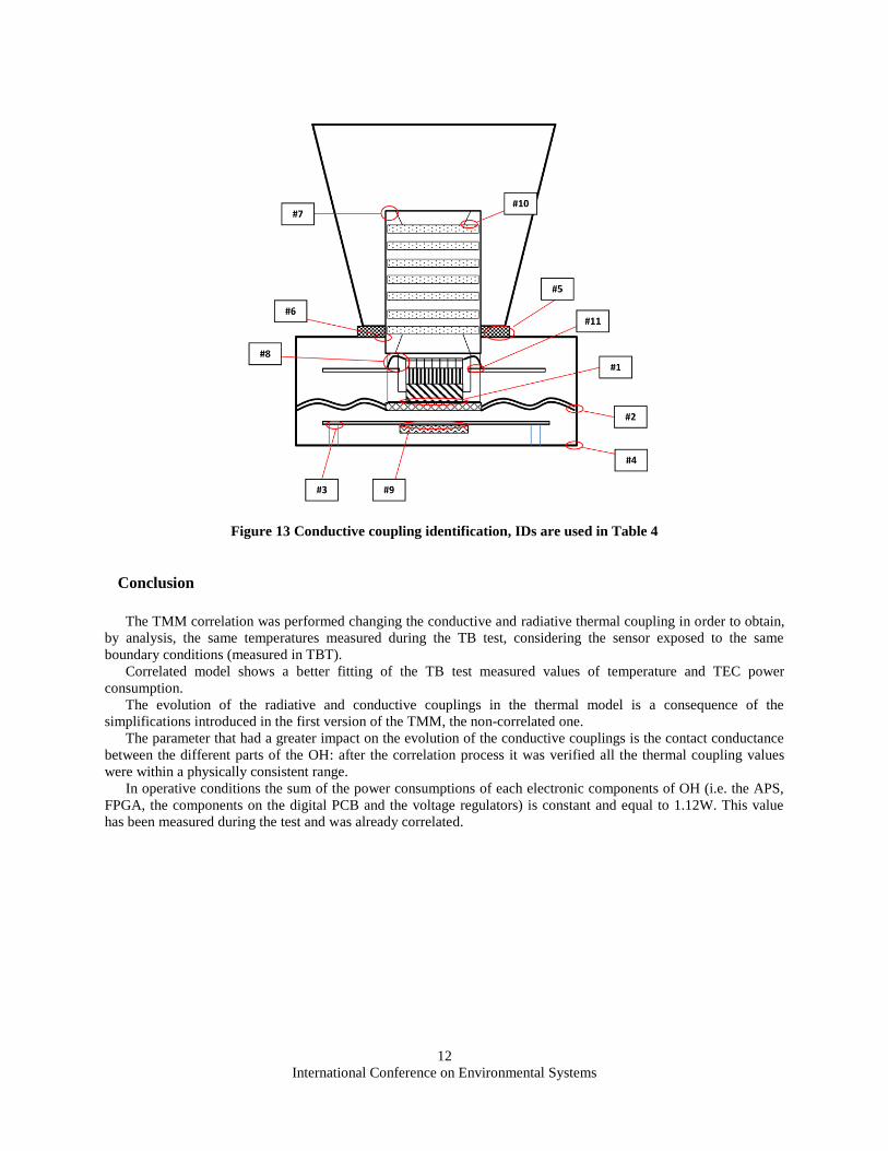
Figure 13 Conductive coupling identification, IDs are used in Table 4
Conclusion
The TMM correlation was performed changing the conductive and radiative thermal coupling in order to obtain,
by analysis, the same temperatures measured during the TB test, considering the sensor exposed to the same
boundary conditions (measured in TBT).
Correlated model shows a better fitting of the TB test measured values of temperature and TEC power
consumption.
The evolution of the radiative and conductive couplings in the thermal model is a consequence of the
simplifications introduced in the first version of the TMM, the non-correlated one.
The parameter that had a greater impact on the evolution of the conductive couplings is the contact conductance
between the different parts of the OH: after the correlation process it was verified all the thermal coupling values
were within a physically consistent range.
In operative conditions the sum of the power consumptions of each electronic components of OH (i.e. the APS,
FPGA, the components on the digital PCB and the voltage regulators) is constant and equal to 1.12W. This value
has been measured during the test and was already correlated.

International Conference on Environmental Systems
13
References
1John H. Lienhard IV, John H. Lienhard V, A Heat Transfer Textbook, 3rd ed., Phlogiston Press, Cambridge Massachusetts,
2008, Chaps. 2, 4, 5, 10. 2David G. Gilmore, Spacecraft Thermal Control Handbook – Volume I: Fundamental Technologies, 2nd ed., The Aerospace
Press, El Segundo, California, 2002, Chaps. 4, 5, 6, 8, 15, 16, 19. 3Chakravarti V. Madhusudana, Thermal Contact Conductance, 2nd ed., Springer, Sydney, NSW, 2014. 4ECSS, ECSS –E-ST-31-C - Space Engineering – Thermal Control General Requirements, ESA Requirements and Standard
Division, 2008. 5ECSS, ECSS –E-ST-10-03C - Space Engineering –Teasting , ESA Requirements and Standard Division, 2012. 6ESATAN, ESATAN-TMS Thermal Engineering Manual, ITP Engines UK Ltd., Whetstone, Leicester, UK, 2010.