irmc s4 - concepts and interfaces -...
TRANSCRIPT
User Guide - English
FUJITSU Software ServerView Suite
iRMC S4Concepts and Interfaces
Edition March 2017

Comments… Suggestions… Corrections…The User Documentation Department would like to know your opinion of this manual. Yourfeedback helps us optimize our documentation to suit your individual needs.
Feel free to send us your comments by e-mail [email protected].
Certified documentation according to DIN EN ISO 9001:2008To ensure a consistently high quality standard and user-friendliness, this documentation wascreated to meet the regulations of a quality management system which complies with therequirements of the standard DIN EN ISO 9001:2008.
cognitas. Gesellschaft für Technik-Dokumentation mbH
www.cognitas.de
Copyright and trademarksCopyright 2017 FUJITSU LIMITED.
All rights reserved.
Delivery subject to availability; right of technical modifications reserved.
All hardware and software names used are trademarks of their respective manufacturers.

Contents
1 Preface 6
1.1 Purpose and target groups 7
1.2 ServerView Suite link collection 7
1.3 Documentation for the ServerView Suite 9
1.4 Documents for the iRMC 9
1.5 What's new 9
1.6 Notational conventions 10
2 IPMI 11
2.1 Technical Background 11
2.2 IPMI over LAN 16
2.3 Supported IPMI OEM Commands 17
2.3.1 SCCI-compliant Power On/Off commands 182.3.2 SCCI-compliant communication commands 222.3.3 SCCI-compliant signaling command 242.3.4 BIOS-specific commands 252.3.5 iRMC S4-specific commands 27
2.4 Data Center Management Interface 35
2.5 Serial over LAN (SOL) 35
3 iRMC Configuration 37
3.1 Configuration via the iRMC web interface 37
3.2 Configuration via the Server Configuration Manager 38
3.2.1 Start of Server Configuration Manager via ServerView Installation Manager 393.2.2 Starting Server Configuration Manager via Windows Start menu 393.2.3 Starting Server Configuration Manager via Operations Manager 40
3.3 Configuration via Remote Manager 42
3.4 Configuration via the Remote Manager (Serial) interface 43
3.5 Configuration via text console redirection 43
3.6 Configuration via scripting 44
3.7 Configuration via UEFI setup utility 45
3.7.1 Configuring the LAN interface 463.7.2 Configuring text console redirection 473.7.3 Configuring the serial interface 49
iRMC S4 - Concepts and Interfaces 3

Content
4 Configuration via Telnet/SSH (Remote Manager) 51
4.1 Requirements on the managed server 51
4.2 Required user permissions 52
4.3 Logging in 55
4.4 Main menu 56
4.4.1 System Information menu 574.4.2 Power Management menu 584.4.3 Enclosure Information menu 594.4.3.1 System Eventlog 604.4.3.2 Internal Eventlog 61
4.4.4 Service processor menu 624.4.5 RAID Management menu 634.4.6 Console Redirection (EMS/SAC) 634.4.7 Shell menu 644.4.8 Console Logging 644.4.9 Console Logging Run State Menu 65
4.5 Command Line Protocol 66
5 Configuration via scripting 69
5.1 REST 69
5.2 Profile Management 72
5.2.1 Profiles 725.2.2 Automatic BIOS parameter backup 73
5.3 CIM 74
5.4 Configuration via SCCI API 75
5.4.1 iRMC configuration data 755.4.1.1 Benefits of remote iRMC configuration 765.4.1.2 SCCI file format 775.4.1.3 Parameters of SCCI provider-specific commands 775.4.1.4 Restrictions 795.4.1.5 Export / import of configuration data 80
5.4.2 Supported SCCI commands 805.4.3 Script Examples 815.4.3.1 cURL examples 815.4.3.2 Visual Basic (VB) script 825.4.3.3 Python script 82
5.4.4 Password encryption utility 84
6 Monitoring the iRMC 86
6.1 Monitoring with SNMP 86
iRMC S4 - Concepts and Interfaces 4
Content
6.2 iRMC system report 88
6.2.1 cURL script for download 886.2.2 Visual Basic script 896.2.3 Information sections 906.2.3.1 Summary section 916.2.3.2 BIOS section 926.2.3.3 Processor section 926.2.3.4 Memory section 936.2.3.5 Fans section 946.2.3.6 Temperature section 946.2.3.7 Power supplies section 956.2.3.8 Voltages section 956.2.3.9 IDPROMS section 956.2.3.10 SensorDataRecords section 956.2.3.11 PCIDevices section 966.2.3.12 SystemEventLog section 966.2.3.13 InternalEventLog section 976.2.3.14 BootStatus section 976.2.3.15 ManagementControllers section 976.2.3.16 Settings section 986.2.3.17 Adapters section 986.2.3.18 Interfaces section 986.2.3.19 Ports section 996.2.3.20 SNMPAgents section 996.2.3.21 ServerViewRaid section 100
iRMC S4 - Concepts and Interfaces 5

1 PrefaceModern server systems are becoming increasingly complex. The requirements with respectto the management of such systems are growing accordingly.
In response to this development, a number of vendors founded the “Intelligent PlatformManagement Interface” (IPMI) initiative with the objective of defining a standardized,abstract, message-based interface between the central system controller (BaseboardManagement Controller - BMC) and intelligent hardware for platform management. Forfurther details on IPMI, "Technical Background" on page 11.
The integrated Remote Management Controller iRMC represents a BMC with integrated LANconnection and extended functions. In this way, the iRMC offers comprehensive controlover PRIMERGY servers, irrespective of the system status. In particular, the iRMC allows forout-of-band management (Lights Out Management, LOM) of PRIMERGY servers. Out-of-band management uses of a dedicated management channel that enables a systemadministrator to monitor and manage servers via remote control regardless of whetherthe server is powered on.
Figure 1: iRMC S4 on the system board of a PRIMERGY server
As an autonomous system on the system board of a modern PRIMERGY server, the iRMChas its own operating system, its own web server, separate user management andindependent alert management. The iRMC remains powered up even when the server is instand-by mode.
Beyond making it possible to manage a PRIMERGY server out-of-band, the enhancedfunctions of the newest version of the iRMC, which comes with an integrated SD card,allows for comprehensive life cycle management of a PRIMERGY server. As life cyclemanagement is largely integrated ("embedded") in and entirely controlled by the iRMC, itis called "embedded Life Cycle Management (eLCM)".
iRMC S4 - Concepts and Interfaces 6

1.1 Purpose and target groups
Some eLCM functions require the iRMC to communicate and cooperate with the ServerViewAgentless Service running on the managed server. Communicating with the ServerViewAgentless Service also provides the iRMC with additional in-band information.
1.1 Purpose and target groupsThis manual is aimed at system administrators, network administrators, and service staffwho have a sound knowledge of hardware and software. It provides basic information onthe concepts of the iRMC and deals with the following aspects in detail:
l The IPMI chapter comprises the basic principles of the IPMI protocol and the supportedOEM commands, that can be used within a script.
l iRMC Configuration gives an overview of the various possibilities to configure theiRMC.
l The next chapters describe the configuration of the iRMC in detail using differentinterfaces:o Remote Managero Several APIs
l Monitoring the iRMC comprises the methods of how to monitor the iRMC.
1.2 ServerView Suite link collectionVia the ServerView Suite link collection, Fujitsu provides you with numerous downloadsand further information on the ServerView Suite and PRIMERGY servers.
Under ServerView Suite, links are offered on the following topics:
l Forum
l Service Desk
l Manuals
l Product information
l Security information
l Software downloads
l Training
iRMC S4 - Concepts and Interfaces 7

1.2 ServerView Suite link collection
Software downloads includes the following downloads:
o Current software statuses for the ServerView Suite as well as additional Readmefiles.
o Information files and update sets for system software components (BIOS,firmware, drivers, ServerView Agents and ServerView Update Agent) forupdating the PRIMERGY servers via ServerView Update Manager or for locallyupdating individual servers via ServerView Update Manager Express.
o The current versions of all documentation on the ServerView Suite.
You can retrieve the downloads free of charge.
Under PRIMERGY Server, links are offered on the following topics:
l Service Desk
l Manuals
l Product information
l Spare parts catalogue
Access to the ServerView Suite link collection
You can reach the link collection of the ServerView Suite in various ways:
1. Via ServerView Operations Manager.
l Select Help – Links on the start page or the menu bar.
2. Via the start page of the online documentation for the ServerView Suite on the Fujitsumanual server.
You access the start page of the online documentation via the followinglink:
http://manuals.ts.fujitsu.com
l In the selection list on the left, select x86 Servers.
l On the right, click PRIMERGY ServerView Links under Selected documents.
3. Via the ServerView Suite DVD 2.
l In the start window of the ServerView Suite DVD 2, select the option ServerViewSoftware Products.
l On the menu bar select Links.
This opens the start page of the ServerView Suite link collection.
iRMC S4 - Concepts and Interfaces 8
1.3 Documentation for the ServerView Suite
1.3 Documentation for the ServerView SuiteThe documentation can be downloaded free of charge from the Internet. You will find theonline documentation at http://manuals.ts.fujitsu.com under the link x86 Servers.
ServerView Sitemap
For an overview of the documentation to be found under ServerView Suite as well as thefiling structure, see the ServerView Suite Sitemap:
1. In the selection list on the left, select x86 Servers and then Software.
2. On the right, select ServerView Suite.
3. Click ServerView Suite Sitemap under Selected documents.
1.4 Documents for the iRMCThis manual is part of a documentation suite describing the iRMC S4 up to firmwareversion 8.8. The documentation suite of the iRMC S4 comprises the following manuals:
l iRMC S4 Web Interface
l iRMC S4 Configuration and Maintenance
l iRMC S4 Concepts and Interfaces
1.5 What's newThe following changes are made in this edition:
l Minor changes regarding SystemReport and Agent Connect Status
l Update IPMI command description
iRMC S4 - Concepts and Interfaces 9

1.6 Notational conventions
1.6 Notational conventionsThe following notational conventions are used in this manual:
Notationalconventions
Indicates
Indicates various types of risks, namely health risks, risk of data lossand risk of damage to devices.
Indicates additional relevant information and tips.
Bold Indicates references to names of interface elements.
monospace Indicates system output and system elements, for example file namesand paths.
monospacesemibold
Indicates statements that are to be entered using the keyboard.
blue continuoustext
Indicates a link to a related topic.
purplecontinuous text
Indicates a link to a location you have already visited.
<abc> Indicates variables which must be replaced with real values.
[abc] Indicates options that can be specified (syntax).
[Key] Indicates a key on your keyboard. If you need to explicitly enter text inuppercase, the Shift key is specified, for example [Shift] + [A] for A. Ifyou need to press two keys at the same time, this is indicated by a plussign between the two key symbols.
Screenshots
The screenshots are to some degree system-dependent and consequently will notnecessarily match the output on your system in all the details. The menus and theircommands can also contain system-dependent differences.
iRMC S4 - Concepts and Interfaces 10
2 IPMI
2.1 Technical BackgroundThe iRMC makes the BMC functions available over the IPMI interface.
Intelligent Platform ManagementThe “Intelligent Platform Management” initiative is a response to the increasingcomplexity of modern server systems. A number of manufacturers have joined thisinitiative in order to come up with a new solution for monitoring these server systems.
The term “Intelligent Platform Management” expresses the core aspect of this approach tothe solution: Functions for monitoring and recovery of systems are implemented directly inthe hardware and firmware for platform management.
ObjectiveThe objective was to define a standardized, abstract and message-based interface betweenthe central system controller (Baseboard Management Controller - BMC) and intelligentplatform management hardware.
The standardization committees combined the central characteristics of various platformmanagement modules into standardized descriptions.
DefinitionThe IPMI specification defines:
“IPMI is a hardware level interface specification that is ‘management software neutral’providing monitoring and control functions that can be exposed through standardmanagement software interfaces such as DMI, WMI, CIM, SNMP, etc. As a hardware levelinterface, it sits at the bottom of a typical management software stack”.
AdvantageThe IPMI specifications ensure the independence of functions for inventory, logging,recovery and monitoring of a system by the system processor, BIOS or operating system.
This means that a system can still be involved in platform management when it is shutdown and turned off.
IPMI and other management standardsIPMI is best used in conjunction with system management software running under therelevant operating system. Integration of the IPMI functionality into the managementfunctionality offered by a management application and the operating system results in apowerful platform management environment.
iRMC S4 - Concepts and Interfaces 11
2.1 Technical Background
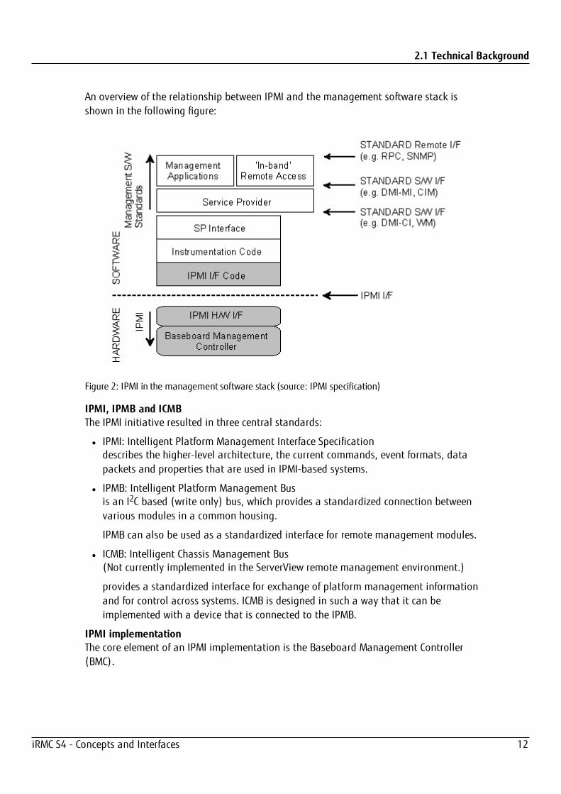
An overview of the relationship between IPMI and the management software stack isshown in the following figure:
Figure 2: IPMI in the management software stack (source: IPMI specification)
IPMI, IPMB and ICMBThe IPMI initiative resulted in three central standards:
l IPMI: Intelligent Platform Management Interface Specificationdescribes the higher-level architecture, the current commands, event formats, datapackets and properties that are used in IPMI-based systems.
l IPMB: Intelligent Platform Management Busis an I2C based (write only) bus, which provides a standardized connection betweenvarious modules in a common housing.
IPMB can also be used as a standardized interface for remote management modules.
l ICMB: Intelligent Chassis Management Bus(Not currently implemented in the ServerView remote management environment.)
provides a standardized interface for exchange of platform management informationand for control across systems. ICMB is designed in such a way that it can beimplemented with a device that is connected to the IPMB.
IPMI implementationThe core element of an IPMI implementation is the Baseboard Management Controller(BMC).
iRMC S4 - Concepts and Interfaces 12

2.1 Technical Background
The BMC performs the following tasks:
l The BMC organizes the interface between the system management software and theplatform management hardware.
l It provides autonomous functions for monitoring, event logging and recovery control.
l The BMC acts as a gateway between the system management software and IPMB.
IPMI allows platform management to be extended: Additional management controllerscan be connected via the IPMB. The IPMB is an I2C based serial bus, which runs betweenthe main modules of the system. It is used for communication with and between themanagement controllers.
With the support of multiple management controllers, IPMI provides a scalablearchitecture: A complex server system can use multiple controllers for monitoring differentsubsystems, e.g. power supplies, hot swap RAID drive modules etc.
In addition, IPMI provides ‘low level’ I2C commands, which can be accessed via amanagement controller connected to the IPMB on 'unintelligent' I2C modules that cannotprocess IPMI commands.
An overview of the fundamental elements of an IPMI implementation is shown in thefollowing figure:
iRMC S4 - Concepts and Interfaces 13

2.1 Technical Background
Figure 3: IPMI block diagram (source: IPMI specification)
IPMI and “in-band” and “out-of-band” managementIn the field of system management, a distinction is made between “in-band” and “out-of-band” management:
l The term “in-band” management is used when the operating system is running on themanaged server.
l The term “out-of-band” management is used when the operating system is not runningon the managed server, for instance if the hardware is faulty.
iRMC S4 - Concepts and Interfaces 14

2.1 Technical Background
As different interfaces are available in an environment with IPMI compatible systems, youcan manage IPMI compatible systems either “in-band” or “out-of-band”.
Channel concept under IPMI‘Channels’ provide the mechanisms with which IPMI messages are routed to the BMC viavarious connection carriers. Up to nine channels can be supported. The system interfaceand the primary IPMB are fixed. The other seven channels are available for theimplementation.
Channels can be either ‘session based’ or ‘sessionless’. The ‘session’ concept has twomeanings: It is either a concept for user authentication or a concept for routing multipleIPMI message streams via a single channel.
Examples of ‘session based’ channels are LAN channels or serial/modem channels.Examples of ‘sessionless’ channels are the system interface and the IPMB.
User identificationsFor ‘session based’ channels, a user login is necessary. By contrast, the ‘sessionless’channels have no user authentication.
Under IPMI, the user configuration is channel specific. Thus, users can have differentprivileges depending on whether they are accessing the BMC via the LAN channel or theserial channel.
FencingIn high available clusters problems can arise if the node considered failed is not actuallyfailed. If, for any reason, it is not really down and it is still connected to the storagesolution, the VM process can alter the virtual machine drives.
With two VM instances running, the drives can be easily corrupted, leaving the virtualmachine in an inconsistent state. This is where fencing comes in. With fencing, even whenthe cluster doesn’t know what is happening on some node, you can make sure that nodedoesn’t run any or certain important resources.
So fencing refers to the idea of isolating nodes considered down and preventing them fromwriting anything to the shared storage. The fencing feature on the iRMC can request a shutdown of a remote device, if IPMI fencing is enabled. See the "iRMC S4 - Web Interface"manual for how to enable IPMI fencing.
ReferencesInformation about the IPMI standards can be found on the Internet:
http://developer.intel.com/design/servers/ipmi/index.htm
iRMC S4 - Concepts and Interfaces 15

2.2 IPMI over LAN
2.2 IPMI over LANIPMI-over-LAN is the current name for the specification of the LAN interface in the IPMIstandard. This specification stipulates how IPMI messages can be sent to or from the BMCof a managed system - encapsulated in RMCP (Remote Management Control Protocol)data packets. These RMCP data packets are transferred via an Ethernet LAN connectionusing the UDP (User Datagram Protocol) under IPv4 (Internet Protocol Version 4).
The RMCP protocol has been specified to support the management of system statuses inwhich the operating system is not running. The RMCP is a simple inquiry/responseprotocol.
The interface for such a connection is provided on an onboard LAN controller assigned tothe BMC.
The interface can only be provided by an on-board LAN controller, not by aninserted LAN card.
Of the two ports that RCMP uses under UDP, the BMC communicates with the LANcontroller via port 623 (primary RMCP Port).
Figure 4: BMC and LAN controller
iRMC S4 - Concepts and Interfaces 16

2.3 Supported IPMI OEM Commands
2.3 Supported IPMI OEM CommandsThe following OEM-specific IPMI commands are supported by the iRMC S4:
SCCI-compliant Power On/Off commands(SCCI: ServerView Common Command Interface)
0115 Get Power On Source
0116 Get Power Off Source
011C Set Power Off Inhibit
011D Get Power Off Inhibit
0120 Set Next Power On Time
SCCI-compliant communication commands
0205 System OS Shutdown Request
0206 System OS Shutdown Request and Reset
0208 Agent Connect Status
0209 Shutdown Request Canceled
SCCI-compliant signaling commands
1002 Write to System Display
BIOS-specific command
F109 Get BIOS POST State
F115 Get CPU Info
iRMC S4-specific commands
F510 Get System Status
F512 Get EEPROM Version Info
F542 Get HDD lightpath status (Component Status Signal Read)
F543 Get SEL entry long text
F545 Get SEL entry text
F5B0 Set Identify LED
F5B1 Get Identify LED
F5B3 Get Error LED
F5E0 Set Configuration Space to Default Values
F5F8 Delete User ID
iRMC S4 - Concepts and Interfaces 17

2.3 Supported IPMI OEM Commands
The following sections describe the individual OEM-specific IPMI commands.
Description format
The OEM-specific IPMI commands contained in this chapter are described in the formatused by the IPMI standard for describing IPMI commands.
The IPMI standard describes the IPMI commands using command tables which list theinput and output parameters for each command.
You can find information on the IPMI standards on the Internet under:http://developer.intel.com/design/servers/ipmi/index.htm
2.3.1 SCCI-compliant Power On/Off commands
01 15 - Get Power On Source
This command returns the reason for the most recent Power On. The possible reasons arelisted below.
Request Data - B8 NetFnlLUN: OEM/Group
- 01 Cmd : Command Group Communication
1:3 80 28 00 IANA-Enterprise-Number FTS, LS byte first
4 15 Command specifier
Response Data - BC
- 01
1 Completion code
2:4 80 28 00 IANA-Enterprise-Number FTS, LS byte first
3 01 Data Length
4 Power on Source: Cause of last power on
Power onSource
Description
0x00 Software or command
0x01 Power switch (on the front panel or keyboard)
0x02 Automatic restart after an AC power failure
0x03 Clock or timer (hardware RTC or software timer)
0x04 Automatic restart after fan failure shutdown
0x05 Automatic restart after critical temperature shutdown
iRMC S4 - Concepts and Interfaces 18
2.3 Supported IPMI OEM Commands
Power onSource
Description
0x08 Reboot after watchdog timeout
0x09 Remote on (modem RI line, SCSI termination power, LAN, chip card reader...)
0x0C Reboot after a CPU error
0x15 Reboot by hardware reset
0x16 Reboot after warm start
0x1A Powered on by a PCI Bus Power Management Event
0x1D Powered on by remote control via remote manager
0x1E Reboot/reset by remote control via remote manager
0x24 Automatic Power on/off for VIOM Inventory Boot
0x25 Automatic Power on/off for VIOM Init Boot
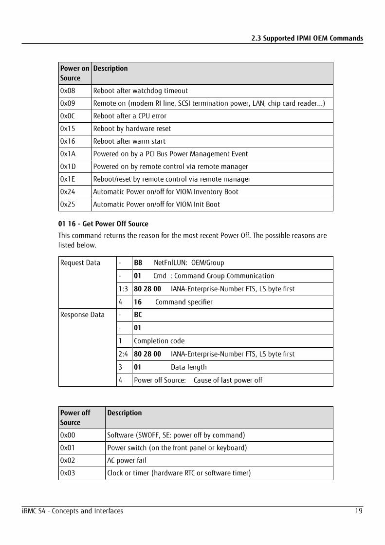
01 16 - Get Power Off Source
This command returns the reason for the most recent Power Off. The possible reasons arelisted below.
Request Data - B8 NetFnlLUN: OEM/Group
- 01 Cmd : Command Group Communication
1:3 80 28 00 IANA-Enterprise-Number FTS, LS byte first
4 16 Command specifier
Response Data - BC
- 01
1 Completion code
2:4 80 28 00 IANA-Enterprise-Number FTS, LS byte first
3 01 Data length
4 Power off Source: Cause of last power off
Power offSource
Description
0x00 Software (SWOFF, SE: power off by command)
0x01 Power switch (on the front panel or keyboard)
0x02 AC power fail
0x03 Clock or timer (hardware RTC or software timer)
iRMC S4 - Concepts and Interfaces 19

2.3 Supported IPMI OEM Commands
Power offSource
Description
0x04 Fan failure
0x05 Critical temperature
0x08 Final power-off after repeated watchdog timeouts
0x0C Final power-off after repeated CPU errors
0x1D Powered off by remote control via remote manager
0x24 Automatic Power on/off for VIOM Inventory Boot
0x25 Automatic Power on/off for VIOM Init Boot
01 1C - Set Power Off Inhibit
This command sets the Power Off Inhibit flag, which temporarily suppresses anyunfounded attempt to power down the server.
If the Power Off Inhibit flag is set, the firmware saves the cause of any attempt toperform a Power Off, Power Cycle or restart of the server, but does not perform the action.The cause of the most recent attempt to perform a Power Off, Power Cycle or restart of theserver is always saved at any given time. The stored action is only performed when thePower Off Inhibit flag is reset.
The Power Off Inhibit flag is automatically reset after a power failure or when thereset button is pressed.
The effect of the Power Off Inhibit flag is the same as that of the Dump flag usedwhen creating a main memory dump. In this case, the initiator must set the flag beforemaking the dump and reset it when the dump is complete.
Request Data - B8 NetFn|LUN: OEM/Group
- 01 Cmd : Command Group Communication
1:3 80 28 00 IANA-Enterprise-Number FTS, LS Byte first
4 1C Command specifier
5 00 Object ID
6:7 00 00 Value ID
8 01 Data length
9 Power Off Inhibit Flag: 0 no Inhibit, 1 Inhibit
Response Data - BC
- 01
1 Completion code
2:4 80 28 00 IANA-Enterprise-Number FTS, LS Byte first
iRMC S4 - Concepts and Interfaces 20
2.3 Supported IPMI OEM Commands
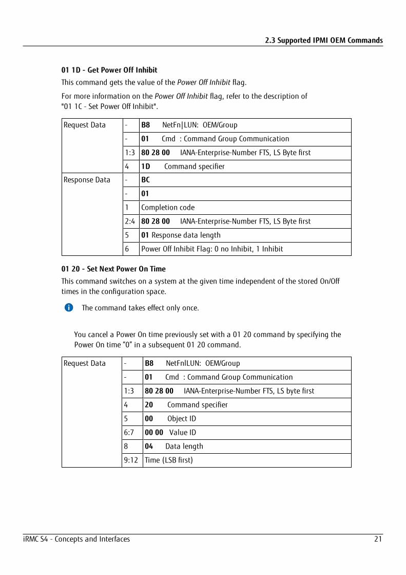
01 1D - Get Power Off Inhibit
This command gets the value of the Power Off Inhibit flag.
For more information on the Power Off Inhibit flag, refer to the description of"01 1C - Set Power Off Inhibit".
Request Data - B8 NetFn|LUN: OEM/Group
- 01 Cmd : Command Group Communication
1:3 80 28 00 IANA-Enterprise-Number FTS, LS Byte first
4 1D Command specifier
Response Data - BC
- 01
1 Completion code
2:4 80 28 00 IANA-Enterprise-Number FTS, LS Byte first
5 01 Response data length
6 Power Off Inhibit Flag: 0 no Inhibit, 1 Inhibit
01 20 - Set Next Power On Time
This command switches on a system at the given time independent of the stored On/Offtimes in the configuration space.
The command takes effect only once.
You cancel a Power On time previously set with a 01 20 command by specifying thePower On time “0” in a subsequent 01 20 command.
Request Data - B8 NetFnlLUN: OEM/Group
- 01 Cmd : Command Group Communication
1:3 80 28 00 IANA-Enterprise-Number FTS, LS byte first
4 20 Command specifier
5 00 Object ID
6:7 00 00 Value ID
8 04 Data length
9:12 Time (LSB first)
iRMC S4 - Concepts and Interfaces 21

2.3 Supported IPMI OEM Commands
Response Data - BC
- 01
1 Completion code
2:4 80 28 00 IANA-Enterprise-Number FTS, LS byte first
Time (LSB first)
Time (UNIX-specific format) when the system switches on again. Time is NOT stored innon-volatile memory. Resolution is 1 minute. After the system has switched on, Time isset to 0 internally.If Time == 0, the system is not switched on.
2.3.2 SCCI-compliant communication commands
The SCCI-compliant communication commands require that the Agent Service isrunning under the OS. To execute the commands, the iRMC S4 communicates withthe agent that finally performs the action.
02 05 - System OS Shutdown Request
This command initiates shutdown of the server’s operating system.
Request Data - B8 NetFnlLUN: OEM/Group
- 02 Cmd : Command Group Communication
1:3 80 28 00 IANA-Enterprise-Number FTS, LS byte first
4 05 Command Specifier
Response Data - BC
- 02
1 Completion Code
2:4 80 28 00 IANA-Enterprise-Number FTS, LS byte first
02 06 - System OS Shutdown Request and Reset
This command initiates the shutdown of the server’s operating system and subsequentlyrestarts the system.
Request Data - B8 NetFnlLUN: OEM/Group
- 02 Cmd : Command Group Communication
1:3 80 28 00 IANA-Enterprise-Number FTS, LS byte first
4 06 Command Specifier
iRMC S4 - Concepts and Interfaces 22

2.3 Supported IPMI OEM Commands
Response Data - BC
- 02
1 Completion Code
2:4 80 28 00 IANA-Enterprise-Number FTS, LS byte first
02 08 - Agent Connect Status
This command checks whether the agent is active.
RequestData
- B8 NetFnlLUN: OEM/Group
- 02 Cmd : Command Group Communication
1:3 80 28 00 IANA-Enterprise-Number FTS, LS byte first
4 08 Command Specifier
ResponseData
- BC
- 02
1 Completion Code
2:4 80 28 00 IANA-Enterprise-Number FTS, LS byte first
5 01 Data Length (01h or 03h)
6 Connect Status: 00 = Connection lost, agent not connected. 01 = Connection re-established, agent connected. 003 = agent connection is established and agent connection supportedfeatures in bytes 7 and 8
04 = agentless service is established and agentless service supportedfeatures in bytes 7 and 8
7:8 (optional)Agent / Agentless service supported features
Bit field with value 1 if supported and value 0 if not supported[0]: HTI support
[1]: Graceful shutdown / Reboot support
[2]: iRMC restart support (FW update) …[15]: Reserved
02 09 - Shutdown Request Canceled
This command cancels a shutdown request that has been issued.
iRMC S4 - Concepts and Interfaces 23
2.3 Supported IPMI OEM Commands
Request Data - B8 NetFnlLUN: OEM/Group
- 02 Cmd : Command Group Communication
1:3 80 28 00 IANA-Enterprise-Number FTS, LS byte first
4 09 Command Specifier
Response Data - BC
- 02
1 Completion Code
2:4 80 28 00 IANA-Enterprise-Number FTS, LS byte first
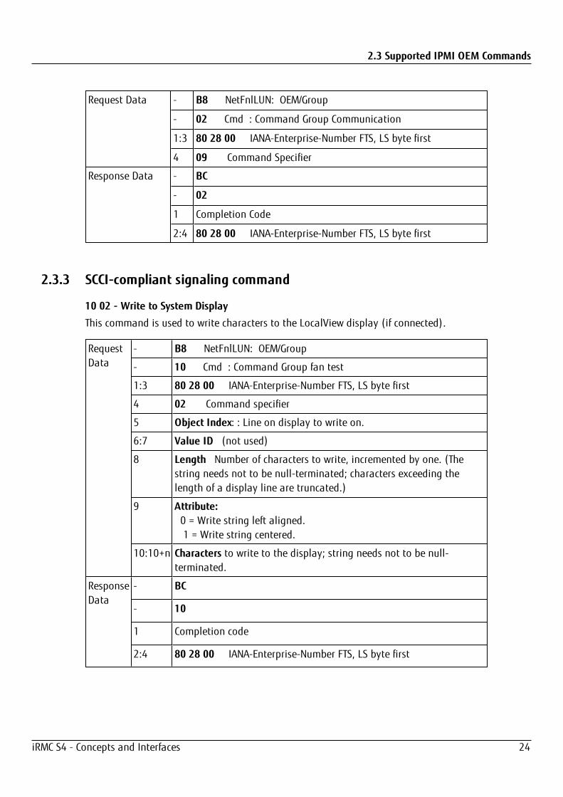
2.3.3 SCCI-compliant signaling command
10 02 - Write to System Display
This command is used to write characters to the LocalView display (if connected).
RequestData
- B8 NetFnlLUN: OEM/Group
- 10 Cmd : Command Group fan test
1:3 80 28 00 IANA-Enterprise-Number FTS, LS byte first
4 02 Command specifier
5 Object Index: : Line on display to write on.
6:7 Value ID (not used)
8 Length Number of characters to write, incremented by one. (Thestring needs not to be null-terminated; characters exceeding thelength of a display line are truncated.)
9 Attribute: 0 = Write string left aligned. 1 = Write string centered.
10:10+n Characters to write to the display; string needs not to be null-terminated.
ResponseData
- BC
- 10
1 Completion code
2:4 80 28 00 IANA-Enterprise-Number FTS, LS byte first
iRMC S4 - Concepts and Interfaces 24

2.3 Supported IPMI OEM Commands
2.3.4 BIOS-specific commands
F1 09 - Get BIOS POST State
This command provides information whether BIOS is in POST.
Request Data - B8 NetFnlLUN: OEM/Group
- F1 Cmd : Command Group BIOS
1:3 80 28 00 IANA-Enterprise-Number FTS, LS Byte first
4 09 Command Specifier
Response Data - BC
- F1
1 Completion Code
2:4 80 28 00 IANA-Enterprise-Number FTS, LS Byte first
5 [7:3] - reserved[0] - BIOS POST State : 0 = BIOS is not in POST 1 = BIOS is in POST
[1] - BIOS Video State:
0 = Video initialization is not yet done
1 = Video initialization is done
[2] - Uncorrectable Error Indicators State:
0 = Indicators are not yet cleared
1 = Indicators are cleared
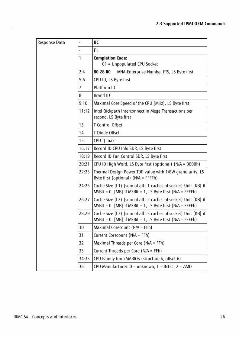
F1 15 - Get CPU Info
This command returns CPU-internal information. The iRMC gets this information from theBIOS during the POST phase.
Request Data - B8 NetFnlLUN: OEM/Group
- F1 Cmd : Command Group BIOS
1:3 80 28 00 IANA-Enterprise-Number FTS, LS Byte first
4 15 Command Specifier
5 Socket Number (0-based) of the CPU
iRMC S4 - Concepts and Interfaces 25
2.3 Supported IPMI OEM Commands
Response Data - BC
- F1
1 Completion Code: 01 = Unpopulated CPU Socket
2:4 80 28 00 IANA-Enterprise-Number FTS, LS Byte first
5:6 CPU ID, LS Byte first
7 Platform ID
8 Brand ID
9:10 Maximal Core Speed of the CPU [MHz], LS Byte first
11:12 Intel Qickpath Interconnect in Mega Transactions persecond, LS Byte first
13 T-Control Offset
14 T-Diode Offset
15 CPU TJ max
16:17 Record ID CPU Info SDR, LS Byte first
18:19 Record ID Fan Control SDR, LS Byte first
20:21 CPU ID High Word, LS Byte first (optional) (N/A = 0000h)
22:23 Thermal Design Power TDP value with 1/8W granularity, LSByte first (optional) (N/A = FFFFh)
24:25 Cache Size (L1) (sum of all L1 caches of socket) Unit [KB] ifMSBit = 0, [MB] if MSBit = 1, LS Byte first (N/A = FFFFh)
26:27 Cache Size (L2) (sum of all L2 caches of socket) Unit [KB] ifMSBit = 0, [MB] if MSBit = 1, LS Byte first (N/A = FFFFh)
28:29 Cache Size (L3) (sum of all L3 caches of socket) Unit [KB] ifMSBit = 0, [MB] if MSBit = 1, LS Byte first (N/A = FFFFh)
30 Maximal Corecount (N/A = FFh)
31 Current Corecount (N/A = FFh)
32 Maximal Threads per Core (N/A = FFh)
33 Current Threads per Core (N/A = FFh)
34:35 CPU Family from SMBIOS (structure 4, offset 6)
36 CPU Manufacturer: 0 = unknown, 1 = INTEL, 2 = AMD
iRMC S4 - Concepts and Interfaces 26
2.3 Supported IPMI OEM Commands
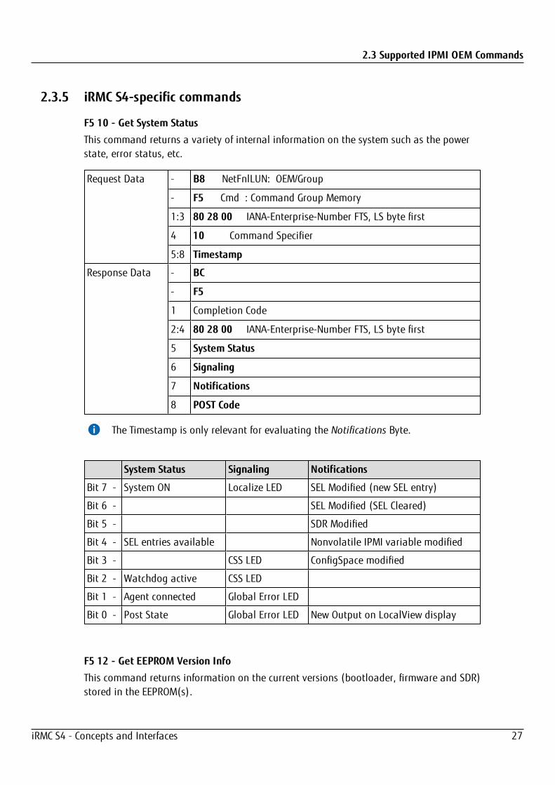
2.3.5 iRMC S4-specific commands
F5 10 - Get System Status
This command returns a variety of internal information on the system such as the powerstate, error status, etc.
Request Data - B8 NetFnlLUN: OEM/Group
- F5 Cmd : Command Group Memory
1:3 80 28 00 IANA-Enterprise-Number FTS, LS byte first
4 10 Command Specifier
5:8 Timestamp
Response Data - BC
- F5
1 Completion Code
2:4 80 28 00 IANA-Enterprise-Number FTS, LS byte first
5 System Status
6 Signaling
7 Notifications
8 POST Code
The Timestamp is only relevant for evaluating the Notifications Byte.
System Status Signaling Notifications
Bit 7 - System ON Localize LED SEL Modified (new SEL entry)
Bit 6 - SEL Modified (SEL Cleared)
Bit 5 - SDR Modified
Bit 4 - SEL entries available Nonvolatile IPMI variable modified
Bit 3 - CSS LED ConfigSpace modified
Bit 2 - Watchdog active CSS LED
Bit 1 - Agent connected Global Error LED
Bit 0 - Post State Global Error LED New Output on LocalView display
F5 12 - Get EEPROM Version Info
This command returns information on the current versions (bootloader, firmware and SDR)stored in the EEPROM(s).
iRMC S4 - Concepts and Interfaces 27

2.3 Supported IPMI OEM Commands
Request Data - B8 NetFnlLUN: OEM/Group
- F5 Cmd : Command Group Memory
1:3 80 28 00 IANA-Enterprise-Number FTS, LS byte first
4 12 Command Specifier
5 EEPROM# 00=EEPROM 1; 01=EEPROM 2
Response Data - BC
- F5
1 Completion code
2:4 80 28 00 IANA-Enterprise-Number FTS, LS byte first
5 Status 00=Checksum error runtime FW, 01=OK
6 Major FW Revision Binary coded
7 Minor FW Revision BCD coded
8:10 Aux. FW Revision Binary coded (major/minor/res.)
11 Major FW Revision ASCII coded letter
12 Major SDRR Revision BCD coded
13 Minor SDRR Revision BCD coded
14 SDRR Revision Char. ASCII coded letter
15 SDRR-ID LSB binary coded
16 SDRR-ID MSB binary coded
17 Major Booter Revision Binary coded
18 Major Booter Revision BCD coded
19:20 Aux. Booter Revision Binary coded (major/minor)
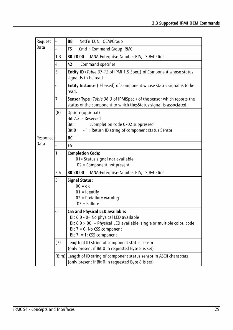
F5 42 - Get HDD lightpath status (Component Status Signal Read)
Light path diagnostics is a system of LEDs on the control panel and on the system board.When an error occurs, LEDs are lit. If the control panel indicates an error, use thedescriptions of the LEDs to diagnose the problem and take corrective action.
This command returns information on the state of a hard disk drive (HDD) slot.
iRMC S4 - Concepts and Interfaces 28
2.3 Supported IPMI OEM Commands
RequestData
- B8 NetFn|LUN: OEM/Group
- F5 Cmd : Command Group iRMC
1:3 80 28 00 IANA-Enterprise-Number FTS, LS Byte first
4 42 Command specifier
5 Entity ID (Table 37-12 of IPMI 1.5 Spec.) of Component whose statussignal is to be read.
6 Entity Instance (0-based) ofcComponent whose status signal is to beread.
7 Sensor Type (Table 36-3 of IPMISpec.) of the sensor which reports thestatus of the component to which thesStatus signal is associated.
(8) Option (optional)Bit 7:2 - ReservedBit 1 :Completion code 0x02 suppressedBit 0 - 1 : Return ID string of component status Sensor
ResponseData
- BC
- F5
1 Completion Code: 01= Status signal not available 02 = Component not present
2:4 80 28 00 IANA-Enterprise-Number FTS, LS Byte first
5 Signal Status: 00 = ok
01 = Identify 02 = Prefailure warning
03 = Failure
6 CSS and Physical LED available: Bit 6:0 - 0= No physical LED available Bit 6:0 > 00 = Physical LED available, single or multiple color, code Bit 7 = 0: No CSS component Bit 7 = 1: CSS component
(7) Length of ID string of component status sensor(only present if Bit 0 in requested Byte 8 is set)
(8:m) Length of ID string of component status sensor in ASCII characters(only present if Bit 0 in requested Byte 8 is set)
iRMC S4 - Concepts and Interfaces 29

2.3 Supported IPMI OEM Commands
F5 43 - Get SEL entry long text
This command translates a given SEL entry into long text.
RequestData
- B8 NetFn|LUN: OEM/Group
- F5 Cmd : Command group iRMC
1:3 80 28 00 IANA-Enterprise-Number FTS, LS Byte first
4 43 Command specifier
5:6 Record ID of SEL record, LS Byte first 0x0000: getfirst record 0xFFFF: get last record
7 Offset in response SEL text
8 MaxResponseDataSize size of converted SEL data(16:n) in response
(on Pilot-1 designs the max data size is 56 bytes)
ResponseData
- BC
- F5
1 Completion Code:
2:4 80 28 00 IANA-Enterprise-Number FTS, LS Byte first
5:6 Next Record ID
7:8 Actual Record ID
9 Record type
10:13 Timestamp
14 Severity: Bit 7: 0 = No CSS component 1 = CSS component Bit 6-4: 000 = INFORMATIONAL 001 = MINOR 010 = MAJOR 011 = CRITICAL 1xx = Unknown’ Bit 3-0: reserved, read as 0000
15 Data length of the whole text
16:n Converted SEL data requested part(n = 16 + MaxResponseDataSize - 1)
n + 1 String Terminator trailing '\0' character
iRMC S4 - Concepts and Interfaces 30

2.3 Supported IPMI OEM Commands
F5 45 - Get SEL Entry Short Text
This command translates a given System Event Log SEL entry into ASCII text.
Request Data - B8 NetFnlLUN: OEM/Group
- F5 Cmd : Command Group iRMC
1:3 80 28 00 IANA-Enterprise-Number FTS, LS Byte first
4 45 Command specifier
5:6 Record ID of SDR, LS Byte first
Response Data - BC
- F5
1 Completion code
2:4 80 28 00 IANA-Enterprise-Number FTS, LS Byte first
5:6 Next Record ID
7:8 Actual Record ID
9 Record type
10:13 Timestamp
14 Severity: Bit 7: 0 = No CSS component 1 = CSS component Bit 6-4: 000 = INFORMATIONAL 001 = MINOR 010 = MAJOR 011 = CRITICAL 1xx = Unknown’ Bit 3-0: reserved, read as 0000
15 Data length without trailing null terminator
16:35 Converted SEL data as ASCII, 20 bytes maximum
n+1 Trailing Null
iRMC S4 - Concepts and Interfaces 31
2.3 Supported IPMI OEM Commands
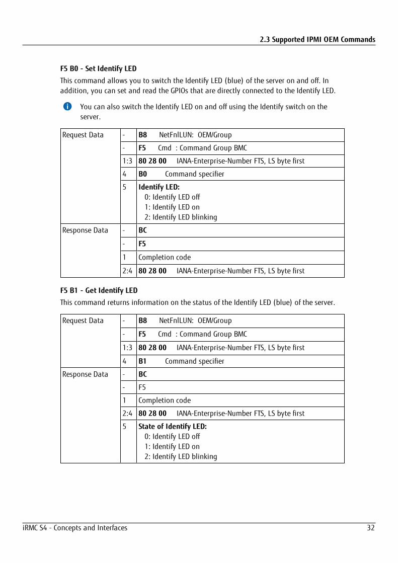
F5 B0 - Set Identify LED
This command allows you to switch the Identify LED (blue) of the server on and off. Inaddition, you can set and read the GPIOs that are directly connected to the Identify LED.
You can also switch the Identify LED on and off using the Identify switch on theserver.
Request Data - B8 NetFnlLUN: OEM/Group
- F5 Cmd : Command Group BMC
1:3 80 28 00 IANA-Enterprise-Number FTS, LS byte first
4 B0 Command specifier
5 Identify LED: 0: Identify LED off 1: Identify LED on 2: Identify LED blinking
Response Data - BC
- F5
1 Completion code
2:4 80 28 00 IANA-Enterprise-Number FTS, LS byte first
F5 B1 - Get Identify LED
This command returns information on the status of the Identify LED (blue) of the server.
Request Data - B8 NetFnlLUN: OEM/Group
- F5 Cmd : Command Group BMC
1:3 80 28 00 IANA-Enterprise-Number FTS, LS byte first
4 B1 Command specifier
Response Data - BC
- F5
1 Completion code
2:4 80 28 00 IANA-Enterprise-Number FTS, LS byte first
5 State of Identify LED: 0: Identify LED off 1: Identify LED on 2: Identify LED blinking
iRMC S4 - Concepts and Interfaces 32

2.3 Supported IPMI OEM Commands
F5 B3 - Get Error LED
This command returns information on the status of the server’s global error LED (red) andCSS LED (yellow). The global error LED indicates the most serious error status of thecomponents. The CSS LED indicates, whether the customer himself can repair the fault.
Request Data - B8 NetFnlLUN: OEM/Group
- F5 Cmd : Command Group BMC
1:3 80 28 00 IANA-Enterprise-Number FTS, LS byte first
4 B3 Command specifier
Response Data - BC
- F5
1 Completion code
2:4 80 28 00 IANA-Enterprise-Number FTS, LS byte first
5 State of Error LED: 0: CSS off / GEL off
1: CSS off / GEL on
2: CSS off / GEL blink
3: CSS on / GEL off
4: CSS on / GEL on
5: CSS on / GEL blink
6: CSS blink / GEL off
7: CSS blink / GEL on
8: CSS blink / GEL blink
iRMC S4 - Concepts and Interfaces 33

2.3 Supported IPMI OEM Commands
F5 E0 - Reset ConfigSpace variables to default
This command forces all configuration space variables to be set to default values.
RequestData
- B8 NetFnlLUN: OEM/Group
- F5 Cmd : Command Group BMC
1:3 80 28 00 IANA-Enterprise-Number FTS, LS byte first
4 E0 Command Specifier
5:7 43 4C 52 = ’CLR’ Security Code
8 0xAA: Initiate set Config Space Variable to default
0xBB: Initiate set Config Space Variable to default except networkparameter as specified in note 1
0x00: Get reset to default status
ResponseData
- BC
- F5
1 Completion Code
2:4 80 28 00 IANA-Enterprise-Number FTS, LS byte first
5 0x00: completed set to default
0x01: set to default in progress
F5 F8 - Delete User ID
The system supports up to 16 users. This command allows individual iRMC S4 users to bedeleted.
The system can no longer be managed if all iRMC users are deleted.
Request Data - B8 NetFnlLUN: OEM/Group
- F5 Cmd : Command Group BMC
1:3 80 28 00 IANA-Enterprise-Number FTS, LS byte first
4 F8 Command specifier
5:8 User ID (1-16)
Response Data - BC
- F5
1 Completion code
2:4 80 28 00 IANA-Enterprise-Number FTS, LS byte first
iRMC S4 - Concepts and Interfaces 34
2.4 Data Center Management Interface
2.4 Data Center Management InterfaceThe iRMC supports the DCMI (Data Center Management Interface) protocol, which iscompliant with the IPMI V2.0 standard. DCMI has been designed to improve manageabilityand energy efficiency of server systems that are deployed in large data centers.
To meet the hardware management requirements of servers within data centers, DCMIsupports, among others, the following key features:
l Inventory functions (server identification)
l Power Management and power monitoring
l Power consumption monitoring and control
l Event logging
l Temperature monitoring
Detailed information about DCMI can be found on the DCMI home page:
http://www.intel.com/technology/product/DCMI
2.5 Serial over LAN (SOL)“Serial Over LAN” is an interface compliant with the IPMI V2.0 standard, which controlstransfer of serial data over a LAN connection. In particular, SOL specifies the packetformats and protocols for transferring serial data streams over a LAN between the serialcontroller on the managed computer and a remote workstation. SOL is based on the IPMI-over-LAN specification.
In order to establish a SOL connection, a remote management application first initiates anIPMI-over-LAN session with the BMC. After this has been done, the SOL services can beactivated from the remote workstation. The data traffic between the serial controller andthe remote workstation is handled over the same IPMI session as the IPMI commands.
As soon as an SOL connection has been established, data transfer between the serialcontroller and the remote workstation is carried out as follows:
l Transfer from the serial controller to the remote workstation:The data stream issued by the serial controller is partitioned by the BMC, packagedand then sent to the remote workstation over the LAN.
l Transfer from the remote workstation to the serial controller:BMC unpacks the characters contained in the packages sent by the remote workstationand forwards them to the serial controller as a character stream.
iRMC S4 - Concepts and Interfaces 35

2.5 Serial over LAN (SOL)
Figure 5: BMC and SOL
The SOL character data is then exchanged between the BMC of the managed system andthe remote workstation as SOL messages. The SOL messages are encapsulated in RMCP+data packets and transferred in UDP datagrams over an Ethernet LAN connection usingIPv4 (Internet Protocol Version 4). The RMCP+ protocol is based on the RMCP protocol, butincludes extensions for encryption, authentication, etc.
Serial over LAN permits “headless” management by console redirection by both the BIOSand the operating system of the managed server. High-cost concentrator solutions are notrequired.
iRMC S4 - Concepts and Interfaces 36

3 iRMC ConfigurationThe following tools are available for configuring the iRMC:
l iRMC web interface ("Configuration via the iRMC web interface" on page 37)
l Server Configuration Manager ("Configuration via the Server Configuration Manager"on page 38)
l Remote Manager ("Configuration via Remote Manager" on page 42)
l Text console redirection ("Configuration via text console redirection" on page 43)
l Scripts ("Configuration via scripting" on page 44)
l UEFI setup utility ("Configuration via UEFI setup utility" on page 45)
3.1 Configuration via the iRMC web interfaceYou can use the iRMC web interface to configure the iRMC. The web interface is described inthe "iRMC S4 - Web Interface" manual.
LAN parameters
You configure the LAN parameters in the Network Settings menu. The following pages areprovided for configuration:
l Network Interface page for the LAN settings
l Ports and Network Services page to configure the ports and network services
l DNS Configuration page to configure the DHCP and DNS settings
Alerting
You configure the parameters for alerting in the Alerting menu. The following pages areprovided for configuration:
l SNMP Traps page to configure SNMP trap forwarding.
l Email Alerting page to configure email alerting.
Text Console Redirection
You configure text console redirection on the BIOS Text Console page.
iRMC S4 - Concepts and Interfaces 37

3.2 Configuration via the Server Configuration ManagerWith the Server Configuration Manager you can configure the iRMC remotely and themanaged server via the iRMC.
The current ServerView Agents must be installed on the managed server.
You can use the Server Configuration Manager to configure the following functions on themanaged server via the iRMC:
l Power consumption control
l Power supply redundancy
You can use the Server Configuration Manager to configure the following functions on theiRMC:
l AVR title, license key and other features on the iRMC
l Time settings
l Virtual media provision
l DNS
l iRMC DNS server
l Email alerting
l Email format settings
l SNMP
l Local user management on the iRMC
l Directory server for the iRMC
l CAS service on the iRMC
You can start the Server Configuration Manager in the following ways:
l Locally on managed servers using the ServerView Installation Manager ("Start ofServer Configuration Manager via ServerView Installation Manager" on page 39).
l Locally on managed Windows-based servers using the Windows Start menu if theServerView Agents for Windows are installed ("Starting Server Configuration Managervia Windows Start menu" on page 39).
l On the remote workstation using the graphical interface of the Operations Manager ifthe ServerView Agents for Windows are installed ("Starting Server ConfigurationManager via Operations Manager" on page 40).
For details on the Server Configuration Manager refer to the online help of the ServerConfiguration Manager.
iRMC S4 - Concepts and Interfaces 38
3.2 Configuration via the Server Configuration Manager
3.2.1 Start of Server Configuration Manager via ServerView InstallationManager
You can call the Server Configuration Manager from the ServerView Installation Manager(Installation Manager for short). Configuration via the Installation Manager is ofsignificance when installing the server.
The Installation Manager makes the Server Configuration Manager available both duringpreparation for installation and as a separate maintenance program.
For more information, refer to the “ServerView Installation Manager” manual.
3.2.2 Starting Server Configuration Manager via Windows Start menu
On Windows-based servers, you can also call the Server Configuration Manager via theWindows Start menu.
To do this, proceed as follows:
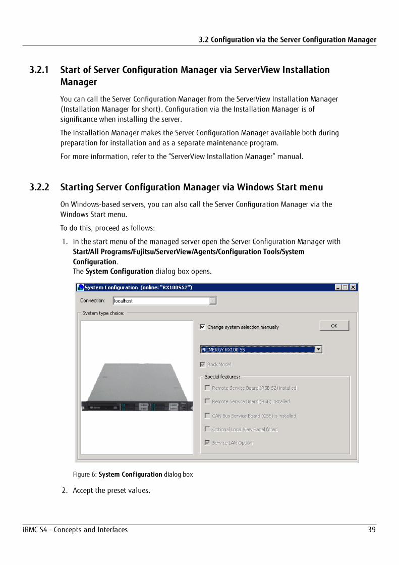
1. In the start menu of the managed server open the Server Configuration Manager withStart/All Programs/Fujitsu/ServerView/Agents/Configuration Tools/SystemConfiguration.The System Configuration dialog box opens.
Figure 6: System Configuration dialog box
2. Accept the preset values.
iRMC S4 - Concepts and Interfaces 39
3.2 Configuration via the Server Configuration Manager
3. Click OK.The tab view of the System Configuration dialog box opens.
You can scroll to the left and right through the tabs by clicking the arrows next to thetabs.
Applying settings
To apply the settings made in the individual tabs, proceed as follows for each tab:
1. Click the Apply button.
2. Click the Save Page button.
The iRMC automatically reboots to activate the changed settings.
3.2.3 Starting Server Configuration Manager via Operations Manager
You can start the Server Configuration Manager to configure the iRMC also from thegraphical user interface of the Operations Manager. This allows you to configure the iRMCof the managed server from the remote workstation via a web interface.
Proceed as follows:
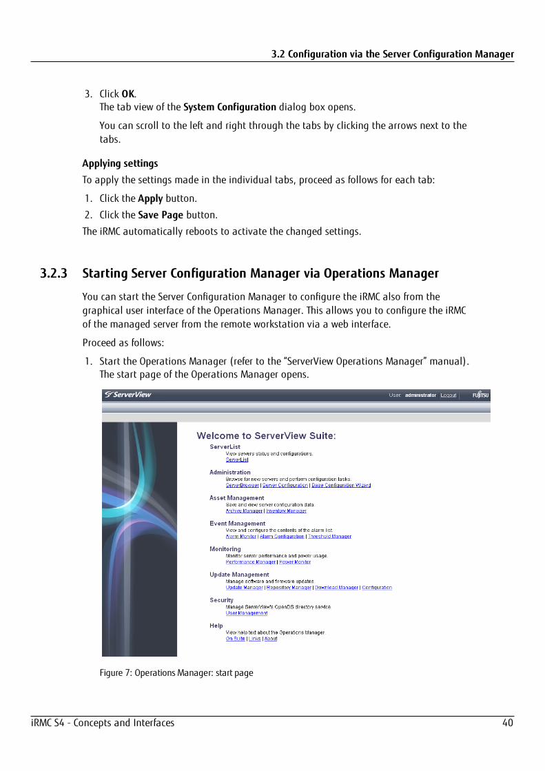
1. Start the Operations Manager (refer to the “ServerView Operations Manager” manual).The start page of the Operations Manager opens.
Figure 7: Operations Manager: start page
iRMC S4 - Concepts and Interfaces 40
3.2 Configuration via the Server Configuration Manager
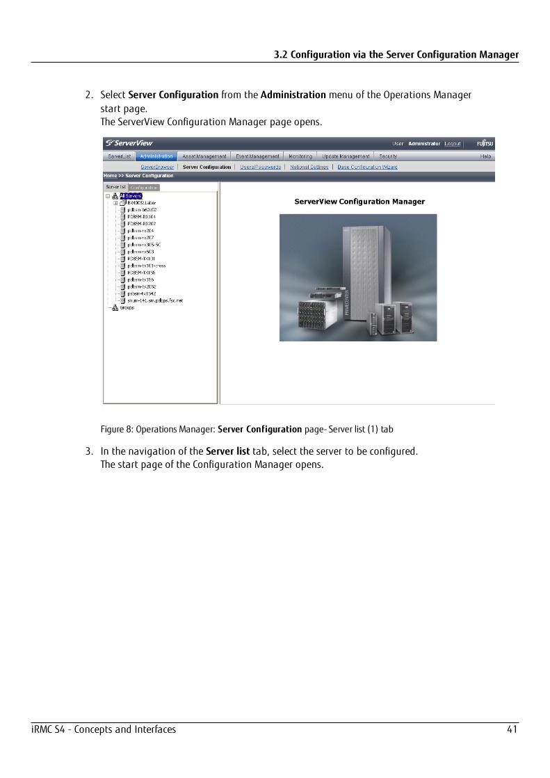
2. Select Server Configuration from the Administration menu of the Operations Managerstart page.The ServerView Configuration Manager page opens.
Figure 8: Operations Manager: Server Configuration page- Server list (1) tab
3. In the navigation of the Server list tab, select the server to be configured.The start page of the Configuration Manager opens.
iRMC S4 - Concepts and Interfaces 41

3.3 Configuration via Remote Manager
Figure 9: Operations Manager: Server Configuration page- Server list (2) tab
4. On the right-hand side of the page, specify the details of the selected server andconfirm your entries by clicking GO.The first dialog box of the Server Configuration Manager opens.
3.3 Configuration via Remote ManagerThe Remote Manager is a Telnet-based interface of the iRMC. You can call the RemoteManager over any Telnet/SSH client.
The iRMC supports secure connections over SSH. The Remote Manager interface is identicalfor Telnet and SSH connections.
In principle, any Telnet/SSH client that interprets VT100 sequences can be used to accessthe iRMC. It is nevertheless recommended that the iRMC web interface or the ServerViewRemote Management Front end is used.
See "Configuration via Telnet/SSH (Remote Manager)" on page 51 for more details.
iRMC S4 - Concepts and Interfaces 42

3.4 Configuration via the Remote Manager (Serial) interface
3.4 Configuration via the Remote Manager (Serial) interfaceIf you connect a computer over a null modem cable and start a terminal program(VT100+) on this computer, you can access the Remote Manager (Serial) terminalprogram. The Remote Manager (Serial) interface is identical to the Remote Managerinterface.
Prerequisite
On the managed server the Serial Multiplexer BIOS setting on the iRMC is configured.
Terminal program (VT100+):
Configure the following port settings for the terminal program:
Bits per secondSet the value to 38400.
Data bitsSet the value to 8.
ParitySet the value to None.
Stop bitsSet the value to 1.
Flow ControlSet the value to None.
3.5 Configuration via text console redirectionText console redirection will be available depending on the configuration of text consoleredirection and on the operating system of the server:
l Either for the duration of the BIOS POST phase only or
l Beyond the BIOS POST phase while the operating system is running
You configure the text console redirection via LAN with the UEFI setup utility.
Windows Server 2008 / 2012
If activated during Windows installation, console redirection is therebyautomatically configured.
If console redirection is activated after Windows installation has completed, you mustconfigure console redirection manually.
iRMC S4 - Concepts and Interfaces 43
3.6 Configuration via scripting
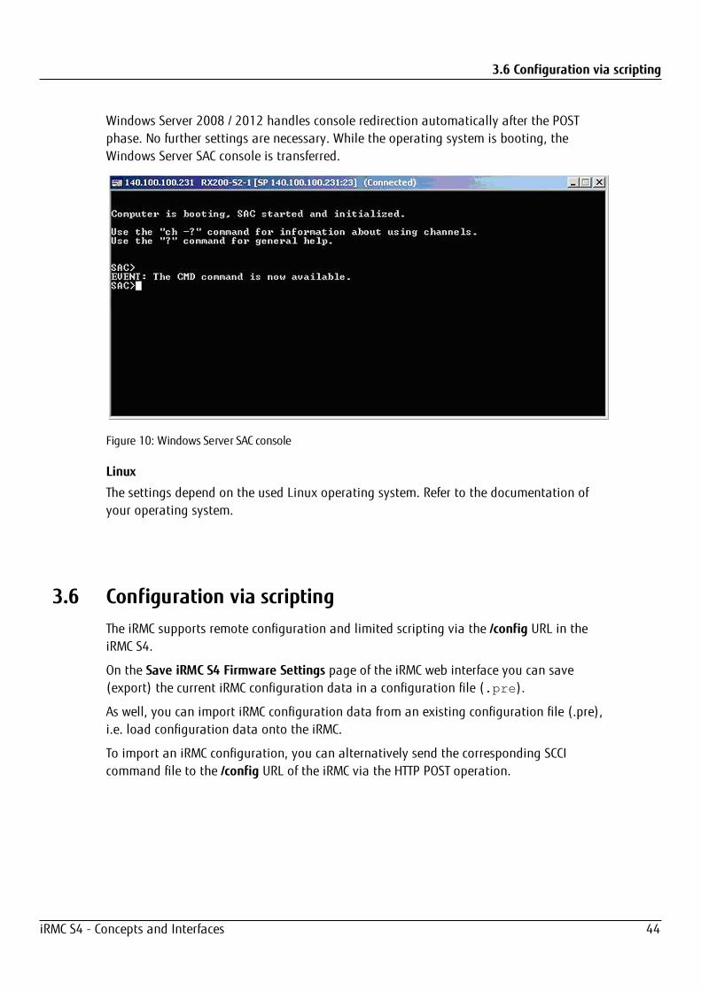
Windows Server 2008 / 2012 handles console redirection automatically after the POSTphase. No further settings are necessary. While the operating system is booting, theWindows Server SAC console is transferred.
Figure 10: Windows Server SAC console
Linux
The settings depend on the used Linux operating system. Refer to the documentation ofyour operating system.
3.6 Configuration via scriptingThe iRMC supports remote configuration and limited scripting via the /config URL in theiRMC S4.
On the Save iRMC S4 Firmware Settings page of the iRMC web interface you can save(export) the current iRMC configuration data in a configuration file (.pre).
As well, you can import iRMC configuration data from an existing configuration file (.pre),i.e. load configuration data onto the iRMC.
To import an iRMC configuration, you can alternatively send the corresponding SCCIcommand file to the /config URL of the iRMC via the HTTP POST operation.
iRMC S4 - Concepts and Interfaces 44

3.7 Configuration via UEFI setup utility
You can import configuration files via the SCCI API using commands of the followinglanguages:
l cURL
l VB script
l Python
For more information, refer to "Configuration via scripting" on page 69.
3.7 Configuration via UEFI setup utilityUEFI (Unified Extensible Firmware Interface) is a standard firmware interface for PCs pre-installed with Windows 8 and newer, which is designed to replace BIOS.
By default, a Windows 8 shutdown is not a real shutdown but a hybrid shutdown wherecontents of the memory are saved to disk. This allows for a faster startup. However,turning on the PC after a hybrid shutdown does not allow for pressing F1 or F12 duringstartup.
There are several ways to enter Setup Utility (F1) or the Boot Menu (F12) on a MicrosoftWindows 8 PC:
l Press and hold the Shift key while selecting the Shutdown option in Windows 8. Thiswill make the PC perform a full shutdown instead of a hybrid shutdown. Then F1 orF12 can be pressed successfully during startup.
l Select Restart instead of Shutdown. Then F1 or F12 can be pressed successfully duringstartup.
l Disable the fast startup option in Control Panel -> Hardware and Sound -> PowerOptions -> Choose what the power buttons do.
iRMC S4 - Concepts and Interfaces 45
3.7 Configuration via UEFI setup utility
3.7.1 Configuring the LAN interface
You can configure the iRMC’s LAN interface using the UEFI setup utility:
1. Call the UEFI setup utility of the managed server.
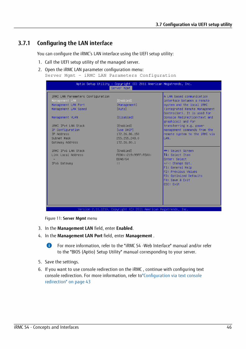
2. Open the iRMC LAN parameter configuration menu:Server Mgmt – iRMC LAN Parameters Configuration
Figure 11: Server Mgmtmenu
3. In the Management LAN field, enter Enabled.
4. In the Management LAN Port field, enter Management .
For more information, refer to the "iRMC S4 -Web Interface" manual and/or referto the "BIOS (Aptio) Setup Utility" manual corresponding to your server.
5. Save the settings.
6. If you want to use console redirection on the iRMC , continue with configuring textconsole redirection. For more information, refer to"Configuration via text consoleredirection" on page 43
iRMC S4 - Concepts and Interfaces 46
3.7 Configuration via UEFI setup utility
7. If you do not want to use text console redirection on the iRMC, exit the UEFI setup andcontinue with testing the LAN interface. (For more information, refer tothe "iRMC S4 -Configuration and Maintenance" manual)
3.7.2 Configuring text console redirection
1. Call the UEFI setup utility of the managed server.
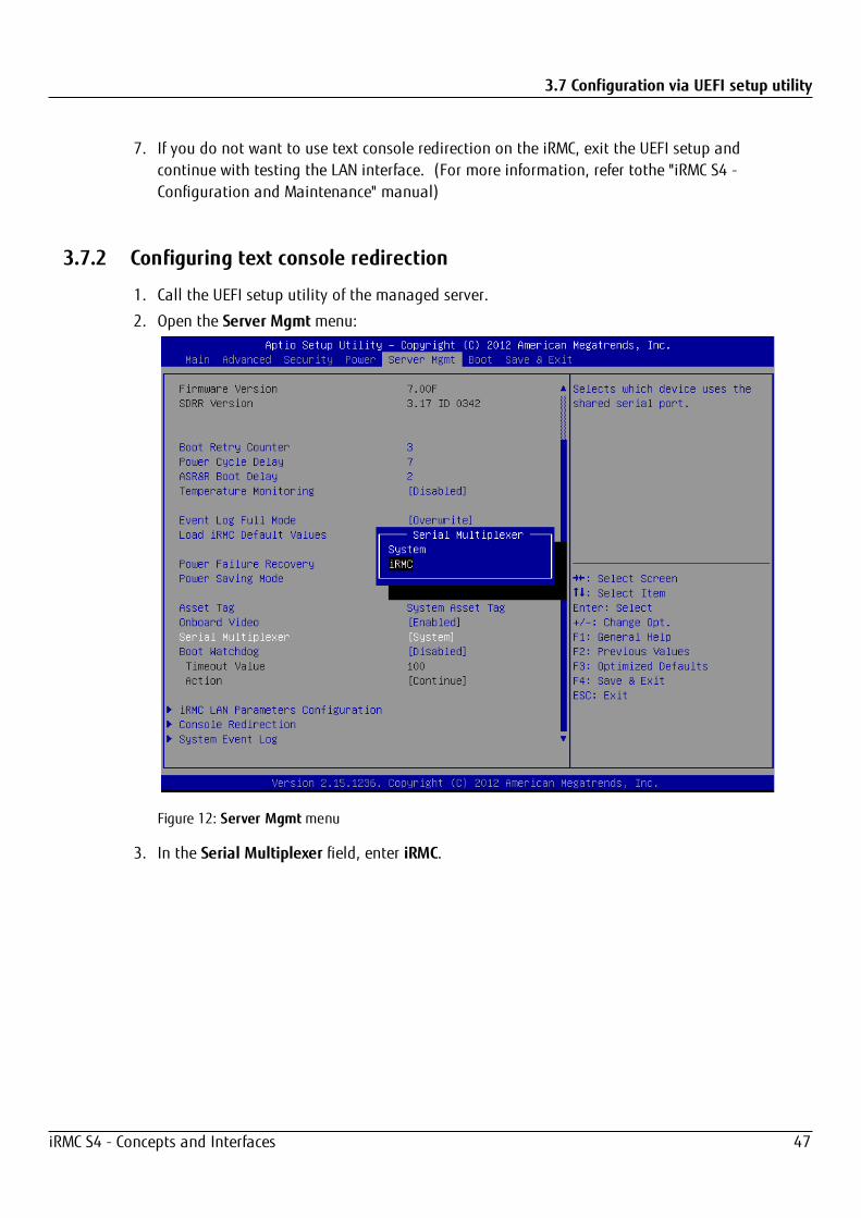
2. Open the Server Mgmtmenu:
Figure 12: Server Mgmtmenu
3. In the Serial Multiplexer field, enter iRMC.
iRMC S4 - Concepts and Interfaces 47
3.7 Configuration via UEFI setup utility
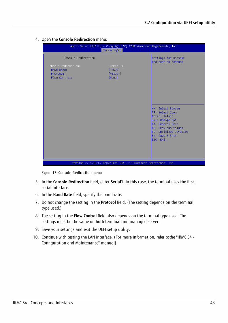
4. Open the Console Redirection menu:
Figure 13: Console Redirection menu
5. In the Console Redirection field, enter Serial1. In this case, the terminal uses the firstserial interface.
6. In the Baud Rate field, specify the baud rate.
7. Do not change the setting in the Protocol field. (The setting depends on the terminaltype used.)
8. The setting in the Flow Control field also depends on the terminal type used. Thesettings must be the same on both terminal and managed server.
9. Save your settings and exit the UEFI setup utility.
10. Continue with testing the LAN interface. (For more information, refer tothe "iRMC S4 -Configuration and Maintenance" manual)
iRMC S4 - Concepts and Interfaces 48
3.7 Configuration via UEFI setup utility
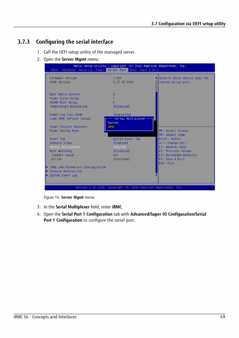
3.7.3 Configuring the serial interface
1. Call the UEFI setup utility of the managed server.
2. Open the Server Mgmtmenu:
Figure 14: Server Mgmtmenu
3. In the Serial Multiplexer field, enter iRMC.
4. Open the Serial Port 1 Configuration tab with Advanced/Super IO Configuration/SerialPort 1 Configuration to configure the serial port.
iRMC S4 - Concepts and Interfaces 49

3.7 Configuration via UEFI setup utility
Figure 15: Serial Port 1 Configuration tab
5. In the Serial Port field, enter Enabled.
6. Save your settings and exit the UEFI setup utility.
7. Continue with testing the LAN interface. (For more information, refer to the "iRMC S4 -Configuration and Maintenance " manual).
iRMC S4 - Concepts and Interfaces 50

4 Configuration via Telnet/SSH (Remote Manager)A Telnet-based interface is available for the iRMC. This is known as the Remote Manager.You can call the Remote Manager over any Telnet/SSH client.
The iRMC supports secure connections over SSH (Secure Shell). The Remote Managerinterface is identical for Telnet and SSH connections. In principle, any Telnet/SSH client thatinterprets VT100 sequences can be used to access the iRMC. It is neverthelessrecommended that the iRMC web interface or the ServerView Remote Management Frontend (referred to below simply as the Remote Management Front end) be used.
This chapter describes operation of the iRMC from the Remote Manager and the variousfunctions in detail. The end of the chapter also provides a brief overview of SMASH CLP.
4.1 Requirements on the managed serverAccess via Telnet must be activated for the iRMC (for more information, refer to the section"Ports and Network Services - Configuring ports and network services" in the "iRMC S4 -Web Interface" manual.).
Access via the Telnet protocol is deactivated by default for security reasons, aspasswords are transmitted in plain text.
Since the ServerView Operations Manager does not know the value of the managementport, the Remote Management Front-end works with the default value.
Since a connection is not automatically established when the Remote ManagementFront-end is started, you can correct any nonstandard value for the management portafter the Remote Management Front-end has been started.
iRMC S4 - Concepts and Interfaces 51
4.2Re
quire
duser
perm
ission
s
4.2
Requ
ireduser
perm
ission
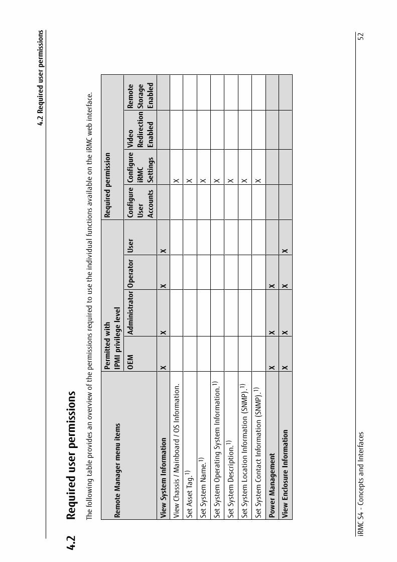
sThefollo
wingtableprovides
anoverview
oftheperm
ission
srequ
iredto
usetheindividu
alfunctio
nsavailableon
theiRMCweb
interfa
ce.
RemoteMan
ager
men
uite
ms
Perm
itted
with
IPMIp
rivile
gelevel
Requ
iredpe
rmission
OEM
Administrator
Ope
rator
User
Configure
User
Accoun
ts
Configure
iRMC
Settings
Vide
oRe
direction
Enab
led
Remote
Storag
eEn
abled
View
System
Inform
ation
XX
XX
View
Chassis/M
ainb
oard
/OSInform
ation.
X
SetA
sset
Tag.1)
X
SetS
ystem
Name.1)
X
SetS
ystem
OperatingSystem
Inform
ation.1)
X
SetS
ystem
Descrip
tion.1)
X
SetS
ystem
Locatio
nInform
ation(SNM
P).1)
X
SetS
ystem
ContactInformation(SNM
P).1)
X
Power
Man
agem
ent
XX
X
View
EnclosureInform
ation
XX
XX
iRMCS4
-Con
ceptsan
dInterfa
ces
52

4.2Re
quire
duser
perm
ission
s
RemoteMan
ager
men
uite
ms
Perm
itted
with
IPMIp
rivile
gelevel
Requ
iredpe
rmission
OEM
Administrator
Ope
rator
User
Configure
User
Accoun
ts
Configure
iRMC
Settings
Vide
oRe
direction
Enab
led
Remote
Storag
eEn
abled
System
Eventlo
g-V
iew/Dum
pSystem
Eventlo
g.X
XX
X
System
Eventlo
g-C
lear
System
Eventlo
g.X
XX
Internal
Eventlo
g-V
iew/Dum
pInternal
Eventlo
g.X
XX
XX
Internal
Eventlo
g-C
lear
Internal
Eventlo
g.X
XX
XX
Sensor
overview
s(Tem
perature,Fan
s...)
XX
XX
View
ServiceProcessor
XX
XX
ServiceProcessor-
ListIP
Parameters.
X
ServiceProcessor-
ConfigureIP
Parameters.
X
ServiceProcessor-
Togg
leIdentifyLED.
XX
XX
ServiceProc.-
ResetiRM
CS4
(warm/cold
reset).
XX
X
Raid
Man
agem
ent
XX
View
Controllerinformation.2)
XX
View
physical
device
inform
ation.2)
XX
iRMCS4
-Con
ceptsan
dInterfa
ces
53
4.2Re
quire
duser
perm
ission
s
RemoteMan
ager
men
uite
ms
Perm
itted
with
IPMIp
rivile
gelevel
Requ
iredpe
rmission
OEM
Administrator
Ope
rator
User
Configure
User
Accoun
ts
Configure
iRMC
Settings
Vide
oRe
direction
Enab
led
Remote
Storag
eEn
abled
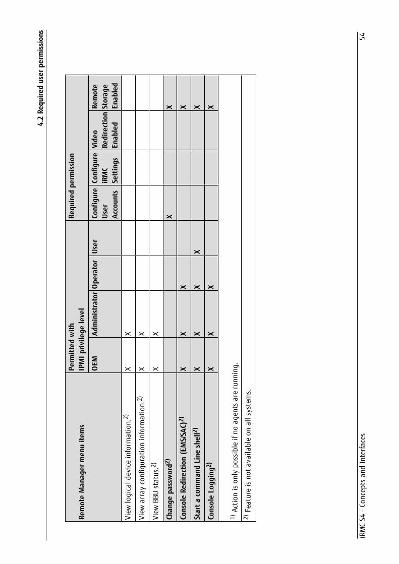
View
logicald
eviceinform
ation.2)
XX
View
arrayconfigurationinform
ation.2)
XX
View
BBUstatus.2)
XX
Chan
gepa
ssword2
)X
X
ConsoleRe
direction(EMS/SA
C)2)
XX
XX
Starta
comman
dLine
shell2)
XX
XX
X
ConsoleLogg
ing2
)X
XX
X
1)Actio
nison
lypo
ssibleifno
agentsarerunn
ing.
2)Featureisno
tavaila
bleon
allsystems.
iRMCS4
-Con
ceptsan
dInterfa
ces
54
4.3 Logging in
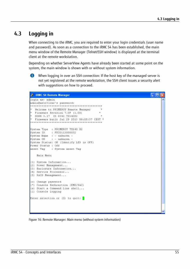
4.3 Logging inWhen connecting to the iRMC, you are required to enter your login credentials (user nameand password). As soon as a connection to the iRMC S4 has been established, the mainmenu window of the Remote Manager (Telnet/SSH window) is displayed at the terminalclient at the remote workstation.
Depending on whether ServerView Agents have already been started at some point on thesystem, the main window is shown with or without system information.
When logging in over an SSH connection: If the host key of the managed server isnot yet registered at the remote workstation, the SSH client issues a security alertwith suggestions on how to proceed.
Figure 16: Remote Manager: Main menu (without system information)
iRMC S4 - Concepts and Interfaces 55
4.4 Main menu
The Remote Manager window contains information on the affected system. Thisinformation identifies the server and indicates its operating status (Power Status). Somedetails (e.g. the System Name) are only shown for servers and only if the server isconfigured appropriately.
In order to be able to use the Remote Manager, you must log in with a user name and apassword.
Then an appropriate event will be written to the Event log and the relevant main menu ofthe Remote Manager displayed (for more information, refer tosection "Main menu of theRemote Manager").
You can terminate the login process at any time using [Ctrl] + [D].
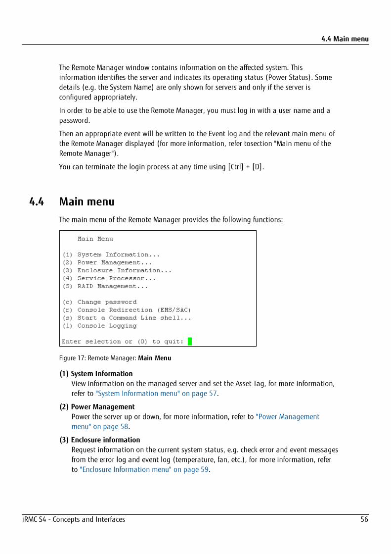
4.4 Main menuThe main menu of the Remote Manager provides the following functions:
Figure 17: Remote Manager: Main Menu
(1) System InformationView information on the managed server and set the Asset Tag, for more information,refer to "System Information menu" on page 57.
(2) Power ManagementPower the server up or down, for more information, refer to "Power Managementmenu" on page 58.
(3) Enclosure informationRequest information on the current system status, e.g. check error and event messagesfrom the error log and event log (temperature, fan, etc.), for more information, referto "Enclosure Information menu" on page 59.
iRMC S4 - Concepts and Interfaces 56
4.4 Main menu
(4) Service ProcessorConfigure the iRMC (e.g. update firmware or change IP address), for more information,refer to "Service processor menu" on page 62.
(5) RAID ManagementInformation on RAID controllers, physical and logical devices, array configuration andBBU status, for more information, refer to "RAID Management menu" on page 63.
(c) Change passwordChange the password.
(r) Console Redirection (EMS/SAC)Text console redirection, for more information, refer to "Console Redirection (EMS/SAC)"on page 63.
(s) Start a Command Line shellStart a Command Line shell, for more information, refer to "Shell menu" on page 64.
(l) Console loggingRedirect output of messages to the text console, for more information, refer to"Console Logging" on page 64.
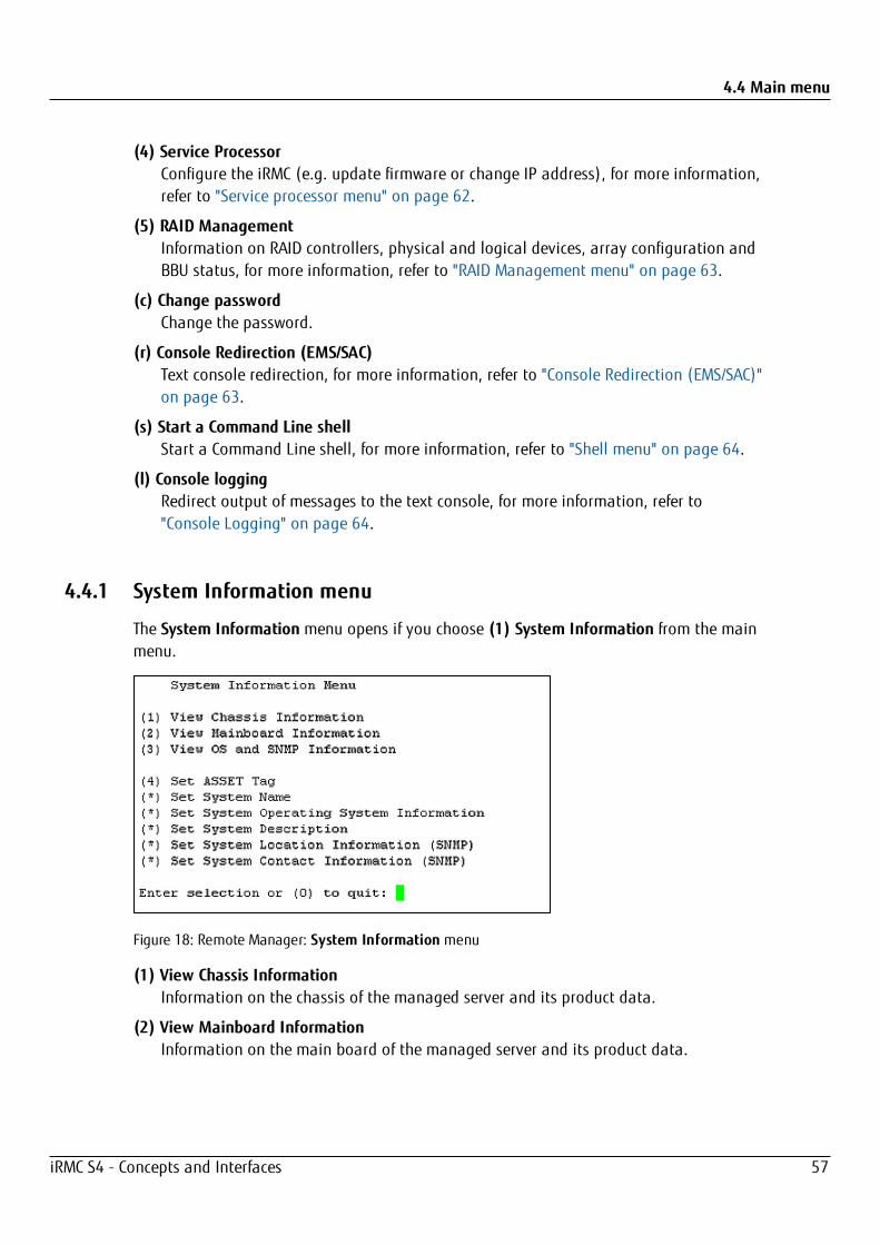
4.4.1 System Information menu
The System Information menu opens if you choose (1) System Information from the mainmenu.
Figure 18: Remote Manager: System Information menu
(1) View Chassis InformationInformation on the chassis of the managed server and its product data.
(2) View Mainboard InformationInformation on the main board of the managed server and its product data.
iRMC S4 - Concepts and Interfaces 57

4.4 Main menu
(3) View OS and SNMP InformationInformation on the operating system and the ServerView version of the managedserver and on the SNMP settings.
(4) Set ASSET TagSets a customer-specific asset tag for the managed server.
4.4.2 Power Management menu
The Power Managementmenu opens if you choose (2) Power Management from themain menu.
Figure 19: Remote Manager: Power Managementmenu
(1) Immediate Power OffPowers the server down, regardless of the status of the operating system.
(2) Immediate ResetCompletely restarts the server (cold start), regardless of the status of the operatingsystem.
(3) Power CyclePowers the server down completely and then powers it up again after a configuredperiod.
(*) Power OnSwitches the server on.
(5) Graceful Power Off (Shutdown)Graceful shutdown and power off.
This menu item is only available if ServerView Agents are installed and signed ontothe iRMC S4 as “Connected”.
This command can not be executed on servers running the ESXi operating system.
iRMC S4 - Concepts and Interfaces 58
4.4 Main menu
(6) Graceful Reset (Reboot)Graceful shutdown and reboot.
This menu item is only available if ServerView Agents are installed and signed ontothe iRMC S4 as “Connected”.
This command can not be executed on servers running the ESXi operating system.
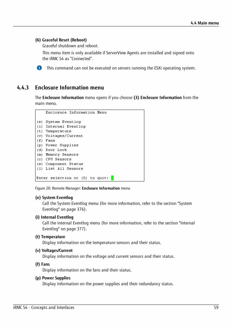
4.4.3 Enclosure Information menu
The Enclosure Information menu opens if you choose (3) Enclosure Information from themain menu.
Figure 20: Remote Manager: Enclosure Information menu
(e) System EventlogCall the System Eventlog menu (for more information, refer to the section "SystemEventlog" on page 376).
(i) Internal EventlogCall the internal Eventlog menu (for more information, refer to the section "InternalEventlog" on page 377).
(t) TemperatureDisplay information on the temperature sensors and their status.
(v) Voltages/CurrentDisplay information on the voltage and current sensors and their status.
(f) FansDisplay information on the fans and their status.
(p) Power SuppliesDisplay information on the power supplies and their redundancy status.
iRMC S4 - Concepts and Interfaces 59
4.4 Main menu
(d) Door LockDisplay information on whether the front panel or housing are open.
(m) Memory SensorsDisplay information on the memory statuses.
(c) CPU SensorsLocalize the processors of the server.
(s) Component StatusDisplay detailed information on all sensors that have a PRIMERGY diagnostic LED.
(l) List All SensorsDisplay detailed information on all sensors.
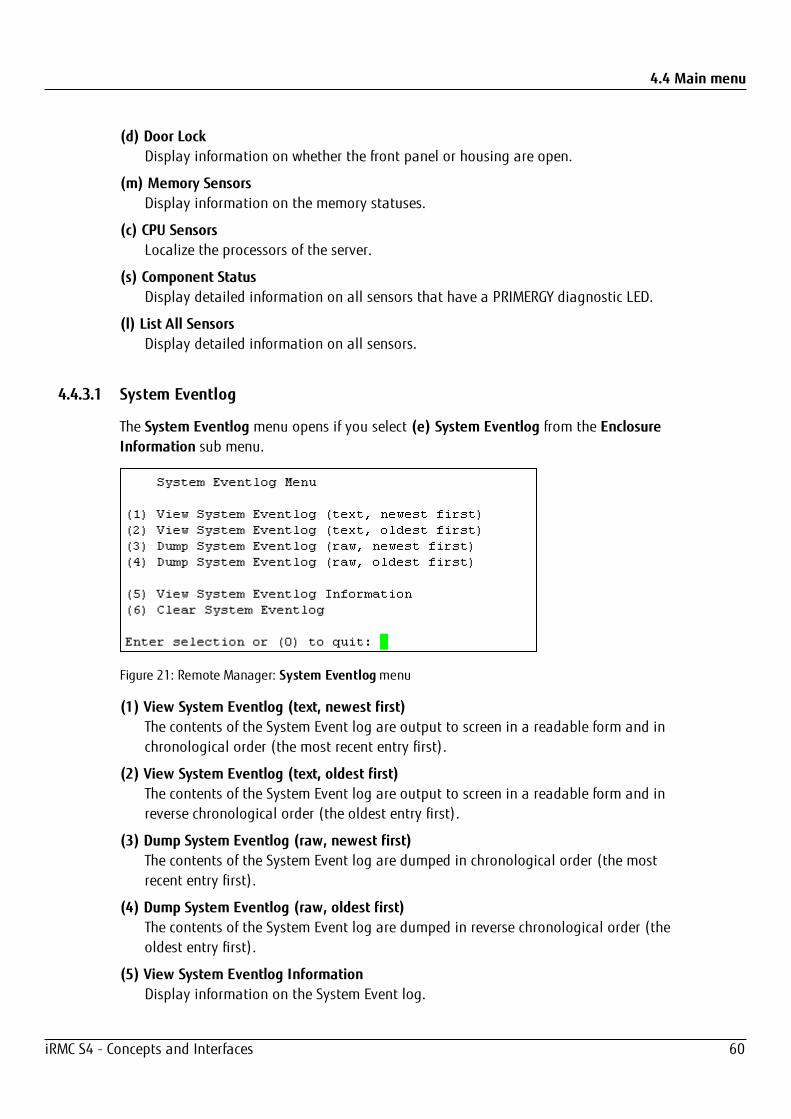
4.4.3.1 System Eventlog
The System Eventlog menu opens if you select (e) System Eventlog from the EnclosureInformation sub menu.
Figure 21: Remote Manager: System Eventlogmenu
(1) View System Eventlog (text, newest first)The contents of the System Event log are output to screen in a readable form and inchronological order (the most recent entry first).
(2) View System Eventlog (text, oldest first)The contents of the System Event log are output to screen in a readable form and inreverse chronological order (the oldest entry first).
(3) Dump System Eventlog (raw, newest first)The contents of the System Event log are dumped in chronological order (the mostrecent entry first).
(4) Dump System Eventlog (raw, oldest first)The contents of the System Event log are dumped in reverse chronological order (theoldest entry first).
(5) View System Eventlog InformationDisplay information on the System Event log.
iRMC S4 - Concepts and Interfaces 60
4.4 Main menu
(6) Clear System EventlogClear the contents of the System Event log.
(7) Change System Eventlog modeChanges the buffer mode of the System Event Log from Ring Buffer mode to LinearBuffer mode and vice versa.
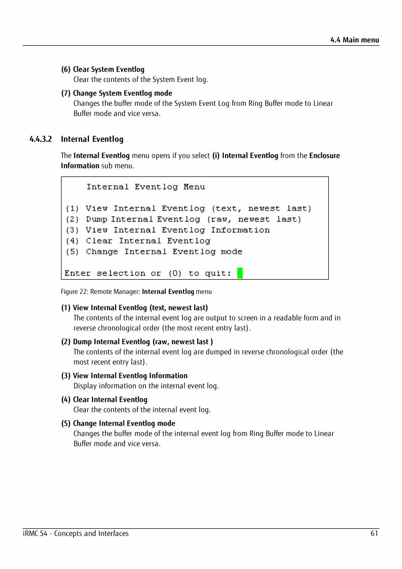
4.4.3.2 Internal Eventlog
The Internal Eventlog menu opens if you select (i) Internal Eventlog from the EnclosureInformation sub menu.
Figure 22: Remote Manager: Internal Eventlogmenu
(1) View Internal Eventlog (text, newest last)The contents of the internal event log are output to screen in a readable form and inreverse chronological order (the most recent entry last).
(2) Dump Internal Eventlog (raw, newest last )The contents of the internal event log are dumped in reverse chronological order (themost recent entry last).
(3) View Internal Eventlog InformationDisplay information on the internal event log.
(4) Clear Internal EventlogClear the contents of the internal event log.
(5) Change Internal Eventlog modeChanges the buffer mode of the internal event log from Ring Buffer mode to LinearBuffer mode and vice versa.
iRMC S4 - Concepts and Interfaces 61

4.4 Main menu
4.4.4 Service processor menu
The Service processor menu opens if you choose (4) Service Processor from the mainmenu.
Figure 23: Remote Manager: Service Processor menu
(1) Configure IP ParametersConfigure the IPv4/IPv6 address settings of the iRMC in a guided dialog. Refer tosection "Network Interface Setting" in the "iRMC S4 - Web Interface" manual for detailson the individual settings.
(2) List IP ParametersDisplay the IP settings.
(3) Toggle Identify LEDSwitch the PRIMERGY identification LED on/off.
(4) Reset iRMC S4 (Warm reset)Reset the iRMC. The connection is closed.
Only the interfaces are re-initialized.
(5) Reset iRMC S4 (Cold reset)Reset the iRMC. The connection is closed.
The entire iRMC is re-initialized.
It is recommended to reboot the server after a Reset iRMC S4 (Cold Reset) or ResetiRMC S4 (Warm Reset).
iRMC S4 - Concepts and Interfaces 62
4.4 Main menu
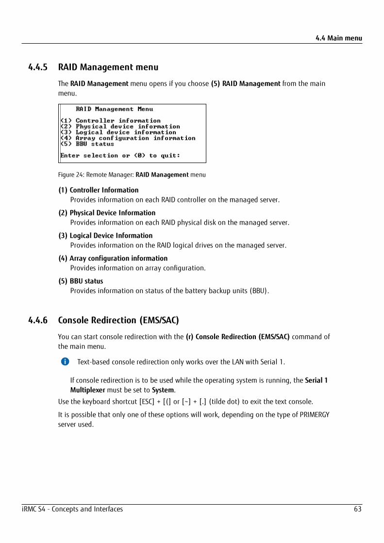
4.4.5 RAID Management menu
The RAID Managementmenu opens if you choose (5) RAID Management from the mainmenu.
Figure 24: Remote Manager: RAID Managementmenu
(1) Controller InformationProvides information on each RAID controller on the managed server.
(2) Physical Device InformationProvides information on each RAID physical disk on the managed server.
(3) Logical Device InformationProvides information on the RAID logical drives on the managed server.
(4) Array configuration informationProvides information on array configuration.
(5) BBU statusProvides information on status of the battery backup units (BBU).
4.4.6 Console Redirection (EMS/SAC)
You can start console redirection with the (r) Console Redirection (EMS/SAC) command ofthe main menu.
Text-based console redirection only works over the LAN with Serial 1.
If console redirection is to be used while the operating system is running, the Serial 1Multiplexer must be set to System.
Use the keyboard shortcut [ESC] + [(] or [~] + [.] (tilde dot) to exit the text console.
It is possible that only one of these options will work, depending on the type of PRIMERGYserver used.
iRMC S4 - Concepts and Interfaces 63
4.4 Main menu
4.4.7 Shell menu
(s) Start a Command Line shell in the main menu opens the Shell Menu in which you canstart a SMASH CLP shell. SMASH CLP stands for Systems Management Architecture forServer Hardware Command Line Protocol. This protocol permits a Telnet- or SSH-basedconnection between the management station and the managed server.
For further details on SMASH CLP, refer to "Command Line Protocol" on page 66.
Figure 25: Remote Manager: Shell Menu
1. Enter 1 to start the SMASH CLP shell.
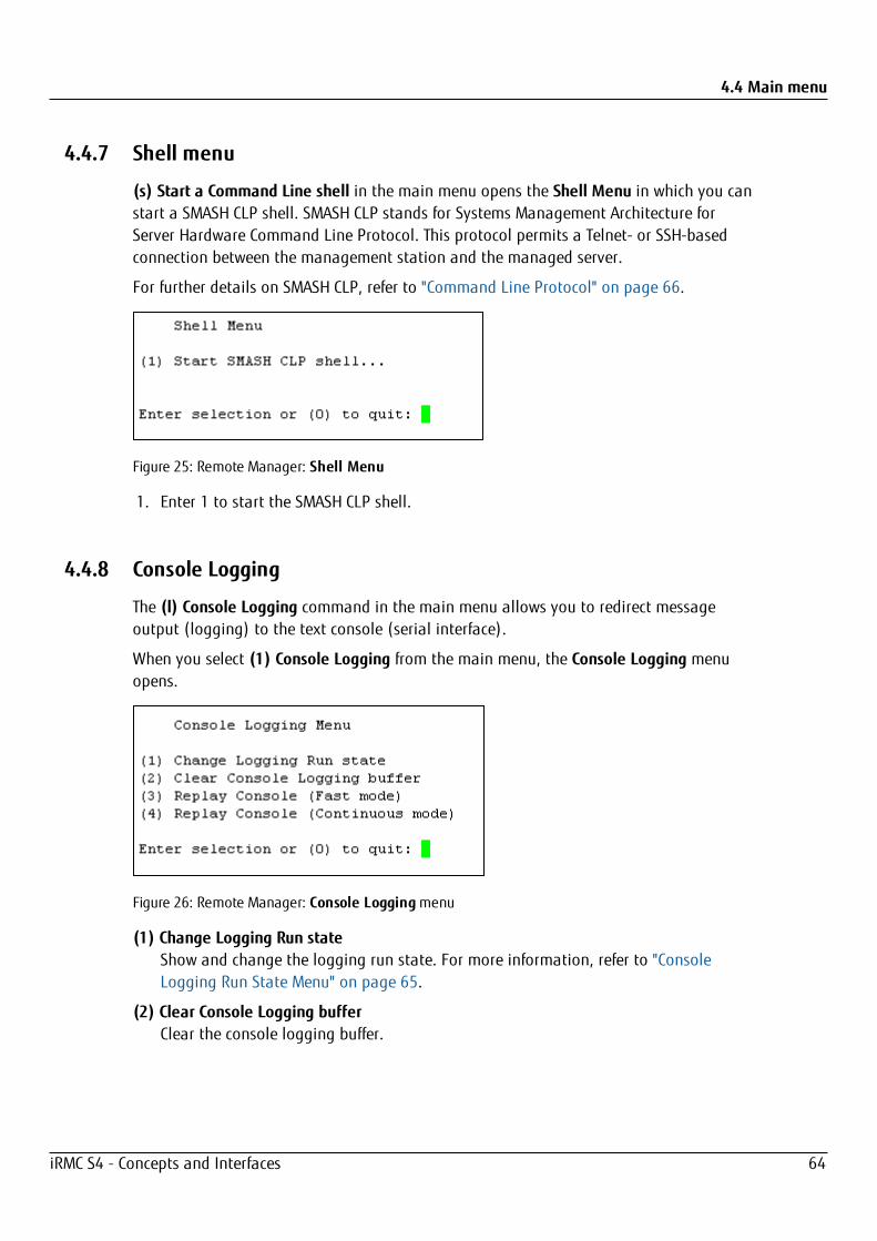
4.4.8 Console Logging
The (l) Console Logging command in the main menu allows you to redirect messageoutput (logging) to the text console (serial interface).
When you select (1) Console Logging from the main menu, the Console Logging menuopens.
Figure 26: Remote Manager: Console Loggingmenu
(1) Change Logging Run stateShow and change the logging run state. For more information, refer to "ConsoleLogging Run State Menu" on page 65.
(2) Clear Console Logging bufferClear the console logging buffer.
iRMC S4 - Concepts and Interfaces 64
4.4 Main menu
(3) Replay Console (Fast mode)Show the console log (in fast mode).
(4) Replay Console (Continuous mode)Show the console log (in continuous mode).
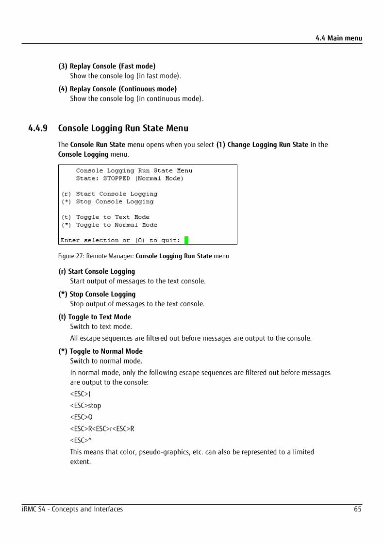
4.4.9 Console Logging Run State Menu
The Console Run State menu opens when you select (1) Change Logging Run State in theConsole Logging menu.
Figure 27: Remote Manager: Console Logging Run Statemenu
(r) Start Console LoggingStart output of messages to the text console.
(*) Stop Console LoggingStop output of messages to the text console.
(t) Toggle to Text ModeSwitch to text mode.
All escape sequences are filtered out before messages are output to the console.
(*) Toggle to Normal ModeSwitch to normal mode.
In normal mode, only the following escape sequences are filtered out before messagesare output to the console:
<ESC>(
<ESC>stop
<ESC>Q
<ESC>R<ESC>r<ESC>R
<ESC>^
This means that color, pseudo-graphics, etc. can also be represented to a limitedextent.
iRMC S4 - Concepts and Interfaces 65
4.5 Command Line Protocol
4.5 Command Line ProtocolThe iRMC supports various text-based user interfaces, known as user shells, which can beconfigured differently for individual users.
The System Management Architecture for Server Hardware (SMASH) initiative defines anumber of specifications with the following objectives:
l Provision of standardized interfaces for managing heterogeneous computerenvironments.
l Provision of an architecture framework with uniform interfaces, hardware and softwarediscovery, resource addressing and data models.
You can find further information on SMASH under the following link:http://www.dmtf.org/standards/smash
SMASH CLP syntax
SMASH CLP specifies a common command line syntax and message protocol semantics formanaging computers on the Internet and in enterprise and service provider environments.You can find detailed information on SMASH CLP in the DMTF document “ServerManagement Command Line Protocol Specification (SM CLP) DSP0214”.
The general syntax of the CLP is as follows:
<verb> [<options>] [<target>] [<properties>]
<verb>Verbs specify the command or action to be executed. The list of verbs describes thefollowing activities, for instance:
l Establish (set) and retrieve (show) data
l Change the status of a target (reset, start, stop)
l Manage the current session (cd, version, exit)
l Return information on commands (help)
In iRMC systems, the verb oemfujitsu also allows the use of special OEMcommands.
<options>Command options modify the action or the behavior of a verb. Options canimmediately follow the verb in a command line and must always be introduced by adash ("-").
Options allow you to, for instance:
l Define the output format
l Permit recursive execution of a command
l Display the version of a command
l Request help
iRMC S4 - Concepts and Interfaces 66

4.5 Command Line Protocol
<target><target> specifies the address or the path of the object to be manipulated by thecommand, i.e. the target of the command. This can be a single managed element suchas a hard disk, a network adapter (Network Interface Card, NIC), or the managementprogram (Management Assistance Program, MAP) itself. Targets can, however, also beservices such as a transport service.
Several managed elements which can be managed by the management program canbe subsumed under a single <target>, for instance the entire system.
Only one <target> may be specified for each command.
<properties><properties> describe the properties of the target of the command which are requiredto execute the command. Thus, <properties> identify the properties of the target’sclass that are to be retrieved or modified by the command.
User data in the CLP (overview)
Data within the CLP is structured hierarchically. The command cd allows you to navigatewithin this structure.
Hierarchy of the CLP commands
An overview of the CLP command hierarchy is shown in the following table:
iRMC S4 - Concepts and Interfaces 67
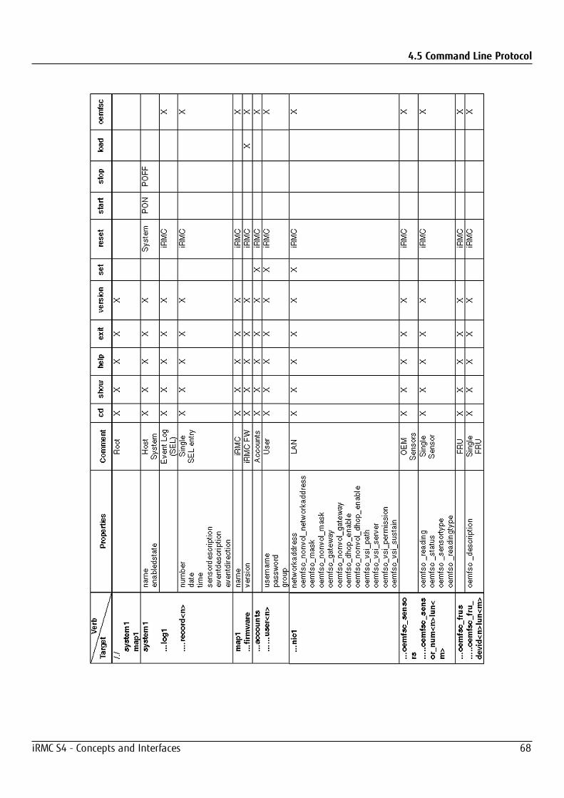
4.5 Command Line Protocol
iRMC S4 - Concepts and Interfaces 68

5 Configuration via scriptingThe iRMC S4 supports the following APIs for scripted configuration:
l RESTful
l CIM
l SCCI
Thus you can configure a bunch of managed servers with one script in one roll out.
The system report of the iRMC provides information about the current settings and HWfittings.
5.1 RESTREST (Representational State Transfer) is a resource-oriented architecture (ROA) style thatdescribes how web standards can be used in a web-compatible manner, thus increasingthe reusability, extensibility, clarity, and simple integration of external systems into anexisting network structure of web services. In order to use the web browser to navigatefrom one resource to another, REST requires simple, clear, uniform interfaces. It is thereforenecessary to comply with certain specifications and be constrained by a particular set ofaccess methods (e.g. HTTP methods).
REST represents an alternative to web services that are based on a service-orientedarchitecture (SOA). If web services use the REST architecture, they are known as RESTfulAPIs (Application Programming Interfaces) or REST APIs. Unlike SOAP-based web services,there are no "official" standards for RESTful APIs. The reason for this is that REST is anarchitectural style, while SOAP is a protocol. Even if REST is not a standard in itself, RESTfulimplementations use standards such as HTTP, URI, JSON, and XML.
Each REST resource has a generic interface via the HTTP methods GET, POST, PUT, andDELETE. Log conventions are not required in order to enable a client and server tocommunicate with one another. Most application scenarios can be covered by these accessmethods.
In the case of resource-oriented web services (which also includes RESTful web services),messages are not sent to a fixed service endpoint. Instead, the recommended accessmethods (e.g. GET, PUT, POST, and DELETE) operate them directly on addressableresources.
The client's state changes each time information or resources are requested and modified.The term Representational State Transfer (REST) serves to visualize the transfer from an
iRMC S4 - Concepts and Interfaces 69
5.1 REST
application's current state to its next state. State transfers occur by transferring data thatwill represent the application's next state.
Resources are the basic components of a RESTful API. A resource must be addressable andhave at least one display form (representation). The request's header contains informationabout the type of client used and the representation required by this client. Each requestsent to the server must contain all information needed to interpret the request. The URI(uniform resource identifier/name and address of a resource) identifies the resource, whilethe HTTP header contains information such as the access type (e.g. GET), the return formator authentication. REST requires that the URI represents exactly one page of content andthat a REST server delivers the same web page content when it responds to multiplerequests with the same URI.
Links or URIs provide the client with a series of state transfers. The client is thereforemanaged intuitively by the application. In this context, it is important that each operationdelivers a status code and additional links. The provision of additional links in therespective representations enables other services to be integrated.
Depending on the application's request, various representations of a resource can bedelivered, for example, in different languages or formats (HTML, JSON or XML). HTTP statuscodes embed the access control at interface level. The user data does not have to be takeninto consideration – this supports service performance and complies with data protection.
The representation of a resource can also be chosen directly. The Content-Type attributemust be explicitly set in the HTTP header for this purpose. In the representation, it isimportant to specify which operations are permitted on a resource, and which are notpermitted.
Main features
The main features of the REST architectural style are listed below:
l Uniquely identifiable resources
l URIs or links for unique addressability
l Different representations of the resources, for example, in different languages orformats (HTML, JSON or XML)
The representation of a resource can refer to other resources. If a client followsa link in a representation, it changes from one state to another.
l Addressability
l Statelessness
A REST message contains all of the information required by the server or client in orderto understand the message. Neither the server nor the application saves stateinformation between two messages. This is known as a stateless protocol – eachoperation stands alone and is fully isolated from earlier operations.
iRMC S4 - Concepts and Interfaces 70
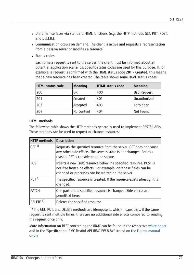
5.1 REST
l Uniform interfaces via standard HTML functions (e.g. the HTTP methods GET, PUT, POST,and DELETE).
l Communication occurs on demand. The client is active and requests a representationfrom a passive server or modifies a resource.
l Status codes
Each time a request is sent to the server, the client must be informed about allpotential application scenarios. Specific status codes are used for this purpose. If, forexample, a request is confirmed with the HTML status code 201 - Created, this meansthat a new resource has been created. The table shows some HTML status codes:
HTML status code Meaning HTML status code Meaning
200 OK 400 Bad Request
201 Created 401 Unauthorized
202 Accepted 403 Forbidden
204 No Content 404 Not Found
HTML methods
The following table shows the HTTP methods generally used to implement RESTful APIs.These methods can be used to request or change resources:
HTTP methods Description
GET 1) Requests the specified resource from the server. GET does not causeany other side effects. The server's state is not changed. For thisreason, GET is considered to be secure.
POST Inserts a new (sub)resource below the specified resource. POST isnot free from side effects. For example, database fields can bechanged or processes can be started on the server.
PUT 1) The specified resource is created. If the resource exists already, it ischanged.
PATCH One part of the specified resource is changed. Side effects arepermitted here.
DELETE 1) Deletes the specified resource.
1) The GET, PUT, and DELETE methods are idempotent, which means that, if the samerequest is sent multiple times, there are no additional side effects compared to sendingthe request once only.
More information on REST concerning the iRMC can be found in the respective white paperand in the "Specification iRMC Restful API iRMC FW 8.8x" stored on the Fujitsu manualserver.
iRMC S4 - Concepts and Interfaces 71

5.2 Profile Management
5.2 Profile ManagementUsing the profile management you can send and retrieve a full server configuration via theRESTful API.
Profile management supports the following functions:
l Create a profile (or sub profile) inside the iRMC’s profile store.
l Retrieve a profile (or sub profile) from the iRMC’s profile store.
l Apply a profile (or sub profile) to the iRMC to be executed.
l Get session information that provides status and log information for creating andapplying a profile.
l Control the version of a profile.
5.2.1 Profiles
A profile is a set of configuration parameters for a server and is available in XML or JSONformat.
The server profile contains the following sections, also called sub profiles.
SystemConfig
The SystemConfig section is divided into two sub profiles:
Sub profile Meaning
IrmcConfig Comprises the parameters of the iRMC configuration.
BiosConfig Comprises the parameters of the BIOS configuration.
AdapterIrmcConfig
Comprises the parameters of the virtualization configuration (according to Virtual IOManagement).
HWConfigurationIrmc
Comprises the parameters of the out-of-band RAID configuration.
When you use the eLCM Service Platform support the following additional sub profiles areavailable to allow an unattended deployment process:
HWConfiguration
Comprises the parameters of the RAID and LAN adapter configuration.
OSInstallation
Comprises the parameters of OS installation and deployment configuration.
iRMC S4 - Concepts and Interfaces 72
5.2 Profile Management
The iRMC advertises the currently supported version of the profile to enable profileadministration by the clients. Furthermore, each sub profile has its own version withmajor and minor information.
The iRMC accepts all profiles with the same major number and the same or lower minornumber. In these cases backward compatibility is ensured.
For further information on using profile management via the RESTful API of the iRMC referto the “iRMC S4 RESTful API Firmware 8.8” specification.
For further information on the Service Platform support refer to the “eLCM Overview” userguide.
5.2.2 Automatic BIOS parameter backup
To create a BiosConfig sub profile in the profile store of the iRMC, a BIOS parameterbackup is necessary. When you request a BIOS parameter backup the managed nodeinitiates a boot to read the parameters of the current BIOS configuration.
The Automatic BiosParameter Backup function on the Backup/Restoration of BIOS SingleParameter Settings page automatizes creating the BiosConfig sub profile.
With Automatic BiosParameter Backup enabled the parameters of the BIOS configurationwill be send automatically during each boot process. Thus, the function speeds up therequest for BiosConfig sub profile creation but slows down each host system boot.
The configuration can be changed with the Config Space variable 1CC0ConfPermanentBiosConfigStorageEnabled.
iRMC S4 - Concepts and Interfaces 73
5.3 CIM
5.3 CIMCIM (Common Information Model) is a standardized, hierarchical, object oriented datamodel which ensures a uniform representation of the managed resources from the point ofview of server management by providing them as classes and class instances (objects).The properties provide information on the status and configuration of the managed objectand the methods make it possible to apply actions to the managed object.
Making CIM available to a system it must provide a WBEM server that contains a CIMserver and needed CIM clients. The WBEM (Web-Based Enterprise Management) is aplatform and resource-independent approach for unifying the management of distributedcomputing environments.
The set of management and Internet standards (technologies) provided by WBEM enablesinteroperable management of an enterprise network. WBEM and its underlying data modelCIM are subject to a strict standardization process under the leadership of the DMTF(Distributed Management Task Force).
CIM comprises the following components:
l The CIM specification defines the syntax and rules of an object-oriented meta model, aformal description of which is given in the CIM meta schema. In particular, the CIMspecification defines the managed object format (MOF), which is used for definingclasses, properties, and associations. A MOF file basically contains a set of classdefinitions.
l The CIM schema defines a set of CIM classes for all management aspects. The classesdefine the types of the managed objects. Special classes, known as association classes,define relationships between the objects.
Additionally a set of so-called Profile Specification Documents exist, that encapsulatecertain parts of the whole CIM schema regarding different management aspects (e.g.computer system profile, fan profile, physical asset profile and a lot more). The data-model is defined in the profile documents.
For more information on SVS extension profiles, refer to http://ts.fujitsu.com/cim-schemas/
For more information on using CIM in the iRMC context, refer to the "Introduction how touse CIM-based Interfaces of the iRMC S4" white paper and in the CIM Provider manual to befound on the manual server.
iRMC S4 - Concepts and Interfaces 74

5.4 Configuration via SCCI API
5.4 Configuration via SCCI APIThe iRMC supports remote configuration and limited scripting via the /config URL in theiRMC S4.
On the Save iRMC S4 Firmware Settings page of the iRMC web interface you can save(export) the current iRMC configuration data in a configuration file (.pre).
As well, you can import iRMC configuration data from an existing configuration file (.pre),i.e. load configuration data onto the iRMC.
To import an iRMC configuration, you can alternatively send the corresponding SCCIcommand file to the /config URL of the iRMC via the HTTP POST operation.
You can import configuration files via the SCCI API using commands of the followinglanguages:
l cURL
l VB script
l Python
This section provides information on the following topics:
l How to use an SCCI (ServerView Common Command Interface) compliant interface forconfiguring the iRMC.
l SCCI commands supported by the iRMC.
l Scripted configuration of the iRMC using various script languages.
l Generating encrypted passwords with the iRMC_PWD.exe program.
Please note that the interface described is mainly for remote configuration and isnot an SCCI implementation. It only uses the SCCI command and configurationdefinitions and the SCCI file format.
5.4.1 iRMC configuration data
The iRMC stores internal configuration data in separate sections of its NVRAM (Non-volatile RAM):
l Fujitsu-specific ConfigSpace data, which is addressed by the firmware via an internaldescription or mapping table.
l Original, manufacturer-specific OMD NVCFG data, which is accessed by offsetdefinitions.
Some configuration data from the original OMD NVCFG data is internally mapped by thefirmware to be accessible via ConfigSpace access methods. For instance, DNS servers andDNS configuration of the iRMC can be accessed both via IPMI OEM LAN configuration
iRMC S4 - Concepts and Interfaces 75

5.4 Configuration via SCCI API
parameters and via ConfigSpace. Both methods access the same low level data structuresin the original NVCFG area.
Non-iRMC-specific ServerView software components (e.g. the ServerView Agents or theServer Configuration Manager) in some cases also map standard IPMI related commandsand configuration items, such as standard IPMI user configuration or IPv4 networkconfiguration. This implements an abstraction level between the IPMI BMC layer andhigher software levels.
The SCCI is a generic application programming interface (API) defined by Fujitsu fordifferent Server Management Controller hardware as well as Server Management software(e.g. ServerView Agents). It can be easily extended to cover new commands or newconfiguration items. For an architectural overview of the SCCI, refer to the online help ofthe ServerView Agents.
The iRMC supports remote configuration and limited scripting via the /config URL in theiRMC S4.
5.4.1.1 Benefits of remote iRMC configuration
Remote configuration of the iRMC via web-based access provides the following benefits:
l Uses HTTP POST operation for uploading files onto the iRMC. No special tool isrequired. Any generic tool or scripting environments supporting authenticated HTTPPOST operations can be used. Sample scripts can be found on the ServerView Suite DVD2.
l Uses built-in authentication and authorization methods of the iRMC Web server.
l Supports HTTP 1.1 Basic and Digest authentication based on RFC 2617 with local iRMCuser accounts.
l Features optional built-in strong encryption with standard HTTPS-based access.
l Can be used with global user accounts (managed by an LDAP directory service) andHTTP 1.1 Basic authentication.
If HTTP 1.1 Basic authentication is used, it is recommended that, for encryptionand confidentiality reasons, you use the HTTPS protocol to protect theusername/password combination.
l Uses a configuration file format that is based on XML. You have the option to edit thefile manually, or to export it from a reference installation or from the ServerConfiguration Manager.
l The configuration file can be re-used with other SCCI based installation methods (e.g.Server Configuration Manager).
l Can be easily extended to new configuration items and new supported SCCIcommands.
iRMC S4 - Concepts and Interfaces 76

5.4 Configuration via SCCI API
5.4.1.2 SCCI file format
The format of the XML configuration file (.pre) used is taken from the setupconfiguration help file that is installed together with the ServerView Agents onWindows platforms. A copy of this description with iRMC S4-specific notes is shownbelow.
The configuration file is a based on XML syntax:
l Each configuration setting consists of a simple XML fragment starting with a <CMD>tag.
l The complete sequence of configuration settings is enclosed in a pair of tags<CMDSEQ> and </CMDSEQ>.
The following is an example of a typical command sequence comprising two configurationsettings:
<CMDSEQ>
<CMD Context="SCCI" OC="ConfigSpace" OE="3800" OI="0"Type="SET">
<DATA Type="xsd::hexBinary" Len="1">04</DATA>
<CMD Context="SCCI" OC="ConfigSpace" OE="3801" OI="0"Type="SET">
<DATA Type="xsd::hexBinary" Len="1">00</DATA> </CMD>
</CMDSEQ>
The Context parameter is used internally to select the provider of the operation.Currently, SCCI is the only supported provider.
5.4.1.3 Parameters of SCCI provider-specific commands
The following SCCI-provider-specific commands are available:
Operation Code (OC)Hex value or string specifying the command/operation code.
The iRMC only supports a limited set of SCCI commands. For a list of supportedcommands refer to the "Supported SCCI commands" on page 80 table.
Operation Code Extension (OE)Hex value for extended operation code. Default: OE=0
For ConfigSpace Read-/Write operations, this value defines the ConfigSpace ID.
Object Index (OI)Hex value selecting an instance of an object. Default: OI=0"
Operation Code Type (Type)For configuration settings, the values GET (read operation) and SET (write operation)are supported. Default: Type=GET
iRMC S4 - Concepts and Interfaces 77
5.4 Configuration via SCCI API
SET operations require data. For specifying the appropriate data type, use theData (DATA) parameter described below.
Cabinet Identifier (CA)Allows you to select an extension cabinet and use its cabinet ID number.
Do not use this parameter to request for the system cabinet!
Data (DATA)If a SET parameter (write operation) is specified: Data type (Type parameter), and, insome cases, data length (LEN parameter) are required.
Currently, the following data types are supported:l xsd::integerInteger value
Example
<DATA Type="xsd::integer">1234</DATA>
l xsd::hexBinaryStream of bytes. Each byte is coded in two ASCII characters. Use the Len parameter asshown in the example below to specify the length of the stream (i.e. the number ofbytes).
The data type xsd::hexBinary can be used without any restriction. The number of bytesused is determined by the Len parameter.
Example
A stream of four bytes 0x00 0x01 0x02 0x04 will be coded as the following ASCIIstream:
<DATA Type="xsd::hexBinary" Len="4">0001020304</DATA>
l xsd::stringNormally used for the transfer of strings. Additionally, the string type can be used forIPv4 addresses and MD5-based user passwords. In this case, the string data isinternally converted to the accepted target format.
Transferring encrypted data
A Fujitsu-proprietary data encryption is supported for some sensitive data such as useror service (LDAP/SMTP) access passwords, or the AVR license key of the iRMC. You canuse the iRMC_PWD.exe program for encrypting password data ("Password encryptionutility" on page 84).
Encrypted="1" must be set in the <DATA> tag to indicate that the data to bewritten is encrypted.
Examples
Transferring the string "Hello World":
<DATA Type="xsd::string">Hello World</DATA>
Transferring a password as clear (readable) text:
iRMC S4 - Concepts and Interfaces 78

5.4 Configuration via SCCI API
<DATA Type="xsd::string">My Readable Password</DATA>
Transferring an encrypted password:
<DATA Type="xsd::string"Encrypted="1">TpVlTJwCyHEIsC8tk24ci83JuR9l</DATA>
Transferring the IPv4 address "192.23.2.4"
<DATA Type="xsd::string">192.23.2.4</DATA>
The xsd::string data type is restricted to readable strings, IP addresses andMD5-based user passwords.
For all other data, the xsd::hexbinary data type must be used!
Do not directly specify the characters ä, ö, ü, etc. in strings unless they areactually needed by the using application!
Both SCCI and the ConfigSpace interface do not store any character encodinginformation. Thus, any non-US-ASCII-characters will be interpreted internally bythe using application and therefore should be avoided.
If you do actually need to specify special characters, make sure that you edit andsave your file in UTF-8 format including the correct BOM.
Command Status (Status)After the configuration settings are transferred, the Status contains the result of theoperation. If the operation has completed successfully, the value 0 is returned.
For a specification of all public configuration settings (ConfigSpace) see the SCCI_CS.pdf file, which is distributed with the PRIMERGY Scripting Toolkit.
5.4.1.4 Restrictions
All commands specified in the .pre file are normally executed sequentially. The followingare exemptions from this rule:
l To prevent broken network connectivity, commands for IPv4 and VLAN networkconfiguration are executed at the end of a command sequence.
l Currently, IPv6 configuration is limited to the configuration of the non-volatile IPv6configuration parameters.As a workaround, you can proceed as follows:
1. Arrange your script as follows:a. At the beginning of the script: Disable IPv6.
b. Configure IPv6 parameters.
c. At the end of the script: Enable IPv6
2. Submit the script from an IPv4 address.
iRMC S4 - Concepts and Interfaces 79
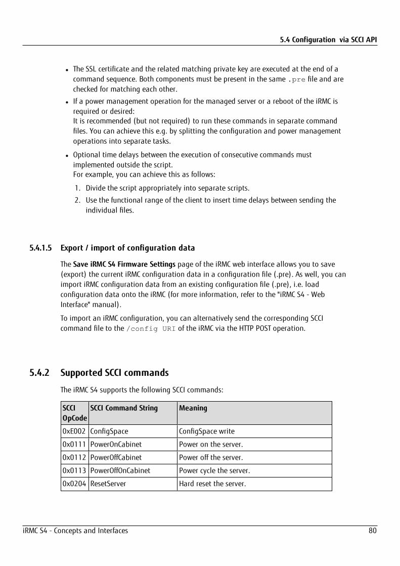
5.4 Configuration via SCCI API
l The SSL certificate and the related matching private key are executed at the end of acommand sequence. Both components must be present in the same .pre file and arechecked for matching each other.
l If a power management operation for the managed server or a reboot of the iRMC isrequired or desired:It is recommended (but not required) to run these commands in separate commandfiles. You can achieve this e.g. by splitting the configuration and power managementoperations into separate tasks.
l Optional time delays between the execution of consecutive commands mustimplemented outside the script.For example, you can achieve this as follows:
1. Divide the script appropriately into separate scripts.
2. Use the functional range of the client to insert time delays between sending theindividual files.
5.4.1.5 Export / import of configuration data
The Save iRMC S4 Firmware Settings page of the iRMC web interface allows you to save(export) the current iRMC configuration data in a configuration file (.pre). As well, you canimport iRMC configuration data from an existing configuration file (.pre), i.e. loadconfiguration data onto the iRMC (for more information, refer to the "iRMC S4 - WebInterface" manual).
To import an iRMC configuration, you can alternatively send the corresponding SCCIcommand file to the /config URI of the iRMC via the HTTP POST operation.
5.4.2 Supported SCCI commands
The iRMC S4 supports the following SCCI commands:
SCCIOpCode
SCCI Command String Meaning
0xE002 ConfigSpace ConfigSpace write
0x0111 PowerOnCabinet Power on the server.
0x0112 PowerOffCabinet Power off the server.
0x0113 PowerOffOnCabinet Power cycle the server.
0x0204 ResetServer Hard reset the server.
iRMC S4 - Concepts and Interfaces 80

5.4 Configuration via SCCI API
SCCIOpCode
SCCI Command String Meaning
0x020C RaiseNMI Pulse the NMI (Non Maskable Interrupt).
0x0205 RequestShutdownAndOff Graceful shutdown, requires running agent.
0x0206 RequestShutdownAndReset Graceful reboot, requires running agent.
0x0209 ShutdownRequestCancelled Cancel a shutdown request.
0x0203 ResetFirmware Perform a BMC reset.
0x0250 ConnectRemoteFdImage Connect or disconnect a floppy disk image on aremote image mount (NFS or CIFS share).
0x0251 ConnectRemoteCdImage Connect or disconnect a CD/DVD .iso image on aremote image mount (NFS or CIFS share).
0x0252 ConnectRemoteHdImage Connect or disconnect a hard disk image on aremote image mount (NFS or CIFS share).
5.4.3 Script Examples
5.4.3.1 cURL examples
The open source command-line tool cURL allows you to transfer data specified with URLsyntax. You can download the latest version of the source code as well as precompiledversions for different operating systems from http://curl.haxx.se/.
The following are some examples of how to use cURL to send a configuration file to theiRMC.
For details on the cURL command line options please refer to the cURLdocumentation.
l HTTP Access with Basic Authentication (default) and the default iRMC S4 adminaccount:curl --basic -u admin:admin --data @Config.pre
http://<iRMC IP address>/config
l HTTP Access with Digest Authentication and the default iRMC admin account:curl --digest -u admin:admin --data @Config.pre
http://<iRMC IP address>/config
l HTTPS Access with no certificate check (-k) and Digest authentication and the defaultiRMC admin account:curl --digest -k -u admin:admin --data @Config.prehttps://<iRMC IP address>/config
iRMC S4 - Concepts and Interfaces 81
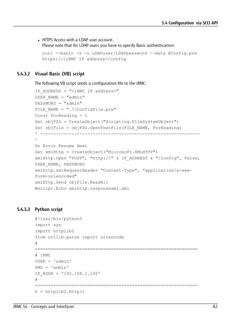
5.4 Configuration via SCCI API
l HTTPS Access with a LDAP user account.Please note that for LDAP users you have to specify Basic authentication:
curl --basic -k -u LDAPuser:LDAPpassword --data @Config.prehttps://<iRMC IP address>/config
5.4.3.2 Visual Basic (VB) script
The following VB script sends a configuration file to the iRMC:
IP_ADDRESS = "<iRMC IP address>"
USER_NAME = "admin"
PASSWORD = "admin"
FILE_NAME = ".\\ConfigFile.pre"
Const ForReading = 1
Set objFSO = CreateObject("Scripting.FileSystemObject")
Set objFile = objFSO.OpenTextFile(FILE_NAME, ForReading)
' --------------------------------------------------------------
On Error Resume Next
Set xmlHttp = CreateObject("Microsoft.XMLHTTP")
xmlHttp.Open "POST", "http://" & IP_ADDRESS & "/config", False,
USER_NAME, PASSWORD
xmlhttp.setRequestHeader "Content-Type", "application/x-www-form-urlencoded"
xmlHttp.Send objFile.ReadAll
Wscript.Echo xmlhttp.responsexml.xml
5.4.3.3 Python script
#!/usr/bin/python3
import sys
import httplib2
from urllib.parse import urlencode
#==============================================================
# iRMC
USER = 'admin'
PWD = 'admin'
IP_ADDR = '192.168.1.100'
#==============================================================
h = httplib2.Http()
iRMC S4 - Concepts and Interfaces 82
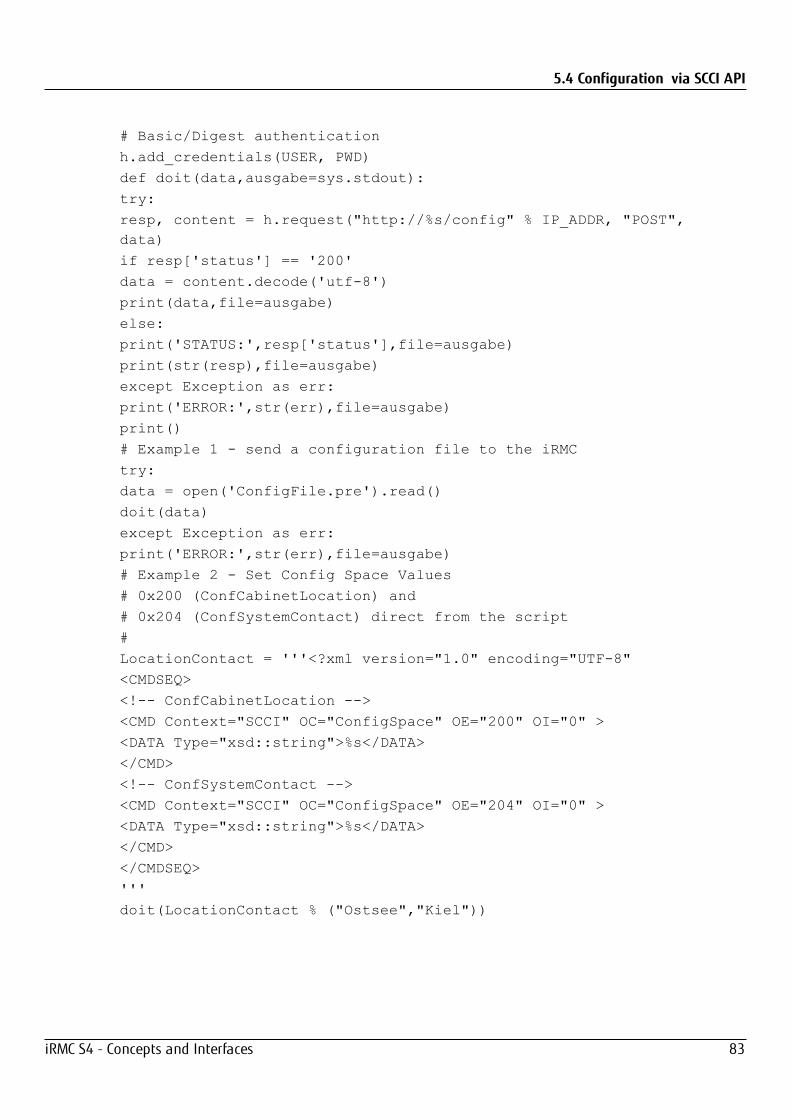
5.4 Configuration via SCCI API
# Basic/Digest authentication
h.add_credentials(USER, PWD)
def doit(data,ausgabe=sys.stdout):
try:
resp, content = h.request("http://%s/config" % IP_ADDR, "POST",data)
if resp['status'] == '200'
data = content.decode('utf-8')
print(data,file=ausgabe)
else:
print('STATUS:',resp['status'],file=ausgabe)
print(str(resp),file=ausgabe)
except Exception as err:
print('ERROR:',str(err),file=ausgabe)
print()
# Example 1 - send a configuration file to the iRMC
try:
data = open('ConfigFile.pre').read()
doit(data)
except Exception as err:
print('ERROR:',str(err),file=ausgabe)
# Example 2 - Set Config Space Values
# 0x200 (ConfCabinetLocation) and
# 0x204 (ConfSystemContact) direct from the script
#
LocationContact = '''<?xml version="1.0" encoding="UTF-8"
<CMDSEQ>
<!-- ConfCabinetLocation -->
<CMD Context="SCCI" OC="ConfigSpace" OE="200" OI="0" >
<DATA Type="xsd::string">%s</DATA>
</CMD>
<!-- ConfSystemContact -->
<CMD Context="SCCI" OC="ConfigSpace" OE="204" OI="0" >
<DATA Type="xsd::string">%s</DATA>
</CMD>
</CMDSEQ>
'''
doit(LocationContact % ("Ostsee","Kiel"))
iRMC S4 - Concepts and Interfaces 83
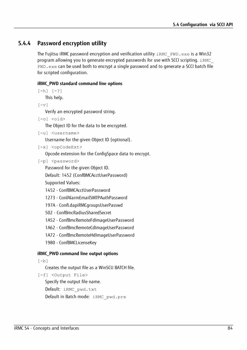
5.4 Configuration via SCCI API
5.4.4 Password encryption utility
The Fujitsu iRMC password encryption and verification utility iRMC_PWD.exe is a Win32program allowing you to generate encrypted passwords for use with SCCI scripting. iRMC_PWD.exe can be used both to encrypt a single password and to generate a SCCI batch filefor scripted configuration.
iRMC_PWD standard command line options[-h] [-?]
This help.
[-v]
Verify an encrypted password string.
[-o] <oid>
The Object ID for the data to be encrypted.
[-u] <username>
Username for the given Object ID (optional).
[-x] <opCodeExt>
Opcode extension for the ConfigSpace data to encrypt.
[-p] <password>
Password for the given Object ID.
Default: 1452 (ConfBMCAcctUserPassword)
Supported Values:
1452 - ConfBMCAcctUserPassword
1273 - ConfAlarmEmailSMTPAuthPassword
197A - ConfLdapiRMCgroupsUserPasswd
502 - ConfBmcRadiusSharedSecret
1A52 - ConfBmcRemoteFdImageUserPassword
1A62 - ConfBmcRemoteCdImageUserPassword
1A72 - ConfBmcRemoteHdImageUserPassword
1980 - ConfBMCLicenseKey
iRMC_PWD command line output options[-b]
Creates the output file as a WinSCU BATCH file.
[-f] <Output File>
Specify the output file name.
Default: iRMC_pwd.txt
Default in Batch mode: iRMC_pwd.pre
iRMC S4 - Concepts and Interfaces 84
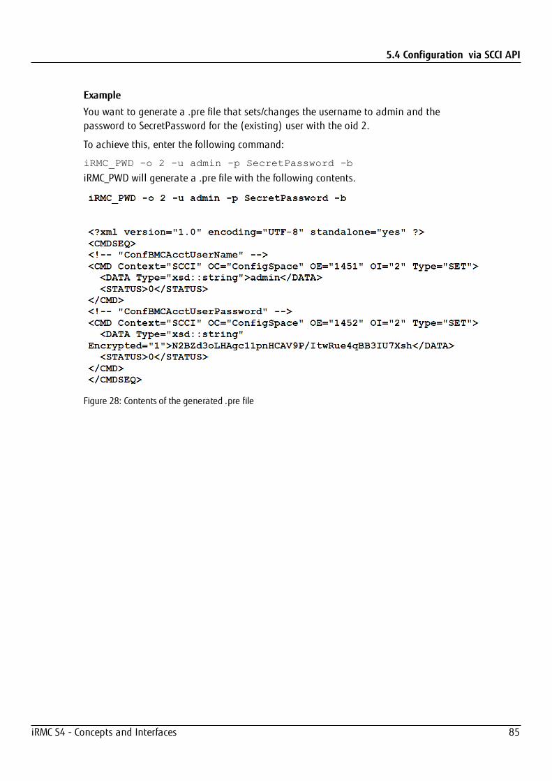
5.4 Configuration via SCCI API
Example
You want to generate a .pre file that sets/changes the username to admin and thepassword to SecretPassword for the (existing) user with the oid 2.
To achieve this, enter the following command:
iRMC_PWD -o 2 -u admin -p SecretPassword -b
iRMC_PWD will generate a .pre file with the following contents.
Figure 28: Contents of the generated .pre file
iRMC S4 - Concepts and Interfaces 85

6 Monitoring the iRMC
6.1 Monitoring with SNMPSNMP (Simple Network Management Protocol) is an application-layer protocol thatprovides a message format for communication between SNMP managers and agents.SNMP provides a standardized framework and a common language used for themonitoring and management of devices in a network.
The SNMP framework has three parts:
l SNMP manager
l SNMP agent
l MIB
The SNMP manager is the system used to control and monitor the activities of networkhosts using SNMP. The most common managing system is called a Network ManagementSystem (NMS). The term NMS can be applied to either a dedicated device used for networkmanagement, or the applications used on such a device. A variety of networkmanagement applications are available for use with SNMP. These features range fromsimple command-line applications to feature-rich graphical user interfaces.
The SNMP agent is the software component within the managed device that maintains thedata for the device and reports these data, as needed, to managing systems. Agent andMIB reside on the routing device (router, access server, or switch). To enable the SNMPagent, you must define a relationship between the manager and the agent.
The Management Information Base (MIB) is a virtual information storage area for networkmanagement information, which consists of collections of managed objects. Within theMIB there are collections of related objects, defined in MIB modules. MIB modules arewritten in the SNMP MIB module language, as defined in STD 58, RFC 2578, RFC 2579, andRFC 2580.
The SNMP agent contains MIB variables whose values the SNMP manager can request orchange with Get or Set operations. A manager can get a value from an agent or store avalue into that agent. The agent gathers data from the MIB, the repository for informationabout device parameters and network data. The agent can also respond to managerrequests to Get or Set data.
A key feature of SNMP is the ability to generate notifications from an SNMP agent. Thesenotifications do not require that requests be sent from the SNMP manager. Asynchronousnotifications can be generated as traps or inform requests. Traps are messages alertingthe SNMP manager to a condition on the network. Inform requests (informs) are traps that
iRMC S4 - Concepts and Interfaces 86

6.1 Monitoring with SNMP
include a request for confirmation of receipt from the SNMP manager. Notifications canindicate improper user authentication, restarts, the closing of a connection, loss ofconnection to a neighbor router, or other significant events.
Traps are less reliable than informs because the receiver does not send anyacknowledgment when it receives a trap. The sender cannot determine if the trap wasreceived. An SNMP manager that receives an inform request acknowledges the messagewith an SNMP response protocol data unit (PDU). If the manager does not receive aninform request, it does not send a response. If the sender never receives a response, theinform request can be sent again. Thus, informs are more likely to reach their intendeddestination.
However, traps are often preferred because informs consume more resources in the routerand in the network. Unlike a trap, which is discarded as soon as it is sent, an informrequest must be held in memory until a response is received or the request times out. Also,traps are sent only once, while an inform may be retried several times. The retries increasetraffic and contribute to a higher overhead on the network. Thus, traps and informrequests provide a trade-off between reliability and resources. If it is important that theSNMP manager receives every notification, use inform requests. However, if you areconcerned about traffic on your network or memory in the router and you need not receiveevery notification, use traps.
The iRMC supports the following versions of SNMP:
l SNMPv1 is a full Internet standard, defined in RFC 1157. (RFC 1157 replaces the earlierversions that were published as RFC 1067 and RFC 1098.) Security is based oncommunity strings.
l SNMPv2c is an experimental Internet protocol defined in RFC 1901, RFC 1905, and RFC1906. SNMPv2c is an update of the protocol operations and data types of SNMPv2p(SNMPv2 Classic), and uses the community-based security model of SNMPv1.
l SNMPv3 is an interoperable standards-based protocol defined in RFCs 2273 to 2275.SNMPv3 provides secure access to devices by a combination of authenticating andencrypting packets over the network.The security features provided in SNMPv3 are as follows:
l Message integrity: ensuring that a packet has not been tampered with in transit.
l Authentication: determining that the message is from a valid source.
l Encryption: scrambling the contents of a packet prevent it from being learned byan unauthorized source.
By default, the SNMP service on the iRMC S4 is disabled.
The SNMP service on the iRMC S4 supports GET requests on the following SNMP MIBs:
l SNMP STATUS.MIB
l SNMP OS.MIB
l SNMP SC2.MIB
l SNMP MIB-2.MIB
iRMC S4 - Concepts and Interfaces 87
6.2 iRMC system report
These MIBs are provided on the FUJITSU Software ServerView Suite DVD. Additionally, youcan download them from the ServerView Suite page.
When the SNMP service is enabled, information provided by these MIBs can be used by anysystem running an SNMP manager.
6.2 iRMC system reportTypically, the information is collected by the ServerView Agents running on the hostoperating system and includes various types of hardware and software information. Thecollected information includes, among others, iRMC information (sensor, IDPROM/FRU,eventlog) as well as software and drivers installed on the host operating, runningprocesses etc.
Even in cases where ServerView Agents are not running, a subset of this information,comprising mainly service incidents, can be made available directly out-of-band from theiRMC.
This section gives some examples on scripted download and automatic evaluation of theiRMC report and shows system report items provided by the iRMC.
6.2.1 cURL script for download
cURL is an open source command line tool for transferring data specified with URL syntax.The latest version of the source code as well as precompiled versions for differentoperating systems can be downloaded from http://curl.haxx.se/.
The following are some examples of how to retrieve the System Report file with cURL fromthe iRMC, for details of the cURL command line options please refer to the cURLdocumentation. As default cURL sends the retrieved data to standard output, you canredirect or pipe it into additional processing or save the retrieved data with the –o<outputfilename>.
l HTTP access with Digest authentication, the default iRMC admin account and saving (-o) to ‘report.xml’:curl --digest –o report.xml -u admin:adminhttp://192.168.1.100/report.xml
l HTTPS Access with no certificate check (-k) and Digest authentication and the defaultiRMC admin account:curl --digest -k -u admin:adminhttps://192.168.1.100/report.xml
l HTTPS Access with a LDAP user account:Please note that, for LDAP users, you have to specify basic authentication since theauthentication parameters need to be passed to the LDAP server for verification:
iRMC S4 - Concepts and Interfaces 88
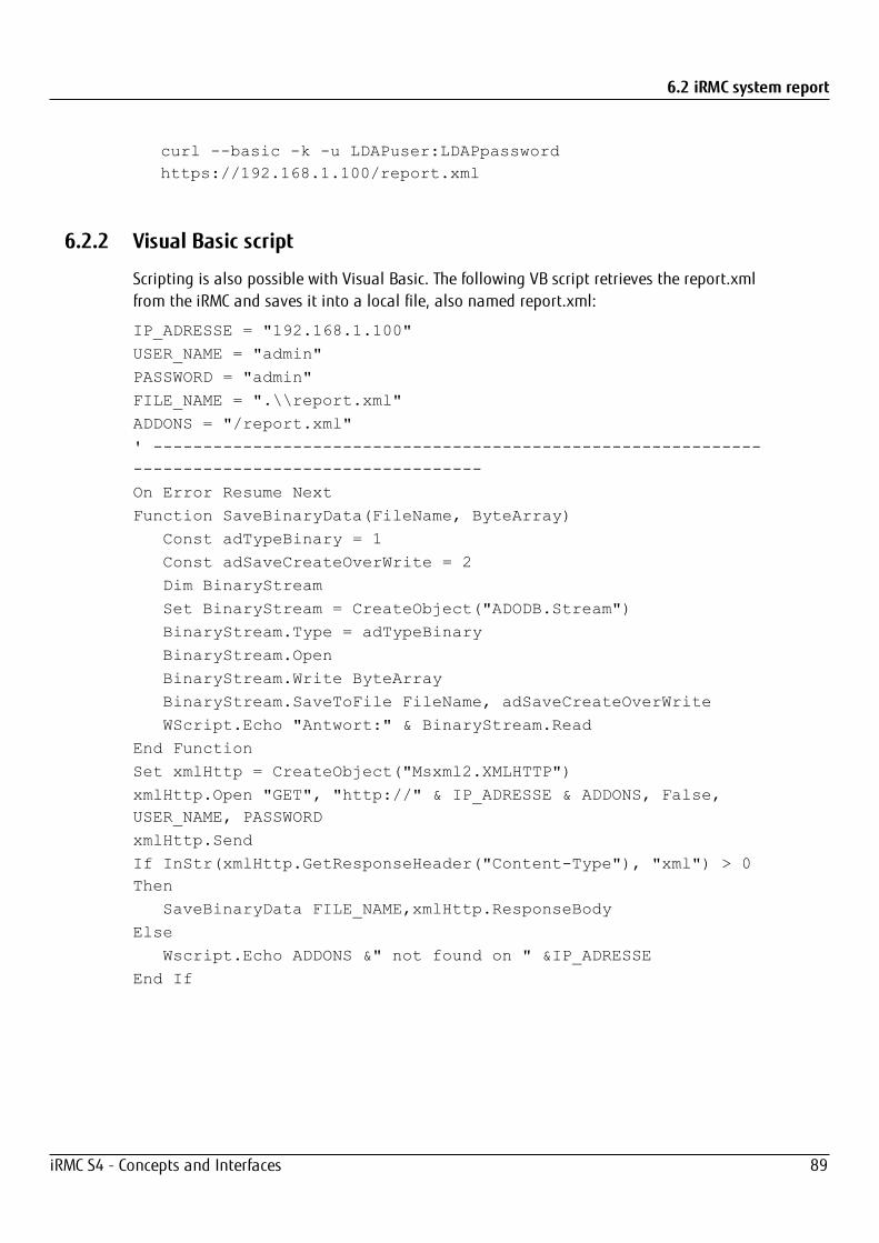
6.2 iRMC system report
curl --basic -k -u LDAPuser:LDAPpasswordhttps://192.168.1.100/report.xml
6.2.2 Visual Basic script
Scripting is also possible with Visual Basic. The following VB script retrieves the report.xmlfrom the iRMC and saves it into a local file, also named report.xml:
IP_ADRESSE = "192.168.1.100"
USER_NAME = "admin"
PASSWORD = "admin"
FILE_NAME = ".\\report.xml"
ADDONS = "/report.xml"
' ------------------------------------------------------------------------------------------------
On Error Resume Next
Function SaveBinaryData(FileName, ByteArray)
Const adTypeBinary = 1
Const adSaveCreateOverWrite = 2
Dim BinaryStream
Set BinaryStream = CreateObject("ADODB.Stream")
BinaryStream.Type = adTypeBinary
BinaryStream.Open
BinaryStream.Write ByteArray
BinaryStream.SaveToFile FileName, adSaveCreateOverWrite
WScript.Echo "Antwort:" & BinaryStream.Read
End Function
Set xmlHttp = CreateObject("Msxml2.XMLHTTP")
xmlHttp.Open "GET", "http://" & IP_ADRESSE & ADDONS, False,USER_NAME, PASSWORD
xmlHttp.Send
If InStr(xmlHttp.GetResponseHeader("Content-Type"), "xml") > 0Then
SaveBinaryData FILE_NAME,xmlHttp.ResponseBody
Else
Wscript.Echo ADDONS &" not found on " &IP_ADRESSE
End If
iRMC S4 - Concepts and Interfaces 89
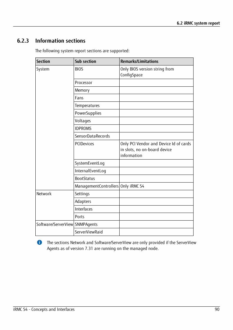
6.2 iRMC system report
6.2.3 Information sections
The following system report sections are supported:
Section Sub section Remarks/Limitations
System BIOS Only BIOS version string fromConfigSpace
Processor
Memory
Fans
Temperatures
PowerSupplies
Voltages
IDPROMS
SensorDataRecords
PCIDevices Only PCI Vendor and Device Id of cardsin slots, no on-board deviceinformation
SystemEventLog
InternalEventLog
BootStatus
ManagementControllers Only iRMC S4
Network Settings
Adapters
Interfaces
Ports
Software/ServerView SNMPAgents
ServerViewRaid
The sections Network and Software/ServerView are only provided if the ServerViewAgents as of version 7.31 are running on the managed node.
iRMC S4 - Concepts and Interfaces 90
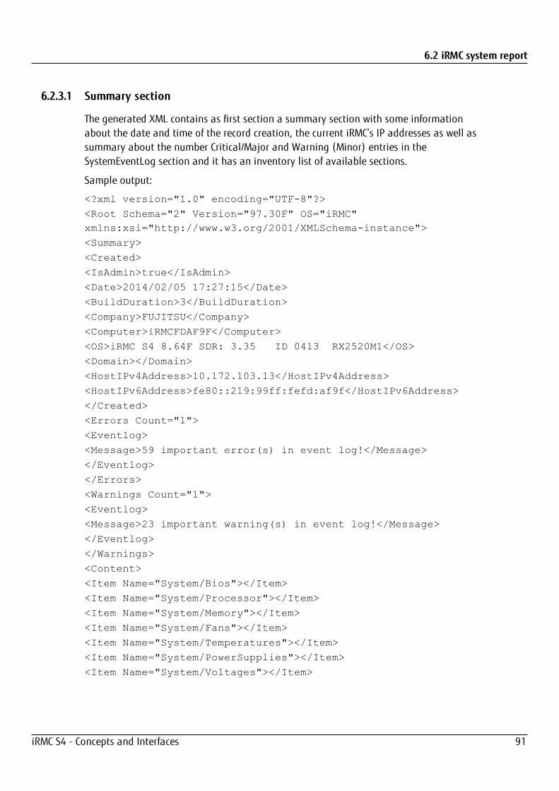
6.2 iRMC system report
6.2.3.1 Summary section
The generated XML contains as first section a summary section with some informationabout the date and time of the record creation, the current iRMC’s IP addresses as well assummary about the number Critical/Major and Warning (Minor) entries in theSystemEventLog section and it has an inventory list of available sections.
Sample output:
<?xml version="1.0" encoding="UTF-8"?>
<Root Schema="2" Version="97.30F" OS="iRMC"xmlns:xsi="http://www.w3.org/2001/XMLSchema-instance">
<Summary>
<Created>
<IsAdmin>true</IsAdmin>
<Date>2014/02/05 17:27:15</Date>
<BuildDuration>3</BuildDuration>
<Company>FUJITSU</Company>
<Computer>iRMCFDAF9F</Computer>
<OS>iRMC S4 8.64F SDR: 3.35 ID 0413 RX2520M1</OS>
<Domain></Domain>
<HostIPv4Address>10.172.103.13</HostIPv4Address>
<HostIPv6Address>fe80::219:99ff:fefd:af9f</HostIPv6Address>
</Created>
<Errors Count="1">
<Eventlog>
<Message>59 important error(s) in event log!</Message>
</Eventlog>
</Errors>
<Warnings Count="1">
<Eventlog>
<Message>23 important warning(s) in event log!</Message>
</Eventlog>
</Warnings>
<Content>
<Item Name="System/Bios"></Item>
<Item Name="System/Processor"></Item>
<Item Name="System/Memory"></Item>
<Item Name="System/Fans"></Item>
<Item Name="System/Temperatures"></Item>
<Item Name="System/PowerSupplies"></Item>
<Item Name="System/Voltages"></Item>
iRMC S4 - Concepts and Interfaces 91

6.2 iRMC system report
<Item Name="System/IDPROMS"></Item>
<Item Name="System/SensorDataRecords"></Item>
<Item Name="System/PCIDevices"></Item>
<Item Name="System/SystemEventlog"></Item>
<Item Name="System/InternalEventlog"></Item>
<Item Name="System/BootStatus"></Item>
<Item Name="System/ManagementControllers"></Item>
<Item Name="Network/Settings"></Item>
<Item Name="Network/Adapters"></Item>
<Item Name="Network/Interfaces"></Item>
<Item Name="Network/Ports"></Item>
<Item Name="Software/ServerView/SNMPAgents"></Item>
<Item Name="Software/ServerView/ServerViewRaid"></Item>
</Content>
</Summary>
<System>
6.2.3.2 BIOS section
Since the iRMC has no access to the SMBIOS structures of the server, only a very limitedsubset of information is provided.
Example:
<Bios Schema="1">
<SMBIOS Version="Unknown">
<Type0 Name="BIOS Information" Type="0">
<BiosVersion>V4.6.5.4 R1.0.0 for D3239-A1x</BiosVersion>
</Type0>
</SMBIOS>
</Bios>
6.2.3.3 Processor section
The information generated is based on the F113 and F115 OEM IPMI cmd and is compliantwith the CDiagReport.h.
<Processor Schema="1">
<CPU Boot="true">
<SocketDesignation>CPU</SocketDesignation>
<Manufacturer>Intel</Manufacturer>
<Model>
<Version>Intel(R) Xeon(R) CPU E3-1270 v3 @ 3.50GHz</Version>
iRMC S4 - Concepts and Interfaces 92

6.2 iRMC system report
<BrandName>Intel(R) Xeon(R) CPU E3-1270 v3 @3.50GHz</BrandName>
</Model>
<Speed>3500</Speed>
<Status Description="ok">1</Status>
<CoreNumber>4</CoreNumber>
<LogicalCpuNumber>8</LogicalCpuNumber>
<Level1CacheSize Unit="KByte">256</Level1CacheSize>
<Level2CacheSize Unit="KByte">1024</Level2CacheSize>
<Level3CacheSize Unit="KByte">8192</Level3CacheSize>
</CPU>
</Processor>
6.2.3.4 Memory section
The information generated is retrieved by decoding the memory SPD data as well asevaluating the memory status and configuration sensors and is compliant with theCDiagReport.h implementation.
<Memory Schema="2">
<Modules Count="4">
<Module Name="DIMM-2A" CSS="true">
<Status Description="empty">0</Status>
</Module>
<Module Name="DIMM-1A" CSS="true">
<Status Description="ok">1</Status>
<Approved>false</Approved>
<Size Unit="GByte">2</Size>
<Type>DDR3</Type>
<BusFrequency Unit="MHz">1600</BusFrequency>
<SPD Size="256" Revision="1.2" Checksum="true">
<Checksum>
<Data>33879</Data>
<Calculated>33879</Calculated>
</Checksum>
<ModuleManufacturer>SK Hynix</ModuleManufacturer>
<ModuleManufacturingDate>2013,4</ModuleManufacturing Date>
<ModulePartNumber>HMT325U7EFR8A-PB </ModulePartNumber>
<ModuleRevisionCode>12372</ModuleRevisionCode>
<ModuleSerialNumberAsString="4C633E39">1281572409</ModuleSerialNumber>
<ModuleType>UDIMM</ModuleType>
<DeviceType>DDR3_SDRAM</DeviceType>
iRMC S4 - Concepts and Interfaces 93
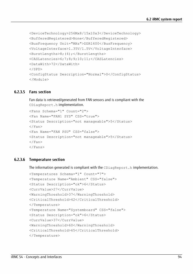
6.2 iRMC system report
<DeviceTechnology>256Mx8/15x10x3</DeviceTechnology>
<BufferedRegistered>None</BufferedRegistered>
<BusFrequency Unit="MHz">DDR1600</BusFrequency>
<VoltageInterface>1.35V/1.5V</VoltageInterface>
<BurstLengths>8;(4);</BurstLengths>
<CASLatencies>6;7;8;9;10;11;</CASLatencies>
<DataWith>72</DataWith>
</SPD>
<ConfigStatus Description="Normal">0</ConfigStatus>
</Module>
6.2.3.5 Fans section
Fan data is retrieved/generated from FAN sensors and is compliant with theCDiagReport.h implementation.
<Fans Schema="1" Count="2">
<Fan Name="FAN1 SYS" CSS="true">
<Status Description="not manageable">5</Status>
</Fan>
<Fan Name="FAN PSU" CSS="false">
<Status Description="not manageable">5</Status>
</Fan>
</Fans>
6.2.3.6 Temperature section
The information generated is compliant with the CDiagReport.h implementation.
<Temperatures Schema="1" Count="7">
<Temperature Name="Ambient" CSS="false">
<Status Description="ok">6</Status>
<CurrValue>27</CurrValue>
<WarningThreshold>37</WarningThreshold>
<CriticalThreshold>42</CriticalThreshold>
</Temperature>
<Temperature Name="Systemboard" CSS="false">
<Status Description="ok">6</Status>
<CurrValue>37</CurrValue>
<WarningThreshold>60</WarningThreshold>
<CriticalThreshold>65</CriticalThreshold>
</Temperature>
iRMC S4 - Concepts and Interfaces 94
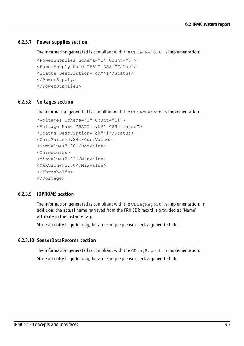
6.2 iRMC system report
6.2.3.7 Power supplies section
The information generated is compliant with the CDiagReport.h implementation.
<PowerSupplies Schema="1" Count="1">
<PowerSupply Name="PSU" CSS="false">
<Status Description="ok">1</Status>
</PowerSupply>
</PowerSupplies>
6.2.3.8 Voltages section
The information generated is compliant with the CDiagReport.h implementation.
<Voltages Schema="1" Count="11">
<Voltage Name="BATT 3.0V" CSS="false">
<Status Description="ok">1</Status>
<CurrValue>3.24</CurrValue>
<NomValue>3.00</NomValue>
<Thresholds>
<MinValue>2.02</MinValue>
<MaxValue>3.50</MaxValue>
</Thresholds>
</Voltage>
6.2.3.9 IDPROMS section
The information generated is compliant with the CDiagReport.h implementation. Inaddition, the actual name retrieved from the FRU SDR record is provided as “Name”attribute in the instance tag.
Since an entry is quite long, for an example please check a generated file.
6.2.3.10 SensorDataRecords section
The information generated is compliant with the CDiagReport.h implementation.
Since an entry is quite long, for an example please check a generated file.
iRMC S4 - Concepts and Interfaces 95

6.2 iRMC system report
6.2.3.11 PCIDevices section
The iRMC does not have any direct access to PCI data and therefore can only report alimited subset on information. This information is based on what the server BIOS has sentwith the F119 OEM IPMI cmd and which can be retrieved with the F11A OEM IPMI cmd.
<PCIDevices Schema="1">
<Device>
<ConfigSpace>
<VendorId>1000</VendorId>
<DeviceId>005B</DeviceId>
<SubVendorId>11D3</SubVendorId>
<SubDeviceId>1734</SubDeviceId>
<BaseClass>Mass storage controller</BaseClass>
<SubClass>RAID controller</SubClass>
</ConfigSpace>
<Slot>4</Slot>
</Device>
</PCIDevices>
6.2.3.12 SystemEventLog section
The information generated is compliant with the CDiagReport.h implementation.
<SystemEventlog Schema="1">
<Entry>
<Date>2014/02/05 16:48:13</Date>
<Severity>MINOR</Severity>
<ErrorCode>19000B</ErrorCode>
<Message>'DIMM-1B': Non Fujitsu Memory Module detected -Warranty restricted!</Message>
<Data Size="14">
<HexDump Lines="1" BytesPerLine="14">
<Line Offset="0">
<Hex>02 4D 6B F2 52 20 00 04 E1 FE 6F A0 00 03</Hex>
</Line>
</HexDump>
</Data>
</Entry>
iRMC S4 - Concepts and Interfaces 96
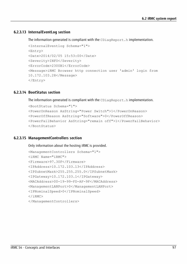
6.2 iRMC system report
6.2.3.13 InternalEventLog section
The information generated is compliant with the CDiagReport.h implementation.
<InternalEventlog Schema="1">
<Entry>
<Date>2014/02/05 15:53:00</Date>
<Severity>INFO</Severity>
<ErrorCode>2300B1</ErrorCode>
<Message>iRMC Browser http connection user 'admin' login from10.172.103.28</Message>
</Entry>
6.2.3.14 BootStatus section
The information generated is compliant with the CDiagReport.h implementation.
<BootStatus Schema="1">
<PowerOnReason AsString="Power Switch">1</PowerOnReason>
<PowerOffReason AsString="Software">0</PowerOffReason>
<PowerFailBehavior AsString="remain off">1</PowerFailBehavior>
</BootStatus>
6.2.3.15 ManagementControllers section
Only information about the hosting iRMC is provided.
<ManagementControllers Schema="1">
<iRMC Name="iRMC">
<Firmware>97.30F</Firmware>
<IPAddress>10.172.103.13</IPAddress>
<IPSubnetMask>255.255.255.0</IPSubnetMask>
<IPGateway>10.172.103.1</IPGateway>
<MACAddress>00-19-99-FD-AF-9F</MACAddress>
<ManagementLANPort>0</ManagementLANPort>
<IPNominalSpeed>0</IPNominalSpeed>
</iRMC>
</ManagementControllers>
iRMC S4 - Concepts and Interfaces 97
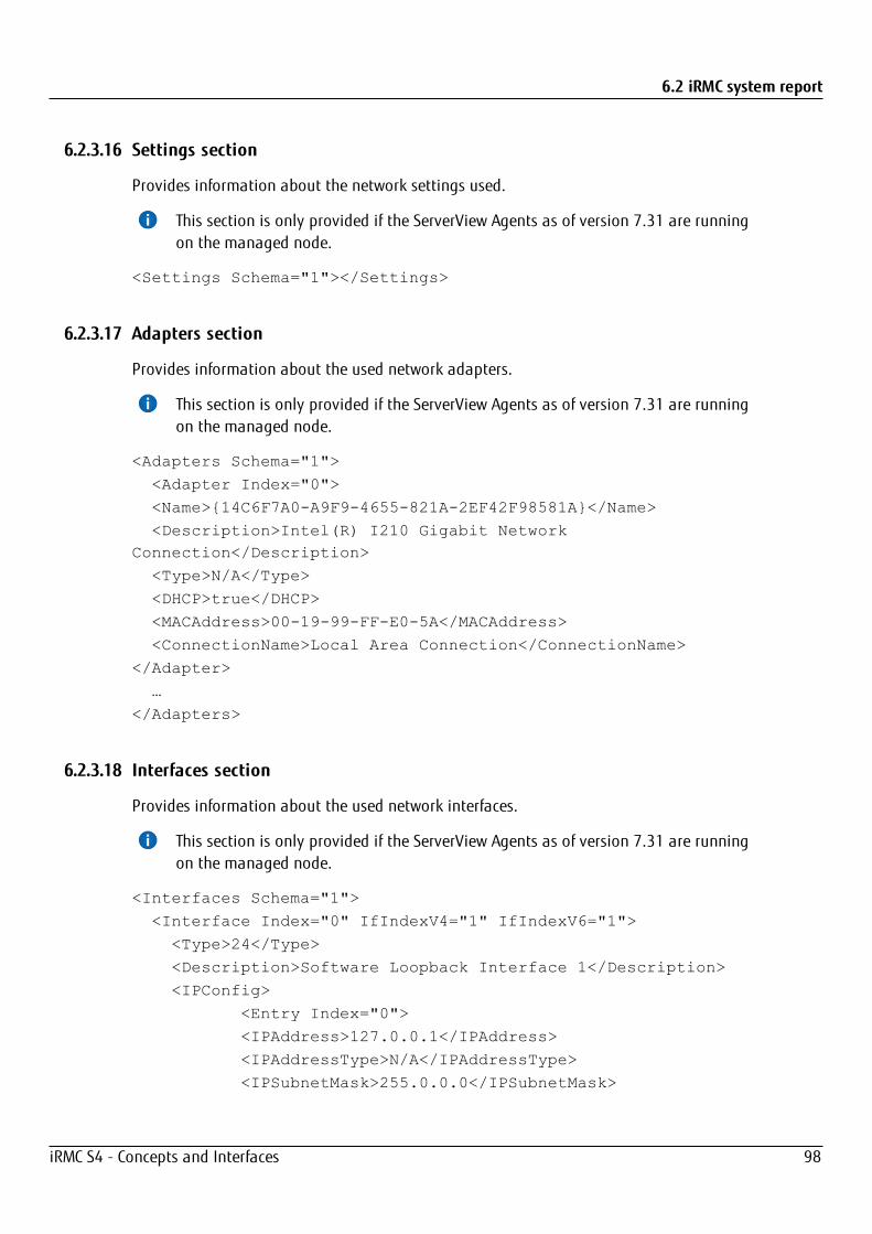
6.2 iRMC system report
6.2.3.16 Settings section
Provides information about the network settings used.
This section is only provided if the ServerView Agents as of version 7.31 are runningon the managed node.
<Settings Schema="1"></Settings>
6.2.3.17 Adapters section
Provides information about the used network adapters.
This section is only provided if the ServerView Agents as of version 7.31 are runningon the managed node.
<Adapters Schema="1">
<Adapter Index="0">
<Name>{14C6F7A0-A9F9-4655-821A-2EF42F98581A}</Name>
<Description>Intel(R) I210 Gigabit NetworkConnection</Description>
<Type>N/A</Type>
<DHCP>true</DHCP>
<MACAddress>00-19-99-FF-E0-5A</MACAddress>
<ConnectionName>Local Area Connection</ConnectionName>
</Adapter>
…
</Adapters>
6.2.3.18 Interfaces section
Provides information about the used network interfaces.
This section is only provided if the ServerView Agents as of version 7.31 are runningon the managed node.
<Interfaces Schema="1">
<Interface Index="0" IfIndexV4="1" IfIndexV6="1">
<Type>24</Type>
<Description>Software Loopback Interface 1</Description>
<IPConfig>
<Entry Index="0">
<IPAddress>127.0.0.1</IPAddress>
<IPAddressType>N/A</IPAddressType>
<IPSubnetMask>255.0.0.0</IPSubnetMask>
iRMC S4 - Concepts and Interfaces 98
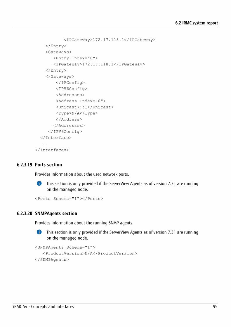
6.2 iRMC system report
<IPGateway>172.17.118.1</IPGateway>
</Entry>
<Gateways>
<Entry Index="0">
<IPGateway>172.17.118.1</IPGateway>
</Entry>
</Gateways>
</IPConfig>
<IPV6Config>
<Addresses>
<Address Index="0">
<Unicast>::1</Unicast>
<Type>N/A</Type>
</Address>
</Addresses>
</IPV6Config>
</Interface>
…
</Interfaces>
6.2.3.19 Ports section
Provides information about the used network ports.
This section is only provided if the ServerView Agents as of version 7.31 are runningon the managed node.
<Ports Schema="1"></Ports>
6.2.3.20 SNMPAgents section
Provides information about the running SNMP agents.
This section is only provided if the ServerView Agents as of version 7.31 are runningon the managed node.
<SNMPAgents Schema="1">
<ProductVersion>N/A</ProductVersion>
</SNMPAgents>
iRMC S4 - Concepts and Interfaces 99
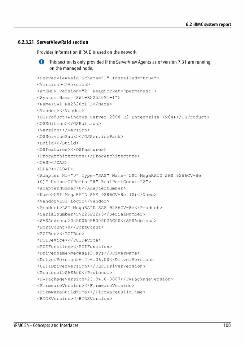
6.2 iRMC system report
6.2.3.21 ServerViewRaid section
Provides information if RAID is used on the network.
This section is only provided if the ServerView Agents as of version 7.31 are runningon the managed node.
<ServerViewRaid Schema="1" Installed="true">
<Version></Version>
<amEMSV Version="2" ReadSocket="permanent">
<System Name="SW1-RX2520M1-1">
<Name>SW1-RX2520M1-1</Name>
<Vendor></Vendor>
<OSProduct>Windows Server 2008 R2 Enterprise (x64)</OSProduct>
<OSEdition></OSEdition>
<Version></Version>
<OSServicePack></OSServicePack>
<Build></Build>
<OSFeatures></OSFeatures>
<ProcArchitecture></ProcArchitecture>
<CAS></CAS>
<LDAP></LDAP>
<Adapter Nr="0" Type="SAS" Name="LSI MegaRAID SAS 9286CV-8e(0)" NumberOfPorts="8" RealPortCount="2">
<AdapterNumber>0</AdapterNumber>
<Name>LSI MegaRAID SAS 9286CV-8e (0)</Name>
<Vendor>LSI Logic</Vendor>
<Product>LSI MegaRAID SAS 9286CV-8e</Product>
<SerialNumber>SV225P2245</SerialNumber>
<SASAddress>0x500605B00502AC00</SASAddress>
<PortCount>8</PortCount>
<PCIBus></PCIBus>
<PCIDevice></PCIDevice>
<PCIFunction></PCIFunction>
<DriverName>megasas2.sys</DriverName>
<DriverVersion>6.706.06.00</DriverVersion>
<UEFIDriverVersion></UEFIDriverVersion>
<Protocol>SAS600</Protocol>
<FWPackageVersion>23.34.0-0007</FWPackageVersion>
<FirmwareVersion></FirmwareVersion>
<FirmwareBuildTime></FirmwareBuildTime>
<BIOSVersion></BIOSVersion>
iRMC S4 - Concepts and Interfaces 100
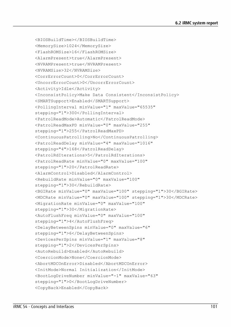
6.2 iRMC system report
<BIOSBuildTime></BIOSBuildTime>
<MemorySize>1024</MemorySize>
<FlashROMSize>16</FlashROMSize>
<AlarmPresent>true</AlarmPresent>
<NVRAMPresent>true</NVRAMPresent>
<NVRAMSize>32</NVRAMSize>
<CorrErrorCount>0</CorrErrorCount>
<UncorrErrorCount>0</UncorrErrorCount>
<Activity>Idle</Activity>
<InconsistPolicy>Make Data Consistent</InconsistPolicy>
<SMARTSupport>Enabled</SMARTSupport>
<PollingInterval minValue="1" maxValue="65535"stepping="1">300</PollingInterval>
<PatrolReadMode>Automatic</PatrolReadMode>
<PatrolReadMaxPD minValue="0" maxValue="255"stepping="1">255</PatrolReadMaxPD>
<ContinuousPatrolling>No</ContinuousPatrolling>
<PatrolReadDelay minValue="4" maxValue="1016"stepping="4">168</PatrolReadDelay>
<PatrolRdIterations>5</PatrolRdIterations>
<PatrolReadRate minValue="0" maxValue="100"stepping="1">20</PatrolReadRate>
<AlarmControl>Disabled</AlarmControl>
<RebuildRate minValue="0" maxValue="100"stepping="1">30</RebuildRate>
<BGIRate minValue="0" maxValue="100" stepping="1">30</BGIRate>
<MDCRate minValue="0" maxValue="100" stepping="1">30</MDCRate>
<MigrationRate minValue="0" maxValue="100"stepping="1">30</MigrationRate>
<AutoFlushFreq minValue="0" maxValue="100"stepping="1">4</AutoFlushFreq>
<DelayBetweenSpins minValue="0" maxValue="6"stepping="1">6</DelayBetweenSpins>
<DevicesPerSpins minValue="1" maxValue="8"stepping="1">2</DevicesPerSpins>
<AutoRebuild>Enabled</AutoRebuild>
<CoercionMode>None</CoercionMode>
<AbortMDCOnError>Disabled</AbortMDCOnError>
<InitMode>Normal Initialization</InitMode>
<BootLogDriveNumber minValue="-1" maxValue="63"stepping="1">0</BootLogDriveNumber>
<CopyBack>Enabled</CopyBack>
iRMC S4 - Concepts and Interfaces 101
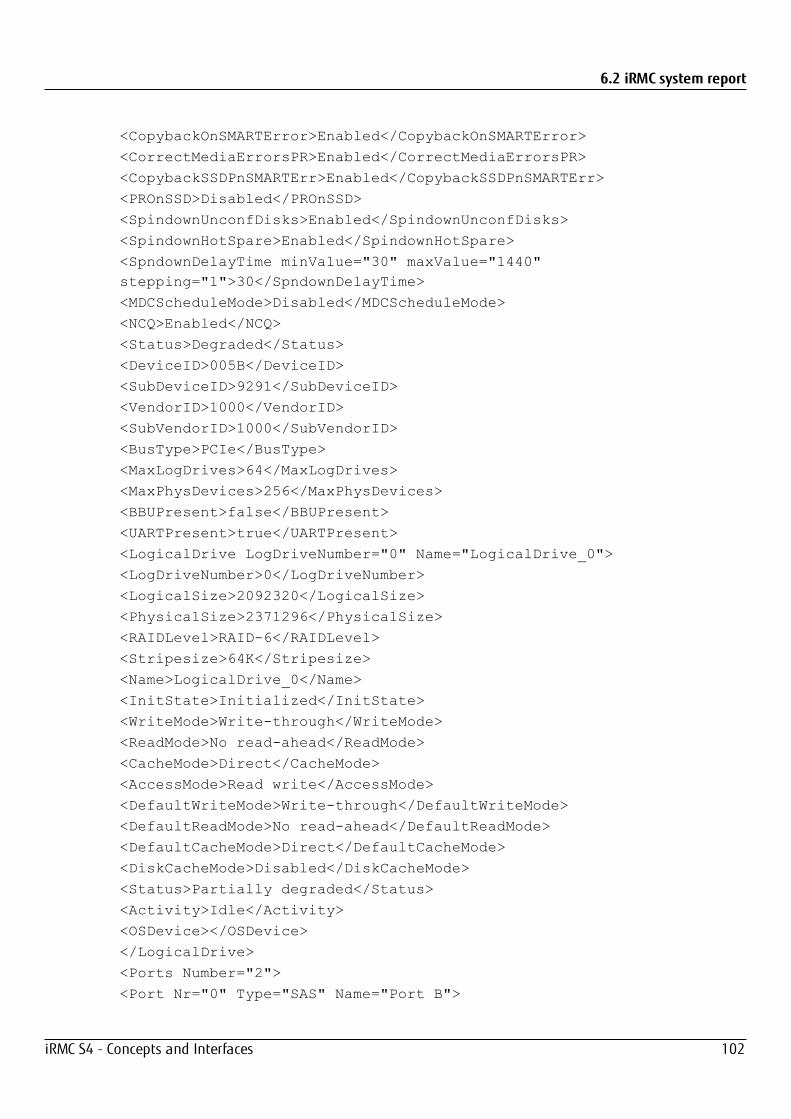
6.2 iRMC system report
<CopybackOnSMARTError>Enabled</CopybackOnSMARTError>
<CorrectMediaErrorsPR>Enabled</CorrectMediaErrorsPR>
<CopybackSSDPnSMARTErr>Enabled</CopybackSSDPnSMARTErr>
<PROnSSD>Disabled</PROnSSD>
<SpindownUnconfDisks>Enabled</SpindownUnconfDisks>
<SpindownHotSpare>Enabled</SpindownHotSpare>
<SpndownDelayTime minValue="30" maxValue="1440"stepping="1">30</SpndownDelayTime>
<MDCScheduleMode>Disabled</MDCScheduleMode>
<NCQ>Enabled</NCQ>
<Status>Degraded</Status>
<DeviceID>005B</DeviceID>
<SubDeviceID>9291</SubDeviceID>
<VendorID>1000</VendorID>
<SubVendorID>1000</SubVendorID>
<BusType>PCIe</BusType>
<MaxLogDrives>64</MaxLogDrives>
<MaxPhysDevices>256</MaxPhysDevices>
<BBUPresent>false</BBUPresent>
<UARTPresent>true</UARTPresent>
<LogicalDrive LogDriveNumber="0" Name="LogicalDrive_0">
<LogDriveNumber>0</LogDriveNumber>
<LogicalSize>2092320</LogicalSize>
<PhysicalSize>2371296</PhysicalSize>
<RAIDLevel>RAID-6</RAIDLevel>
<Stripesize>64K</Stripesize>
<Name>LogicalDrive_0</Name>
<InitState>Initialized</InitState>
<WriteMode>Write-through</WriteMode>
<ReadMode>No read-ahead</ReadMode>
<CacheMode>Direct</CacheMode>
<AccessMode>Read write</AccessMode>
<DefaultWriteMode>Write-through</DefaultWriteMode>
<DefaultReadMode>No read-ahead</DefaultReadMode>
<DefaultCacheMode>Direct</DefaultCacheMode>
<DiskCacheMode>Disabled</DiskCacheMode>
<Status>Partially degraded</Status>
<Activity>Idle</Activity>
<OSDevice></OSDevice>
</LogicalDrive>
<Ports Number="2">
<Port Nr="0" Type="SAS" Name="Port B">
iRMC S4 - Concepts and Interfaces 102

6.2 iRMC system report
<Name>Port B</Name>
<Enclosure Name="FUJITSU ETERNUS JX40 (1)">
<EnclosureNumber>1</EnclosureNumber>
<Vendor>FUJITSU</Vendor>
<Product>ETERNUS JX40</Product>
<HardwareVersion>0206</HardwareVersion>
<Name>FUJITSU ETERNUS JX40 (1)</Name>
<Status>OK</Status>
<SASAddress>0x500000E0D38027FE</SASAddress>
<Processor Name="FUJITSU JX40 (1:1)">
<PortNumber>0</PortNumber>
<DeviceNumber>60</DeviceNumber>
<EnclosureNumber>1</EnclosureNumber>
<Name>FUJITSU JX40 (1:1)</Name>
<Type>SES</Type>
<Vendor>FUJITSU</Vendor>
<Product>JX40</Product>
<SerialNumber>WK12090174</SerialNumber>
<PartNumber>CA07217-C871</PartNumber>
<HardwareVersion>AA </HardwareVersion>
<FirmwareVersion>V02L06</FirmwareVersion>
<Status>OK</Status>
<Fan Name="FAN0 PSU0 (0)">
<Name>FAN0 PSU0 (0)</Name>
<Location>PSU0</Location>
<FanSpeed>Low</FanSpeed>
<Status>OK</Status>
</Fan>
…
<PowerSupply Name="PSU0 (0)">
<PartNumber>CA05954-1100</PartNumber>
<SerialNumber>FA09350317</SerialNumber>
<HardwareVersion>08C 0</HardwareVersion>
<Status>OK</Status>
<Name>PSU0 (0)</Name>
</PowerSupply>
…
<TemperatureSensor Name="Sensor (0)">
<Name>Sensor (0)</Name>
<Location>LED panel</Location>
<WarningTemperatureH>45</WarningTemperatureH>
<Status>OK</Status>
iRMC S4 - Concepts and Interfaces 103

6.2 iRMC system report
<Temperature>24</Temperature>
</TemperatureSensor>
…
</Processor>
<PhysicalDrive DeviceNumber="67" Name="SEAGATE ST9146803SS(1:1)" DeviceStatus="0" ComponentStatus="1">
<PortNumber>0</PortNumber>
<Name>SEAGATE ST9146803SS (1:1)</Name>
<Vendor>SEAGATE</Vendor>
<Product>ST9146803SS</Product>
<Type>SAS</Type>
<FirmwareVersion>3104</FirmwareVersion>
<SerialNumber>3SD1JDVN</SerialNumber>
<SASAddress>0x5000C50017284209</SASAddress>
<TransferSpeed>600</TransferSpeed>
<TransferWidth>1</TransferWidth>
<RPM>10.0</RPM>
<DeviceNumber>67</DeviceNumber>
<Slot>1</Slot>
<EnclosureNumber>1</EnclosureNumber>
<PhysicalSize>140014</PhysicalSize>
<ConfigurableSize>139488</ConfigurableSize>
<Status>Operational</Status>
<Activity>Idle</Activity>
<ForeignConfig>false</ForeignConfig>
<MediaErrorCount>0</MediaErrorCount>
<MiscErrors>0</MiscErrors>
<PFACount>0</PFACount>
<MediaType>HDD</MediaType>
<PowerStatus>Active</PowerStatus>
<Temperature>27</Temperature>
</PhysicalDrive>
</Enclosure>
</Port>
…
</Ports>
</Adapter>
<Multiplexer>
<Status>Operational</Status>
<StatusOverall>Warning</StatusOverall>
<StatusAdapters>Warning</StatusAdapters>
iRMC S4 - Concepts and Interfaces 104

6.2 iRMC system report
<StatusLogicalDrives>Warning</StatusLogicalDrives>
<StatusDisks>OK</StatusDisks>
</Multiplexer>
</System>
</amEMSV>
</ServerViewRaid>
iRMC S4 - Concepts and Interfaces 105