iron based hardfacing alloys for abrasive and impact wear · sten carbide (mmc) commonly used for...
TRANSCRIPT

ITSC2017 – Int. Thermal Spray Conf., June 7-9 2017, Düsseldorf, Germany. 1
Iron based hardfacing alloys for abrasive and impact wear B. Maroli, Höganäs AB, Sweden, S. Dizdar, Höganäs AB, Sweden S. Bengtsson, Höganäs AB, Sweden Iron-based hardfacing alloys are widely used to counteract abrasive and impact wear of industrial components in soil, sand and mineral processing applications. These alloys show a high performance to cost ratio as well as a low environmental impact. The wear resistance of the components hardfaced with these alloys depends on achieved coating microstructure i.e. on the alloys chemical composition, the coating method and process parameters select-ed. The present work focuses on iron based hardfacing alloys with varying amount of chromium, vanadium, tungsten, molybdenum, boron and carbon deposited by plasma transferred arc (PTA) overlay welding. Weldability, hardness, abrasive and impact wear of the overlays are presented and interpreted through their microstructure. The perfor-mance of the iron based overlays is compared with that of nickel-based metal matrix composite coatings with tung-sten carbide (MMC) commonly used for hardfacing of parts subjected to severe abrasive wear. The hardness of the iron based overlays investigated ranges between 60 and 65 HRC while abrasive wear is typically below 20 mm3
(ASTM G65, procedure A). Microstructure consists of different primary precipitated carbides or borides, a marten-sitic matrix and eutectic structures. 1 Introduction Industrial parts are replaced at regular intervals due to wear issues. Hardfacing of the wear-exposed re-gion by laser cladding or PTA welding is commonly used to prolong the life of a component and reduce production costs. Both laser cladding and PTA over-lay welding ensure strong metallurgical bonding to the substrate combined with limited dilution from the parent metal, typically below 15% and relatively thick and pore free deposits. The low heat input and fast speed of the laser cladding process result in lower di-lution from the substrate, when compared to PTA and limited distortion of the coated parts. PTA welding al-lows instead depositing weld beads having larger width and height when compared to laser cladding. Selection of the alloy that best solve a specific wear problem is often based on practical experience, on the hardness of the coating or the amount of hard phase particles present. State of the art alloys for PTA overlay welding and laser cladding, normally used to combat abrasive wear, are nickel-based mix-es with different amounts of tungsten carbides typi-cally ranging from 40 to 60 wt.%. In applications where both abrasive and impact wear resistance are required iron based grades can be an alternative where high performance to cost ratio is combined with low environmental impact. Iron based grades for hardfacing of parts exposed to wear are alloyed with different amounts of chromium, molybdenum, vanadium, tungsten, carbon and boron and normally consist of a martensitic matrix rein-forced by carbide and/or boride particles. The hard phase particles solidify either as primary precipitates from the melt, as part of eutectic structures or a com-bination of both. The nature, size and amount of the hard phase particles are critical in determining the wear properties of the final coating.
Nickel-based alloys with tungsten carbides and iron based alloys are used for hardfacing wear plates, parts of earthmoving equipment, cutting shears, mill hammers, digging tools, extrusion screws and ball mills [1]. The present work focuses on iron based hardfacing alloys with varying amount of chromium, vanadium, tungsten, molybdenum, niobium, carbon and boron deposited by PTA overlay welding. Weldability, hard-ness, abrasive and impact wear of the overlays are presented and interpreted through their microstruc-ture. The performance of the iron based coatings is compared with that of nickel-based coating with tung-sten carbides. 2 Experiments Four different high-speed steel powders were investi-gated; Höganäs grades M2, M4, A11 and Rockit®701. All powders were gas atomized and sieve cut was 53 to 150µm to fit the requirement of the powder feeder used for the overlay welding. The chemical composi-tion of the investigated grades is summarised in Table 1. The powders were deposited on EN S235JR mild structural steel plates using a commercial PTA unit (Commersald 300I). A welding current of 130A, feed rate of 30 g/min and welding speed of 10 cm/min were selected for coating of the substrate samples. A mix-ture of argon and 5% hydrogen was used as shielding gas. Table1. Typical chemistry of investigated grades (wt%)
C V Cr Mo W Nb Others FeM2 0,8-1,1 1,6-2,2 3,2-4,5 4,5-5,5 5,5-6,8 Bal. M4 1,1-1,4 3,7-4,2 4,2-4,7 4,2-4,8 5,2-5,7 Bal. A11 2,4-2,6 9-10 4,7-5,7 1,1-1,5 Bal. 701 <1 <4 <9,5 <1,6 <7 Bal.
The properties of the iron-based overlays were com-pared to those of a metal matrix composite coating consisting of a Ni-based matrix with tungsten carbides

ITSC2017 – Int. Thermal Spray Conf., June 7-9 2017, Düsseldorf, Germany. 2
(MMC). A gas atomized Ni-1.5Si-2.9B powder (Höganäs grade 1559-40) with typical hardness 49 HRC, was admixed with 50 wt% macrocrystalline tungsten carbides, WC, (Höganäs grade 4580). Size of the carbide and of the NiSiB powder particles was 53 to 150µm. Similarly, to the iron based grades the mix was deposited using the same PTA unit. Welding current was 90 A, feeding rate was 30 g/min and cladding speed was 11 cm/min. The welding parame-ters were selected in order to assure good bonding to the substrate, good mixing of the coating material with the parent metal, even distribution of the tungsten carbides and dilution below 15%. The overlays were investigated for presence of cracks and other surface flaws. They were cleaned (CRC Crick 110) and then coated with a red dye (CRC Crick 120) penetrating into surface defects or cracks through capillary forces. After 10 minutes excess dye was removed from the surface and a white developer (CRC Crick 130) applied. The developer drew the penetrant out of crevices, cracks or other hollow im-perfections communicating with the surface. The overlays were sectioned perpendicular to the coating direction, moulded in bakelite, ground and pol-ished using standard procedures for metallographic sample preparation. The cross section was examined using a light optical microscope (Leica DM 6000) and a FEGSEM (Hitachi FU6600) equipped with a silicon drift detector (SDD) for EDS analysis (Quantax 800 Bruker). The as-polished samples were examined for dilution of the coating by the substrate material and for defects, such as pores, cracks, bonding defects, etc. Dilution was determined geometrically on the cross section of the coating. Prior to measurement, the metallographic moulds were etched in Nital 1% to at-tack the substrate material and in this way facilitate the detection of the coating. The total coating area (Acoating + Asubstrate) and the area of the coating that used to be substrate prior to overlay welding (Asubstrate) were measured by image analysis. Dilution was calcu-lated as shown in Eq. 1.
%
100 [Eq. 1]
Estimation of the area fraction of the microstructure constituents in the overlays was carried out by lineal analysis on oxide polished samples to highlight hard phase particles and eutectic structures. The samples were then etched in Vilella (100 ml 95 % ethyl alcohol, 1 g picric acid, 4 ml concentrated HCl) to reveal the matrix microstructure. Hardness of the microstructure constituents was measured on the metallographic moulds using a hardness tester (Matsuzawa MMT-7). A load of 25 g was used. Hardness HV0,025 was ex-pressed as the average of seven measurements. Rockwell hardness HRC was measured using Wolpert Universal hardness tester. The coatings were ground, seven hardness indents were performed on the flat surface and the average was calculated.
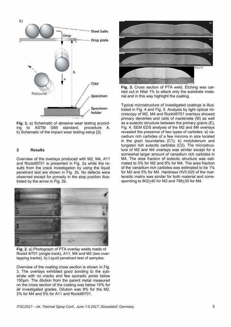
Low stress abrasive wear testing was performed ac-cording to ASTM G65 standard, procedure A [2], by using a commercial multiplex sand/wheel abrasion tri-bometer (Phoenix tribology TE 65). A schematic of the testing is illustrated in Fig. 1a. Five sample replicas per material were tested. Impact wear testing was performed by using an in-house build tribometer. The schematic is shown in Fig. 1b [3]. Standard steel bearing balls drop from pre-defined heights onto the coated test specimen. A data point corresponds to the total number of ball strikes for a pre-defined height i.e. impact energy until occur-rence of a first circular crack around the impact dent. This type of model impact wear testing is suitable to rank impact wear resistance of materials exposed to impact overloads at relatively low impact velocities. Operation conditions closest to the modelling in this testing can be exemplified by a first contact of the ex-cavator bucket teeth with the ground; by filling of the excavator buckets by the dig-out material; by forward-ing the dig-out material to the truck bed etc. Abrasive wear is removed from this testing in difference to a combined abrasive-impact wear testing [4].
ITSC2017 – Int. Thermal Spray Conf., June 7-9 2017, Düsseldorf, Germany. 3
Fig. 1. a) Schematic of abrasive wear testing accord-ing to ASTM G65 standard, procedure A. b) Schematic of the impact wear testing setup [3]. 3 Results Overview of the overlays produced with M2, M4, A11 and Rockit®701 is presented in Fig. 2a while the re-sults from the crack investigation by using the liquid penetrant test are shown in Fig. 2b. No defects were observed except for porosity in the stop position illus-trated by the arrow in Fig. 2b.
Fig. 2. a) Photograph of PTA overlay welds made of Rockit ®701 (single track), A11, M4 and M2 (two over-lapping tracks). b) Liquid penetrant test of samples. Overview of the coating cross section is shown in Fig. 3. The overlays exhibited good bonding to the sub-strate with no cracks and few sporadic pores below 100µm. The dilution from the parent metal measured on the cross section of the coating was below 15% for all investigated grades. Dilution was 8% for the M2, 2% for M4 and 5% for A11 and Rockit®701.
Fig. 3. Cross section of PTA weld. Etching was car-ried out in Nital 1% to attack only the substrate mate-rial and in this way highlight the coating. Typical microstructure of investigated coatings is illus-trated in Fig. 4 and Fig. 5. Analysis by light optical mi-croscopy of M2, M4 and Rockit®701 overlays showed primary dendrites and cells of martensite (M) as well as a eutectic structure between the primary grains (E), Fig. 4. SEM EDS analysis of the M2 and M4 overlays revealed the presence of two types of carbides: a) va-nadium rich carbides of a few microns in size located in the grain boundaries (C1); b) molybdenum and tungsten rich eutectic carbides (C2). The microstruc-ture of M2 and M4 overlays was similar except for a somewhat larger amount of vanadium rich carbides in M4. The area fraction of eutectic structure was esti-mated to 5% for M2 and 8% for M4. The area fraction of the vanadium rich carbides was estimated to be 1% for M2 and 5% for M4. Hardness HV0.025 of the mar-tensitic matrix was similar for both material and corre-sponding to 802+40 for M2 and 798+30 for M4.

ITSC2017 – Int. Thermal Spray Conf., June 7-9 2017, Düsseldorf, Germany. 4
Fig. 4. Light optical micrograph of a cross section of the investigated overlays. a) M2; b) M4; c) A11; d) Rockit ®701 (a-d are etched in Vilella); e) MMC over-lay, oxide polished using colloidal SiO2, lower magnifi-cation than for the iron based coatings. Examination of Rockit® 701 by light optical microsco-py showed a martensitic matrix (M) with a hard phase network bewteen the martensitic grains (E), Fig. 4d. SEM EDS analysis showed the presence different primary hard phase particles, Fig. 5d: a) niobium rich carbides (C); b) tungsten rich borides (B); c) Cr rich eutectic carbides (E). Size of the eutectic islands was up to approximately 15 μm, size of the tungsten rich boride areas was up to 10 μm and finally the primary carbides were in the range of 1 micron. The area frac-tion of hard phase including the eutectic structure was
estimated to be 30%, whereof 3% consisted of niobi-um rich carbides. Hardness HV0.025 of the martensit-ic matrix was 830+30.
Fig. 5. SEM micrograph of a cross section of the iron based overlays as-oxide polished. a) M2; b) M4; c) A11; d) Rockit® 701.
Microstructure of A11 is illustrated in Fig. 4c and 5c. In A11 solidification started with the formation of primary vanadium rich carbides followed by the formation of primary austenitic dendrites and cells transforming in-to martensite upon cooling. Very small amounts of chromium and molybdenum rich carbides were ob-served in the grain boundaries (C3). Some retained austenite was found at the periphery of the martensitic grains (A). The area fraction of the primary vanadium rich carbides was 20%. The vanadium rich carbides were evenly distributed along the coating; they were rounded in shape and roughly 2µm in size. The microstructure of the MMC overlays consisted of coarse WC particles embedded in a NiSiB matrix con-sisting of austenitic primary dendrites and mainly Ni-Si-B eutectic structure, Fig. 4e. Dissolution of the car-bides during overlay welding was limited and mainly localized in an area of few microns in depth at the pe-
e
a)
b)
c)
d)
C3

ITSC2017 – Int. Thermal Spray Conf., June 7-9 2017, Düsseldorf, Germany. 5
riphery of the WC particles, as indicated by the arrow in Fig. 4e. Estimated area fraction of the tungsten car-bide particles was 35%. Hardness HRC and abrasive wear measured accord-ing to ASTM G65 – Procedure A, for the investigated materials is presented in Fig. 6a. Rockit®701 showed highest hardness - 65 HRC. The high speed steels M2, M4 and A11 showed similar hardness, 61 HRC for M2 and M4 and 60 HRC for A11. Abrasive wear was lowest, 8 mm3, for the MMC overlay with 50wt% WC. Rockit®701 and A11 showed similar abrasive wear of 17 mm3 while M4 showed a wear of 45 mm3 and finally M2 a wear of >50 mm3. The impact energy as a function of the number of strikes needed to achieve the first crack in 50% of the tests is shown in Fig. 6b. Rockit®701 overlay showed a higher overload capacity and about ten times longer survival time than the MMC overlay.
Fig. 6. a) Low stress abrasive wear (ASTM G65, pro-cedure A) and hardness HRC for M2, M4, A11, Rock-it® 701 and MMC overlays. b) Impact energy as a function of number of strikes to achieve first crack in 50% of the tests. SEM analysis of the wear track after abrasive wear testing showed typical ploughing marks – scratches by the silica sand abradent, Fig. 7. The ploughs had a uniform direction in all overlays except for the MMC one. In the MMC overlay, abrasion of the nickel-based matrix around the tungsten carbide particles and rounding of the carbide edges were observed. For the iron-based overlays instead removal of the matrix and hard phase particles was more even. Mapping of the alloying elements in the wear scar by EDS showed that the asperities present (white arrows in Fig 7),
were mainly vanadium rich carbides in M4 and A11 and niobium rich as well as tungsten rich hard phase particles in Rockit®701. 5 Discussion The hardness of the iron-based overlays was, as ex-pected, not in correlation with abrasive wear re-sistance. Instead, the wear was in correlation with the properties of the hard phase particles formed during solidification from the melt. M2, M4 and A11 overlays showed similar hardness of 60-61 HRC but different wear, 17mm3 for A11, 40mm3 for M2 and >50mm3 for M2. Rockit®701 instead showed highest hardness but it performed similar to A11 in the low stress abrasive wear test. All overlays showed a martensitic matrix with similar hardness. Main difference between the iron-based grades was the type and amount of hard phase particles present in the overlay. The M4 overlay showed a larger amount of hard phase than M2. Further size of the carbides was somewhat coarser in M4. The higher vanadium con-tent resulted in the formation of a slightly larger amount of vanadium rich carbides in M4. The vanadi-um rich carbides are most probably hard and abrasive wear resistant MC carbides [5, 6]. Typical Vickers hardness for VC is 2700 [7]. The molybdenum and tungsten rich carbides present in the eutectic struc-tures were most probably relatively soft M6C or M2C carbides (1500-2000 HV0,025), less abrasive wear resistant than vanadium rich MC carbides [5, 6]. This was confirmed by analysis of the wear track showing least wear for the vanadium rich carbides. The in-creased amount of eutectic structure and mainly of vanadium rich carbides substantially increased the abrasive wear resistance of M4 compared to M2, without affecting the coating hardness. M2 and M4 showed lower resistance to abrasive wear than A11 and Rockit®701 due to the smaller volume fraction of hard phase particles combined with the small amount of hard vanadium rich carbides. The hard phase particles contributing to the abrasive wear resistance of Rockit®701 overlay were mainly the primary niobium rich MC carbides and tungsten rich borides, probably M2B [5] as confirmed by the analysis of the wear track. Typical Vickers hardness for NbC is 2000 [6], while for W2B it is 23,7GPa corre-sponding to 2400HV [8]. The chromium rich carbides present in the eutectic structure were most probably relatively soft M23C6 [5]. Hardness of these carbides is in the range of
a)

ITSC2017 – Int. Thermal Spray Conf., June 7-9 2017, Düsseldorf, Germany. 6
Fig. 7. Morphology of wear scars and elemental map-ping of the hard phase particles. a) M4, wear scar morphology; b) M4, elemental mapping of V c) A11 wear scar morphology; d) A11 elemental mapping of V; e)
Rockit®701 wear scar morphology; f) Rockit®701 el-emental mapping of Nb and W; g) 1559-40 + 50wt% 4580 wear scar morphology 1000HV [6] and very similar to that of the matrix. In A11, the vanadium rich, MC, carbides provided re-sistance to abrasive wear. These carbides were hard-er than the hard phase particles formed in Rock-it®701. The higher hardness and even distribution of the vanadium rich, carbides, formed in A11, could ex-plain why the wear resistance of A11 was similar to that of Rockit ®701 despite the total volume fraction of hard phase particles was smaller in A11. The lower HRC hardness, measured on A11, when compared to Rockit®701, could be due to the smaller volume frac-tion of hard phase particles in A11 combined with the presence of retained austenite. In the abrasive wear test the MMC overlay outper-formed the iron based grades showing 50% less wear than A11 and Rockit®701. The area fraction of the tungsten carbide particles in the MMC overlays was 5% larger than in Rockit®701 and 15% larger than in A11. Further, the nickel-based matrix consisted mainly of NiSiB eutectic. Another major difference between the MMC and iron based overlays was the size of the hard phase particles. Size of the tungsten carbide par-ticles in the MMC overlay was 53-150 µm while that of the hard phase particles in the iron-based coatings was in the range of a few microns. Finally, size of the abrading silica sand particles was 212-425 µm. For the MMC overlay, the abrading silica sand particles bridged over the hard phase particles. The matrix wear occurred by ploughing on surface areas where the bridge could not be established due to less dense distribution of the hard phase particles and /or by abrasion caused by oblong silica sand particles. The highest abrasive wear resistance of the MMC overlay was due the larger area fraction of hard phase com-bined with the larger size of the tungsten carbide par-ticles. Impact wear resistance of Rockit®701 and MMC over-lays differed at high impact energies, such as 10 to 30 J, but appeared to be similar approaching low im-pact energies such as 5J. It is known that impact load-ing affects inertia of the microstructure constituents, which “flows” through the deforming region in the im-pact stress field [10]. Relatively large and heavy hard phase particles, tungsten carbide, more than twice heavier in comparison to nickel based matrix, likely accelerated crack formation in MMC overlay at high impact energies/velocities. Low impact energies, such as 5 J, did not cause crack formations. In contrast, Rockit®701 overlay included much smaller hard phase particles, which as shown, resulted in less cracking. 6 Conclusions Properties of PTA welded iron based hardfacing grades with different amounts of chromium, vanadium, molybdenum, tungsten, carbon and boron were inves-
a)
b)
c)
d)
e)
f)
g)

ITSC2017 – Int. Thermal Spray Conf., June 7-9 2017, Düsseldorf, Germany. 7
tigated and compared with those of a NiSiB overlay with 50 wt. % macrocrystalline tungsten carbides.
The investigated iron based grades performed well during PTA welding and sound clads with nei-ther cracks nor critical porosity or other types of discontinuities were produced.
Hardness of the investigated iron based overlays
is not a measure of their low stress abrasive wear resistance. Type and amount of hard phase parti-cles are the major factors affecting abrasive wear resistance, if size is similar.
M2, M4 and A11 overlays exhibit similar hardness
but abrasive wear is 17mm3 for A11, 40 mm3 for M2 and >50 mm3 for M2. Rockit®701 hardness is 5 HRC units higher than for A11 but the abrasive wear resistance is similar for both grades.
For low stress abrasion, nickel-based coatings
with admixed tungsten carbides outperform the iron-based grades. However, the iron based grade Rockit®701 shows a larger ability to take impact, when compared to a nickel based coating with 50 wt.% WC.
7 Acknowledgements The author would like to thank Peter Olsérius, Mattias Weibull and Marcus Ewald for support in the prepara-tion and evaluation of the investigated samples. 8 Literature [1] ASM Handbook on line, Welding, Brazing and Sol-dering, Vol. 6 [2] ASTM G65: Standard Test Method for Measuring Abrasion Using the Dry Sand/Rubber Wheel Appa-ratus, 2010. [3] S. Bengtsson, S. Dizdar, B. Maroli, L. Baguette “New hardfacing material with high impact wear re-sistance” ITSC 2016, Shanghai [4] Abrasive impact wear and surface fatigue wear behaviour of Fe–Cr–C PTA overlays, Wear 301(2013) 102-108. [5] Termo-Calc 2016a, Thermocal Software AB [6] H. Brandis et al. “Metallurgical aspects of Carbides in High Speed Steels” Thyssen Edelst. Techn. Ber., 1983 [7] A.T. Santhanam, P. Tierney, and J.L. Hunt, Ce-mented Carbides, Properties and Selection: Nonfer-rous Alloys and Special-Purpose Materials, Vol 2, ASM Handbook, ASM International, 1990, p 950–977 [8] Crystallography and Engineering Properties of Ce-ramics, Engineered Materials Handbook Desk Edition, ASM International, 1995, p. 922–975 [9] O. Pierson, “Handbook of refractory carbides and nitrides”, Noyes Publications, 2009 [10] K.L. Johnson, Contact mechanics, Cambridge university press, Cambridge, 1985.
[11] M. Kirchgassner “Behaviour of iron-based hard-facing alloys under abrasion and impact” Wear 265 (2008) 772–779 [12] Powder mix: 1559-00 / 4580 in “Thermal Surfac-ing: Powder Choice with Ease”, Höganäs AB, 2016