ironridge ground mount manual
TRANSCRIPT
GROUND MOUNT
INSTALLATION MANUAL

CONTeNTS
GROUND MOUNT INSTALLATION MANUAL - 1© 2021 IRONRIDGE, INC. VERSION 3.1
DISCLAIMeR 1RATINGS 2MARKINGS 2CHeCKLIST 31. BUILD BASe 4 1. BUILD BASe 52. CONNeCT SUBSTRUCTURe 53. PLACe RAILS 6 4. SeCURe LUGS 6 5. SeCURe MODULeS 7CAMO 8eLeCTRICAL DIAGRAM 9DIAGONAL BRACeS (OPTIONAL) 10eND CAPS 10WIRe CLIPS 10SPLICING HORIZONTAL BeAMS 11MICROINVeRTeR KITS 12SYSTeMS USING eNPHASe MICROINVeRTeRS OR SUNPOWeR AC MODULeS 12SYSTeMS USING MICROSTORAGe PRODUCTS 13FRAMeLeSS MODULe KITS 13MODULe COMPATIBILITY 14-18 FRAMLeSS MODULe COMPATIBILITY 19
DISCLAIMeR
This manual describes proper installation procedures and provides necessary standards required for product reliability. Warranty details are available on website. All installers must thoroughly read this manual and have a clear understanding of the installation procedures prior to installation. Failure to follow these guidelines may result in property damage, bodily injury or even death.
IT IS THe INSTALLeR’S ReSPONSIBILITY TO:
• Ensure safe installation of all electrical aspects of the array. All electrical installation and procedures should be conducted by a licensed and bonded electrician or solar contractor. Routine maintenance of a module or panel shall not involve breaking or disturbing the bonding path of the system. All work must comply with national, state and local installation procedures, product and safety standards.
• Comply with all applicable local or national building and fire codes, including any that may supersede this manual.• Ensure all products are appropriate for the installation, environment, and array under the site’s loading conditions.• Use only IronRidge parts or parts recommended by IronRidge; substituting parts may void any applicable warranty.• Review the Design Assistant and Certification Letters to confirm design specifications.• Ensure provided information is accurate. Issues resulting from inaccurate information are the installer’s responsibility.• Validate foundation parameters prior to installation, as a local geotechnical report may be required to assess ground
conditions. We recommend consulting with a local engineer familiar with local regulations and build site requirements, including soil conditions, terrain and load criteria. All parameters may impact foundation requirements.
• Ensure bare copper grounding wire does not contact aluminum and zinc-plated steel components, to prevent risk of galvanic corrosion.
• If loose components or loose fasteners are found during periodic inspection, re-tighten immediately. Any components showing signs of corrosion or damage that compromise safety shall be replaced immediately.
• Provide an appropriate method of direct-to-earth grounding according to the latest edition of the National Electrical Code, including NEC 250: Grounding and Bonding, and NEC 690: Solar Photovoltaic Systems.
• Disconnect AC power before servicing or removing modules, AC modules, microinverters and power optimizers.• Review module manufacturer’s documentation for compatibility and compliance with warranty terms and conditions.
GROUND MOUNT INSTALLATION MANUAL - 2© 2021 IRONRIDGE, INC. VERSION 3.1
RATINGS
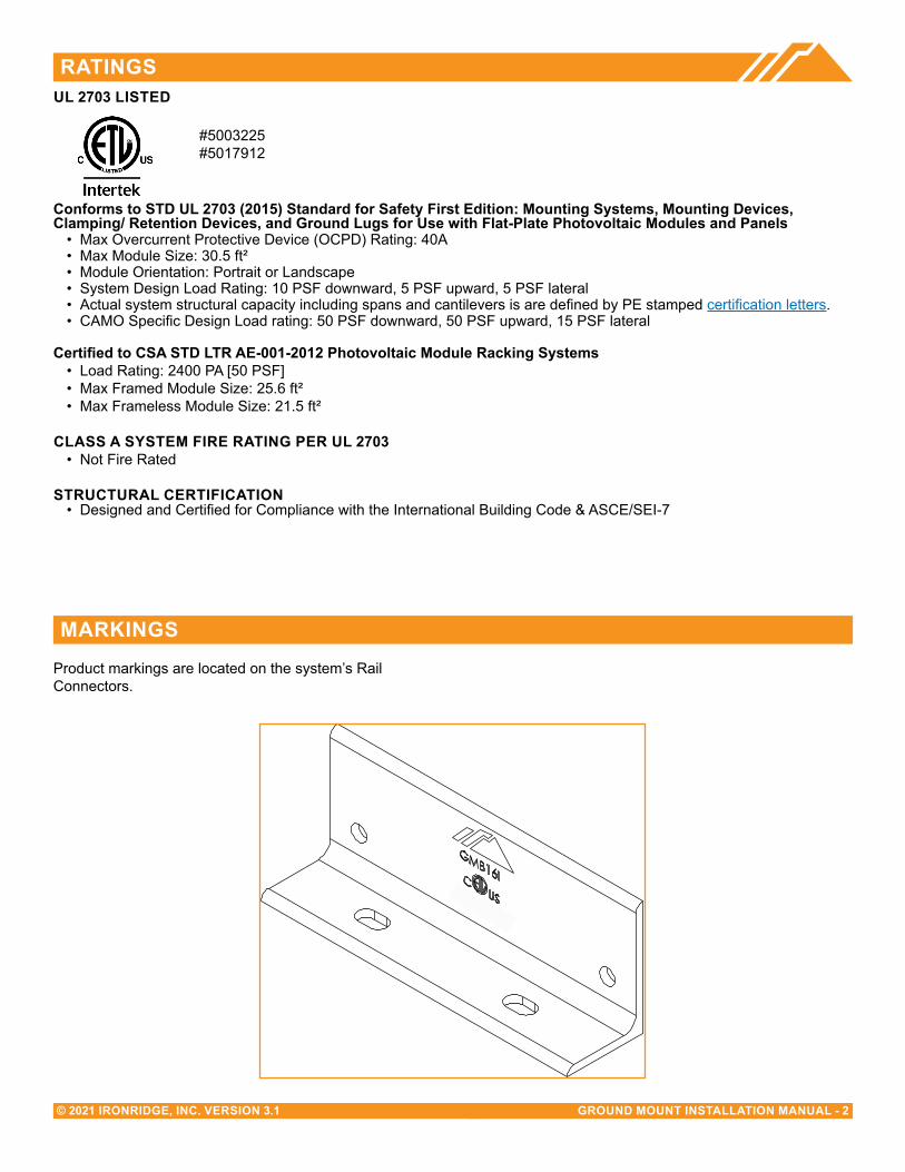
MARKINGSProduct markings are located on the system’s Rail Connectors.
UL 2703 LISTeD
Conforms to STD UL 2703 (2015) Standard for Safety First edition: Mounting Systems, Mounting Devices, Clamping/ Retention Devices, and Ground Lugs for Use with Flat-Plate Photovoltaic Modules and Panels
• Max Overcurrent Protective Device (OCPD) Rating: 40A• Max Module Size: 30.5 ft²• Module Orientation: Portrait or Landscape• System Design Load Rating: 10 PSF downward, 5 PSF upward, 5 PSF lateral• Actual system structural capacity including spans and cantilevers is are defined by PE stamped certification letters.• CAMO Specific Design Load rating: 50 PSF downward, 50 PSF upward, 15 PSF lateral
Certified to CSA STD LTR AE-001-2012 Photovoltaic Module Racking Systems• Load Rating: 2400 PA [50 PSF]• Max Framed Module Size: 25.6 ft²• Max Frameless Module Size: 21.5 ft²
CLASS A SYSTeM FIRe RATING PeR UL 2703• Not Fire Rated
STRUCTURAL CeRTIFICATION• Designed and Certified for Compliance with the International Building Code & ASCE/SEI-7
#5003225#5017912

GROUND MOUNT INSTALLATION MANUAL - 3© 2021 IRONRIDGE, INC. VERSION 3.1
CHeCKLIST
IRONRIDGe COMPONeNTSPRe-INSTALLATION
☐ Verify module compatibility. See Page 14 for info.
☐ Purchase 2” or 3” Pipe or Mechanical Tubing
Pipe: 2” or 3” (NPS) ASTM A53 Grade B SCH 40 Pipe, galvanized to a min of ASTM A653 G90 or ASTM A123 G35.Mechanical Tubing: 2.375” x 12 ga (O.D) or 3.500” x 8 ga (O.D.) Mechanical Tubing with one of the following Galvinizations (ASTM A1057).
• Allied Gatorshield • Allied Flo-Coat Coating• Wheatland ThunderCoat
TOOLS ReQUIReD ☐ Post Hole Digger or Powered Auger ☐ Socket Drive (7/16”, 9/16”, and 1/2” Sockets) ☐ Torque Wrenches (0-240 in-lbs and 10-40 ft-lbs) ☐ Transit, String Line, or Laser Level ☐ 3/16” Allen Head
TORQUe VALUeS
Top Cap Set Screws (3/16” Allen Head) ☐ 2” or 3” NPS Schedule 40 Grade B Pipe: 20 ft-lbs ☐ 2.375” x 12 ga OD Mechanical Tubing: 11 ft-lbs ☐ 3.500” x 8 ga OD Mechanical Tubing: 16 ft-lbs
☐ For Ground Screw to Pipe Connection Hardware see Page 5.
☐ Top Cap U-Bolt Nuts (9/16” Socket): 15 ft-lbs ☐ Rail Connector Bracket Nuts (9/16” Socket): 21 ft-lbs ☐ Rail Connector U-Bolt Nuts (9/16” Socket): 60 in-lbs ☐ Rail Grounding Lug Nut (7/16” Socket): 80 in-lbs
☐ Rail Grounding Lug Terminal Screws (7/16” Socket): 20 in-lbs
☐ Module Grounding Lug Nut (3/8” Socket): 60 in-lbs ☐ Module Grounding Lug Terminal Screws (1/2”
Socket): 20 in-lbs ☐ Universal Fastening Objects (7/16” Socket): 80 in-lbs ☐ Diagonal Brace Set Screws (1/2” Socket): 15 ft-lbs ☐ Diagonal Brace Bolts (1/2” Socket): 40 ft-lbs ☐ Microinverter Kit Nuts (7/16” Socket): 80 in-lbs ☐ Frameless Module Kit Nuts (7/16” Socket): 80 in-lbs
➢ If using previous version of: Integrated Grounding Mid Clamps, Grounding Lug and end Clamps please refer to Alternate Components Addendum (Version 1.80).
➢ If installing on a low slope roof please refer to Ground Mount for Flat Roof Applications Addendum (Version 2.80).
➢ Unless otherwise noted, all components have been evaluated for multiple use. They can be uninstalled and reinstalled in the same or new location.
XR100 & XR1000 Rail Rail Connector
Top Cap UFO
Diagonal Brace
Stopper Sleeve
Rail Grounding Lug
Microinverter Kit
Frameless Module Kit
Frameless End/Mid Clamp
CAMO
End Cap Wire Clip
Module Grounding Lug
Hex Head Set Screw
GROUND MOUNT INSTALLATION MANUAL - 4© 2021 IRONRIDGE, INC. VERSION 3.1
PIPe SPeCIFICATIONS
A. MARK LOCATIONS
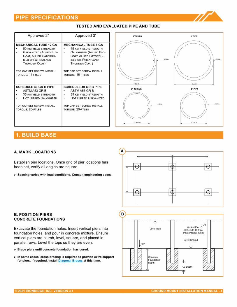
Establish pier locations. Once grid of pier locations has been set, verify all angles are square.
➢ Spacing varies with load conditions. Consult engineering specs.
B. POSITION PIeRSCONCReTe FOUNDATIONS
Excavate the foundation holes. Insert vertical piers into foundation holes, and pour in concrete mixture. Ensure vertical piers are plumb, level, square, and placed in parallel rows. Level the tops so they are even.
➢ Brace piers until concrete foundation has cured.
➢ In some cases, cross bracing is required to provide extra support for piers. If required, install Diagonal Braces at this time.
A
B
Level Tops Vertical Pier(Schedule 40 Pipe
or Mechanical Tube)
Level Ground
90°
1/3 Depth
ConcreteFoundation Depth
1. BUILD BASe
TeSTeD AND eVALUATeD PIPe AND TUBe
.216 in
3.5 in
3" PIPE
.154 in
2.375 in
3" pipe
.165 in
3.5 in
3" TUBING
.109 in
2.375 in
2" Tubing
Approved 2” Approved 3”
MeCHANICAL TUBe 12 GA• 50 ksi yield strength• Galvanized (Allied Flo-
Coat, Allied Gatorsh-ield or Wheatland Thunder Coat)
top cap set screw install torque: 11-ftlbs
MeCHANICAL TUBe 8 GA• 45 ksi yield strength• Galvanized (Allied Flo-
Coat, Allied Gatorsh-ield or Wheatland Thunder Coat)
top cap set screw install torque: 16-ftlbs
SCHeDULe 40 GR B PIPe• ASTM A53 GR B• 35 ksi yield strength• Hot Dipped Galvanized
top cap set screw install torque: 20-ftlbs
SCHeDULe 40 GR B PIPe• ASTM A53 GR B• 35 ksi yield strength• Hot Dipped Galvanized
top cap set screw install torque: 20-ftlbs
2” PIPe2” TUBING
1. BUILD BASe
GROUND MOUNT INSTALLATION MANUAL - 5© 2021 IRONRIDGE, INC. VERSION 3.1
1. BUILD BASe (CONT.)
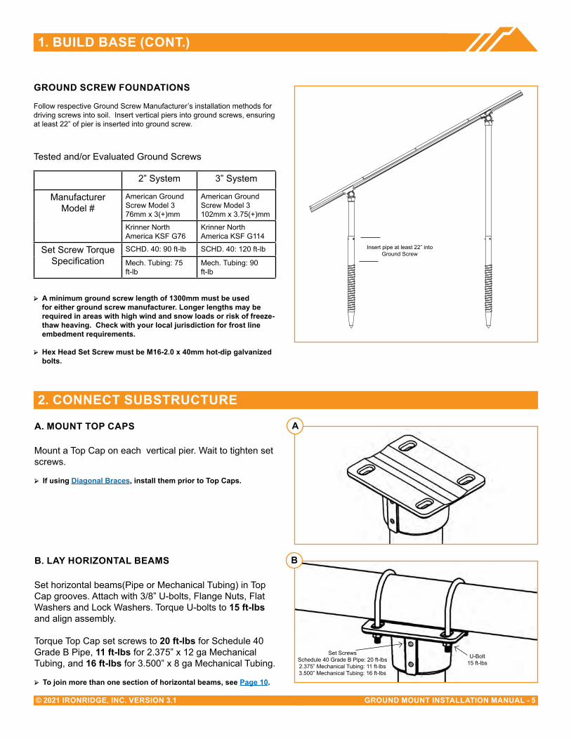
A. MOUNT TOP CAPS
Mount a Top Cap on each vertical pier. Wait to tighten set screws.
➢ If using Diagonal Braces, install them prior to Top Caps.
B. LAY HORIZONTAL BeAMS
Set horizontal beams(Pipe or Mechanical Tubing) in Top Cap grooves. Attach with 3/8” U-bolts, Flange Nuts, Flat Washers and Lock Washers. Torque U-bolts to 15 ft-lbs and align assembly.
Torque Top Cap set screws to 20 ft-lbs for Schedule 40 Grade B Pipe, 11 ft-lbs for 2.375” x 12 ga Mechanical Tubing, and 16 ft-lbs for 3.500” x 8 ga Mechanical Tubing.
➢ To join more than one section of horizontal beams, see Page 10.
2. CONNeCT SUBSTRUCTURe
A
B
U-Bolt15 ft-lbs
Set ScrewsSchedule 40 Grade B Pipe: 20 ft-lbs2.375” Mechanical Tubing: 11 ft-lbs3.500” Mechanical Tubing: 16 ft-lbs
GROUND SCReW FOUNDATIONS
Follow respective Ground Screw Manufacturer’s installation methods for driving screws into soil. Insert vertical piers into ground screws, ensuring at least 22” of pier is inserted into ground screw.
Tested and/or Evaluated Ground Screws
2” System 3” System
Manufacturer Model #
American Ground Screw Model 3 76mm x 3(+)mm
American Ground Screw Model 3102mm x 3.75(+)mm
Krinner North America KSF G76
Krinner North America KSF G114
Set Screw Torque Specification
SCHD. 40: 90 ft-lb SCHD. 40: 120 ft-lb
Mech. Tubing: 75 ft-lb
Mech. Tubing: 90 ft-lb
➢ A minimum ground screw length of 1300mm must be used for either ground screw manufacturer. Longer lengths may be required in areas with high wind and snow loads or risk of freeze-thaw heaving. Check with your local jurisdiction for frost line embedment requirements.
➢ Hex Head Set Screw must be M16-2.0 x 40mm hot-dip galvanized bolts.
Insert pipe at least 22” into Ground Screw
GROUND MOUNT INSTALLATION MANUAL - 6© 2021 IRONRIDGE, INC. VERSION 3.1
3. PLACe RAILS
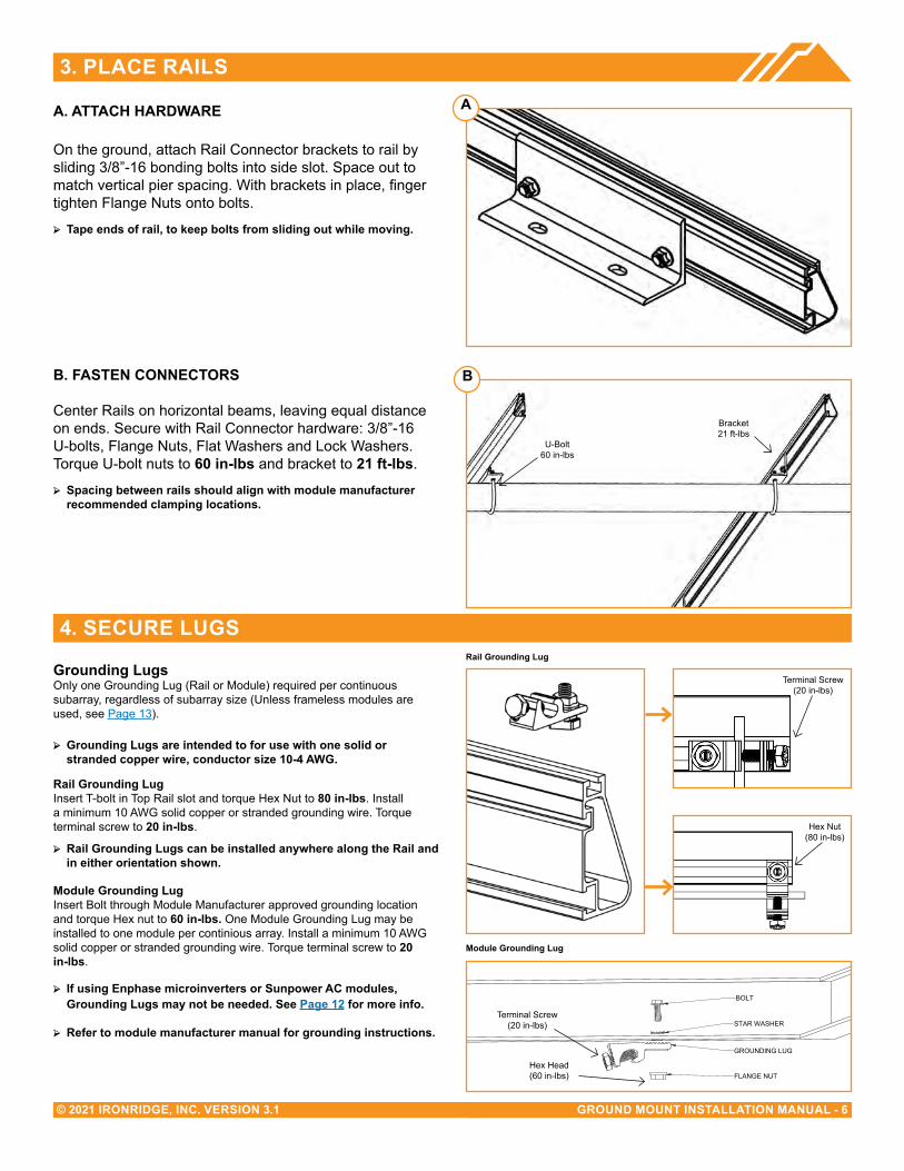
A. ATTACH HARDWARe
On the ground, attach Rail Connector brackets to rail by sliding 3/8”-16 bonding bolts into side slot. Space out to match vertical pier spacing. With brackets in place, finger tighten Flange Nuts onto bolts.
➢ Tape ends of rail, to keep bolts from sliding out while moving.
B. FASTeN CONNeCTORS
Center Rails on horizontal beams, leaving equal distance on ends. Secure with Rail Connector hardware: 3/8”-16 U-bolts, Flange Nuts, Flat Washers and Lock Washers. Torque U-bolt nuts to 60 in-lbs and bracket to 21 ft-lbs.
➢ Spacing between rails should align with module manufacturer recommended clamping locations.
4. SeCURe LUGS
A
U-Bolt60 in-lbs
Bracket21 ft-lbs
Hex Nut(84 in-lbs)
Terminal Screw(20 in-lbs)
Hex Nut(80 in-lbs)
B
FLANGE NUT
GROUNDING LUG
BOLT
STAR WASHERTerminal Screw
(20 in-lbs)
Hex Head(60 in-lbs)
Module Grounding Lug
Rail Grounding LugGrounding LugsOnly one Grounding Lug (Rail or Module) required per continuous subarray, regardless of subarray size (Unless frameless modules are used, see Page 13).
➢ Grounding Lugs are intended to for use with one solid or stranded copper wire, conductor size 10-4 AWG.
Rail Grounding LugInsert T-bolt in Top Rail slot and torque Hex Nut to 80 in-lbs. Install a minimum 10 AWG solid copper or stranded grounding wire. Torque terminal screw to 20 in-lbs.
➢ Rail Grounding Lugs can be installed anywhere along the Rail and in either orientation shown.
Module Grounding LugInsert Bolt through Module Manufacturer approved grounding location and torque Hex nut to 60 in-lbs. One Module Grounding Lug may be installed to one module per continious array. Install a minimum 10 AWG solid copper or stranded grounding wire. Torque terminal screw to 20 in-lbs.
➢ If using enphase microinverters or Sunpower AC modules, Grounding Lugs may not be needed. See Page 12 for more info.
➢ Refer to module manufacturer manual for grounding instructions.
GROUND MOUNT INSTALLATION MANUAL - 7© 2021 IRONRIDGE, INC. VERSION 3.1
5. SeCURe MODULeS
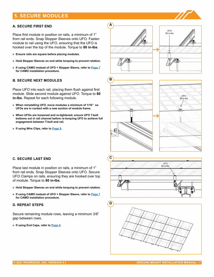
A. SeCURe FIRST eND
Place first module in position on rails, a minimum of 1” from rail ends. Snap Stopper Sleeves onto UFO. Fasten module to rail using the UFO, ensuring that the UFO is hooked over the top of the module. Torque to 80 in-lbs.
➢ ensure rails are square before placing modules.
➢ Hold Stopper Sleeves on end while torquing to prevent rotation.
➢ If using CAMO instead of UFO + Stopper Sleeve, refer to Page 7 for CAMO installation procedure.
B. SeCURe NeXT MODULeS
Place UFO into each rail, placing them flush against first module. Slide second module against UFO. Torque to 80 in-lbs. Repeat for each following module.
➢ When reinstalling UFO, move modules a minimum of 1/16” so UFOs are in contact with a new section of module frame.
➢ When UFOs are loosened and re-tightened, ensure UFO T-bolt bottoms out in rail channel before re-torquing UFO to achieve full engagement between T-bolt and rail.
➢ If using Wire Clips, refer to Page 9.
C. SeCURe LAST eND
Place last module in position on rails, a minimum of 1” from rail ends. Snap Stopper Sleeves onto UFO. Secure UFO Clamps on rails, ensuring they are hooked over top of module. Torque to 80 in-lbs.
➢ Hold Stopper Sleeves on end while torquing to prevent rotation.
➢ If using CAMO instead of UFO + Stopper Sleeve, refer to Page 7 for CAMO installation procedure.
D. RePeAT STePS
Secure remaining module rows, leaving a minimum 3/8” gap between rows.
➢ If using end Caps, refer to Page 9.
A
B
C
D
UFO80 in-lbs
UFO80 in-lbs
UFO80 in-lbs

GROUND MOUNT INSTALLATION MANUAL - 8© 2021 IRONRIDGE, INC. VERSION 3.1
CAMO
A. SLIDe INTO RAIL
Slide CAMO into rail channel far enough to clear the module frame. CAMO requires 6" of clearance from end of rail.
B. PLACe MODULe
Place module on rails (module cells not shown for clarity). When installing CAMO the module can overhang the rail no more than 1/4”.
C. PULL TOWARDS eND
Pull CAMO towards rail ends, at 45 degree angle, so the bonding bolt contacts the module flange edge.
D. SeCURe TO FRAMe
Rotate handle with an upwards motion until CAMO snaps into rail channel. Ensure CAMO bonding pins are fully seated on top of module frame.
FRAMe COMPATIBILITY
CAMO has been tested or evaluated with all modules listed in the Module Compatibility section having frames within the referenced dimensions. Be sure the specific module being used meets the dimension requirements.
➢ For installations with Hanwha Q CeLLS modules with 32 mm frame heights, the maximum ground snow is 45 PSF (33 PSF module pressure).
➢ CAMO’s compatiblity with Canadian Solar modules is limited to the HiDM5 (CS1Y) modules.
A
B
C
D
6" Clearance
GROUND MOUNT INSTALLATION MANUAL - 9© 2021 IRONRIDGE, INC. VERSION 3.1
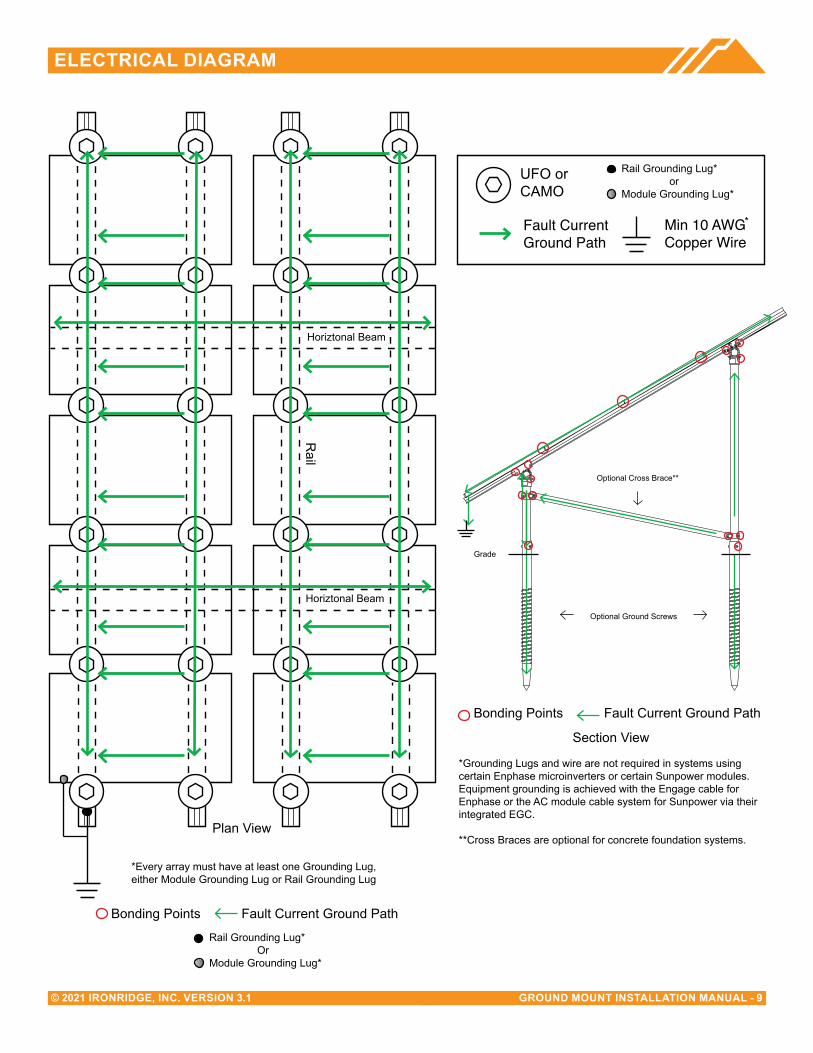
eLeCTRICAL DIAGRAM
UFO Clamp Grounding Lug
Min 10 AWGCopper Wire
Fault Current Ground Path
*
Plan View
*Every array must have at least one Grounding Lug, either Module Grounding Lug or Rail Grounding Lug
Rail
UFO or CAMO
Optional Cross Brace**
Grade
Bonding Points Fault Current Ground Path
*Grounding Lugs and wire are not required in systems using certain Enphase microinverters or certain Sunpower modules. Equipment grounding is achieved with the Engage cable for Enphase or the AC module cable system for Sunpower via their integrated EGC.
**Cross Braces are optional for concrete foundation systems.
Section View
Optional Ground Screws
Rail Grounding Lug* orModule Grounding Lug*
Bonding Points Fault Current Ground Path
Rail Grounding Lug* OrModule Grounding Lug*
Horiztonal Beam
Horiztonal Beam
GROUND MOUNT INSTALLATION MANUAL - 10© 2021 IRONRIDGE, INC. VERSION 3.1
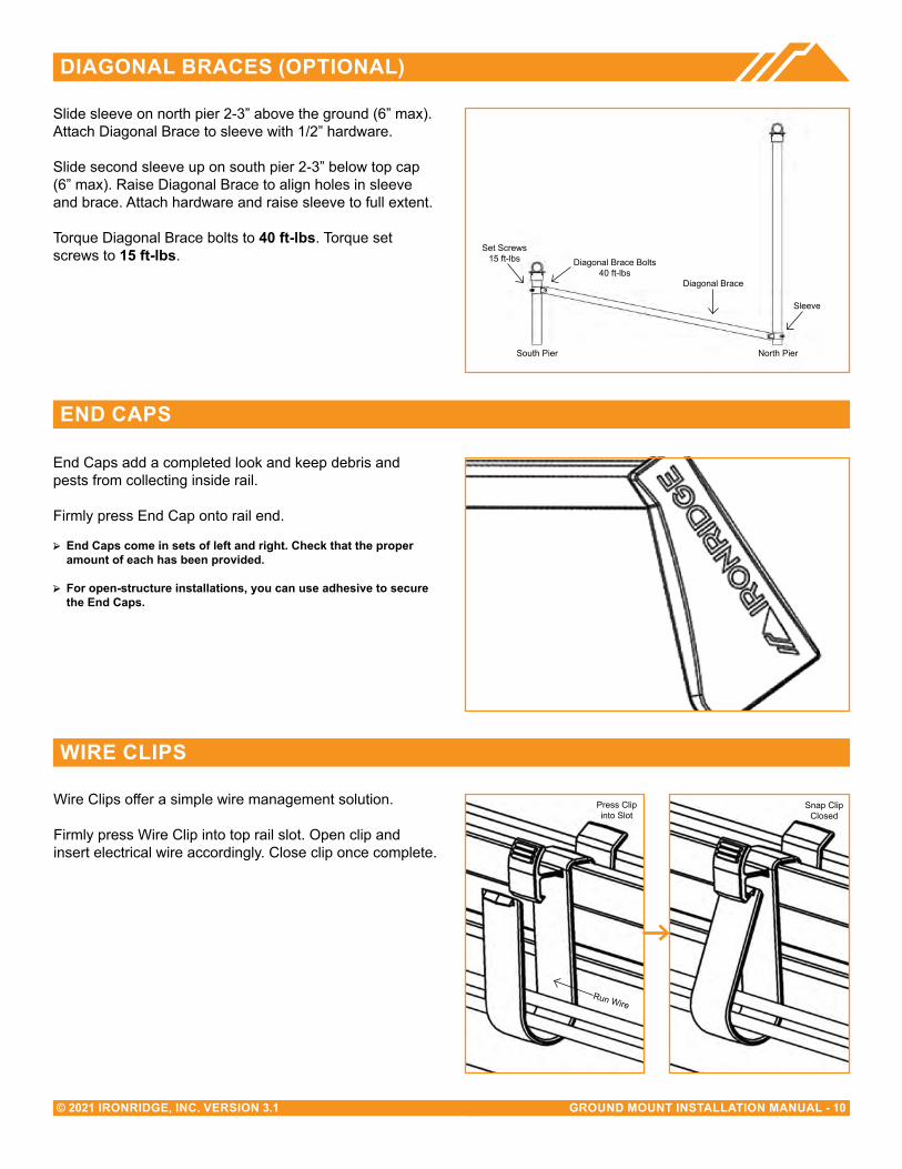
DIAGONAL BRACeS (OPTIONAL)
Slide sleeve on north pier 2-3” above the ground (6” max).Attach Diagonal Brace to sleeve with 1/2” hardware.
Slide second sleeve up on south pier 2-3” below top cap (6” max). Raise Diagonal Brace to align holes in sleeve and brace. Attach hardware and raise sleeve to full extent.
Torque Diagonal Brace bolts to 40 ft-lbs. Torque set screws to 15 ft-lbs.
eND CAPS
WIRe CLIPS
End Caps add a completed look and keep debris and pests from collecting inside rail.
Firmly press End Cap onto rail end.
➢ End Caps come in sets of left and right. Check that the proper amount of each has been provided.
➢ For open-structure installations, you can use adhesive to secure the end Caps.
Wire Clips offer a simple wire management solution.
Firmly press Wire Clip into top rail slot. Open clip and insert electrical wire accordingly. Close clip once complete.
South Pier North Pier
Diagonal Brace
Diagonal Brace Bolts40 ft-lbs
Set Screws15 ft-lbs
Sleeve
Press Clip into Slot
Run Wire
Snap Clip Closed

GROUND MOUNT INSTALLATION MANUAL - 11© 2021 IRONRIDGE, INC. VERSION 3.1
SPLICING CROSS PIPe
The following instructions should be followed, when required, to join more than one section of horizontal beam together to ensure bonding is maintained throughout the system.
A. MeCHANICAL TUBING SPLICeS
Mechanical tube splices shown in the table below shall be of equivalent Allied Flo-Coat, Allied Gatorshield or Wheat-land ThunderCoat coating.
Insert splice tube 6” into first section of cross tube and se-cure with 2 self-drilling screws (1/4”-14 x ¾”), spacing them approximately 1.25” from end of pipe and approximately 3.50” apart, tightening screws to 9 ft-lbs.
Slide second section of cross tube over splice tube and secure with two more self-drilling screws. Tighten screws to 9 ft-lbs.
➢ Pre-drill 5/32” pilot holes through cross tube and splice tube for easier installation of self-drilling screws.
B. SCHeDULe 40 GRADe B PIPe SPLICeS
Use galvanized threaded pipe couplings that match the pipe size used for the structure. Threaded Schedule 40 Grade B Pipe must be used when splicing cross pipe together.
Fully thread coupling onto both sections of pipe being spliced together.
➢ Splice cannot be installed in the cantilever, center 1/3 of interior spans, or the outer 2/3 of end spans.
C. HORIZONTAL PIPeS CAN Be JOINeD OVeR AN INTeRIOR TOP CAP WITH A MAXIMUM GAP OF 1/2”
➢ To avoid potential problems from the effects of thermal expansion, a maximum total continuous cross pipe length
of 100 ft is recommended.
Mechanical Tube Size of the Structure Splice Tube Size
2.375” OD, 12 Gauge 2.000” OD, 9 Gauge, Minimum 12” Long
3.500” OD, 8 Gauge 3.000” OD, 12 Gauge, Minimum 12” Long
A
B
C
Horizontal Beam
Horizontal Beam
Horizontal Beam Cross Beam
Horizontal Beam
Horizontal Beam
GROUND MOUNT INSTALLATION MANUAL - 12© 2021 IRONRIDGE, INC. VERSION 3.1
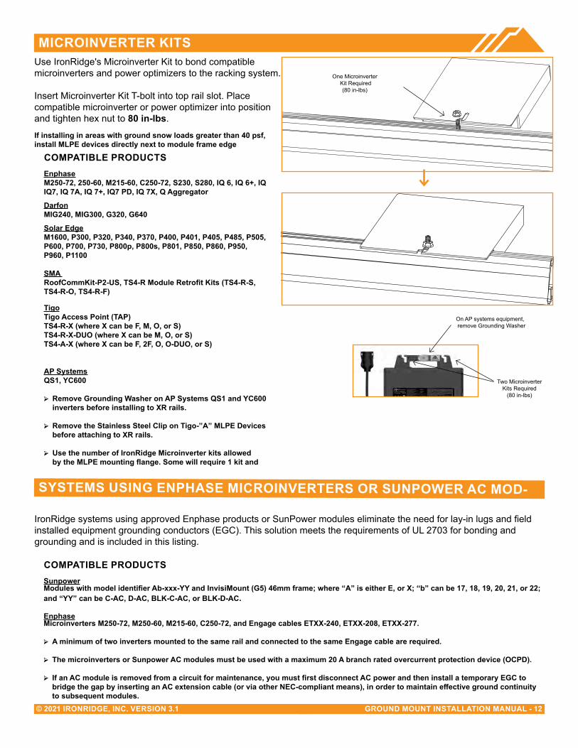
MICROINVeRTeR KITS
One Microinverter Kit Required
(80 in-lbs)
Use IronRidge's Microinverter Kit to bond compatible microinverters and power optimizers to the racking system.
Insert Microinverter Kit T-bolt into top rail slot. Place compatible microinverter or power optimizer into position and tighten hex nut to 80 in-lbs.
If installing in areas with ground snow loads greater than 40 psf, install MLPe devices directly next to module frame edge
SYSTeMS USING eNPHASe MICROINVeRTeRS OR SUNPOWeR AC MOD-
IronRidge systems using approved Enphase products or SunPower modules eliminate the need for lay-in lugs and field installed equipment grounding conductors (EGC). This solution meets the requirements of UL 2703 for bonding and grounding and is included in this listing.
COMPATIBLe PRODUCTSSunpowerModules with model identifier Ab-xxx-YY and InvisiMount (G5) 46mm frame; where “A” is either E, or X; “b” can be 17, 18, 19, 20, 21, or 22; and “YY” can be C-AC, D-AC, BLK-C-AC, or BLK-D-AC.
enphaseMicroinverters M250-72, M250-60, M215-60, C250-72, and engage cables eTXX-240, eTXX-208, eTXX-277.
➢ A minimum of two inverters mounted to the same rail and connected to the same engage cable are required.
➢ The microinverters or Sunpower AC modules must be used with a maximum 20 A branch rated overcurrent protection device (OCPD).
➢ If an AC module is removed from a circuit for maintenance, you must first disconnect AC power and then install a temporary EGC to bridge the gap by inserting an AC extension cable (or via other NEC-compliant means), in order to maintain effective ground continuity to subsequent modules.
On AP systems equipment, remove Grounding Washer
COMPATIBLe PRODUCTSenphaseM250-72, 250-60, M215-60, C250-72, S230, S280, IQ 6, IQ 6+, IQIQ7, IQ 7A, IQ 7+, IQ7 PD, IQ 7X, Q Aggregator
DarfonMIG240, MIG300, G320, G640
Solar edgeM1600, P300, P320, P340, P370, P400, P401, P405, P485, P505, P600, P700, P730, P800p, P800s, P801, P850, P860, P950, P960, P1100
SMA RoofCommKit-P2-US, TS4-R Module Retrofit Kits (TS4-R-S, TS4-R-O, TS4-R-F)
TigoTigo Access Point (TAP) TS4-R-X (where X can be F, M, O, or S) TS4-R-X-DUO (where X can be M, O, or S) TS4-A-X (where X can be F, 2F, O, O-DUO, or S)
AP SystemsQS1, YC600
➢ Remove Grounding Washer on AP Systems QS1 and YC600 inverters before installing to XR rails.
➢ Remove the Stainless Steel Clip on Tigo-”A” MLPe Devices before attaching to XR rails.
➢ Use the number of IronRidge Microinverter kits allowed by the MLPE mounting flange. Some will require 1 kit and
Two Microinverter Kits Required
(80 in-lbs)
DIAGONAL BRACeS (OPTIONAL)
GROUND MOUNT INSTALLATION MANUAL - 13© 2021 IRONRIDGE, INC. VERSION 3.1
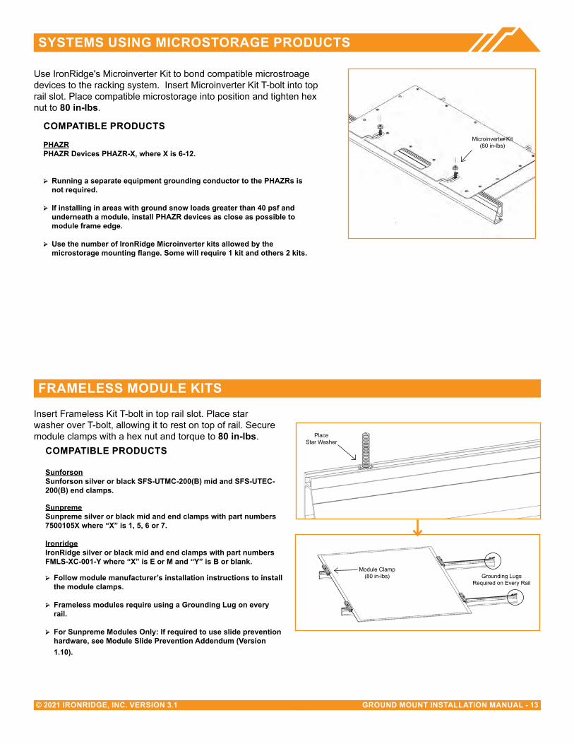
Use IronRidge's Microinverter Kit to bond compatible microstroage devices to the racking system. Insert Microinverter Kit T-bolt into top rail slot. Place compatible microstorage into position and tighten hex nut to 80 in-lbs.
Microinverter Kit(80 in-lbs)
SYSTeMS USING MICROSTORAGe PRODUCTS
Insert Frameless Kit T-bolt in top rail slot. Place star washer over T-bolt, allowing it to rest on top of rail. Secure module clamps with a hex nut and torque to 80 in-lbs. Place
Star Washer
Module Clamp(80 in-lbs) Grounding Lugs
Required on Every Rail
FRAMeLeSS MODULe KITS
COMPATIBLe PRODUCTS
PHAZR PHAZR Devices PHAZR-X, where X is 6-12.
➢ Running a separate equipment grounding conductor to the PHAZRs is not required.
➢ If installing in areas with ground snow loads greater than 40 psf and underneath a module, install PHAZR devices as close as possible to module frame edge.
➢ Use the number of IronRidge Microinverter kits allowed by the microstorage mounting flange. Some will require 1 kit and others 2 kits.
COMPATIBLe PRODUCTS
SunforsonSunforson silver or black SFS-UTMC-200(B) mid and SFS-UTEC-200(B) end clamps.
SunpremeSunpreme silver or black mid and end clamps with part numbers 7500105X where “X” is 1, 5, 6 or 7.
IronridgeIronRidge silver or black mid and end clamps with part numbers FMLS-XC-001-Y where “X” is E or M and “Y” is B or blank.
➢ Follow module manufacturer’s installation instructions to installthe module clamps.
➢ Frameless modules require using a Grounding Lug on every rail.
➢ For Sunpreme Modules Only: If required to use slide prevention hardware, see Module Slide Prevention Addendum (Version 1.10).
GROUND MOUNT INSTALLATION MANUAL - 14© 2021 IRONRIDGE, INC. VERSION 3.1
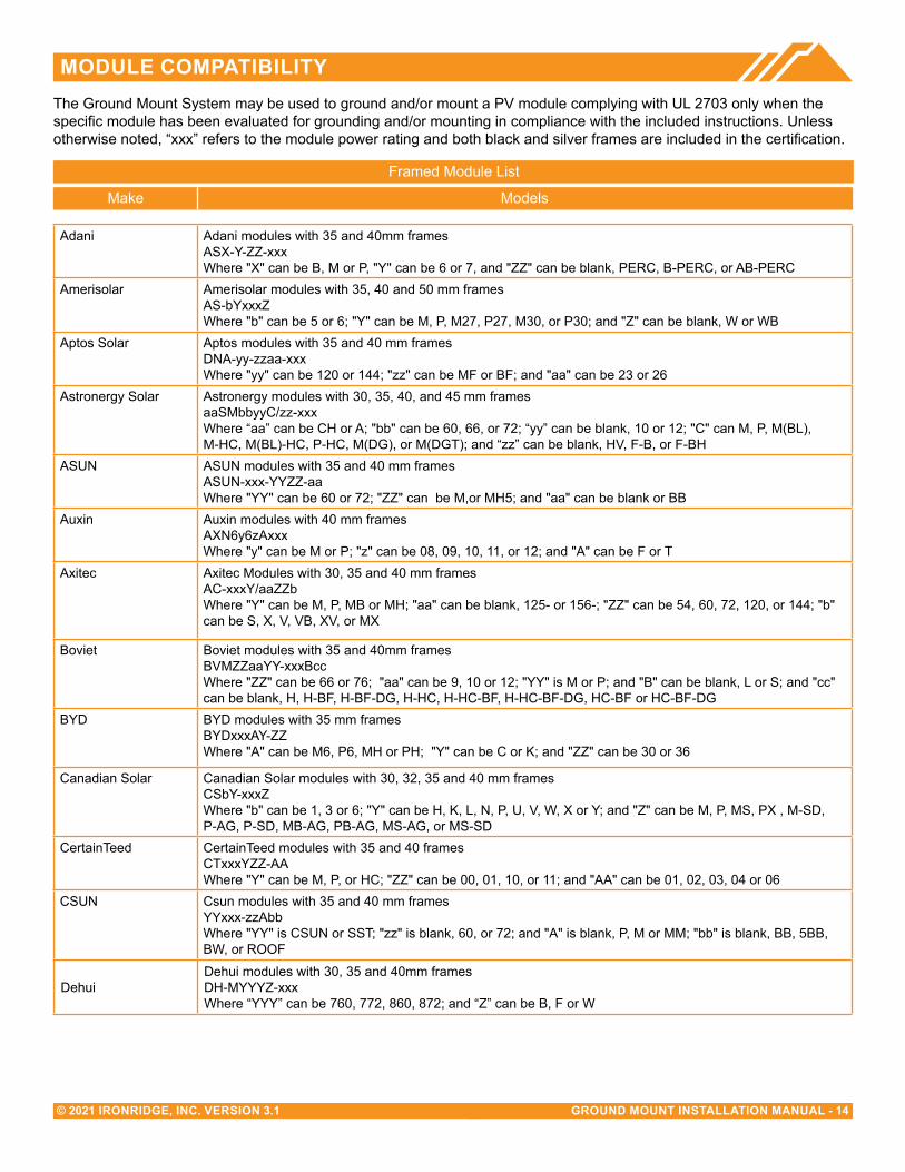
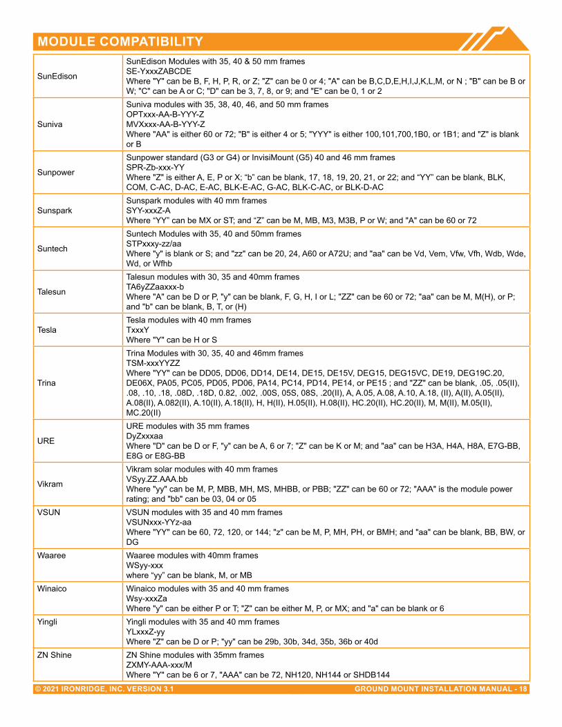
MODULe COMPATIBILITYThe Ground Mount System may be used to ground and/or mount a PV module complying with UL 2703 only when the specific module has been evaluated for grounding and/or mounting in compliance with the included instructions. Unless otherwise noted, “xxx” refers to the module power rating and both black and silver frames are included in the certification.
Make Models
Framed Module List
Adani Adani modules with 35 and 40mm framesASX-Y-ZZ-xxxWhere "X" can be B, M or P, "Y" can be 6 or 7, and "ZZ" can be blank, PERC, B-PERC, or AB-PERC
Amerisolar Amerisolar modules with 35, 40 and 50 mm frames AS-bYxxxZ Where "b" can be 5 or 6; "Y" can be M, P, M27, P27, M30, or P30; and "Z" can be blank, W or WB
Aptos Solar Aptos modules with 35 and 40 mm framesDNA-yy-zzaa-xxxWhere "yy" can be 120 or 144; "zz" can be MF or BF; and "aa" can be 23 or 26
Astronergy Solar Astronergy modules with 30, 35, 40, and 45 mm frames aaSMbbyyC/zz-xxx Where “aa” can be CH or A; "bb" can be 60, 66, or 72; “yy” can be blank, 10 or 12; "C" can M, P, M(BL), M-HC, M(BL)-HC, P-HC, M(DG), or M(DGT); and “zz” can be blank, HV, F-B, or F-BH
ASUN ASUN modules with 35 and 40 mm frames ASUN-xxx-YYZZ-aa Where "YY" can be 60 or 72; "ZZ" can be M,or MH5; and "aa" can be blank or BB
Auxin Auxin modules with 40 mm frames AXN6y6zAxxx Where "y" can be M or P; "z" can be 08, 09, 10, 11, or 12; and "A" can be F or T
Axitec Axitec Modules with 30, 35 and 40 mm frames AC-xxxY/aaZZbWhere "Y" can be M, P, MB or MH; "aa" can be blank, 125- or 156-; "ZZ" can be 54, 60, 72, 120, or 144; "b" can be S, X, V, VB, XV, or MX
Boviet Boviet modules with 35 and 40mm framesBVMZZaaYY-xxxBccWhere "ZZ" can be 66 or 76; "aa" can be 9, 10 or 12; "YY" is M or P; and "B" can be blank, L or S; and "cc" can be blank, H, H-BF, H-BF-DG, H-HC, H-HC-BF, H-HC-BF-DG, HC-BF or HC-BF-DG
BYD BYD modules with 35 mm frames BYDxxxAY-ZZ Where "A" can be M6, P6, MH or PH; "Y" can be C or K; and "ZZ" can be 30 or 36
Canadian Solar Canadian Solar modules with 30, 32, 35 and 40 mm framesCSbY-xxxZWhere "b" can be 1, 3 or 6; "Y" can be H, K, L, N, P, U, V, W, X or Y; and "Z" can be M, P, MS, PX , M-SD, P-AG, P-SD, MB-AG, PB-AG, MS-AG, or MS-SD
CertainTeed CertainTeed modules with 35 and 40 framesCTxxxYZZ-AAWhere "Y" can be M, P, or HC; "ZZ" can be 00, 01, 10, or 11; and "AA" can be 01, 02, 03, 04 or 06
CSUN Csun modules with 35 and 40 mm framesYYxxx-zzAbbWhere "YY" is CSUN or SST; "zz" is blank, 60, or 72; and "A" is blank, P, M or MM; "bb" is blank, BB, 5BB, BW, or ROOF
DehuiDehui modules with 30, 35 and 40mm framesDH-MYYYZ-xxxWhere “YYY” can be 760, 772, 860, 872; and “Z” can be B, F or W

GROUND MOUNT INSTALLATION MANUAL - 15© 2021 IRONRIDGE, INC. VERSION 3.1
MODULe COMPATIBILITY
Ecosolargy
Ecosolargy modules with 35, 40, and 50 mm framesECOxxxYzzA-bbDWhere “Y” can be A, H, S, or T; “zz” can be 125 or 156; “A” can be M or P; “bb” can be 60 or 72; and “D” can be blank or B
ET Solar
ET Solar modules with 30, 35, 40, and 50 mm frames ET-YZZZxxxAA Where "Y" can be P, L, or M; "ZZZ" can be 660, 660BH, 672, 672BH, 754BH, 766BH, 772BH; and "AA" can be GL, TB, TW, WB, WW, BB, WBG, WWG, WBAC, WBCO, WWCO, WWBCO or BBAC
Flex
Flex modules with 35, 40, and 50 mm frames FXS-xxxYY-ZZ; Where “YY” can be BB or BC; and “ZZ” can be MAA1B, MAA1W, MAB1W, SAA1B, SAA1W, SAC1B, SAC1W, SAD1W, SBA1B, SBA1W, SBC1B, or SBC1W
GCLGCL modules with 35 mm and 40 mm frames GCL-ab/YY xxx Where “a” can be M or P; “b” can be 3 or 6; and “YY” can be 60, 72, 72H, or 72DH
GigaWatt SolarGigawatt modules with 40 mm frames GWxxxYY Where “YY” can be either PB or MB
Hansol
Hansol modules with 35 and 40 framesHSxxxYY-zzWhere “YY” can be PB, PD, PE, TB, TD, UB, UD, or UE; and “zz” can be AH2, AN1, AN3, AN4, HH2, HV1, or JH2
Hanwa SolarHanwha Solar modules with 40, 45, and 50 mm frames HSLaaP6-YY-1-xxxZ Where “aa” can be either 60 or 72; “YY” can be PA or PB; and “Z” can be blank or B
Hanwha Q CELL
Hanwha Q CELLS Modules with 32, 35, 40, and 42mm framesaaYY-ZZ-xxxwhere "aa" can be Q. or B.; "YY" can be PLUS, PRO, PEAK, LINE PRO, LINE PLUS, PLUS DUO or PEAK DUO; and "ZZ" can be G3, G3.1, G4, G4.1, L-G2, L-G2.3, L-G3, L-G3.1, L-G3y, L-G4, L-G4.2, L-G4y, LG4.2/TAA, BFR-G3, BLK-G3, BFR-G3.1, BLK-G3.1, BFR-G4, BFR-G4.1, BFR G4.3, BLK-G4.1, G4/SC, G4.1/SC, G4.1/TAA, G4.1/MAX, BFR G4.1/TAA, BFR G4.1/MAX, BLK G4.1/TAA, BLK G4.1/SC, EC-G4.4, G5, G5/SC, G5/TS, BLK-G5, BLK-G5/SC, BLK-G5/TS, L-G5, L-G5.1, L-G5.2, L-G5.2/H, L-G5.3, G6, G6/SC, G6/TS, G6+/TS, G6+, BLK-G6, L-G6, L-G6.1, L-G6.2, L-G6.3, G7, BLK-G6+, BLK-G6+/AC, BLK-G6+/HL, BLK-G6+/SC, BLK-G6/TS, BLK-G6+/TS, BLK-G7, G7.2, G8, BLK-G8, G8+, BLK-G8+ L-G7, L-G7.1, L-G7.2, L-G7.3, L-G8, L-G8.1, L-G8.2, L-G8.3, L-G8.3/BFF, L-G8.3/BFG, L-G8.3/BGT, ML-G9, BLK ML-G9, ML-G9+, BLK ML-G9+, ML-G10, BLK ML-G10, ML-G10+, BLK ML-G10+, ML-G10.a, BLK ML-G10.a, ML-G10.a+, BLK ML-G10.a+, XL-G9, XL-G9.2, XL-G9.3, XL-G9.3/BFG, XL-G10.2, XL-G10.3, XL-G10.c, XL-G10.d, XL-G10.d/BFG or XL-G10.3/BFG
Heliene
Heliene modules with 40 mm framesYYZZxxxAWhere "YY" can be 36, 60, 72, 96, 120 or 144; "ZZ" can be HC, M, P, or MBLK; and "A" can be blank, Home-PV, or Bifacial
HT-SAAE
HT-SAAE modules with 35 and 40 mm framesHTyy-aaaZ-xxxWhere "yy" can be 60, 66, 72 or 78, "aaa" can be 18, 156 or 166, "Z" can be M, P, M-C, P-C, M(S), M(VS), M(V), P(V), M(V)-C, P(V)-C, or X
Hyundai Hyundai modules with 33, 35, 40 and 50 mm framesHiY-SxxxZZWhere "Y" can be A, D or S; "S" can be M or S; and "ZZ" can be GI, HG, HI, KI, MI, MF, MG, PI, RI, RG, RG(BF), RG(BK), SG, TI or TG
ItekItek Modules with 40 and 50 mm frames IT-xxx-YY Where “YY” can be blank, HE, or SE, or SE72
GROUND MOUNT INSTALLATION MANUAL - 16© 2021 IRONRIDGE, INC. VERSION 3.1
MODULe COMPATIBILITY
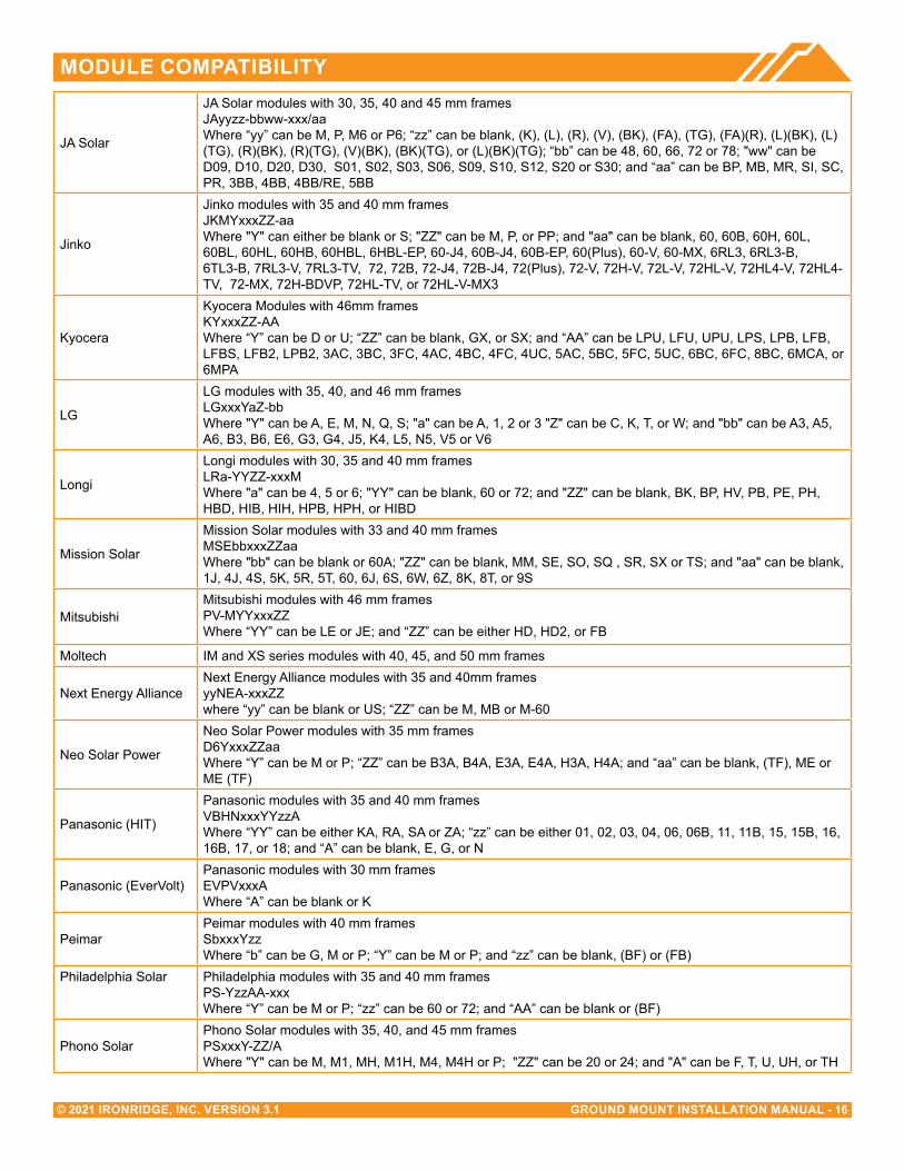
JA Solar
JA Solar modules with 30, 35, 40 and 45 mm framesJAyyzz-bbww-xxx/aaWhere “yy” can be M, P, M6 or P6; “zz” can be blank, (K), (L), (R), (V), (BK), (FA), (TG), (FA)(R), (L)(BK), (L)(TG), (R)(BK), (R)(TG), (V)(BK), (BK)(TG), or (L)(BK)(TG); “bb” can be 48, 60, 66, 72 or 78; "ww" can be D09, D10, D20, D30, S01, S02, S03, S06, S09, S10, S12, S20 or S30; and “aa” can be BP, MB, MR, SI, SC, PR, 3BB, 4BB, 4BB/RE, 5BB
Jinko
Jinko modules with 35 and 40 mm framesJKMYxxxZZ-aaWhere "Y" can either be blank or S; "ZZ" can be M, P, or PP; and "aa" can be blank, 60, 60B, 60H, 60L, 60BL, 60HL, 60HB, 60HBL, 6HBL-EP, 60-J4, 60B-J4, 60B-EP, 60(Plus), 60-V, 60-MX, 6RL3, 6RL3-B, 6TL3-B, 7RL3-V, 7RL3-TV, 72, 72B, 72-J4, 72B-J4, 72(Plus), 72-V, 72H-V, 72L-V, 72HL-V, 72HL4-V, 72HL4-TV, 72-MX, 72H-BDVP, 72HL-TV, or 72HL-V-MX3
Kyocera
Kyocera Modules with 46mm frames KYxxxZZ-AA Where “Y” can be D or U; “ZZ” can be blank, GX, or SX; and “AA” can be LPU, LFU, UPU, LPS, LPB, LFB, LFBS, LFB2, LPB2, 3AC, 3BC, 3FC, 4AC, 4BC, 4FC, 4UC, 5AC, 5BC, 5FC, 5UC, 6BC, 6FC, 8BC, 6MCA, or 6MPA
LG
LG modules with 35, 40, and 46 mm framesLGxxxYaZ-bbWhere "Y" can be A, E, M, N, Q, S; "a" can be A, 1, 2 or 3 "Z" can be C, K, T, or W; and "bb" can be A3, A5, A6, B3, B6, E6, G3, G4, J5, K4, L5, N5, V5 or V6
Longi
Longi modules with 30, 35 and 40 mm framesLRa-YYZZ-xxxMWhere "a" can be 4, 5 or 6; "YY" can be blank, 60 or 72; and "ZZ" can be blank, BK, BP, HV, PB, PE, PH, HBD, HIB, HIH, HPB, HPH, or HIBD
Mission Solar
Mission Solar modules with 33 and 40 mm framesMSEbbxxxZZaaWhere "bb" can be blank or 60A; "ZZ" can be blank, MM, SE, SO, SQ , SR, SX or TS; and "aa" can be blank, 1J, 4J, 4S, 5K, 5R, 5T, 60, 6J, 6S, 6W, 6Z, 8K, 8T, or 9S
MitsubishiMitsubishi modules with 46 mm frames PV-MYYxxxZZ Where “YY” can be LE or JE; and “ZZ” can be either HD, HD2, or FB
Moltech IM and XS series modules with 40, 45, and 50 mm frames
Next Energy AllianceNext Energy Alliance modules with 35 and 40mm framesyyNEA-xxxZZwhere “yy” can be blank or US; “ZZ” can be M, MB or M-60
Neo Solar Power
Neo Solar Power modules with 35 mm frames D6YxxxZZaa Where “Y” can be M or P; “ZZ” can be B3A, B4A, E3A, E4A, H3A, H4A; and “aa” can be blank, (TF), ME or ME (TF)
Panasonic (HIT)
Panasonic modules with 35 and 40 mm frames VBHNxxxYYzzA Where “YY” can be either KA, RA, SA or ZA; “zz” can be either 01, 02, 03, 04, 06, 06B, 11, 11B, 15, 15B, 16, 16B, 17, or 18; and “A” can be blank, E, G, or N
Panasonic (EverVolt)Panasonic modules with 30 mm framesEVPVxxxAWhere “A” can be blank or K
PeimarPeimar modules with 40 mm frames SbxxxYzz Where “b” can be G, M or P; “Y” can be M or P; and “zz” can be blank, (BF) or (FB)
Philadelphia Solar Philadelphia modules with 35 and 40 mm frames PS-YzzAA-xxx Where “Y” can be M or P; “zz” can be 60 or 72; and “AA” can be blank or (BF)
Phono SolarPhono Solar modules with 35, 40, and 45 mm framesPSxxxY-ZZ/AWhere "Y" can be M, M1, MH, M1H, M4, M4H or P; "ZZ" can be 20 or 24; and "A" can be F, T, U, UH, or TH

MODULe COMPATIBILITY
GROUND MOUNT INSTALLATION MANUAL - 17© 2021 IRONRIDGE, INC. VERSION 3.1
RecomRecom modules with 35 and 40 mm framesRCM-xxx-6yyWhere “yy” can be MA, MB, ME or MF
REC Solar
REC modules with 30, 38 and 45 mm framesRECxxxYYZZWhere “YY” can be AA, M, NP, NP2, PE, PE72, TP, TP2, TP2M, TP2SM, TP2S, TP3M or TP4; and “ZZ” can be blank, Black, BLK, BLK2, SLV, 72, or Pure
Renesola
ReneSola modules with 35, 40 and 50 mm frames AAxxxY-ZZ Where "AA" can be SPM(SLP) or JC; "Y" can be blank, F, M or S; and "ZZ" can be blank, Ab, Ab-b, Abh, Abh-b, Abv, Abv-b, Bb, Bb-b, Bbh, Bbh-b, Bbv, Bbv-b, Db, Db-b, or 24/Bb
RenogyRenogy Modules with 40 and 50 mm frames RNG-xxxY Where “xxx” is the module power rating; and “Y” can be D or P
RisenRisen Modules with 30, 35 and 40 mm framesRSMyy-a-xxxZZWhere "yy" can be 60, 72, 110, 120, 132 or 144; "a" can be 6, 7 or 8; and "ZZ" can be M, P or BMDG
S-Energy
S-Energy modules with 35 and 40mm framesSABB-CCYYY-xxxZWhere “A” can be C, D, L or N; “BB” can be blank, 20, 25, 40 or 45; “CC” can be blank, 60 or 72; “YYY” can be blank, BDE, MAE, MAI, MBE, MBI, MCE or MCI; and “Z” can be V, M-10, P-10 or P-15
Seraphim Energy Group
Seraphim modules with 30, 35 and 40 mm framesSEG-aYY-xxxZZWhere “a” can be blank, 6 or B; “YY” can be blank, MA, MB, PA, or PB; and “ZZ” can be blank, BB, BG, BW, HV, WB, WW, BMB, BMA-HV, BMA-BG, BMB-HV
Seraphim USA
Seraphim modules with 30, 35, 40 and 50 mm framesSRP-xxx-YYY-ZZWhere "xxx" is the module power rating; and "YYY" can be BMA, BMD, 6MA, 6MB, 6PA, 6PB, 6QA-XX-XX, and 6QB-XX-XX; ZZ is blank, BB, BG or HV
SharpSharp modules with 35 and 40 mm framesNUYYxxxWhere “YY” can be SA or SC
Silfab
Silfab Modules with 35 and 38 mm framesSYY-Z-xxxAbWhere "YY" can be IL, SA, LA, SG or LG; "Z" can be blank, M, P, or X; "A" can be blank, B, H, M, N; and "b" can be A, C, L, G, K, T, U or X
SolariaSolaria modules with 40 mm frames PowerXT xxxY-ZZ Where “Y” can be R or C; and “ZZ” can be AC, BD, BX, BY, PD, PM, PM-AC, PX, PZ, WX or WZ
Solarcity (Tesla)Solarcity modules with 40 mm frames SCxxxYY Where “YY” can be blank, B1 or B2
SolarTechSolarTech modules with 40 and 42 mm framesAAA-xxxYYWhere "AAA" can be PERCB-B, PERCB-W, HJTB-B, HJTB-W or STU; "YY" can be blank, PERC or HJT
SolarWorld AGSolarWorld Sunmodule Plus, Protect, Bisun, XL, Bisun XL, may be followed by mono, poly, duo, black, bk, or clear; modules with 31, 33 or 46 mm frames SW-xxx
SolarWorld AmericasSolarWorld Sunmodule Plus, Protect, Bisun, XL, Bisun XL, may be followed by mono, poly, duo, black, bk, or clear; modules with 33 mm frames SWA-xxx
Sonali Sonali Modules with 40 mm framesSSxxx
Stion Stion Thin film modules with 35 mm frames STO-xxx or STO-xxxA
MODULe COMPATIBILITY
GROUND MOUNT INSTALLATION MANUAL - 18© 2021 IRONRIDGE, INC. VERSION 3.1
SunEdison
SunEdison Modules with 35, 40 & 50 mm frames SE-YxxxZABCDE Where "Y" can be B, F, H, P, R, or Z; "Z" can be 0 or 4; "A" can be B,C,D,E,H,I,J,K,L,M, or N ; "B" can be B or W; "C" can be A or C; "D" can be 3, 7, 8, or 9; and "E" can be 0, 1 or 2
Suniva
Suniva modules with 35, 38, 40, 46, and 50 mm frames OPTxxx-AA-B-YYY-Z MVXxxx-AA-B-YYY-Z Where "AA" is either 60 or 72; "B" is either 4 or 5; "YYY" is either 100,101,700,1B0, or 1B1; and "Z" is blank or B
Sunpower
Sunpower standard (G3 or G4) or InvisiMount (G5) 40 and 46 mm framesSPR-Zb-xxx-YYWhere "Z" is either A, E, P or X; “b” can be blank, 17, 18, 19, 20, 21, or 22; and “YY” can be blank, BLK, COM, C-AC, D-AC, E-AC, BLK-E-AC, G-AC, BLK-C-AC, or BLK-D-AC
SunsparkSunspark modules with 40 mm framesSYY-xxxZ-AWhere “YY” can be MX or ST; and “Z” can be M, MB, M3, M3B, P or W; and "A" can be 60 or 72
Suntech
Suntech Modules with 35, 40 and 50mm framesSTPxxxy-zz/aaWhere "y" is blank or S; and "zz" can be 20, 24, A60 or A72U; and "aa" can be Vd, Vem, Vfw, Vfh, Wdb, Wde, Wd, or Wfhb
Talesun
Talesun modules with 30, 35 and 40mm framesTA6yZZaaxxx-bWhere "A" can be D or P, "y" can be blank, F, G, H, I or L; "ZZ" can be 60 or 72; "aa" can be M, M(H), or P; and "b" can be blank, B, T, or (H)
TeslaTesla modules with 40 mm framesTxxxYWhere "Y" can be H or S
Trina
Trina Modules with 30, 35, 40 and 46mm framesTSM-xxxYYZZWhere "YY" can be DD05, DD06, DD14, DE14, DE15, DE15V, DEG15, DEG15VC, DE19, DEG19C.20, DE06X, PA05, PC05, PD05, PD06, PA14, PC14, PD14, PE14, or PE15 ; and "ZZ" can be blank, .05, .05(II), .08, .10, .18, .08D, .18D, 0.82, .002, .00S, 05S, 08S, .20(II), A, A.05, A.08, A.10, A.18, (II), A(II), A.05(II), A.08(II), A.082(II), A.10(II), A.18(II), H, H(II), H.05(II), H.08(II), HC.20(II), HC.20(II), M, M(II), M.05(II), MC.20(II)
URE
URE modules with 35 mm framesDyZxxxaaWhere "D" can be D or F, "y" can be A, 6 or 7; "Z" can be K or M; and "aa" can be H3A, H4A, H8A, E7G-BB, E8G or E8G-BB
Vikram
Vikram solar modules with 40 mm frames VSyy.ZZ.AAA.bb Where "yy" can be M, P, MBB, MH, MS, MHBB, or PBB; "ZZ" can be 60 or 72; "AAA" is the module power rating; and "bb" can be 03, 04 or 05
VSUN VSUN modules with 35 and 40 mm framesVSUNxxx-YYz-aaWhere "YY" can be 60, 72, 120, or 144; "z" can be M, P, MH, PH, or BMH; and "aa" can be blank, BB, BW, or DG
Waaree Waaree modules with 40mm framesWSyy-xxxwhere “yy” can be blank, M, or MB
Winaico Winaico modules with 35 and 40 mm frames Wsy-xxxZa Where "y" can be either P or T; "Z" can be either M, P, or MX; and "a" can be blank or 6
Yingli Yingli modules with 35 and 40 mm framesYLxxxZ-yyWhere "Z" can be D or P; "yy" can be 29b, 30b, 34d, 35b, 36b or 40d
ZN Shine ZN Shine modules with 35mm framesZXMY-AAA-xxx/MWhere "Y" can be 6 or 7, "AAA" can be 72, NH120, NH144 or SHDB144
MODULe COMPATIBILITY
GROUND MOUNT INSTALLATION MANUAL - 19© 2021 IRONRIDGE, INC. VERSION 3.1
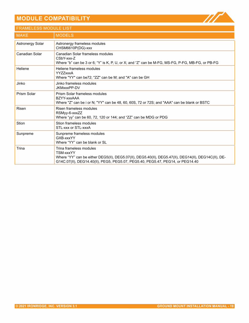
MAKE MODELS
FRAMELESS MODULE LIST
Astronergy Solar Astronergy frameless modules CHSM6610P(DG)-xxx
Canadian Solar Canadian Solar frameless modules CSbY-xxx-Z Where “b” can be 3 or 6; “Y” is K, P, U, or X; and “Z” can be M-FG, MS-FG, P-FG, MB-FG, or PB-FG
Heliene Heliene frameless modulesYYZZxxxAWhere "YY" can be72; "ZZ" can be M; and "A" can be GH
Jinko Jinko frameless modules JKMxxxPP-DV
Prism Solar Prism Solar frameless modulesBZYY-xxxAAAWhere "Z" can be i or N; "YY" can be 48, 60, 60S, 72 or 72S; and "AAA" can be blank or BSTC
Risen Risen frameless modules RSMyy-6-xxxZZ Where “yy” can be 60, 72, 120 or 144; and “ZZ” can be MDG or PDG
Stion Stion frameless modules STL-xxx or STL-xxxA
Sunpreme Sunpreme frameless modules GXB-xxxYY Where “YY” can be blank or SL
Trina Trina frameless modules TSM-xxxYY Where “YY” can be either DEG5(II), DEG5.07(II), DEG5.40(II), DEG5.47(II), DEG14(II), DEG14C(II), DE-G14C.07(II), DEG14.40(II), PEG5, PEG5.07, PEG5.40, PEG5.47, PEG14, or PEG14.40