irrigation & cad department government of andhra pradesh final/qc... · government of andhra...
TRANSCRIPT

1
ANDHRA PRADESH WATER SECTOR
IMPROVEMENT PROJECT
PROJECT IMPLEMENTATION PLAN
VOLUME VIII
QUALITY CONTROL AND QUALITY ASSURANCE
MANUAL
PROJECT PREPARATION AND MANAGEMENT UNIT
JANUARY 2010
IRRIGATION & CAD DEPARTMENT
GOVERNMENT OF ANDHRA PRADESH

2
INDEX
LIST OF INDIAN STANDARDS i-iii
1. CHAPTER 1 QUALITY ASSURANCE AND CONTROL 1-3
2. CHAPTER II ORGANISATIONAL SET-UP 4-5
3. CHAPTER III FUNCTIONS OF CENTRAL LABORATORY 6-10
4. CHAPTER IV DUTIES OF DEPUTY EXECUTIVE
ENGINEER & OTHERS INCHARGE OF
LABORATORY. 11-13
5. CHAPTER V DUTIES OF FIELD STAFF IN RELATION
TO QUALITY CONTROL 14-17
6. CHAPTER VI CO-ORDINATIONS 18-19
7. CHAPTER VII QUALITY ASSURANCE 20-22
8. CHAPTER VIII MONITORING THROUGH CONTROL
CHARTS 23-28
9. CHAPTER IX O.K. CARDS 29-36
10. CHAPTER X TESTS TO BE PERFORMED ON MATERIALS 37-38
11. CHAPTER XI LIST OF EQUIPMENT FOR CEMENT
AND CONCRETE TESTING 39-40
12. CHAPTER XII FORMATS OF TEST RESULTS 41-55
13. CHAPTER XIII IMPORTANT SPECIFICATIONS 56-79
14. CHAPTER XIV FREQUENCY OF TESTING 80-81
15. CHAPTER XV COMPILATION OF QUALITY
CONTROL DATA 82
16. CHAPTER XVI PROCEDURE FOR EXECUTING
EARTHWORK 83-86

3
17. CHAPTER XVII PROCEDURE FOR EXECUTING
CONCRETE LINING 87-90
18. CHAPTER XVIII PROCEDURE FOR EXECUTING
R.C.C. WORK & CONCRETE FOR
STRUCTURES 91-94
19. CHAPTER XIX PROCEDURE FOR SHOT-CRETING
AND GUNTING 95-99
20. ANNEXURE I SKETCH SHOWING THE ROLE
& RESPONSIBILITY MATRIX 100-101
21. ANNEXURE II SCOPE AND INSPECTION OF
TESTING ACTIVITIES 102
22. ANNEXURE III CORRECTION FACTOR FOR
HEIGHT BY DIAMETER RATIO
OF A CORE 103
23. ANNWXURE IV ILLUSTRATION OF PREPARATION OF
CONTROL CHARTS FOR CEMENT AND
CONCRETE 104-117
24. ANNEXURE V SKETCH SHOWING CONSTRUCTION
JOINTS IN LINING 118
25. ANNEXURE VI SKETCH SHOWING AIR – WATER GUN 119
26. ANNEXURE VII(a) ILLUSTRATIVE SKETCH SHOWING
COMPACTION OF C.N.S. SOIL IN
DISTRIBUTORIES 120
27. ANNEXURE VII(b) ILLUSTRATIVE SKETCH SHOWING
TREATMENT OF CANAL PRISM IN
EXPANSIVE SOILS WITH CNS MATERIALS 121
28. ANNEXURE VIII CURVE SHOWING RELATION BETWEEN
SPECIMEN SIZE AND STRENGTH
OF CONCRETE CORE 122
29. ANNEXURE IX DATA OF THE CORES TAKEN FROM IN-
SITU CONCRETE CANAL LINING. 123
30. ANNEXURE X STATEMENT SHOWING CAPACITY OF
PAVER AND MECHANICAL TRIMMER 124

4
31. PHOTOS
i. One meter wide Vibratory Roller being used for 125
Earth fill Compaction
ii. Acrow Gantry 126
iii. Level Compactor 127
iv. Portable Electronic Devices for Quick on-site
measurement of moisture content, in place
density & compaction of sub-grade/embankment 128
v. 1 H.P. Engine (Petrol/Kerosene Driven)
Fuel-operated plate vibrator for consolidation of
CC lining on canal slope 129
vi. Compaction of Sub-grade on Canal side slope
with Fuel-Operated portable Compactor 130
vii. Slip Form Steel Gantry fitted with Vibrators For
Placement of Cement Concrete lining on side
slopes (single rail track) 131
viii. Mobile Self-loading, Weigh batching and
Mixing as well as transporting concrete Mixer
(viz. mobile B & M Plant) 132
ix. Fuel-operated plate vibrator for consolidation of
CC lining on canal slope 133
x. Steel shutter Gantry for Placement of CC Lining
on sides 134
xi. Acrow type shuttering for canal lining 135
xii. Planning and Design of Revetment- Guidelines 137
xiii. Sketch showing Typical Porous Plug for
Under-Drainage Arrangement for Lining 138
xiv. Pressure relief hole and laying concrete in panels 139

5
xv. Relationship between free water-cement ratio and
28-days compressive strength of concrete 140
xvi. Relationship between Free water-cement ratio and
concrete strength for different cement strengths 141
CHAPTER – 1
QUALITY ASSURANCE AND CONTROL
1. INTRODUCTION:
Execution of multipurpose river projects involves enormous expenditure. They
are time bound programme and require assistance from various technical bodies for
investigation, design, planning and execution. To have a safe durable structure, it is
necessary that the materials and Standard of execution fully satisfy the specifications.
It is to be recognized that while the ultimate efficiency of the performance of a
project will depend upon proper layout and designs, the ultimate health of the project
during life scale of its operational phase will depend largely on the quality achieved
during its construction.
This can be realized through stringent quality control measures jointly by the team
members comprising of G.O.A.P., Contractor, Project Construction Team, Project Q.C
/Q.A Team and Project Design Team. The pursuit of quality shall be the cement holding
these members together in a stable pattern where each supports the other in producing a
successful project executed to acceptable quality control standards.
2. OBJECTIVES AND SCOPE OF QUALITY CONTROL:
The objective of quality control management is to collect process and then
communicate the data related to the quality of inputs and outputs as well as finished item
of work to those who are responsible for the quality. Any programme of quality control
seeks adequacy and uniformity of quality through the following operations.
1. Inspection of storage, handling and processing facilities for all materials in
conformity with accepted or specified practice.
2. Monitoring the variation in specification of the materials and quantities used
in the operation of production and in the final product by suitable observation,
measurements or tests.

6
3. In order to achieve the common goal – Construction quality in the execution
of project, the roles and responsibility matrix, as depicted in Annexure I shall
be broadly followed by
i. G.O.A.P.
ii. Contractor
iii. Project Construction Team
iv. Project QC / QA Team and
v. Project Design Team
4. Analysis of the observed variations by statistical or other techniques.
5. Feed-back of the results of analysis for exercise of control at each stage and to
take corrective steps for maintaining the variations within specified limits.
6. Indicating expeditiously the possible remedial measures, if specifications are
not likely to be met.
7. Rejecting, where warranted, the material or the product at any intermediate or
final stage in case acceptance criteria is not satisfied.
3) QUALITY CONTROL MANUAL:
It is a very important constituent of the quality management system. It is a
document encompassing specific requirement which if fulfilled, shall help in effectively
implementing the quality control system to achieve the objective of good construction
quality. It covers broadly; the objectives, functions and operations of the Q.C.
Organization; duties and responsibilities of Q.C. personnel; Q.C. Organization; Q.C.
Laboratory System; O.K. Cards; Monitoring through Control Charts; Control on
workmanship; Tests on materials; Important specifications; Quality Audit and Quality
Improvement; Standards to be adopted for materials and works; Frequency of testing and
reporting; Compilation of Q.C. Data and Statistical Analysis etc; Documentation and
Feed-back; Inspection etc.
4. Configuration of Quality Management System
QUALITY MANAGEMENT SYSTEM
Quality Planning, Quality Control Quality Assurance
Q.C. Manual:
Training of Q.C /Q.A
Staff, Infrastructure

7
etc.,
Testing of inputs/outputs
OK card system
QUALITY CONTROL (Q.C.):
The operational techniques and activities that are used to fulfill the requirements
for quality.
5.1 QUALITY ASSURANCE (Q.A.):
All the planned and systematic activities implemented within the quality system
and demonstrated as needed to provide adequate confidence that an entity will
fulfill requirements for quality and making sure that the quality of a product is
what it should be.
Purpose of Quality Assurance is to prevent problems before they occur, to
identify and correct them swiftly if they occur and to uncover the root cause.
5.2 QUALITY MANAGEMENT:
All activities of the overall management function that determine the quality
policy, objectives & responsibilities and implement them by means such as
Quality Planning, Quality Control, Quality Assurance, and Quality Improvement
within the quality system.
THE QUALITY CONTROL MANUAL being adopted for APWSIP (the salient
requirements of which are being outlined in the various Chapters) aims at a
“Systems Approach” to ensure that upon implementation, the quality levels as set
and defined in the specifications and contract documents and relevant Indian
Standards would be met in the execution of project works.
**********

8
CHAPTER – II
ORGANISATIONAL SETUP
GENERAL:
Any one connected with quality control work, should possess adequate knowledge and
experience of quality control works and be conversant with general testing of
construction materials. The object of Quality control should be clearly understood by
them in letter and spirit so as to help in construction and achieve high order of quality as
laid down in specifications for works by controlling various factors responsible for
deterioration in quality, investigating reasons therefore and suggesting ways and means
for improvement and not to hinder the progress.
Quality Control Organization:
The existing Quality Control Organization under the Chief Engineer, Nagarjunasagar
Project comprising 2 divisions being deficient in staffing, Quality Control testing laboratories
and the testing equipment, would be appropriately strengthened by GoAP by induction of
additional quality control staff and augmentation of materials testing facilities including
procurement of needed laboratory equipment. Provision of Rs. 9 million has been made for
procurement of new quality control testing equipment in the project cost estimate. In respect
of quality control personnel, GoAP has already taken action to add one circle headed by
Superintending Engineer and one more quality control division with the associative staff,
four Deputy Executive Engineers and 16 Assistant Engineers/Assistant Executive Engineers
(through re-deployment) to strengthen the existing setup of quality control wing the proposal
quality control chart is appended in the Attachment – 1

9
Attachment - I
Chief Engineer, NS Project
SE, QC &QA
Circle, Nuzvid
Jawahar
Canal (Right)
Lal
bahadur Canal(Left)
E.E QC Division,
Mylavaram
E.E QC Division, Nuzvid
QC sub Division,
1.Mylavaram
QC sub Division,
2.Mylavaram
QC sub Division,
3.Mylavaram
QC sub Division,
4.Mylavaram
QC sub Division, Nuzvid
QC sub Division, Musunuru
QC sub Division, Vatluru
QC sub Division, Vijayawada
E.E QC Division,
Vinukonda
QC sub division,
1.Vinukonda
QC sub sivision,
2.Vinukonda
QC sub division, Kurichedu
QC sub division,
Tripuranthakam
QC sub division, Guntur
L&T sub division,
Lingamguntla

10
CHAPTER – III
GENERAL FUNCTIONS OF LABORATORIES
The Laboratory system in addition to evaluate and monitor the inputs and outputs would also evaluate
and monitor the workmanship as well as construction plant, machinery and equipment. This would, thus, be
accompanied by testing as well as inspection.
FUNCTIONS OF CENTRAL LABORATORY SYSTEM
I To conduct laboratory tests on samples of sand, coarse aggregate, stone, cement and steel for use
in masonry and concrete works.
II To conduct laboratory tests for foundation soil and for selection of soils from proposed borrow
areas for use in the various zones of embankment as per specifications.
III For masonry and concrete, the strength of mortar and concrete has to be as specified in agreement.
Laboratory has to design the proportions of different ingredients through tests for the specified
strength. The proportioning shall be done by weight.
IV For Concrete and mortars where strength is not given and only proportions have been specified,
the strength should be treated as standard for execution.
V When controlled concrete is specified, it is essential that mix design is to be done.
VI Since the strength of cement varies from batch to batch in a cement factory itself, it is essential that
a relation between strength of cement versus strength of concrete may be worked out in the lab,
well in advance of the starting of the work. This would facilitate in furnishing the proper
proportion of the mix to the field and also it entails adding or reducing cement content based on
the strength of the cement.
VII The strength of concrete is specified for 28 days. It will be difficult to wait for 28 days to get the
strength of concrete and assess its quality. Hence accelerated curing test be undertaken as per the
relevant I.S. using boiling water method. From this method, a relationship between strength
attained with accelerated curing versus normal curing at 28 days may be arrived at.
VIII Results of tests performed in the central laboratory should be reported in the prescribed proforma
pertaining to the following tests.
IX Shot Crete Mix design
A. SOILS:
Disturbed grain size analysis I.S. 2720 part (IV) 1965.
Proctors compaction I.S. 2720 (Part VII & VIII) 1965.
Atterberg’s limit I.S. 2720 (Part V) 1970.
Shear test (remoulded at OMC, MDD Drained/undrained) I.S. 2720 (Part XIII) 1972.
11
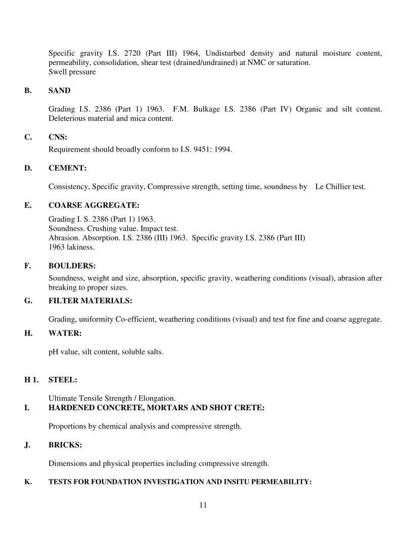
Specific gravity I.S. 2720 (Part III) 1964, Undisturbed density and natural moisture content,
permeability, consolidation, shear test (drained/undrained) at NMC or saturation.
Swell pressure
B. SAND
Grading I.S. 2386 (Part 1) 1963. F.M. Bulkage I.S. 2386 (Part IV) Organic and silt content.
Deleterious material and mica content.
C. CNS:
Requirement should broadly conform to I.S. 9451: 1994.
D. CEMENT:
Consistency, Specific gravity, Compressive strength, setting time, soundness by Le Chillier test.
E. COARSE AGGREGATE:
Grading I. S. 2386 (Part 1) 1963.
Soundness. Crushing value. Impact test.
Abrasion. Absorption. I.S. 2386 (III) 1963. Specific gravity I.S. 2386 (Part III)
1963 lakiness.
F. BOULDERS:
Soundness, weight and size, absorption, specific gravity, weathering conditions (visual), abrasion after
breaking to proper sizes.
G. FILTER MATERIALS:
Grading, uniformity Co-efficient, weathering conditions (visual) and test for fine and coarse aggregate.
H. WATER:
pH value, silt content, soluble salts.
H 1. STEEL:
Ultimate Tensile Strength / Elongation.
I. HARDENED CONCRETE, MORTARS AND SHOT CRETE:
Proportions by chemical analysis and compressive strength.
J. BRICKS:
Dimensions and physical properties including compressive strength.
K. TESTS FOR FOUNDATION INVESTIGATION AND INSITU PERMEABILITY:

12
Other properties, if tested shall be reported in the remarks column or foot note.
L. IMPROVED DEVICES FOR QUALITY CONTROL:
It is planned to introduce improved devices for achieving speedy and efficient quality control.
The canal rehabilitation works involve huge compaction of earth fill placement, and it is planned to introduce
“portable electronic density testers” for rapid on – site determination of compaction parameters like, moisture
content, wet density, dry density, and percentage of compaction in terms of Proctor density.
Scope and inspection activities are illustrated in ANNEXURE - II
FUNCTIONS OF FIELD LABORATORY SYSTEM:
I To carry out routine tests of soils and filter material, such as sieve analysis moisture content, needle density
tests, compaction efficiency, field density test etc., and to take samples from compacted fill from different
zones of the embankment.
II To carry out routine tests, like silt content in fine aggregates, F.M. sieve analysis, bulkage of fine
aggregates. Absorption, specific gravity and grade analysis, surface moisture content tests on coarse
aggregates. Slumps test of concrete and mortar and collect samples of concrete and mortar in
moulds as per approved frequency.
III To report results of tests performed in the field laboratories in the prescribed proformae pertaining
to the following tests.
A. SOILS:
1. Moisture content.
2. Density and compaction efficiency.
3. Needle penetration.
4. Proctors compaction.
5. Sieve analysis.
B. CNS:
1. Gradation analysis.
2. Shear Parameters.
3. Index properties.
C. SAND:
1. Presence of deleterious materials.
2. Grade Analysis and Fineness Modulus.
3. Bulkage.
D. COARSE AGGREGATES:
1. Grading.
E. FRESH CONCRETE AND MORTAR:
1. Water cement ratio.

13
2. Workability by slump test/flow table test.
F. BOULDER SAMPLE:
1. Absorption
2. Dimensions
3. Visual observation as regards weathering etc.
G. CEMENT:
1. Setting time by vicat needle test.
H. BRICKS:
All tests for physical properties except strength which will be conducted at central laboratory.
All other tests will be conducted in central Laboratory for which samples shall be sent by the field
laboratory to central laboratory.
The field laboratories will report the testing data in the prescribed forms meant
for soil, concrete masonry, filler and boulder pitching work, lining etc.
FUNCTIONS OF MOBILE LABORATORY (FIELD TESTS)
i. To carry out daily routine tests on compaction efficiency. Field density and field moisture content
determination test.
ii. To carryout daily routine tests like silt content, fineness modulus and gradation of fine Aggregates
and coarse aggregates.
iii. To carry out slump test, unit weight and Temperatures of concrete by using fresh concrete insitu
testing equipment, and to take fresh concrete as per the required frequency.
***********

14
CHAPTER – IV
DUTIES OF DEPUTY EXECUTIVE ENGINEER INCHARGE OF LABORATORY
i. To ensure proper up-keep and maintenance of laboratory equipment in laboratory.
ii. To ensure proper up-keep of records of all samples being tested in the laboratory as per prescribed
forms and communication to the concerned.
iii. To supervise the testing works of Assistant Engineer / Assistant Executive Engineers, laboratory
Assistants and personally to check the tests to the extent of 25 %.
iv. To prepare fortnightly review of all the tests results and submit to the Executive Engineer, Quality
Control.
v. To conduct any research work as may be assigned by the Executive Engineer.
vi. Steel rods as proposed to be used shall be tested for ultimate tensile strength elongation and bond etc.,
as per standards.
vii. Samples of welded rods, welded at site shall be collected and tested to the quality of welding.

15
viii. The Central laboratory has to conduct the test on the suitability of materials proposed from various
quarries of work, well in advanced of the actual execution of work, for which the construction staff
shall send material to the lab well in advance.
DUTIES OF ASSISTANT ENGINEERS / ASSISTANT EXECUTIVE ENGINEERS (LABORATORY)
Shall perform important tests as mentioned below:
A. CEMENT:
1. Fineness by Blains.
2. Normal Consistency.
3. Setting time.
4. Soundness.
5. Specific gravity.
6. Compressive strength.
7. Adulteration test.
B. SAND:
1. Sieve Analysis & Fineness modulus.
2. Test for organic impurities, silt & clay.
3. Decantation test for silt.
4. Specific gravity.
5. Unit weight and bulkage factor.
C. COARSE AGGREGATE:
1. Sieve Analysis and gradation.
2. Specific gravity.
3. Water absorption.
4. Examination of deleterious materials.
5. Crushing strength.
6. Impact.
7. Abrasion.
8. Flakiness index.
9. Alkali Silicate reactivity.
D. CONCRETE:
1. Consistency – slump or compaction factor.
2. Compressive strength.
3. Air content.
4. Yield per unit quantity of cement.
5. Mix design test.
6. Cement content.

16
E. MORTAR:
1. Consistency.
2. Compressive Strength.
3. Yield per unit quantity of cement.
4. Cement Content.
F. SOILS:
1. Gradation (Grain size analysis).
2 Consistency limits.
3. Porosity & Void ratio.
4. Specific gravity.
5. Swell pressure.
DUTIES OF LABORATORY TECHNICIANS / WORK INSPECTORS
i) To assist Assistant Engineers / Assistant Executive Engineers whenever required in laboratory and
field work.
ii) To perform tests in laboratory such as:
a) Compaction tests
b) Limit tests
c) Analysis of fine & coarse aggregates
d) Silt in fine aggregate
e) Slump test
f) Collection of samples of concrete and mortars for filling moulds for compaction test.
DUTIES OF LABORATORY ATTENDANTS
a) To keep instruments clean.
b) To assist Assistant Engineers / Assistant Executive Engineers and Laboratory Technicians in
conducting tests.
c) To prepare samples for test.
d) To arrange samples systematically.
Control of Inspection, Testing, and Measuring Equipment:
The identification and adjustment of all inspection, measuring and test equipment and devices will be done at
prescribed intervals as stated below against certified equipment having a known valid relationship to
nationally recognized standards. The equipment will be capable of controlling the delivery of material for
weighing so that inaccuracies in feeding and measuring during normal operation will not exceed 1% for water
and 3% for all aggregates. Periodical test will be made at least once in 2 weeks in case of equipment for
measuring water, cement and admixtures and at least once in every month in case of equipment measuring
sand and coarse aggregate. Other measuring equipments will be tested once in a year unless some defects are
noticed earlier, in which case these will be attended immediately.
Documents will be established and calibration procedures will be maintained including details of the
following:-

17
1. Equipment type. 2. Identification number.
3. Location. 4. Frequency of Checks.
5. Check method. 6. Acceptance criteria.
7. Action to be taken for unsatisfactory results, to ensure that the inspection,
measuring and test equipment are capable of the required accuracy and
precision.
**************
CHAPTER – V
DUTIES OF FIELD STAFF IN RELATION TO QUALITY OF WORKS
ASSISTANT EXECUTIVE ENGINEER / ASSISTANT ENGINEER CONSTRUCTION
ASSISTANT EXECUTIVE ENGINEER /
ASSISTANT ENGINEER QUALITY CONTROL
Shall see that the mark out of the area to be tackled is properly given, shuttering, centering, reinforcement are done as per drawings and technical specifications to record the Pre levels/foundation levels, and to see that mark-out for canal excavation is perfectly given as per drawings. Pre levels, classification levels and final levels of canal shall be taken as per specification and got verified by Quality Control Assistant Engineers / Assistant Executive Engineer.
1 Shall check the mark out foundation/pre levels and centering/shuttering reinforcement arrangements and inform the Assistant Executive Engineer/Assistant Engineer construction to rectify the defects if any. Shall certify the mark out of canal excavation as per drawings. Pre levels, classification levels and final levels of canal shall be checked.
Shall see that the construction equipment like mixers, vibrators, rollers, pumping, arrangements for curing/watering are arranged before starting of any work.
2 Shall check the adequacy of the construction equipment and curing/watering arrangements.

18
Shall see that sufficient quantities of input materials as per agreement specifications are made available at site of work and to arrange testing equipment, men and material required for conducting field tests on input materials or for sending samples of input materials to central lab.
3 Shall conduct the field tests on input materials and record the results and to inform the Assistant Executive Engineer/Assistant Engineer construction to rectify the defects if any. To send the samples of input materials to central lab as and when required. To conduct core tests and other field test as per I.S.I. incase of Embankment works.
Shall write O.K. Cards after area is ready to start the work and to inform the Assistant Executive Engineer / Assistant Executive Engineer Quality Control and Deputy Executive Engineer construction and take permission to start the work O.K. Card.
4 Shall check and write the O.K. Card and record the deviations, defects if any or otherwise to record the final OK and to inform he Deputy Executive Engineer / Executive Engineer quality control and to permit to start the work.
Shall supervise and ensure that correct quantities of input materials as per mix design communicated by the central laboratory are fed into the mixers/batching plants etc., and shall ensure adequate mixing time.
5 Shall make constant checks of the feeding of input materials mixing time and suggest the quantity of water depending on the moisture content of sand as and when required.
Shall ensure proper vibration, rolling etc., during course of day to day work and to provide men and material required for quality control staff.
6 Shall conduct slump test, record temperature of concrete, bore tests, proctor of concrete, proctor density etc., and to extract field samples of finished product to be sent to central laboratory later.
Shall ensure proper curing of samples extracted till the curing time is over and to make arrangements to send the samples to central lab.
7 Shall assist the Assistant Engineer / Assistant Executive Engineer Construction in Proper handling / transport of samples to central lab.
Shall ensure timely green cutting of concrete with proper air: water gun: nicking & chipping (wherever so warranted) so as to prepare the surface for concrete lift for effective bond at the lift / construction joints.
8 Shall check and see that the preparation of the surface is adequately done for starting the next lift.
Shall ensure proper curing/watering and allow removal of centering only after the time limit prescribed in the specifications and to see that the surfaces are finished to the plumb/straight lines etc., after removal of shuttering.
9 Shall check the adequacy of curing/watering and see that the final surfaces are finished neatly plumb/straight lines etc.
Shall maintain (1) mark-out register (2) OK Card files.
10 Shall maintain registers of field test conducted.

19
DEPUTY EXECUTIVE ENGINEER (CONSTRUCTION)
DEPUTY EXECUTIVE ENGINEER (QUALITY CONTROL)
Shall exercise proper check over all the activities of Assistant Engineer/Assistant Executive Engineer, Construction.
1 Shall exercise proper check over all the activities of Assistant Engineer/Assistant Executive Engineer / Quality Control.
Shall verify the foundation / pre-levels check the mark-out, reinforcement / centering etc., invariably for all works.
2 He shall invariably check foundation of all components of works. Final OK is to be recorded before the work is started. Where heavy reinforcement is involved the same also should be checked invariably and final OK is to be recorded.
Shall check feeding of input materials, mixing, placing, vibration rolling etc.
3 Shall check at random feeding of input materials, mixing, placing, vibration rolling etc.
To ensure that the cement used at site of work is tested in the central laboratory.
4 Shall check the test reports of cement, date of manufacture etc., and satisfy before starting of the work.
Shall write the OK cards after satisfying about the arrangements made for starting of the work and report to the Executive Engineer / Construction, Executive Engineer / quality control accordingly.
5 Shall write O.K. cards as and when required and inform the Executive Engineer / Quality Control accordingly.
Shall see that samples of finished products are transported to the central laboratory.
6 Shall conduct the field tests like slump, temperature of concrete at random.
Shall personally supervise the rectifications pointed out by Executive Engineer Construction / Executive Engineer Quality Control.
7 Shall intimate the defects if any to the Executive Engineer Construction and Executive Engineer Quality Control. Check and verify whether rectifications are done as per the norms laid down in the contract specifications.
Should arrange to get the foundations of soil tested incase of weak soil over which heavy Embankments are proposed.
8 Shall assist the Deputy Executive Engineer Construction in conducting these tests.
He should send disturbed soil samples in various reaches well in advance to central laboratory and get the soil tested for various properties and obtain OMC and MDD values.
9 Shall assist the Deputy Executive Engineer Construction in sending the samples to central laboratory.
Shall order temporary suspension of work if any serious defects are noticed and shall intimate immediately to Executive Engineer Construction and Executive Engineer Quality Control.
10 Shall order temporary suspension of work if any serious, defects are noticed and shall intimate immediately to Executive Engineer Construction and Executive Engineer Quality Control.
DUTIES OF EXECUTIVE ENGINEER
EXECUTIVE ENGINEER CONSTRUCTION
EXECUTIVE ENGINEER QUALITY
CONTROL

20
1 Shall supervise, check, advise, and instruct the A.E./A.E.E./D.E.E. Construction regarding discharge of their functions properly.
1 Shall supervise, check, advise and instruct the A.E./A.E.E./D.E.E. Quality control regarding discharge of their functions properly.
2 Shall intimate the Executive Engineer quality control regarding signing of agreement for starting of any new work, duly endorsing a copy of work order. Shall supply copies of contract documents, drawings Construction program etc., to Executive Engineer Quality Control, and Superintending Engineer Designs and Inspection Circle.
2 Shall maintain copies of approved Designs, reports, contract document, drawings, construction program, extracts of inspection notes etc., and shall see that his subordinates go through the above documents.
3 Shall see that all ingredients of concrete, masonry are got tested before use. Shall see that the soils are tested for various properties like OMC, MDD, etc., before starting of Embankment work.
3 Shall remind, ensure and verify whether test results are available or not before starting up of any new work.
4 Shall see that all the Machinery / equipment being used by the contractor is got periodically calibrated.
4 Shall assist in upkeep and calibration of equipment.
5 Shall see that OK Cards are written and kept at site of work before starting of any work.
5 Shall inspect and sign on O.K. Cards during field visits.
6 Shall order the suspension of work if any defects are noticed or reported by quality control staff and resume the work only after rectification of defects in the presence of quality control staff
6 Shall order the suspension of work if any defects are noticed or reported by quality control staff and intimate his counter part to see that defects are rectified. If not rectified the matter is to be reported to the Superintending Engineer Quality Control.
7 Foundations and reinforcement, shuttering, centering where heavy reinforcement is involved is to be checked by Executive Engineer invariably before starting the work.
7 Foundations and reinforcement, shuttering, centering where heavy reinforcement is involved is to be checked by Executive Engineer invariably before starting the work.
8 Shall jointly inspect the site with quality control Executive Engineer in case variation in classification is less than 10% (+/-) and finalize the classification.
8 Shall jointly inspect the site with Construction Executive Engineer in case variation in classification is less than 10% (+/-) and finalize the classification.
9 Shall personally see that the samples to the laboratories like A.P.E.R.L. / N.C.B. are sent regularly, obtain the results and communicate the same to Executive Engineer quality control.
9 Shall peruse and keep track of sending of samples to A.P.E.R.L. / N.C.B. and to keep record of results received.
10 Shall take the help of quality control Executive Engineer whenever a dispute is referred to Technical Expert.
10 Shall co-ordinate with the Executive Engineer/Construction division render assistance in resolving the issues referred to technical expert.

21
************
CHAPTER – VI
CO-ORDINATIONS
The construction staff and quality control staff must act in tandem as a single unit to achieve good
quality of the finished product and construction as per the contract specifications.
Construction staff should make it a point to inform the quality control staff, the date of starting of any
component of the work well in advance so as to enable the quality control staff to schedule their work plan
and attend the particular work on that particular date.
In turn quality control staff should program their itenary, so as to attend the work on the dates required
by the construction staff and ensure that the progress of work is not hampered.
The quality control staff shall be responsible for exercising the various field checks with reference to
drawing and specifications laid down in respective I.S. code during construction and carrying out all the
laboratory and field tests on materials used for construction and reporting through their higher officer, to the
field staff for ensuring quality.
The Defects, if any, noticed by the quality control staff during their course of inspection shall be
brought to the notice of the construction staff then and there. It is the primary responsibility of the Quality
Control & Inspections shall to draw the attention of the construction staff, whenever they notice defective
work during their course of inspection. It is the duty of the construction staff to attend to the rectification and
maintain proper specifications as pointed out by their counter part of the Quality Control organization.
The Assistant Engineer / Assistant Executive Engineer (Quality Control) can address Assistant
Engineer / Assistant Executive Engineer or Deputy Executive Engineer construction regarding defects,
rectification testing etc.

22
As far as possible the defects are to be rectified in the presence of the Quality Control staff and the
payment shall be effected only after the Quality Control Staff are fully satisfied with the rectification and
quality of work. Any rectification done subsequently without any intimation and presence of Quality Control
staff shall be at the sole responsibility of the construction staff.
The quality control staff can not supervise the placement of concrete on a mix to mix basis
continuously. They can only conduct random check of input materials, mixing time, placement of concrete,
vibration etc. It is the primary responsibility of the construction staff to ensure adequate supervision of mix to
mix placement of concrete.
The Operations of the Quality Control Staff shall not interfere in any way, with the executive powers
vested with the officers in charge of execution. They will also in no way diminish the responsibility of the
officers in charge of execution. The field officers in charge of works are primarily responsible for the quality
of all works and to carry out the work as per the technical specifications.
In case of difference of opinion between quality control staff and construction staff, it should be sorted
out by way of discussions in cordial atmosphere and mutual trust as per the guide lines indicated below. In
case it involves any design feature/problem/aspect, the design office should be duly consulted and the advice
given by the designer should be accepted.
Where the objection raised by the Assistant Engineer / Assistant Executive Engineers of quality
control is not acceptable to his counter part by the construction unit, the Deputy Executive Engineer of
construction shall discuss with his counter part of quality control to settle the objection. If they fail to arrive
at a solution, the matter may be reported to the ‘Executive Engineer/Construction who would discuss the issue
with the Executive Engineer, Quality Control. In case Executive Engineer, Quality Control is not readily
available at site, the Executive Engineer, Construction may take suitable decision and intimate the Executive
Engineer, Quality Control and Superintending Engineer, Construction of the decision taken with reasons.
In case of difference of opinion between Executive Engineer, Construction and Executive Engineer,
Quality Control, it would be referred to Superintending Engineer, Construction, who would discuss the matter
with Superintending Engineer, Quality Control and settle the issue. Similarly, when the Superintending
Engineer, Quality Control is not readily available, the Superintending Engineer Construction can over rule
after recording the reasons in writing. In such cases the Superintending Engineer, Construction has to discuss
with Superintending Engineer, Quality Control at the earliest opportunity and modify his earlier orders, if
necessary.
In case there is a difference of opinion between Superintending Engineer, Construction and Quality
control the matter would be referred to Chief Engineer whose decision shall be final and binding on all. Work
should immediately be suspended and not allowed to resume until the defects pointed out by quality control
and inspection staff are rectified. Disciplinary action shall be taken against the construction staff concerned
who fragmentally violate this rule and appropriate measures taken against the contractor to rectify
unacceptable work at contractor’s cost.
The construction and quality control staff shall keep a regular liaison with the Geologist in respect of
all Geotechnical problems and enlist his input on foundations of structures & dams, Cut off Trenches,

23
tunneling; contact/consolidation/curtain grouting, Rock/Excavation Slopes (stability of slopes); protection
measures; permeability/Water loss tests etc., as well as any geological problem. The advice rendered by the
Geologist should be discussed with the Designers and duly respected and implemented.
**************
CHAPTER – VII
QUALITY ASSURANCE
QUALITY ASSURANCE:
All planned and systematic strategies and actions necessary to generate adequate confidence that input
and out put product will satisfy given requirements of quality and all the components of works perform
satisfactorily during life period of service, adequate quality checks as analyzed during construction is a record
which speaks of “Quality Assurance”. It comprises planning and policies, education and training standards
and specifications, contracts and agreements, and quality control Quality assurance is to assume that the
materials as per standard and as per the requirements have gone into the production of concrete, earth,
masonry work etc. This is achieved by evaluating the quality checks during construction and post
construction tests made and compared.
List of Documents:
Each QC laboratory should hold the following documents:
• Quality control manual.
• Technical Records: Specification, Contract documents, inspection and Test Procedures, relevant
standards/codes of practice.
• Mill Certificates.
• Corrective action records.
• Material test reports, test reports of cores.
• Inspection Reports.
• Photographic/Video film records of construction which may not remain accessible after
commissioning of the project.
• Non-conformance reports.
• Statistical evaluation reports.
• Technical Literature.
• Standardization of records.
Quality Control Personnel should hold the following Documents:
• Data of test.
• Area where material is used.
• Test method with reference to Standards.
• Testing results, including those of cores of concrete.
• Acceptance criteria.

24
• Statement of compliance / non-compliance.
• Remarks.
• Test personnel signature.
TEST OF DRILL CORES:
A good canal lining should be strong, durable and of optimum water tightness. A well graded concrete
mix, composed of sound aggregates with a close control on its workability as well as placement on a dense
sub-grade, followed by good finishing and adequate curing shall ensure a sound lining capable of a long
service life.
As the lining work progress, testing of the output should be taken up on a regular basis accordingly, to
evaluate the quality of concrete lining completed and cured (for 28 days) in respective reaches, cores should
be taken of lining concrete. Frequency of drill cores could be say one core each from bed, side lining per
2.000 square meter of insitu-lining. The frequency shall be decided by the engineer in consultation with the
project Chief Engineer.
The cores should be inspected for
Segregation
Honey combing and
Thickness of lining
The cores should be tested for
Density (gm/cc)
Compressive strength and Water absorption.
A standard test cylinder has a diameter one-half of its height viz., the (L) Length/ Diameter (D) ratio is
2. However, the cores taken from in-situ-lining shall not have these relative dimensions and consequently
L/D ratio will not be 2. Accordingly, the test strengths of these cores should need to be corrected. The
curve in Attachment be used to correct the indicated strengths so that these will be comparable with those
obtained from standard specimens. The equivalent cube strength of the concrete shall be determined by
multiplying the corrected cylinder strength by 5/4. The correction factor can also be determined from the
curve on page 13 of I.S.: 516 – 1959. (curve enclosed as Annexure-III). The cores should be properly
stacked in sheds.
Complete data and test results of cores should be meticulously recorded. It should include.
• Location of test core (chainage: bed and side slope lining panel).
• Grade of concrete mix, maximum size aggregate of in-situ lining, slump, W/C ratio.
• Density of standard specimen, prepared and cured in laboratory.
• Density of test core (gm/cc).
• Thickness of lining exhibited by the test core.
• Compressive strength of test core.
• Corrected compressive strength of core (as per curve of Annexure III) in kg/cm
• Remarks-visual observations on any honey combing/segregation viz. lack of consolidation be
recorded.

25
Acceptance Criteria:-
Concrete in the member represented by a core test shall be considered acceptable if the average equivalent
cube strength of the cores is equal to at least 85% of the cube strength of the grade of concrete specified for
the corresponding age and no individual core has strength less than 75 percent.
************
CHAPTER – VIII

26
MONITORING THROUGH CONTROL CHARTS
Monitoring of quality control and assessment of the trend of quality control being exercised by the
Project Management is best done through control charts. Indian standards I.S: 397 (Parts 1 to III) cover
control charts for general and special application. These charts are based on compressive strengths of cement
and concrete tests specimens. Control charts for cement strengths are for different test ages (i.e., 3, 7 and 28
days) and both for strengths of individual test and moving average of five tests over periods of time control
charts for concrete strengths are also constructed in more or less the same manner as per cement. In addition
to the test data, the control charts also incorporate certain reference line constituting a frame work within
which the degree of control actually achieved is assessed and remedial measures initiated where called for.
The reference lines are termed the “Warning” and “Action Limits”. The warning and action lines provide
feed-back for timely remedial measures.
The illustration of preparation of control charts of cement & concrete are appended in Annexure IV.
Preparation of quality Control Reports and Control Charts is considered to be one of the step towards
the process of achieving good construction quality. The Control Charts should be prepared as a concurrent
exercise as the work proceeds. These should be constantly scanned to identify indication of any significant
deviation in quality and initiate the remedial action promptly.
STANDARD DEVIATION (I.S. 10262 – 1982)
The estimated standard deviation of given grade of concrete can be calculated from the result of
individual tests of concrete, using the formula:
S = ∑∆2/ (n-1)
Where ∆ = The deviation of the individual test strength from the
average strength of ‘n’samples, and
n = number of sample test results.
If at least 30 test results for a particular grade of concrete at site with the same materials and
equipment are not available, the standard deviation, S for the corresponding degree of control, may be
assumed from the following tabulation, given IS: 10262 – 1982.
Degree of Control
------------------------------------------------------------------------------------------------------------
Grade of Concrete Assumed standard deviation, S N/mm2
D.L’s
------------------------------------------------------------------------------------------------------------

27
Very good Good Fair
M 10 2.0 2.3 3.3
M 15 2.5 3.5 4.5
M 20 3.6 4.6 5.6
M 25 4.3 5.3 6.3
M 30 5.0 6.0 7.0
M 35 6.3 6.3 7.3
M 40 5.6 6.6 7.6
_______________________________________________________________________
Degree of Field Control (as per I.S. 10262 – 1982)
------------------------------------------------------------------------------------------------------------
Degree of
Control Condition of production
------------------------------------------------------------------------------------------------------------
Very Good Fresh cement from single source and regular tests weigh-batching of all materials,
control of aggregate, grading and moisture content, control of water added, frequent
supervision, regular workability and strength tests, and good field laboratory facilities.
------------------------------------------------------------------------------------------------------------
Good Carefully stored cement and periodic tests; weigh – batching of all materials, controlled
water; graded aggregate; occasional grading and moisture tests; periodic check of
workability and strength; intermittent supervision, and experience workers.
------------------------------------------------------------------------------------------------------------
Fair Proper storage of cement, volume batching of all aggregate, allowing for bulking of
sand, weigh-batching of cement, water content controlled by inspection of mix, and
occasional supervision and tests.
------------------------------------------------------------------------------------------------------------
ACCEPTANCE CRITERIA OF CONCRETE AS PER IS 456: 2000:
Compressive strength:
The concrete shall be deemed to comply with the strength requirements when both the following conditions
are met:
a) The mean strength determined from any group of four consecutive test results compiles
with the appropriate limits in col2 of Table 11.

28
b) Any individual test result complies with the appropriate limits in col 3 of Table 11.
Table 11 Characteristic Compressive Strength Compliance Requirement
Specified Grade Mean of the Group of Individual Test
4 Non-overlapping Results in N/mm2
Consecutive Test results
in N/mm2
(1) (2) (3)
M15 ≥ fck + 0.825 X established ≥ fck – 3 N/ mm2
Standard deviation (rounded
off to nearest 0.5 N/ mm2
or
fck + 3 N/ mm2 ,
whichever is greater
M 20 ≥ fck + 0.825 X established ≥ fck - 4 N/ mm
2
Or above Standard deviation (rounded
off to nearest 0.5 N/ mm2
or
fck + 4 N/ mm2 ,
whichever is greater
NOTE: In the absence of established value of standard deviation, the values given in table 8 may be assumed
and attempt should be made to obtain results of 30 samples as early as possible to establish the value of
standard deviation.
If the concrete is deemed not to comply pursuant to the structural adequacy, the parts so affected shall be
investigated and any consequential action as needed shall be taken.
Concrete of each grade shall be assessed separately.
Concrete shall be assessed daily for compliance.
Concrete is liable to be rejected if it is porous or honey-combed, if placing has been interrupted without
providing a proper construction joint, the reinforcement has been displaced beyond the tolerances specified or
construction tolerances have not been met. However, the hardened concrete may be accepted after carrying
out suitable remedial measures to the satisfaction of the engineer-in-charge
Coefficient of variation
The Co-efficient of variation (COV) and Standard Deviation are the two statistical tools which are
utilized to indicate the level of quality control. A high COV indicates poor control and a low COV indicates
good control. The following Table gives the ratings that are commonly assigned to various COVs for

29
deciding the level of control of concrete strengths. These standards represent the average of 28 days
compressive strength tests:-
Coefficient of variation (COV) for different control standards (%)
-----------------------------------------------------------------------------------------------------------
Excellent Good Fair Poor
------------------------------------------------------------------------
General construction Below 10 10 to 15 15 to 20 Above 20
------------------------------------------------------------------------
Lab. Control Below 5 5 to 7 7 to 10 Above 10
------------------------------------------------------------------------------------------------------------
Standard Deviation and Co-efficient of Variation (COV) will be worked out for different
Grades of concrete in addition to the 28 day compressive strength. This will be done on
a continuing basis and updated regularly and documented in the following format :-
The COV
ratings for
concrete for
different
control
standards
are indicated
in the table.
Assumed Standard Deviation:
When sufficient test results for a particular grade of concrete are not available, the value of standard deviation
given in Table 8 may be assumed for design mix in the first instance. As soon as the results of samples are
available, actual calculated standard deviation shall be used and the mix designed properly.
However, when adequate past records for a similar grade exist and justify to the designer a value of standard
deviation different from that shown in Table 8, it shall be permissible to use that value.
Table 8: Assumed Standard Deviation
(Clause 9.2.4.2 and Table 11)
------------------------------------------------------------------------------------------------------------
Grade of concrete Assumed Standard Deviation
N/mm2
------------------------------------------------------------------------------------------------------------
S.No. Grade
of
concrete
Period No. Of
Samples
Ave.28 day
compressive
strength
Standard
Deviation
Co-
efficient
of
variation
(COV)
Degree
of field
control
Re-
marks

30
M10 3.5
M15
M20 4.0
M25
M30
M35
M40 5.0
M45
M50
NOTE: The above values correspond to the site control having proper storage of cement, weigh batching of
all materials, controlled addition of water, regular checking of all materials, aggregate grading and moisture
content and periodical checking of workability and strength. Where there is deviation from the above the
values given in the above table shall be increased by 1 N/mm2.
------------------------------------------------------------------------------------------------------------
INSPECTION AND TESTING OF STRUCTURES
Inspection – Immediately after stripping the formwork, all concrete shall be carefully inspected and any
defective work of small defects either removed or made good before concrete has thoroughly hardened.
In case of doubt regarding the grade of concrete used, either due to poor workmanship or based on results of
cube strength tests, compressive strength tests of concrete on the basis of and / or load test may be carried out.
Core Test
The point from which cores are to be taken and the number of cores required shall be at the discretion of the
Engineer-in-Charge and shall be representative of the whole of concrete concerned. In no case, however,
shall fewer than three cores be tested.
Core shall be prepared and tested described in IS : 516-1959:
Concrete in the member represented by a core test shall be considered acceptable if the average equivalent
cube strength of the cores is equal at least 85 percent of the cube strength of the grade of concrete specified
for the corresponding age and no individual core has strength less than 75 percent.
In case the core test results do not satisfy the requirements of or where such tests have not been done, load test
may be resorted to.
31
CHAPTER – IX
O.K. CARDS
GENERAL
Since O.K. Cards contain important entries / information on execution of works at all stages and are
liable to be referred / perused at a later stage also, particularly during the Internal Quality Audit of works. The
O.K. Cards shall be maintained in duplicate in two colours. The green coloured card shall form a part of the
record of Q.C. /Q.A. Wing and the red coloured card remains in the custody of construction Wing. The O.K.
Cards, relating to any particular work, shall be put in a round shaped tin box and placed right at the
construction site. The exterior of the tin box shall be painted red. After the particular work has been
completed (say concrete placement has been completed in a particular lifts likewise say fill placement has
been completed in a particular layer etc., ) the two O.K. Cards shall be removed from the tin box and filed in
the permanent record files of the construction and Q.C./Q.A. divisions respectively. Senior Officers shall also
check the O.K. Cards during their field inspections to ensure that those are being maintained and
properly/genuinely filed.
An O.K. Cards is a condensed form of specifications and essential requirements for achieving
specified workmanship and quality level of output. Each work is sub-divided into various construction
activities in proper sequence/order of construction. Such activities are listed in chronological order on the
O.K. Cards.

32
For various stages of construction activities where laboratory tests or checks with reference to drawing
and specification are required from quality control unit, O.K. Card System shall be followed. The O.K. Cards
should be made available on the site in a regular manner.
The O.K. Card consists of 3 columns. Besides, the location and type of work, the first column is to be
filled by the construction Agency (Contractor) by preparing each feature and making it ready for inspection
by the project Construction Engineer, who Okays through his signature and then puts up the Q.C/Q.A
engineer for his final O.K.
The Assistant Engineer/Assistant Executive Engineer (Construction) will prepare two copies of O.K
Cards by filling in the column meant for the construction staff and hand over to the Assistant
Engineer/Assistant Executive Engineer (Quality Control). The Quality Control staff at actual work site shall
check the requirement or shall perform necessary tests under the guidance of Assistant Engineer/Assistant
Executive Engineer, Quality Control. The Assistant Engineer/Assistant Executive Engineer, Quality Control
will scrutinize the O.K. Card and finally Okay the particular activity of work if anything adverse/violative of
specifications or drawings is not observed. Should anything otherwise be found, the O.K. Card shall not be
signed by him and he will ask the Assistant Engineer/Assistant Executive Engineer (Construction) for
necessary rectification.
Subsequently, O.K. Card should refer to the defect removed, if pointed out previously.
Senior Officers during their inspections should also see the OK cards and record their observations, if
any, against the particular activities in progress.
On the WUA level works, the representatives of WUA should also be associated with OK card system
and signing of OK cards. Accordingly a separate column for WUA be included in the OK cards.
After processing through various levels and entering observations one copy of the O.K. Card (Red
Colour Card) shall be retained with the Executive Engineer (Construction) for record and reference and the
other copy shall be forwarded to the Executive Engineer Quality Control for record.
Specimen of O.K. Cards for various works such as Earthen embankment, Canal lining (sub-grade
preparations, cost-in-situ CC lining) Grouting & concrete work are enclosed.
O.K. CARD FOR EARTH WORK EMBANKMENT
S. No. Description Contractor Construction Quality Remarks.
Engineer Control Engineer
1. Date
2. Location of work from
Km------------ to Km ----------
3. Elevation (R.L.)
4. Surface preparation, whether
as per specification.

33
5. Type of Compaction
equipment used
6. Location of test at Km.
7. Thickness of loose layer.
8. Initial moisture content.
9. Removal of over size.
10. Top level after compaction of layer.
11. Wet density.
12. Moisture content in rolled fill
13. Dry density
14. Laboratory OMC and MDD
15. Compaction efficiency
16. Embankment of instruments
devices (in case of earth dam)
17. Methodology of addition of
Moisture (whether through spray
from sprinkler tanker)
18. Manual compaction, if any
19. Layer passed
20. Any other remarks.
Sign of Sign of Sign of
Contractor GOAP GOAP
With date (Construction (QC Engineer)
Engineer) with date
with date

34
O.K. CARD FOR SUB GRADE PREPARATION OF CANAL LINING
S. No. Description Contractor Construction Quality Remarks.
Engineer Control Engineer
____________________________________________________________________
1. Date
2. Location
3. Whether sub-grade is prepared
as per specification in case of
c) ROCK-(Over excavation)
d) Swelling soils (Treatment
With CNS soils)
e) Over excavation in soils
4. Whether the profile of canal
section is prepared to model section.
1. Whether porous plugs cast
as per specification.
6. Whether the work of laying the
filter media is carried out as per
approved drawing in case of
a) Porous Plugs
b) Longitudinal and transverse
drains.
7. Flap valves placed as per drawing
8. Whether sub-grade is wetted to
150 mm depth as per specification.

35
9. Compaction of Sub-grade
to specified density.
10. Methodology of compaction.
11. Methodology of moistening,
Wetting of sub-grade.
12. Any other remarks.
Sign of
Sign of Sign of Sign of
Contractor GOAP GOAP
With date (Construction (QC Engineer)
Engineer) with date
with date O.K. CARD FOR CAST – INSITU CONCRETE LINING
Signatures of
S.No. Description Contractor GOAP GOAP REMARKS
Construction Engineer Q.C Engineer
1. Date
2. Location from Km ------ to ---------
Km ------------ bed side slope L/R.
3. Proportion of the mix / Grade of concrete
4. Materials
a) Coarse aggregate nominal maximum size 40 mm. 20mm & 10 mm
b) Fine aggregate, F.M. of sand
c) Cement make / Date of Manufacturer
d) Admixtures make / date of mfr. and % used.
5. Method of concrete mix
a) Mix vol./weight
b) Batching plant (by weight)
6. Transport
a) By transit mixer
b) By mobile self loading / weigh-batching & mixing and transporting (viz moving B & M Plant)
7. Temperature of concrete specified.
8. Temperature of concrete as placed.
9. Slump
a)Design slump
b) i. Slump at the batching plant
ii. Slump at the site of placement.
10. Water Cement Ratio.
11. Method of consolidation
Mechanical vibrators / screed vibrator / Plate vibrator
12. Whether contraction /
Joints are provided as per approved drawings.

36
13. Treatment of cold joint/joints
14. Curing: Water curing/curing by membrane form of curing
Compound.
15. Quality / Workman ship of concrete laid.
16. No. of C.C. cubes casted.
17. Any other remarks.
Sign of Sign of Sign of
Contractor GOAP GOAP
With date (Construction (QC Engineer)
Engineer) with date
with date O.K. CARD FOR STRUCTURAL CONCRETE WORKS
Particular of structure: Location:
Signatures of
S.No. Description Contractor GOAP GOAP REMARKS
(CS) (QCS)
1. Date
2. Grade of Mix
3. Location of work
a. Foundation (with elevation)
b. Super structure (with elevation)
4. Methodology of preparation of surface joints
a) Green cutting
b) Sand Blasting
c) High pressure water blasting.
5. Materials
a) Coarse aggregate of maximum nominal size /
Grade analysis.
b) F.M. of sand
c) Cement make/date
d) Water quality
6. Tools and plants
a) Form work details of shuttering
Should be checked with dimensions.
b) Mixer
c) Vibrators

37
7. Batching
8. Temperature of concrete specified in
technical specifications.
9. Temperature of concrete as placed
10. SLUMP
a) Design slump
b) At the batching and mixing plant
c) At the site of placement
11. Method of placing.
Signatures of
S.No. Description Contractor GOAP GOAP REMARKS
(CS) (QCS)
12. Method of consolidation
13. Water cement ratio
14. Treatment of construction joints
15. Embedments
16. Water stopper
17. Concrete finish (Wood
float steel trowel)
18. Quantity of concrete laid.
19. No. of CC Cubes cast
20. Checking of reinforcement
21. Curing arrangements
22. Any other remarks.
Sign of Sign of Sign of
Contractor GOAP GOAP
With date (Construction (QC Engineer)
38
Engineer) with date
with date
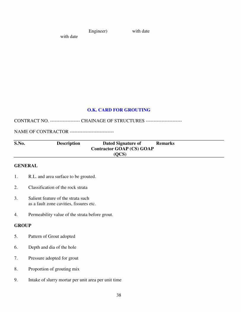
O.K. CARD FOR GROUTING
CONTRACT NO. ------------------- CHAINAGE OF STRUCTURES -----------------------
NAME OF CONTRACTOR ----------------------------
S.No. Description Dated Signature of Remarks
Contractor GOAP (CS) GOAP
(QCS)
GENERAL
1. R.L. and area surface to be grouted.
2. Classification of the rock strata
3. Salient feature of the strata such
as a fault zone cavities, fissures etc.
4. Permeability value of the strata before grout.
GROUP
5. Pattern of Grout adopted
6. Depth and dia of the hole
7. Pressure adopted for grout
8. Proportion of grouting mix
9. Intake of slurry mortar per unit area per unit time

39
10. Total Quality of intake
11. Final permeability value of the strata after gout.
12. Whether the grout strata is OK.
Signature of
Contractor GOAP/C/S/ (GOAP/Q/CS)
D.E.E. / E.E. AE/AEE
D.E.E. /E.E.
CHAPTER – X
TESTS TO BE PERFORMED ON MATERIALS
MATERIAL TEST METHOD
Cement a) Chemical IS: 4032-1985
i) Sio2, Al2O3, Fe2O3, CaO
MgO, SO2, Insol residue & Loss
On ignition
ii) Alkalies & Chlorides
iii) Free Lime
b) Physical
i. Specific gravity
ii. Fineness
iii. Soundness
iv. Compressive Strength
v. Drying shrinkage
Coarse Aggregates i) Sieve Analysis IS: 2386-1963
ii) Flakiness index
iii) Elongation index PART – I
iv) Deleterious materials
v) Specific gravity PART – II
vi) Bulk Density
vii) Moisture content PART – III
viii) Absorption value
Mechanical tests PART - IV
ix) Aggregate crushing value
x) Impact value PART – V
xi) Abrasion value

40
xii) Potential reactivity of aggregate PART – VI
xiii) Petro-graphic examination
xiv) Alluli Aggregate reactivity test PART – VII
Water Chemical
i) CL, SO4, Organic & Inorganic Solids, IS: 3025-1968
pH, Alkalinity / Acidity
ii) Setting time of mortar IS: 516 – 1959
iii) Relative strength of concrete IS: 1199-1959
Admixtures i) Relative water content IS: 9103-1959
ii) Bleeding IS: 9103-1959
iii) Relative strength IS: 516-1959
iv) Setting time IS: 8142-1959
v) Relative length change IS: 1199-1959
MATERIAL TEST METHOD
Concrete a) Fresh Concrete IS : 516 - 1959
i) Air content
ii) Vibration
iii) Yield
iv) Temperature measurement
v) Mix proportions
vi) Water cement ratio
b) Workability test IS: 516-1959
i) Slump test Usual procedure
ii) Compaction Factor test IS:CED2(CESS)
ASTM C 597-83
c) Hardened Concrete BS 4408
i) Compressive strength PART 5:1974
ii) MDT Tests IS:CED 2(3890)
iii) Ultrasonic pulse velocity ASTM C805-85
iv) Rebound Hammer BS 4408
PART – 1971
d) Special Test
i) Microscopy
ii) Non-destructive
iii) Core Testing
Embankment i) disturbed grain size analysis IS 2720 Part (iv) 1965
ii) Proctors compaction IS 2720 Part (vii & viii) 1965
iii) Atterbergs Limits IS 2720 Part (v) 1970
iv) Permeability IS 2720 Part (xvii) 1966
v) Shear test IS 2720 Part (xiii) 1972
vi) Specific gravity IS 2720 Part (iii) 1964

41
*****************
CHAPTER – XI
LIST OF EQUIPMENT FOR CEMENT AND CONCRETE TESTING
TEST EQUIPMENT
1 A. CEMENT Flame Photometer a) Chemical Spectrophotometer i) Alkalies Potentiometer, Silver Electrode, Calomel ii) Minor, major oxides by Calorinetry Reference Electrode, Salt bridge. iii) Chloride Water Distillation still, even, Hot plate, Balance
(Acc.0.0002 g) Muffle furnace (upto 1200 c). iv) General Platinum Crucibles, conductivity Bridge, pH
Meter, Sample Divider for powers, physical balance (Cap. 150 g)
b) Physical i) ii) iii) iv) v) vi) vii)
Fineness Soundness LeChatelier Consistency and setting time. compressive strength Heat of Hydration Drying shrinkage General
Blaines Apparatus, stop watch. Lachatelier Moulds, hot water batch Autoclave, length comparator moulds 25 x 25 x 250 mm.
B AGGREGATES & CONCRETE a) i) ii) iii) iv) v)
General Crushing value Impact value Abrasion value Alkali Aggregate Reactivity Flakiness & Elongation indices.
Vicat Apparatus, moulds setting time needles and plunger compression testing machine (50 tonnes). Vibrating machine moulds 50 sq.cm. Area, calorimeter, beckmann thermometer length comparator. flow table, stop watch, timer, temperature controlled oven, humidity chamber, incubator, physical balance (ACC 0.001 g) balance (cap. 5 kg. ACC 1g), control room (Temp. controlled curing tanks), set of
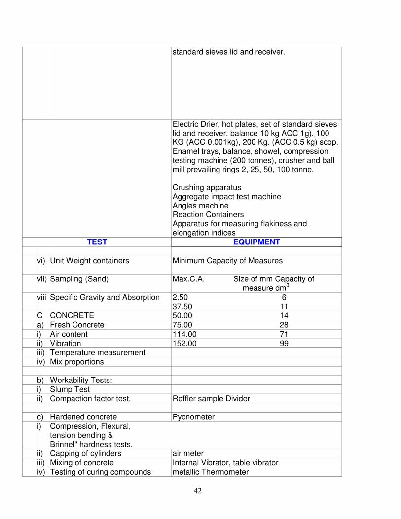
42
standard sieves lid and receiver.
Electric Drier, hot plates, set of standard sieves lid and receiver, balance 10 kg ACC 1g), 100 KG (ACC 0.001kg), 200 Kg. (ACC 0.5 kg) scop. Enamel trays, balance, showel, compression testing machine (200 tonnes), crusher and ball mill prevailing rings 2, 25, 50, 100 tonne. Crushing apparatus Aggregate impact test machine Angles machine Reaction Containers Apparatus for measuring flakiness and elongation indices
TEST EQUIPMENT vi) Unit Weight containers Minimum Capacity of Measures vii) Sampling (Sand) Max.C.A. Size of mm Capacity of
measure dm3 viii Specific Gravity and Absorption 2.50 6 37.50 11 C CONCRETE 50.00 14 a) Fresh Concrete 75.00 28 i) Air content 114.00 71 ii) Vibration 152.00 99 iii) Temperature measurement iv) Mix proportions b) Workability Tests: i) Slump Test ii) Compaction factor test. Reffler sample Divider c) Hardened concrete Pycnometer i) Compression, Flexural,
tension bending & Brinnel" hardness tests.
ii) Capping of cylinders air meter iii) Mixing of concrete Internal Vibrator, table vibrator iv) Testing of curing compounds metallic Thermometer

43
Equipment as in IS: 1199 for Determination of constituents, slump cone Apparatus,
d) Special Tests Compaction Factor apparatus, Universal Testing
i) Microscopy Machines with accessories (Cap. 100 tonnes). ii) Non-Destructive Concrete workability meter. iii) Core Testing Capping moulds Laboratory concrete mixer Reluctance meter Optical microscope, grinding and polishing
equipment, ultrasonic pulse velocity, rebound hammer core drilling machine, RCC cutting machine, thermal conductivity apparatus permeability apparatus.
CHAPTER – XII
Name of Work:-
Determination of field moisture and dry density of compacted earth fill
1. Date
2. Sample No.
3. Wt. Of Core Cutter = WC
Wt. of core cutter + wet soil = Ws
4. Wt. Of Wet Soil in gms (Ws-Wc) = W
5. Wet Density gms / c.c. = W / V
6. Moisture container No.
7. Wt. Of container + Wet Soil in gms.
8. Wt. Of container + dry soil in gms.
9. Wt. Of moisture in gms (m)
10. Wt. Of dry soil in gms (d)

44
11. % moisture content (m.c) = m x 100/d
12. Dry density in gms /cc.
SIGNATURE OF A.E. / A.E.E. / D.E.E.
DETERMINATION OF FIELD DENSITY BY SAND
REPLACEMENT METHOD
SCOPE:
The object of the test is to determine the dry density of natural or compacted soil, in place, by the sand
replacement method.
EQUIPMENT AND MATERIALS:
1) Sand pouring cylinder of about 3 litre capacity mounted above a pouring cone and separated by a shutter
cover plate and shutter.
2) Cylindrical calibrating container, 100mm internal diameter 150mm internal depth fitted with flange
approximately 50mm wide and about 5mm thick.
3) Glass plate, about 450mm square and 10 mm thick.
4) Metal tray with a central circular hole of diameter equal to the diameter of pouring cone.
5) Tools for excavating hole.
6) Balance accurate to 0.01 g.
7) Container for water content determination.
8) Clean closely graded natural sand passing the 600-micron IS sieve and retained on the 300 micron IS sieve.
TEST PROCEDURE:
Determination of weight of Sand filling the cone

45
Fill clean closely graded sand in the sand pouring cylinder (SPC) up to a height of 1cm below the top. Find
the initial weight of cylinder plus sand (W1). This weight is to be maintained constant through out. Place the
SPC on a flat surface and open the shutter. When no movement of sand is observed close the shutter and find
the weight of SPC. The difference between these two gives weight of the sand in conical portion.
Determination of bulk density of sand
Determine the volume of the calibrating container. Pour sand into the calibrating can along with the conical
portion. The difference in weights between w1 and weight of SPC after filling the calibrating can gives the
weight of sand in the calibrating can. This weight of sand divided by volume of sand gives density of sand.
Determination of dry density of soil in-place
Clean the area of about 45 cm2 and place the metal tray over the area. Excavate the soil equal to a depth of
about the depth of the calibrating container and put it in the tray and find the weight of theexcavated soil. Fill
the excavated hole with sand from the SPC along with the conical portion. The difference in weights between
WI and this weight gives the weight of sand in the cone.The volume of soil is found by dividing the weight of
sand in the excavated hole by the density of sand.The weight of excavated soil divided by the volume of soil
gives the density of soil. The dry density is found from this wet density. Keep a representative soil for water
content determination.
Use this table for your reports
Test Steps Quantity
Obtaining the unit weight of the sand used
1. Weight of Proctor mold, W1
2. Weight of proctor mold + Sand, W2
3. Volume of the mold, V1 0.00095 m3
4. Dry unit weight, γd (sand) = (W2 - W1) / V1
Calibration cone
5. Weight of plastic Gallon+Cone+Sand (before use), W3
6. Weight of plastic Gallon+Cone+Sand (after use), W4
7. Weight of the sand to fill the cone, Wc = W3- W4
Results from field tests
8. Weight of plastic Gallon+Cone+Sand (before use), W5
9. Weight of plastic Gallon+Cone+Sand (after use), W6
10. Volume of hole, V2 = (W5-W6-Wc)/ γd (sand)
11.Weight of evaporating dish, W7
12. Weight of evaporating dish + wet soil from the field, W8
13. Weight of evaporating dish + dry soil after 24hrs, W9
14. Moist unit weight of the soil in the field, γt (in-situ soil) =
(W8 - W7) / V2
15. Water content in the field, w(%)= (W8 - W9) / (W9-
W7)*100
16. Dry unit weight in the field, γd (in-situ soil)= [γt (Row 14)]
/ [1+ w(%) / 100]
Conversion factors (Unit weight):

46
1000 kg/m3 = 9.81 KN/m3 = 62.4 lb/ft3
Name of Work:-
REGISTER FOR COMPACTION EFFICIENCY DETERMINATION
Date Sample No. Location of Sample
R.D. Off - R.L. Set
Field
Classification
Earth Fill Zone
1 2 3 4 5
Embankment Data Laboratory Data Compaction
W.D. Dry
Density
M.C.% % OMC MDD Gms/C.C. %
6 7 8 9 10 11 12

47
Signature of A.E. / A.E.E. / D.E.E.
Name of Work:-
Testing results of post checking of rolled fill of Dam/Canal Embankment
(Central Lab test)
S.No. Date of
sampling
Lab
Sample No.
Location Rolled Fill
Dry Density
Gms/CC
CH. Off-L/R
1 2 3 4 5 6
M.C. of the Fill Permeability of
U/D
Sample
Mt. / Yr
Performed as per
frequency (Dam
every alternate day
and Canal weekly).
REMARKS
7 8 9 10

48
Signature of A.E. / A.E.E. / D.E.E.
Name of Work:-
Testing results of soil samples of borrow area (Central Laboratory)
S.No. Date of
Sampling
Lab
Sample
No.
Location Natural
M.C. %
Natural
Dry
Density
gms/C.C.
Borrow Offset R.L.
1 2 3 4 5 6 7 8
Specific
Gravity
Grain size Analysis (I.S.No. 480) Proctor’s Compaction
Gravel
4.75
mm%
Sand 4.75
to 0.075
Silt 0.75
to 0.002
mm%
Clay
0.002 mm
% OMC M.D.D.
Gms/cc
9 10 11 12 13 14 15
Permeability
mt/yr.U/D
At OMC
MDD Atterberges Limits
Shear Test at O.M.C.&M .D.D. REMARKS
L.L. P.L. P.I. Drained/Undrained/
Saturated/Gms/C.C.

49
16 17 18 19 20 21 22
A.E./A.E.E. D.E.E.
CENTRAL LABORATORY CENTRAL LABORATORY
Name of Work:-
Test results of sand samples conducted at central lab/field
LAB ……………………
Location Quarry/stock Ref:
PERCENTAGE OF PASSING FOR
L.S.
Description
Sample Grading
Zone-1
Grading
Zone - II
Grading
Zone - III
Grading
Zone - IV
1 2 3 4 5 6
10 mm 100 100 100 100
4.75 mm 90-100 90-100 90-100 95-100
2.36 mm 60-95 75-100 85-100 95-100
1.18 mm 30-70 55-90 75-100 90-100
600 micron 15-35 35-59 60-79 80-100
300 micron 5-20 8-30 12-40 15-50
150 micron 0-10 0-10 0-10 0-15
F.M. SILT BULKAGE
REMARKS

50
Signature of A.E./ A.E.E./D.E.E.
Name of Work:-
Testing results of Coarse samples of borrow area (Central Laboratory)
Field Lab :
Location Quarry stock Ref :
I.S.SIEVE
Description
Percentage Passing for Graded aggregate or Normal Size
Sample 40 mm 20 mm 12.5 mm
80 mm 100
40 mm 95-100 100
20 mm 30-70 95-100 100
12.5 mm --- --- 90-100
10 mm 10 to 35 25-55 40-85
4.75 mm 0 to 5 0-10 0-10
2.36 mm --- --- ---
Crushing Value (>45) Impact Value (>45)
Abrasion (>50) Absorption
Soundness Loss > 12% for Na2 So4
> 15% for Mg S04

51
Signature of
A.E./A.E.E./D.E.E.
Name of Work:-
Testing results of Cement samples (Central Laboratory)
Name of godown for use in structure
Manufactured at factory Ref.
S.No. Sample
No.
Lab.
No.
Size
of
Cube
Physical,
Tests
setting
times
Specific
Surface
Compressive
strength test
Cube Kg/Cm2
LE
Chat
Test
Remarks
1 2 3 4 5 6 7 8 9 10 11

52
A.E./A.E.E. D.E.E.
CENTRAL LAB. CENTRAL LAB.
Name of Work:-
Test Results of Stone samples conducted at Central Laboratory
Location Quarry Stock Ref.
S.No. Lab Sample Wt. Of
Individual
Piece Kg
Size LxBxH Absorption Density
Gm/CC
1 2 3 4 5 6
Soundness
with
Na2So4
Abrasion
Acid Reaction
with HCL
conc.
Abrasion Visual Curing General
Remarks
including
Suitability
7 8 9 10 11 12

53
A.E./A.E.E. D.E.E.
CENTRAL LAB. CENTRAL LAB.
Name of Work:-
Test Results of water samples conducted at Central Laboratory
Location River
Reservoir Ref.
Storage
For use in concreting/mortar/curing/other purpose in
Structure at
S.No. Sample Qualitative Tests Percentage of Quantitative Tests Remarks
SO4 CO3 CL NO PO pH Silt &
Suspended
Impurity
Total
Soluble
Salt
1 2 3 4 5 6 7 8 9 10 11

54
A.E./A.E.E. D.E.E.
CENTRAL LAB. CENTRAL LAB.
Name of Work:-
Test Results of HYSD bars samples conducted at Central Lab
Location Godown for use Structure
Work site
Manufacture at Factory
Ref:
MACHANICAL PROPERTIES OF HIGH STRENGTH DEFORMED BARS
S.No. Properties Sample Grade
Fe 415 Fe 510 Fe 550
1 0.2 percent proof stress/yield
stress Min. N/mm2
415 500 550
2 Elongation percent Min. on
gauge length @5.65 A. where
A is cross sectional area of test
piece.
14.5 12 8
3 Tensile strength Min. 10% more than
the actual
10.2% proof
stress but not
less than the
485 N/mm2
8% more
than the
actual
10.2% proof
stress but
not less 545
N/mm2
6% more than
the actual 0.2
proof stress but
not less than
585 N/mm2

55
A.E. / A.E.E. D.E.E.
Name of Work:-
Test Results of hardened samples conducted at Central Laboratory _____________
Location of Sample Concrete
cube No.
Designed concrete mix
properties
Test Results
Block CH. Off
R. Set
W/C
Proportion
Comp.
Stren. 28
days
Kg/Cm2
7 days
Comp.
Stren.
Kg/Cm2
28 days
Comp.
Stren.
Kg/Cm2
1 2 3 4 5 6 7
Designed Mortar Mix
Properties
Test Results Remarks
W/C Prop. Comp. Strength
of 28 days
Kg/Cm2
Comp.
Strength 7
days Kg/Cm2
Com. Strength
28 days
Kg/Cm2
8 9 10 11 12

56
A.E./A.E.E. D.E.E.
CENTRAL LAB. CENTRAL LAB.
Name of Work :-
Test results of common brick samples conducted at Laboratory Location
For use in at
Samples mark of Ref. Lab No.
Properties of bricks I.S. 3102-1965 Observation Remarks
& I.S. 3367 - 75
1 2 3
1. Colour
2. Burnt Character
3. Shape
4. Edges
5. Texture after breaking
6. Sound when struck
7. Efflorescence
8. Tolerance % on dimension
9. Compressive strength Kg/Cm2
10. Water Absorption

57
Checked & Supervised Signature of
A.E.E./ A.E. Deputy E.E.
Laboratory Laboratory
Test Results of concrete / mortar cubes casted by Quality Control Staff @ Site
R.D. To of structure
Sample No. Date of
casting
Location of Sample Mark on the
Cube
Block R.D. Offset R.L.
1 2 3 4 5 6
Proportion W/C
Ratio Slump
Compressive Strength
of Concrete/Mortar
Cube in Kg/Sq.Cm.
Designed
28 days
Strengths
of Cube
Mortar
Kg/Sq.cm
Remarks
7 days 28 days
7 8 9 10 11 12 13

58
A.E./A.E.E. D.E.E.
CENTRAL LAB. CENTRAL LAB.
CHAPTER – XIII
IMPORTANT SPECIFICATIONS
EARTH WORK
(IS CODES 2720, 4701, 8237, 9451, 4081, 1200)
DO'S DO NOTS
A) EXCAVATION OF CANALS
1 Fix up the centre line and set the curves correctly.
1 Do not avoid approval of the deviation statement.
2 Take working levels, real variation in ground levels and classification of soils as per Govt. Memo No. 1970 – 12/72 – 11, dated 4-7-1994
2 Avoid over break and loosening of canal.
3 Get top soil vegetation etc. removed. 3 Do not mix up useful soils with other soils of cutting.
4 Provide treatment with C.N.S. soils in B.C. reaches (Expansive soils)
5 Form spoil bank as per drawing and away from side drain with suitable gaps for drainage into the valley.
6 Form Dowel Bank, as per drawing.
7 Form Inspection path to a uniform longitudinal gradient and with gentle transverse slope towards drains.
8 Compact over excavation/breakage portion with suitable soils, gravel, spalls.
B) FORMATION OF EMBANKMENTS
1 Get the top spoil, vegetation and sand patches removed to complete depth.
1 Do not raise the bank in piecemeal.
2 Scarify the ground and wet properly. 2 Do not allow new layer without scarification and wetting of old layer.
3 Obtain P.D. OMC for the useful soils and borrow soils.
3 Do not allow new layer unless required degree of compaction is achieved.
4 Provide C.O.T.s according to height of bank. 4 Don't leave any loose layer un-rolled at the end of the day in rainy season.
5 Raise embankment to full width with uniform horizontal layer ± 25 cm thickness.
5 Don't allow compacted layer to be more than about 150 mm
6 Break clods, remove roots, big boulders other materials etc., larger than 80mm from the soils used in embankment
6 No new layer to be laid unless the over moistured layer is either completely removed or allowed to dry.
7 Supplement deficit moisture whenever required.
7 Don’t dump soils in heaps.

59
8 Provide 0.45 mt. Extra offset on both sides of bank, as warranted.
8 Don't dump the soils in water and slush
9 Compaction with 8 to 10 tonnes power roller/vibratory power roller to specified density
9 Do not forget to provide settlement allowance of 2 cm/mt Height of bank
10 Conduct field compaction tests and determine compaction efficiency.
10 Don't use expansive soils in banking.
11 Check embankment profiles periodically.
12 Provide 10% allowance in setting profile of the embankment
CONCRETE
(IS CODES 383, 269, 2116, 2386, 456, 516, 1199, 3878, 9103)
CONSRUCTION JOINTS& TECHNIQUE OF GREEN CUTTING:
CONSTRUCTION JOINTS:
Concrete shall be placed in massive structure in lifts which are generally 1.5 m high. To develop
proper bond between the lifts, the concrete surface shall be freed of all laitance, coating stains, defective
concrete and all foreign material and the surface shall be roughened. This can be achieved by green-cutting.
For lining work the construction joint where ever required is to be adopted as per the sketch in Annexure-V.
GREEN CUTTING:
The surface of the joint shall be thoroughly green-cut with an air-water jet. Green cutting is usually
done 8 to 12 hours after the top surface of a concrete lift has been completed and sufficiently hardened. The
actual time for taking up the green cutting operation shall depend upon the following factors:
a) Concrete placement temperature
b) Atmospheric temperature
c) Concrete mix and
d) Slump
The air water jet will remove the thin surface film of laitance and grout to expose clean surface.
GREEN CUTTING IF DONE AT THE PROPER TIME SHALL YIELD VERY GOOD RESULTS:
When started too early, it shall result in over-cutting and removing too much mortar. It is also liable to
loosen the aggregate particle and leaving too poor a surface to bind the fresh concrete. On the other hand, if
green-cutting is delayed too long, the cutting action of the air and water jet would be ineffective for proper
removal of laitance. It therefore required much greater care and judgment for proper use at the proper time.
SKILL OF JET OPERATOR
Besides determining the proper time for initiating green- cutting, the process will require constant
attention on the part of the air-water jet operator. By correct manipulation of the high velocity air-water jet, a
trained operator can ensure the removal of the thin surface film of laitance and grout effectively and at the
same time leaving the aggregate stones, already embedded in the mortar undisturbed.

60
PROPER AIR-WATER GUN
In addition to the skill of the jet operator, a proper air-water gun is also a vital requirement for
effective green-cutting. The issuing nozzle must be about 460 mm (18 inches) long to ensure the requisite
cutting force close to the concrete surface. A dimensioned sketch of an air-water gun is enclosed as Annexure-
VI.
QUANTUM OF COMPRESSED AIR AND WATER:
For effective green-cutting, it is essential that the air pressure should be around 6.33 to 7.03 kg/cm2
(90 to 100 lbs per square inch). It should not be allowed to fall below 90 lbs per square inch. The water
pressure of course, should be sufficient to bring the water into effective influence of the air pressure. As an
approximate estimate, the quantity of compressed air required by the green-cutting gun is 2 cubic meters per
minute (70cfm) and the quantity of water 60 gallons (273 liters) per minute.
SAND BLASTING:
Sand blasting is the process of roughening and cleaning the surface of old and set concrete by means
of coarse sand and air applied under pressure of 90 to 100 pounds per square inch (6.33 to 7.03 kilogram per
square centimeter) through a nozzle, so as to erode the laitance and grout from the old and fresh concretes
monolithic. Sand blasting of rock is also done so that concrete may be placed on or against a clean surface as
required according to specifications.
There are two types of sand blasting, namely “wet sand blasting” and “dry sand blasting”. In wet sand
blasting water is also used along with sand and air under pressure, while in the latter, only sand and air under
pressure are used. Normally the concrete and rock surface etc., are wet sand blasted to keep down the dust.
The percentage of different sizes of sand particles for efficient sand blasting shall be as follows;
Size Percentage
8 mesh per inch (25.40 millimeter) 26
16 mesh per inch (25.40 millimeter) 30
30 mesh per inch (25.40 millimeter) 23
50 mesh per inch (25.40 millimeter) 21
For effective sand blasting, it is essential that pressure of air should be between 90 to 100 pounds per square
inch (6.33 to 7.03 kilograms per square centimeter). If pressure falls below 90 pounds per square inch (6.33
kilograms per square centimeter) sand blasting becomes ineffective. If sand having large percentage of lines is
used, it will not provide the requisite cutting power and the whole effort goes waste. A good quality well
graded “sand-blast sand” is needed for achieving the objective of sand blasting.
DO'S DO NOTS
A) FOR FOUNDATION:

61
1 Verify dimensions and foundation levels as per drawing
1 Do not forget to compare bearing capacity of actual soils met with design strength.
2 Wet the foundation surface to a depth of 150mm or to impermeable material
2 Don't lay the foundation concrete without wetting the surface.
3 Ensure the rock surface free from oil, objectionable coating unsound fragments.
3 Do not lay the concrete under water and over slush.
4 Check-up correct batching of ingredients. 4 The minimum missing time should not be less than 2 min.
5 Check the batch of cements and its make. 5 Do not forget to keep stand by vibrator and needles.
6 Check-up water cement ratio and slump test 6 Do not place concrete in raw in sufficiently heavy to wash mortar from concrete.
7 Ensure uniform mixing 7 Do not forget to cast the cubes.
8 Ensure proper compaction with vibrators and keep stand-by vibrator and needles.
8 Do not allow segregation of concrete.
9 Operate immersion type vibrators nearly in vertical position to vertical drain.
9 Do not use unsatisfactory mix.
10 Cure with water for 28 days 10 Don't allow admixture which will harm the strength of concrete.
11 Compact with suitable bedding materials in case of over excavations and with M.5 grade concrete in case of rock.
12 Allow admixtures as per I.S: 9103 - 1979.
B) SUPER STRUCTURE
1 Check the formwork. 1 Avoid abrupt surface irregularities.
2 Apply cement slurry after cleaning the surface at vertical joints.
2 Do not deviate from specified dimensions cross section from 6mm to +12 mm.
3 Clean and cover with a layer of 10 to 15mm thick mortar of the same proportion of concrete mix for horizontal joints.
3 Do not allow concreting all formwork installation of items to be embedded and preparations of surface involved are approved.
4 Place the concrete at temperature between 15 C to 30 C.
5 The concrete shall be discharged with in half hour after introduction of the mix water and cement.
MASONRY (I.S. CODES 1597, 1812, 1200, 383, 269, 2116)

62
DO'S DO NOTS
1 The stone shall be of uniform colour, texture, strong, hard durable.
1 Do not use stones other than granite of crushing strength less than 1000 kgs / sq. cm
2 Dress C.R.S. stone to a depth of 75 mm on all four sides.
2 Do not allow bushing more than 40 mm on the face.
3 Wet the stones before placing in position clean and cover with fresh mortar.
3 Do not allow stones of length more than 3 times the height.
4 Place stones in layers to the line and plumb. 4 Do not allow stone of breadth less than height of 3/4 of thickness of wall
5 Provide weep holes at 2m interval staggered as per drawing.
5 Do not allow breaking of vertical joints less than 75 mm.
6 Chisel dress the corner stones. 6 Headers shall not project not less than, 10cm beyond stretcher.
7 Face stones shall be laid alternately in headers and stretchers.
7 Do not place stones in position without cleaning and wetting.
8 Provide bond stones at 2m. Interval in each layer and mark.
8 Do not allow skin stones weathered stones.
9 Place the hearting stones on its broadset face. 9 Do not place stone in position without wetting.
10 Ensure perfect hearting to make the masonry water tight
10 Smaller stones shall not be placed in lower cores.
11 Mortar shall be used within 30 min. after discharge from miser.
11 Joint stones shall not be more than 12 mm.
12 Sieve analysis for sand shall be done periodically which confirm to I.S. Sieve Designation 'X' of passing.
12 Do not allow mixing less than 3 minutes for thorough mix.
4.75mm 100
2.36mm 90 to 100
1.18 mm 70 to 100
600 micron 40 to 100
300 micron 5 to 70
150 micron 0 to 15
13 For flush pointing the mortar shall be finished off flush and level with edges of the stones.
13 Do not add more water than required to have a consistency of 90 to 130mm.
14 Joints shall be raked out to minimum depth of 12mm when the mortar is green.
14 Avoid spreading of mortar over the surfaces of the masonry.
15 Cure the masonry with water for 2 weeks. 15 No pointing to be commenced without washing and wetting the joints thorough.
16 Cure the plastered surface with water for 14 days.
17 Cure the pointing surface with water for 7 days.
REINFORCED CEMENT CONCRETE SLABS

63
(I.S. CODES 2502.1786)
DO'S DO NOTS
1 Check the reinforcement as per drawing.
Do not pass without proper cover.
2 Provide asphaltic pad and water stopper as per drawing.
Do not allow less lengths in over laps
REGISTERS TO BE MAINTAINED
1 Load Register
2 Cement Day Book
3 Sieve analysis for sand and metal
4 Slump for consistency.
5 Compressive strength of concrete.
TESTS TO BE CONDUCTED
1 Sieve analysis for fine aggregate (Field test)
2 Sieve analysis for coarse aggregate ( Field test)
3 Slump test ( Field test)
4 Compressive strength of concrete (Lab test).
PREPARATION OF SUB-GRADE FOR C.C.LINING (I.S. CODES: 2720, 4701, 3873)

64
PREPARATION OF SUB- GRADE
Preparation of sub-grade is a factor on which depends much of the successful performance of lining.
Failure or cracking of lining in many cases can be attributed in some measure to poor preparation of sub-
grade, Due stress is therefore to be laid on control and proper preparation of sub-grade for lining. Sub-grade in
different soil reaches shall be prepared based on IS: 3873-1966, 2720 (Part-VII), 4701.
Preparation of Sub-grade consisting of Earth:
The sub-grade should be prepared, dressed and rolled true to level according to the required cross-
section of the canal to form a firm compacted bed for the lining. Sample profiles true to the cross section of
the canal should be made at suitable intervals to ensure correct formation of the sub-grade. If at any point,
material of sub-grade has been excavated beyond the neat lines required to receive lining the excess
excavation should be filled with material compatible with sub-grade material and thoroughly compacted.
The consolidation of the bed in predominantly sandy reaches should be done by over saturating the
bed by flooding it with water before lining is laid. The consolidation of sides in such reaches should be done
by over cutting the sub-grade by 15cm and re-filling it with sand concrete with adequate quantities of cement
or by vibro-compactors. The relative density of the compacted sub-grade shall be at least 70%.
All compaction in other than predominantly sandy reaches should be done at optimum moisture
content in layers preferably not more than 15cm thick to obtain a dry bulk density of not less than 98 percent
of the density at optimum moisture content in main canals and branch canals and 95% in distributaries/minors
etc. Compaction of sub-grade depending upon the position of sub-soil water level shall be carried out in
accordance with I.S : 3873-1966 and by employing portable electronic density testers ( insitu cement
concrete lining in canals)
Sub-Grade Density and Moisture Control:
A sound dense earth foundation carefully trimmed and pre-moistened before lining placement are
critical steps, prerequisite to a good lining construction. Required foundation density of embankment and
preparation coupled with moisture control are the key requirement. At the time concrete is placed, the sub-
grade is required to be thoroughly moist (but not muddy) for a depth of about 12 to 15cm and 20 to 22cm in
case of sand or else the concrete would extract moisture from the sub-grade. Compliance of these
requirements must be recorded by the QC staff in the OK card. Photographic record showing the actual use of
very fine spray nozzles instead of hose (for moistening the compacted sub-grade) should also be kept.
Preparation of Sub-grade consisting of Rock:
The Sub-grade should be prepared and dressed true to level and according to the required cross-section
of the canal. All excavation including over-breakage below lines of under side of lining should be filled
completely up to the lines of the under side of lining with suitable material. viz., spalls, lean concrete or sand
compacted to density equivalent to sub-grade. Care should be exercised in selecting refill material for use over
fractured rock of rubbles because of the danger of washing of fines into the sub-grade voids and thus loosing
support.
Preparation of sub-grade consisting of Expansive Soils (IS. 9451: 1994)

65
In respect of the provision of CNS layer, the thickness is worked out from the consideration of swelling
pressure. However the thickness of CNS layer to be provided on slopes shall in addition, be governed by the
construction considerations viz., from rollable width consideration for achieving effective compaction.
Field and laboratory tests shall be carried out to determine the physical, textural, engineering, and chemical
properties of expansive soils and evaluate the swelling pressures of soils in various reaches to establish the
thickness of CNS (Cohesive non-swelling soils) layer required so that the resulting deformation is within the
permissible limit of 2 cm. The thickness of CNS layer to be provided normal to the sub grade shall be
governed by the India Standard, IS: 9451 – 1994, out lined below. CNS material shall be non-swelling with a
maximum swelling pressure of 10KN/m2
when tested in accordance with IS 2720 (Part-41): 1977 at optimum
moisture content and minimum cohesion. Some of the soils which may be considered as cohesive non-
swelling soils are all adequately compacted clayey soils, silty clays, sandy soils are all adequately compacted
clayey soils, silty clays, sandy clays, gravelly sandy clays, etc. Exhibiting cohesive properties and containing
predominantly non-expanding type clay minerals with liquid limit not exceeding 50 percent.
Expansive soils are inorganic or plastic clays characterized by shrinkage, high compressibility, and swelling
properties. To counter act the swelling pressure and prevent deformation of lining, a CNS material of
required thickness is sandwiched between the soil and lining. The thickness of CNS material is normal
(perpendicular) to the sub grade. Guidelines for choosing the thickness of CNS materials (Cohesive Non-
Swelling) required for balancing the different swelling pressures is given in the following tables
corresponding to various discharge ranges given in the following tables corresponding to various discharge
ranges in canals. Side slopes shall not be steeper than 1.5:1, though slopes of 2:1 shall be preferable.
Illustrative sketch showing compaction of CNS soil in distributaries and treatment of canal prism in expansive
soils with CNS materials is appended vide Annexure VII A & B
TABLE -13.1
Thickness of CNS layer in channels of carrying capacity less than 3 cumecs
Thickness of CNS layer in cm
(minimum)
Discharge in cumecs
(m3
/ sec)
Swell pressure 50-
150 KN/m2
Swell pressure
more than 150
KN/m2
1.4 – 2.0 (50 to 70 cusecs) 60 cm 75 cm
0.7 – 1.4 (25 to 50 cusecs) 50 cm 60 cm
0.3 – 0.7 (10 to 25 cusecs) 40 cm 50 cm
0.03 0 0.3 (1 to 10 cusecs) 30 cm 40 cm

66
TABLE – 13.2
Thickness of CNS layer in channels of carrying capacity of 2 cumecs and more
Swelling pressure of soil
KN/m2
Thickness of CNS material
(minimum)
50 to 150 75 cm
150 to 300 85 cm
300 to 500 100 cm
Note:- CNS soil is to be laid in layers and compacted, to specified density.
Specification of CNS Soils
(i) General Gradation of CNS soil
Clay (less than 0.002 mm) 15 to 20 %
Silt (0.06 mm – 0.002 mm) 30 to 40 %
Sand (2mm – 0.06 mm) 30 to 40 %
Gravel (greater than 2 mm) 0 to 10 %
(ii) The CNS material shall be non-swelling, with a maximum swelling pressure of 10 KN/m2
when tested in accordance with IS: 2720 (part-41) 1977 at optimum moisture content and minimum
cohesion.
(iii) Index properties
Liquid limit Greater than 30, but less than 50%
Plasticity index Greater than 15, but less than 30%
If given CNS material is not available, designed soils mix to produce artificial CNS may be used. The
artificial CNS shall satisfy the condition of swelling pressure mentioned in the sub Para (ii) above. In
respect of the provision of CNS layer in the bed, it shall be as worked out from consideration of selling
pressure. However, the thickness of CNS layer to be provided on slopes shall, in addition, be
governed by the construction consideration viz. from the Power Roller rollable width consideration for
achieving effective compaction. CNS layers shall be compacted to the specified proctor density.
DURING CONSTRUCTION, IT SHALL BE ENSURED THAT
i. Serrations / steps / benches shall be provided in the side slopes of canal in cutting to provide a
good bond between the CNS layers and expansive soil and to also prevent contact slides between
CNS materials and expansive soil.
ii. Proper moisture shall be added to CNS material and expansive soil.

67
iii. CNS material shall be laid in layers (± 20 cm thickness0 and compacted to at least 95%/98%
Proctor Density as specified in the Bid documents, preferably, by Power Rollers viz. Mechanized
compaction.
iv. To avoid slipping and rain cuts during the rainy season, it shall be advisable to provide CNS right
up to the ground level.
v. The sub grade on which CNS layer is to be laid shall, generally, be not kept exposed for more than
4 days prior to the placement of CNS layer.
vi. Effective and mechanized compaction of sub grade for side lining on slopes and bed is very
important in cutting or embankments. In addition to the designed thickness of CNS, 15cm or more
(perpendicular to side slope 0 of extra thickness (called pride) shall be provided and compacted.
This pride shall be removed only just prior to the placement of lining (a time interval of, say,
about one day), thus making a fresh and well-compacted surface available for bedding. In small
section channels, it shall be appropriate to over excavate the section and fill the entire section with
CNS, material ( Laid in successive layers and compacted to 95%/98% proctor density as specified
in the Bid document), and thereafter, scoop this section to the designed section for placement of
lining. This PAD method ensures effective compaction by 8-10 T power rollers or equivalent
power vibratory rollers. The CNS material so scooped out is utilized in the next reach through re-
handling. However this is included in the item rate of providing CNS & will not be paid
separately.
vii. Under drainage arrangement, as per drawing, shall be provided.
C.C LINING (I.S. CODES 353, 269, 2116, 456, 516)
CONCRETE CORES FROM CANAL LINING AND OTHER STRUCTURES
A Specimen to be tested for strength shall not be removed from the structure until the concrete has become
hard enough to permit its removal without disturbing the bond between the mortar and the coarse aggregate.
In general the concrete shall be 28 days old before the specimens are removed. Specimens that show abnormal
defects or that have been damaged in removal shall not be used. (IS: 457-1957)
Core Drill: A core drill shall be used for securing cylindrical core specimens. For specimens taken
perpendicular to a horizontal surface a diamond drill shall be used.
Specimens: A core specimen for the determination of pavement thickness shall have a diameter of atleast 10
cm. A core specimen for the determination of compressive strength shall have a diameter of atleast three times
the maximum nominal size of the course aggregate used in concrete and in no case shall the final diameter of
the specimens be less than twice the maximum size of the course aggregate. The length of the specimen when
capped shall be, as nearly as practicable twice the diameter. The curve enclosed Annexure-VIII should be
used to correct the indicated strengths so that they will be comparable with those obtained from standard
specimens (having L/D ratio as 2).

68
Core Drilling: A core specimen shall be taken perpendicular to a horizontal surface, so that its axis is
perpendicular to the bed of the concrete as originally placed. Frequency of drill cores could be one core each
from bed and side lining per 2000 square meter of insitu lining.
The cores should be inspected for a) Segregation b) Honey-combing and c) Thickness of lining.
The cores should be tested for a) Density b) Compressive strength and c) Water absorption.
Compressive Strength:
End Preparation: Core specimen to be tested in compression shall have ends that are essentially smooth,
perpendicular to the axis and of the same diameter, as the body of the specimen.
Moisture Conditioning: Test specimens shall be completely submerged in water at room temperature for 40 to
48 hours immediately prior to the compression test. Specimens shall be tested promptly after removal from
water storage. The testing shall be done in accordance with guide lines laid down in I.S: 516-1959 complete
data and test results of cores should be meticulously recorded as per format enclosed (Annexure-IX).
Concrete in the member represented by a core test shall be considered accepted if the average equivalent cube
strength of the cores is equal to atleast 85% of t6he cube strength of the grade of concrete specified for the
corresponding age and no individual core has strength less than 75 percent.
DO'S DO NOTS
1 Check the canal prism and verify the bed levels.
1 Do not allow the concrete over loose sub-grade.
2 Check the graduation analysis of fine and coarse aggregate to the requirement of mix at batching plant
2 Do not allow lining manually without wetting sub-grade.
3 Allow the ingredients of fine and coarse aggregate as per required mix by weigh batching.
3 Do not allow C.C lining manually without vibration by plate vibrators.
4 Check the calibration of weighing machine at batching plant.
4 Do not allow segregation of concrete while laying through discharge conveyor.
5 Check the water meter and its discharge. 5 Do not allow concrete directly on sub-grade from transit mixer.
6 Check the batch of cement, its discharge. 6 Do not form contraction joints over longitudinal drains.
7 Check the batch of cement, its make and test results.
7 Do not fill up contraction joints with sealing compound without cleaning with air water jet or sand blast.
8 Check whether any retarders and air entraining agents are added.
8 Do not allow any projections over the surfaces of the lining.
9 Maintain load register. 9 Do not remove the channels immediately before setting of C.C.
10 Record the No. CC cubes case and its compressive strength.
10 Do not use untested cement.

69
11 Cure CC lining with water for 28 days (bed lining curing by water and the slope lining curing either by water or by application of curing compound.)
11 Do not allow to sink the porous plugs in the drains.
12 Ensure smooth surface with paver roller passes.
12 Do not allow lining without making proper arrangement for curing with water curing compound.
13 Form the contraction and construction joints as per approved drawing.
13 The co-efficient of variation in the compressive strength of cement should preferably not more than 8%
14 Check the thickness of C.C lining for each canal.
15 Checking placing of mastic pad at structures of construction joints.
16 Allow concrete lining at temperature between 15
0 C and 32
0 C.
17 Check periodically the coefficient of variation in the compressive strength of cement.
18 The batching plant to be used shall confirm to the required of IS: 4925-1968.
DRILLING AND GROUTING
1.0 SCOPE:
The pressure grouting of rock, masonry, concrete dams with cement and with or without suitable
admixtures and fillers applicable to general grouting, consolidation grouting, and curtain grouting shall
broadly conform to Indian Standard, IS 6066: 1994. The Indian Standards listed in the Table 13.3 are
necessary adjuncts to these specifications.
2.0 GENERAL
(a) The design requirements for adopting a grouting programme are as under. The parameters will depend
on the type of structure.
A) Curtain Grouting:
(i) To safeguard the foundation against erodibility hazard, and / or
(ii) To reduce quantity of seepage.
B) Consolidating grouting.
(iii) To reduce the deformability of jointed or shattered rock.
(iv) Grouting the masonry dams to minimize seepage.
(b) To Reduce Quantity of Seepage:

70
(i) For dams exceeding 30 m height, curtain grouting should be carried out when the water
absorption exceeds one lugeon.
(ii) For dams under 30 m, height, curtain grouting is to be carried out where the water absorption
exceeds 3 lugeon.
(c) The depth, spacing and orientation of grout holes are to be related to the geological features; for
example, inclined holes should be preferred when the rock permeability is primarily due to closely
spaced vertical/sub-vertical system of joints. It is sometimes necessary to evolve a pattern of holes
consisting of different sets of holes appropriate to each type of discontinuity, such as bedding planes,
system of joints and lava contacts.
3.0 GROUTING METHODS:
Rock grouting consists essentially of drilling a series of grout holes in rock and injecting grout under
pressure, which eventually sets in the openings and voids in the rock. The drilling and grouting
operations can be carried out either to the full depth in one operation or in successive depths either by
stage grouting or by packer grouting.
3.1 FULL DEPTH GROUTING
In the full depth method each hole shall be drilled to the full desired depth, washed, pressure tested and
grouted in one operation. This method shall be usually limited to short holes, 5 m or less in depth, or holes up
to 10 m that have only small cracks and joints with no risk of surface leakage. In deep bore holes high
grouting pressures shall be used to achieve proper penetration of the grout at a spacing of holes shown in the
drawing or directed by the engineer-in-charge. As full depth grouting involves the risk of disturbance in the
upper elevations, it is not generally considered suitable for grouting deep holes. For grouting in
heterogeneous strata, where the nature of rock discontinuities is subjects to large variations in relation to the
depth, full depth grouting shall not be used and stage grouting shall be preferred to packer grouting in such
cases.
3.2 STAGE GROUTING
Stage grouting shall be conducted to permit treatment of various zones individually, by grouting successively
increasing depths, after sealing the upper zones. Stage grouting, in descending stages, shall be carried out by
adopting the procedure given below.
Grouting shall be done by drilling the holes to a predetermined depth and grouting this initial depth at an
appropriate pressure. Grout shall be then washed from the hole prior to its final set (within 2-4 hours) and the
hole deepened for the next stage. Alternatively the grout shall be allowed to harden and re-drilling shall be
carried out through the hardened grout and the holes extended to the next stage. In another procedure called
the one stage re-drilled method, which may be sometimes used, grout is washed out within a small depth of
the top of the stage being routed and only one stage shall be re-drilled for proceeding to the next stage. In
each of the above procedures the cycle of drilling-grouting-washing or re-drilling shall be repeated until the
required depth of the hole is reached.
For stage grouting, the connection at the top of the hole can be made directly to the header or by sealing a
packer at the top of the hole in the casing pipe. Alternatively, it is sometimes advantageous to install a packer

71
immediately above the stage that is being routed in order to isolate the upper portion of the hole. Higher
pressures can then be permitted for grouting of the lower stage without causing upheaval in the higher stages.
Grouting with double packer shall be adopted where a few well defined seams or zones exist and the packers
can be seated above and below such zones. Rotary drilling method is preferred when double packers are used.
When packers can be seated and there is no risk of upheaval, grouting shall be carried out with single packer
in ascending stages.
However, in many cases packers may function yet grout may over travel and cause upheaval in the zones
above the section being grouted. At such places stage grouting in descending order shall be adopted in case of
badly jointed and fissured strata vulnerable to upheaval.
In relatively compact rocks it may be more convenient to seal the packer at the top of the stage being grouted.
The hole shall then be washed, as soon as the period of initial set of cement is over, to the entire depth of the
hole up to the bottom of the stage in progress.
In strata vulnerable to upheaval, it may be necessary to allow the grout to set and form a sheath around the
hole in order to enable high pressures to be used in the lower portions of the hole. In such cases, the washing
and single stage re-drilling procedure shall be adopted.
4.0 PATTERN AND DEPTH OF HOLES AND SEQUENCE OF GROUTING
The pattern and depth holes shall be governed primarily by the design requirements and the nature of the rock.
When the purpose will be consolidation, the holes shall be arranged in a regular pattern over the entire surface
area required to be strengthened and the depth shall be determined by the extent of broken rock as well as the
structural requirements regarding the deformability and strength of the foundation. When the purpose will be
impermeabilization, the grout holes shall be arranged in a series of lines to form a curtain approximately
perpendicular to the direction of seepage. The depth of holes shall dependent on design considerations as also
on depth of pervious rock and the configuration of zones of relatively impervious strata. For grouting with
cement, 38 mm dia holes may be used. In long holes, the diameter at the top of holes may have to be larger
than the final diameter at the bottom of the hole to facilitate telescoping or to allow the wear of the bit.
5.0 PATTERNS OF HOLES FOR CURTAIN GROUTING.
SINGLE LINE GROUT CURTAINS.
Single line grout curtains are effective only in rocks / masonry / concrete having a fairly regular network of
discontinuities with reasonably uniform size of openings. In such cases a curtain of adequate width can be
achieved by grouting a single line of holes. In massive rocks/masonry/concrete with fine fissures, uplift
control shall be primarily achieved by drainage and the grout curtain shall be used only as a supplementary
measure to avoid concentrations of seepage which may exceed the capacity of the drainage system. Single
line curtain may serve this limited objective in comparatively tight rock formations. In Single line curtains a
widely spaced system of primary holes, subsequently followed by secondary and tertiary holes at
progressively smaller spacing shall be drilled and grouted at spacing as shown on the drawing or as directed
by the engineer-in-charge. The usual practice of splitting the spacing from primary to the secondary and
secondary to tertiary phase shall be adopted. At every phase of the grouting operation, the results of
percolation tests and grout absorption data shall be compared with the previous set of holes in order to decide
whether a further splitting of the spacing of holes is worthwhile. When no significant improvement shall be
noticed either in terms of decrease of the grout absorption or water percolation, careful review shall be made
of the rock / masonry features, the nature of the rock / masonry and its relations to the patterns of holes.

72
Sometimes it may be required to drill another line of holes at a different angle and orientation than to split the
spacing further. If the area is too limited, the setting time of the grout becomes important since it is not
desirable to drill too close to a freshly grouted hole. Before pressure grouting is started, drilling of all the
holes shall be completed within a distance of 20 m of the hole to be grouted.
Depending upon initial investigation and strata conditions the spacing of primary hole shall be decided. If the
primary holes were spaced more than 6 m apart secondary holes should be drilled and grouted. On
completion of primary holes spaced closer than 6 m or secondary holes (when the primary holes are spaced
more than 6 m), should the percolation tests carried out in a few test holes indicate that further grouting of the
area is necessary, secondary or tertiary treatment, as the case may be, shall be carried out systematically
thereafter in the whole are or in the particular section where the rock conditions are bad. Similarly tertiary
holes shall be taken over the whole area or the full length of the section which requires the treatment. (Please
refer Drawing at the end of the chapter).
6.0 PATTERN OF HOLES FOR CONSOLIDATION GROUTING
The choice of pattern of holes, for consolidation grouting shall depend on whether it is necessary to wash and
jet the hole systematically. When washing has to be carried out, a hexagonal pattern shall be preferred as this
admits for flow reversal. When systematic washing and jetting is carried out to remove all soft material in
seams it may not be necessary to use a primary and secondary system of holes.
When it will be desirable to test the efficacy of consolidation grouting by comparing the grout absorption in
primary and secondary holes a rectangular or square pattern of holes shall be preferred. This shall be the case
when the joints are irregular and relatively free from in filling or it is not necessary to remove the materials
filling the joints.
7.0 SEQUENCE OF GROUTING.
While carrying out grouting operations it is necessary to ensure that no hole is drilled so close to a hole being
grouted that inter connections develop. Spacing between primary holes is generally so selected that the
drilling could be carried out without interference from grouting due to inter-connections from adjoining holes.
Sometimes a situation arises when drilling of upper stages of secondary holes may be in progress concurrently
with the grouting of the deeper stages of primary holes. In such cases, inter-connections would not be
prevented if a sufficient cover of rock is not available between the portion which is being grouted and the
zone in which the drilling of secondary holes in any zone of the foundation shall not be taken up until
sufficient cushion of already grouted stages of primary holes in the same area is not available.
In multiple line curtains relative sequence of outer and inner rows shall also be strictly followed.
When grouting in rock overlain by pervious soil it is necessary to complete grouting of the contact zones of
the rock and soil before commencing the grouting of the rock otherwise the grout would escape into the soil
and it may be possible to control or detect excessive leakage.
8.0 GROUT MIXTURE
Rock? Masonry/Concrete grouting is usually performed with a mixture of cement and water with or without
additives.

73
The cement generally used shall be any of the following.
(i) Ordinary Portland - IS 269 : 1989 or
- IS 8112 : 1989 or
- IS 12269: 1987
(ii) Portland Pozzolana - IS 1489
(Part 1) : 1991
(Part 2) : 1991
(iii) Portland Slag - IS 455 : 1989
(iii) Super sulphated
Cement - IS 6909 : 1990
(iv) Sulphate Resisting
Portland - IS 12330 ; 1988.
9.0 DRILLING AND GROUTING EQUIPMENT
DRILLING EQUIPMENT
The equipment shall be capable of drilling holes of size 38 mm to 75 mm dia to the required depths. The
equipment shall be capable of providing a continuous water or air flush of adequate capacity.
The various types of drilling equipment can be grouted as under.
(a) Percussive drilling equipment:
(i) Standard drifter or wagon drill;
(ii) Down the hole drilling equipment; and
(iii) Overburden drilling equipment.
(b) Rotary drilling equipment with suitable drive, that is, hydraulic, electric, diesel or compressed air.
Percussive drilling methods are generally more economical in all types of rocks. For deep holes it may be
advantageous to use overburden drilling equipment. By virtue of the separate rotation drive, greater speed
and economy can be achieved, also by virtue of the greater rigidity of casing tube combined with the drill
rods, better control on inclination of holes can generally achieved in the overburden drilling equipment.
Down the hole hammer is also capable of maintaining a better control on the inclination. However, the
hammer may get clogged when the drill cuttings form slush soft saturated strata cannot be removed by air
flushing.
During percussive drilling in stratified rocks where the resistance of the rocks is prone to variation the holes
may get curved and control on inclination may be lost. In such cases guide tubes may be used for ensuring
verticality of the holes of alternatively rotary drilling may be used.
10.0 GROUT EQUIPMENT
The equipment for mixing and grouting shall be capable of effectively mixing in correct and specified
proportions, agitation the grout and pumping it into the holes, in an uninterrupted flow at the designated
pressure it into the holes, in an uninterrupted flow at the designated pressure upto atleast of 5 kg/cm2
) (75 psi)

74
–7 kg/ cm2
) (100 psi). There should be satisfactory arrangements for accurately measuring the quantity of
water, cement and other ingredients to be used. The agitator shall have paddles of suitable design and shape
to keep the mix in proper consistency till it is pumped into the holes. Standard equipments of approved
quality shall be used.
The mixing and conveying system shall be laid to provide sufficient capacity for a heavy flow of grout. The
mixer shall be in two compartments or parts so that grout could be mixed one when that from the other is
being pumped. In general an uninterrupted flow of grout shall be maintained and the grout conveyed from the
pump to the hole through a pipe.
The mixer shall be placed as near the hole as possible and long pipe lines avoided. The flow of grout into the
holes shall be controlled by the pressure relief valve by passing and returning to the mixer all grout not
accepted by the hole at the desired pressure.
Proper pressure gauges shall be provided to measure the pressure of the grout pumped into the hole. They
shall be provided with diaphragms to prevent grout from getting into the gauges and clogging them.
11.0 CIRCULATION SYSTEM
The circulation system required two pipe lines, a supply line from the grout pump to the grout hole and a
return line from the grout hole to the agitator/pump. By opening the supply and grout hole valves, grout is
forced into the hole as required. Pressure is maintained by adjusting either the supply valve or the return
valve, or both, so that complete control of pressure is maintained at the hole. There should be a pressure
gauge at the delivery end of the pump. No grout is wasted when washing out the grout lines and close control
of the grouting operations is maintained. When directed electric or diesel drive pumps shall be employed, use
of a return line is necessary. Long supply lines shall be avoided to reduce the chances of change is
consistency of the grout and clogging. Field telephones are useful for communication between the pump
operator and the grout man at the collar.
The circulating system shall be so provided that the grout shall be kept circulating continuously at sufficient
velocity to prevent settlement of cement or clogging of pipe line and fittings. The pump and the pipe line
shall be flushed with clear water at frequent intervals, to keep them clear. Deposits of grout in the pump,
mixer etc not removed by flushing shall be removed, scraping, clipping etc. A fine screen capable of being
readily removed, cleaned and replaced would be desirable between the mixer and the pump. Proper
arrangement shall also be provided with equipment to stock adequate quantity of cement, stone dust etc. likely
to be required for the grouting.
After the grouting operations are completed for shift on the day, the remaining unused grout mix shall be
thrown away. Also a mix not used up completely within one hour after mixing or that which in the opinion of
the Engineer has set or clogged shall be thrown away. At no extra cost to the development. No payment shall
be made on account of such wasted labour, material etc.
12.0 DRILLING THE GROUT HOLES
In such area as may be designated, holes shall be drilled size 38 mm 50 mm in dia. These will be spaced in
rows spaced 3 meters apart or as specified in the drawings. The holes specified for coring and exploratory
drilling / test holes shall be of 75 mm dia or as directed by the engineer-in-charge.

75
Drilling in masonry, concrete or combination of these for local drainage or shallow grouting shall also be
done by percussion tube drilling method and paid for under the same item as for the above. Grout holes both
in the masonry or concrete shall be of varying depth. The drilling in masonry or concrete above will be paid
for at the same rate as for as drilling in rock.
All holes will be drilled with the equipment of the type specified most suitable for the particular job as
approved by the Engineer-in-charge.
The depth and requirements of the drilled holes indicated are approximate and may be altered as per actual
needs, as found necessary.
The grout holes shall be drilled normal to the surface of masonry, or if so directed inclined to the normal upto
any inclination, in the direction as may be indicated without any extra cost.
At locations, where the leakages are excessive, masonry might require additional drilling and grouting of any
area which may have earlier been drilled, grouted and even covered by concrete or masonry. The contractor
shall comply with directions in this behalf. The unit rate for all such holes also be the same as quoted in the
bill of quantities and shall be paid separately.
Re-drilling required, if any, in case of incomplete holes because of the contractors failure to clean the hole
before the grout has set or for any other reason shall be performed at the contractors expense. Where the
grout has been allowed to set as per specific directions or approval of the Engineer-in-charge the required re-
drilling shall be paid for at 25% of the tendered rate of drilling grout holes.
After the drilling of the grout hole has been completed it shall be temporarily capped or plugged until it is
grouted. Any hole that gets checked before it is grouted shall be opened to the satisfaction of the Engineer-in-
charge by and at the expense of the contractor.
13.0 CLEANING OF HOLES
Before grouting and when a suitable small group of holes has been drilled, all but three holes (consecutive or
as otherwise considered suitable for the purpose of cleaning) shall be closed temporarily at the surface. Water
and air shall be pumped under pressure as determined by the Engineer-in-charge into two holes and allowed to
escape from the third until all possible loose materials and mud etc., has been washed out of communicating
seams or other passage ways, if any. Combinations of three holes at a time shall thus be cleaned before
applying any grout into the holes. Suitable valves shall be used to permit alternate or continuous injection of
air and water and for quickly switching the flow from one hole to other so as to produce turbulent action
necessary to dislodge the softer materials if any. Water will be connected to one hole and air to the other
adjoining hole. The water and air connections shall be interchanged at frequent intervals, to cause water to
flow in every possible direction. The operation should be continued till reasonably clean water emerges out
of the holes. In general the pressure of water and of air shall be such as to maintain the minimum possible
velocity but sufficiently low to prevent heaving and movement of masonry. The normal maximum pressure
should be about 5 kg/ cm2
, higher pressure shall be used where so directed by the Engineer-in-charge. The
connected holes shall be blown clear of any detritus that might have settled in the seams therein, washing shall
be so timed as to immediately precedes the grouting. Before the grouting of a hole under grouting in case
they are found connected to the hole under grouting. The cost of testing and preparing the holes and cleaning
them shall be deemed to be covered in the item of drilling.

76
14.0 PRESSURE GROUNTING
The proportion of cement and water will be as determined by the Engineer-in-charge.
Cement and water shall be of the same quality as specified under section IC- sub-section A & D. Payment
shall be made for the quantities of material actually used as assessed by the Engineer which shall be final and
binding. The grout shall be applied at a low pressure (as may be specified by the Engineer) initially and
gradually but within the time as may be specified by the Engineer, increased upto the maximum pressure. It
shall be maintained for minimum period of about 10 minutes thereafter. Care shall, however, be taken to
release the pressure immediately should there be signs of any movement of any part or heaving of
rock/concrete/masonry, which might amongst other observations, be indicated by sudden and erratic fall in
pressure.
When grouting has just been commenced in any hole, if it is found that the grout has been freely flowing too
far to fast from the hole at low pressure, fine stone dust, or other suitable material as may be approved by the
Engineer shall be immediately be added in order to block the leakage at sufficient distance from the hole and
thus localize the area to be grouted for any particular hole or set of holes. As a hole approaches refusal the
grout shall be progressively thinned and grouting operation continued to refusal at the specified maximum
pressure maintained for period of minimum 10 minutes as stated in above para. The consolidation grouting of
the foundations shall be done at pressure upto 5 Kg/cm2 or as directed by Engineer-in-charge.
Utmost care and precautions shall be taken to ensure that the dam masonry or concrete is not damaged
during the grouting. Any damage caused to the concrete or masonry or any other element, material or
structure in the dam or adjacent to it shall be made good by the contractor at his own expenses and to
the satisfaction of the Engineer-in-charge.
15.0 METHOD OF APPLYING GROUT
It is always advisable to begin with a low initial pressure say 0.10 to 0.25 kg/cm2/m of overburden, and build-
up the pressure gradually. Initially the rate of intake may be 20 to 30 lit/min. In order to avoid the premature
build-up of high pressure a general guideline should be followed that the pressure should be raised only when
the intake rate falls below 5 lit/min. When surface leaks develop, pressure should be immediately reduced.
Sub-surface cracking may sometimes be indicated by an abrupt rise in the rate of intake after grouting at a
constant value of pressure for a considerable period.
Grout mixture (ratio by weight of water and cement ranging from 5:1 to 0.8:1 are recommended. It is only in
exceptional circumstances that mixtures leaner that 10:1 need be used. The choice of grout mixtures may be
based on results of percolation tests conducted prior to grouting.
The grouting of hole shall be continued till the hole or a combination of holes takes grout mix at a rate less
than –
Rate of grout intake Time in Min Pressure
0.03 Cum (1 cft) 20 3.5 kg/cm2
(50 psi or less)
0.03 Cum (1 cft) 15 3.5 kg/cm2
to 7
kg/cm2
( 50 to 100 psi)

77
The grouting shall, however be stopped when the pressure gauge registers sudden rise or when other
indications are seen of extension or upheaval or rock/masonry/concrete, under the pressure being applied.
After the hole has been grouted it should be closed by means of a valve to maintain the grout under pressure
in the seams or crevices into which it has been forced.
After any hole is grouted, it should be examined if cement has settled, unduly with water coming up, the
amount of settlement depending on the proportion of mix used. Holes, where such settlement has taken place,
are to be cleaned of all soft sediment and grouted again under pressure.
Shallow grouting (i.e. grouting not exceeding 15m in depth) operations shall always be started on the side of
pattern so that the trapped air may be more easily forced out.
Grouting shall be continued until at the specified pressure the hole refuses to take grout more than specified
above. If for any reasons grouting operations must be stopped before a hole has been grouted to refusal, clear
water shall be kept running into the hole until grouting is resumed.
16.0 TEST FOR GROUTING WORK
To test the efficiency and penetration of grouting, fresh holes shall be drilled as directed by the Engineer-in-
charge, after the grouting operations are completed to determine post grouting permeability values. These
holes shall be tested by water under pressure actual to the maximum grout pressure adopted at the particular
location and the amount and the rate of leakage if any measured in each such hole. If the Engineer-in-charge
so directs, such holes shall be grouted at pressure specified by the Engineer. If not they shall be left open. No
extra payment will be made for testing the holes by water. If such holes are grouted under direction Engineer,
such grouting will be paid for as ordinary grouting on the basis of the quantity of cement and stone dust
(where used) actually forced in. Cost of drilling of such holes shall be paid under the appropriate item of
drilling.
17.0 RECORDS
The information to be recorded daily is as follows:
1) Result of the pressure test;
2) Grouting feature, for example, curtain and consolidation;
3) Date;
4) Shift;
5) Name of foreman;
6) Grouting method, packer grouting or full depth grouting and stage whether first, second or third;
7) Hole station number or co-ordinates;
8) Time grouting begun;
9) Time of each change in mix, pressure, or pumping rate;
10) Name of Inspector;
11) Time of hole completion;
12) Total quantity of cement used for each pressure or mix charge;
13) Water-cement ratio at the start and each change thereafter;
14) Air pressure;
15) Grout consumption and time required for consumption of each batch;
16) Pressure recorded at 3 min to 15 min intervals and on completion;

78
17) Rate of injection;
18) Cement washed;
19) Total quantity of cement injected into the hole;
20) Reason for abandoned holes(if any);
21) Number and depth of holes left for re-drilling; and
22) In addition, the inspector should record under ‘Remarks’ any change or incident affecting the grouting
operation; such as ‘tight hole’, ‘no leakage’, ‘had leakage’, ‘leaks caulked’ ‘grout pump down’, ‘hole
completed’ and so forth.
18.0 REPORTS
In order to facilitate control and planning of grouting operations, reports should be prepared at regular
intervals to summarize important observations and data. It serves no useful purpose to maintain elaborate
records unless they can be complied in such a form that significant trends can be determined regarding the
efficacy or otherwise of the grouting operations. In the absence of such reports timely action would not be
possible and procedures which may be ineffective or unsuitable may be continued indefinitely. These reports
may consist of:
a) a hole-wise register of drilling, water tests, routing and inter connections
b) for consolidation grouting ------ a plan showing grout hole stages and grout intake.
c) for curtain grouting----- a ‘L’ section showing driving stages and grout intake.
19.0 GROUTING MUST BE DONE IN THE PRESENCE OF THE ENGINEER-
IN-CHARGE OR HIS REPRESENTATIVE
Whenever pressure grouting is to be done, the contractor will give due notice thereof to the Engineer-in-
charge to enable him or his authorized representative to be present during the grouting operations which will
always be done in his presence.
20.0 FINISHING
The grout mix that might flow out or otherwise get spilt on the concrete or masonry or other surface shall be
removed expeditiously without allowing any time for the grout to set on any of the aforesaid surface. After
the grout has set the grout holes shall be plugged with cement mortar in the proportion of one to two by
volume and the surface finished smooth in line with floor at that location.
21.0 CALIBRATION OF PRESSURE GAUGES & WATER METERS ETC.
The pressure gauges and water meters shall be got calibrated by the contractor at his cost, for their accuracy
from time to time as may be directed by the Engineer-in-charge. The contractor shall produce necessary test
certificate for such calibration. The pressure gauges and water meters which have been duly tested and
calibrated shall only be used for grouting and testing holes.
22.0 MEASUREMENT AND PAYMENT

79
The exploratory holes shall be measured and paid, for in actual linear meter of depth drilled or as directed by
the Engineer-in charge which ever is less and shall include drilling taking water intake test in stages under
pressure wherever specified.
Drilling shall be measured for actual depth of drilling and paid to for at the unit price tendered for the relevant
item in the bill of quantities. These unit prices shall include drilling of holes and maintaining the hole free
from choking until grouted, washing and preparing the holes for grouting, and all works incidental thereto.
Measurement and payment for pressure grouting shall be made on the basis of cement actually forced into the
grout holes. All wastage due to any cause shall not be paid for.
Payment for grouting shall be made at the unit price per metric tonne of cement tendered in the bill of
quantities and shall include all material, plant and labour required for the grouting operation.
***********

80
CHAPTER – XIV
FREQUENCY OF TESTING
S. No
Test Frequency of Test Purpose Test Designation
1
Grain size analysis For classification
One test per day for every 3000 m
3
To know the classifications of soil actually put in the embankment
As per IS: 2720 - IV - 1975
2
Atterberg Limit test
One test per day
-do-
IS: 2770.V-1970
3
Specific Gravity
One test per day
-do- IS: 2720.III-1964
4
Field Density and Moisture content
One test for every 300 m
3 of earth work and
atleast one test for each layer laid on embankment.
To determine the placement density and moisture content.
IS: 2720 - XXVIII -1974 IS: 2720 - XXIX - 1966 IS: 2720 - XXXIII -1971
5
In-situ Permeability test
One test in one weak or every 3m
3 of
embankment height or for 20,000m
3
To determine permeability characteristics of fill materials
IS: 2720 - XVII - 1966
6
Tri axial Shear test
One test in one week or every 3m
3 of
embankment or for 30,000 m
3
To know the shear characteristics of filler materials
IS: 2720 - XII - 1975
7
Consolidation test
Test of 3 samples in every 6m height of embankment or for 30,000m
3 or once in ten
days
To know the settlement and its magnitude
IS: 2720 - XV - 1965

81
8
Standard Proctor test
One test per day for individual borrow Area
To determine MDD and OMC of the soils and compare the results with laboratory value.
IS: 2720 - VII - 1970
9
Moisture content
One test in each sample
To know the moisture content of the sample
IS: 2720 - II - 1975
10
Shrinkage Factor
One test in one week or 6m of embankment height
To determine shrinkage limited
IS: 2720 - II -1972
FILTERS
11
Grain size Analysis
One test for every 200m
3of filler (sand) one
test for every 200 m3 of
To find % of the D10,D15,D30,D50,D60 grain sizes of materials
IS: 2385 Part-I
12
Clay are organs
One test for every 200 m
3 (sand) one test for
every 200 m3
(Aggregate)
To find out clay lumps & Organic imparities level
IS: 2386 - Part-II
The actual frequencies shall be determined by the Engineer-in-charge to see the nature and variability of
material placed and rate of the placement with the objective of ensuing best quality control and quality
construction.
***********

82
CHAPTER XV
COMPILATION OF QUALITY CONTROL DATA
Quality control data shall be compiled on a continuing basis and reports prepared in a booklet form at regular
intervals. These reports should include the following:
1. Brief report of the project for which the data is compiled.
2. Index plan.
3. Geologists report depending upon the nature of the project.
4. Note of foundation treatment grouting pattern if suggested.
5. Nature of input materials like soil cement, aggregates, steel and their source of supply.
6. Test reports on input materials and acceptance criteria as laid on in I.S.: codes.
7. Designs of concrete mixes.
8. Summary of records and reports on grouting as specified in I.S.: 6066-1984 and IS:
9. Test reports on concrete like slum, compressive strength etc.
10. Control charts for cement and cement concrete i.e. Master charts, moving average strength and range
chart etc.
11. Statement showing the deployment of machinery.
12. Statement showing the quality of concrete and earth work executed and number of cube tests
conducted.
*********

83
CHAPTER XVI
PROCEDURE FOR EXECUTING EARTH WORK
(A) General:
(i) Sufficient number of reference Bench marks for facilitating setting out works and
taking levels shall be established.
(ii) Permanent reference lines and check profiles at suitable intervals for checking the execution of all
slopes, steps and elevation of the profiles of the approved drawings, shall be established.
(iii) The entire area required for setting out, shall be cleared of all tree stumps,
roots, bush wood, rubbish of all kinds, loose and all objectionable materials.
(B) Stripping:
(i) The work area shall be stripped of the surface soil, including vegetation, overlying grass, organic
matter, bushes, roots and other perishable or unsuitable material before commencing of the excavation.
It shall be done as per the requirement or to a depth of 0.30 m or as specified or as directed by the
Engineer-in-charge.
(ii) Prior to starting the stripping, initial cross-sections shall be taken at suitable
interval of 10 m to 30 m, or as specified or as directed by Engineer-in-charge and
shall be recorded in ink directly in the field books.
(iii) After the work of stripping in the canal width is completed, detailed cross-sections shall be taken as
specified or as directed by Engineer-in-charge to form the base for computing the quantities of
excavation or embankments.
(C) Borrow Area:
(i) In case when the materials required for construction of different zones of embankment and backfill
around the structures are not available from canal excavation foundation excavation, the same are to
be obtained from the approved borrow area, designated within the reasonable lead or as directed by the
Engineer in charge.
(ii) Borrow pits, along the canal shall be operated in special case only after due approval of the competent
authority keeping in view the hydraulic gradient line. This should no impair the usefulness of soil, the
appearance of any part of work or any other property.
(iii) The stripping of borrow areas shall be done as per “B (i)” above.

84
(iv) Necessary grid lines with base line at suitable intervals shall be marked prior to and after stripping to
take the levels of the cross-sections to compute the quantity of stripping and the materials borrowed
from the borrow area.
(v) Necessary sample from the different depth shall be collected and got tested for their suitability in
different zones of embankment / backfill prior to commencing the borrow area.
(vi) The required moisture as determined by the laboratory test shall be introduced in to the borrow area
itself, by watering well in advance of the excavation to ensure uniformity of moisture content.
(vii) Moisture control register shall be maintained looking to the day to day initial moisture content of
borrow area’s material and the optimum moisture content of the respective material obtained from
proctor tests.
(viii) The depth of cut in all borrow areas and borrow pits shall be designated by the
Engineer-in-charge. Each borrow area shall be fully exploited to avoid haphazard
exploitation. The borrow area excavation shall be carried out in such a way so as
to produce the required uniformity mixture of materials for the embankment with
the available excavation machinery.
(D) Embankment :
(i) This may be in the reaches of canals in partial cutting and partial banking or in full
banking with or without bed banking.
(ii) Before commencement of the work, it shall be ensured that the materials of different zones for a
particular section based on laboratory tests, are available.
(iii) Stripped ground shall be scarified and loosened by using plough or ripper.
(iv) The base-seat for embankment to receive earth shall be watered to the required
moisture content and shall be compacted with suitable type of compactor so as to
attain 95% of MDD or as specified.
(v) The layers for the embankment portion shall be placed continuously and approximately in horizontal
layers of thickness varying from 15 to 23 cm is depth, in the respective zone, to the full width of the
embankments, including slopes at the respective level.
(vi) Construction of embankment shall begin at toe of the fill and in no case material shall be dumped from
the top, to widen the embankment.
(vii) Adequate Proud Section not less than 20 cm in thickness measured perpendicular
to the slope or as specified shall be provided on canal lining side and outer side.
(viii) Each layer shall be tested for FDD and FMC as per the frequency stipulated in the
tender specifications.
(ix) No fresh layer shall be laid until the previous layer is properly watered &compacted as per requirement.

85
(x) For proper bond of the embankment done in the previous season with new embankment, care shall be
taken as under:
(a) In case of the bank to be extended horizontally, it shall be cut to a slope not steeper than I in 3
and the surface so prepared shall be scarified and made loose at least for a depth of 15 cm.
Necessary watering shall be done. Earlier surface shall be thus prepared to receive new
embankments. The bank material shall be laid in layers of 15 cm to 23 cm thickness or as
specified and compacted to the required degree of compaction to have proper bond with the old
one.
(b) If the old bank is to be raised vertically, vegetation shall be cleared followed by scarifying,
watering and placing of new earth layer as specified above.
(c ) The rain cuts, if any, shall be made good with due care by filling with proper / selected soil
duly watered and compacted with suitable compactors or tempers.
(E) Important Features
(i) Laboratory testing of soil to be used shall be done well in advance.
(ii) Borrow areas to be identified looking to the suitability of soil available for different zones of the
embankment.
(iii) Water content control to be exercised rigorously either by borrow area watering or spreading it
uniformly over loose layer before rolling.
(iv) Proper roller should be selected for compaction looking to the type of soil e.g. pad foot/sheep foot
roller for cohesive solid vibrator/ random roller for cohesion less soil.
(v) Thickness of layer shall be controlled
(a) Initial, layer shall be of 15 cms to 20 cms thick.
(b) Thickness of subsequent layers can be increased depending on the equipment used after trail
runs / results and on approval of the Engineer in charge.
(vi) Regular tests for field density and Moisture control shall be taken as per provisions.
(vii) No fresh layer shall be laid until the previous layer is properly watered and Compacted as per
requirement and tests are taken and recorded.
(viii) In case of cohesion less soil, where compaction test for MDD/OMC is not feasible, it shall be
compacted to at least 65% of RD or as directed by the Engineer in charge.
(ix) When the filters are to be provided filter material to be used shall be checked for gradation curves and
filter criteria’s provided in tender. Compaction shall be done as specified.

86
(F) Records to be maintained
(i) Date of Earth work as indicated in Design note and Drawing of embankment section.
(ii) Record of properties of soil available from canal excavation and Borrow area.
(iii) Confirmatory tests of soil being used for embankment (during construction)
(iv) Compaction test results of each layer and base seat of embankment.
(v) Data for proctor test for each type of material used.
(vi) Moisture control (before spreading @ NMC comparison with OMC)
(vii) Layer wise R.L. Location etc.
(viii) Daily & Monthly Progress report.
(ix) Record for filter material used shall be maintained such as Filter Criteria, Gradation Curve,
Compaction / Watering etc.
******
CHAPTER XVII
PROCEDURES FOR EXECUTING CONCRETE LINING
(I) General:
(i) The area shall be cleared of the objectionable material, before taking up lining work.
(ii) Center line, bed-width, inner & outer slopes etc. With the due provision for proud cutting shall be
marked before start of trimming or bed excavation.

87
(iii) The excavation for trimming for preparing base for lining, i.e. sub grade shall be carried out / -
(trimmed prior to lining) and to the profile. Trimming should not be exposed much before the actual
starting of the lining of the work so as to preserve the O.M.C. in soil which comes in contract with
cement mortar layer of the lining. Over cutting shall be avoided. However, over excavated portion
shall be filled up with suitable material, moistured and compacted to the required density by tamping,
roiling or slope compactor so as to form properly compacted sub-grade to receive the concrete for
lining.
(iv) Check the profile of sub-grade so prepared and also check and record the density and the moisture
content of sub grade. All loose materials on sub grade shall be removed and compacted suitably if
required, by slope compacters.
(v) In case where rocky strata is met with over excavation shall have to be carried out as specified and
shall be filled up with the selected material and compacted as per requirement.
(vi) Necessary under drainage arrangements shall be provided.
(II) Mechanized Lining:
(i) The thickness of un-reinforced in situ cement concrete lining (M 15 grade) to be provided in the main
canals, branch canals, majors, and minors is indicated in the drawings.
(ii) Paver machine (Cylinder forming type) used for lining consists of conveyer belt, paver and foot
bridge. A statement showing capacity of paver and mechanical trimmer is appended vide Annexure X.
(iii) Temporary rails on wooden sleepers are laid of movement of conveyor belt and paver assembly. It is
therefore very important to maintain the line and levels of the rails to achieve the required uniform
thickness of concrete, proper placement, compaction, finishing and maintaining profile. As such,
wooden sleepers shall be provided at closer interval of nearly 0.50 m for ensuring firm fixation of
rails. Level shall be marked on jacks of the paver to achieve the desired uniform thickness of
concrete.
(iv) Behind the roller, an attachment for inserting PVC strip Joint/chatter for cutting groves are provided.
Similar attachment for providing transverse joints at 4 m c/c are also attached. In case of PVC strips
the position of transverse joints at maximum @ 4 m c/c shall be marked and the fin of longitudinal
joints shall be cut to accommodate the transverse joint at the crossings.
(v) A work bridge is also provided to follow the movement of paver for attending to the finishing of
concrete and working of labourers during lining, operation and subsequently for application of curing
compound.
(III) Materials:
(i) Cement either OPC or PPC to be used shall be got tested in advance. Cement older then 90 days shall
not be used without retesting and prior approval of E.I.C. Daily consumption record for cement shall
be maintained in cement Account books.

88
(ii) Fine Aggregate : Sand shall conform to the requirement of IS 383-1970 and other relevant
specifications. Sand shall be tested for gradation, specific gravity water absorption, fineness modulus,
spectrographic analysis etc. It should be brought from approved quarry / Source with requisite F.M. of
2.4 to 3.0 or as specified.
(iii) Coarse Aggregate :
(a) Coarse aggregate for concrete shall be clean, hard, dense, free from vegetation it shall be
confirming to IS: 383 – 1970 or the Specification Concerned with the work. Predominately
flaky and elongated aggregate shall not be used. Gravel / metal shall be brought from the
approved source / quarry only and shall be tested for their gradation, specific gravity, water
absorption, impact and abrasion values, soundness, spectrographic analysis, flakiness and
elongation.
(b) Each grade of material ranging from 40 mm to 4.75 mm shall be stacked separately.
(iv) Water: Potable water free from any other deleterious material shall be used. Water shall be got tested
as per relevant standards.
(v) Admixture: Air entraining agent (AEA) as an admixture shall be added to the concrete batch as per
the dose prescribed in the mix-design. (Normally 200 ml / cu. mt. of concrete)
(IV) Manufacturing of cement concrete:
(i) The concrete shall be manufactured of the controlled grade as specified with suitable admixture, using
well graded aggregate with msa 40/20 mm, OPC or PPC cement, coarse aggregate, sand etc. in
accordance with the mix design.
(ii) Concrete should be properly mixed in mixing plant or tilting type mixer. The weighting and
measuring equipment, i.e., Batching plant or weight batcher shall operate within the limits of accuracy
specified. They shall be calibrated regularly to ensure accurate performance.
(iii) The Proportion of different types of aggregate, sand, cement and water, and w/c ratio shall be in
accordance with design mix and necessary correction for variation for over size and undersize and
water absorption shall be made. Time of mixing shall be in accordance with specification to obtain
dense, plastic, with uniform distribution of material and the concrete of uniform colour and
consistency.
(iv) Mixer efficiency test shall be conducted from time to time.
(V) Transporting, Placing & compaction of Concrete:
(i) Concrete manufactured shall be handled from the place of mixing to the place of deposit as rapidly as
practicable by use of transit mixers in agitating conditions or suitable placers and placed in final
position within the specified time. Alternatively, mobile “Self Loading, weight-batching & mixing

89
and transporting concrete mixture (of ± 2.5 m3 drum capacity)” viz visibly moving B &M plant can be
deployed.
(ii) During placement segregation of concrete should be avoided.
(iii) Before placing of concrete, sub-grade shall be moistened adequately.
(iv) Concrete shall be placed directly to the final position and shall not be allowed to flow.
(v) Manual placing of the concrete shall not be permitted. Suitable means to convey the concrete shall be
provided to avoid free fall of concrete from the unacceptable height or angle.
(vi) Cutting grooves or inserting PVC strip, for longitudinal and transverse joints shall be attended as per
the requirement.
(vii) The surface of the concrete finished and vibrated shall be even, smooth and free from pockets,
projections honey combing and other objectionable defects.
(VI) Curing of Concrete:
(i) The concrete lining on slopes including curvature portion shall be cured with liquid membrane
forming curing compound. The concrete lining in bed shall be cured with water.
(ii) Curing compound to be used shall be conforming to the relevant ASTM standards. It should be got
tested for water retention and reflectance. Curing compound as per relevant ASTM-C-309 and
ASTM-C-156 and other ASTM standard well in advance before use.
(iii) Curing compound shall be sprayed only by mechanical sprayer to ensure uniform and continuous
application on concrete surface. The coverage achieved shall be kept on record and maintained
regularly. The curing compound shall be sprayed / applied as soon as water seen is disappeared &
curing compound sprayed shall not mix with the concrete. Record of test results of curing compound
its coverage and consumption shall be maintained.
(iv) Record for curing period in case of water curing as per specification shall be maintained. Vehicles
shall not be allowed on lining work.
(VII) Testing of Concrete:
(i) Concrete shall be tested for workability (slump and air content), at B.M. Plant & / or site, cubes shall
be cast at site / B.M. Plant specified.
(ii) Concrete shall be tested at site and in Laboratory on representative sample collected at site during
laying in accordance with relevant specifications. Sampling procedure, frequency and preparation of
test specimens etc. shall be followed as per the relevant specification.

90
(iii) Test strength of samples shall be compared and evaluated as per the provisions contained in the
specifications.
(iv) Concrete shall be accepted as per the acceptance criteria laid down in the relevant specification.
(v) Cores from the hardened concrete shall be taken to check the thickness, density, water absorption
compressive strength etc.
(vi) Necessary in-situ density test of green concrete shall be taken & recorded.
(vii) Records to be maintained.
*****
CHAPTER XVIII
PROCURES FOR EXECUTING R.C.C. WORK & CONCRETE FOR STRUCTURES
(I) General:
(i) Necessary TBM, Reference line etc. Shall be maintained and kept undisturbed till completion of the
structure.
(ii) The foundation or the concrete surface of the structures shall have to cleared of the objectionable
matter before putting the concrete and shall be got approved from competent authority.
(iii) O.K. Card for placement of concrete shall be maintained.
(iv) Incase of earth foundation, all soft, loose mud and surface debris shall be scrapped and removed. The
surface shall be moistened to a depth of about 15 cm to prevent absorption of water from the fresh
concrete.
(v) In case of old concrete surface, the surface shall be clean, rough and damp when receiving the next lift
by scrapping, chipping or by other suitable means.
(II) Materials:
(A) Cement:
(i) Ordinary Portland cement (OPC) conforming to relevant IS according to different grades shall
be used, In case foundation concrete or mass concrete, PPC may be used if permitted.
(ii) Samples from the stock of cement shall be collected in accordance with IS procedures and shall
be got tested well in advance as per the frequency specified.
(iii) Cement older than 90 days shall not be used without retesting & prior approval of EIC.
91
(iv) Daily Receipt and consumption record shall be maintained in Cement Account Book.
(B) Fine Aggregates:
(i) Sand to be used shall be brought from the approved river shoal only. It shall conform to the
requirement of IS 383-1970 and other relevant specifications.
(ii) Sand should be tested for fineness modulus (F.M) gradation, specific gravity.
( C) Coarse Aggregates:
(i) Coarse aggregate for concrete shall be clean, hard, dense and free from vegetation. It shall be
conforming to IS: 389-1970 or the Specifications concreted with the work. Predominantly
flaky and elongated aggregate shall not be used. Gravel/metal shall be brought from only
approved quarry and shall be tested for their gradation, specific gravity, water absorption,
impact and abrasion values, soundness, spectrographic analysis, flakiness and elongation.
(ii) Each grade of material ranging from 40 mm to 4.75 mm shall be stacked separately.
(D) Water:
Potable water free from any other deleterious or organic material shall be used.
(E) Reinforcing Steel:
H.Y.S.D. bars, M.S. Bars or other structural steel conforming to relevant IS shall be used as
reinforcement. However, samples of such bars shall be collected and got tested prior to their use as
per the frequency specified in the relevant specifications.
(III) Manufacturing of Cement Concrete:
(i) The concrete mix shall be got designed in laboratory for various grades i.e. M-10, M-15, M-20 & other
grade as specified, used proposed construction materials to achieve the required workability &
strength at optimum cement level for RCC works, minimum grade of concrete shall be M 2O.
(ii) The prescribed amount of different materials such as coarse aggregate, fine aggregate, water, cement
and AEA as per the mix-design, incorporation correction for over/under size and water absorption
shall be measured at the Batching plant or weigh batcher. Batching plant or weigh batcher shall
operate within the limits of accuracy specified. They shall be calibrated regularly to keep the
combined inaccuracies in feeding and measuring the material, water and cement within the specified
limit.
(iii) The concrete ingredients thus measured and fed shall be mixed thoroughly in batch mixers for the
prescribed time of mixing so as to uniform distribution of all the constituent material resulting in
dense, plastic, stiff concrete of uniform colour and consistency.
(IV) Transporting, Placing & Compaction of concrete

92
(i) Concrete shall be transported from the mixing plant to the placement position as rapidly as possible,
by use of transit mixer or suitable placers, conveyors etc.
(ii) In case when chutes are used for concrete conveying, they shall be of such size and shape as to ensure
a steady uniform flow of concrete without segregation.
(iii) Before placing of concrete, foundation surface or surface of old, concrete shall be cleaned, roughened
and damped.
(iv) Concrete, as far as practicable, shall be placed directly in final position, and shall not be caused to flow
to avoid segregation.
(v) In case of old concrete surface, it should be cleaned and chipping / cutting shall be attempted as per
requirement. Clearing with wire brush / roughening of surface shall be done invariably.
(vi) Hand placing of concrete shall not be permitted and it should always be insisted for providing suitable
means to convey the concrete to avoid free fall from unacceptable height or angle.
(vii) Cold joints shall be avoided. However, in unavoidable circumstances, if a Cold joint is formed then
necessary remedial measures and contraction joint treatment shall be done prior to resuming the
placement of concrete.
(viii) Concrete placed shall be concreted in final position within specified time. Retamping of concrete shall
not be permitted.
(ix) Concrete shall be compacted with the help of suitable type of vibrators, (Normally it shall be
immersion type having vibrating head of 100 mm, operated at speed of at least 6000 vibrations per
minutes when immersed in the concrete). It shall be compacted to achieve the desired density.
(x) Necessary in-situ density test of green concrete shall be taken and records for it shall be maintained.
(xi) The surfaces of the concrete vibrated and finished shall be even, smooth and free from pockets,
projections, honey-combing and other objectionable defects.
(V) Form Work:
(i) Formwork to be used to confine the concrete for bringing shape and required lines shall preferably be
of steel and got approved from the Engineer-in-charge Effective and Sufficient number of props and
bracing shall be provided to prevent deformation due to placing, vibrating and compacting concrete.
(ii) The surface of formwork shall be such as to produce surface finishes as specified and form work joints
tight enough i.e. grout tight.
(iii) Before fixing the formwork in line and level it shall be properly cleaned and oiled.
(iv) Formwork fixed in position duly lines and leveled shall be inspected prior to commencing of concrete
and O.K. card shall be maintained.
a) Embedded parts shall be fixed in position with desired standard of Geometry.
b) PVC water stops shall be fixed in position so as to have its bulb in the centre of joint.

93
(v) Formwork shall be removed as soon as the concrete has hardened sufficiently or looking to the
requirement of design. Due care shall be taken at the time of removal, so as to avoid damage to
concrete.
(vi) Formed surfaces shall have finish F1, F2, F3, or F4 as specified in the relevant specification. Similarly
unformed surfaces, i.e., U1, U2, U3 and finish U4 shall be in conformity with relevant specifications.
If concrete is to be repaired then the repair of concrete shall be attended immediately as per the
provisions contained in the relevant specifications.
(VII) Curing of Concrete:
(i) Top surfaces of concrete shall be kept moistened by covering with wet jute bags : or by sprinkling
water or by any other effective means.
(ii) Steeply sloping or vertical surfaces shall be kept completely and continuously moist by water.
(iii) Concrete cured with water shall be kept wet at least for 14 days when ordinary Portland Cement
(OPC) is used.
(B) Membrane Curing:
(i) Membrane curing shall be done by application of suitable approved white pigmented type curing
compound.
(ii) When curing compound is to be used, application shall commence immediately after the finishing
operations are completed. It shall be applied with mechanical spray pump of insecticide or Jumbo
mounted on Work Bridge.
(iii) Curing compound to be used shall be of approved quality and shall be got tested for water retention
and reluctance test, well in advance.
(iv) Record for test results consumption and coverage of curing compound shall be
maintained.
CHAPTER XIX
PROCEDURE FOR SHOT- CRETING AND GUNITING
I.SHOT – CRETING
Specifications & Procedure of Application.
1. Materials for Shot creting :
Cement, sand, coarse aggregate, water and admixtures are used in the shot – crete mix.
Ordinary Portland cement, 43 Grade or 53 Grade will be used.

94
1.1 Sand: Well graded sand as per either of the following grading can be used.
Percentage by mass passing for
Sieve Designation
Grading – I
Grading - II
10 mm 100 100
4.75 mm 90 – 100 90 – 100
2.36 mm 75 – 100 85 – 100
1.18 mm 55 – 90 75 – 100
600 micron 35 – 59 60 – 79
300 micron 8 – 30 12 – 40
150 micron 0 – 10 0 - 10
Sand should be free from deleterious substances and organic impurities.
1.2. Coarse Aggregate:
The maximum size of coarse aggregate should be restricted to 10 mm. It should be free
from impurities, clay / shale particles, and conform to the requirements of impact,
abrasion, and crushing criteria (viz less than 45 %) and the soundness acceptance criteria
(less than 12 % with sodium sulphate method). It should have a specific gravity of not less
than 2.6. The aggregate should be well graded and should broadly conform to the
following grading.
Sieve Designation
Percentage by mass passing for
aggregate of 10 mm maxim. Size.
12.5 mm
10 mm
4.75 mm
2.36 mm
1.18 mm
100
85 – 100
10 – 30
0 – 10
0 – 5
1.3. Water: Ordinary potable water with pH value not less than 6 and not more than 8.5 will be used.
1.4. Chemical Additives:
The following additives be used in the concrete mix in the ‘Dry Mix Process’ of shot
creting.
Sodium Carbonate = ½ Kg per 50 Kg bag of cement
Sodium Aluminate = ½ Kg per 50 Kg bag of cement
Calcium Carbonate = 1 Kg per 50 Kg bag of cement
Total = 2 Kg per 50 Kg bag of cement Viz 4 %
by weight of Cement
Alternatively, following additives can be used:
Super plasticizer @ 1 % by weight of cement viz 4.5 Kg of super plasticizer for 450 Kg
cement to be used in the mix.

95
Accelerator (say sodium Silicate) @ 5 % by weight of cement Viz. 22.5 Kg for 450 Kg
cement to be used in the mix.
1.5. Air Supply:
Properly operating air compressor is essential for a satisfactory shot creating operation.
The compressor should be fitted with a moisture extractor to deliver clean and dry air. For hose length of up to
30 m, air pressure at the nozzle should be 0.3 N / mm2 or more.
1.6 Water supply:
The water pressure at the discharge nozzle should be sufficiently greater than the operating air pressure to
ensure that the water is intimately mixed with the other material.
Properly applied Shot Crete is a structurally adequate and durable material capable of
excellent bond with concrete as well as masonry.
1.7. Shot –Crete Mix:
The water – cement ratio should be maintained within the range of 0.40 to 0.50 by mass.
The mix should have a 28 day characteristic compressive strength of not less than 200 Kg / cm2 though
strength of 250 kg / cm2 would be preferable. Normally the following mix
proportions would be adequate.
Cement = 450 kg / m3
Sand = 1100 kg / m3 (0.70 m3)
Coarse aggregate (5 mm – 10 mm size) = 500 Kg/M3 (0.30 M3)
Proportioning of mix = 1:2.44:1.11
1.8 Application of Shot Crete: Following guidelines and sequence will be followed:
1. All unsound and deteriorated concrete be removed and chipping done, wherever necessary, or sand blasting
done.
2. Exposed reinforcement bars be cleaned free of rust / scales. Additional reinforcement is provided if and as
warranted.
3. Ensure sufficient clearance around the reinforcement to permit complete encasement with sound shot crete.
A clearance of at least 50 mm should be provided.
4. Air – water jet be applied for final clean – up of the surface. Spray pneumatically the first layer of shot
crete of about 38 mm thickness (hollow pockets) will consume more shot crete).
5. Next “Welded wire mesh of size 100 mm x 100 mm x 5 mm” be nailed, butting with shot crete. Binding
wire of 20 gauge or 24 gauge be used for binding of wire mesh panels.
6. The second and final layer of shot crete of thickness ± 38 mm be than pneumatically
sprayed over the first layer. The finished shot crete surface should be kept continuously
wet (viz. cured) for at least 7 days. Alternately, ‘membrane –forming chemical curing
compound’ be used for curing. A re-bound of 25 % to 30 % would occur and the rebounded material is not to
be re-used in the shot crete mix.
1.9. Quality Control of Shot – Creting
The shot creting operation should be continuously inspected by the engineers who should

96
check the materials, concrete mix, shot creting equipment, application of shot crete, and
curing. The finished surface should be sounded with a hammer for detection of any hollow pockets due to lack
of bond. Such hollow pockets or other defects are required to be carefully cut out and replaced with the new
shot crete layer. The first layer is also to be sounded with a hammer and remedial action taken for any hollow
pockets before
commencing the application of the final layer.
II. GUNITING ON THE UPSTREAM FACE OF MASONRY DAM
(50mm thick gunite in 1:3 cement sand mortar)
2.1. Scope
These specifications cover, in general, all the materials, and the methods and workmanship for providing a
50mm. thick guniting on the upstream face of masonry dam including preparation, providing and fixing
reinforcement fabric, placing gunite finishing and curing.
2.2 Materials
The cement shall be ordinary Portland cement conforming to I.S 8112: 1989 or I.S. 12269:1987, for use in
massive structures. The sand shall consist of natural sand and shall be strong, hard, coarse, sharp, chemically
inert, clean and free from any coatings, organic or any other impurities that may impair the strength or
durability of the gunite mortar and shall conform to I.S. 1542. It shall be well graded and particles shall range
in size within the limits as specified in the latest relevant I.S.Specifications. The fineness modules shall be
between 2.4 to 2.8. The sand shall be screened and thoroughly washed so as to remove all earthy impurities
and shall be dry before being used for the mix. The steel reinforcement where used, shall be of hard drawn
steel wire fabric of mesh size 150 mm x 150mm formed of 3.15 mm. dia. steel wires, conforming to I.S. 1566.
The mild steel rod to be used as dowels or nails for anchoring the I.R.C. fabric shall conform to I.S. 432. The
steel shall be free from loose mild scale, rust, oil, grease and other deleterious matter, before being placing in-
situ. The water proofing compound shall be of approved quality conforming to I.S. 2645. The water for
mixing the grout shall be clean and free from earth, organic matter, acids and alkaline substances in solution
or in suspension, with the turbidity within permissible limits.
2.3. Preparation of Surface For Guniting
The masonry surface where guniting is required to be done shall be made rough by chipping and raking out
mortar joint deep or as directed by the Engineer-in-Charge. Chipping shall be done by using pneumatic
chippers or manually by using chisels and hammers. After roughening the surface and raking of joints, the
face shall be cleaned and washed by air and water jets under pressure. It shall be ascertained that no loose
material, dirt, etc., is left on the face.
2.4. Fixing Reinforcement
10mm dia. M.S. rods are to be securely fixed in masonry or concrete at 1m intervals both
horizontally and vertically to a minimum depth of 225mm. either by drilling holes or any other approved
method. After the rods are fixed, the hard drawn steel wire fabric reinforcement is to be securely tied to these
rods by using binding wire of approved quality. The minimum space of 20 mm, is to be maintained between
the surface of the Dam and the fabric reinforcement.
The adjacent sheets of wire fabric both horizontally and vertically shall be lapped at least

97
150mm. and firmly tied together with the binding wire of approved gauge. There should be at least 20mm.
cover for the anchor rods.
Suitable additional anchor bars shall be provided at proper intervals, if necessary, for taking the thickness of
guniting work to be done.
2.5. Composition And Mixing Of Gunite
The average thickness of guniting shall be 50mm. Gunite shall consist of an intimate mixture of ordinary port
land cement, dry sand fly ash (Where used) and approved water proofing agent, by weight, 1½ Kgs. of water
proofing compound is to be added for 50 Kgs. of cement.
All the ingredients shall be thoroughly mixed by machine mixing before feeding into the
guniting machine. Hand mixing will not be generally permitted unless special approval is
accorded. The mixing operation shall continue for not less than 1 ½ minutes after all the ingredients have
been placed in the mixer. Hand mixing, if permitted, shall be thorough and should be done on a clean and
water tight floor. The water content shall be regulated so that the mix is elastic enough to give good
compaction and a low percentage of rebound and stiff enough not to sag.
2.6. Placing Of Gunite
The equipment used for guniting shall be capable of discharging the sand-cement mixture into the delivery
hose under close control and it should deliver a continuous smooth stream of uniformly mixed materials at the
proper velocity to the nozzle. The discharge nozzle shall be equipped with a manually operated water
injection system for directing an even distribution of water through the sand-cement mixture. The water valve
shall be capable of ready adjustment to vary the quantity of water and shall be located convenient to the
nozzle operator. A nozzle velocity of about 150 m/sec is preferable.
The required layer of gunite is to be built up by making several passes of the nozzle over the working area.
The gunite shall emerge from the nozzle in a steady stream. If the flow
becomes intermittent, the nozzle shall be directed away from the face. The nozzle shall be
held at a distance of about one meter and shall be perpendicular to the application surface, except when
guniting through reinforcing bars, the nozzle shall be held close and at a slight angle to permit better
encasement and facilitate removal of rebound. Special care shall be taken to ensure that no loose material is
left behind the reinforcement bars. Corners, re-entrant surfaces and pockets shall be filled first. The gunite
shall be applied in thick layers normally 12mm ( ½” ) thickness or as directed by the Engineer-in-Charge
under a pressure of 5 to 7 Kg/cm2.When the work is to be suspended at the end of the day or otherwise, the
gunite shall be tapered, where practicable, to a thin edge over a width of 30cm. Before work is resumed, the
surface of the gunite upon or against which fresh gunite is to be placed shall be thoroughly cleaned and
roughened and shall be wetted to ensure adequate bond between old and new gunites. The contractor shall
take such preventive measures as the Engineer may consider to prevent injury to or the formation of
objectionable coatings on completed gunite surfaces by particles, dust or rebound from subsequent guniting
operation.
Materials which rebound and drop down, shall in no case be re-used and must be immediately removed and
disposed off. The guniting shall be done in such a manner that waste of cement due to rebound is minimum.
In any case, the consumption of cement shall not normally exceed 50Kgs. per sq.m. of gunited surface. The
natural gun finish is preferable but when greater smoothness is desired, a fresh coat containing fine sand shall
be applied. During the period immediately followed by the placing of the gunite, the gunite shall be protected

98
against injury from any cause which in the opinion of the Executive Engineer might result in weakening the
bond between gunite and the surface to which it is applied or in otherwise injuring the gunite. As soon as the
gunite is set, it shall be properly cured and protected.
After completing the guniting and after the mix is set, the surface should be thoroughly sounded by a hammer
for drumming areas resulting from rebound pockets or lack of bond etc., which should be cut out and replaced
to the entire satisfaction of the Engineer. Any guniting which is damaged or found to be defective any time
before completion or acceptance of the work shall be replaced.
********