is 10965 (1984): valves for aircraft tyre tubes
TRANSCRIPT

Disclosure to Promote the Right To Information
Whereas the Parliament of India has set out to provide a practical regime of right to information for citizens to secure access to information under the control of public authorities, in order to promote transparency and accountability in the working of every public authority, and whereas the attached publication of the Bureau of Indian Standards is of particular interest to the public, particularly disadvantaged communities and those engaged in the pursuit of education and knowledge, the attached public safety standard is made available to promote the timely dissemination of this information in an accurate manner to the public.
इंटरनेट मानक
“!ान $ एक न' भारत का +नम-ण”Satyanarayan Gangaram Pitroda
“Invent a New India Using Knowledge”
“प0रा1 को छोड न' 5 तरफ”Jawaharlal Nehru
“Step Out From the Old to the New”
“जान1 का अ+धकार, जी1 का अ+धकार”Mazdoor Kisan Shakti Sangathan
“The Right to Information, The Right to Live”
“!ान एक ऐसा खजाना > जो कभी च0राया नहB जा सकता है”Bhartṛhari—Nītiśatakam
“Knowledge is such a treasure which cannot be stolen”
“Invent a New India Using Knowledge”
है”ह”ह
IS 10965 (1984): Valves for Aircraft Tyre Tubes [TED 14:Aircraft and Space Vehicles]


UDC 629’13 : 629’11’012’556’1 IS:10965-1984
[sl II
Indian Standard
SPECIFICATION. FOR VALVES FOR AIRCRAFT TYRE TUBES
1. Scope - Prescribes the dimensions, materials, tests and acceptance criteria for valves for tyre tubes for applications with inner tubes for use in aircraft. For the purposes of, clarity, these valves shall be called ‘aerovalves’ to identify them from valves for automobile tyre tubes. Valve cores and caps are covered separately.
2. Shapes and Dimensions
2.1 The shapes and dimensions of aerovalves shall be as given in Fig. 1 and 2, and Table 1. f
2.2 The details of valve threads shall conform to IS : 9449 ( Part 1 ) - 1980 ‘ Dimensions for tyre valve threads: Part 1 Threads WI, 5V2, 6V1, 8Vl ’ and IS : 9449 (Part 2) ‘ Dimensions for tyre valve threads: Part 2 Threads 9V1, lOV2, 12Vl and 13Vl ’ ( under preparation ).
3. Material Requirements
3.1 Rubber bases of valves shall be made of butyl or natural rubber as specified by the purchaser. The metal components shall be made from brass conforming to IS : 2704-1964 ‘ Brass wire fpr cold-headed and machined parts ’ or IS : 4170-1967 ‘ Brass rods for general engineering purposes .
3.2 The rubber forming the valve base shall be tested for hardness by a Type A shore durometer. The hardness shall be between 58 and 73 measured on the Type A shore durometer. The testing shall be done in accordance with IS : 3400 ( Part 2 )-I965 ‘ Methods of test for vulcanised rubbers: Part 2 Hardness ‘.
3 INTERNAL THREAD
8Vl EXTERNAL THREAD
Vl EXTERNAL THRECD
FIG. 1 AEROVALVE ( VALVE DESIGNATIONS- A 40 x 51, A 74 x 51 )
Adopted 30 July 1984 I
@ December 1984, ISI I
Gr 2
INDIAN STANDARDS INSTITUTION MANAK BHAVAN, 9 BAHADUR SHAH ZAFAR MARG
NEW DELHI 110002

IS:10965-1984
T 5V1 INTERNAL THREAD
8 Vl EXTERNAL THREAD
12 Vl EXTERNAL THREAD WITH FLATS
FIG. 2 AEROVALVE ( VALVE DESIGNATIONS -A 65 x 82, A:82 x 82, A A5 x 82)
TABLE 1 DlMENSlONS OF VALVES
( Clause 2.1, and Fig. 1 and 2 )
All dimensions in millimetres.
Valve Designation I
A +’ -2 I B+o’5
-0 CAO.5 I
A 40 x 51 AERO 40 18 -
A 74 x 51 AERO 74 25 6
A 65 x 82 AERO 64’8 8’75 5’6
A 82 x 82 AERO 81’5 8’75 5.6
A A5 x 82 AERO 104’5 25’4 5’6
D&O.15 E&0*15 F+g -1-O
6’25 7 51
6’25 7 51
8 7 82
8 7 82
8 7 82
Note 1 - The valves may be bent through an angle a as specified by the purchaser.
Note 2 - Dimension F relates to rubber base diameter before buffing.
4. Workmanship and Finish
4.1 Bendability of Valve Stems - Aerovalves shall bend with the help of appropriate valve bending tools without cracking or breaking.
4.2 Valves shall be free from defects I ike incomplete rubber base, blisters larger than the size of a pin head, incomplete or damaged threads, foreign matter embedded in rubber base and cracks or cuts on rubber base or on the metal stem. The through-hole in the valve stem shall be perfect and clear. Bloom shall be avoided to the extent of impairing of adhesion of valve base with the tube.
4.3 Valves shall be buffed, if required, on the rubber base side which is to be vulcanised on to the tubes. Buffing shall not be too rough or too smooth and the rubber base edge shall have a light feathery finish.
2
IS:10965-1964
Tests 5.
5.1 in
Pull Out Strength Test for Rubber Base Valves - The rubber base of the valve shall be clamped a fixture and the cap threads or body threads shall be screwed into the threaded adaptor on a
suitable tensile testing machine. The hole in the Fixture through which the valve comes out shall be 22’2 mm in diameter in case of smaller base diameter valves shown in Fig. 1 and 31.8 mm dia- meter for valves shown in Fig. 2. rubber base separates from the stem.
A direct pull shall be made at the rate of 150 mm/min until the The minimum pull out values shall determine conformance
of the quality to the acceptable limits.
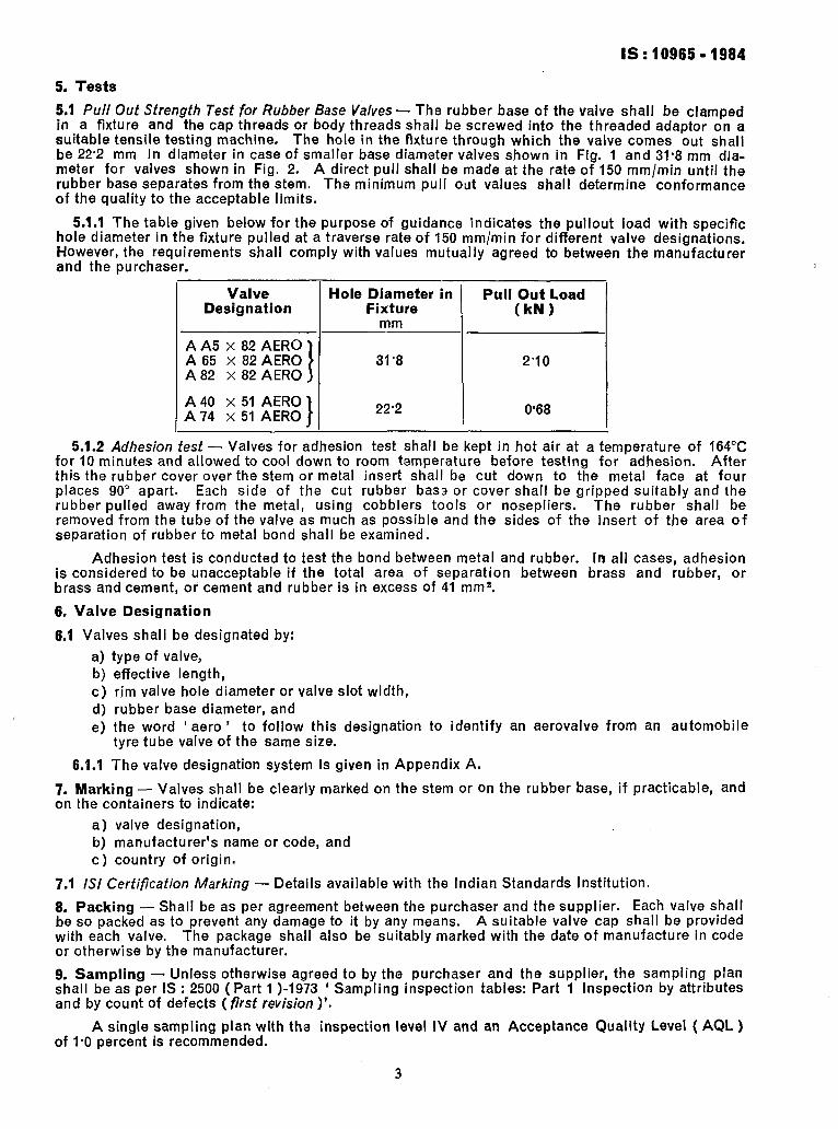
5.1.1 The table given below for the purpose of guidance indicates the pullout load with specific hole diameter in the fixture pulled at a traverse rate of 150 mm/min for different valve designations. However, the requirements shall comply with values mutually agreed to between the manufacturer and the purchaser.
Valve Designation
A A5 x 82 AERO A 65 x 82 AERO A 82 x 82 AERO
A 40 x 51 AERO A 74 x 51 AERO
Hole Diameter in Pull Out Load Fixture (kN)
mm
31’8 2’10
22’2 0.68
5.1.2 Adhesion test - Valves for adhesion test shall be kept in hot air at a temperature of 164°C for 10 minutes and allowed to cool down to room temperature before testing for adhesion. After this the rubber cover over the stem or metal insert shall be cut down to the metal face at four places 9.0” apart. Each side of the cut rubber base or cover shall be gripped suitably and the rubber pulled away from the metal, using cobblers tools or nosepliers. The rubber shall be removed from the tube of the valve as much as possible and the sides of the insert of the area of separation of rubber to metal bond shall be examined.
Adhesion test is conducted to test the bond between metal and rubber. In all cases, adhesion is considered to be unacceptable if the total area of separation between brass and rubber, or brass and cement, or cement and rubber is in excess of 41 mmB.
6, Valve Designation
6.1 Valves shall be designated by:
a) type of valve, b) effective length, c) rim valve hole diameter or valve slot width, d) rubber base diameter, and e) the word ‘ aero’ to follow this designation to identify an aerovalve from an automobile
tyre tube valve of the same size.
6.1.1 The valve designation system is given in Appendix A.
7. Marking - Valves shall be clearly marked on the stem or on the rubber base, if practicable, and on the containers to indicate:
a) valve designation, b) manufacturer’s name or code, and c) country of origin.
7.1 ISI Certification Marking - Details available with the Indian Standards Institution.
6. Packing - Shall be as per agreement between the purchaser and the supplier. Each valve shall be so packed as to prevent any damage to it by any means. A suitable valve cap shall be provided with each valve. The package shall also be suitably marked with the date of manufacture in code or otherwise by the manufacturer.
9. Sampling - Unless otherwise agreed to by the purchaser and the supplier, the sampling plan shall be as per IS : 2500 (Part 1 )-1973 ‘ Sampling inspection tables; Part 1 Inspection by attributes and by count of defects (first revision)‘.
A single sampling plan with the inspection level IV and an Acceptance Quality Level ( AQL ) of I.0 percent is recommended.
3

IS : 10965 - 1984
APPENDIX A
( Clause 6.1 .I )
AEROVALVE DESIGNATION SYSTEM
A-l. This valve designation system is based on major functional and basic dimensional character- istics. It has been developed with a prime view to help easy identification of the valves without making it too confusing and with ample scope for inclusion of new valves in the specification as and when necessary.
A-l.1 The system consists of a six digit designation followed by the suffix ‘ Aero ‘. This suffix is necessary to identify an Aircraft Tyre Tube Valve from an Automobile Tyre Tube Valve.
A-l.2 The First Digit - In the designation represents the type of the valve and shall be a Roman alphabet as follows:
A - For tube valves with rubber base, regular bore and 8Vl external threads.
A-1.3 Second and Third Digits - Represent the effective length of the valve in the straight condition ( before bending), rounded-off to the nearest millimetre. An alpha-numeral system is followed for this purpose.
Effective Length Code Effective Length Code mm mm
up to 99 Actual Value 114 64 100 A0 115 B5 101 Al 116 B6 102 A2 117 B7 103 A3 118 B8
104 A4 120 co
105 A5 130 DO
106 A6 140 EO
107 A7 150 FO
108 A8 160 GO
109 A9 170 HO
110 BO 180 JO
111 Bl 190 KO
112 B2 200 LO 113 83 210 MO
220 NO 230 PO .-A +
Note l- The code is followed in the same sequence for all sizes from 120 to 230. For example, 121 - Ct, 129- CQ, etc. I
Note 2- The alphabets ‘ I ’ and ’ 0 ’ have been excluded to avoid a mistaken identity for the numerals one and zero respectively.
A-l.4 Fourth Digit - Represents the diameter of the valve hole in the rim or width of the valve slot in the rim in numerals as fOllOWS. The data are to be given by rim manufacturers.
Hole diameter or slot width : 1, 2, 3, 4, . . . . . . . . . . . . etc.
A-l.5 Fifth and Sixth Digits - Represent the rubber base diameter of the valve and shall follow the alpha-numeral system as given in A-1.3.
EXPLANATORY NOTE
[n the preparation of this standard considerable assistance has been taken from the following publications:
a) The year book of the Tyre and Rim Association, Inc, Ohio, USA. b) IS0 4570/l-1977 Tyre valve threads : Part 1 Threads WI, 5V2, 6Vl and 8Vl. C) IS0 4570/2-1979 Tyre valve threads : Part 2 Threads 9V1, lOV2, 12Vl and 13Vl. d) IS : 9081-1979 Valves and accessories for tyre tubes for automobiles.
4
Printed at New India Printing Press, Khurla. lndla