is 11780 (1986): code for selection and testing of rotary
TRANSCRIPT

Disclosure to Promote the Right To Information
Whereas the Parliament of India has set out to provide a practical regime of right to information for citizens to secure access to information under the control of public authorities, in order to promote transparency and accountability in the working of every public authority, and whereas the attached publication of the Bureau of Indian Standards is of particular interest to the public, particularly disadvantaged communities and those engaged in the pursuit of education and knowledge, the attached public safety standard is made available to promote the timely dissemination of this information in an accurate manner to the public.
इंटरनेट मानक
“!ान $ एक न' भारत का +नम-ण”Satyanarayan Gangaram Pitroda
“Invent a New India Using Knowledge”
“प0रा1 को छोड न' 5 तरफ”Jawaharlal Nehru
“Step Out From the Old to the New”
“जान1 का अ+धकार, जी1 का अ+धकार”Mazdoor Kisan Shakti Sangathan
“The Right to Information, The Right to Live”
“!ान एक ऐसा खजाना > जो कभी च0राया नहB जा सकता है”Bhartṛhari—Nītiśatakam
“Knowledge is such a treasure which cannot be stolen”
“Invent a New India Using Knowledge”
है”ह”ह
IS 11780 (1986): Code for selection and testing of rotaryscrew air compressors (oil flooded) [MED 22: Compressor,Blowers and Exhausters]


UDC 621’514’6: 620’1 IS: 117801 1986
Indian Standard
CODE FOR SELECTION AND TESTING OF ROTARY SCREW AIR COMPRESSOR (OIL FLOODED)
1. scope - Covers the general method of selection and testing of rotary screw air compressors ( oil flooded ) up to 25 bars pressure.
2. Compressor
2.1 All equipment shall be suitable for specified operating conditions and shall work under continu- ous full load duty for at least one year.
2.2 Number of compression stages, compressor arrangement, type of drive, prime mover, free air delivery, energy consumption, coolant arrangement, etc. shall be as per agreement between the manu- facturer or the supplier and the purchaser before the order is placed.
2.3 The purchaser has to provide adequate space for erection, maintenance and operation.
2.4 In case of liquid injection system, type and characteristics of liquid shall be given to the purchaser.
2.5 Coolant characteristic, pressure and flow shall be given to the purchaser. water at suitable pressure shall be used.
If it is not given fresh Flow rates shall be specified by the manufacturer.
2.6 Critica! parts working under pressure, such as oil coolers, pressure pipes, hoses and couplings, critical castings shall be hydraulically tested at 1.5 times the operating pressure.
2.7 Studs and bolts used on compressor be heat-treated and shall conform to IS : 1367 ‘Technical supply conditions for threaded steel fasteners.’
2.7.1 All the fasteners shall be so designed that they shall not get loose during the service,
2.8 In all pipe connections, flanges are necessary for pipe size 50 mm NB and above. nection below 50 mm NB threaded connections shall be used.
In pipe con-
2.8 Rotor and shaft shall be made of one piece.
2.10 All bearings shall be of replaceable type. Radial and thrust bearings shall be adequately lubri- cated.
2.11 Lubricant seals shall be provided to prevent leakages.
2.12 Compressor rotors shall be dynamically balanced.
2.13 Name plate of the compressor shall give the following data:
a) Manufacturer’s name or trade-mark ( if any ),
b) Model designation and serial number,
c) Capacity,
d) Inlet absolute pressure,
e) Discharge absolute pressure,
f) Drive shaft speed, and
g) kW ( Horsepower ).
2.14 Direction of rotation of the compressor drive shaft shall be clearly shown by an arrow on com- pressor casing.
3. Prime Mover and Drive Equipment
3.1 Prime mover shall be sized considering transmission losses, power used for cooling fans, fric- tional losses, etc.
3.2 Electric Motor - An electric motor shall be rated for continuous output power of at least 110 percent of the maximum power required at any specified operation point, under balanced voltage conditions.
I Adopted 1 August 1966 I 0 February 1987, ISI I
Gr 2 I
I I I I INDIAN STANDARDS INSTITUTION MANAK BHAVAN, 8 BAHADUR SHAH ZAFAR MARG
NEW DELHI ltOOO2
lS:ll780- 1986
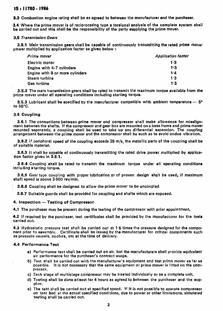
3.3 Combustion engine rating shall be as agreed to between the manufacturer and the purchaser.
3.4 Where the prime mover is of reciprocating type a torsional analysis of the complete system shall be carried out and this shall be the responsibility of the party supplying the prime mover.
3.5 Tr8nsmission Gears
3.5.1 Main transmission gears shall be capable of continuously transmitting the rated prime power multiplied by application factor as given below :
Prime mover Applicetion factor
Electric motor 113
Engine with 4-7 cylinders 1*3
Engine with 8 or more cylinders 1.4
Steam turbine 1.3
Gas turbine 1.3
mover
3.5.2 The main transmission gears shall be rated to transmit the maximum torque available from the prime mover under all operating conditions including starting torque.
3.5.3 Lubricant shall be specified by the manufacturer compatible with ambient temperature - 5’ to 55°C.
3.6 Coupling
3.6.1 The connections between prime mover and compressor shall make allowance for misalign- ment between the shafts. If the compressor and gear box are mounted on a base frame and prime mover
,mounted separately, a coupling shall be used to take up any differential expansion. The coupling arrangement between the prime mover and the compressor shall be such as to avoid undue vibration.
3.6.2 If peripheral speed of the coupling exceeds 25 m/s, the metallic parts of the coupling shall be of suitable material.
3.6.3 It shall be capable of continuously transmitting the rated drive power multiplied by applica- tion factor given in 3.5.1.
3.6.4 Coupling shall be rated to transmit the maximum torque under all operating conditions including starting torque.
3.6.5 Gear type coupling with proper lubrication or of proven design shall be used, if maximum shaft speed is above 3 600 rev/min.
: 3.6.6 Coupling shall be designed to allow the prime mover to be uncoupled.
3.6.7 Suitable guards shall be provided for coupling and shafts which are exposed.
4. Inspection - Testing of Compressor
4.1 The purchaser may be present during the testing of the compressor with prior appointment.
‘4.2 If required by the purchaser, test certificates shall be provided by the manufacturer for the tests carried out.
4.3 Hydrostatic pressure test shall be carried out at 1.5 times the pressure designed for the compo- nent prior to assembly. Certificate shall be issued by the manufacturer for critical components such as pressure vessels, coolers, etc at the time of delivery.
4.4 Performance Test
4
b)
cl 4
d
Performance test shall be carried out on air, but the manufacturers shall provide equivalent air performance for the purchaser’s contract usage,
Test shall be carried out with the manufacturer’s equipment and test prime mover as far as possible. It is not necessary that the same equipment or prime mover is fitted on the com- pressor,
Each stage of multistage compressor may be treated individually or as a complete unit,
Testing shall be done atleast for 4 hours as agreed to between the purchaser and the sup- plier,
The test shall be carried out at specified speed. If it is not possible to operate compressor on test bed at the actual specified conditions, due to power or other limitations, simulated testing shall be carried out.
2
IS: 117801. I986
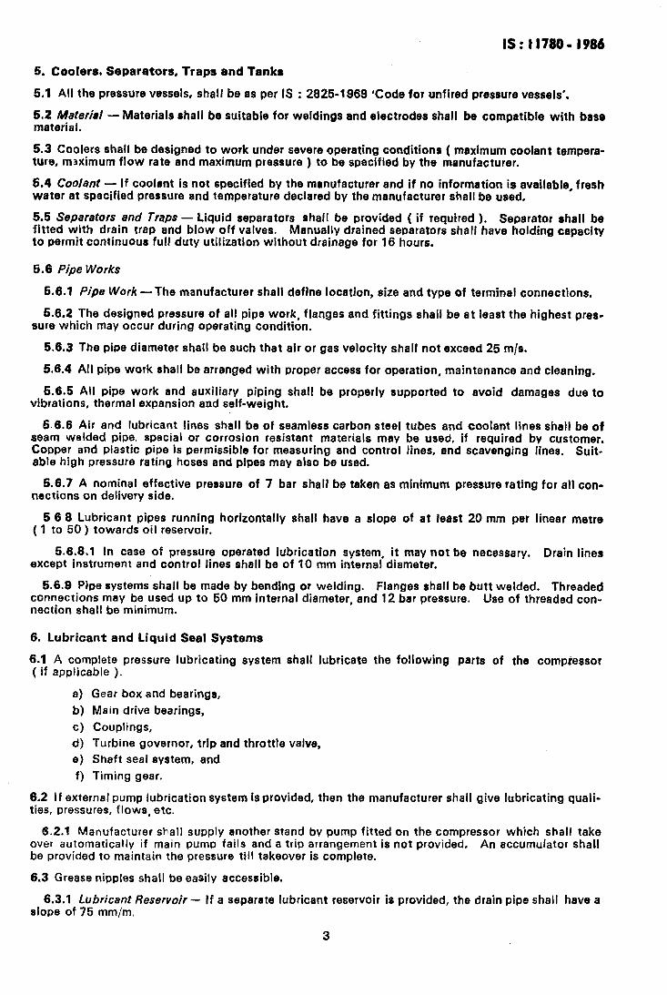
5. Coolers, Separators, Traps and Tanks
5.1 All the pressure vessels, shall be as per IS : 28251989 ‘Code for unfired pressure vessels’.
5.2 Material material.
- Materials shall be suitable for weldings and electrodes shall be compatible with base
5.3 Coolers shall be designed to work under severe operating conditions ( maximum coolant tempera- ture, maximum flow rate and maximum pressure ) to be specified by the manufacturer.
5.4 Coolant - If coolant is not specified by the manufacturer and if no information is available, fresh water at specified pressure and temperature declared by the manufacturer shall be used.
5.5 Separators and Traps - Liquid separators shall be provided ( if required ). Separator shall be fitted with drain trap and blow off valves. Manually drained separators shall have holding capacity to permit continuous full duty utilization without drainage for 16 hours.
5.8 Pipe Works
5.6.1 Pipe Work -The manufacturer shall define location, size and type of terminal connections.
56.2 The designed pressure of all pipe work, flanges and fittings shall be at least the highest pres- sure which may occur during operating condition.
5.6.3 The pipe diameter shall be such that air or gas velocity shall not exceed 25 m/s.
5.6.4 All pipe work shall be arranged with proper access for operation, maintenance and cleaning.
5.6.5 All pipe work and auxiliary piping shall be properly supported to avoid damages due to vibrations, thermal expansion and self-weight.
5.6.6 Air and lubricant lines shall be of seamless carbon steel tubes and coolant lines shall be of seam welded pipe. special or corrosion resistant materials may be used, if required by customer. Copper and plastic pipe Is permissible for measuring and control lines, and scavenging lines. Suit- able high pressure rating hoses and pipes may also be used.
5.6.7 A nominal effective pressure of 7 bar shall be taken as minimum pressure rating for all con- nections on delivery side.
6 6 8 Lubricant pipes running horizontally shall have a slope of at least 20 mm per linear metre ( 1 to 50 ) towards oil reservoir.
5.6.8.1 In case of pressure operated lubrication system, it may not be necessary. Drain lines except instrument and control lines shall be of 10 mm internal diameter.
5.6.9 Pipe systems shall be made by bending or welding. Flanges shall be butt welded. Threaded connections may be used up to 50 mm internal diameter, and 12 bar pressure. Use of threaded con- nection shall be minimum.
6. Lubricant and Liquid Seal Systems
6.1 A complete pressure lubricating system shall lubricate the following parts of the compiessor ( if applicable ).
a) Gear box and bearings,
b) Main drive bearings,
c) Couplings,
d) Turbine governor, trip and throttle valve,
e) Shaft seal system, and
f) Timing gear.
6.2 If external pump lubrication system is provided, then the manufacturer shall give lubricating quali- ties, pressures, flows, etc.
6.2.1 Manufacturer shall supply another stand by pump fitted on the compressor which shall take over automatically if main pump fails and a trip arrangement is not provided. An accumulator shall be provided to maintain the pressure till takeover is complete.
6.3 Grease nipples shall be easily accessible.
6.3.1 Lubricant Reservoir - If a separate lubricant reservoir is provided, the drain pipe shall have a slope of 75 mm/m,
3
IS : I1780 - 1986
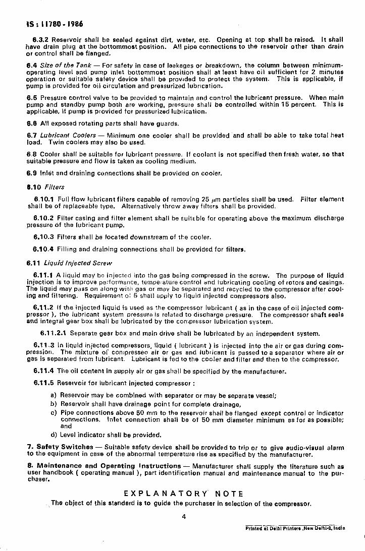
6.3.2 Reservoir shall be sealed against dirt, water, etc. Opening at top shall be raised. It shall have drain plug at the bottommost position. All pipe connections to the reservoir other than drain or control shall be flanged.
6.4 Size of the Tank - For safety in case of leakages or breakdown, the column between minimum- operating level and pump inlet bottommost position shall at least have oil sufficient for 2 minutes operation or suitable safety device shall be provided to protect the system. This is applicable, if pump is provided for oil circulation and pressurized lubrrcation.
6.5 Pressure control valve to be provided to maintain and control the lubricant pressure. When main pump and standby pump both are working, pressure shall be controlled within 15 percent. This is applicable, if pump is provided for pressurized lubrication.
6.6 All exposed rotating parts shall have guards.
6.7 Lubhmt Coolers - Minimum one cooler shall be provided and shall be able to take total heat load. Twin coolers may also be used.
6.8 Cooler shall be suitable for lubricant pressure. If coolant is not specified then fresh water, so that suitable pressure and flow is taken as cooling medium.
6.9 Inlet and draining connections shall be provided on cooler.
6.10 Filters
6.10.1 Full flow lubricant filters capable of removing 25 pm particles shall be used. Filter element shall be of replaceable type. Alternatively throw away filters shall be provided.
6.10.2 Filter casing and filter element shall be suiteble for operating above the maximum discharge pressure of the lubricant pump.
6.10.3 Filters shall be located downstream of the cooler.
6.10.4 Filling and draining connections shall be provided for filters.
6.11 Liquid Injected Screw
6.11.1 A liquid may be injected into the gas being compressed in the screw. The purpose of liquid injection is to improve performance, temperature control and lubricating cooling of rotors and casings. The liquid may pass on along with gas or may be separated and recycled to the compressor after cool- ing and filtering. Requirement oi 5 shall apply to liquid injected compressors also.
6.11.2 If the injected liquid is used as the compressor lubricant ( as in thecase of oil injected com- pressor ), the lubricant system pressure is related to discharge pressure. The compressor shaft seals and integral gear box shall be lubricated by the compressor lubrication system.
6.11.2.1 Separate gear box and main drive shall be lubricated by an independent system.
6.11.3 In liquid injected compressors, liquid ( lubricant ) is injected into the air or gas during com- pression. The mixture of compresses air or gas and lubricant is passed to a separator where air or gas is separated from lubricant. Lubricant is fed to the cooier and filter and then to the compressor.
6.11.4 The oil content in supply air or gas shall be specified by the manufacturer.
6.11.5 Reservoir for lubricant injected compressor :
a) b) cl
d)
Reservoir may be combined with separator or may be separate vessel;
Reservoir shall have drainage point for complete drainage,
Pipe connections above 50 mm to the reservoir shall be flanged except control or indicator connections. Inlet connection shall be of 50 mm diameter minimum as for as possible; and
Level indicator shall be provided.
7. Safety Switches - Suitable safety device shall be provided to trip or to give audio-visual alarm to the equipment in case of the abnormal temperature rise as specified by the manufacturer.
8. Maintenance and Operating Instructions - Manufacturer shall supply the literature such as user handbook ( operating manual ), part identification manual and maintenance manual to the pur- chaser.
EXPLANATORY‘ NOTE The object of this standard is to guide the purchaser in selection of the compressor.
4
Prlnted at Delhi Prlnterr ,New Delhi-2, lndla