is 14740 (1999): pneumatic fluid power - components using ... · used with compressible fluids...
TRANSCRIPT

Disclosure to Promote the Right To Information
Whereas the Parliament of India has set out to provide a practical regime of right to information for citizens to secure access to information under the control of public authorities, in order to promote transparency and accountability in the working of every public authority, and whereas the attached publication of the Bureau of Indian Standards is of particular interest to the public, particularly disadvantaged communities and those engaged in the pursuit of education and knowledge, the attached public safety standard is made available to promote the timely dissemination of this information in an accurate manner to the public.
इंटरनेट मानक
“!ान $ एक न' भारत का +नम-ण”Satyanarayan Gangaram Pitroda
“Invent a New India Using Knowledge”
“प0रा1 को छोड न' 5 तरफ”Jawaharlal Nehru
“Step Out From the Old to the New”
“जान1 का अ+धकार, जी1 का अ+धकार”Mazdoor Kisan Shakti Sangathan
“The Right to Information, The Right to Live”
“!ान एक ऐसा खजाना > जो कभी च0राया नहB जा सकता है”Bhartṛhari—Nītiśatakam
“Knowledge is such a treasure which cannot be stolen”
“Invent a New India Using Knowledge”
है”ह”ह
IS 14740 (1999): Pneumatic Fluid Power - Components UsingCompressible Fluids - Determination of Flow-rateCharacteristics [PGD 16: Fluid Power]


IS14740:1999 IS0 6358 : 1989
Indian Standard
PNEUMATIC FLUID POWER - COMPONENTS USING COMPRESSIBLE FLUIDS - DETERMINATION
OF FLOW-RATE CHARACTERISTICS
ICS 23.100.01
0 BIS 1999
BUREAU OF INDIAN STANDARDS MANAK BHAVAN, 9 BAHADUR SHAH ZAFAR MARG
NEW DELHI 110002
November 1999 Price Group 7
Pneumatic Fluid Power Systems Sectional Committee, PE 16
NATIONAL FOREWORD
This Indian Standard which is identical with IS0 6358 : 1989 ‘Pneumatic fluid power - Components using compressible fluids - Determination of flow-rate characteristics’ issued by the International Organization for Standardization ( IS0 ) was adopted by the Bureau of Indian Standards on the recommendation of the Pneu- matic Fluid Power Systems Sectional Committee ( PE 16 ) and approval of the Production Engineering Divi- sion Council.
In pneumatic fluid power systems, power is transmitted and controlled through a gas under pressure within a circuit. Components composing such a circuit are inherently resistive and affect the flow through it. It is, therefore, necesary to carry out tests to ascertain the characteristics of these components in order to~deter- mine their suitability. Many components composing a pneumatic circuit operate under conditions of choked flow. This standard specifies tests at choked flow in recognition of these conditions.
In the adopted standard, certain terminology, conventions and method of presentation are not identical to those used in Indian Standards. Attention is particularly drawn to thefollowing:
a) Wherever the words ‘International Standard’appear referring to this standard, they should be read as ‘Indian Standard.
b) Comma ( , ) has been used as a decimal marker while in Indian Standards the current practice is to use a point ( . ) as the decimal marker.
In this adopted standard reference appears to certain International Standards for which Indian Standards also exist. The corresponding Indian Standards which are to be substituted in their place is listed below along with their degree of equivalence for the editions indicated:
lntefnational Standard Corresponding Indian Standard
IS0 228-l : 1994 Pipe threads where pressure tight joints are not madeon the threads-Part1 : Dimensions, tolerances and designation
IS0 261 : 1998 IS0 general purpose metric screw threads - General plan
Degree of Equivalance
IS 2643 : 1975 Dimensions for pipe threads for fastening purposes : Part 1 Basic profile and dimensions, Part 2 Tolerances, Part 3 Limits of sizes
Technically Equivalent
IS 4218 ( Part 2) : 1976 IS0 metric screw do threads : Part 2 Diameter pitch combinations ( first revision )
IS0 5598 : 1985 Fluid power IS 10416 : 1992 Fluid power systems and Identical systems and components - components -Vocabulary ( first revision) vocabulary
The technical committee responsible for the preparation of this standard-has reviewed the provisions of the following IS0 standard and has decided that it is acceptable for use in conjunction with this standard:
ISO1179:1981 Pipe connections, threaded to IS0 228-l) for plain end steel and other metal tubes in industrial applications
For the purpose of deciding whether a particular requirement of this standard is complied with, the final value, observed or calculated, expressing the result of a test, shall be rounded off in accordance with IS 2 :1960 ‘Rules for rounding off numerical values (revised)‘. The number of significant places retained in the rounded off value should be the same as that of the specified value in this standard.
IS 14740 : 1999 IS0 6356 : 1969
lndian Standard
PNEUMATIC FLUID POWER - COMPONENTS USING COMPRESSIBLE
OF FLOW-RATE FLUIDS - DETERMINATION CHARACTERISTICS
1 Scope
This International Standard specifies a method for testing pneumatic fluid power components which use compressible fluids, i.e. gases, to enable their flow-rate characteristics under steadv-state conditions to be compared.
It specifies requirements for the test installation, the test pro- cedure and the presentation of results.
Accuracy of measurement is divided into two classes (A and B) which are explained in annex A.
General background information is given in annex B and the basic theoretical equations are given in annex C. Guidance as to the use of practical units for the presentation of results is given in annex D.
This International Standard generally applies to those fluid power components up to and including 20 mm nominal bore used with compressible fluids (gases), the internal flow passages of which remain constant during testing. Examples of such components are
a) directional control valves, flow control valves, quick exhaust valves, etc. ;
b) moving part logic devices.
It ay also apply to components larger than 20 mm nominal “a bore ut this may require the provision of exceptionally large
flow generating equipment.
Two test methods are~described according to the type of com- ponent. There are also two sets of characteristic constants : C and b; and A and s, respectively (as defined in 3.2 to 3.5). These may be calculated from the results.
The first set of characteristics (C and b) applies to cases where comparison of similar components is required, or when calcu- lations of pressure and flow involve a single component only.
The second set of characteristics (A and s) is necessary when the flow behaviour of several components which are con- nected in series is to be estimated. This set may also be used as an optional alternative to the first set for simple flow calcu- lations and for comparison of components.
This International Standard does not apply to components which exchange energy with the fluid (gas), for example cylinders, accumulators, etc.
2 Normative references
The following standards contain provisions which, through reference in this text, constitute provisions of this International Standard. At the time of publication, the editions indicated were valid. All standards are subject to revision, and parties to agreements based on this International Standard are encouraged to investigate the possibility of applying the most recent editions of the standards listed below. Members of IEC and IS0 main- tain registers of currently valid International Standards.
IS0 228-l : 1982, Pipe threads where pressure-tight hints are not made on the threads - Part 1: Designation, dimensions and tolerances.
IS0 261 : 1973. IS0 general purpose metric screw threads - General plan.
IS0 1179 : 1961, Pipe connections, threaded to IS0 228- 1, for plain end steel and other metal tubes in industrial applications.
IS0 5596 : 1985, Fluid power systems and components - Vocabulary,
3 Definitions
For the purposes of this International Standard, the definitions given in IS0 5598 and the following definitions apply. It should be ~borne in mind, however, that the following definitions may differ from those given in other specific International Standards.
3.1 choked flow: Occurrence when upstream pressure, pl, is high in relation to the downstream pressure, ~2, such that the velocity in some part of the component becomes sonic. The mass flow of the gas is proportional to the upstream pressure, pl, and independent of the downstream pressure, p2.
3.2 cr2tical pressure ratio, b: Pressure ratio @2/p,) below which flow becomes choked.
3.3 sonic conductance, C: Mass flow rate through the component, q;, divided by the product of the upstream
1
IS 14740 : 1999 IS0 6356 : 1969
pressure, pl, and the mass density at standard conditions ~0 (see table 2) when the flow is choked, I.e.
4% c=_ atT= To eo PI
NOTE - The numerical value of C depends upon the values chosen for the standard reference atmosphere.
3.4 coefficient of compressibility effect, s: Coefficient which takes into account the effects of the gas compressibility when flow is subsonic (see 0.2.3).
3.5 effective area, A : Mass flow rate throughout the com- ponent, q,,,, divided by the squareroot of twice the product of the pressure drop, Ap. and the mass density of the gas ~2, i.e.
A= Qm
JZGG
This applies only when the pressure drop is small in relation to p1 such that compressibility effects are insignificant, i.e. when ApIp, < g,g2.
4 Symbols and units
4.1 The symbols and units used throughout this International Standard are as shown in table 1.
Table 1 - Symbols and units
efer- Description Sym- bol Dimensiont) SI
Nnce units21
3.5 Effective area A L2 m2
3.2 Critical pressure ratio b pure number
3.3 Sonic conductance C L”TM -1 s.m4/kg
- Absolute static pressure (equal to the relative static pressure plus the atmospheric pressure) P ML-‘T-2 Pa31
- Mass flow rate Qm MT-’ kg/s
- Volume flow rate at standard conditions Qv L3T-1 m3/s
- Gas constant (for a perfect gas) R L2T-20-l J/fkg.KI
3.4 Coefficient of com- pressibility effect s pure number
- Absolute temperature T 0 K
- Pressure drop (~1 - ~2) Ap ML-‘T-2 Pa31
- amass density Q ML-3 kg/m3
1) M = mass; L = length ; T = time; 0 = temperature
2) The use of practical units for the presentation of results is described in annex D.
3) 1 Pa = 1 N/m2
4.2 The numerals used as subscripts and the asterisk (“1 used as a suRerscript to the symbols listed in table 1 are as specified in table 2.
Table 2 - Subscripts and superscripts
Super- Sub- script script Meaning
0 Standard reference conditions, i.e. : To = 293,15 K; po = 100 kPa (1 barth 65 % relative humidity
1 Upstream conditions
2 Downstream conditions
l Conditions during sonic flow tests
1) 1 bar = 166 kPa = 0,l MPa; 1 Pa = 1 N/m2
4.3 The graphical symbols used in figures 1 and 2 are in ac- cordance with IS0 1219.
5 Test installation
5.1 Test circuit for components with inlet and
outlet ports
A suitable test circuit as shown in figure 1 shall be used.
5.2 Test circuit for components which exhaust directly to atmosphere
A suitable test circuit as shown in figure 2 shall be used.
NOTE - Figures 1 and 2 illustrate basic circuits which do not incor- porate all the safety devices necessary to protect against damage in the event of component failure. It is important that those responsible for carrying out the test give due consideration to safeguarding both per- sonnel and equipment.
5.3 General requirements
5.3.1 The test components shall be installed and operated in the test circuit inaccordance with the manufacturer’s operating instructions.
5.3.2 A filter shall be installed which provides a standard of filtration approved by the test component manufacturer.
5.3.3 A test set-up shall be constructed from the items listed in table 3.
NOTE - Items A to H inclusive are essential and the remaining items I to L are chosen by the experimenter to suit the prevailing conditions.
2

A B c v D F G H K L
Figure 1 - Test circuit for components with irilet and outlet ports ‘)
I
E
- >
c
I >lOd, IOd,
B c L D F
Figure 2 - Test circuit for components which exhaust directly to atmosphere ‘)
0 1) See table 3 for key to circuit items.

IS 14740: 1999 IS0 6356 : 1969
Table 3 - Key to test circuit components
Reference Relevant
letter sub- Description Comments clause(s)
A 53.2 6.1.1.2
Compressed gas source and filter
B - Adjustable pressure regulator
C - Shut-off valve Preferably with straight flow path
D 5.4 Temperature-measuring tube
E - Temperature-measuring instrument Sensor located on axis of D at a distance 3d3 upstream of end of D
F 5.5 Upstream pressure-measuring tube
G - Component under test
H 5.5 Downstream pressure-measuring tube
I - Upstream pressure gauge or transducer
J - Differential pressure gauge or When Ap > 100 kPs (1 bar), this transducer gauge may be replaced by a
downstream pressure gauge or transducer
K
L
- Flow-control valve To have a flow-rate capacity greater than the component under test
- Flow-rate measuring device May also be placed in position L’ upstream of D
5.3.4 All connections for pressure measurement shall be
arranged in such a manner that no trap can form or retain 5.6 Special requirements
entrained liquid ; a drain may be provided.
5.4 Temperature-measuring tube (item Dl
A tube shall be provided with an internal diameter, ds, which is not less than three times the internal diameter, dt , of the inlet pressure-measuring tube (item F) and with a length not less than ten times its internal diameter, ds.
5.6 Pressure-measuring tubes (items F and HI
5.5.1 Tubes which conform with figure 3 shall be provided. Typical dimensions of the pressure-measuring tubes are also stated in table 4.
The tube shall be straight with a smooth, circular internal sur- face, and a constant diameter throughout its length.
There shall be no obstruction or branch connection other than those specified.
5.5.2 One~or more pressure-tapping holes shall be provided in accordance with figure 3.
The longitudinal centreline of the tube shall intersect with the centrelines of the holes and the centrelines of the holes shall be normal to the longitudinal centreline.
The junction of each hole with the internal surface of the tube Periodically check that the pressure-tapping holes are not shall be sharp edged and free from burrs. blocked by liquids or solid particles.
5.6.1 When the component under test has ports which are not threaded~and other means of connecting to pipes or hoses are used, measuring tubes having internal diameters which cor- respond to the appropriate pipe or hose internal diameters shall be used.
5.6.2 If these diameters do not correspond, measuring tubes of the next largest internal diameter in the range shall be used.
5.6.3 When the component under test has ports which differ in size, measuring tubes which are suited to the relevant port shall be used.
6 Test procedures
5.1 Test conditions
6.1.1 Gas supply
6.1.1.1 The gas used shall be stated in the test report.
6.1.1.2 The~gas shall be filtered and conditioned to comply with the recommendations of the test component manufac- turer.
6.1.2 Checks
4


IS 14740 : 1999 IS0 6356 : 1969
6.1.3 Test measurements
6.1.3.1 Each set of test readings shall be recorded after steady-state conditions have been reached.
6.1.3.2 The variations in upstream parameters shall be within the tolerances stated in table 5.
Table 5 - Permissible variations in indicated values of upstream parameters
riizl7 ~~~ Class of measurement accuracy I A I 0 I
IVariation in temperature indication, K I *‘I -I
1 Variation in pressure indication, % I *‘I *21
Variation in flow rate indication, % 6.2.1.7 Repeat the steps described in 6.2.1.4, 6.2.1.5 and 6.2.1.6 with q,,, equal to 50 %, 40 % and 20 %~of qn.
6.2.2 Component exhausting directly to atmosphere
6.1.3.3 Maintain flow conditions constant in each flow path within the component while taking measurements to ensure there is no inadvertent movement of component parts.
6.2.2.1 Measure atmospheric pressure, ~2, and temperature, To, and set the upstream pressure, pl, to approximately 10 kPa (0,l bar) higher than ~2.
6.2 Measuring procedure
According to the design of the component under test, either of the procedures described in 6.2.1 or 6.2.2 shall be followed.
6.2.22 Measure the mass flow rate, q,n, temperature, T, and upstream pressure, pl.
6.2.2.3 Set the upstream pressure successively at approxi- mately 150 kPa (1.5 bar), 300 kPa (3 bar), 500 kPa (5 bar), etc., and repeat the step described in 6.2.2.2.
6.2.1 Component with upstream and downstream measuring tubes 6.2.2.4 Compute values for qm mo and plot them against
pl, as shown in figure 4.
6.2.1.1 Maintain a constant upstream pressure, pl, of not less NOTE - Choked flow is indicated when the plotted points are found to than 400 kPa (4 bar) and preferably higher. lie on a straight line directed from the origin.
6.2.1.2 Decrease the downstream pressure, ~2, using the flow control valve K, until a further decrease no longer pro- duces an increase in the mass flow rate, q,n; this is the indi- cation of choked flow.
6.2.1.3 Measure temperature, T*, upstream -pressure, pr, mass flow rate, qk, and downstream pressure, pz..
6.2.1.4 Partly close the flow control valve K to reduce the mass flow rate, qm, to approximately 80 % of qil.
6.2.1.5 Adjust the pressure regulator 0 as required to main- tain p1 at a constant value throughout the test.
6.2.1.6 Measure the flow rate, q,,,, temperature, 7, and pressure differential, hp.
Subsonic flow 4
-I Choked flow ~
Figure 4 - Plot of mass flow rate against upstream pressure
6

IS 14740 : 1999 IS0 6356 : 1969
6.3 Calculation of characteristics 6.3.4 Effective area, A
6.3.1 Sonic conductance, C
Calculate the sonic conductance from the following equation :
9; CC--..-- G
eo P; J r,
Calculate the effective area from the following equation:
A = C&y,dm;
NOTE - If, when testing a component in accordance with 6.2.2, it is found that choked flow is not reached, the effective area A may be calculated from the equation defined in 3.5.
where T; is the value of T measured while the flow is choked.
7 Presentation of test results 6.3.2 Critical pressure ratio, b
6.3.2.1 If the upstream temperature remained constant during the test, calculate the value of b, for each value of q,n, from the following simplified equation :
AP
b=l- Pl
6.3.2.2 If variations in pr and T occurred during the test, calculate the value of b, for each value of q,,,, from the follow- ing equation :
AP -
b=l- PI
‘- 1/1-(&Q 6.3.2.3 Calculate the critical pressure ratio as the mean value of b, for each value of q,,,, calculated in accordance with either 6.3.2.1 or 6.3.2.2.
6.3.2.4 Calculate the ratio p$lpi . If this ratio is greater than the critical ratio b, retest with lower values of p2 or higher values of p1 to ensure that choked flow has been achieved.
6.3.3 Coefficient of compressibility effect, s
Calculate the coefficient of compressibility effect from the following equation :
1 s=- 1 -b
7.1 All measurements and the results of calculations shall be tabulated by the testing agency and, where specified or when appropriate, shall also be presented graphically as described in 6.2.2.4.
7.2 The following performance characteristics related to flow-rate capacity and flow, which are calculated in accordance with 6.3, shall be stated ; from these characteristics the per- formance of the component can be predicted and compared, either in the form a) and b), or the form a) or b) :
a) sonic conductance, C, and critical pressure ratio, b;
NOTE - Parameters C and b will be valid only for the gas used in the test.
b) ~effective area, A, and coefficient of compressibility effect, s.
NOTE - Parameter s will also be valid only for the gas used in the test.
7.3 The class of measurement accuracy, i.e. A or B from annex A, shall be stated and the calibration record shall be available.
8 Identification statement (Reference to this International Standard)
Use the following statement in test reports, catalogues and sales literature when electing to comply with this International Standard :
“Test for the determination of flow-rate characteristics con- forms to IS0 6366. Pneumatic fluid power - Components using compressible fluids - Determination of flow-rate characteristics. ‘*
7

IS 14740 : 1999 IS0 6358 : 1989 4
Annex A (normative)
Errors and classes of measurement accuracy
NOTE - The contents of this annex are under review and may besubject to amendment in the future.
A.1 Classes of measurement accuracy
Depending on the accuracy required, the tests shall be carried out to one of two classes of measurement, A or B.
The class of measurement accuracy shall be stated.
NOTES
1 Class A is intended for special cases when there is a need to have the performances more preciseiv defined.
2 Attention is drawn to the fact that class A tests require more ac- curate apparatus and methods, which increase the costs of such tests.
A.2 Errors
Any device or method shall be used which, by calibration or comparison with International Standards, has been proven to be capable of measuring with systematic errors not exceeding ‘the limits given in table A.l.
NOTE - The percentage limits given in table A.1 apply to the value of the quantity being measured and not to the maximum values of the test or the maximum reading of the instrument.
Table A.1 - Permissible systematic errors of measuring
instruments as determined during calibration
Permissible systematic Parameter of errors for classes of
measuring instrument measurement accuracy
A B
Flow rate, % f2 f4
Pressure, % fl f2
Temperature, K fl f2
A.3 Combination of errors
When an end result is calculated from several measurements, the combination of errors involved in that result may be deter- mined by the root mean square method.
EXAMPLE
In this simplified method
c= Qlm
eo
The systematic errors used above, hq,,,, Sp and 6T,, are the actual systematic errors of the instruments and not the maxi- mum values given in table A. 1. For more precise summation of errors refer to Vocabulary of legai metrology - Fundamental terms published by the International Organization of Legal Metrology.
A.4 Expected variations
The method given in A.3 may give variations of up to f 15 % on results due to deviations in repeatability and in laboratory conditions.

IS 14740 : 1999 IS0 6358 : 1989
Annex B (informative)
General information
B.l When, for constant abSo&te upstream pressure and
temperature, the mass flow rate of compressible fluid through
a component is measured as a function of the ratio of the
downstream and upstream pressures, and the data points are plotted, a typical graph as in figure B.l is obtained.
4, 4
Gas and upstream conditions fixed
El El
*a
El
El
El
” t
0 -i P2JPl
Figure 6.1 - Typical representation of mass flow rate against pressure ratio ”
1) The rectangles represent the measurement uncertainty.
9

IS 14740 : 1999 IS0 6358 : 1989
6.2 The results are more useful if an analytical curve is fitted through the points and if the coefficients are related to the upstream conditions and the nature of the gas. The accuracy of the representation becomes better when the number of independent coefficients used increases, but the diiiculty of use also increases.
8.3 Using a simplified model of the components and the general laws of thermodynamics, it is possible to derive adequate theoretical equations for such a curve using only two
independent coefficients. After calculating the coefficients from experimental data, the curves may be fitted to the points plotted from the graph.
It has been shown that when the velocity at some part of a pneumatic component becomes sonic, the flow remains nearly constant with constant upstream pressure and when the velocity is smaller, the curve qm = f (p2/pj) is nearly elliptical. The general representation used in this International Standard is given in figure 8.2.
Function of C, pl, T,
pl and T, are
i
I I
Function of A. s, ~1, T1
l- 0 bor (I- b’ i P2/Pl
Choked flow Subsonic flow D
NOTE - Choking usually occurs at the outlet; in cases where the Choking throat lies within the component and there is also a significant pressure drop between the throat and the point of measuring p2, the curve is distorted as indicated by the thick dashed line.
Figure 8.2 - General presentation of mass flow rate against pressure ratio
10
IS 14740 : 1999 IS0 6358 -: 1989
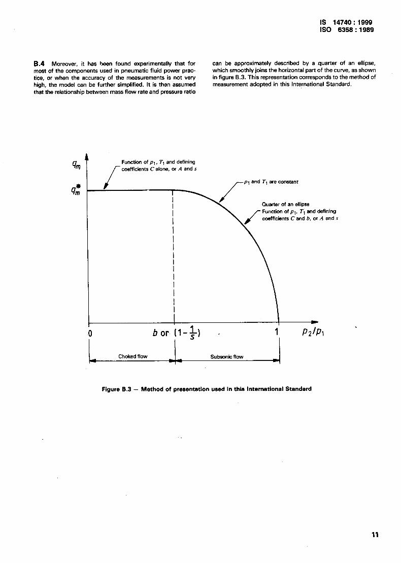
8.4 Moreover, it has been found experimentally that for most of the components used in pneumatic fluid power prac- tice, or when the accuracy of the measurements is not very high, the model can be further simplified. It is then assumed that the relationship between mass flow rate and pressure ratio
can be approximately described by a quarter of an ellipse, which smoothly joins the horizontal part of the curve, as shown in figure 8.3. This representation corresponds to the method of measurement adopted in this International Standard.
Function of pt , T1 and defining coefficients C alone, or A and s
bor (I- 1 I72471
Choked flow Subsonic flow -0 )
Figure 8.3 - Method of presentation used in this International Standard
11

-1s 14740 : 1999 iso 6356 : 1969
Annex C (informative)
Basic theoretical equations
The flow performance of a compressible fluid component is completely described, by either of two equivalent groups of equations, each using two independent constant parameters.
Group 2 equations
- For choked flow, i.e. when Aplp, > l/s,
Group 1 equations
- For choked flow, i.e. whenp21p, < b, q;=Ax Ax+
qf= CP,@fJ d TO - *1
- For subsonic flow, i.e. when p2fp, > b,
This last equation may also be written as follows:
f++=Wb+-/~
- For subsonic flow, i.e. when Aplp, < l/s.
qm
This last equation may also be written as follows:
AP 1 -=- Pl s
{l -/_I]
12

IS 14740 : 1999 IS0 6358 : 1989
Annex D (informative)
Use of practical units
D.l Practical units
The results of the test may be presented in either tabular or graphical form using the practical units as given in table D. 1.
Table D.1 - Practical units
Quantity
Effective area
Critical pressure ratio
Sonic conductance
Absolute static pressure
Mass flow rate
Volume flow rate at standard conditions
Gas constant
Coefficient of compressibility effect
Absolute temperature
Pressure drop (pl - ~2)
Mass density
‘1 1 bar = 105 Pa = 105 N/m2
-r Symbol
A
b
c
P
qm
qv
R
s
T
AP
e
Practical unit
mm2
-
dm3/(s.kPaI
dm3/(zlbarl”)
kPa (bar)
91s
dm3/s (ANRI
J/(kg.K)
-
K
kPa (bar1
g’ldm3
J
0.2 Calculations
In order to present results in practical units as given in table D. 1 and using volumetric gas flow rate, the formulae given in this International Standard shall be modified as follows :
D.2.1 Sonic conductance (see 6.3.1). in cubic deci- metres per second kilopascal or decimetres per second bar
c-q; ” p; lr TO
at standard conditions
D.2.2 ’ Critical pressure ratio (see 6.3.2)
hP
b=l- l-JT&y or if upstream conditions T and p1 remain constant during the test, the calculation may be simplified as follows :
AP 7i;
b=l-
l-
D.2.3 Coefficient of compressibility effect (see 6.3.3)
1 ,.j=-
l-b
D.2.4 Effective area (see 6.3.41, in square millimetres
A = 3,442Cvy
for air only
D.2.5 Gas constant (for a perfect gas), in joules per kilogram kelvin
R = 266
for air only l)
D.2.6 Mass density at standard conditions, in grams per cubic decimetre
@o = 1,185
for air only’)
D.2.7 Basic’theoretical equations (see annex Cl
D.2.7.1 Group 1 equations may be used as written with prac- tical units.
D.2.7.2 To use the group 2 equations, replace A by 100 A to convert them to use with practical units.
1) At standard atmosphere, i.e. TO = 293,15 K, 65 % relative humidity, po = 100 kPa (1 bar).

dls 14740 : 1999 IS0 6358:1989
Annex E (informative)
Bibliography
IS0 1219 : 1976, Fluid power systems and components - Graphic symbols.
14
Bureau of Indian Standards
BIS is a statutory institutionestablished under the Bureau oflndian StandardsAct, 1986 to promote harmonious development of the activities of standardization, marking and quality certification of gaods and attending to connected matters in the country.
Copyright
BIS has the copyright of all its publications. No part of these publications may be reproduced in any form without the prior permission in writing of BIS. This does not preclude the free use, in the course of implementing the standard, of necessary details, such as symbols and sizes, type or grade designations. Enquiries relating to copyright be addressed to the Director (Publications), BIS.
Review of Indian Standards
Amendments are issued to standards as the need arises on the basis of comments. Standards are also reviewed periodically; a standard along with amendments is reaffirmed when such review indicates that no changes are needed; if the review indicates that changes are needed, it is taken up for revision. Users of Indian Standards should ascertain that they are in possession of the latest amendments or edition by referring to the latest issue of ‘BlS Handbook’ and ‘Standards : Monthly Additions’.
This Indian Standard has been developed from Dot : No. PE 16 -( 0220 >.
Amendments Issued Since Publication
Amend No. Date of Issue Text Affected
Headquarters:
BUREAU OF INDIAN STANDARDS
Mauak Bhavan, 9 Bahadur Shah Zafar Marg, New Delhi 110002 Telephones : 323 01 31,323 94 02, 323 33 75
Telegrams: Manaksanstha ( Common to
all offices )
Regional Offices: Telephone
Central : Manak Bhavan, 9 Bahadur Shah Zafar Marg 32376 17 NEW DELHI 110002 323 384:
Eastern : l/14 C. I. T. Scheme VII M, V. I. P. Road, Maniktola I 337 84 99, 337 85 6: CALCUTTA 700054 337 86 26,337 86 62
Northern : SC0 335-336, Sector 34-A, CHANDIGARH 160022 -I 60 38 43 60 20 25
’ Southern : C. I. T. Campus, IV Cross Road, CHENNAI 600113 { 23502 16,2350442 235 15 19,235 23 15
Western : Manakalaya, E9 MIDC, Mar& Andheri (East) MUMBAI 400093
1 8329295,8327858 8327891,8327892
Branches : AHMADABAD. BANGALORE. BHOPAL. BHUBANESHWAR. CGIMBATORE. FARIDABAD. GHAZIABAD. GUWAHATI. HYDERABAD. JAIPUR. KANPUR. LUCKNOW. NAGPUR. PATNA. PUNE. THIRUVANANTHAPURAM.
hinted at New India Printing Press, Khurja, India