is 15728 (2006): welding - friction welding of metallic ... · en 1711 non-destructive examination...
TRANSCRIPT

Disclosure to Promote the Right To Information
Whereas the Parliament of India has set out to provide a practical regime of right to information for citizens to secure access to information under the control of public authorities, in order to promote transparency and accountability in the working of every public authority, and whereas the attached publication of the Bureau of Indian Standards is of particular interest to the public, particularly disadvantaged communities and those engaged in the pursuit of education and knowledge, the attached public safety standard is made available to promote the timely dissemination of this information in an accurate manner to the public.
इंटरनेट मानक
“!ान $ एक न' भारत का +नम-ण”Satyanarayan Gangaram Pitroda
“Invent a New India Using Knowledge”
“प0रा1 को छोड न' 5 तरफ”Jawaharlal Nehru
“Step Out From the Old to the New”
“जान1 का अ+धकार, जी1 का अ+धकार”Mazdoor Kisan Shakti Sangathan
“The Right to Information, The Right to Live”
“!ान एक ऐसा खजाना > जो कभी च0राया नहB जा सकता है”Bhartṛhari—Nītiśatakam
“Knowledge is such a treasure which cannot be stolen”
“Invent a New India Using Knowledge”
है”ह”ह
IS 15728 (2006): Welding - Friction welding of metallicmaterials [MTD 12: Welding Applications]


IS15728:2006ISO15620:2000
Indian Standard
WELDING — FRICTION WELDING OFMETALLIC MATERIALS
iCS 25.160,’IC)
@ 61S 2006
BUREAU OF INDIAN STANDARDSMANAK BHAVAN, 9 13AHADUR SHAH ZAFAR MARG
NEW DELHI 110002
December 2006 Price Group 11

Welding Applications Sectional Committee, MTD 12
NATIONAL FOREWORD
This Indian Standard which is identical with ISO 15620:2000 ‘Welding — Friction welding of metallic materials’issued by the International Organization for Standardization (ISO) was adopted by the Bureau of IndianStandards on the recommendation of the Welding Applications Sectional Committee and approval of theMetallurgical Engineering Division Council.
The text of ISO Standard has been approved as suitable for publication as an Indian Standard withoutdeviations. Certain conventions are, however, not identical to those used in Indian Standards. Attention isparticularly drawn to the following:
a) Wherever the words ‘International Standard’ appear referring to this standard, they should be readas ‘Indian Standard’.
b) Comma (,) has been used as a decimal marker while in Indian Standards, the current practice is touse a point (.) as the decimal marker.
In this adopted standard, reference appears to the following International Standard for which Indian Standardalso exists. The corresponding Indian Standard which is to be substituted in its place is listed below alongwith its degree of equivalence for the edition indicated:
International Standard Corresponding Indian Standard Degree of Equivalence
EN 1290 Non-destructive examination IS 5334:2003 Code of practice for Technically’ Equivalentof welds — Magnetic particle magnetic particle flaw detection of
examination of welds welds (first revision)
In this adopted standard, reference also appears to the following International Standard for which no IndianStandard exists:
International Standard Title
EN 1289 Non-destructive examination of welds — Penetrant testing of welds —Acceptance levels
EN 1711 Non-destructive examination of welds — Eddy current examination of welds bycomplex plane analysis
EN ISO 4063 Welding and allied processes — Nomenclature of processes and referencenumbers (ISO 4063: 1998)
In reporting the results of a test or analysis, made in accordance with this standard, if the final value,observed or calculated, is to be rounded off, it shall be done in accordance with IS 2 : 1960 ‘Rules forrounding off numerical values (revised)’.

IS 15728:2006ISO 15620:2000
Indian Standard
WELDING — FRICTION WELDING OFMETALLIC MATERIALS
1 Scope
This standard specifies requirements for the friction welding of components manufactured from metals.
It specifies requirements particular to rotational friction welding related to welding knowledge, quality requirements,welding procedure specification, welding procedure approval and welding personnel.
This standard is appropriate where a contract, an application standard or regulatory requirement requires thedemonstration of the manufacturer’ s capability to produce welded constructions of a specified quality. It has beenprepared in a comprehensive manner to be used as a reference in contracts. The requirements given maybeadopted in full or some may be deleted, if not relevant to the construction concerned.
2 Normative references
This European Standard incorporates by dated or undated reference, provisions from other publications. Thesenormative references are cited at the appropriate places in the text and the publications are listed hereafter. Fordated references, subsequent amendments to or revisions of any of these publications apply to this EuropeanStandard only when incorporated in it by amendment or revision. For undated references the latest edition of the
publication referred to applies (including amendments).
EN 1289Non-destructive examination of welds – Penetrant testing of welds - Acceptance levels
EN 1290Non-destructive examination of welds - Magnetic particle examination of welds
EN 1711Non-destructive examination of welds – Eddy current examination of welds by complex plane analysis
EN ISO 4063Welding and allied processes - Nomenclature of processes and reference numbers (ISO 4063:1 998)
3 Terms and definitions
For the purposes of this standard, the following terms and definitions apply.
3.1axial forceAxial force between components to be welded.
3.2axial pressurePressure (force per unit area) on the faying surfaces.
3.3burn-off lengthLoss of length in the friction phase.
3.4burn-off rateThe rate of shortening of the components during application of the friction force.
3.5componentA single item before welding.
3.6component induced brakingReduction in rotational speed resulting from friction between the interfaces.
3,7contact forceAxial force on contact of components.

IS 15728:2006ISO 15620:2000
3.8contact torqueReaction torque after friction start
3.9external brakingExternal braking reducing the rotational speed.
3.10faying surfaceA surface of one component that is to be in contact with a surface of another component to form a joint.
3.11forge forceThe force applied normal to the faying surfaces at the time when relative movement between the components isceasing or has ceased.
3.12forge lengthThe amount by which the overall length cf the components is reduced during the application of the forge force.
3.13forge phaseIn the friction welding cycle the interval between the start and finish of application of the forge force.
3.14
forge pressureThe pressure (force per unit area) on the faying surfaces resulting from the axial forge fOrCe.
3.15forge rateThe rate of shortening of the components during the application of forge force.
3.16forge timeThe time for which the forge force is applied to the components.
3.17friction force(s)The force(s) applied normal to the faying surfaces during the time that there is relative movement between thecomponents.
3.18friction phaseIn the friction welding cycle the interval in which the heat necessary for making a weld is generated by relativemotion and the friction force(s) between the components, i.e. from contact of components to the start ofdeceleration.
3.19friction pressure(s)The pressure(s) (force per unit area) on the faying surfaces resulting from the axial friction force.
3.20friction timeThe time during which relative movement between the components takes place at rotational speed and underapplication of the friction force(s).
3.21interfaceThe contact area developed between the faying surfaces after completion of the welding operation.
3.22length allowanceExtra material to allow for loss of length
3.23c>verhangTtv? ,~lstance a component projects from the fixture, or chuck irl the direction of the mating component.
IS 15728:20061S0 15620:2000
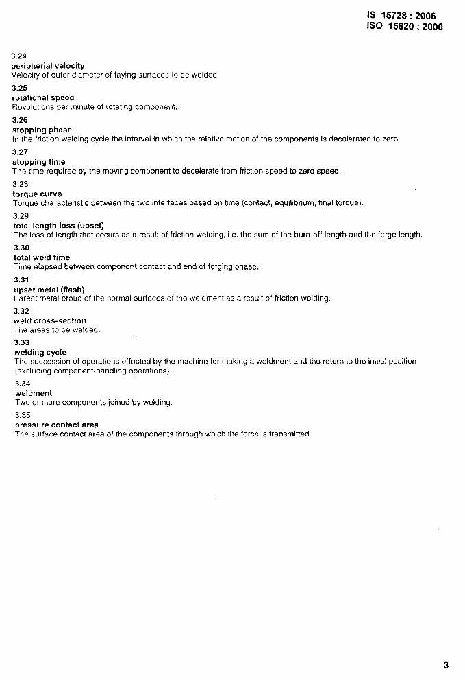
3.24peripheral velocityVelocity of outer diameter of faying surfaces to be welded
3.25rotational speedRevolutions per minute of rotating component
3.26stopping phaseIn the friction welding cycle the interval in which the relative motion of the components is decelerated to zero.
3.27stopping timeThe time required by the moving component to decelerate from friction speed to zero speed.
3.28torque curveTorque characteristic between the two interfaces based on time (contact, equilibrium, final torque).
3.29total length loss (upset)The loss of length that occurs as a result of friction welding, i.e. the sum of the burn-off length and the forge length.
3.30total weld timeTime elapsed between component contact and end of forging phase,
3.31upset metal (flash)Parent metal proud of the normal surfaces of the weldment as a result of friction welding
3.32weld cross-sectionThe areas to be welded
3.33welding cycleThe succession of operations effected by the machine for making a weldment and the return to the initial position(excluding component-handling operations).
3.34weldmentTwo or more components joined by welding.
3.35pressure contact area“The surface contact area of the components through which the force is transmitted.
3

IS 15728:2006ISO 15620:2000
4 Welding knowledge
4.1 Process
The classification of friction welding processes are listed in table 1.
Table 1- Classification of friction welding processes
I Friction welding I
I
I Relative motia classification I Energy classification III
I 1
Continuous drive I Stored enerqv
The process variant wherepower or energy is provi-ded by an infinite durationsource and maintained fora preset period
The process variant wherethe energy for welding issupplied by the kineticenergy stored in a rotatingsystem or fluid storagesvstem
I 1I,
Hvbrid svstem
Combining some features of both methods
Rotational Linear Angularreciprocation oscillation
A method in which one A method in which one A method in which onecomponent is rotated rela- component is moved in a component is moved in antive to and in contact with linear oscillating motion angular oscillating motionthe mating face of another relative to and in contact about a common compo-component or components. with the mating face of nent axis relative to and in
another component. contact with the matingface of another compo-
1 nent.I
0 0
Orbital
A method in which onecomponent is moved in asmall circular motion rela-tive to and in contact withthe mating face of anothercomponent.
O@
4

4.1.1 Direct drive rotational
The energy input is provided by
IS 15728:ISO 15620
friction welding
direct drive at predetermined rotational speed or speeds, figures 1 and 2
(D1 Drive motor2 Brake3a Rotating clamp3b Stationary clamp4a Rotating workpiece4b Stationary workpiece5 FGrge cylinder
A - ~-y-- L. -m
.\/ : ‘ n. r
Figure 1- Diagram showing direct drive rotational friction welding
I
1 Axial force 1) Burn-off length2 Axial displacement 2j Friction time3 Rotational speed 3) Stopping time4 Friction phase 4) Forge time5 Friction force 5) Forge length6 Stopping phase 6) Total length loss (upset)7 Forge phase8 Forge force
Figure 2- Diagram showing typical relationships of characteristics for friction welding at constantrotational speed (friction welding, process No. 42 in accordance with EN ISO 4063)
The spindle is either decelerated at a predetermined rate or stopped by external braking or component inducedbraking, The main welding parameters are listed below and their relationship is given in Annex A:
– rotational speed(s);– predetermined friction force(s);- friction time or burn~off;-- predetermined forge force(s);– forge time;– stopping time and forge delay.
2006:2000
5

IS 15728:2006ISO 15620:2000
4.1.2 Stored energy (inertia) friction welding
Energy stored in an inertia mass is used up in the friction welding process by component induced braking, seefigures 3 and 4.
123a3b4a4b5
1234567
Drive motorInertia mass, variableRotating clampStationary clampRotating workpieceStationary workpieceForge cylinder
Figure 3- Diagram showing inertia friction welding
Axial force 1) Total length loss (upset)Axial displacement 2) Friction timeRotational speed 3) Forge timeFriction phaseFriction forceForge phaseForge force
Figure 4- Diagram showing typical relationships of characteristics for inertia friction welding(friction welding, process No. 42 in accordance with EN ISO 4063)
The main welding parameters are listed below and their relationship is given in Annex A
– rotational speed;—inertia mass;– predetermined friction force(s);– predetermined forge force(s).

IS 15728:2006ISO 15620:2000
4.1.3 Further processes
Further processes are listed in Annex B.
4.1.4 Friction welding arrangements
The following methods of rotational friction welding (see figure 5) can be distinguished:
- friction welding with the rotation of one of the components to be welded or one of the parts to be joined andlinear movement of the other (figure 5a) i.e. fixed head friction welding machine;
- welding with rotation and linear movement of one of the components to be welded and the other one heldstatic (figure 5b) i.e. sliding head friction welding machine;
– rotation and linear movement of two components against a static middle component (figure 5c) i.e. doubleended friction welding machine;
– rotation of central component with linear movement of two end components (figure 5d).
Figure 5a Figure 5b Figure 5G Figure 5d
Figure 5- Rotational friction welding methods
4.2 Materials and material combinations
Experience of friction welding many metallic materials and combinations is already well-documented (see Annex C).Weldability criteria for other welding processes is not always valid for friction welding. More materials and theircombinations can be friction welded when compared with most other welding processes. The data shown inAnnex C is based upon actual experience from test welds but it is not necessarily complete. For many materials andmaterial combinations there is further data available which is only valid for particular geometries.
The following factors can affect welding quality:
- amount, distribution and shape of non-metallic inclusions in the parent material(s);– formation of intermetallic phases in the weld;– formation of low melting point phases in the weld;- porosity in parent material(s);– thermal softening of hardened materials in the weld;- hardening of the weld metal heat affected zone;- hydrogen in parent material(s).
It maybe possible to negate some of the above by critical selection of parameters or heat treatment.
4.3 Friction welding machines
4.3.1 General
Friction welding is not positionally sensitive and maybe performed in any plane.
Machine design and build are dependent upon the welding application and there are preconditions for exact andrepeatable production. A schematic diagram of a horizontal friction welding machine is shown in figure 6.
7

IS 15728:2006ISO 15620:2000
123456
,/8
r LI Y’P
tr I I I I b
\
m \-‘5
Machine frame 7 Flash removal unitHeadstock with drive spindle and brake 8 Safety guardsChuck - for rotating component 9 Hydraulic power pack - not shownClamp - for fixed component 10 Electrical control cabinet - not shownMachine slides (tie-bars) 11 Machine control panelForce actuator
Figure 6- Schematic diagram of a direct drive friction welding machine of horizontal configuration
The application determines the choice of axial force(s), rotation speed(s) and welding time. Other parameters whichaffect machine design are carriage speed during friction, friction burn-off, brake point, forging point, torque andmoment of inertia of the rotating mass.
The repeatability and variation of machine parameters should be checked while the machine@ running at operatingtemperature.
The machine should be of a specification appropriate to the parts to be welded.
The machine should be equipped with an automatic control system which, after the components have beenclamped in their work-holding devices and on initiation of the cycle, will undertake a controlled welding cycle withoutintervention from the operator and will incorporate at least the following operational cycle:
– initiation of a sequence which will bring the components into face contact at a chosen rotational speed;
– establishment and the maintenance of a friction force(s) and relative speed(s) for the duration of the heatingcycle;
– establishment and maintenance of the forge force for a desired forge time or forge distance or combination ofboth, to complete the weldment.
Unclamping the work-holding devices may or may not be done automatically, thus completing the cycle of opera-tions.
8

IS 15728:2006ISO 15620:2000
4.3.2 Features
Friction welding machines can be equipped with the following options:
- loading equipment;- unloading equipment;– turning units for facing, flash removal, machining;– shearing unit to strip the flash;– extended memory for welding programmed;- weld identification unit;- angular orientation;– monitoring;– identification;- in process proof testing.
5 Quality requirements
5.1 GeneraI
The regulations and recommendations which govern other welding processes apply only in part to friction welding.
Emphasis should be placed on the avoidance of imperfections rather than on developing methods to find them. Animportant prerequisite for ensuring weld quality is the uniformity and consistency of the component to be welded.For this reason, adequate quality assurance measures shall be taken during the pre-welding, welding and post-welding process operations.
5.2 Pre-welding conditions
5.2.1 Condition of raw materials
To ensure repeatable properties of friction welds which remain constant within a friction welding series the followingconditions should be maintained :
-. chemical analysis;- structure;- strength and hardness;- dimensional and geometrical tolerances;- supply conditions of the materials to be joined.
5.2.2 Preparation of the components to be welded
Uniess otherwise required by the design specification the following should be adhered to:
The end of each component shall be prepared so that the faying surface lies in a plane at right angles to the axis ofrotation, the end being cut square. This end can be tapered if required so that the area of the faying surface isreduced for the early stage of the welding cycle. The length of the taper shall be not greater than 50 % of the burn-off length for each component and sufficient to ensure that the plane of the weld interface is on the parallel portionof the component, or at such a position as is indicated on the drawing agreed between the contracting parties.
Dirt, grease, rust and other surface oxides or protective films shall be removed from the faying surfaces before thecomponents are placed in the machine, except where surface contamination is shown to have no detrimental effecton joint properties.
Surface irregularities on the faying surface, e.g. centre turning holes, shall only be allowed where they do not causeharmful effects.
9

IS 15728:2006ISO 15620:2000
5.2.3 Component holding
The torque and axial forces resulting from the friction welding cycle are normally resisted by the tooling. Theclamping force shall be not so great as to deform or mark the components beyond acceptable levels.
Suitable backstops are used wherever possible to prevent axial slippage. Plugs maybe used to provide additionalsupport when gripping hollow components.
The components to be welded shall be set in the machine so that their axes lie within the limits specified forconcentricity and alignment.
To achieve the required alignment it is sometimes necessary to machine or clean the surfaces of the components tobe clamped.
Particular care is necessary with regard to tooling and alignment when welding hollow sections having an outsidedimension that is large relative to the wall thickness of the component.
The overhang shall not be so short as to cause unacceptable chilling of the component or so long as to causeunacceptable misalignment or vibration of the opposing faces during the friction and forge phases.
The two components should be clamped wherever possible so that the overhang of each is equal, unless thedifference in composition or size of the two components makes it desirable for them to have different overhangs,either to achieve a heat balance or to permit effective work holding.
5.3 Post-welding treatment
Where necessary, further procedures as machining and/or post-weld heat treatment of friction welds shall becarried out in accordance with the expected environmental operating conditions.
5.4 Quality assurance
The system of quality control employed shall take into consideration the following factors:
– production rate and batch size;- size and design of weldments;– economic considerations;– intended operating conditions.
The system employed shall be sufficient to ensure that consistent and satisfactory weld quality is maintained on abatch or individual basis.
NOTE: The system should ensure that procedures are in placb to ensure regular calibration of the frictionwelding machine.
Production quality control records shall be kept, the form and content of which shall be agreed between thecontracting parties.
Guidelines for the level of quality assurance to be used are given in Annex D.
Whether destructive or non-destructive testing methods can be applied depends on the special use of the weldedcomponents. A list of destructive and non-destructive testing methods which are generally suitable for frictionwelding is appended in Annex E. Possible testing procedures are given to facilitate the choice of the mostappropriate method.
10

IS 15728:2006ISO 15620:2000
6 Welding procedure specification (WPS)
6.1 General
The welding procedure specification (WPS) shall give details of how a welding operation is to be performed andshall contain all relevant information about the weld!ng work.
Welding procedure specifications may cover a certain range of cross sectional areas. Additionally some manufactu-rers may prefer to prepare work instructions for each specific job as part of the detailed production planning.
Components used for W PS qualification purposes shall be representative of those used for actual productioncomponents in the following respects:
- chemistry;- faying surface condition;- heat treatment;– joint geometryktimensions.
The information listed below is adequate for most welding operations. For some applications it may be necessary tosupplement or reduce the list. The relevant information shall be specified in the WPS.
Ranges and tolerances, according to the manufacturer’s experience, shall be specified where appropriate.
An example of a recommended WPS-format is shown in Annex F.
6.2 Information related to the manufacturer
6.2.1 Identification of the manufacturer
– Unique identification.
6.2.2 Identification of the WPS
– Alphanumeric designation (reference code) related to a specific friction welding machine.
6.3 Information related to the material
6.3.1 Material type
- Identification of the material, preferably by reference to an appropriate standard.
A W PS may cover a group of materials, if agreed prior to production, see 7.1.
6.3.2 Component information
- Geomet~- dimensions;- chemical analysis- other relevant information.
6.4 Welding parameters
All relevant parameters shall be listed (see clause 4 and Annex F).
11

IS 15728:2006ISO 15620:2000
6.5 Joint
6.5.1 Joint design
A sketch of the joint design showing position of weld(s), details and tolerances may be made.
6.5.2 Preparation of components
Selected method of surface preparation, as necessary (e. g. sawing, turning).
6.5.3 Fixtures
– The methods to be used;– details of fixtures and backstops.
6.6 Optional devices
E.g. flash forming, supports when welding thin-walled tubes.
7 Welding procedure approval
7.1 Principles
The following procedure is designed to meet high duty applications
Welding procedure specifications for friction welding shall be approved prior to production whenever required. Themethods of approval are:
– approval by welding procedure test according to 7.2;– approval based on previous experience according to 7.4.
This standard does not invalidate previous welding procedure approvals made to specifications providing the intentof the technical requirements is satisfied and the previous procedure approvals are relevant to the application andproduction work on which they are to be employed. Consideration of previous procedure approvals to formernational standards or specifications should be, at the time of enquiry or contract stage, agreed between thecontracting parties.
7.2 Welding procedure tests
7.2.1 Application
When procedure tests are required, tests shall be carried out in accordance with the provisions in this sectionunless more severe tests are required by the design specification or by other standards when these shall apply.
7.2.2 Preliminary welding procedure specification (pWPS)
The preliminary welding procedure specification shall be prepared in accordance with c!ause 6 of the standard.
7.2.3 Number of test weldments
Unless more severe tests are required by the design specification or by other standards the minimum test require-ments are as follows:
- a minimum of two weldments shall be produced for WPS qualification;—a minimum of two weldments shall be evaluated.
12

IS 15728:2006ISO 15620:2000
if one of the test specimens has failed a defined acceptance criteria, then the welding conditions shall be redeter-mined in order to satisfy the accepted criteria and further two tests specimens shall be evaluated.
7.2.4 Specification for test specimens
7.2.4.1 Solid sections - Specimens from bar to bar weldments for bend test
The weld shall be dressed flush, unless otherwise agreed by the test specification, having a surface finish that doesnot affect the result. When components of differing sections are welded together, the larger section shall bereduced to equal that of the smaller after welding.
Specimens shall be tested whole where possible or prepared as shown in figure 7.
Dimensionsin millimetres
Guide values:
Thickness: nominal 10 mmWidth: z 25 mmLength: depending on the component
1 is the position of weld interface2 is the test specimen for bending
Figure 7- Preparation of specimens for bend testing jointsbetweensolidcomponents
If it is necessaty to subdivide the test specimens into small specimens, the width of the subdivided specimens shallbe not less than 25 mm. Where a specimen will result in testing less than one-third of the total area, further 10 mmwide slices shall be cut and tested.
In the preparation of specimens, methods of cutting which significantly effect the metallurgical structure of thespecimen shall not be used.
Where bar sections are welded to plate or other components of insufficient thickness to allow a bend test specimento be prepared, an alternative test procedure shall be agreed between the contracting parties.
7.2.4.2 Hollow sections
7.2.4.2.1 Specimens from tube to tube weldments for bend test
The weld shall be dressed flush on the insicie and outside surfaces of the specimen, unless otherwise agreed by thetest specification, having a surface finish that does not affect the test result.
Four specimens shall be taken at equal intervals round the weldment (see figure 8). In the preparation ofspecimens, methods of cutting which significantly effect the metallurgical structure of the specimen shall not beused. Each specimen shall consist of a parallel sided strip cut so that the weld is approximately central.
13

IS 15728:2006ISO 15620:2000
The minimum width of each specimen shall be as follows:
– for tubes of outside diameter less than 50 mm:
t+ D/10
– for tubes of outside diameter equal to or greater than 50 mm:
t+ D[20
where: t is the wall thickness in mm;D is the outside diameter of the prepared tube in mm.
Dimensionsin millimetres
n’ (1 IS the pos?ion of weld I
1
Figure 8- Specimens for bend testing joints between hollow components and solid or plate components
7.2.4.2.2 Specimens from tube to bar weldments and tube to plate weldments for bend test
The weld shall be dressed flush on the inside and outside surfaces of the specimen having a surface finish thatdoes not affect the test result.
Four test segments shall be cut as shown in figure 8. The cut shall just penetrate beyond the weld and the heateffected zone.
14

IS 15728:2006ISO 15620:2000
7.2.5 Test procedures
7.2.5.1 Bend test
Where the dimensions and materials of the test piece are such that a viable bend test cannot be achieved, analternative procedure has to be stipulated. Otherwise the requirements given below shall apply.
Specimens prepared shall be bent round a former of diameter suggested in table 2. The plane of the weld shall bepositioned at the apex of the bend. Where specimens have been prepared as in figure 7, the longer face shall beplaced against the former. When bend testing tubular weldments, the number of the test specimens and theirrelationship to the wail thickness is given in table 3.
Table 2- Suggested bend diameters for selected materials
Material Diameter of former
– carbon steel (0,25 % C max.) 3tto4t- commercially pure aluminium– copper- titanium- austenitic stainless steel
- carbon steel (over 0,25 ‘Y. C) 4tto5t
- low alloy steel- brasses and bronzes–AIMnl
- all other combinations (similar or dissimilar) ] By agreement between the contracting parties.
NOTE: f is the specimen thickness or wall thickness
Specimens prepared in accordance with figure 8 shall be tested by bending two specimens inwards and twooutwards. The first inwardly bent specimen shall be shortened if necessary to give clearance to itself and thesecond inward bend. No former shall be used in this test. Bending shall be by light hammer blows at right-angles tothe specimen, in a test rig designed for the purpose.
Table 3- Location of specimens for bend testing of tubular weldments
Thickness Tension surface
- up to and including 10 mm – 2 inwards and 2 outwards– above 10 mm to 20 mm – 2 inwards and 2 outwards or all 4 side face– above 20 mm – all 4 side face
NOTE: When making a bend test on a specimen from items from hardenable material a “knee joint effect”will be obtained on both sides of the HAZ with extreme and unpredictable forces in the boundary area. Thespecimen does not adapt to the diameter of the former. Therefore, post weld heat treatment to reduce HAZ-hardness can be undertaken prior to performe the bend test. Although evaluation procedure maybeconsidered. Also consideration has to be given to surface hardened materials where the hardened area mayaffect mechanical test results.
7.2.5.2 Alternative tests
Alternative tests may be used in certain instances.
Further examinations and tests see Annex E.
7.2.6 Acceptance criteria
Each bend test specimen shall be capable of being bent to the angle agreed on by the test specification, withoutfracture, although slight tearing shall not be considered a cause for rejection.
NOTE: Details of weld imperfections are given in Anrwx G.
15

IS 15728:2006ISO 15620:2000
7.3 Welding procedure approval record (WPAR)
All relevant data from the welding of a component needed for approval of a welding procedure specification as wellas all results from the testing of the test weld shall be recorded in a welding procedure approval record (WPAR).
An example of a recommended WPAR format is shown in Annex H.
7.4 Previous experience
Approval by previous experience is given when it can be shown by authenticated data that the manufacturer’sestablished production welding procedures have been capable of consistently producing welds of acceptable qualityover a period of time,
7.5 Circumstances mandating requalification
A WPS shall remain qualified unless the following occurs:
- Modifications or repairs are made to the machine which affect its welding performance.- Materials or material conditions, or both, change from those specified in the W PS.- Preparation of faying surfaces changes from that specified on the WPS.- Unexplained nonconformity with WPS-mandated quality assurance requirements occurs.
7.6 Machine-specific nature of a WPS
A W PS is developed for a specific welding machine, it shall not be used on another machine without requalification,except otherwise agreed.
Requalification procedure requirements7.7
Requalification procedure requirements are identical to the qualification procedure requirements.
8 Welding personnel
8.1 Friction welding machine operator
Friction welding machine operators shall receive appropriate practical training including safe operating practices.
8.2 Friction welding machine setter
The friction welding machine setter is the person who is competent to setup friction welding equipment according tospecified welding procedures.
He has the required knowledge and skill for carrying out the work for quality assurance in the field of frictionwelding.
The required competence may be proved by sufficient experience, in-house training, or could be by record orcertificate of successful participation in a course for friction welders.
8.3 Welding coordination personnel (supervisor)
The manufacturer shall have available suitable welding coordination personnel in order to give the weldingpersonnel the necessary instructions and to perform and supervise the work carefully. The welding coordinatorpersonnel shall have knowledge and experience in the field of friction welding, behaviour of materials and qualityassurance. The persons responsible for quality work shall be sufficiently authorised to take all the necessary steps.The duties, interrelations and limits of the spheres of responsibility of those persons should be well defined.
16

IS 15728:2006ISO 15620:2000
Annex A(informative)
Relationship of welding parameters
A.1 Welding parameters fordirect drive rotational friction welding
A.1.l General
The friction welding cycle can be conveniently divided into three main phases (friction phase, stopping phase andforge phase). Each should be operated in such a manner as to ensure that the desired joint properties areachieved. Figure 2 illustrates rotational speed, force and axial shortening with time for friction welding.
A.1.2 Friction phase
The rotational speed(s) and friction force(s) should be applied so that upsetting, once established, occurscontinuously throughout the friction phase.
Friction force(s) and rotational speed(s) should be appropriate for joint size and material. Upsetting should besmooth and continuous and be maintained until the end of the burnoff period or length. The burnoff period shouldbe sufficient to generate adequate heat in the weld zone to permit consolidation during forging. All surfaceirregularities and impurities existing on the faying surfaces are eliminated before the burnoff period is terminated.
A.1.3 Stopping phase
The function of the stopping phase is to bring the rotating component to rest in such a way as to promote weldsoundness. The time is controlled in conjunction with the application of the forge force.
Duration of the stopping phase is influenced by one or more of the following:
– power of any braking that maybe employed;– control programme when powered deceleration equipment is used;– energy stored in the moving parts, within the transmission, tooling and workpiece;– interface area;– metals being joined;– forging force.
A.1.4 Forge phase
The forge force required depends on the configuration of the parts and the strength of the metals at the weldingtemperature. The chosen forge force should ensure a sound weld. A low forge force may not be sufficient to expeldebris and an excessive forge force may lead to unacceptable distortion of the microstructure. Also the force shouldnot be such as to cause unacceptable distortion of the work or excessive expulsion of the plastic material, either ofwhich can lead to a reduction in joint strength. The forge force should be maintained for a sufficient time toconsolidate the interface.
A.2 Welding parameters for stored energy (inertia) friction welding
A.2.1 General
Stored energy friction welding consists of simultaneous application of axial thrust and stored rotational energy to thefaying surfaces of the twd components to be welded. Figure 4 is a typical diagram of rotational speed, force andaxial movement of this variant. The two main parameters, energy and axial force, may be considered.
17

IS 15728:2006ISO 15620:2000
A.2.2 Energy
The energy to make a weld is obtained from, for example, the rotating mass of spindle, transmission, flywheels ortooling.
In rotating energy systems the amount of energy calculated to be necessary for the weld is obtained from therotating mass turning at a rotational speed within the correct speed range for the metals to be welded. Therefore itis necessary to use the required mass and speed to provide the necessary energy.
A.2.3 Axial force
The required axial force is determined by the geometry and material of the components to be welded.
The force is applied when the spindle has reached the chosen speed and the drive has been disconnected. Thesame force may be maintained throughout the friction, arrest and forge phases of the cycle although a higher forgeforce may be beneficially applied for some metals.
18

IS 15728:2006ISO 15620:2000
Annex B(informative)
Additional processes based on friction
6.1 Radial friction welding
A method whereby hollow components can be joined by using an intermediate ring which is rotated between themwhile subjected to radial forces. These forces can be generated by either compressing or expanding the ring.
6.2 Friction stud welding
A method whereby a solid or hollow component (stud) is friction welded to a larger component.
B.3 Friction surfacing
A method of deposition whereby friction between the surfacing material and the substrate is used to provide thethermo.mechanical conditions for adhesion.
B.4 Friction taper plug welding
A method whereby a solid or hollow tapered component is friction welded into a tapered hole in the other compo-nent.
B.5 Friction taper stitch welding
A method according to friction taper plug welding using solid components where a series of single plug welds are
overlapped.
B.6 Friction stir welding
A method whereby a non-consumable tool is rotated between the butting or overlapped surfaces of two componentsand translated to generate heat and material flow and a consequent friction weld.
B.7 Friction seam welding
A friction welding method whereby a consumable material is rotated and translated between the butting surfaces oftwo components, e. g. two sheets or plates.
B.8 Friction lap seam welding (the Luc process)
A technique where a high speed non-consumable rotary wheel is offered against two components, which areoverlapped, then translated to effect a friction weld between the components.
B.9 Friction plunge welding
A technique whereby a hprd material component with a specially machined re-entrant feature is friction welded intoa component of softer material to produce both a mechanical lock and a metallurgical bond.
19

IS 15728:2006ISO 15620:2000
B.10 Third body friction welding
A method whereby two components are friction welded together using a third body material, and specially machinedfeatures. The third body material can take the form of a solid, powder and/or metal chippings (swarf).
B.11 Friction co-extrusion cladding
A method whereby an inner component can be clad with an outer component as they are rotated and forced co-axially through a specially shaped die. For long parts the die can be rotated.
B.12 Friction hydro-pillar processing
A method whereby a solid rod or tubular is rotated, under an axial force, into a cavity in order to completely fill thecavity. The method can be used for repair, fabrication, cladding and reprocessing of materials.
B.13 Friction brazing
A method of joining with a pre-placed braze alloy, where the energy to produce the bond is developed by frictionthrough relative motion of one component under light force against the braze layer on the other component.
B.14 Linear friction welding
A method in which one component is moved in a linear oscillating motion relative to and in contact with the matingface of another component.
20

IS 15728:2006ISO 15620:2000
Annex C(informative)
Material combinations weldable by friction welding
[o] weldable
[ ] Iittleor no experience
PM - powder metallurgy
Q.—cal5?I!al>0
.laiD.-
.c_.alalIii
—
●—
●—
●—
●—
●—
—
—
●—
—
●—
●—
●.
●—
●—
Inh0.Caci.—cm.=
~
(d
E3.—~.=—
●—
.
—
—
●—
—
—
●—
●—
●.
●—
●—
—
●—
—
.
—
●—
@-.=*al=ual>0.ali,g)c_.
;In
—
●—
●—
●—
●—
●.
—
—
●—
—
●—
●—
●—
●—
m>0.aJgc1.—c-0cm5x.9c
—
●—
—
—
—
—
—
—
●—
z0.
zaa00
~wCs
~
—
●—
—
—
●—
—
—
—
—
—
—
.
—
.
—
—
—
—
●—
●—
ual>0.?3g
5jym
.
●—
●—
●—
●—
●—
.
—
●—
●—
—
●—
●—
5~03mc.-=3ual
g
—
●—
.
—
—
●—
—
—
—
—
—
●—
●—
●—
●—
●—
●—
●—
>nm%0
=m5x0.-C—
—
—
—
—
—
—
—●—●—
-0alz-dc3_.wal5—
●—
●—
●—
●—
●—
●—
—
●—
●
—
●—
znca)z0~—●—
—
—
—●—
—
—
—
—
—●—●—
—●—
—
—
—
—●—
?,=(nm0zalz—
●.
—
●—
—●—
—
—
—
—
—●—●—●—●—●—
E2.-n0.-C
—
—
—
—
—
●
I
I aluminiumand aluminium allovs
Ialurniniutn FIJI
1cast iron
hardmetal, tool steels
copper and copper alloys
I magnesium and magnesium alloys
molybdenumPM
I nickel and nickel alloys
steel, unalloyed
steel, low-alloyed
I steel, high-alloyed(ferritic)
~
steel, high-alloyed(austenitic)
steel PM
free cuttingsteel
I titaniumand titanium alloys
tungstenPM
ltunqsten comer Ptvt
NOTE: This schematic diagram gives no information regarding weld quality which is application dependant.
21

IS 15728:2006ISO 15620:2000
Annex D(informative)
Guidelines for quaiity assurance
The level of cwalitv assurance is determined by conditions of use and applied stresses on the friction weldments.Three categories (A, B or C) can be used.
Cateaorv A
Where failure of welded components is dangerous for the product and the environment.
Cateaorv B
Where failure of welded components will cause considerable damage.
Cateaorv C
Where failure of welded components will cause limited damage.
Table D.1 - Alternative application and tests
Category Visual Check of Parameter Recording ofexamination total monitoring) parameters
I length loss
A 1000/0 10070 100v.
100?40
10070 10% to be definedB
50 “/0
50% 5 % periodic,c at least once
20 Y. every 6 months
IDestructive Con-
testing destructivemechanical testing
andmicro ra hic
b) I
=--F-LL-
a) At least monitoring of friction pressure, forge pressure, burn-off length, total length loss and time.
b) Frequency to be defined, whichever the category.
c) The application of non-destructive testing depends on conditions of use and further machining, Weldmentswhich are subjected to dynamic loads in service without removal of the upset material should be tested non-destructively after removal of the upset material when developing the WPS.
NOTE 1: Visual examination: All applicable alternatives within categories A, B and C contain the visualexamination in a certain scale. Visual examination is not possible in automated friction welding machines.Therefore an alternative is given in table D.1. The requirements are accordingly higher.
NOTE 2: Recording of parameters provides the opportunity of a possible modification of parameters and toensure traceability.
22

IS 15728:2006ISO 15620:2000
Annex E(informative)
Examination and test
E.1 Non-destructive testing
E.1.1 General
Prior to testing permissible and non-permissable characteristics and results are to be specified in the testspecification.
Each testing method has, of course, its restrictions which are dependent on welding process, material andcomponent geometry. It is therefore sometimes necessary to determine a suitable test procedure to be used for aparticular welded assembly. The flash may or may not be removed before testing.
E.1.2 Visual examination
Visual examination provides an initial impression of shape and appearance. Attention should be paid in particular to
- shape and size of the flash;- axial and angular deviation.
Variation of the flash profile indicates that changes have occurred in material, workpiece geometry, weldingconditions or work holding.
E.1.3 Dimension check
With this test axial misalignment, angular deviation and length variations in welded assemblies are measured.
Discrepancies in the material or process (preparation, welding) result either in insufficient or excessive total lengthloss, which is, of course, a statement about the quality in itself.
E.1.4 Dye penetration test
Fine cracks and fissures on the surface can be revealed by using dye penetration test after flash removal.
EN 1289 can be used.
E.1.5 Magnetic particle test
This test is suitable for determining whether there are notches or fissures in the surface area of ferromagneticcomponents. The flash has to been removed before this test can be applied.
EN 1290 can be used.
E.1,6 Eddy current test
Following flash removal this testing procedure can be employed to detect any fissures, notches or non-homogeneityin the surface area to a depth of approximately 0,3 mm.
prEN 1711 can be used.
E.1.7 Ultrasonic test
Ultrasonic testing can be, used to find cracks or lack of bond imperfections, However, it cannot detect imperfectionswhich weaken the weld such as fine oxide films, stuck (kissing) bonds.
23

IS 15728:2006ISO 15620:2000
E.2 Destructive testing
E.2.1 General
Destructive testing shall be applied to production weldments or, where appropriate, to welded test piecesrepresentative of the actual weldment.
Each specimen should be representative. Attention should be paid to any possible changes in the materialcharacteristics. Methods of cutting which seriously affect the metallurgical structure of the specimen shall not beused.
E.2.2 Tensile test
If components are very large, the weided assembly shouid be divided into sections. The specimens shouid be cut in
an axial direction and inciude the periphery and central area of the weldment.
E.2.3 Impact test
Generally with friction welding the zone which is affected by the process itself is very narrow. Here, as is the casewith ail other pressure weiding methods, the significance of the impact values is not the same as that of fusionwelding process~s (fibre deflection), Whether or not an increase in the impact value is necessary depends on
intended service conditions.
E.2.4 Metallographic examination
This examination is employed to examine the metallurgical characteristics of the friction weid. These features caninclude micro structure, heat-affected zone, interface, iack of bond, inclusions and defects. An important factor isthe hardness survey.
Sections for micro and macro examinations should be taken from the centre and the peripheral regions of the weid.
E.3 Proof testing
Where practical considerations allow and when specified in the test specification, an approved method of prooftesting can be applied to an agreed percentage of production weldments. Where such methods are empioyed, theapplied ioads should be greater than those expected in service and the component tested shali subsequently showno damage Iikeiy to cause failure in service.
24

IS 15728:2006ISO 15620:2000
Annex F(informative)
Manufacturer’s friction welding procedure specification
company: .. . ... . .. .. . .. .. . .. ... .... .. . ... ... .. .... . ... ..
Flash removal: •l yes •1 no
Tooling: . .... .... .... ... .. ... .... ... .. ... ... ... ... ... ..... .... ... .. ...
. . ... .... . . . . ... ... .....Parameters of flash removal: .... .. ... ... .... ... .... ... ...... ..
.... ..... ... ..... ... .... .. .. ... ... ... .. ... . . .... ... . . ... .....
Sketch
!
Materials
Materials Rotating component Non-rotating component
Material
Material condition
Preparation of faying surfaces
-Welding cross-section in mmz*
Tolerances recwired (Dost weld]
JointLength tolerance Mismatch Angular deviation
mm mm o
L

IS 15728:2006ISO 15620:2000
Additional data
Code a Denomination Units Values Remarks
A Component information. II mm I
mm I
B Machine settings
friction rotation speed(s) min “1
gauge pressure setting(s) (contact) MPa (bar)
gauge pressure setting(s) (friction) MPa (bar)
friction force kN
gauge pressure setting(s) (forge) MPa (bar)
forge force kN
contact time s
friction time s
bum-off mm
gauge pressure setting (brake) MPa (bar)
burn-off rate mm/s
brake point / brake delay s
forge point I forge delay s
forge time s
c Post weld data
total loss of length mm
total weld time s
D Remarks
heat treatment
a Additional data if required I
26

IS 15728:2006ISO 15620:2000
Annex G(informative)
Characteristics of friction welded components
Table G.1 shows imperfections that can occur in friction welded joints. The table indicates also why they occur andremedial measures for corrections are suggested. It assists standardised terminology.
Table G.1 - Characteristics of friction welded components
esig- Explanation Diagram Usual test Cause Remedy Remarksition methods
Shape deviation
(continued)
27

IS 15728:2006ISO 15620:2000
Table G.1 (continued)—)esig- Explanation Diagram Usual test Cause Remedy Remarkslation methods
! Unsatisfactory joint
(continued)
28’

IS 15728:2006ISO 15620:2000
Table G.1 (continued)
esig- Explanation Diagram Usual test Cause Remedy Remarksation methods
racks in the sharply macro- and forgingpressure lower forgedelineated tran- micrographs, too high, over- pressure, modifysition to flash visual examina- hang too short parameters,
tion, eddy increase rotatio-current test, dye nal speedpenetration test,magneticparticle test
appears in HAZ non-destructive presenceof hy- apply hydrogen can occur up tonear weld line, testing drogen in one or release heat 1000 hours afterdue to hydrogen both components, treatment welding
e. g. castings +
plated metals
Microstructural features*
‘eaksand hardnessand/or determinationof weldingpara- changepara-“oughsin consistency distributionof meters, material, meters, heatardness values differ hardness material prepara- treatment
from those of values tionbase material
iross grain structure of metallograph y weld parameter material without
istortion base matarial
possible cause
incorrect segregational for low ductility
I gramdistorted due to
tructure
bands, modify in the joint area,
friction weldingparameters, especially ifincrease r.p.m,, non-metallic
decrease axial inclusions pre-
strength sent
lter- diffusion of ele- macro-/micro- welding change matarial if present, se-netalic ments graphs parameters in andlor verely embritfleIhases
i=(
particular for parameters, weld
-tdissimilar materi-
!’e.g. decrease
als components welding time
:arbide, appear on macro-/micro- better homo-xide, welding surfaces graphs, geneity ofitride after welding ultrasonic test to material,gglome- a certain degree change weldMiens in parameters, .
le weldlng
one
e.g. shorten
welding time
, Flash deviations
(continuect)
29

IS 15728:2006ISO 15620:2000
Table G.1 (concluded)
.

IS 15728:2006ISO 15620:2000
Annex H(informative)
Welding procedure approval record form (WPAR)Welding procedure approval - Test certificate
No.: .......... ............. .....
Company: .... .. ..... ... .... ..... .... ... ... ... .. .. .. .. ... .. ... .. ..... .. .... ... Exarnineror Examining body: ..... ... ... .... ..... .... ... .. .. ... ... ..
Welding machine reference: .........................................
Back stop: ...................................................................
. . . ........... . .......... ... ......... .....Flash removal: ❑ yes •l no
Tooling: ..............................................................
Materials
Materials Rotating component Non-rotating component
Material
Material condition
Preparation of fayimg surfaces
Welding cross-section in mm2
Tolerances re~uired (t)ost weldl
Joint Length tolerance Mismatch Angular deviationmm mm o
Weldlng coordinator Examiner or Examining body
. . . . .... . . ...... .. ...,, . .................... .....................................Name, date and signature Name, date and signature
31
IS 15728:2006ISO 15620:2000
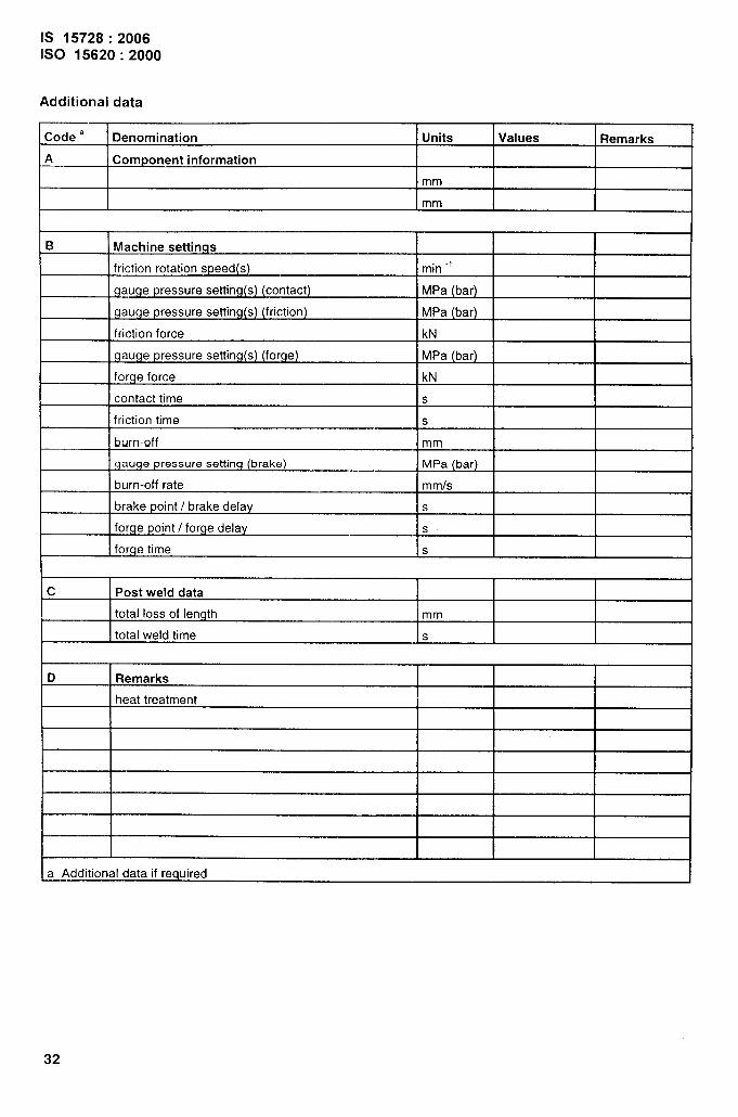
Additional data
Code a Denomination Units Values Remarks
A Component information
mm
I mm I II
B Machine settings
friction rotation speed(s) min “1
gauge pressure setting(s) (contact) MPa (bar)
gauge pressure setting(s) (friction) MPa (bar)
friction force kN
gauge pressure setting(s) (forge) MPa (bar)
forge force kN
contact time s
friction time s
burn-off mm
qauge pressure setting (brake) MPa (bar)Iburn-off rate mmls
brake point / brake delay s
forge point / forge delay s
forge time s
c Post weld data
total loss of length mm
total weId time s
D Remarks
heat treatment
a Additional data if required I

IS 15728:2006ISO 15620:2000
Test results
SpecimenNo. Bendingangle0 Locationof Remarks Assessmentfracture
,
Further remarks:
33

Bureau of Indian Standards
BIS is a statutory institution established under the Bureau of Indian Standards Act, 1986 to promoteharmonious development of the activities of standardization, marking and quality certification of goodsand attending to connected matters in the country.
Copyright
BIS has the copyright of all its publications. No part of these publications maybe reproduced in any formwithout the prior permission in writing of BIS. This does not preclude the free use, in the course ofimplementing the standard, of necessary details, such as symbols and sizes, type or grade designations.Enquiries relating to copyright be addressed to the Director (Publications), BIS.
Review of Indian Standards
Amendments are issued to standards as the need arises on the basis of comments. Standards are alsoreviewed periodically; a standard along with amendments is reaffirmed when such review indicates thatno changes are needed; if the review indicates that changes are needed, it is taken up for revision.Users of Indian Standards should ascertain that they are in possession of the latest amendments oredition by referring to the latest issue of ‘BIS Catalogue’ and ‘Standards: Monthly Additions’.
This Indian Standard has been developedfrom Doc: No. MTD 12 (4638).
Amendments Issued Since Publication
Amend No. Date of Issue Text Affected
BUREAU OF INDIAN STANDARDS
Headquarters:
Manak Bhavan, 9 Bahadur Shah Zafar Marg, New Delhi 110002 Telegrams: ManaksansthaTelephones: 23230131,23233375,23239402 (Common to all offices)
Regional Offices : Telephone
Central :
Eastern :
Northern :
Southern :
Western :
Branches
Manak Bhavan, 9 Bahadur Shah Zafar Marg
{
23237617NEW DELHI 110002 23233841
1/14 C.I.T. Scheme Vll M, V. 1.P. Road, Kankurgachi
{
23378499,23378561
KOLKATA 700054 23378626,23379120
SCO 335-336, Sector 34-A, CHANDIGARH 160022
{
26038432609285
C.I.T. Campus, IV Cross Road, CHENNAI 600113
{
22541216,2254144222542519,22542315
Manakalaya, E9 MlDC, Marol, Andheri (East)
{
28329295,28327858MUMBAI 400093 28327891,28327892
: AHMEDABAD. BANGALORE. BHOPAL. BHUBANESHWAR. COIMBATORE< FARIDABAD.GHAZIABAD. GUWAHATI. HYDERABAD. JAIPUR. KANPUR. LUCKNOW. NAGPUR.NALAGARH. PATNA. PUNE. RAJKOT. THIRUVANANTHAPURAM. VISAKHAPATNAM.
Printed at Prabhat Offset Press, New Delhi-2